JP7587828B2 - Control valve - Google Patents
Control valve Download PDFInfo
- Publication number
- JP7587828B2 JP7587828B2 JP2021047608A JP2021047608A JP7587828B2 JP 7587828 B2 JP7587828 B2 JP 7587828B2 JP 2021047608 A JP2021047608 A JP 2021047608A JP 2021047608 A JP2021047608 A JP 2021047608A JP 7587828 B2 JP7587828 B2 JP 7587828B2
- Authority
- JP
- Japan
- Prior art keywords
- valve
- valve body
- hole
- seal ring
- tapered surface
- Prior art date
- Legal status (The legal status is an assumption and is not a legal conclusion. Google has not performed a legal analysis and makes no representation as to the accuracy of the status listed.)
- Active
Links
Images


Classifications
-
- F—MECHANICAL ENGINEERING; LIGHTING; HEATING; WEAPONS; BLASTING
- F25—REFRIGERATION OR COOLING; COMBINED HEATING AND REFRIGERATION SYSTEMS; HEAT PUMP SYSTEMS; MANUFACTURE OR STORAGE OF ICE; LIQUEFACTION SOLIDIFICATION OF GASES
- F25B—REFRIGERATION MACHINES, PLANTS OR SYSTEMS; COMBINED HEATING AND REFRIGERATION SYSTEMS; HEAT PUMP SYSTEMS
- F25B41/00—Fluid-circulation arrangements
- F25B41/30—Expansion means; Dispositions thereof
- F25B41/31—Expansion valves
- F25B41/325—Expansion valves having two or more valve members
-
- F—MECHANICAL ENGINEERING; LIGHTING; HEATING; WEAPONS; BLASTING
- F16—ENGINEERING ELEMENTS AND UNITS; GENERAL MEASURES FOR PRODUCING AND MAINTAINING EFFECTIVE FUNCTIONING OF MACHINES OR INSTALLATIONS; THERMAL INSULATION IN GENERAL
- F16K—VALVES; TAPS; COCKS; ACTUATING-FLOATS; DEVICES FOR VENTING OR AERATING
- F16K1/00—Lift valves or globe valves, i.e. cut-off apparatus with closure members having at least a component of their opening and closing motion perpendicular to the closing faces
- F16K1/32—Details
- F16K1/34—Cutting-off parts, e.g. valve members, seats
- F16K1/42—Valve seats
-
- F—MECHANICAL ENGINEERING; LIGHTING; HEATING; WEAPONS; BLASTING
- F16—ENGINEERING ELEMENTS AND UNITS; GENERAL MEASURES FOR PRODUCING AND MAINTAINING EFFECTIVE FUNCTIONING OF MACHINES OR INSTALLATIONS; THERMAL INSULATION IN GENERAL
- F16K—VALVES; TAPS; COCKS; ACTUATING-FLOATS; DEVICES FOR VENTING OR AERATING
- F16K25/00—Details relating to contact between valve members and seats
- F16K25/005—Particular materials for seats or closure elements
-
- F—MECHANICAL ENGINEERING; LIGHTING; HEATING; WEAPONS; BLASTING
- F16—ENGINEERING ELEMENTS AND UNITS; GENERAL MEASURES FOR PRODUCING AND MAINTAINING EFFECTIVE FUNCTIONING OF MACHINES OR INSTALLATIONS; THERMAL INSULATION IN GENERAL
- F16K—VALVES; TAPS; COCKS; ACTUATING-FLOATS; DEVICES FOR VENTING OR AERATING
- F16K31/00—Actuating devices; Operating means; Releasing devices
- F16K31/02—Actuating devices; Operating means; Releasing devices electric; magnetic
- F16K31/04—Actuating devices; Operating means; Releasing devices electric; magnetic using a motor
-
- F—MECHANICAL ENGINEERING; LIGHTING; HEATING; WEAPONS; BLASTING
- F16—ENGINEERING ELEMENTS AND UNITS; GENERAL MEASURES FOR PRODUCING AND MAINTAINING EFFECTIVE FUNCTIONING OF MACHINES OR INSTALLATIONS; THERMAL INSULATION IN GENERAL
- F16K—VALVES; TAPS; COCKS; ACTUATING-FLOATS; DEVICES FOR VENTING OR AERATING
- F16K31/00—Actuating devices; Operating means; Releasing devices
- F16K31/12—Actuating devices; Operating means; Releasing devices actuated by fluid
- F16K31/36—Actuating devices; Operating means; Releasing devices actuated by fluid in which fluid from the circuit is constantly supplied to the fluid motor
- F16K31/40—Actuating devices; Operating means; Releasing devices actuated by fluid in which fluid from the circuit is constantly supplied to the fluid motor with electrically-actuated member in the discharge of the motor
- F16K31/406—Actuating devices; Operating means; Releasing devices actuated by fluid in which fluid from the circuit is constantly supplied to the fluid motor with electrically-actuated member in the discharge of the motor acting on a piston
- F16K31/408—Actuating devices; Operating means; Releasing devices actuated by fluid in which fluid from the circuit is constantly supplied to the fluid motor with electrically-actuated member in the discharge of the motor acting on a piston the discharge being effected through the piston and being blockable by an electrically-actuated member making contact with the piston
-
- F—MECHANICAL ENGINEERING; LIGHTING; HEATING; WEAPONS; BLASTING
- F16—ENGINEERING ELEMENTS AND UNITS; GENERAL MEASURES FOR PRODUCING AND MAINTAINING EFFECTIVE FUNCTIONING OF MACHINES OR INSTALLATIONS; THERMAL INSULATION IN GENERAL
- F16K—VALVES; TAPS; COCKS; ACTUATING-FLOATS; DEVICES FOR VENTING OR AERATING
- F16K31/00—Actuating devices; Operating means; Releasing devices
- F16K31/44—Mechanical actuating means
- F16K31/50—Mechanical actuating means with screw-spindle or internally threaded actuating means
-
- F—MECHANICAL ENGINEERING; LIGHTING; HEATING; WEAPONS; BLASTING
- F25—REFRIGERATION OR COOLING; COMBINED HEATING AND REFRIGERATION SYSTEMS; HEAT PUMP SYSTEMS; MANUFACTURE OR STORAGE OF ICE; LIQUEFACTION SOLIDIFICATION OF GASES
- F25B—REFRIGERATION MACHINES, PLANTS OR SYSTEMS; COMBINED HEATING AND REFRIGERATION SYSTEMS; HEAT PUMP SYSTEMS
- F25B41/00—Fluid-circulation arrangements
- F25B41/30—Expansion means; Dispositions thereof
- F25B41/31—Expansion valves
- F25B41/34—Expansion valves with the valve member being actuated by electric means, e.g. by piezoelectric actuators
- F25B41/35—Expansion valves with the valve member being actuated by electric means, e.g. by piezoelectric actuators by rotary motors, e.g. by stepping motors
-
- F—MECHANICAL ENGINEERING; LIGHTING; HEATING; WEAPONS; BLASTING
- F25—REFRIGERATION OR COOLING; COMBINED HEATING AND REFRIGERATION SYSTEMS; HEAT PUMP SYSTEMS; MANUFACTURE OR STORAGE OF ICE; LIQUEFACTION SOLIDIFICATION OF GASES
- F25B—REFRIGERATION MACHINES, PLANTS OR SYSTEMS; COMBINED HEATING AND REFRIGERATION SYSTEMS; HEAT PUMP SYSTEMS
- F25B2500/00—Problems to be solved
- F25B2500/12—Sound
Landscapes
- Engineering & Computer Science (AREA)
- General Engineering & Computer Science (AREA)
- Mechanical Engineering (AREA)
- Physics & Mathematics (AREA)
- Thermal Sciences (AREA)
- Electrically Driven Valve-Operating Means (AREA)
- Lift Valve (AREA)
Description
本発明は制御弁に関し、特に弁部の開閉構造に関する。 The present invention relates to a control valve, and in particular to the opening and closing structure of the valve section.
自動車用空調装置は、一般に、圧縮機、凝縮器、膨張装置、蒸発器等を冷凍サイクルに配置して構成される。冷凍サイクルには、膨張装置としての膨張弁など、冷媒の流れを制御するために各種制御弁が設けられている。近年の電気自動車等の普及に伴い、駆動部としてモータを備える電動弁が広く採用されつつある。 Automotive air conditioners are generally configured with a compressor, condenser, expansion device, evaporator, etc., arranged in a refrigeration cycle. The refrigeration cycle is provided with various control valves to control the flow of refrigerant, such as an expansion valve as an expansion device. With the recent spread of electric vehicles, motor-operated valves equipped with a motor as a drive unit are becoming more widely used.
電動弁は、ロータと同軸状に設けられたシャフトと、シャフトと一体変位可能な弁体と、ロータの回転運動をシャフトの並進運動に変換するねじ送り機構を備える。ロータの回転により、弁体を弁部の開閉方向に作動させることができる。このような電動弁として、閉弁状態において弁体に適度な閉弁荷重を付与する構造を採用するものがある(例えば特許文献1参照)。それにより、良好な閉弁性能を確保することができる。 The motor-operated valve comprises a shaft that is coaxial with the rotor, a valve body that can be displaced integrally with the shaft, and a screw feed mechanism that converts the rotational motion of the rotor into the translational motion of the shaft. The valve body can be operated in the opening and closing directions of the valve section by the rotation of the rotor. Some such motor-operated valves employ a structure that applies an appropriate closing load to the valve body when the valve is closed (see, for example, Patent Document 1). This ensures good valve closing performance.
しかしながら、特許文献1の電動弁では後述のように、開弁開始時に弁体の受圧径が変化することでその閉弁荷重が増加し、これが開弁時の抵抗となり、モータの回転トルクを増大させる可能性がある。すなわち、開弁時にモータ負荷が大きくなる点で改善の余地があった。このような問題は、冷凍サイクルに用いられる電動弁に限らず、開弁時に閉弁荷重が増大する制御弁であれば同様に生じ得る。 However, as described below, in the motor-operated valve of Patent Document 1, when the valve starts to open, the pressure-receiving diameter of the valve body changes, increasing the closing load, which creates resistance when the valve opens and can increase the rotational torque of the motor. In other words, there is room for improvement in the fact that the motor load increases when the valve opens. This problem is not limited to motor-operated valves used in refrigeration cycles, but can occur in any control valve in which the closing load increases when the valve opens.
本発明の目的の一つは、制御弁の開弁時においてアクチュエータへの負荷を低減させる構造を提供することにある。 One of the objectives of the present invention is to provide a structure that reduces the load on the actuator when the control valve is opened.
本発明のある態様の制御弁は、流体を導入する導入ポートと、流体を導出する導出ポートと、導入ポートと導出ポートとを連通させる弁孔と、弁孔に設けられた弁座とを有するボディと、弁座に下流側から着脱して弁部を開閉する弁体と、弁体を弁部の開閉方向に駆動するアクチュエータと、を備える。弁部の開閉構造は、弁体の先端部が弁孔に同軸状に挿抜される挿抜構造と、弁体の先端部が弁孔に挿入された状態で、弁体および弁座の一方のエッジ部と他方のテーパ面とが着脱する着脱構造と、を含む。 A control valve according to one embodiment of the present invention comprises a body having an inlet port for introducing a fluid, an outlet port for discharging the fluid, a valve hole that connects the inlet port and the outlet port, a valve seat provided in the valve hole, a valve element that is attached to and detached from the valve seat from the downstream side to open and close the valve section, and an actuator that drives the valve element in the opening and closing direction of the valve section. The opening and closing structure of the valve section includes an insertion/removal structure in which the tip of the valve element is inserted and removed coaxially into the valve hole, and an attachment/detachment structure in which one edge portion of the valve element and one tapered surface of the valve seat are attached and detached with the tip of the valve element inserted into the valve hole.
この態様によると、弁体の先端部が弁孔に挿入された状態で、弁体および弁座の一方のエッジ部と他方のテーパ面とが着脱する構成としたことで、弁部の閉弁および寸開状態において弁体の先端部と弁孔との間にクリアランスが形成される。それにより、開弁時における弁体の受圧径の変化を抑制でき、弁体に作用する閉弁方向の荷重の増大を抑制できる。その結果、アクチュエータの負荷を抑えることができる。 According to this embodiment, when the tip of the valve body is inserted into the valve hole, one edge of the valve body and the valve seat can be detached from the other tapered surface, so that a clearance is formed between the tip of the valve body and the valve hole when the valve part is in the closed and slightly open states. This makes it possible to suppress changes in the pressure-receiving diameter of the valve body when the valve is open, and suppresses increases in the load acting on the valve body in the closing direction. As a result, the load on the actuator can be suppressed.
本発明によれば、制御弁の開弁時においてアクチュエータへの負荷を低減させる構造を提供できる。 The present invention provides a structure that reduces the load on the actuator when the control valve is open.
以下、本発明の実施形態を、図面を参照して詳細に説明する。なお、以下の説明においては便宜上、図示の状態を基準に各構造の位置関係を表現することがある。また、以下の実施形態およびその変形例について、ほぼ同一の構成要素については同一の符号を付し、その説明を適宜省略する。 Embodiments of the present invention will be described in detail below with reference to the drawings. In the following description, for convenience, the positional relationship of each structure may be expressed based on the illustrated state. In addition, in the following embodiments and their modified examples, substantially identical components are given the same reference numerals, and their description will be omitted as appropriate.
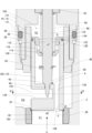
図1は、実施形態に係る電動弁を表す断面図である。
電動弁1は、図示しない車両用冷暖房装置の冷凍サイクルに適用される。電動弁1は、大口径の第1弁2と小口径の第2弁4を同軸状に備え、これらの弁を共用のアクチュエータで駆動する複合弁である。第1弁2および第2弁4はそれぞれ弁開度を調整可能な比例弁である。第1弁2は、冷媒循環通路を開閉する開閉弁としても機能し得る。第2弁4は、上流側からの冷媒を絞り膨張させる膨張弁としても機能し得る。
FIG. 1 is a cross-sectional view illustrating a motor-operated valve according to an embodiment.
The motor-operated valve 1 is applied to a refrigeration cycle of a vehicle air conditioner (not shown). The motor-operated valve 1 is a composite valve that includes a large-diameter
電動弁1は、弁本体6とモータユニット8とを組み付けて構成される。弁本体6とモータユニット8とは、接続部材9を介して固定される。弁本体6は、第1弁2および第2弁4を収容する共用のボディ10を有する。ボディ10は、第1ボディ12、第2ボディ14およびガイド部材16を同軸状に組み付けて構成される。本実施形態では、いずれのボディもステンレス鋼(以下「SUS」と表記する)からなる。
The motor-operated valve 1 is constructed by assembling a
第1ボディ12は、有底筒状(ブロック状)をなし、その一側面下部に導入ポート18が開口し、その反対側面上部に導出ポート20が開口する。第1ボディ12には、導入ポート18と導出ポート20とを連通させる冷媒通路22が形成されている。上流側からの冷媒は、導入ポート18を介して冷媒通路22に導入され、弁部を経由した後に導出ポート20を介して下流側へ導出される。第1ボディ12の上半部中央に段付円孔状の取付孔26が設けられ、冷媒通路22の中間部と連通している。取付孔26は上方に向けて段階的に拡径し、ガイド部材16、第2ボディ14が順次挿通され、組み付けられている。
The
冷媒通路22の中間部に設けられた段部に、環状の弁座形成部材28が圧入されている。弁座形成部材28の内方には、取付孔26と同軸状の第1弁孔30が形成されている。第1弁孔30の下流側開口部に第1弁座32が形成されている。弁座形成部材28の内周面には、第1弁孔30および第1弁座32に沿ってゴムの焼き付けがなされ、シール性の向上が図られている(詳細後述)。
An annular valve
第2ボディ14は、段付円筒状をなし、その下半部が取付孔26に挿入され、第1ボディ12に組み付けられている。取付孔26の内周面に雌ねじ33が形成され、第2ボディ14の下部外周面に雄ねじ35が形成されている。第2ボディ14は、それらのねじにより第1ボディ12に締結されている。第2ボディ14の外周面(雄ねじ35のやや上方)には環状溝からなるシール収容部34が形成され、シールリング36(Oリング)が嵌着されている。シールリング36が取付孔26と第2ボディ14との間に介装されることにより、弁本体6の内部から外部への冷媒を漏洩が防止されている。
The
ガイド部材16は、SUSからなる円筒状部材に潤滑めっきを施して得られる。ガイド部材16の下部がやや拡径され、取付孔26の下部に圧入されている。それにより、ガイド部材16が第1ボディ12に対して固定されている。ガイド部材16の内周面によりガイド孔38が形成されている。取付孔26の内周面とガイド部材16の外周面との間に形成される環状の空間に第2ボディ14の下半部が挿入されている。第2ボディ14とガイド部材16との間には所定のクリアランスが設けられ、両者は当接しない。
The
ガイド部材16の内方に第1弁体40が配設されている。第1弁体40は、有底円筒状をなし、ガイド孔38に摺動可能に支持される。第1弁体40が第1弁座32に下流側から着脱することにより第1弁2を開閉する。一方、第1弁体40には内部通路42が形成され、その内部通路42の中間に第2弁孔44が形成されている。第2弁孔44の上流側開口部に第2弁座46が形成されている。
A
ボディ10の内方には、モータユニット8のロータ60から延びる作動ロッド48が挿通されている。作動ロッド48の下部は、第1弁体40に同軸状に挿通される。作動ロッド48は、非磁性金属からなる棒材を切削加工して得られ、その下部にニードル状の第2弁体50が一体に設けられている。第2弁体50が上流側から第2弁座46に着脱することにより第2弁4を開閉する。
An operating
第2ボディ14の上部中央には、ガイド部材52が立設されている。ガイド部材52は、非磁性金属からなる管材を段付円筒状に切削加工して得られ、その軸線方向中央部の外周面に雄ねじ54が形成されている。ガイド部材52の下端部が大径となっており、その大径部56が第2ボディ14の上部中央に圧入され、同軸状に固定されている。ガイド部材52は、その内周面により作動ロッド48を軸線方向に摺動可能に支持する一方、その外周面によりロータ60の回転軸62を回転摺動可能に支持する。
A
ガイド部材52と第1弁体40との間には、第1弁体40を閉弁方向に付勢するスプリング58(「付勢部材」として機能する)が介装されている。作動ロッド48における第2弁体50のやや上方に、半径方向に突出した係止部59が設けられている。係止部59は、例えばEリングからなる。この係止部59を第1弁体40に引っ掛けることにより、スプリング58の付勢力に抗して第1弁体40を開弁方向に引き上げることができる。この第1弁体40と第2弁体50とを作動ロッド48を介して一体変位可能に作動連結する機構を「作動連結機構」という。その詳細については後述する。
Between the
一方、モータユニット8は、ロータ60とステータ64とを含むステッピングモータとして構成されている。モータユニット8は、有底円筒状のキャン66を有し、そのキャン66の内方にロータ60を配置し、外方にステータ64を配置して構成されている。キャン66は、第2弁体50およびその駆動機構が配置される空間を覆うとともにロータ60を内包する有底円筒状の部材であり、冷媒の圧力が作用する内方の圧力空間(内部空間)と作用しない外方の非圧力空間(外部空間)とを画定する。
On the other hand, the
キャン66は、非磁性金属(本実施形態ではSUS)からなり、その下部が第2ボディ14の上端部に外挿されるようにして同軸状に組み付けられている。キャン66の下端部と第2ボディ14との境界に沿って全周溶接が施されることにより(図示略)、ボディ10とキャン66との固定およびシールが実現されている。ボディ10とキャン66とに囲まれた空間が、上記圧力空間を形成している。
The
ガイド部材16を第2ボディ14とは別部材としたことで、溶接部品(第2ボディ14)と潤滑コーティング部品(ガイド部材16)とを分けて作製できる。このため、ガイド孔38にめっき膜を塗装したり蒸着させる等の手間をかけることなく、ガイド部材16の素材全体をめっき液に浸漬させるだけで足り、製造工程が簡素化される。
By making the guide member 16 a separate member from the
ステータ64は、コイル68が巻回されたボビン70を、複数の極歯を有するヨーク72に組み付けて構成される。ステータ64は、モータユニット8のケース76と一体に設けられている。すなわち、ケース76は、耐食性を有する樹脂材の射出成形(「インサート成形」又は「モールド成形」ともいう)により得られる。ステータ64は、その射出成形によるモールド樹脂によって被覆されている。ケース76は、そのモールド樹脂からなる。以下、ステータ64とケース76とのモールド成形品を「ステータユニット78」とも称する。
The
ステータユニット78は、中空構造を有し、キャン66を同軸状に挿通しつつボディ10に組み付けられている。第2ボディ14の上部外周面には、環状溝からなるシール収容部80が形成され、シールリング82(Oリング)が嵌着されている。第2ボディ14とケース76とに間にシールリング82が介装されることにより、キャン66とステータ64との間隙への外部雰囲気(水など)の侵入が防止されている。
The
ロータ60は、回転軸62に組み付けられた円筒状のロータコア84と、ロータコア84の外周面に設けられたロータマグネット86を備える。ロータコア84は、回転軸62に組み付けられている。ロータマグネット86は、その周方向に複数極に磁化(着磁)されている。
The
回転軸62は、有底円筒状の円筒軸であり、その開口端を下にしてガイド部材52に外挿されている。回転軸62の下部内周面に雌ねじ88が形成され、ガイド部材52の雄ねじ54と噛合している。これらのねじ部によるねじ送り機構90によって、ロータ60の回転運動が作動ロッド48の軸線運動に変換される。それにより第2弁体50が軸線方向、つまり弁部の開閉方向に移動(昇降)する。
The rotating
作動ロッド48の上部が縮径され、その縮径部92が回転軸62の底部94を貫通している。縮径部92の先端部には環状のストッパ96が固定されている。一方、縮径部92の基端と底部94との間には、作動ロッド48を下方(つまり閉弁方向)に付勢するスプリング98が介装されている。このような構成により、開弁時には、ストッパ96が底部94に係止される態様で作動ロッド48がロータ60と一体変位する。一方、閉弁時には、第2弁体50が第2弁座46から受ける反力によりスプリング98が押し縮められる。このときのスプリング98の弾性反力により第2弁体50を第2弁座46に押し付けることができ、第2弁体50の着座性能(弁閉性能)を高められる。
The upper part of the
モータユニット8は、キャン66の外側に回路基板100を有する。回路基板100は、ケース76の内方に固定されている。本実施形態では、回路基板100の下面に制御部や通信部として機能する各種回路が実装されている。具体的には、モータを駆動するための駆動回路、駆動回路に制御信号を出力する制御回路(マイクロコンピュータ)、制御回路が外部装置と通信するための通信回路、各回路およびモータ(コイル)に電力を供給するための電源回路等が実装されている。ケース76の上端は、蓋体77により閉止されている。ケース76における蓋体77の下方の空間に回路基板100が配設されている。
The
ボビン70からはコイル68につながる端子102が延出し、回路基板100に接続されている。回路基板100からは電源端子、グランド端子および通信端子(これらを総称して「接続端子104」ともいう)が延出し、それぞれケース76の側壁を貫通して外部に引き出されている。ケース76の側部にコネクタ部106が一体に設けられ、そのコネクタ部106の内方に接続端子104が配置されている。
A terminal 102 connected to the
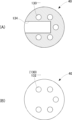
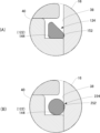
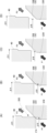
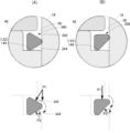
図2は、図1のA部拡大図である。図3は、第1弁体40の内部通路の構成を表す図である。図3(A)は図2のB-B矢視断面に対応し、図3(B)は図2のC方向矢視に対応する。図4は、第1弁体40周辺の要部拡大図である。図4(A)は図2のD部拡大図であり、図4(B)は図2のE部拡大図である。
Figure 2 is an enlarged view of part A in Figure 1. Figure 3 is a diagram showing the configuration of the internal passage of the
図2に示すように、第1弁体40は、底部が十分な厚みを有する有底円筒状をなしている。第1弁体40の上方には背圧室108が形成されている。背圧室108は、ガイド部材52、第2ボディ14、ガイド部材16および第1弁体40に囲まれる空間である。第1弁体40の内方(底部の上方)に弁室110が形成されている。第1弁体40の上部には、有底段付円筒状の作動連結部材112が同軸状に挿通され固定されている。作動連結部材112は、真鍮などの第1弁体40よりも軟らかく加工性に優れた材質からなる。
As shown in FIG. 2, the
作動連結部材112は、その底部中央に挿通孔114を有する。作動ロッド48がその挿通孔114を同軸状に貫通している。作動連結部材112の側部には、内外を連通させる複数の連通孔116が設けられている。連通孔116は、弁室110と背圧室108とを連通させる。作動連結部材112は、その上部が第1弁体40の上端開口部に圧入されることで第1弁体40に固定されている。
The
作動連結部材112の上端には、半径方向外向きに延出するフランジ部118が設けられている。一方、第1弁体40の上端外周縁に沿って環状の段差120が設けられている。第1弁体40の上部には、これらフランジ部118と段差120とによる環状のシール収容部122が形成されている。そのシール収容部122に、シールリング124が嵌着されている。そのシールリング124により、第1弁体40とガイド部材16との間隙を介した冷媒の流通が規制されている。シールリング124およびその周辺の詳細については後述する。
The upper end of the
作動連結部材112の底部は、スプリング58を支持するばね受けとしても機能する。すなわち、スプリング58は、作動ロッド48に同軸状に外挿され、ガイド部材52の底部と作動連結部材112の底部との間に介装されている。スプリング58の付勢力は、作動連結部材112を介して第1弁体40に伝達される。また、第2弁体50の開弁作動により係止部59が第1弁体40に対して相対変位し、作動連結部材112の底面に当接してこれを押し上げることにより、第1弁体40を開弁方向に作動させることができる。
The bottom of the
ガイド孔38における第1弁体40の外周面との対向面には、部分的に微小に拡径された拡径部126が設けられている。拡径部126は、ガイド孔38の軸線方向中央部から下部にかけて設けられ、第1弁体40との間にクリアランスを形成する。ただし図示のように、第1弁体40は、その上部と下部においてガイド孔38に当接し、安定した摺動が可能となっている。このように拡径部126を設けることで、第1弁体40とガイド孔38との摺動面積を制限することで、第1弁体40の摺動抵抗を低減している。
The surface of the
また上述のように、ガイド孔38には潤滑めっきが施されている。潤滑めっきの材質としては、ポリテトラフルオロエチレン(以下、「PTFE」と表記することがある。)を含んだニッケル-リン(Ni-P)等既知の潤滑めっき材を用いることができる。このような摺動面の表面処理によっても摺動抵抗の低減が図られている。
As mentioned above, the
第1弁体40の底部を軸線と平行に貫通する複数(本実施形態では5つ)の連通孔130(小孔)が設けられている(図3(A),(B))。これらの連通孔130の下端開口部が入口ポート132となっている。連通孔130は、第1弁孔30における第1弁座32よりも上流側と弁室110とを連通させる。連通孔130、弁室110および連通孔116が、第1弁座32の上流側と背圧室108とを連通させる「連通路」を構成する。また、第1弁体40の底部には、軸線と直角方向に延びる下流側通路134が設けられている。下流側通路134は、導出ポート20側に向けて開口する出口ポート136を有する。
The
第2弁孔44は、弁室110と下流側通路134とを連通させる。連通孔130は、下流側通路134とは交差しないように配設されている。下流側通路134の流路断面は、連通孔130の流路断面よりも十分に大きい。複数の連通孔130、弁室110、第2弁孔44および下流側通路134が、第1弁体40の内部通路42を構成する。第2弁体50は、その先端部が第2弁孔44を貫通し、テーパ面にて第2弁座46に着脱する。
The
図示のような第1弁2の閉弁時や寸開時には、第1弁座32の上流側の圧力(上流側圧力P1)が、第1弁座32の下流側の圧力(下流側圧力P2)よりも高くなる。一方、背圧室108は、弁室110および連通孔130を介して第1弁座32の上流側と連通するため、背圧室108の圧力(「背圧」ともいう)は、上流側圧力P1とほぼ等しくなる。このため、第1弁体40に作用する流体圧力がほとんどキャンセルされる。
When the
本実施形態では、第1弁2の閉弁性能を高めるために、第1弁体40の摺動部径d1(ガイド孔38の内径)をシール部径d2(弁座の外径)よりもやや大きくしている。しかし、その径の差が微小であるため、上述のように、第1弁体40に作用する流体圧力はほとんどキャンセルされる。このため、第1弁体40を開弁方向に引き上げるときの抵抗を小さくでき、第1弁2の開弁に要するモータユニット8の回転トルク(回転駆動力)を抑えることができる。
In this embodiment, in order to improve the closing performance of the
一方、第1弁体40とガイド孔38との間隙には、上流側圧力P1と下流側圧力P2との差圧(P1-P2)が発生する。この点、本実施形態ではシールリング124が配設されたことで、その間隙を介した高圧側から低圧側への冷媒の漏れが規制される。
Meanwhile, a pressure difference (P1-P2) between the upstream pressure P1 and the downstream pressure P2 occurs in the gap between the
図4(A)に示すように、シール収容部122は、底面140と高圧側面142と低圧側面144を有し、第1弁体40の上部外周面に沿って設けられた環状の凹部である。一方、シールリング124は、三角形状の断面を有する三角リングであり、その一つの頂点においてガイド孔38の内周面と当接する。
As shown in FIG. 4A, the
より詳細には、シールリング124の断面形状は、頂点がR面取りされた直角三角形状をなしている。シールリング124の内周面146が平坦面とされ、その内周面146と直角をなす下面148が、シール収容部122の低圧側面144に当接する。シールリング124の上面150が傾斜面(テーパ面)とされ、上面150と下面148とがつながる頂部によりシールリング124の外周面152が構成される。シールリング124は、その外周面152においてガイド孔38に摺動することとなる。
More specifically, the cross-sectional shape of the
このような構成のため、シールリング124は、ガイド孔38の内周面との接触面積が、シール収容部122の低圧側面144との接触面積よりも小さくなる。言い換えれば、Oリング等の場合と比較してシールリング124とガイド孔38との摺動面積を小さくでき、第1弁体40の摺動抵抗を低減できる。
Due to this configuration, the contact area of the
シール収容部122の幅(つまり高圧側面142と低圧側面144との間隔)は、シールリング124の軸線方向の幅(つまり第1弁体40の軸線方向の幅)よりも大きい。第1弁2の閉弁又は寸開状態においては、シールリング124に差圧(P1-P2)が作用するため、図示のように、シールリング124が低圧側面144に密着する。シール収容部122の底面140とシールリング124の内周面146との間(底面140とシールリング124との対向面の間)に空隙Sが形成される。このため、差圧によりシールリング124が軸線方向に圧縮されて変形したとしても、その内周面146が底面140に当接することはない。このため、底面140からの反力によってシールリング124がガイド孔38に押し付けられることもなく、摺動抵抗の上昇を回避できる。
The width of the seal housing 122 (i.e., the distance between the
図4(B)に示すように、弁座形成部材28には、SUSからなる本体160の内周面に沿ってゴム162の焼き付けがなされている。弁座形成部材28の上端開口部には、第1弁座32(着脱面)として機能する第1テーパ面164と、第1弁孔30の開口端を形成する第2テーパ面166が設けられている。第1弁孔30は、第1テーパ面164と第2テーパ面166との間に第1弁体40の軸線に平行なストレート部168を含む二段テーパ構造を有する。本体160において第1弁座32に対応する部分は直角な段差部170が設けられ、第1テーパ面164との間にゴム162の厚肉部が設けられている。すなわち、第1弁座32の位置においてゴム162の厚みが大きくされている。それにより、第1弁座32の耐久性を高めている。
As shown in FIG. 4B, the valve
第1弁体40は、その下端部(先端部)においてやや小径化された小径部172を有する。小径部172の下端外周縁がエッジ部174とされている。エッジ部174は、ほぼ直角な断面を有するが、第1弁座32を傷つけない程度に微小なR面取りがなされている。第1弁2は、その開閉構造として、小径部172が第1弁孔30に同軸状に挿抜される挿抜構造と、小径部172が第1弁孔30に挿入された状態でエッジ部174が第1テーパ面164に着脱する着脱構造を有する。
The
次に、電動弁1の動作について説明する。
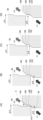
図5は、電動弁1の動作過程を表す図である。図5(A)は、第1弁2および第2弁4の閉弁状態を示す。図5(B)は、第1弁2の閉弁状態かつ第2弁4の開弁状態を示す。図5(C)は、第1弁2および第2弁4の開弁状態を示す。
Next, the operation of the motor-operated valve 1 will be described.
Figure 5 is a diagram showing the operation process of the motor-operated valve 1. Figure 5(A) shows the
モータユニットを開弁方向に駆動して作動ロッド48を上方へ作動させると、第2弁体50が第2弁座46から離脱する(図5(A),(B))。それにより、連通孔130、弁室110、第2弁孔44および下流側通路134が連通する。上流側からの冷媒は、第1弁体40の内部通路42を流れ、第2弁4を経由して下流側へ導出される。このとき、第2弁4を所定開度に調整することで膨張弁として機能させることができる。
When the motor unit is driven in the valve opening direction to operate the
さらに作動ロッド48を開弁方向へ作動させると、係止部59が作動連結部材112に係合し、作動ロッド48と第1弁体40とが作動連結する(図5(C))。そして、作動ロッド48がスプリング58の付勢力に抗して第1弁体40を引き上げる。それにより、第1弁体40が第1弁座32から離脱し、第1弁2が開弁する。冷媒は、第1弁2および第2弁4の双方を経由して下流側へ流れる。このとき、大流量の冷媒を流すこともできるが、その流量は第1弁2の開度により調整できる。
When the operating
モータユニットを閉弁方向に駆動すると、上記とは逆に、作動ロッド48が下方へ作動する。このとき、第1弁体40は、スプリング58の付勢力により作動ロッド48との作動連結が維持されたまま閉弁方向へ作動する。そしてまず、第1弁体40が第1弁座32に着座し、第1弁2が閉弁状態となる。さらに作動ロッド48を閉弁方向へ作動させると、係止部59が作動連結部材112から離脱し、作動ロッド48と第1弁体40との作動連結は解除される。その後、第2弁体50が第2弁座46に着座し、第2弁4が閉弁状態となる。なお、第1弁体40への閉弁方向の荷重は、第2弁4の開弁状態など電動弁1の特定の作動状態においてはモータユニットからは付与されず、スプリング58により付与される。
When the motor unit is driven in the valve closing direction, the operating
次に、本実施形態の作用効果について説明する。
図6は、シールリング124による摺動抵抗低減構造を表す部分拡大図である。図6(A)は本実施形態の構造を示し、図6(B)は比較例1の構造を示す。比較例1は、シールリングとしてOリングを採用する場合を示す。
Next, the effects of this embodiment will be described.
6A and 6B are partial enlarged views showing a sliding resistance reduction structure using a
本実施形態のシールリング124は、既に説明したように直角三角形状の断面を有し、その一つの頂部(外周面152)をガイド孔38に密着させることでシール性を確保する(図6(A))。シールリング124は、シール収容部122の低圧側面144と相補形状の平坦面で当接し、かつその接触面積が十分に大きい。このため、差圧(P1-P2)を受けても、シールリング124は変形し難く、その形状を安定に保持する。その結果、第1弁体40は、摺動抵抗を小さく抑えつつ、ガイド孔38に沿って安定に摺動できる。
As already explained, the
これに対し、比較例1のOリング224は、摺動部に装着するシールリングとして一般的ではあるが、ガイド孔38の内周面との接触面積が、シール収容部122の低圧側面144との接触面積よりも大きい。Oリング224は、差圧(P1-P2)を受けると、軸線方向につぶされ、径方向に膨張する。このため、本実施形態と比較して、第1弁体40の摺動抵抗が大きくなる。言い換えれば、本実施形態のシールリング124を採用することにより、摺動抵抗を効果的に低減できる。
In contrast, the O-
図7および図8は、第1弁2の構造による差圧低減作用を表す図である。図7(A)~(D)は、本実施形態の弁構造を採用した場合の開弁時の受圧面積の変化を示す。図8(A)~(D)は、比較例2の弁構造を採用した場合の開弁時の受圧面積の変化を示す。比較例2の弁構造は、本実施形態の挿抜構造(図4(B)参照)を有していない。
Figures 7 and 8 show the differential pressure reduction effect of the structure of the
ここで、図中のφAは第1弁体40が受ける背圧の受圧径であり、図2の摺動部径d1に等しい。図中のφBは第1弁体40のシール部の受圧径であり、閉弁時においては図2のシール部径d2に等しい。本実施形態においてd1>d2となることは、既に説明したとおりである。第1弁2の開閉状態に応じて受圧径φAは不変であるが、受圧径φBは変化する。第1弁体40には、これらの受圧径差(φA-φB)に相当する受圧面積に対し、差圧(P1-P2)が閉弁方向に作用することとなる。
Here, φA in the figure is the pressure-receiving diameter of the back pressure received by the
本実施形態では、第1弁2の閉弁状態においては、第1弁体40が第1弁座32に着座するため、受圧径φBは、エッジ部174の外径とほぼ等しくなる(図7(A))。このとき、差圧(P1-P2)が最大となるが、上述した圧力キャンセル構造により、第1弁体40には閉弁方向の適度な力が作用し、閉弁状態を安定に保つことができる。
In this embodiment, when the
第1弁体40が開弁作動を開始しても、第1弁体40の先端部が第1弁孔30のストレート部168の内方に位置する間は両者間のクリアランスに上流側圧力P1の影響が及ぶ(図7(B),(C))。このため、受圧径φBはほとんど変化しない。その結果、受圧径差(φA-φB)が小さいまま維持されるため、差圧(P1-P2)の影響、つまり閉弁方向の荷重の高まりは抑制される。
Even when the
第1弁体40の先端部がストレート部168を抜けると、受圧径φBが徐々に小さくなるが、第2テーパ面166の内方に位置する間は、その変化は緩やかなものになる(図7(D))。また、第1弁2の開度が大きくなるとともに差圧(P1-P2)そのものが小さくなるため、閉弁方向の荷重の高まりは抑制される。
When the tip of the
これに対し、比較例2では、第1弁孔230に本実施形態のようなストレート部が存在しないため、上流側圧力P1の影響が残りにくい。すなわち、第1弁体40の開弁作動開始直後からその開度が大きくなるにつれて受圧径φBが小さくなり(図8(A)~(D))、受圧径差(φA-φB)が大きくなる。その結果、差圧(P1-P2)の低下を待たずに閉弁方向の荷重が大きくなる。このことが第1弁202の開弁時におけるモータへ負荷を大きくすることになる。
In contrast, in Comparative Example 2, the
図9は、第1弁体40が開弁作動に応じて受ける閉弁方向荷重の変化を表す図である。
同図の横軸は第1弁体40の開弁方向へのストロークを示し、縦軸は第1弁体40が受ける閉弁方向の荷重を示す。ここでいう「荷重」は、差圧(P1-P2)により第1弁体40に作用する荷重であり、本図はその荷重を解析した結果を示す。図中において実線が本実施形態の解析結果を示し、一点鎖線が比較例2の解析結果を示す。
FIG. 9 is a diagram showing changes in the load acting in the valve closing direction on the
The horizontal axis of the figure indicates the stroke of the
この解析結果から、本実施形態によれば、比較例2と比べて第1弁の開弁開始時の荷重の上昇を抑えることができ、また、その荷重のピークを小さくできることが分かる。これは、上述の差圧低減作用によるものと考えられる。寸開状態を抜けると、差圧(P1-P2)そのものが小さくなるため、荷重が小さくなることも分かる。 These analysis results show that, according to this embodiment, the increase in load when the first valve starts to open can be suppressed compared to Comparative Example 2, and the peak of the load can be reduced. This is believed to be due to the above-mentioned differential pressure reduction effect. It can also be seen that once the partially open state is passed, the differential pressure (P1-P2) itself becomes smaller, and therefore the load becomes smaller.
以上説明したように、本実施形態では、シールリング124の断面形状を直角三角形状とし、その一つの頂部をガイド孔38に密着させる一方、シール収容部122の低圧側面144と平坦面同士で当接させるようにした。それにより、シールリング124とガイド孔38との接触面積が、シール収容部122の低圧側面144とシールリング124との接触面積よりも小さくなるようにした。このような構成により、第1弁体40とガイド孔38との間のシール性を確保しつつ、摺動抵抗を小さくできる。その結果、モータユニット8の回転トルクを低減できる。また、シールリング124の変形を抑制でき、第1弁体40をガイド孔38に沿って安定に摺動させることができる。
As described above, in this embodiment, the cross-sectional shape of the
また、本実施形態では、第1弁2の開閉構造が、第1弁体40の先端部が第1弁孔30に挿抜される挿抜構造と、第1弁体40のエッジ部が第1弁座32のテーパ面に着脱する着脱構造とを含むようにした。すなわち、第1弁孔30における第1弁座32の近傍にストレート部168を設けることで、第1弁2の閉弁および寸開状態において第1弁体40の先端部と第1弁孔30との間に微小なクリアランスが形成されるようにした。それにより、開弁時における第1弁体40の受圧径の変化を抑制でき、第1弁体40に作用する閉弁方向の荷重を小さくできる。その結果、モータの負荷を抑えることができる。本実施形態ではその閉弁方向の荷重が開弁時に最も大きくなるところ、これを抑えることができるため、モータユニット8の小型化を図ることも可能となる。
In addition, in this embodiment, the opening and closing structure of the
さらに、本実施形態では、大口径の第1弁2について、第1弁座32の位置を含むようにゴム162の焼き付けを施した。このため、第1弁2の閉弁時にそのゴムが適度に変形することで、弁部のシール性を向上させることができる。すなわち、モータユニット8の荷重を特に大きくしなくとも、必要な閉弁性能が得られる。その結果、モータユニット8の負荷を低減させることができる。また、第1弁座32の位置においてゴム162の厚みを大きくしたことで、第1弁座32の耐久性を高めることができる。
Furthermore, in this embodiment, for the large-diameter
以上、本発明の好適な実施形態について説明したが、本発明はその特定の実施形態に限定されるものではなく、本発明の技術思想の範囲内で種々の変形が可能であることはいうまでもない。 The above describes a preferred embodiment of the present invention, but it goes without saying that the present invention is not limited to that specific embodiment, and various modifications are possible within the scope of the technical concept of the present invention.
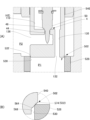
[変形例]
図10は、変形例に係るシールリングの構造を表す部分拡大図である。図10(A)は変形例1、図10(B)は変形例2、図10(C)は変形例3をそれぞれ示す。
これらの変形例に係るシールリングは、いずれも多角形状の断面を有する。いずれの変形例も、シールリングとガイド孔との接触面積が、シール収容部の低圧側面とシールリングとの接触面積よりも小さい。
[Modification]
10A to 10C are partial enlarged views showing the structure of a seal ring according to modified examples, in which Fig. 10A shows modified example 1, Fig. 10B shows modified example 2, and Fig. 10C shows modified example 3.
The seal rings according to these modifications all have a polygonal cross section. In all modifications, the contact area between the seal ring and the guide hole is smaller than the contact area between the seal ring and the low pressure side surface of the seal receiving portion.
変形例1のシールリング310は、段付長方形状の断面を有し、下部より上部の外径が小さくされている(図10(A))。すなわち、シールリング310は、小径部312(上部)と大径部314(下部)を有し、大径部314においてガイド孔38に摺動する。小径部312を残すことでシールリング310の剛性を確保しつつ、摺動部を大径部314に制限することで、摺動抵抗を小さく抑えることができる。
The
変形例2のシールリング320は、変形例1の大径部314に対応し、高さが小さい長方形状の断面を有する(図10(B))。このような構成としても、ガイド孔38との摺動面積が小さいため、摺動抵抗を小さく抑えることができる。
The
変形例3のシールリング330は、概ね菱形形状であって外周部と内周部が径方向にやや突出した断面形状を有する。シール収容部322の低圧側面334には、シールリング330の下面と相補形状の環状溝が形成されている。菱形形状としたことで変形例1と同程度の断面積を有し、剛性を確保できる。また、シールリング330の下面と低圧側面334とを相補形状とすることで、シールリング330を安定に保持し、良好なシール性能を確保できる。
The
図11は、他の変形例に係るシールリングの構造を表す部分拡大図である。図11(A)は変形例4、図11(B)は変形例5をそれぞれ示す。各図において、上段はシールリングに差圧が作用していない状態を示す。下段はシールリングに差圧が作用したときの挙動を模式的に示す。 Figure 11 is a partially enlarged view showing the structure of a seal ring according to another modified example. Figure 11(A) shows modified example 4, and Figure 11(B) shows modified example 5. In each figure, the upper part shows the state when no differential pressure acts on the seal ring. The lower part shows a schematic of the behavior when a differential pressure acts on the seal ring.
変形例4のシールリング340は、頂点がR面取りされた正三角形状の断面を有する(図11(A)上段)。シールリング340の上面342と下面344が傾斜面(テーパ面)とされている。シールリング340に差圧(P1-P2)が作用すると、その差圧の軸線方向成分が下方に作用する(図11(A)下段)。このため、シールリング340の断面に回転モーメント又は曲げモーメントが作用する(二点鎖線矢印参照)。その結果、シールリング340の断面が変形する。シールリング340とガイド孔38との接触面積は、シール収容部122の低圧側面144とシールリング340との接触面積よりも小さくなる。それにより、第1弁体40をその摺動抵抗を小さく抑えつつ、ガイド孔38に沿って安定に摺動させることができる。
The
変形例5のシールリング350は、上記実施形態のシールリング124を上下反転させたものであり、直角三角形状の断面を有する(図11(B)上段)。シールリング350に差圧(P1-P2)が作用すると、その差圧の軸線方向成分が下方に作用する(図11(B)下段)。このため、変形例4と同様に、シールリング350の断面に回転モーメント又は曲げモーメントが作用する(二点鎖線矢印参照)。その結果、シールリング350とガイド孔38との接触面積が、シール収容部122の低圧側面144とシールリング350との接触面積よりも小さくなる。それにより、第1弁体40をその摺動抵抗を小さく抑えつつ、ガイド孔38に沿って安定に摺動させることができる。
The
図12は、差圧によるシールリングの変形を解析した結果を表す図である。図12(A)は変形例4の解析結果、図12(B)は変形例5の解析結果をそれぞれ示す。各図において、上段から下段に向けて差圧(P1-P2)が大きくなっている。
Figure 12 shows the results of an analysis of the deformation of the seal ring due to differential pressure. Figure 12(A) shows the analysis results for
本解析により、変形例4において、その差圧によりシールリング340の変形が生じ、シールリング340のガイド孔38との接触面積が、低圧側面144との接触面積よりも小さくなっていることが分かる。シールリング340の変形後の摺動面圧(摺動抵抗)も小さく抑えられている(図12(A))。変形例5においても同様に、その差圧によりシールリング350の変形が生じ、シールリング350のガイド孔38との接触面積が、低圧側面144との接触面積よりも小さくなっている。シールリング350の変形後の摺動面圧(摺動抵抗)も小さく抑えられている(図12(B))。
This analysis shows that in
図13は、他の変形例に係るシール構造を表す部分拡大図である。図13(A)はシールリングおよびその周辺の構成を表す部分拡大断面図であり、図13(B)は図13(A)のD部拡大図である。 Figure 13 is a partially enlarged view showing a seal structure relating to another modified example. Figure 13(A) is a partially enlarged cross-sectional view showing the configuration of the seal ring and its surroundings, and Figure 13(B) is an enlarged view of part D in Figure 13(A).
図13(A)に示すように、本変形例では、シール収容部422が第1弁体440の外周面ではなくガイド孔438の内周面に設けられ、シールリング424が嵌着されている。図13(B)にも示すように、シール収容部422は、底面441と高圧側面442と低圧側面444を有する環状の凹部である。
As shown in FIG. 13(A), in this modified example, the
一方、シールリング424は、頂点がR面取りされた直角三角形状の断面を有する。シールリング424の外周面446が平坦面とされ、その外周面446と直角をなす下面448が、シール収容部422の低圧側面444に当接する。シールリング424の上面450が傾斜面(テーパ面)とされ、上面450と下面448とがつながる頂部によりシールリング424の内周面452が構成される。第1弁体440がガイド孔438に沿って摺動する際、第1弁体440の外周面がシールリング424の内周面452に密着摺動することでシール性が確保される。シール収容部422の底面441とシールリング424の外周面446との間(底面441とシールリング424との対向面の間)には空隙Sが形成される。
On the other hand, the
このような構成においても、シールリング424は、第1弁体440の外周面との接触面積が、シール収容部422の低圧側面444との接触面積よりも小さくなる。すなわち、Oリング等の場合と比較してシールリング424と第1弁体440との摺動面積を小さくでき、第1弁体440の摺動抵抗を低減できる。
Even in this configuration, the contact area of the
図14は、他の変形例に係る第1弁の構成を表す部分拡大図である。図14(A)は第1弁およびその周辺の構成を表す部分拡大断面図であり、図14(B)は図14(A)のF部拡大図である。 Figure 14 is a partially enlarged view showing the configuration of the first valve according to another modified example. Figure 14(A) is a partially enlarged cross-sectional view showing the configuration of the first valve and its surroundings, and Figure 14(B) is an enlarged view of part F in Figure 14(A).
図14(A)に示すように、本変形例では、第1弁502における第1弁体540と弁座形成部材528との着脱構造が上記実施形態とは異なる。図14(B)にも示すように、弁座形成部材28の上端開口部がエッジ部574となっており、そのエッジ部574が第1弁座532を構成する。一方、第1弁体540の先端部がテーパ面564とストレート部568を有する。ストレート部568は、第1弁体540の軸線に平行である。
As shown in FIG. 14(A), in this modified example, the attachment/detachment structure between the
すなわち、第1弁502は、その開閉構造として、ストレート部568が第1弁孔530に同軸状に挿抜される挿抜構造と、ストレート部568が第1弁孔530に挿入された状態でテーパ面564がエッジ部574に着脱する着脱構造を有する。それにより、第1弁502の閉弁および寸開状態において第1弁体540の先端部と第1弁孔530との間に微小なクリアランスが形成される。
That is, the
このため、上記実施形態と同様に、第1弁体540において開弁直後の受圧面の減少を抑制できる。その結果、第1弁体540に作用する閉弁方向の荷重を小さくでき、モータの負荷を抑えることができる。
As a result, as in the above embodiment, the reduction in the pressure-receiving surface area of the
なお、本変形例では図示しないが、第1弁体540における少なくともテーパ面564にゴムの焼き付けを施してもよい。また、弁座形成部材528における少なくともエッジ部574およびその近傍にゴムの焼き付けを施してもよい。それにより、第1弁座532の耐久性を高めることができ、第1弁502のシール性を向上させることができる。
Although not shown in this modified example, at least the
[その他の変形例]
上記実施形態および変形例では、シールリングの断面形状について例示したが、上記以外の断面多角形状を採用してもよい。ただし、シールリングは、弁体の外周面およびガイド孔の内周面の一方に設けられた環状の凹部に嵌着され、弁体の外周面およびガイド孔の内周面の他方との接触面積が、シール収容部(凹部)の低圧側面との接触面積よりも小さくなるようにする。差圧により弁体の外周面およびガイド孔の内周面の他方との接触面積が、凹部の低圧側面との接触面積よりも小さくなるものでもよい。
[Other Modifications]
In the above embodiment and modified example, the cross-sectional shape of the seal ring is exemplified, but a cross-sectional polygonal shape other than the above may be adopted. However, the seal ring is fitted into an annular recess provided on one of the outer peripheral surface of the valve body and the inner peripheral surface of the guide hole, so that the contact area between the other of the outer peripheral surface of the valve body and the inner peripheral surface of the guide hole is smaller than the contact area with the low pressure side of the seal accommodating portion (recess). The contact area between the other of the outer peripheral surface of the valve body and the inner peripheral surface of the guide hole due to the pressure difference may be smaller than the contact area with the low pressure side of the recess.
上記実施形態では、第1弁孔30として二段テーパ構造を例示したが、一段テーパとしつつストレート部を有する構造としてもよい。具体的には、図4(B)に示した第1テーパ面164を有するが、第2テーパ面166を有しない構造を採用してもよい。
In the above embodiment, a two-stage tapered structure is exemplified for the
上記実施形態では、複数の弁(第1弁および第2弁)を同軸状に備える複合弁を例示した。変形例においては、単一の弁を備える電動弁としてもよい。その場合も、シールリングは、弁体の外周面およびガイド孔の内周面の一方に設けられた環状の凹部に嵌着され、弁体の外周面およびガイド孔の内周面の他方との接触面積が、シール収容部(凹部)の低圧側面との接触面積よりも小さくなるようにする。 In the above embodiment, a composite valve having multiple valves (first valve and second valve) arranged coaxially is exemplified. In a modified example, a motor-operated valve having a single valve may be used. In this case, too, the seal ring is fitted into an annular recess provided on one of the outer circumferential surface of the valve body and the inner circumferential surface of the guide hole, so that the contact area with the other of the outer circumferential surface of the valve body and the inner circumferential surface of the guide hole is smaller than the contact area with the low-pressure side of the seal accommodating portion (recess).
上記実施形態では、第1弁体40を閉弁方向に付勢する付勢部材としてスプリング58を例示したが、ゴムその他の弾性体としてもよい。
In the above embodiment, the
上記実施形態では、極歯を有するヨークを含むステータとした。変形例においては、積層コアを含むステータなどでもよい。 In the above embodiment, the stator includes a yoke having pole teeth. In a modified example, the stator may include a laminated core.
上記実施形態では、上記電動弁を膨張弁として構成したが、膨張機能を有しない開閉弁や電磁弁等制御弁であればよい。また、上記実施形態では、アクチュエータとしてモータを例示したが、ソレノイドその他のアクチュエータを採用してもよい。 In the above embodiment, the motor-operated valve is configured as an expansion valve, but it may be any control valve such as an on-off valve or solenoid valve that does not have an expansion function. Also, in the above embodiment, a motor is used as an example of an actuator, but a solenoid or other actuator may be used.
上記実施形態の電動弁は、冷媒として代替フロン(HFC-134a)など使用する冷凍サイクルに好適に適用されるが、二酸化炭素のように作動圧力が高い冷媒を用いる冷凍サイクルに適用することも可能である。その場合には、冷凍サイクルにコンデンサに代わってガスクーラなどの外部熱交換器が配置される。 The motor-operated valve of the above embodiment is preferably applied to a refrigeration cycle that uses a refrigerant such as a fluorocarbon alternative (HFC-134a) as a refrigerant, but it can also be applied to a refrigeration cycle that uses a refrigerant with a high operating pressure such as carbon dioxide. In that case, an external heat exchanger such as a gas cooler is placed in the refrigeration cycle instead of a condenser.
上記実施形態では、上記電動弁を自動車用空調装置の冷凍サイクルに適用する例を示したが、車両用に限らず電動膨張弁を搭載する空調装置に適用可能である。また、給湯装置や油圧制御装置など冷媒以外の流体の流れを制御する電動弁として構成してもよい。 In the above embodiment, an example was shown in which the motorized valve was applied to the refrigeration cycle of an automotive air conditioner, but the motorized valve can be applied to any air conditioner equipped with an electric expansion valve, not limited to vehicles. It may also be configured as a motorized valve for controlling the flow of fluids other than refrigerant, such as in a hot water supply device or hydraulic control device.
なお、本発明は上記実施形態や変形例に限定されるものではなく、要旨を逸脱しない範囲で構成要素を変形して具体化することができる。上記実施形態や変形例に開示されている複数の構成要素を適宜組み合わせることにより種々の発明を形成してもよい。また、上記実施形態や変形例に示される全構成要素からいくつかの構成要素を削除してもよい。 The present invention is not limited to the above-described embodiments and modifications, and can be embodied by modifying the components without departing from the spirit of the invention. Various inventions may be formed by appropriately combining multiple components disclosed in the above-described embodiments and modifications. In addition, some components may be deleted from all the components shown in the above-described embodiments and modifications.
1 電動弁、2 第1弁、4 第2弁、6 弁本体、8 モータユニット、10 ボディ、16 ガイド部材、18 導入ポート、20 導出ポート、28 弁座形成部材、30 第1弁孔、32 第1弁座、38 ガイド孔、40 第1弁体、42 内部通路、44 第2弁孔、46 第2弁座、48 作動ロッド、50 第2弁体、60 ロータ、62 回転軸、64 ステータ、90 ねじ送り機構、108 背圧室、110 弁室、112 作動連結部材、122 シール収容部、124 シールリング、126 拡径部、130 連通孔、132 入口ポート、134 下流側通路、136 出口ポート、140 底面、142 高圧側面、144 低圧側面、146 内周面、152 外周面、162 ゴム、164 第1テーパ面、166 第2テーパ面、168 ストレート部、170 段差部、172 小径部、174 エッジ部、202 第1弁、224 Oリング、230 第1弁孔、310 シールリング、312 小径部、314 大径部、320 シールリング、322 シール収容部、330 シールリング、334 低圧側面、340 シールリング、350 シールリング、422 シール収容部、424 シールリング、438 ガイド孔、440 第1弁体、442 高圧側面、444 低圧側面、446 外周面、452 内周面、502 第1弁、528 弁座形成部材、530 第1弁孔、532 第1弁座、540 第1弁体、564 テーパ面、568 ストレート部、574 エッジ部、S 空隙。 1 Electric valve, 2 First valve, 4 Second valve, 6 Valve body, 8 Motor unit, 10 Body, 16 Guide member, 18 Inlet port, 20 Outlet port, 28 Valve seat forming member, 30 First valve hole, 32 First valve seat, 38 Guide hole, 40 First valve body, 42 Internal passage, 44 Second valve hole, 46 Second valve seat, 48 Actuating rod, 50 Second valve body, 60 Rotor, 62 Rotating shaft, 64 Stator, 90 Screw feed mechanism, 108 Back pressure chamber, 110 Valve chamber, 112 Actuating connecting member, 122 Seal accommodating portion, 124 Seal ring, 126 Enlarged diameter portion, 130 Communication hole, 132 Inlet port, 134 Downstream passage, 136 Outlet port, 140 Bottom surface, 142 High pressure side, 144 Low pressure side, 146 Inner peripheral surface, 152 Outer peripheral surface, 162 Rubber, 164 First tapered surface, 166 Second tapered surface, 168 Straight portion, 170 Step portion, 172 Small diameter portion, 174 Edge portion, 202 First valve, 224 O-ring, 230 First valve hole, 310 Seal ring, 312 Small diameter portion, 314 Large diameter portion, 320 Seal ring, 322 Seal accommodating portion, 330 Seal ring, 334 Low pressure side surface, 340 Seal ring, 350 Seal ring, 422 Seal accommodating portion, 424 Seal ring, 438 Guide hole, 440 First valve body, 442 High pressure side surface, 444 Low pressure side surface, 446 Outer peripheral surface, 452 Inner peripheral surface, 502 First valve, 528 Valve seat forming member, 530 First valve hole, 532 First valve seat, 540 first valve body, 564 tapered surface, 568 straight portion, 574 edge portion, S gap.
Claims (6)
前記弁座に下流側から着脱して弁部を開閉する弁体と、
前記弁体を前記弁部の開閉方向に駆動するアクチュエータと、
を備え、
前記弁部の開閉構造は、
前記弁体の先端部が前記弁孔に同軸状に挿抜される挿抜構造と、
前記弁体の先端部が前記弁孔に挿入された状態で、前記弁体および前記弁座の一方のエッジ部と他方のテーパ面とが着脱する着脱構造と、
を含み、
前記着脱構造は、前記弁座として機能する第1テーパ面と、前記弁体の先端に設けられた前記エッジ部とを含み、
前記挿抜構造は、前記弁孔の開口端を形成する第2テーパ面を含み、
前記弁孔は、前記第1テーパ面と前記第2テーパ面との間に前記弁体の軸線に平行なストレート部を含む二段テーパ構造を有することを特徴とする制御弁。 a body having an inlet port for introducing a fluid, an outlet port for discharging the fluid, a valve hole for communicating the inlet port with the outlet port, and a valve seat provided in the valve hole;
a valve body that is attached to and detached from the valve seat from a downstream side to open and close the valve portion;
an actuator that drives the valve body in an opening/closing direction of the valve portion;
Equipped with
The opening and closing structure of the valve portion is
an insertion/removal structure in which a tip portion of the valve body is inserted and removed coaxially into the valve hole;
a detachable structure for attaching and detaching the edge portion of the valve body and the valve seat to and from the tapered surface of the other side in a state where the tip portion of the valve body is inserted into the valve hole;
Including,
the detachable structure includes a first tapered surface that functions as the valve seat and the edge portion that is provided at a tip of the valve body,
the insertion/removal structure includes a second tapered surface forming an opening end of the valve hole,
The valve hole has a two-stage tapered structure including a straight portion parallel to an axis of the valve body between the first tapered surface and the second tapered surface .
前記弁座に下流側から着脱して弁部を開閉する弁体と、
前記弁体を前記弁部の開閉方向に駆動するアクチュエータと、
を備え、
前記弁部の開閉構造は、
前記弁体の先端部が前記弁孔に同軸状に挿抜される挿抜構造と、
前記弁体の先端部が前記弁孔に挿入された状態で、前記弁体および前記弁座の一方のエッジ部と他方のテーパ面とが着脱する着脱構造と、
を含み、
前記着脱構造は、前記弁孔の開口端に形成され前記弁座として機能する前記エッジ部と、前記弁体の先端部に形成された前記テーパ面とを含み、
前記挿抜構造は、前記弁体の前記テーパ面よりも先端側に連続して形成され、前記弁体の軸線に平行なストレート部を含むことを特徴とする制御弁。 a body having an inlet port for introducing a fluid, an outlet port for discharging the fluid, a valve hole for communicating the inlet port with the outlet port, and a valve seat provided in the valve hole;
a valve body that is attached to and detached from the valve seat from a downstream side to open and close the valve portion;
an actuator that drives the valve body in an opening/closing direction of the valve portion;
Equipped with
The opening and closing structure of the valve portion is
an insertion/removal structure in which a tip portion of the valve body is inserted and removed coaxially into the valve hole;
a detachable structure for attaching and detaching the edge portion of the valve body and the valve seat to and from the tapered surface of the other side in a state where the tip portion of the valve body is inserted into the valve hole;
Including,
the detachable structure includes the edge portion formed at an open end of the valve hole and functioning as the valve seat, and the tapered surface formed at a tip end of the valve body,
The control valve is characterized in that the insertion/removal structure includes a straight portion that is formed continuously with the tapered surface of the valve body toward the tip side and is parallel to the axis of the valve body .
前記弁座の上流側と前記背圧室とを連通させる連通路が設けられることで、前記弁体に作用する流体の圧力の少なくとも一部がキャンセルされる一方、
閉弁時に前記弁体に閉弁方向の差圧が作用するよう前記弁体のシール部径が設定されていることを特徴とする請求項1又は2に記載の制御弁。 A back pressure chamber is formed on the valve body on the opposite side to the valve hole.
By providing a communication passage that communicates the upstream side of the valve seat with the back pressure chamber, at least a part of the fluid pressure acting on the valve body is canceled.
3. The control valve according to claim 1, wherein a diameter of a seal portion of the valve body is set so that a pressure difference in a valve closing direction acts on the valve body when the valve is closed.
前記弁体を閉弁方向に付勢する付勢部材と、
前記作動ロッドと前記弁体とを一体変位可能に作動連結する作動連結機構と、
をさらに備えることを特徴とする請求項1~3のいずれかに記載の制御弁。 an actuation rod for transmitting an axial driving force from the actuator;
A biasing member that biases the valve body in a valve closing direction;
an operational connection mechanism that operationally connects the operating rod and the valve body so as to be displaceable together;
The control valve according to any one of claims 1 to 3, further comprising:
前記弁孔と同軸状に設けられたガイド孔を有する前記ボディと、
前記ガイド孔に摺動可能に支持され、前記弁座に着脱する前記弁体と、
前記アクチュエータとして、前記弁体を駆動するためのロータを含むモータと、
前記ロータの回転運動を前記作動ロッドの並進運動に変換するねじ送り機構と、
を備えることを特徴とする請求項4に記載の制御弁。 It is configured as an electric valve,
the body having a guide hole provided coaxially with the valve hole;
The valve body is slidably supported in the guide hole and is detachably attached to the valve seat;
a motor including a rotor for driving the valve body as the actuator;
a screw feed mechanism for converting the rotational motion of the rotor into the translational motion of the actuation rod;
5. The control valve of claim 4, further comprising:
前記弁体として、前記導入ポートに連通する入口ポートと、前記導出ポートに連通する出口ポートと、前記入口ポートと前記出口ポートとをつなぐ通路に前記第1弁孔と同軸状に設けられた第2弁孔とを有し、前記ガイド孔に摺動可能に支持され、前記弁座に着脱して第1弁を開閉する第1弁体と、
前記作動ロッドに一体に設けられ、前記第1弁体に同軸状に挿通され、前記第2弁孔に接離して第2弁を開閉する第2弁体と、
を備え、
前記作動連結機構は、前記第2弁体の前記第2弁孔からのリフト量が所定値以上となったときに前記第1弁体と前記第2弁体とを一体変位可能に作動連結することを特徴とする請求項5に記載の制御弁。 the body having a first valve hole as the valve hole;
the valve body having an inlet port communicating with the introduction port, an outlet port communicating with the discharge port, and a second valve hole provided coaxially with the first valve hole in a passage connecting the inlet port and the outlet port, the first valve body being slidably supported in the guide hole and being detachably attached to the valve seat to open and close the first valve;
a second valve body that is integral with the actuation rod, that is coaxially inserted through the first valve body, and that moves toward and away from the second valve hole to open and close the second valve;
Equipped with
6. The control valve according to claim 5, wherein the operational connection mechanism operationally connects the first valve body and the second valve body so as to be displaceable together when a lift amount of the second valve body from the second valve hole becomes equal to or greater than a predetermined value .
Priority Applications (3)
| Application Number | Priority Date | Filing Date | Title |
|---|---|---|---|
| JP2021047608A JP7587828B2 (en) | 2021-03-22 | 2021-03-22 | Control valve |
| EP23163087.2A EP4220038A1 (en) | 2021-03-22 | 2022-03-21 | Control valve |
| EP22163335.7A EP4063765A1 (en) | 2021-03-22 | 2022-03-21 | Control valve |
Applications Claiming Priority (1)
| Application Number | Priority Date | Filing Date | Title |
|---|---|---|---|
| JP2021047608A JP7587828B2 (en) | 2021-03-22 | 2021-03-22 | Control valve |
Publications (2)
| Publication Number | Publication Date |
|---|---|
| JP2022146573A JP2022146573A (en) | 2022-10-05 |
| JP7587828B2 true JP7587828B2 (en) | 2024-11-21 |
Family
ID=80928855
Family Applications (1)
| Application Number | Title | Priority Date | Filing Date |
|---|---|---|---|
| JP2021047608A Active JP7587828B2 (en) | 2021-03-22 | 2021-03-22 | Control valve |
Country Status (2)
| Country | Link |
|---|---|
| EP (2) | EP4063765A1 (en) |
| JP (1) | JP7587828B2 (en) |
Families Citing this family (1)
| Publication number | Priority date | Publication date | Assignee | Title |
|---|---|---|---|---|
| WO2025210991A1 (en) * | 2024-04-01 | 2025-10-09 | 株式会社不二工機 | Electric valve, valve device, and method for manufacturing stator unit |
Citations (2)
| Publication number | Priority date | Publication date | Assignee | Title |
|---|---|---|---|---|
| JP2020041596A (en) | 2018-09-10 | 2020-03-19 | 株式会社テージーケー | Motor-operated valve |
| CN111608980A (en) | 2020-06-07 | 2020-09-01 | 杨新超 | Differential pressure compensation valve with fast and stable main valve opening |
Family Cites Families (7)
| Publication number | Priority date | Publication date | Assignee | Title |
|---|---|---|---|---|
| US2594393A (en) * | 1948-11-09 | 1952-04-29 | Detroit Lubricator Co | Pressure limiting means for liquid charged refrigeration expansion valves |
| JPH0665915B2 (en) * | 1987-03-27 | 1994-08-24 | 株式会社鷺宮製作所 | Reversible electric expansion valve |
| JPH04111966U (en) * | 1991-03-19 | 1992-09-29 | シーケーデイ株式会社 | flow regulating valve |
| JP2898906B2 (en) * | 1995-06-29 | 1999-06-02 | 株式会社不二工機 | Electric flow control valve |
| JP4285156B2 (en) * | 2003-08-27 | 2009-06-24 | ダイキン工業株式会社 | Multistage electric expansion valve and refrigeration system |
| JP4255807B2 (en) * | 2003-11-06 | 2009-04-15 | 株式会社不二工機 | Expansion valve with electromagnetic relief valve |
| US20120126161A1 (en) * | 2010-09-01 | 2012-05-24 | Amir Jeshani | Valve |
-
2021
- 2021-03-22 JP JP2021047608A patent/JP7587828B2/en active Active
-
2022
- 2022-03-21 EP EP22163335.7A patent/EP4063765A1/en active Pending
- 2022-03-21 EP EP23163087.2A patent/EP4220038A1/en active Pending
Patent Citations (2)
| Publication number | Priority date | Publication date | Assignee | Title |
|---|---|---|---|---|
| JP2020041596A (en) | 2018-09-10 | 2020-03-19 | 株式会社テージーケー | Motor-operated valve |
| CN111608980A (en) | 2020-06-07 | 2020-09-01 | 杨新超 | Differential pressure compensation valve with fast and stable main valve opening |
Also Published As
| Publication number | Publication date |
|---|---|
| JP2022146573A (en) | 2022-10-05 |
| EP4220038A1 (en) | 2023-08-02 |
| EP4063765A1 (en) | 2022-09-28 |
Similar Documents
| Publication | Publication Date | Title |
|---|---|---|
| JP6281046B2 (en) | Control valve for variable capacity compressor | |
| JP5906372B2 (en) | Control valve | |
| KR20120089837A (en) | Control valve for variable displacement compressor | |
| JP2011043102A (en) | Control valve for variable displacement compressor | |
| JP7107881B2 (en) | Electric valve and refrigeration cycle system | |
| JP7587828B2 (en) | Control valve | |
| JP7603976B2 (en) | Control valve | |
| JP2002295709A (en) | Flow rate control valve | |
| JP7555118B2 (en) | Control valve | |
| JP2011038630A (en) | Solenoid valve | |
| JP2011149505A (en) | Motor-operated valve | |
| JP7481562B2 (en) | Motor-operated valve and refrigeration cycle system | |
| JP2021179240A (en) | Motor-operated valve and refrigeration cycle system | |
| JP2000266194A (en) | Two-stage electric expansion valve | |
| JP6040343B2 (en) | solenoid valve | |
| CN115126885B (en) | Electric valve | |
| JP6040371B2 (en) | Control valve | |
| JP2009299674A (en) | Control valve unit and connector | |
| JP7242511B2 (en) | Electric valve and refrigeration cycle system | |
| JP2010196794A (en) | Solenoid valve | |
| JP2025015423A (en) | Electric valve | |
| JP2010024874A (en) | Variable displacement compressor control valve | |
| JP2025130738A (en) | Electric valve | |
| CN114838180B (en) | Electric valve | |
| JP2024071877A (en) | Motor-operated valve |
Legal Events
| Date | Code | Title | Description |
|---|---|---|---|
| A621 | Written request for application examination |
Free format text: JAPANESE INTERMEDIATE CODE: A621 Effective date: 20231102 |
|
| A977 | Report on retrieval |
Free format text: JAPANESE INTERMEDIATE CODE: A971007 Effective date: 20240620 |
|
| A131 | Notification of reasons for refusal |
Free format text: JAPANESE INTERMEDIATE CODE: A131 Effective date: 20240702 |
|
| A521 | Request for written amendment filed |
Free format text: JAPANESE INTERMEDIATE CODE: A523 Effective date: 20240726 |
|
| TRDD | Decision of grant or rejection written | ||
| A01 | Written decision to grant a patent or to grant a registration (utility model) |
Free format text: JAPANESE INTERMEDIATE CODE: A01 Effective date: 20241022 |
|
| A61 | First payment of annual fees (during grant procedure) |
Free format text: JAPANESE INTERMEDIATE CODE: A61 Effective date: 20241101 |
|
| R150 | Certificate of patent or registration of utility model |
Ref document number: 7587828 Country of ref document: JP Free format text: JAPANESE INTERMEDIATE CODE: R150 |