JP7586897B2 - Apparatus and method for improved assisted ventilation - Patents.com - Google Patents
Apparatus and method for improved assisted ventilation - Patents.com Download PDFInfo
- Publication number
- JP7586897B2 JP7586897B2 JP2022514213A JP2022514213A JP7586897B2 JP 7586897 B2 JP7586897 B2 JP 7586897B2 JP 2022514213 A JP2022514213 A JP 2022514213A JP 2022514213 A JP2022514213 A JP 2022514213A JP 7586897 B2 JP7586897 B2 JP 7586897B2
- Authority
- JP
- Japan
- Prior art keywords
- ventilation
- lumen
- pressure
- patient
- tube
- Prior art date
- Legal status (The legal status is an assumption and is not a legal conclusion. Google has not performed a legal analysis and makes no representation as to the accuracy of the status listed.)
- Active
Links
Images


Classifications
-
- A—HUMAN NECESSITIES
- A61—MEDICAL OR VETERINARY SCIENCE; HYGIENE
- A61M—DEVICES FOR INTRODUCING MEDIA INTO, OR ONTO, THE BODY; DEVICES FOR TRANSDUCING BODY MEDIA OR FOR TAKING MEDIA FROM THE BODY; DEVICES FOR PRODUCING OR ENDING SLEEP OR STUPOR
- A61M16/00—Devices for influencing the respiratory system of patients by gas treatment, e.g. ventilators; Tracheal tubes
- A61M16/021—Devices for influencing the respiratory system of patients by gas treatment, e.g. ventilators; Tracheal tubes operated by electrical means
- A61M16/022—Control means therefor
- A61M16/024—Control means therefor including calculation means, e.g. using a processor
-
- A—HUMAN NECESSITIES
- A61—MEDICAL OR VETERINARY SCIENCE; HYGIENE
- A61B—DIAGNOSIS; SURGERY; IDENTIFICATION
- A61B5/00—Measuring for diagnostic purposes; Identification of persons
- A61B5/08—Measuring devices for evaluating the respiratory organs
- A61B5/087—Measuring breath flow
-
- A—HUMAN NECESSITIES
- A61—MEDICAL OR VETERINARY SCIENCE; HYGIENE
- A61B—DIAGNOSIS; SURGERY; IDENTIFICATION
- A61B5/00—Measuring for diagnostic purposes; Identification of persons
- A61B5/08—Measuring devices for evaluating the respiratory organs
- A61B5/097—Devices for facilitating collection of breath or for directing breath into or through measuring devices
-
- A—HUMAN NECESSITIES
- A61—MEDICAL OR VETERINARY SCIENCE; HYGIENE
- A61B—DIAGNOSIS; SURGERY; IDENTIFICATION
- A61B5/00—Measuring for diagnostic purposes; Identification of persons
- A61B5/48—Other medical applications
- A61B5/4836—Diagnosis combined with treatment in closed-loop systems or methods
-
- A—HUMAN NECESSITIES
- A61—MEDICAL OR VETERINARY SCIENCE; HYGIENE
- A61M—DEVICES FOR INTRODUCING MEDIA INTO, OR ONTO, THE BODY; DEVICES FOR TRANSDUCING BODY MEDIA OR FOR TAKING MEDIA FROM THE BODY; DEVICES FOR PRODUCING OR ENDING SLEEP OR STUPOR
- A61M16/00—Devices for influencing the respiratory system of patients by gas treatment, e.g. ventilators; Tracheal tubes
- A61M16/04—Tracheal tubes
- A61M16/0402—Special features for tracheal tubes not otherwise provided for
- A61M16/0411—Special features for tracheal tubes not otherwise provided for with means for differentiating between oesophageal and tracheal intubation
-
- A—HUMAN NECESSITIES
- A61—MEDICAL OR VETERINARY SCIENCE; HYGIENE
- A61M—DEVICES FOR INTRODUCING MEDIA INTO, OR ONTO, THE BODY; DEVICES FOR TRANSDUCING BODY MEDIA OR FOR TAKING MEDIA FROM THE BODY; DEVICES FOR PRODUCING OR ENDING SLEEP OR STUPOR
- A61M16/00—Devices for influencing the respiratory system of patients by gas treatment, e.g. ventilators; Tracheal tubes
- A61M16/04—Tracheal tubes
- A61M16/0434—Cuffs
-
- A—HUMAN NECESSITIES
- A61—MEDICAL OR VETERINARY SCIENCE; HYGIENE
- A61M—DEVICES FOR INTRODUCING MEDIA INTO, OR ONTO, THE BODY; DEVICES FOR TRANSDUCING BODY MEDIA OR FOR TAKING MEDIA FROM THE BODY; DEVICES FOR PRODUCING OR ENDING SLEEP OR STUPOR
- A61M16/00—Devices for influencing the respiratory system of patients by gas treatment, e.g. ventilators; Tracheal tubes
- A61M16/04—Tracheal tubes
- A61M16/0463—Tracheal tubes combined with suction tubes, catheters or the like; Outside connections
-
- A—HUMAN NECESSITIES
- A61—MEDICAL OR VETERINARY SCIENCE; HYGIENE
- A61M—DEVICES FOR INTRODUCING MEDIA INTO, OR ONTO, THE BODY; DEVICES FOR TRANSDUCING BODY MEDIA OR FOR TAKING MEDIA FROM THE BODY; DEVICES FOR PRODUCING OR ENDING SLEEP OR STUPOR
- A61M16/00—Devices for influencing the respiratory system of patients by gas treatment, e.g. ventilators; Tracheal tubes
- A61M16/04—Tracheal tubes
- A61M16/0475—Tracheal tubes having openings in the tube
-
- A—HUMAN NECESSITIES
- A61—MEDICAL OR VETERINARY SCIENCE; HYGIENE
- A61M—DEVICES FOR INTRODUCING MEDIA INTO, OR ONTO, THE BODY; DEVICES FOR TRANSDUCING BODY MEDIA OR FOR TAKING MEDIA FROM THE BODY; DEVICES FOR PRODUCING OR ENDING SLEEP OR STUPOR
- A61M16/00—Devices for influencing the respiratory system of patients by gas treatment, e.g. ventilators; Tracheal tubes
- A61M16/06—Respiratory or anaesthetic masks
-
- A—HUMAN NECESSITIES
- A61—MEDICAL OR VETERINARY SCIENCE; HYGIENE
- A61M—DEVICES FOR INTRODUCING MEDIA INTO, OR ONTO, THE BODY; DEVICES FOR TRANSDUCING BODY MEDIA OR FOR TAKING MEDIA FROM THE BODY; DEVICES FOR PRODUCING OR ENDING SLEEP OR STUPOR
- A61M16/00—Devices for influencing the respiratory system of patients by gas treatment, e.g. ventilators; Tracheal tubes
- A61M16/20—Valves specially adapted to medical respiratory devices
- A61M16/201—Controlled valves
- A61M16/202—Controlled valves electrically actuated
-
- A—HUMAN NECESSITIES
- A61—MEDICAL OR VETERINARY SCIENCE; HYGIENE
- A61M—DEVICES FOR INTRODUCING MEDIA INTO, OR ONTO, THE BODY; DEVICES FOR TRANSDUCING BODY MEDIA OR FOR TAKING MEDIA FROM THE BODY; DEVICES FOR PRODUCING OR ENDING SLEEP OR STUPOR
- A61M16/00—Devices for influencing the respiratory system of patients by gas treatment, e.g. ventilators; Tracheal tubes
- A61M16/20—Valves specially adapted to medical respiratory devices
- A61M16/208—Non-controlled one-way valves, e.g. exhalation, check, pop-off non-rebreathing valves
- A61M16/209—Relief valves
-
- A—HUMAN NECESSITIES
- A61—MEDICAL OR VETERINARY SCIENCE; HYGIENE
- A61B—DIAGNOSIS; SURGERY; IDENTIFICATION
- A61B2562/00—Details of sensors; Constructional details of sensor housings or probes; Accessories for sensors
- A61B2562/02—Details of sensors specially adapted for in-vivo measurements
- A61B2562/0247—Pressure sensors
-
- A—HUMAN NECESSITIES
- A61—MEDICAL OR VETERINARY SCIENCE; HYGIENE
- A61B—DIAGNOSIS; SURGERY; IDENTIFICATION
- A61B5/00—Measuring for diagnostic purposes; Identification of persons
- A61B5/03—Measuring fluid pressure within the body other than blood pressure, e.g. cerebral pressure ; Measuring pressure in body tissues or organs
- A61B5/036—Measuring fluid pressure within the body other than blood pressure, e.g. cerebral pressure ; Measuring pressure in body tissues or organs by means introduced into body tracts
-
- A—HUMAN NECESSITIES
- A61—MEDICAL OR VETERINARY SCIENCE; HYGIENE
- A61B—DIAGNOSIS; SURGERY; IDENTIFICATION
- A61B5/00—Measuring for diagnostic purposes; Identification of persons
- A61B5/08—Measuring devices for evaluating the respiratory organs
- A61B5/091—Measuring volume of inspired or expired gases, e.g. to determine lung capacity
-
- A—HUMAN NECESSITIES
- A61—MEDICAL OR VETERINARY SCIENCE; HYGIENE
- A61B—DIAGNOSIS; SURGERY; IDENTIFICATION
- A61B5/00—Measuring for diagnostic purposes; Identification of persons
- A61B5/103—Measuring devices for testing the shape, pattern, colour, size or movement of the body or parts thereof, for diagnostic purposes
- A61B5/11—Measuring movement of the entire body or parts thereof, e.g. head or hand tremor or mobility of a limb
-
- A—HUMAN NECESSITIES
- A61—MEDICAL OR VETERINARY SCIENCE; HYGIENE
- A61M—DEVICES FOR INTRODUCING MEDIA INTO, OR ONTO, THE BODY; DEVICES FOR TRANSDUCING BODY MEDIA OR FOR TAKING MEDIA FROM THE BODY; DEVICES FOR PRODUCING OR ENDING SLEEP OR STUPOR
- A61M16/00—Devices for influencing the respiratory system of patients by gas treatment, e.g. ventilators; Tracheal tubes
- A61M16/0057—Pumps therefor
- A61M16/0063—Compressors
-
- A—HUMAN NECESSITIES
- A61—MEDICAL OR VETERINARY SCIENCE; HYGIENE
- A61M—DEVICES FOR INTRODUCING MEDIA INTO, OR ONTO, THE BODY; DEVICES FOR TRANSDUCING BODY MEDIA OR FOR TAKING MEDIA FROM THE BODY; DEVICES FOR PRODUCING OR ENDING SLEEP OR STUPOR
- A61M16/00—Devices for influencing the respiratory system of patients by gas treatment, e.g. ventilators; Tracheal tubes
- A61M16/04—Tracheal tubes
- A61M16/0402—Special features for tracheal tubes not otherwise provided for
- A61M16/0431—Special features for tracheal tubes not otherwise provided for with a cross-sectional shape other than circular
-
- A—HUMAN NECESSITIES
- A61—MEDICAL OR VETERINARY SCIENCE; HYGIENE
- A61M—DEVICES FOR INTRODUCING MEDIA INTO, OR ONTO, THE BODY; DEVICES FOR TRANSDUCING BODY MEDIA OR FOR TAKING MEDIA FROM THE BODY; DEVICES FOR PRODUCING OR ENDING SLEEP OR STUPOR
- A61M16/00—Devices for influencing the respiratory system of patients by gas treatment, e.g. ventilators; Tracheal tubes
- A61M16/04—Tracheal tubes
- A61M16/0486—Multi-lumen tracheal tubes
-
- A—HUMAN NECESSITIES
- A61—MEDICAL OR VETERINARY SCIENCE; HYGIENE
- A61M—DEVICES FOR INTRODUCING MEDIA INTO, OR ONTO, THE BODY; DEVICES FOR TRANSDUCING BODY MEDIA OR FOR TAKING MEDIA FROM THE BODY; DEVICES FOR PRODUCING OR ENDING SLEEP OR STUPOR
- A61M16/00—Devices for influencing the respiratory system of patients by gas treatment, e.g. ventilators; Tracheal tubes
- A61M16/08—Bellows; Connecting tubes ; Water traps; Patient circuits
- A61M16/0816—Joints or connectors
- A61M16/0833—T- or Y-type connectors, e.g. Y-piece
-
- A—HUMAN NECESSITIES
- A61—MEDICAL OR VETERINARY SCIENCE; HYGIENE
- A61M—DEVICES FOR INTRODUCING MEDIA INTO, OR ONTO, THE BODY; DEVICES FOR TRANSDUCING BODY MEDIA OR FOR TAKING MEDIA FROM THE BODY; DEVICES FOR PRODUCING OR ENDING SLEEP OR STUPOR
- A61M16/00—Devices for influencing the respiratory system of patients by gas treatment, e.g. ventilators; Tracheal tubes
- A61M16/0003—Accessories therefor, e.g. sensors, vibrators, negative pressure
- A61M2016/0027—Accessories therefor, e.g. sensors, vibrators, negative pressure pressure meter
-
- A—HUMAN NECESSITIES
- A61—MEDICAL OR VETERINARY SCIENCE; HYGIENE
- A61M—DEVICES FOR INTRODUCING MEDIA INTO, OR ONTO, THE BODY; DEVICES FOR TRANSDUCING BODY MEDIA OR FOR TAKING MEDIA FROM THE BODY; DEVICES FOR PRODUCING OR ENDING SLEEP OR STUPOR
- A61M2202/00—Special media to be introduced, removed or treated
- A61M2202/02—Gases
- A61M2202/0208—Oxygen
-
- A—HUMAN NECESSITIES
- A61—MEDICAL OR VETERINARY SCIENCE; HYGIENE
- A61M—DEVICES FOR INTRODUCING MEDIA INTO, OR ONTO, THE BODY; DEVICES FOR TRANSDUCING BODY MEDIA OR FOR TAKING MEDIA FROM THE BODY; DEVICES FOR PRODUCING OR ENDING SLEEP OR STUPOR
- A61M2205/00—General characteristics of the apparatus
- A61M2205/58—Means for facilitating use, e.g. by people with impaired vision
- A61M2205/581—Means for facilitating use, e.g. by people with impaired vision by audible feedback
-
- A—HUMAN NECESSITIES
- A61—MEDICAL OR VETERINARY SCIENCE; HYGIENE
- A61M—DEVICES FOR INTRODUCING MEDIA INTO, OR ONTO, THE BODY; DEVICES FOR TRANSDUCING BODY MEDIA OR FOR TAKING MEDIA FROM THE BODY; DEVICES FOR PRODUCING OR ENDING SLEEP OR STUPOR
- A61M2205/00—General characteristics of the apparatus
- A61M2205/58—Means for facilitating use, e.g. by people with impaired vision
- A61M2205/583—Means for facilitating use, e.g. by people with impaired vision by visual feedback
-
- A—HUMAN NECESSITIES
- A61—MEDICAL OR VETERINARY SCIENCE; HYGIENE
- A61M—DEVICES FOR INTRODUCING MEDIA INTO, OR ONTO, THE BODY; DEVICES FOR TRANSDUCING BODY MEDIA OR FOR TAKING MEDIA FROM THE BODY; DEVICES FOR PRODUCING OR ENDING SLEEP OR STUPOR
- A61M2210/00—Anatomical parts of the body
- A61M2210/10—Trunk
- A61M2210/1025—Respiratory system
- A61M2210/1032—Trachea
-
- A—HUMAN NECESSITIES
- A61—MEDICAL OR VETERINARY SCIENCE; HYGIENE
- A61M—DEVICES FOR INTRODUCING MEDIA INTO, OR ONTO, THE BODY; DEVICES FOR TRANSDUCING BODY MEDIA OR FOR TAKING MEDIA FROM THE BODY; DEVICES FOR PRODUCING OR ENDING SLEEP OR STUPOR
- A61M2230/00—Measuring parameters of the user
- A61M2230/04—Heartbeat characteristics, e.g. ECG, blood pressure modulation
- A61M2230/06—Heartbeat rate only
-
- A—HUMAN NECESSITIES
- A61—MEDICAL OR VETERINARY SCIENCE; HYGIENE
- A61M—DEVICES FOR INTRODUCING MEDIA INTO, OR ONTO, THE BODY; DEVICES FOR TRANSDUCING BODY MEDIA OR FOR TAKING MEDIA FROM THE BODY; DEVICES FOR PRODUCING OR ENDING SLEEP OR STUPOR
- A61M2230/00—Measuring parameters of the user
- A61M2230/60—Muscle strain, i.e. measured on the user
-
- A—HUMAN NECESSITIES
- A61—MEDICAL OR VETERINARY SCIENCE; HYGIENE
- A61N—ELECTROTHERAPY; MAGNETOTHERAPY; RADIATION THERAPY; ULTRASOUND THERAPY
- A61N1/00—Electrotherapy; Circuits therefor
- A61N1/02—Details
- A61N1/04—Electrodes
- A61N1/0404—Electrodes for external use
- A61N1/0408—Use-related aspects
- A61N1/046—Specially adapted for shock therapy, e.g. defibrillation
Landscapes
- Health & Medical Sciences (AREA)
- Pulmonology (AREA)
- Life Sciences & Earth Sciences (AREA)
- General Health & Medical Sciences (AREA)
- Veterinary Medicine (AREA)
- Biomedical Technology (AREA)
- Heart & Thoracic Surgery (AREA)
- Public Health (AREA)
- Engineering & Computer Science (AREA)
- Animal Behavior & Ethology (AREA)
- Emergency Medicine (AREA)
- Hematology (AREA)
- Anesthesiology (AREA)
- Physics & Mathematics (AREA)
- Biophysics (AREA)
- Pathology (AREA)
- Medical Informatics (AREA)
- Molecular Biology (AREA)
- Surgery (AREA)
- Physiology (AREA)
- External Artificial Organs (AREA)
- Percussion Or Vibration Massage (AREA)
Description
挿管とは、患者が自力で呼吸できない場合に、肺の換気を支援して血液への酸素供給を維持するために、挿管器具のチューブを患者の身体の気道ルーメンに挿入することである。呼吸困難の場合の挿管は、患者の気管にチューブを挿入する。また、気管挿管は気管内チューブを患者の声帯を通して気管に入れるので、声帯を傷つけないような配慮も必要である。多くの場合、患者に挿管する際には注意が必要であり、挿管位置が不適切だと、患者にさらなる危害を加えることになるからである。例えば、従来の挿管装置の多くは、ルーメン内のチューブの位置を維持するために、ルーメンの壁に対してシールを形成する膨張性のカフに左右される。カフを膨張させすぎると、患者の内出血を引き起こす可能性がある。また、挿管チューブが気管ではなく食道内に入らないように細心の注意を払わなければならないことも大きな課題である。このような場合、従来の装置では、救急隊員や医療従事者が患者を適切に換気することができず、患者がさらに傷害を負う可能性がある。 Intubation is the insertion of a tube from an intubation device into the airway lumen of a patient's body to help ventilate the lungs and maintain oxygenation to the blood when the patient is unable to breathe on their own. Intubation in cases of respiratory distress involves inserting a tube into the patient's trachea. In addition, since tracheal intubation involves inserting an endotracheal tube into the trachea through the patient's vocal cords, care must be taken not to injure the vocal cords. In many cases, care must be taken when intubating a patient, as improper intubation positioning can cause further harm to the patient. For example, many conventional intubation devices rely on an inflatable cuff that forms a seal against the wall of the lumen to maintain the position of the tube within the lumen. Overinflating the cuff can cause internal bleeding in the patient. Another major challenge is that great care must be taken to ensure that the intubation tube does not enter the esophagus instead of the trachea. In such cases, conventional devices can prevent emergency personnel or medical personnel from properly ventilating the patient, which can cause further injury to the patient.
適切な訓練を受けた医療従事者や救急隊員であっても、挿管中に挿管器具の誤留置や、不要な挿入ミスおよび外傷のリスクを回避するために、慎重に作業を進める必要がある。気管内チューブの遅延および誤留置のうちの少なくともいずれか一方、例えば、気管内チューブを食道に誤留置することにより、神経障害や死亡に至る可能性がある。気管内チューブの位置が不適切だと、気道の保護が損なわれたり、換気が不十分になったりすることもある。したがって、病状が悪化した場合には、迅速に患者に気管内挿管を行い、気管内チューブを正確に留置することが必須となる。 Even properly trained medical and emergency personnel must proceed with caution during intubation to avoid misplacement of intubation equipment and the risk of unnecessary insertion errors and trauma. Delay and/or misplacement of the endotracheal tube, e.g., misplacement of the endotracheal tube in the esophagus, can lead to neurological damage and death. Incorrect positioning of the endotracheal tube can also lead to compromised airway protection and inadequate ventilation. Rapid intubation of the patient and correct placement of the endotracheal tube are therefore essential in the event of deterioration.
挿管中の合併症のリスクを低減するために、救急隊員などの第一応答者、医療補助者、看護師、医師など、いずれであっても、医療従事者は、できるだけ早く、しかし慎重に、合併症の可能性を回避するために、できるだけ迅速に処置を行う必要がある。加えて、救急隊員は、トイレやレストランなど、適切な治療やケアを行うのに適していない場所で、患者の挿管を試みなければならないことが多い。 To reduce the risk of complications during intubation, medical personnel, whether first responders such as paramedics, paramedics, nurses, or doctors, must act as quickly, but carefully, as possible to avoid possible complications. In addition, paramedics often have to attempt to intubate patients in places that are not suitable for providing proper treatment and care, such as restrooms or restaurants.
心停止時の支援換気には、胸部圧迫ができるように、気管内に挿管器具を迅速かつ正確に配置することも必要である。このような場合、挿管することで肺の換気および血液への酸素供給を行い、胸部圧迫で血液の循環を行うことができる。 Assisted ventilation during cardiac arrest also requires rapid and accurate placement of intubation equipment in the trachea to allow chest compressions. In these cases, intubation allows ventilation of the lungs and oxygenation of the blood, while chest compressions allow circulation of the blood.
米国心臓協会の心肺蘇生法(CPR)のプロトコルでは、従来、胸部圧迫を15回行うごとに一時停止し、2回の人工呼吸を行うことが義務付けられていた。米国心臓協会の2010年のプロトコルでは、胸部圧迫を30回行うごとに一時停止し、2回の人工呼吸を行うよう、人工呼吸の頻度を減らしている。プロトコルの変更を支持する主な理由は、1)陽圧換気は心臓の効率を低下させるため、陽圧換気に伴う胸腔内圧を低減すること、および2)動脈圧を一定に保持するための胸部圧迫の中断を最小限にすること、にあると考えられる。そのため、現在ではほとんどの医療従事者は、患者が適切に挿管されている場合にのみ、換気および圧迫を同時に行っている。 The American Heart Association's cardiopulmonary resuscitation (CPR) protocol traditionally mandated a pause after every 15 chest compressions and two rescue breaths. The 2010 American Heart Association protocol reduced the frequency of rescue breaths to a pause after every 30 chest compressions and two rescue breaths. The main reasons for the protocol change are believed to be 1) to reduce the intrathoracic pressure associated with positive pressure ventilation, as positive pressure ventilation reduces cardiac efficiency, and 2) to minimize interruptions in chest compressions to maintain constant arterial pressure. Therefore, most healthcare providers now ventilate and compress simultaneously only if the patient is properly intubated.
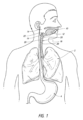
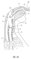
図1は、患者の口腔10、舌12、咽頭14を示す部分図であり、咽頭14は口腔10の背面の膜に囲まれた腔である。咽頭14は、食道16および気管18の開口部を含む。図示のように、食道16および気管18への開口部は、互いに隣接している。医療従事者が患者に挿管を試みるときに、従事者は、肺2に酸素を供給するために、挿管装置を気管18内に配置することを試みる。上述したように、従事者は挿管装置を食道16内に配置することを回避する必要があり、その際、声帯や体内の他の組織構造体に望ましくない外傷を与えないように、緩慢かつ慎重に進める必要がある。
1 is a partial view of a patient's
食道16の壁は、横紋筋および平滑筋で構成されている。食道16は蠕動運動によって食物を胃の方へ下降させるので、食道16の壁には構造的な補強体がなく、自然に柔軟である。一方、気管18は比較的丈夫で、気管支および肺2に空気を運ぶという機能を考えると、当然潰れないように構成されている。気管18の壁は、気管18が潰れるのを防ぐために、複数の軟骨の半円形のリング20を含む。気管20は食道16の前方にあり、食道16と気管の開口部とは喉頭蓋22という小さなフラップによって隔てられている。喉頭蓋22は、ヒトが食べ物などを飲み込むときに気管を保護する。
The wall of the
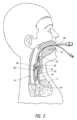
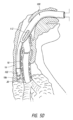
図2は、患者に挿管するために使用されるような従来の装置50を例示する。図示のように、装置50は、口および口腔から気管18に挿入される。従事者は、喉頭蓋22および声帯24を横断しながら、食道ではなく気管18に装置50を挿入する必要がある。特に声帯24を傷つけないよう、医療従事者は細心の注意を払う必要がある。一旦適切に配置されたら、従事者は任意で装置50上のバルーン52を膨らませて気管18内に装置をアンカー固定することができる。従事者が装置50の配置を確認した後に、患者の換気を行うことができる。
FIG. 2 illustrates a
現在、気道管理にはNellcor社製のコンビチューブ(Combitube)が一般的に使用されている。ダブルルーメン気道として周知のコンビチューブは、救急隊員の他、緊急救命室でも使用されるブラインド・インサーション・エアウェイ・デバイス(BIAD)である。コンビチューブは、カフ付きダブルルーメンチューブを用いて、呼吸困難患者の気管挿管を可能にすることを目的としている。ダブルルーメンチューブを患者の気道に挿入し、患者の肺を換気することができる。カフを膨らませることで、装置は気管内チューブと同様の機能を発揮し、通常は食道を閉鎖し、換気を行い、胃内容物の肺への吸引を防ぐことができる。 Currently, the Combitube, manufactured by Nellcor, is commonly used for airway management. The Combitube, commonly known as a double-lumen airway, is a blind insertion airway device (BIAD) used by paramedics and in emergency rooms. The Combitube is intended to allow for the intubation of patients with respiratory distress using a cuffed double-lumen tube. The double-lumen tube is inserted into the patient's airway and the patient's lungs can be ventilated. By inflating the cuff, the device functions similarly to an endotracheal tube, typically closing off the esophagus, providing ventilation, and preventing aspiration of gastric contents into the lungs.
しかしながら、従来の挿管装置の設置は、装置の配置が不適切になるリスクがあり、非常に困難である。装置の配置が不適切な場合、そのリスクを認識しないと致命的な事態になり得る。上述したような従来の装置では、そのような装置の配置について十分に訓練された人による配置が必要である。また、従来の装置を設置する際には、十分な訓練を受けている人でも慎重に進める必要がある。 However, installation of conventional intubation devices is extremely difficult due to the risk of improper device placement. Improper device placement can be fatal if the risks are not recognized. Conventional devices such as those described above require deployment by individuals who are fully trained in the deployment of such devices. Furthermore, even well-trained individuals must proceed with caution when installing conventional devices.
加えて、患者の人工呼吸を行う際の送気のタイミングを改善する必要がある。特に、この必要性は、患者が苦痛を感じており、酸素吸入と血液循環を再確立するための胸部圧迫との両者が必要な場合に生じる。現在、通常のCPRのように、ヒトの人工呼吸(例、支援換気や口移し)および胸部圧迫のタイミングを合わせないと、ヒトの通常の人工呼吸が圧迫の効果に反して作用し得る。例えば、大量の空気を繰り返し送り込む支援換気は、胸腔内の圧力を上昇させ、また、心臓にかかる圧力を上げることで抵抗を増加させ得る。この背圧により、心臓および両肺が血液で満たすことが阻害され得る。その結果、心臓および両肺を血液で満たす能力が阻害され、圧迫後に循環する血液量が少なくなるため、胸部圧迫の効果が低くなる。 In addition, there is a need to improve the timing of air delivery when ventilating a patient, especially when the patient is in distress and requires both oxygen inhalation and chest compressions to re-establish blood circulation. Currently, if human ventilation (e.g., assisted ventilation or mouth-to-mouth) and chest compressions are not timed, as in conventional CPR, conventional human ventilation can counter the effectiveness of compressions. For example, assisted ventilation, which repeatedly delivers large volumes of air, can increase intrathoracic pressure and also increase resistance by increasing pressure on the heart. This back pressure can inhibit the heart and lungs from filling with blood. As a result, the ability of the heart and lungs to fill with blood is inhibited, and less blood is circulated after compressions, making chest compressions less effective.
ヒトを効果的に換気することができるとともに従事者が必要とする最小限の訓練で効果的に配置することができる換気装置およびシステムのうちの少なくともいずれか一方に対するニーズが依然として存在する。加えて、ヒトの体内の酸素化血液を循環させるための胸部圧迫による支援換気の効果を最適化する、このような換気装置および方法に対するニーズもある。 There remains a need for ventilation devices and/or systems that can effectively ventilate a human and that can be effectively deployed by personnel with minimal training. Additionally, there is a need for such ventilation devices and methods that optimize the effectiveness of chest compression assisted ventilation to circulate oxygenated blood in the human body.
本開示は、自然な呼吸口を使ってヒトを処置するための方法およびシステムを含む。一例として、本開示は、ヒトにおける換気のためのシステム、および胸部圧迫の効率を高めるためのシステムを含む。一態様によるシステムは、ヒトの呼吸口内に挿入されるように構成され、ヒトの身体通路内に配置するための作業部を有する換気装置を備え、換気装置は、作業部に露出した圧力ルーメンを有し、圧力ルーメンは、圧力ルーメンを用いて身体通路内の圧力変化を検知するように構成されたセンサーと流体連通し、換気装置は、ヒトを換気するために作業部を通して空気のボーラスを供給するように構成された制御システムを有し、制御システムは、胸部圧迫の結果生じる身体通路内の圧力変化を検知すると、空気のボーラスの送達タイミングを変更し、胸部圧迫後にヒトの胸腔の再膨張を支援するのに十分な量の空気のボーラスを送達するように構成される。 The present disclosure includes methods and systems for treating a human using a natural breathing port. By way of example, the present disclosure includes a system for ventilation in a human, and a system for increasing the efficiency of chest compressions. A system according to one aspect includes a ventilator configured to be inserted into a breathing port of the human and having a working portion for placement in a body passageway of the human, the ventilator having a pressure lumen exposed to the working portion, the pressure lumen in fluid communication with a sensor configured to sense a pressure change in the body passageway with the pressure lumen, the ventilator having a control system configured to deliver a bolus of air through the working portion to ventilate the human, the control system configured to alter the timing of delivery of the bolus of air upon sensing a pressure change in the body passageway resulting from chest compressions, to deliver a bolus of air of a volume sufficient to assist re-expansion of the human's thoracic cavity after chest compressions.
本開示は、ヒトを人工的に換気するためのシステムをさらに含み、該システムは、ヒトの呼吸口内に挿入するように構成され、ヒトの身体通路内に配置するための作業端を有する換気装置であって、身体通路内の圧力変化を検知するように構成された圧力センサーを有する換気装置を備える。換気装置は、身体通路内の圧力変化が検知されるまで、予め定められた速度でヒトの気道に空気のボーラスを送達するように構成された制御システムを有し、その後、制御システムは、センサーが身体通路内の空気の圧力変化を検知するまで空気のボーラスの送達を遅らせることによって予め定められた速度を変更するように構成されており、身体通路内の圧力変化は胸部圧迫に起因している。システムはまた、圧縮後に胸腔を拡張することを支援するために、体積を増加させた空気のボーラスを供給することができる。エアボーラスの投入タイミングは、肺抵抗の増加と、エアボーラスの投入による胸部の反動を支援することとの両者で、胸部圧迫の効果を高めている。その結果、胸の反動が大きくなり、続く胸部圧迫の効果が高まり、血液の循環も良くなる。 The present disclosure further includes a system for artificially ventilating a human, the system comprising a ventilator configured for insertion into the respiratory opening of the human and having a working end for placement in a body passageway of the human, the ventilator having a pressure sensor configured to detect a pressure change in the body passageway. The ventilator has a control system configured to deliver a bolus of air to the airway of the human at a predetermined rate until a pressure change in the body passageway is detected, whereupon the control system is configured to modify the predetermined rate by delaying delivery of the bolus of air until the sensor detects a pressure change in the air in the body passageway, the pressure change in the body passageway being due to chest compression. The system can also deliver an increased volume bolus of air to assist in expanding the thoracic cavity after compression. The timing of the air bolus injection enhances the effectiveness of chest compressions by both increasing pulmonary resistance and by assisting in chest recoil from the injection of the air bolus. This results in greater chest recoil, which enhances the effectiveness of subsequent chest compressions and improves blood circulation.
本明細書に記載のシステムは、さらに、身体通路内の圧力変化をフィードバックするように構成された制御システムをさらに含み得る。 The systems described herein may further include a control system configured to provide feedback of pressure changes within the body passageway.
本明細書に記載のシステムは、胸腔内の空気の体積の変化を測定することにより、胸部圧迫の質に基づいてフィードバックを提供するように構成された制御システムをさらに備えることができる。一例として、フィードバックは、胸部圧迫の望ましい時間を識別するための指示信号を含む。別例は、作業部が第1のルーメンに流体連通する遠位側開口部および第2のルーメンに流体連通する中間開口部を含むシステムを備える。制御システムは、身体通路内の遠位側開口部を通して吸引を引き寄せ、吸引を一定時間維持するように構成される。制御システムは、身体通路が吸引によって遠位側開口部に対して引き寄せられるかどうかを判断し、身体通路が遠位側開口部に対して引き寄せられると判断できなかった後に第1のルーメンを通してヒトを換気し、身体通路が遠位側開口部に対して引き寄せられると判断した後に、第2のルーメンを通してヒトを換気し、第2のルーメンを通した換気中に吸引を維持するようにさらに構成されている。 The systems described herein may further include a control system configured to provide feedback based on the quality of chest compressions by measuring changes in the volume of air in the thoracic cavity. In one example, the feedback includes an instruction signal to identify a desired duration of chest compressions. Another example includes a system in which a working unit includes a distal opening in fluid communication with a first lumen and an intermediate opening in fluid communication with a second lumen. The control system is configured to draw suction through the distal opening in the body passageway and maintain the suction for a period of time. The control system is further configured to determine whether the body passageway is drawn against the distal opening by suction, ventilate the person through the first lumen after failing to determine that the body passageway is drawn against the distal opening, ventilate the person through the second lumen after determining that the body passageway is drawn against the distal opening, and maintain suction during ventilation through the second lumen.
別例では、システムは、作業部上に膨張式アンカーを含むことができる。膨張式アンカーは、換気装置の作業部に結合されたバルーンを備え得る。さらに、換気装置の近位部は、フェイスマスクをさらに備える。一実施例では、換気装置の近位部は、ヒトの口の中での換気装置の潰れを防止するための補強部をさらに備える。換気装置の近位部はまた、ヒトの換気パラメーターを調整するための圧力解放弁をさらに含むことができる。 In another example, the system can include an inflatable anchor on the working portion. The inflatable anchor can include a balloon coupled to the working portion of the ventilator. Additionally, the proximal portion of the ventilator further includes a face mask. In one embodiment, the proximal portion of the ventilator further includes a reinforcement portion to prevent collapse of the ventilator in the mouth of the person. The proximal portion of the ventilator can also further include a pressure relief valve to adjust ventilation parameters of the person.
また、本開示は、ヒトにおける換気のための方法、および胸部圧迫の効率を高める方法をさらに含む。例えば、そのような方法は、ヒトの呼吸口内に装置を挿入するステップであって、装置はヒトの身体通路内に配置するための作業部を有し、装置は作業部に露出した圧力ルーメンを有する、挿入ステップと、圧力ルーメンを使用して身体通路内の圧力変化を検知するステップと、作業部を通して空気のボーラスを送り、ヒトを換気するステップと、胸部圧迫の結果生じる身体通路内の圧力変化を検知したときに、空気のボーラスの供給タイミングを変更し、胸部圧迫の後に空気のボーラスを遅延して供給するステップと、遅延した空気のボーラスを、ヒトの胸腔の再膨張を支援するのに十分な量で供給して、その後の胸部圧迫の効果を高め、血液循環を増加するステップと、を含むことができる。 The present disclosure also includes methods for ventilation in a human and methods for enhancing the efficiency of chest compressions. For example, such methods may include inserting a device into a respiratory port of the human, the device having a working portion for placement in a body passageway of the human, the device having a pressure lumen exposed to the working portion; sensing a pressure change in the body passageway using the pressure lumen; delivering a bolus of air through the working portion to ventilate the human; modifying the timing of delivery of the bolus of air upon sensing a pressure change in the body passageway resulting from chest compressions to deliver a delayed bolus of air after the chest compressions; and delivering the delayed bolus of air in an amount sufficient to assist in re-expansion of the human's chest cavity to enhance the effectiveness of subsequent chest compressions and increase blood circulation.
この方法の別例では、作業部は、第1のルーメンに流体連通する遠位側開口部および第2のルーメンに流体連通する中間開口部を含み、この方法は、装置の遠位側開口部を通して吸引力を引き寄せ、一定期間吸引力を維持するステップと、身体通路からの組織が遠位側開口部をシールしない場合に第1のルーメンを通してヒトを換気するステップと、身体通路からの組織が遠位側開口部をシールする場合に遠位側開口部を通して吸引力を維持し第2のルーメンを通してヒトを換気するステップと、をさらに含む。 In another example of this method, the working section includes a distal opening in fluid communication with the first lumen and an intermediate opening in fluid communication with the second lumen, and the method further includes drawing suction through the distal opening of the device and maintaining the suction for a period of time, ventilating the person through the first lumen if tissue from the body passage does not seal the distal opening, and maintaining suction through the distal opening and ventilating the person through the second lumen if tissue from the body passage seals the distal opening.
この方法は、第1のルーメンを介した吸引の適用中に、最初に第2のルーメンを介して換気するステップをさらに含むことができる。 The method may further include initially ventilating through the second lumen while applying suction through the first lumen.
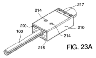
本明細書に開示される方法の別例は、ヒトの呼吸口への挿入に先だって装置を自動的に潤滑する方法を含み、該方法は、シャフトの遠位部に作業部を含む装置を提供するステップであって、作業部およびシャフトは、ヒトの身体通路内に配置されるように構成され、シャフトの近位部は、潤滑剤ハウジングを含む、挿入するステップと、潤滑剤ハウジングをシャフトに沿って遠位側に進めるステップであって、潤滑剤ハウジングの動きにより、シャフトを自動的に潤滑させる、潤滑剤ハウジングを進めるステップと、シャフトおよび作業部が潤滑されるように、シャフトおよび作業部から潤滑剤ハウジングを取り払うステップと、ヒトの身体通路内に装置の作業部を前進させることによって、作業部およびシャフトをヒトの自然呼吸口内に挿入するステップと、を含む。 Another example of the methods disclosed herein includes a method of automatically lubricating a device prior to insertion into a human breathing port, the method including the steps of: providing a device including a working portion on a distal portion of a shaft, the working portion and shaft configured to be placed in a body passage of the human, the proximal portion of the shaft including a lubricant housing; advancing the lubricant housing distally along the shaft, the movement of the lubricant housing automatically lubricating the shaft; advancing the lubricant housing; removing the lubricant housing from the shaft and working portion such that the shaft and working portion are lubricated; and inserting the working portion and shaft into the natural breathing port of the human by advancing the working portion of the device into the body passage of the human.
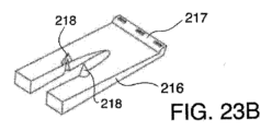
一態様による方法において、潤滑剤ハウジングを前進させるステップにより、潤滑剤ハウジング内の少なくとも1つの穿刺部材が潤滑剤供給部を穿刺する。追加の態様において、装置の作業部は、第1のルーメンに流体連通する遠位側開口部および第2のルーメンに流体連通する中間開口部をさらに備え、方法は、作業部を身体通路内で動かしながら遠位側開口部を通して吸引を引き寄せ、一定期間吸引を維持するステップと、身体通路が吸引により遠位側開口部に引き寄せられるかどうかを判断するステップと、身体通路が遠位側開口部に対して引き寄せられたと判断できなかった後に、第1のルーメンを通してヒトを換気するステップと、身体通路が遠位側開口部に対して引き寄せられたと判断した後に、第2のルーメンを通してヒトを換気し、第2のルーメンを通してヒトを換気している間に吸引を維持するステップと、をさらに含む。 In one aspect of the method, advancing the lubricant housing causes at least one piercing member in the lubricant housing to pierce the lubricant supply. In an additional aspect, the working portion of the device further comprises a distal opening in fluid communication with the first lumen and an intermediate opening in fluid communication with the second lumen, and the method further comprises drawing suction through the distal opening while moving the working portion through the body passageway and maintaining the suction for a period of time, determining whether the body passageway is drawn to the distal opening by the suction, ventilating the person through the first lumen after failing to determine that the body passageway is drawn against the distal opening, and ventilating the person through the second lumen after determining that the body passageway is drawn against the distal opening and maintaining the suction while ventilating the person through the second lumen.
本開示は、身体通路を介してヒトを換気するための装置をさらに含む。例えば、装置は、身体通路に挿入されるように構成された近位部および遠位部を有する管状部材と、管状部材の近位部に摺動可能に配置された潤滑剤ハウジングであって、管状部材に沿った潤滑剤ハウジングの移動により、潤滑剤ハウジングから管状部材に潤滑剤が塗布される、潤滑剤ハウジングと、を備えることができ、潤滑剤ハウジングは管状部材から取り払い可能である。 The present disclosure further includes an apparatus for ventilating a human through a body passageway. For example, the apparatus can include a tubular member having a proximal portion and a distal portion configured for insertion into the body passageway, and a lubricant housing slidably disposed in the proximal portion of the tubular member, where movement of the lubricant housing along the tubular member applies lubricant from the lubricant housing to the tubular member, the lubricant housing being removable from the tubular member.
別例では、装置は、潤滑剤ハウジングの動きにより、潤滑剤ハウジング内の少なくとも1つの穿刺部材が潤滑剤を含む潤滑剤供給部を穿刺するように構成されてもよい。装置の変形例は、潤滑剤ハウジングが、同潤滑剤ハウジングの内部に枢動可能に結合されたレバーアームを含み、少なくとも1つの穿刺部材がレバーアーム上に配置される態様を含む。 In another example, the device may be configured such that movement of the lubricant housing causes at least one piercing member within the lubricant housing to pierce a lubricant supply containing the lubricant. Variations of the device include an embodiment in which the lubricant housing includes a lever arm pivotally coupled to an interior of the lubricant housing, and the at least one piercing member is disposed on the lever arm.
本開示はまた、ヒトにおける心臓の収縮を判断する方法を含む。例えば、ヒトの気管や食道を用いて心臓の収縮を判断する方法などが挙げられる。例えば、そのような方法は、ヒトの自然な呼吸口内に換気装置の作業部を挿入するステップであって、換気装置が圧力センサーと流体連通している圧力検知ルーメンを含み、圧力検知ルーメンが作業部に沿って配置される、挿入するステップと、圧力検知ルーメンを身体通路内に配置するステップと、圧力検知ルーメンおよび圧力センサーを使用して身体通路の圧力の変化を監視するステップと、心臓の電気的活動を追跡して心臓の心電信号を測定するステップと、身体通路の圧力の変化と心臓の心電信号との関連性から心臓の収縮を判断するステップと、を含むことができる。 The present disclosure also includes a method for determining cardiac contractions in a human, such as using a human trachea or esophagus to determine cardiac contractions. For example, such a method may include inserting a working portion of a ventilator into a natural breathing orifice of a human, the ventilator including a pressure sensing lumen in fluid communication with a pressure sensor, the pressure sensing lumen being disposed along the working portion; disposing the pressure sensing lumen in a body passageway; monitoring pressure changes in the body passageway using the pressure sensing lumen and the pressure sensor; tracking cardiac electrical activity to measure an electrocardiogram signal of the heart; and determining cardiac contractions from a correlation between the pressure changes in the body passageway and the electrocardiogram signal of the heart.
本方法は、身体通路の圧力の変化を測定する際に信号を提供することをさらに含むことができる。信号が電子信号からなる場合、心臓モニタリング装置に電子的に送信される。これに代えて、または加えて、信号は、従事者が信号を電気的活動に関連付け、心臓の収縮を判断できるようにするための音声信号または視覚信号で構成することができる。 The method may further include providing a signal upon measuring the change in pressure in the body passageway. If the signal comprises an electronic signal, it is transmitted electronically to a cardiac monitoring device. Alternatively, or in addition, the signal may comprise an audio or visual signal to enable a practitioner to correlate the signal with electrical activity and determine cardiac contractions.
本開示は、吸引源および気体供給部を用いて1つ以上の身体通路を介してヒトを換気するための装置をさらに含む。例えば、装置は、少なくとも1つの第1のルーメンおよび第2のルーメンを有する管状部材であって、第1のルーメンは、管状部材の遠位部に向かって位置する第1の開口部に流体連通され、第2のルーメンは、管状部材の壁に沿って第1の開口部の近位側に位置する中間開口部に流体連通され、第1の開口部および中間開口部は管状部材内で流体隔離される、管状部材と、管状部材上に摺動可能に結合されたマスクと、マスクの近位側に位置する延長部であって、延長部は、ループ形状の大きさを調整することによってマスクから遠位側に延びる遠位部の長さを調整することができるように、ループ形状を有する、延長部と、気体供給部を第1のルーメンまたは第2のルーメンのいずれかを通して流体的に配向するように構成された弁を有する制御システムと、を備え、制御システムは、吸引源からの吸引を第1の開口部および第1のルーメンを通して配向し、吸引の結果としての第1の開口部のシールの形成を識別するように構成されており、制御システムは、第1の開口部のシールが識別されない場合には第1のルーメンを通してヒトを換気し、第1の開口部のシールが識別される場合には第1の開口部を介して吸気を維持しながら第2のルーメンを通してヒトを換気する。 The present disclosure further includes an apparatus for ventilating a human through one or more body passageways with a suction source and a gas supply. For example, the apparatus may include a tubular member having at least a first lumen and a second lumen, the first lumen being fluidly connected to a first opening located toward a distal portion of the tubular member, the second lumen being fluidly connected to an intermediate opening located along a wall of the tubular member proximal to the first opening, the first opening and the intermediate opening being fluidly isolated within the tubular member, a mask slidably coupled onto the tubular member, and an extension located proximal to the mask, the extension being configured to adjust the length of the distal portion extending distally from the mask by adjusting the size of the loop shape. , an extension having a loop shape; and a control system having a valve configured to fluidly direct the gas supply through either the first lumen or the second lumen, the control system being configured to direct suction from a suction source through the first opening and the first lumen and identify formation of a seal at the first opening as a result of the suction, the control system ventilating the person through the first lumen if a seal at the first opening is not identified, and ventilating the person through the second lumen while maintaining inspiration through the first opening if a seal at the first opening is identified.
本明細書に記載のシステムおよび方法は、呼吸気体中の二酸化炭素(CO2)の濃度または分圧を監視する装置(カプノグラフィー)と互換性がある。これらの装置は、主に麻酔時や集中治療時に使用するモニタリングツールであり、再呼吸システムを使用する際の呼気CO2のモニタリングが注目される。本明細書に記載された換気システムをこのようなカプノグラフィーシステムと一体的に設けることができるため、患者のケアを改善することができる。さらに、本明細書に記載されたシステムおよび方法は、酸素供給装置および/または電源装置などの緊急車両に見られる装置と互換性がある。いくつかの変形例では、本開示のシステムは、システムが訓練された緊急要員ではない最初の応答者によって使用され得るそれらの状況において適切な操作を確実にするために、音声または(表示画面の使用を通じて)映像による指示も提供することができる。 The systems and methods described herein are compatible with devices that monitor the concentration or partial pressure of carbon dioxide (CO 2 ) in respiratory gases (capnography). These devices are monitoring tools primarily used during anesthesia and intensive care, with a focus on monitoring exhaled CO 2 when using rebreathing systems. The ventilation systems described herein can be integrated with such capnography systems, thereby improving patient care. Additionally, the systems and methods described herein are compatible with devices found in emergency vehicles, such as oxygenators and/or power supplies. In some variations, the systems of the present disclosure can also provide audio or visual (through the use of a display screen) instructions to ensure proper operation in those situations where the system may be used by first responders who are not trained emergency personnel.
本発明は、添付の図面と合わせて読むと、以下の詳細な説明から最もよく理解される。一般的な慣行に従って、図面の様々な要素は実寸大ではないことを強調する。逆に、様々な要素の寸法は、分かりやすくするために、任意に拡大または縮小されている。また、明瞭化のために、本発明の特定の要素は、一部の図面には描かれていない場合がある。図面に含まれるのは、図面の簡単な説明に記載の図である。 The invention is best understood from the following detailed description when read in conjunction with the accompanying drawings. It is emphasized that, according to common practice, the various elements in the drawings are not drawn to scale. Conversely, the dimensions of the various elements have been arbitrarily increased or decreased for clarity. Also, for purposes of clarity, certain elements of the invention may not be depicted in some of the drawings. Included in the drawings are the figures described in the Brief Description of the Drawings.
本発明の装置、システムおよび方法を説明するに先だって、本発明は、説明された特定の治療用途および移植部位に限定されず、よって変化することを理解されたい。また、本明細書で使用される用語は、特定の実施形態を説明するためのものであり、本発明の範囲は添付の特許請求の範囲によってのみ限定されるので、限定することを意図するものではないことを理解されたい。 Before describing the devices, systems, and methods of the present invention, it is to be understood that the invention is not limited to the particular therapeutic applications and implantation sites described, as such may vary. It is also to be understood that the terminology used herein is for the purpose of describing particular embodiments, and is not intended to be limiting, as the scope of the present invention will be limited only by the appended claims.
特に定義されていない限り、本明細書で使用されているすべての技術用語および科学用語は、本発明が属する技術分野の当業者によって一般的に理解されているのと同じ意味を有する。「近位側」、「遠位側」、「近傍」、「遠方」という用語は、ユーザーに対する位置または箇所を示し、「近位側」はユーザーに近い位置または箇所、「遠位側」はユーザーから遠い位置または箇所を意味する。 Unless otherwise defined, all technical and scientific terms used herein have the same meaning as commonly understood by one of ordinary skill in the art to which this invention belongs. The terms "proximal," "distal," "near," and "far" refer to a location or location relative to the user, with "proximal" meaning a location or location closer to the user and "distal" meaning a location or location farther from the user.
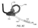
図3Aは、本開示による改善されたシステムの一例の様々な構成要素を示す図である。図示のように、換気装置100は、患者の体内に挿入される作業端102を含んでいる。作業端は、第1のルーメン(図示しない)を含む遠位側チューブ104を含むことができ、第1のルーメンは換気装置100の遠位側開口部106を通って延び、1つ以上の近位側チューブ118を介して制御ユニット(人工呼吸器とも呼ぶ)150および供給源160のうちの少なくともいずれか一方に流体連通している。制御ユニット150には、吸引を行うように構成された装置の他、回収キャニスターを含めることもできる。動作中、制御ユニット150は、第1の流体経路122を通じて吸引を指示するか真空を適用し、これにより遠位側開口部106で吸引または負圧が生じる。源160は、酸素、空気、または肺への送達の換気に望まれる任意の他の気体から構成することができる。源160は、制御装置150の物理構造体内に入れ子に構成することが可能である。しかしながら、源160は任意であり、制御装置は周囲の空気のみを使用して患者を換気することができる。
3A is a diagram illustrating various components of an example of an improved system according to the present disclosure. As shown, the
制御ユニット150は、装置100を設定時間この状態に保持し、第1のルーメン内の圧力または流量パラメーターを監視して、第1または第2のどちらを通して換気するかを判定する。図3Aに示す例は、装置の適切な機能を支援する1つ以上の機能を備えたハブ108をさらに含む。以下、その特徴について詳しく説明する。さらに、遠位側開口部106は、ポートが第1のルーメンと流体経路をなしている限り、装置の遠位端に任意の数のポートを含むことができる。同様に、中間開口部112は、それらの開口部が第2のルーメンと流体連通している限り、任意の数の開口部で構成することができる。加えて、装置の変形例は、口ではなく、鼻から挿入するタイプであってもよい。
The
換気装置100は、装置100から中間開口部112で出る第2のルーメン(図示しない)を収容する近位側チューブ110をさらに備える。後述するように、遠位側開口部および第1のルーメンは、装置の作業端102を介して中間開口部および第2のルーメンから制御ユニット150に至るまで流体的に隔離される。この流体隔離により、制御ユニット150は、どのルーメンを使って患者の換気を行うかを決定することができる。制御ユニットは、装置が気管18ではなく食道16に配置されている場合に、第2のルーメンおよび中間開口部112に流体連通する第2の流体経路124を通して流れを誘導する。
The
図3Aに例示する換気システム100は、任意の換気口116を備えた任意のマスク114も示している。本システムの変形例として、マスクなし、またはマウスガードや任意のその他の一般的に使用される装着器具などの他のそのような器具を使用した代替構成を含むことができる。後述するように、マスク114や他の装着器具を使用することで、従事者が患者に挿入する際に装置100の方向を適切に配向することを支援することができる。装置の変形例は、吸入中に気体が肺に確実に導かれるように、装置の近位側領域を患者に固定するバルーン、スポンジまたは任意の他の構造体を含むことができる。マスク(または本明細書に記載の他の構造体)は、マスクを患者の所定位置に固定するための固定バンド、テープ片、または一時的な接着剤を含むことができる。マスクなどを使用して、作業端102を患者の体内にどの程度進めるかを決定することができる。これに代えて、または組み合わせて、装置100は、従事者が装置を患者の体内に適切に進めることを支援するために、目盛りマーク134を含むことができる。マスクは摺動自在であり、マスクから遠位側または近位側の開口部までの長さを調整することができる。
3A also shows an
図3Aはまた、様々な装置動作シーケンス、手動制御、または装置制御停止を可能にする複数の制御部152を備える制御システム150を示す代表図である。例えば、システム150は、従事者が患者の吸気および呼気を手動で調整できるように、手動換気制御部を含むことができる。制御部152は、心肺蘇生を行うためのリセットモードまたは急速換気モードを含むことができる。制御部152は、連続気流モードまたは連続真空モードを備えており、身体の通路に溜まったゴミや体液の除去を支援する。また、従事者が気管内挿管を行う場合には、制御部により従事者は装置100を気管内チューブに直接接続することも可能である。追加の別例として、システムにより、換気効率を高めるために、活性ルーメンを通して一定期間送風し、その後一定期間吸引することからなる能動的換気が可能である。いくつかの変形例では、システムは、従事者が開口部を気管に合わせることができるように、チューブの他の開口部と同様に、換気口がマスクに対して回転しないように構成されている。
3A is also a representative diagram of a
図3Aに示す装置は、作業端に配置された1つ以上の電極をさらに含むことができる。例えば、ハブ108が電極となり、心臓に電気を流すことで、患者の不整脈を除細動したり、心拍数や収縮力を増加させたりすることができる。加えて、1つ以上の電極を、患者の口、食道、または気管に挿入するように構成されたチューブに挿入または埋め込むことができる。現在、患者の胸部上にパッドを貼り付けて使用しているが、これに比べて上記配置により操作者はより直接心臓を電気的に刺激できるようになるため、有利である。食道にチューブを入れると、大動脈が食道と平行に延びているため、脈拍をより検知しやすくなる。これにより、救助者が患者に触れることなく、脈拍を測定することができるようになる。また、たまたま居合わせた人が患者の脈拍を確認する訓練を受けていない可能性がある場合、訓練を受けていない居合わせた人は、CPRを行うことができるようになる。加えて、患者の口腔内に挿入されたチューブが動脈を圧迫する可能性がある場合、後述する圧力センサーをチューブ上に設置することで、圧力の変化があればこれを検知することができる。
3A may further include one or more electrodes disposed at the working end. For example, the
さらなる変形例において、制御システム150は、個別の独立した箱型の構成ではなく、装置本体102の1つ以上の部分に一体的に形成可能である。加えて、換気システム100は、除細動器と連動するように任意に構成することができる。システム100の別例として、従事者が胸部圧迫を行うべきタイミングを示すために、聴覚、視覚、あるいは触覚の感覚を提供するように構成することも可能である。代替の変形例では、制御システム150は、バッグバルブマスク(BVM)で使用されるものなどの換気バッグを含むことができる。この構成により、バッグの圧縮および反動を利用して、換気および吸引の両者を行う完全な使い捨てシステムが実現される。このバッグを心肺蘇生時に患者の胸部に装着することで、胸部圧迫と換気とのタイミングを合わせることができる。装置の遠位側チューブは、制御システムを使用して気管および食道の両者にてなお作動し、その位置を自動的に決定し、どちらの位置でも肺を胃から効果的に隔離することができる。
In a further variation, the
図3Aはまた、装置100の描かれた変形例を、作業端に位置する任意のバルーン132や他の拡張可能部材を有するものとして示している。使用時、バルーンは遠位側開口部106に隣接する装置に沿ったいかなる箇所にでも配置することができる。これに代えて、あるいは組み合わせて、バルーンを中間開口部に隣接して配置してもよい。
FIG. 3A also illustrates an depicted variation of the
装置100を形成する様々なチューブは、装置が上部呼吸器系を通過できるように十分に可撓性を備えるべきである。これに代えて、またはこれに加えて、チューブの一部を患者の口や歯で潰されるのに耐久するような構造にすることも可能である。さらなる変形例において、システム100は、遠位側開口部106の、中間開口部112およびマスク114のうちの少なくともいずれか一方に対する距離を調整可能で(あるいは段階部134に対して移動可能でも)あるように構成することができる。同様の変形例は、遠位側開口部106、マスク114、または段階部134に対して調整可能に配置できる中間開口部112を含む。
The various tubes forming the
図3Bおよび図3Cは、マスク114がチューブ110の長さに沿って調整可能な装置100の追加の一態様を示す図である。これにより、遠位側チューブ110の長さを調整することができ、様々な患者の体格に対応することができる。また、図示の変形例では、調整可能なループを形成するマスク近傍の気道チューブ110および延長チューブ118が示されている。場合によっては、スライド式マスク114でチューブの長さを調整することで、小柄な患者のためにマスクから気道チューブが近位側に延びるときに、テコの原理でアームが形成される。気道チューブ110の材質は、通常延長チューブ118の材質ほど可撓性を備えるものではない。その場合、マスクから外に延びる気道チューブに横からの圧力が加わると、気道が大きく動いたり、ねじれたりすることがある。調整可能ループは、気道チューブおよび延長チューブの両者を含む。このループは、チューブをマスクの方向に巻き戻すことで、マスク/遠位側チューブにかかるはずの機械的なてこの作用を低減する。図3Bは、マスク114から気道チューブ110の短い長さが延びる(例えば、マスク114がチューブの遠位端に向かって進められる)、より小柄なヒトに用いられる構造体を例示する。これにより、マスク114の近位側のループのサイズが大きくなり、マスクの近位側のチューブによってかかるはずの機械的なてこの作用が低減される。図3Cは、気道チューブ110がマスク114から延長され、マスク114の近位側のループのサイズを低減している態様を示す図である。
3B and 3C show an additional embodiment of the
図3Bおよび図3Cは、複数の中間開口部112を有し、遠位側開口部106がチューブの端を通って延びている一態様による装置をさらに示す図である。加えて、延長チューブ/近位側チューブ118は、後述するように、遠位側開口部および中間開口部に結合される第1のルーメンおよび第2のルーメンを収容するためのマルチルーメン構造体を含む1本のマルチルーメンチューブから構成される。
3B and 3C further illustrate one embodiment of the device having multiple
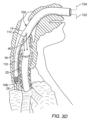
換気装置の使用には、前部開口部/中間開口部112が気管の開口部を喉頭に合わせるように、マスクから延びるチューブ110の長さを適切にサイズ調整する必要がある。これは通常チューブの長さに沿ってマスクを摺動させることでチューブの長さを調整し、挿入深さを決定することで行われる。図3Dに示すように、装置の変形例は、装置100の遠位端の円周にわたって延びる複数の遠位側開口部106を含むことができる。挿入中、チューブ110は、開口部106から吸引しながら、咽頭口部を通して進められる。遠位端が食道に入ると、食道が潰れて遠位側開口部106がシールされる。これにより、すべての患者でチューブ110が同じ解剖学的組織位置に配置される。遠位端が食道内の適切な深さまで移動してから完全にシールできるように、チューブ110に追加の中間開口部112(図3Bおよび図3Cに示すような)を追加することができる。一旦遠位端が潰れた食道内に適切に配置されると、マスクを摺動させて患者の顔に装着したり、バルーンを膨らませて上気道をシールしたりすることができる。
Use of the ventilation device requires proper sizing of the length of the
図3Eは、従来の換気チューブ172の配置を支援するための上述の要素の使用を示す図である。この変形例では、ガイド装置166は、遠位端に複数の吸引開口部168を含む。上述したように、ガイド装置166は、食道が開口部168を中心に潰れるように吸引をかけながら食道内に前進することができる。これにより、ガイド装置166の位置を積極的に判断することができる。ガイド装置166は、換気チューブ172を含むことができ、または換気チューブ172は、適切に配置されたときにガイド装置166のトラック170に沿って前進させることができる。いくつかの変形例では、遠位側開口部168におけるシールの生成は、気管内チューブを解放させることもできる。装置166が気管に挿入される場合、装置の位置は、(マーキングまたは他の測定値により)挿入深さと同様に、シール形成の欠如によって決定することができる。
3E illustrates the use of the above elements to aid in the placement of a
図4A乃至4Dは、本明細書に記載される換気装置100の気道ユニットまたは作業端102を示す部分図である。
Figures 4A-4D are partial views showing the airway unit or working
図4Aは、遠位側開口部106に流体連通している第1のルーメン128、および中間開口部112に流体連通している第2のルーメン130を示し、第1のルーメン128および第2のルーメン130が上述したように互いに流体隔離されている態様を示す図である。図4Aは、遠位側開口部106と中間開口部112との間の間隙126が、意図する患者に基づいて選択可能であることも示している。例えば、遠位側開口部106が食道または気管に位置するとき、中間開口部112は咽頭内またはその周辺に位置することが意図されているので、間隙126は平均体型のヒト用に選択することが可能である。ほとんどの場合、換気装置100の作業端102は、一回限りの使い捨て部品から構成される。したがって、換気装置100は、中間開口部112と遠位側開口部106との間に異なる間隙126を有する複数の使い捨て要素を含むことができる。例えば、乳幼児や小児、様々な体格のヒトに対応できるように、間隙を変えている。
4A shows a
図4Bは、図4Aの換気装置の作業端102を示す部分断面図である。一旦装置が患者の体内に適切に配置されると、制御ユニット150は、矢印30で示すように、第1の流路122から第1のルーメン128を通して吸引または真空をかけ、最終的に遠位側開口部106で真空状態を発生させる。追加の変形例として、操作者または従事者は、第1のルーメン128を通して空気を送ることによって、または遠位側開口部の吸引を使用して粒子または他の体液を除去しようと試みることによって、患者から食物または他の破片を取り除くことを選択することができる。システム150は、第1のルーメン130を通して真空引きを一定時間継続する。装置100が気管内に適切に配置されていれば(後述)、システム150は第1のルーメン128を通して換気を開始する。すなわち、システム100は、患者の肺を適切に換気するために、酸素やその他の気体を供給源160から循環するように供給し、患者から二酸化炭素を除去し始める。この状況においては、第2のルーメン130および中間開口部112を通る流れは必要ない。図4Bでは、第1のルーメン128が第2のルーメン130内に配置されているが、任意の数の変形例を使用することが可能である。例えば、ルーメンは同心円状であったり、平行状であったりする。さらなる変形例は、ルーメンを流体連通させることも可能であり、ここで、1つ以上の弁により、遠位側開口部からの換気か、中間開口部からの換気かを決定する。装置の配置が変わらないことを確認するために、装置は任意の数の安全チェックを含めることができる。例えば、一旦装置が気管に設置されたことを確認したら、装置は予め定められた間隔で気管に設置されていることを確認するチェックを再度行うことができる。これに代えて、装置はこのチェックをスライディングスケール(例えば、30秒で第1のチェック、2分で第2のチェック、10分で第3のチェックなど)でも行うことが可能である。さらなる一態様において、システムは、吸引フィルターが目詰まりして位置を誤認していないか、安全確認を行うように構成される。この場合、装置は真空を検知すると、遠位側ポートから換気を行う。この換気ボーラスは小さくても大きくてもよい。真空を監視し、遠位側のエアボーラス中に真空が失われたと判断した場合に、装置は食道でシールされたことを認識し、遠位側の吸引および近位側のポートからの換気を再開する。遠位側エアボーラス中に真空が失われない場合に、装置はフィルターが詰まっていると考えることができ、エラー信号が操作者に装置の作業端を交換するか、または障害物がないかを確認するように指示する。
4B is a partial cross-sectional view of the working
システム150は、換気し、吸引または真空を発生させる機構で構成することができる。一般的に、システム150は再利用可能である(一般的に使い捨てである作業端とは対照的に)。システム150は携帯可能であり、救急車などの緊急車両に貼り付けたり、台車や室内に組み込んだりすることができる。電池式装置、空気圧式装置、電源(ACコンセントなど)を必要とする装置など、さまざまな変形例がある。
The
図4Cは、遠位側開口部106が食道内に位置する状況を示す図である。この状況において、制御ユニット150は、第2のルーメン130を通して換気を行うように指示する。矢印32で示すように、中間ルーメン112は第2のルーメン130と流体連通しているため、中間開口部112で換気32が行われる。
Figure 4C illustrates a situation where the
図4Dは、装置が複数の中間開口部232、234、236、および238を含む、作業端102の別の態様を示す図である。声門上部の適切な深さのサイズ調整により、換気を送達するルーメン(例えば、上述したルーメン128)が喉頭の開口部に確実に整列する。図示の変形例は、大きなサイズ公差の中で適切に換気するために、深さのサイズ調整に関連する誤差のマージンを増加させる声門上換気ルーメンを示している。
FIG. 4D illustrates another variation of the working
換気ルーメンの開口部が組織で覆われている間に、換気した空気を喉頭、すなわち肺に配向することができることが重要である。図4Dでは、換気の大部分は、最後尾のポート232に配向される。このポート232が覆われたり塞がれたりすると、続いて次の開口部234に換気が導かれる。これは、喉頭のもっとも近傍の穴が確実に換気を受けるように、4つの開口部すべてに継続される。使用時、システムは、上述した近位側換気ポート232乃至238から流体的に分離している遠位側開口部106に負圧をかける。ポート232乃至238の全てが不用意に喉頭の遠位側に配置された場合、システムは近位側の換気ルーメン(例えば、128)内の負圧を検知し、気道装置の挿入が深すぎた(遠位側)ことを医療従事者に警告するトリガーとなる。システムは続いて従事者に気道装置のサイズ変更を指示することができる。
It is important to be able to direct ventilated air to the larynx, i.e., the lungs, while the ventilation lumen openings are covered with tissue. In FIG. 4D, the majority of ventilation is directed to the
図5A乃至5Eは、本明細書に記載の換気装置100を用いて患者を換気するプロセスを表す図である。
Figures 5A-5E are diagrams illustrating the process of ventilating a patient using the
図5Aは、従事者が換気装置100を口腔10内に、舌12を越えて咽頭14に進入させている態様を例示している。従事者は、施術中いつでも手動で装置を操作して、体内の液体や食べかすなどを吸引することができる。本明細書で説明するように、従事者は、作業端102を患者の体内に「盲目的に」進めることができる。その結果、作業端102は患者の食道16または気管18に到達することになる。
FIG. 5A illustrates an example of a practitioner advancing the
図5Bは、従事者が作業端102をヒトの気管18に進める状況を示す図である。一旦従事者が装置100を配置すると、従事者は制御ユニット150を起動し、装置100の配置を決定する処理を開始させることができる。これに代えて、装置上に搭載された1つ以上のセンサーは、自動的に制御ユニットの活性化をトリガーすることも可能である。いずれの場合も、制御ユニットは遠位側開口部106を通して真空を予め定められた時間引く。真空により圧力が低減され、遠位側開口部106内の空気が吸引される。制御ユニット150は、続いて真空、気流、または身体通路の壁、この場合は気管18が潰れて真空シールを形成したかどうかを示す任意の他の流体パラメーターを監視することにより、装置の状態を評価する。図5Bのように、装置が気管内に位置する場合に、吸引30は気管18の壁にほとんど影響を及ぼさないであろう。上述したように、気管18の壁は軟骨20の輪で補強されており、気道の構造的な剛性を高めている。制御装置150は遠位側開口部106(または第1のルーメン内)における真空シールの形成を検知しないため、システムは遠位側開口部106が(食道16ではなく)気管18に適切に配置されたと記録し、予め定められた時間(例えば、10乃至15秒)の後に、制御装置150は、真空引きを停止し、気体供給部160からの気体の供給と二酸化炭素の除去とを交互に行うことで患者の肺の換気を開始する。その結果、第1のルーメンは換気用ルーメンとして使用される。制御装置150が、流体や破片の吸引による真空や流量の変化を区別することが重要である。装置のいくつかの変形例では、制御装置150は、装置が吸引した流体または物質ではなく、真空シールの形成に至る十分な程度まで真空が構築または流量が低下したときにシールの形成を識別するように構成される。
FIG. 5B illustrates the practitioner advancing the working
制御ユニット150は、吸引のために主ルーメン内を負圧にする吸引モーター(または真空を発生させるベンチュリー装置などの類似装置)の歪みを測定することにより、シールが形成されているかどうかを判定することができる。制御ユニット150は、予め定められた時間後に吸引モーターへの歪みがゼロまたは最小であることを確認した場合、制御ユニット150は第1のルーメンを換気ルーメンとして使用する。
The
図5Dは、従事者が換気装置100の作業端102を気管18ではなく食道16に進ませた状態を示す図である。上記の図5Bによって描かれた状態と同様に、一旦従事者が装置100を配置すると、従事者は制御ユニット150を起動して、装置100の配置の決定処理を開始させることができる。上述したように、装置およびシステムの追加の変形例は、制御ユニットの活性化を自動的にトリガーすることができる1つ以上のセンサーを含むことができる。
FIG. 5D illustrates the practitioner advancing the working
図5Dは、制御ユニット150が遠位側開口部106を介して真空引きを所定時間行った状態を示す図である。真空により圧力が低減され、遠位側開口部106内の空気が吸引される。制御ユニット150は、真空、気流、または身体通路、この場合は食道16の壁が潰れたかどうかを示す任意のその他の流体パラメーターを監視することによって、続いて装置の状態を評価する。図示のように、壁が部分的または全体的に潰れ、遠位側開口部16に真空シールが形成される。上述した通り、筋肉は食道16の壁を形成する。気管18の軟骨リングとは対照的に、食道には補強構造体が無い。制御ユニットは、真空シールの形成を監視するように構成することができ、シールが所定期間残っている場合、制御ユニット150は、図5Eに描かれているように、中間開口部112への換気40を内外に配向する。図示し、上述したように、遠位側開口部106と中間開口部112との間隙は、中間開口部が咽頭14の中または近傍に留まるように選択することが可能である。しかしながら、この装置の変形例では、開口部112が患者の換気を継続できる限り、中間開口部が食道16に入ることを許容している。
FIG. 5D illustrates the
制御ユニット150は遠位側開口部106(または第1のルーメン内)における真空シールの形成を検知しないため、システムは遠位側開口部106が(食道16ではなく)気管18に適切に配置されたと記録し、予め定められた時間の後に、制御ユニット150は、真空引きを停止し、気体供給部160からの気体の供給と二酸化炭素の除去とを交互に行うことで患者の肺の換気を開始する。この状況において、装置は第2のルーメンを換気ルーメンとして使用する。食道16内に装置100の作業端102を配置することの付加的な利点として、真空シールが装置を定位置に維持するアンカー効果をもたらすことが挙げられる。この機能により、患者の頭部、首部、顔面の周囲にマスクなどの要素を固定する必要がなくなる。加えて、シールが形成された状態で、従事者が不注意に装置100を引っ張ると、真空シールが単純に破壊され、装置が食道16から離脱する。そのため、拡張式バルーンを引っ張ると気道や声帯などの組織構造体に外傷を生じさせる可能性のある、バルーンに左右される従来の人工呼吸器と比べ、安全性が高められる。
Because the
ある種の変形例では、装置100は一定時間後に換気を停止し、遠位側開口部を通して吸引を発生させる。このようなステップは、作業端が移動したり、位置が変わったりした場合の安全対策として考えられている。
In some variations, the
別例では、本明細書に記載される換気装置100のいずれかを、遠位側開口部を通して真空を提供しながら口腔内に前進させることができる。これにより、一旦装置が食道に入ると食道は遠位側開口部に対して潰れるため、装置のサイズを自動的に調整することができる。
In another example, any of the
図6A乃至6Cは、本明細書で説明する換気装置の作業端102の変形例を示す図である。図6Aは、外形を有する表面で包囲された開口部106を有するハブを示す図である。外形を有する表面により、遠位側開口部106が食べかすや他の流体で詰まる可能性を低減することが支援される。この要素により、食道の壁とシールを形成された開口部106を、(食べかすや体液等で)塞がれた開口部106と制御ユニットが誤認する事態を低減することも支援される。図6Bおよび図6Cは、換気装置の作業端102の追加の変形例を示す図である。これらの変形例では、作業端102は、ハブ付きでもハブ無しでも形成可能である。図6Bは、複数の開口部106を有する直線的なチューブを示す図である。図6Cは、開口部106を有する斜めに形成された端部を示す図である。
6A-6C are diagrams illustrating variations of the working
上述したように、本明細書に記載された装置は、圧縮した気体および弁を用いて空気圧で駆動することも、電気的に制御することも可能である。図7は、吸引モーター、空気圧縮機、および回路を使用して、第1の流体経路122(最終的に遠位側開口部に流体連通する)と第2の流体経路124(最終的に中間開口部に流体連通する)との間で切り換える電気駆動装置を示す概略図である。 As mentioned above, the devices described herein can be pneumatically driven using compressed gas and valves, or can be electrically controlled. Figure 7 is a schematic diagram showing an electrically driven device that uses a suction motor, air compressor, and circuitry to switch between a first fluid path 122 (which ultimately fluidly communicates with the distal opening) and a second fluid path 124 (which ultimately fluidly communicates with the intermediate opening).
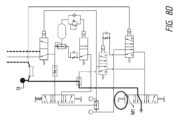
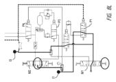
図8Aは、空気圧で駆動される本明細書に記載のシステムの構成要素を示す概略図の一例を示す図である。図8Bは、図8Aに見られる構成要素の一覧を示す表である。弁は上述した条件により、複数の状態で作動する。以下の説明は、図8Aの構成要素を示す概略図に見られる構成要素の異なる状態の一例を示すものである。 Figure 8A is an example of a schematic diagram showing components of a system described herein that are pneumatically actuated. Figure 8B is a table listing the components found in Figure 8A. The valve operates in multiple states depending on the conditions described above. The following description provides an example of the different states of the components found in the schematic diagram of Figure 8A.
中間供給弁P1(4/2);
状態1(公称、スプリングリターン):遠位側供給弁P2を通した真空供給の15秒タイミングを制御;
状態2(活性化):中間換気のための供給;
パイロット活性化:10水銀柱インチ(約33.8639kPa)真空
Intermediate supply valve P1(4/2);
State 1 (nominal, spring return): controls 15 second timing of vacuum supply through distal supply valve P2;
State 2 (active): Supply for intermediate ventilation;
Pilot activation: 10 inches of mercury vacuum
遠位側供給弁P2(4/2)状態1(公称、スプリングリターン):真空発生装置に電源を供給する;
状態2(活性化):遠位側換気のための電源を供給する;
パイロット活性化:中間供給弁の流量制御出力から40psi(約275.79kPa)、状態1。
Distal supply valve P2(4/2) state 1 (nominal, spring return): supplies power to the vacuum generator;
State 2 (Active): Provides power for distal ventilation;
Pilot activated: 40 psi from mid-supply valve flow control output, state 1.
パルス弁P3(3/2常開);
状態1(公称、スプリングリターン):インライン解放弁で設定圧力に達するまで、流量制御された速度でアキュムレーターの容量を満たす;
状態2:(活性化):アキュムレーターの容量を急速排気して、換気切換弁に送る;
パイロット活性化:インライン解放弁の出力より5psi(約34.47kPa)
Pulse valve P3 (3/2 normally open);
State 1 (nominal, spring return): Fills the accumulator to capacity at a flow-controlled rate until a set pressure is reached with an in-line relief valve;
State 2: (Activated): Rapidly exhaust the volume of the accumulator to the ventilation diverter valve;
Pilot activation: 5 psi from the output of the in-line relief valve
換気切換弁P4(3/2フルポート);
状態1(公称、スプリングリターン):パルス弁の出力を中間換気出力に配路;
状態2:(活性化):パルス弁の出力を遠位側換気出力に配路;
パイロット活性化:遠位側供給弁の出力から40psi(約275.79kPa)、状態2
Ventilation switching valve P4 (3/2 full port);
State 1 (nominal, spring return): Route the pulse valve output to the intermediate ventilation output;
State 2: (Activated): Route the pulse valve output to the distal ventilation output;
Pilot activated: 40 psi from distal supply valve output, state 2
作動弁M1(手動トグル、3位置、すべて戻り止め);
状態1(トグル・ダウン、「ON」):中間供給弁および遠位側供給弁に電源を供給;
状態2(トグル中央、「OFF/リセット」):供給を遮断し、システムを換気;
状態3(トグル・アップ、「真空」):すべての弁をバイパスし、真空生成器に供給。
Actuated valve M1 (manual toggle, 3 positions, all detents);
State 1 (toggle down, "ON"): Powers the middle and distal supply valves;
State 2 (toggle center, "OFF/Reset"): Shut off supply and ventilate system;
State 3 (toggle up, "vacuum"): Bypasses all valves and feeds the vacuum generator.
モード弁M2(手動トグル、3位置、戻り止め/戻り止め/瞬間の);
状態1(トグルダウン、戻り止め、「換気」):パルス弁および換気切換弁に電源を供給;
状態2(トグル中央、戻り止め、「バイパス」):パルス弁および換気切換弁への供給を遮断。
状態3(トグルアップ、瞬間のスプリングリターン、「オンデマンド」):パルス弁の供給を遮断し、換気切換弁に連続的に流量制御された供給
Mode Valve M2 (manual toggle, 3 position, detent/detent/momentary);
State 1 (toggle down, detent, "ventilation"): Powers the pulse valve and the ventilation selector valve;
State 2 (toggle center, detent, "bypass"): Cuts off supply to pulse valve and ventilation selector valve.
State 3 (toggle up, instantaneous spring return, "on demand"): Cuts off the pulse valve supply and provides continuous flow controlled supply to the ventilation diverter valve.
図8Aの構成要素概略図によって示されるシステムは、様々な作動モードを有することができる。一例では、図8Cに示すように、システムは、様々な弁の位置および中間供給弁の作動状態によって制御される8つの個別の作動モードを含むことができる。 The system illustrated by the component schematic of FIG. 8A can have various modes of operation. In one example, as shown in FIG. 8C, the system can include eight separate modes of operation controlled by the positions of the various valves and the actuation state of the intermediate supply valve.
モード0では、システムがOFFの状態に設定される。
M1をOFFに設定;
主電源が遮断;システムが換気;
In mode 0, the system is set to the OFF state.
Set M1 to OFF;
Mains power cut; system ventilated;
図8Dはモード1を示しており、システムを通して連続的に真空が適用されている。
M1を真空に設定
換気システムバイパス;真空出力での真空;真空インジケーターをON
FIG. 8D shows Mode 1, where a continuous vacuum is applied through the system.
Set M1 to vacuum Ventilation system bypass; Vacuum on vacuum output; Vacuum indicator ON
図8Eは、システムが配置検知に関与するモード2を示す;
M1をONに設定;
P2パイロット活性化まで(15秒)真空出力で真空にする;真空インジケーターをON;
FIG. 8E shows mode 2 in which the system participates in placement sensing;
Set M1 to ON;
Apply vacuum with vacuum output until P2 pilot activation (15 seconds); turn vacuum indicator ON;
モード3では、システムは遠位側開口部を通した換気に関与する。
M1をONに設定;M2を換気に設定;
真空が検知されない;P2パイロットが活性化;P4パイロットが活性化。
In mode 3, the system engages ventilation through the distal opening.
Set M1 to ON; Set M2 to Ventilation;
No vacuum detected; P2 pilot active; P4 pilot active.
図8Fはモード3Aを示しており、アキュムレーターはインライン安全弁が活性化する(30psi(約206.84kPa))まで制御された速度(0.67秒)で充填される;
遠位側換気インジケーターON。
FIG. 8F shows Mode 3A, in which the accumulator is charged at a controlled rate (0.67 seconds) until the in-line relief valve activates (30 psi);
Distal ventilation indicator ON.
図8Gはモード3Bを示している:P3パイロットが活性化し、P3を閉じ、アキュムレーター容量を急速排気によりP4へ排気;遠位側換気インジケーターON。 Figure 8G shows Mode 3B: P3 pilot activated, P3 closed, accumulator volume rapidly vented to P4; distal ventilation indicator ON.
モード4ー中間換気
M1をONに設定;M2を換気に設定
真空を検知;P1パイロット活性化;真空出力で真空。
Mode 4 - Intermediate ventilation Set M1 to ON; M2 to ventilation. Vacuum detected; P1 pilot activated; Vacuum on vacuum output.
図8Hはモード4Aを示しており、アキュムレーターはインライン安全弁が活性化する(30psi(約206.84kPa))まで制御された速度(0.67秒)で充填される;
真空インジケーターON;
中間換気インジケーターON。
FIG. 8H shows Mode 4A, in which the accumulator is charged at a controlled rate (0.67 seconds) until the in-line relief valve activates (30 psi);
Vacuum indicator ON;
Intermediate ventilation indicator ON.
図8Iはモード4Bを示す;P3パイロットが活性化し、P3が閉じ、アキュムレーターの容量を急速排気によりP4に排気;
真空インジケーターON;中間換気インジケーターON。
FIG. 8I shows Mode 4B; P3 pilot is activated, P3 is closed, and accumulator volume is vented to P4 via rapid exhaust;
Vacuum indicator ON; intermediate ventilation indicator ON.
図8Jはモード5を示す-換気バイパス(遠位側);
M1をONに設定;M2をバイパスに設定;
真空が検知されない;P2パイロット活性化;P4パイロット活性化;P3およびP4への供給が遮断;遠位側換気インジケーターON。
FIG. 8J shows mode 5 - ventilation bypass (distal);
Set M1 to ON; Set M2 to BYPASS;
No vacuum detected; P2 pilot activated; P4 pilot activated; supplies to P3 and P4 cut off; distal ventilation indicator ON.
図8Kはモード6を示す-オンデマンド換気(遠位側);
M1をONに設定;M2をオンデマンドに設定;
真空が検知されない;P2パイロット活性化;P4パイロット活性化;P3への供給が遮断;P4への連続フロー制御流量;遠位側換気インジケーターON
FIG. 8K shows mode 6 - on-demand ventilation (distal);
Set M1 to ON; set M2 to On Demand;
No vacuum detected; P2 pilot activated; P4 pilot activated; Supply to P3 cut off; Continuous flow control flow to P4; Distal ventilation indicator ON
図8Lはモード7を示す-換気バイパス(中間);
M1をONに設定;M2をバイパスに設定;
真空を検知;P1パイロット活性化;真空出力で真空;
P3への供給を遮断;
真空インジケーターON;
中間換気インジケーターON
FIG. 8L shows mode 7 - ventilation bypass (intermediate);
Set M1 to ON; Set M2 to BYPASS;
Vacuum detected; P1 pilot activated; Vacuum on vacuum output;
Cut off supply to P3;
Vacuum indicator ON;
Intermediate ventilation indicator ON
図8Mはモード8を示す-オンデマンド換気(中間);
M1をONに設定;M2をオンデマンドに設定;
真空を検知;P1パイロット活性化;真空出力で真空;
P3への供給を遮断;
P4への連続流量調整;真空インジケーターON;中間換気インジケーターON。
FIG. 8M shows mode 8 - on-demand ventilation (medium);
Set M1 to ON; set M2 to On Demand;
Vacuum detected; P1 pilot activated; Vacuum on vacuum output;
Cut off supply to P3;
Continuous flow adjustment to P4; vacuum indicator ON; intermediate ventilation indicator ON.
図9Aは、改善された転帰を有する支援換気を行うために有用な装置の別例を示す図である。図示の例の要素および態様は、本明細書に記載された装置の変形例のいずれとも組み合わせることができる。さらに、支援換気の効果を向上させる本明細書に記載の装置の要素は、従来の支援換気装置と組み合わせて使用することができる。 FIG. 9A illustrates another example of a device useful for providing assisted ventilation with improved outcomes. Elements and aspects of the illustrated example can be combined with any of the device variations described herein. Additionally, elements of the device described herein that improve the effectiveness of assisted ventilation can be used in combination with conventional assisted ventilation devices.
図示のように、支援換気装置100は、患者の体内に挿入される作業端102を備える。作業端は、第1のルーメン(図示しない)を含む遠位側チューブ104を含むことができ、第1のルーメンは換気装置100の遠位側開口部106を通って延び、1つ以上の近位側チューブ118を介して制御ユニット(人工呼吸器とも呼ぶ)150および供給源160のうちの少なくともいずれか一方に流体連通している。制御ユニット150には、吸引を行うように構成された装置の他、回収キャニスター(図示しない)を含めることもできる。上述したように、装置100は、吸引を指示する、または第1の流体経路122を通じて真空を適用し、これにより遠位側開口部106に吸引または負圧を生じさせる改良型制御ユニット150を任意に備えることができる。源160は、酸素、空気、または肺への送達の換気に望まれる任意の他の気体から構成することができる。源160は、制御装置150の物理構造体内に入れ子に構成することが可能である。しかしながら、源160は任意であり、制御装置は周囲の空気のみを使用して患者を換気することができる。図9Aはまた、支援換気装置100が、支援換気手順の効率を向上させる方法で換気を提供することを可能にする要素を含むものとして装置100を示している。
As shown, the assisted
例えば、改良型装置100は、胸腔内の変化を判断するために用いられる1つ以上の構造体を含むことができる。このような変化には、胸腔内の組織の物理的な動き、装置100の作業端102に加えられる力、および/または装置100の任意の部分の偏向が含まれ得る。これに代えて、または組み合わせて、胸腔の変化は、胸腔と流体連通している任意の身体通路、例えば、気道、食道などを含む胸腔の流体環境の変化を含み得る。
For example, the
図9Aは、装置の作業端102の一部に沿って配置されたセンサー180により胸腔内の流体パラメーターを測定することができるものとして装置100を図示している。センサー180は近位側チューブ110上に図示されているが、センサー180は、胸腔および胸腔のうちの少なくともいずれか一方と流体連通している身体通路の流体パラメーターを監視できる装置100の任意の部分に沿って配置することができる。例えば、装置100は、遠位側チューブ104およびハブ108のうちの少なくともいずれか一方に沿って配置された1つ以上のセンサー180を含むことができる。さらに、装置の変形例として、装置100内に配置された1つ以上のセンサーを含む。
9A illustrates the
センサー180は、圧力センサー、流量センサー、トランスデューサー、または同様の構造体で構成することができる。これに代えて、追加の変形例として、センサー180は、上記のように配置された開放端を有するルーメンまたは通路から構成することができ、ルーメンまたは通路は、センサーチューブ182を通じて装置を通って延び、実際の流体パラメーターを装置100、チューブ118、および/または制御ユニット150内に位置する実際のセンサーで読み取ることが可能である。
The
図9Aに示す態様は、装置100の近位側チューブ110と同一平面上にないセンサー180をさらに示している。図示のように、測定面(例えば、実際のセンサーまたはセンサールーメン184)は、装置100に隣接する組織がセンサーの読み取りを不明瞭にまたは影響しないように配置することができる。しかしながら、装置100の追加の変形例は、装置本体と同一平面上にあるセンサーを含む。加えて、装置100(例えば、近位側チューブ118)からの圧力を利用して、センサー180に空気を送り、体腔内の任意の流体パラメーターの測定に干渉する障害物を低減することができる。
9A further illustrates a
図9Aは、歪みゲージ、光ファイバー、トランスデューサー、または同様の力/動き検知構造体などの力検知要素をさらに示し、これらは、装置100の作業端102に沿っていかなる箇所にでも配置することが可能である。力検知要素190は遠位側チューブ104上に設けられるものと示されているが、1つ以上の力検知要素190は、支援胸部圧迫によって変位した組織の移動によって装置に加えられる結果として生じる力により胸部に加えられる力を検知する限り、装置の任意の部分に沿って配置されることができる。
9A further illustrates force sensing elements, such as strain gauges, optical fibers, transducers, or similar force/motion sensing structures, that may be located anywhere along the working
センサー180および力検知要素190の両者が1つの装置上に設けられるは、説明のためのみである。装置の特定の変形例は、力検知要素、センサー、またはその両者の任意の組み合わせを含むことができる。
The inclusion of both the
図9Aはまた、手動換気トリガー186を含むものとして装置を示している。操作では、医療従事者は手動換気トリガー186を使って、手動で装置100を通して空気のボーラスを送り込むことができる。これに代えて、または組み合わせて、手動換気トリガー186は、センサー180や力検知要素190を活性化させて、要求に応じて空気のボーラスを供給することができる。このような機能は、従事者が脈拍を取得し、支援換気のみを行う場合に有効である。これに代えて、従事者は、手動換気トリガー186を使用して、装置のあらゆる部分から空気のボーラスを送り込み、装置の障害となりうる体液の除去を試みることができる。手動換気トリガー186は、一定時間ごとに空気のボーラスを送り込む自動支援換気を行う装置と同様に動作させることができる。これに代えて、または組み合わせて、換気装置100(または制御装置150)が手動モードに置かれたときに、手動換気トリガー186は空気のボーラスを供給することができる。
9A also illustrates the device as including a
装置のある変形例では、手動トリガー186を開始するとき、装置は、自動モードで選択されたそれぞれの開口部を介して換気を維持するようにプログラムされる。例えば、装置を食道に設置してから手動操作に切り替えた場合、制御システムは、確実に食道が遠位側開口部を閉鎖し、手動換気が近位側または中間開口部112を通して自動的に進行するように真空状態を形成するように吸引を維持することができる。同様に、装置が気管内に配置されている場合、装置を手動モードで活性化させると、装置の遠位側開口部から空気のボーラスが排出される。
In one variation of the device, when the
一例として、トリガー186は中空のボタンからなり、装置に取り付けられ、センサー180に接続するチューブと直列に配置される。ボタンが押圧されると、センサー180にエアボーラスが送られ、制御システム150に支援換気開始の信号が送信される。手動トリガー186で供給される空気量は、予め設定することができる。これに代えて、従事者がトリガー186を離して換気を停止するまで送気することも可能である。加えて、トリガー186をマスク114に装着することで、従事者はマスク114を確実に患者の顔面にシールしながら、片手もしくは両手で要求に応じた換気を作動できるという利点がある。
By way of example, the
手動トリガー186は、1つ以上の一方向弁(例えば、トリガー186が押されていないときに空気の排気を可能にするフラップ)と組み合わせて作動することもできる。これにより、確実に気道に余分な圧力がかからず、気圧障害を防ぐことができる。これにより、自発的な呼吸も可能になる。人工呼吸器をオンデマンドの換気モードに切り替えると、肺は吸気期間のみ大気から隔離される必要がある。これは、マスクの開口部の上にあるフラップにオンデマンドの換気トリガー186を搭載することで実現できる。ボタンに圧力がかかっていないときにフラップは開くように構成される。続いて一旦トリガーに圧力がかかるとフラップは開口部に対してシールされ、システムを閉じて空気で肺を膨らませる。息を吐くときにボタンを離すと、フラップがマスクの開口部から外れて空気が抜け、肺が膨らむ。
The
図9Bは、装置100の一部の一態様で、排気口116に結合されたトリガー186を有するマスク114を示す図である。この態様では、マスク114は、確立された圧力を超える流れを割るか許容する1つ以上の圧力解放弁117をさらに含む。このようなフェールセーフは、装置による気道の加圧が安全でないことを示す。圧力解放弁117は、突出部または要素115によって包囲することができ、これにより、物体が弁117を塞ぐのを防ぐことができる。装置100は、マスク114をチューブ110に沿って移動させる調整制御部183も示している。図9Bは、トリガー186とセンサールーメン184とを結合するチューブ185も図示している。図示のように、センサールーメン184は、ルーメンの一部が後述するトリガー186と流体連通するように、T字状継手などの流体連通部で結合することができる。
9B illustrates one embodiment of a portion of the
図9Cは、マスク114およびチューブ110を示す部分断面図である。図示のように、マスクが患者の呼吸口(すなわち口または鼻)に対して配置されると、呼気サイクルからの気流(矢印109で表現)がマスク114の一部を通り、排気ルーメン117と液体連通しているチャンバー113に流れ込む。しかしながら、この状態では、トリガー186がマスクに押し付けられていないため、排気口116は開いたままで、気流109がマスクから出ることを許容している状態にある。さらに、トリガー186は、チューブ185と流体連通している圧縮空気量111を有するシャフト内に配置することができる。したがって、マスク114は患者に押し付けられているが、排気口116によってシステムを開放(流体的に開放)することが可能である。
9C is a partial cross-sectional view of the
図9Dは、トリガーが押圧される、または活性化される状態を示している(トリガーは、スプリングリターン上にある、またはスプリングリターンとして機能する弾性を有することが可能である)。一旦活性化されると、トリガー186が排気口116を閉じることにより、システムを流体的に閉鎖する。また、トリガー186の操作により、チューブ110内に手動で空気のボーラスを送り込むことを開始することも可能である。例えば、トリガー186は、空気のボーラスを送り出すための信号を制御システムに提供する、領域111における1つ以上の電気的接点またはスイッチを有することができる。追加の形態において、トリガー186を活性化させると、間隙111の空気量が圧縮され、センサールーメン184に結合されたチューブ185の圧力P2が増加し、この圧力増加により、チューブ110を通じて空気のボーラスが供給されてセンサールーメンは手動換気を実行する。同様に、トリガー186が解除されると、領域111の体積膨張により、チューブ185およびセンサールーメン184に圧力低下が生じ、センサーが圧力低下を検知して換気を停止させる。
9D shows the trigger being pressed or activated (the trigger can be on a spring return or have elasticity that acts as a spring return). Once activated, the
センサー180およびセンサールーメン184のうちの少なくともいずれか一方に加え、装置100には、モニタリング装置に情報を提供するために任意の数の追加ルーメンを含めることができる。例えば、装置は、カプノグラフ装置に流体連通可能な1本以上のルーメンを含むことができる。これに代えて、あるいは組み合わせて、センサールーメン184は、モニタリング装置への流体連通を可能にすることもできる。その場合、ルーメンは、装置の作業端にある1つ以上の開口部(開口部180など)に結合させることができる。
In addition to the
図9Eおよび図9Fは、本明細書に記載される装置の追加の変形例におけるマルチルーメンチューブ110の使用についての別例を示す図である。図示のように、図9Eにおいて、チューブは、上述したように複数のルーメンを含むことができる。図9Fは、図9Eにおけるチューブ110の端部を拡大して示す図である。換気に使用されるルーメンに加えて、マルチルーメン構造体は、センサーに流体連通するか、またはセンサーを含む1つ以上のより小さなルーメン184を含むことができる。本明細書で説明するように、センサーは、圧力センサーを含むことができる。本装置の変形例として、1つ以上のセンサールーメン184が、チューブの全体を通して延び、遠位端またはその近傍で退出している。これに代えて、本明細書で論じるように、センサールーメンは、装置の中間部で開口することができる。
9E and 9F are diagrams illustrating another example of the use of a
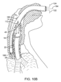
図10Aは、ヒトの身体通路に挿入されたときの装置100の作業端102の一例を示す図である。この例では、装置は気管18に挿入され、装置100は上述したように気道にあることを検知する。しかしながら、図10Bに示すように、装置100の変形例は、上述したプロセスを用いて食道16に配置することもでき、食道16を一時的にシールして呼吸通路18へ空気を送り出すことが可能である。
Figure 10A illustrates an example of the working
いずれの場合も、装置100は、予め定められた速度で空気のボーラス40を供給することにより支援換気を開始するように構成されている。胸腔内の圧力PTまたは胸部圧迫による胸腔に印加される力Fによって、胸腔内の状態を測定して胸腔内の変化を判断する装置100が構成される。後者の場合、胸部に加わる力Fによって組織(気管などの組織)に動きが生じ、この動きは、上述した力検知要素190によって判断することができる。圧力PTの変化などの流体特性の測定による胸腔内の可能性の検知は、通常、身体通路(気管18や食道16など)内で測定される。このような測定には、空気の流速、体積、圧力などの測定が含まれ得る。
In either case, the
一態様において、初期速度または事前に予め定められた速度は、毎分100回の換気からなる(すなわち、空気のボーラスが毎分100回送り出される)。しかしながら、どのような送達速度でも本開示の範囲内にある。通常胸部圧迫による胸腔内の状態変化を検知すると、最適な結果が得られるように、装置100は、送気のタイミングおよび速度のうちの少なくともいずれか一方を調整する。例えば、システムは、胸部圧迫を検知すると(力の測定または流体センサーの測定によって)、空気のボーラスを供給することができる。この場合、空気の入ったボーラスは胸腔内の圧力を高め、胸部内圧として心臓および肺を内側から圧迫し、血流を増加させる。
In one aspect, the initial or pre-determined rate comprises 100 ventilations per minute (i.e., 100 boluses of air are delivered per minute). However, any delivery rate is within the scope of the present disclosure. Upon sensing a change in intrathoracic conditions, typically due to chest compressions, the
本装置の変形例では、システムは、胸腔の状態の変化を連続的に、または遅延して監視する。いずれの場合も、空気のボーラスの送達による胸腔内圧の変化には反応しないように構成することができる。例えば、システムは、空気のボーラスの送達中や送達直後の読み取り値を無視することができる。 In variations of the device, the system monitors changes in thoracic condition continuously or with a delay. In either case, the system can be configured to not react to changes in intrathoracic pressure due to delivery of the air bolus. For example, the system can ignore readings during or immediately after delivery of the air bolus.
胸部圧迫の特定の段階に対応して空気のボーラスの供給を(タイミングおよび速度のうちの少なくともいずれか一方によって)調整するプロセスは、CPR中に使用することを意図したものである。しかしながら、支援換気は、機械的な圧迫システムを使っても、従事者が手動で胸部圧迫を行っても達成することができる。 The process of regulating (by timing and/or rate) the delivery of a bolus of air in response to a particular phase of chest compression is intended for use during CPR. However, assisted ventilation can be achieved with either a mechanical compression system or manual chest compressions by the practitioner.
タイミングおよび速度のうちの少なくともいずれか一方の変更は、患者の胸部の圧迫の各々または特定の回数および特定の位相で空気のボーラスを提供することを意図している。本明細書で述べたように、換気は、胸部圧迫のダウンストローク中に胸腔内圧を上昇させ、心臓への圧力を増加させて血流を増加させることによって、胸部圧迫の効率を高める方法でタイミング設定されている。圧迫のアップストロークの間、新しい空気が肺胞に入るように換気の一部を行い、圧迫のアップストロークの一部は胸腔内負圧を作り出し、血液を心臓に戻し、空気を肺胞に入れるようにすることができる。また、この技術により、救助者は、換気をするために圧迫を中断する必要がないため、血流が悪くなり、患者の生存率が低下することを防止することができる。 The timing and/or rate changes are intended to provide a bolus of air at each or a specific number and specific phase of the patient's chest compressions. As described herein, ventilation is timed in a manner that increases the efficiency of chest compressions by increasing intrathoracic pressure during the downstroke of chest compressions, increasing pressure on the heart and increasing blood flow. Part of the ventilation can be during the upstroke of compressions to allow new air to enter the alveoli, and part of the upstroke of compressions can create negative intrathoracic pressure to return blood to the heart and allow air to enter the alveoli. This technique also allows the rescuer to avoid having to interrupt compressions to provide ventilation, which can lead to poor blood flow and reduced patient survival.
本明細書に記載された装置を使用する場合、装置が気管または食道のどちらに配置されるかにかかわらず、気道は常に外部環境に開放されており、これにより、気圧性外傷の可能性を排除しないまでも、大幅に低減することができる。 When using the devices described herein, regardless of whether the device is placed in the trachea or esophagus, the airway is always open to the outside environment, which greatly reduces, if not eliminates, the possibility of barotrauma.
深さ、速度、反動時間に関する圧迫の効率に関して本明細書に記載した装置によって生成されたデータは、圧迫の効率を最大化するために、分析され、従事者にフィードバックを介して提示されることが可能である。これらの情報はすべて、圧迫の効率を上げ、これにより患者の血流を増加させ、患者の生存率を高めるために利用される。機械式圧縮システムを使用する場合、サイクル位相は装置100に直接リンクさせることが可能である。
Data generated by the devices described herein regarding the efficiency of compressions in terms of depth, speed, and recoil time can be analyzed and presented via feedback to the practitioner to maximize the efficiency of compressions. All of this information is utilized to increase the efficiency of compressions, thereby increasing the patient's blood flow and improving the patient's chances of survival. When using mechanical compression systems, the cycle phase can be linked directly to the
さらに、胸部圧迫が停止/一時停止した場合、予め設定した空気のボーラスの供給速度に戻るようにシステムを構成することができる。その場合、システムは、胸腔内の変化が検知されない時間の量を監視することができる。予め設定された時間、変化が検知されない場合、制御ユニットは、支援換気の速度を初期速度または胸部圧迫に左右されない代替速度にリセットすることができる。加えて、患者の脈拍が戻った場合には、システムは、予め設定した速度や量などで支援換気を継続することができる。これに代えて、システムは、従事者が要求に応じて支援換気を行うことができる手動モードに入ることができる(例えば、手動トリガーボタンを使用して)。さらに、システムは、患者の脈拍を確認し、脈拍の識別を利用して、支援換気の速度を調整したり、支援換気を停止したりするように構成することもできる。 Furthermore, the system can be configured to return to a preset rate of delivery of the bolus of air if chest compressions are stopped/paused. In that case, the system can monitor the amount of time during which no change in the thoracic cavity is detected. If no change is detected for the preset time, the control unit can reset the rate of assisted ventilation to the initial rate or an alternative rate that is not dependent on chest compressions. In addition, if the patient's pulse returns, the system can continue assisted ventilation at the preset rate, amount, etc. Alternatively, the system can be placed into a manual mode (e.g., using a manual trigger button) that allows the attendant to provide assisted ventilation on demand. Furthermore, the system can be configured to check the patient's pulse and use pulse identification to adjust the rate of assisted ventilation or to stop assisted ventilation.
手動トリガーにより、一旦患者が脈拍を取り戻したときに、従事者がオンデマンドのボタンにより制御された換気を行うことができ、これは、外部胸部圧迫の必要性をなくすことができ、有用である。上述したように、装置100は、吸引で食道を潰すことによって肺の隔離をなお継続することができ、かつ/または適切なルーメンを通して肺に空気を直接送ることができるが、換気を従事者によって与えられる要求に応じて与えられる空気ボーラスに変更する。手動トリガーにより、従事者が肺への空気の流れを開始させることができる。トリガーを離すと、肺への空気の流れが止まり、患者は息を吐くことができる。これに代えて、トリガーを1回操作するだけで、予め設定された量の空気を送り、患者を換気することも可能である。
The manual trigger allows the practitioner to provide on-demand, button-controlled ventilation once the patient regains a pulse, which can be useful in eliminating the need for external chest compressions. As described above, the
また、本明細書に記載のシステムは、従来の救命装置と組み合わせて使用することもできる。例えば、換気システムは、活性胸部圧迫装置と協働するように構成することができ、これにより、換気と胸部圧迫とのタイミングを合わせて、圧迫および換気の両者の有効性を高めることができる。結合は、機械的および電気的なもののうちの少なくともいずれか一方であり得る。換気システムは、本明細書に記載されるように、二酸化炭素レベルが信号または気体の流れを介してモニターまたは他の通知手段に出力されるように、二酸化炭素のサンプリングをさらに含むことができる。 The systems described herein may also be used in combination with conventional life support devices. For example, the ventilation system may be configured to cooperate with an active chest compression device, thereby allowing timing of ventilation and chest compressions to increase the effectiveness of both compressions and ventilation. The coupling may be mechanical and/or electrical. The ventilation system may further include carbon dioxide sampling, as described herein, such that the carbon dioxide level is output via a signal or gas flow to a monitor or other notification means.
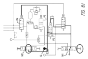
図11Aおよび図11Bは、本明細書に記載されるような酸素源を用いてヒトを人工的に換気するための一態様によるシステムを示す図である。図示の例では、制御システム150が、どのようにシステムインターフェース152を介して制御可能なファームウェアを有する電気制御システムを有するスタンドアロンユニットとして使用できるか、またはどのように外部装置(例えば、心臓モニター、モニター/除細動器、あるいはその他の重要医療装置)と一体的に設けられるか若しくは制御できるかを明確に説明するために、装置100は図示されていない。図示のように、制御ユニット150は、外部装置162に取り付けられ、酸素源160に結合されることが可能である。図11Bに示すように、一旦外部装置162に結合されると、制御ユニット150は搭載型制御部152を用いて操作でき、または無線若しくは有線接続により外部装置162を介して制御できる。その場合、図11Cに示すように、制御ユニット150の搭載型制御部152の1つ以上を、外部装置162の制御部/表示部164上に表示できるようにする。図11Cに示す態様は、CPRモード、オンデマンドモード、または吸引モードで装置100を作動させるための制御部を示す図である。ただし、制御部/ディスプレイ164および/または搭載型制御部152には、任意の数の項目を表示することができる。
11A and 11B are diagrams illustrating a system according to one embodiment for artificially ventilating a human using an oxygen source as described herein. In the illustrated example, the
例えば、装置100は、CPR中の胸部圧迫の位相、速度、効率、深さ、比率に関連する情報を表示することができる。加えて、本装置は、音声または視覚的なフィードバックによって支援圧迫の効率について操作者にリアルタイムでフィードバックするための情報の他、手動圧迫の速度を上げるか下げるか、脈がなくなった場合または従事者が胸部圧迫を停止した時間が長すぎる場合に胸部圧迫を再開するかどうかに関する情報を表示することができる。
For example,
装置100は、外部装置162と結合したときに充電できる充電式電源で構成することもでき、また、接続により一般的なAC電源で装置100を充電できるようにすることも可能である。多くの場合、制御ユニット150は、十分な動作時間および十分なスタンバイ時間を確保できるように装置を駆動可能な電源を搭載している。
The
図12は、制御ユニット150の携帯性を高めるための追加の改善策を示す図である。この構成では、制御ユニット150は、酸素源160に依存して、ヒトへの換気の他、上述した真空の生成を行う。従って、酸素の供給源を拡張するために、装置は、1つ以上の真空弁200、202を採用し、酸素の加圧流量の結果として真空を発生させ、1つの真空弁を高流量で作動させて吸引を発生させることが可能である。一旦一定時間真空状態が続くと、システムは、低流量で高真空を発生させる低流量真空弁202に切り替わることができる。このような構成にすることで、酸素供給部の寿命が延びる。
Figure 12 illustrates an additional improvement to enhance the portability of the
別例では、本明細書に記載の装置は、異なるサイズに対応するチューブを用いて換気パラメーターを決定するために使用することができる。例えば、装置は、小児用としてブロスローテープ(Broselow Tape)と均等の、異なるサイズの様々な作業端を有する。これにより、従事者は気道およびブロスローテープが推奨するサイズのものを選択するとともに人工呼吸器にこれを装着するのみでよい。認証プロセスにより、選択された気道に基づく患者のおおよその大きさが人工呼吸器に通知されるため、従事者は換気パラメーターを調整する必要がない。これに代えて、気道そのものが、患者が受ける容積、圧力、吸引圧を低減し得る。この方法の一例として、換気チューブの幅を狭くして流れを制限し、一定期間の換気量を少なくすることが挙げられる。別例による排気弁は余分な量の換気を大気中に排出し、患者の換気量および圧力の両者を低減するものである。 In another example, the device described herein can be used to determine ventilation parameters using tubes that correspond to different sizes. For example, the device has a variety of working ends of different sizes, equivalent to Broselow Tape for pediatric use. This allows the practitioner to simply select the airway and the size recommended by the Broselow Tape and attach it to the ventilator. The authentication process informs the ventilator of the approximate size of the patient based on the selected airway, so the practitioner does not need to adjust ventilation parameters. Alternatively, the airway itself may reduce the volume, pressure, and suction pressure the patient receives. One example of this method is to narrow the ventilation tube to restrict flow and reduce the amount of ventilation for a period of time. Another example exhaust valve vents the excess amount of ventilation to the atmosphere, reducing both the amount of ventilation and the pressure of the patient.
本明細書に記載された方法により、様々な方法を介して患者の口、食道に置かれたチューブの曲がりを検知することによって、CPR中の胸部圧迫の位相、速度、効率、深さ、比率を測定することができる。チューブ上の歪みゲージ、光ファイバー、空気の動きセンサーなどを含むが、これらに限定されるものではない。この方法の別例には、十分な気体交換を可能にしながらCPRの効率を最大にするために、圧迫のある段階で換気のタイミングを計ることも含まれる。この方法の別例には、圧迫を停止または一時停止した後に換気を継続することが含まれる。また、この方法は、音声または視覚的なフィードバックにより、救助者の圧迫の効率に関するリアルタイムのフィードバックを操作者に提供することができる。本明細書に記載の方法は、本明細書に記載の人工呼吸器を使用することができ、または任意の換気装置を使用することができる。 The methods described herein can measure the phase, rate, efficiency, depth, and rate of chest compressions during CPR by sensing bending of a tube placed in the patient's mouth, esophagus, through various methods, including but not limited to strain gauges on the tube, fiber optics, air movement sensors, and the like. Alternatives to the method include timing ventilation during certain phases of compressions to maximize the efficiency of CPR while allowing adequate gas exchange. Alternatives to the method include continuing ventilation after stopping or pausing compressions. The method can also provide real-time feedback to the operator regarding the efficiency of the rescuer's compressions through audio or visual feedback. The methods described herein can use the ventilators described herein, or can use any ventilation device.
上記のシステムの特徴としては、チューブ上に電極を配置し、口、食道、気管に入れたチューブを通して心臓をペーシングする方法;患者の口、気管、食道のチューブに配置した電極を介して心臓を除細動する方法;患者の口、気管、食道のチューブを通して患者に脈拍や心臓の機械的収縮があるかどうかを判断する方法などが挙げられる。 Features of the above system include pacing the heart through a tube placed in the mouth, esophagus, or trachea with electrodes on the tube; defibrillating the heart through electrodes placed in a tube in the patient's mouth, trachea, or esophagus; and determining whether the patient has a pulse or mechanical contractions of the heart through a tube in the patient's mouth, trachea, or esophagus.
図19乃至28は、患者の口、気管または食道に設置された気道のチューブ上に配置された抵抗器により、胸部圧迫の位相、速度、深さおよび効果を検知する回路の一例を示す図である。その情報は救助者に伝えられるほか、弁に信号を送信して換気のタイミングを計ることもできる。これは、上述した発明を実施する方法の一例に過ぎず、上述した他の方法を限定するものではない。 Figures 19-28 show an example of a circuit that detects the phase, rate, depth and effect of chest compressions using resistors placed on an airway tube placed in the patient's mouth, trachea or esophagus. This information can be communicated to a rescuer and/or a signal can be sent to a valve to time ventilation. This is only one example of a method of practicing the invention described above and is not intended to be limiting of the other methods described above.
さらなる一態様において、本システムは、胸腔内の圧力の微妙な変化を高速で監視することも可能である。例えば、システムは、装置の作業端に沿った圧力や装置の遠位端での圧力を監視することで、胸腔内の圧力を連続的に監視することができる。このシステムは、あらゆる圧力変化に対して迅速な反応を引き起こすことができる。例えば、システムが圧力変化を検知しない場合(または検知された圧力変化が予め定められた閾値を下回る場合)、システムは設定された速度で患者を換気し、確実に胸部圧迫を同時に行わずに換気することができる。 In a further aspect, the system is also capable of rapid monitoring of subtle changes in intrathoracic pressure. For example, the system can continuously monitor intrathoracic pressure by monitoring pressure along the working end of the device and pressure at the distal end of the device. The system can trigger a rapid response to any pressure change. For example, if the system does not detect a pressure change (or if the detected pressure change is below a predefined threshold), the system can ventilate the patient at a set rate, ensuring ventilation without simultaneous chest compressions.
現在のシステムでは、呼吸をしようとする患者を換気する必要はない。その代わりに、本システムでは、ヒトの胸部内圧力を監視して、供給される換気のタイミングおよびパラメーターを調整する。例えば、本システムは、ヒトの胸腔内の圧力を監視する「CPRモード」を含むことができる。システムは胸腔内の圧力を測定し、この測定値を用いて患者の胸部圧迫の有無を判断することができる。胸部圧迫を検知すると、システムは換気を停止することができる。これに代えて、胸部圧迫の測定により胸部圧迫が行われていないことが判明した場合、システムは設定した速度で換気を行い、確実に患者を換気することができる。 Current systems do not require ventilation of a patient attempting to breathe. Instead, the system monitors the intrathoracic pressure of a person to adjust the timing and parameters of the ventilation delivered. For example, the system may include a "CPR mode" that monitors the pressure within the person's thoracic cavity. The system may measure intrathoracic pressure and use this measurement to determine whether the patient is undergoing chest compressions. If chest compressions are detected, the system may stop ventilation. Alternatively, if the chest compression measurement indicates that chest compressions are not occurring, the system may ventilate at a set rate to ensure the patient is ventilated.
また、この自動非トリガー式換気により、胸部圧迫の開始または再開時に胸腔内の空気が確実に確保されるため、システムは胸部圧迫をより容易に検知することができる。この構成の一利点は、換気システムが、換気をトリガーする患者の呼吸の試みに左右されないことにある。本システムは、患者が呼吸をすることに左右されず、医療従事者が胸を圧迫することに依存する。本システムは、胸部の陽圧および陰圧の両者の変化を利用して、タイミングおよび換気パラメーターを調整することができる。 This automatic non-triggered ventilation also ensures that there is air in the thoracic cavity when chest compressions begin or resume, allowing the system to more easily detect chest compressions. One advantage of this configuration is that the ventilation system does not depend on the patient attempting to breathe to trigger ventilation. The system does not depend on the patient breathing, but rather on the medical personnel compressing the chest. The system can use changes in both positive and negative chest pressure to adjust timing and ventilation parameters.
現在のシステムの変形例は、気道の他、換気装置の非常に微妙な圧力変化も検知することができる。上述したように、従来の換気システムは、患者自身の呼吸を圧力変化で検知しているため、肺内の圧力を大きく変化させる必要がある。本システムの変形例では、小さいかまたは微妙な圧力変化を検知する能力により、開胸腔(すなわち、肺がバルーンまたは他の隔離装置を介して大気から隔離されていない)を生じる胸部圧迫に関連付けられるより小さな圧力変化をシステムが検知することができる。本システムは、また、同じ圧力センサーラインを使用して、心臓の収縮に関連付けられる胸腔内の微妙な圧力変化を検知することも可能である。 A variation of the current system is able to detect very subtle pressure changes in the airway as well as the ventilator. As mentioned above, conventional ventilation systems rely on pressure changes to detect the patient's own breathing, which requires large changes in pressure within the lungs. In this variation of the system, the ability to detect small or subtle pressure changes allows the system to detect the smaller pressure changes associated with chest compressions that create an open chest cavity (i.e., the lungs are not isolated from the atmosphere via a balloon or other isolation device). Using the same pressure sensor lines, the system is also able to detect subtle pressure changes within the chest cavity associated with cardiac contractions.
本システムの一変形例は、活性換気チューブから挿管装置の作用遠位端まで独立して移動する専用の小径(例えば、1mm以下)を含む。この分離したルーメンは、装置の作業端で再び接続される。このような構成により、人工呼吸器のベンチュリーの影響を受けることなく、患者の体内の圧力をサンプリングすることができる。また、この構成により、患者の体内の圧力の読み取り精度が向上する。そのため、システムは、胸部圧迫および心臓の収縮のうちの少なくともいずれか一方に関連付けられる僅かな圧力の変化も、より正確に、かつより敏感に検知することができるようになる。 One variation of the system includes a dedicated small diameter (e.g., 1 mm or less) lumen that travels independently from the active ventilation tube to the working distal end of the intubation device. This separate lumen reconnects at the working end of the device. This configuration allows the pressure inside the patient to be sampled without the influence of the venturi of the ventilator. This configuration also improves the accuracy of the pressure reading inside the patient, allowing the system to more accurately and sensitively detect small pressure changes associated with chest compressions and/or cardiac contractions.
また、個別の圧力を使用することで、従来の機器に比べ、別の利点もある。例えば、従来の装置では、内径5mm程度の成人用シングルルーメンチューブから25mm程度の接続チューブを使用し、そのチューブが3乃至7フィート(約0.91乃至2.13メートル)移動して通常圧力センサーを内包する人工呼吸器に接続される。微妙な圧力変化(0.005~1.0cmH20)をサンプリングし、その信号をセンサーに伝えることは困難である。また、現在の換気用チューブおよびコネクターの多くは、患者から人工呼吸器までの移動に伴い直径が大きくなっている。この直径が大きくなると、信号が減衰してしまうのである。上述したように、センサーが換気用のルーメンと同じルーメンを共有している場合、移動する換気用空気のベンチュリー効果により、圧力読み取り値が変動し、信頼性が低くなる。特に、ジェット換気技術を利用する場合は、その傾向が顕著である。また、換気圧が発生する人工呼吸器の上流部分と、下流側の気道遠位端で測定される圧力との間には通常差圧がある。装置の遠位端での圧力の測定は、通常、患者の体内の圧力に対応する。 The use of separate pressures also offers other advantages over conventional devices. For example, conventional devices use a 5mm inner diameter adult single lumen tube with a 25mm inner diameter connecting tube that travels 3-7 feet to a ventilator that typically contains a pressure sensor. It is difficult to sample the small pressure changes (0.005-1.0 cmH20) and transmit the signal to the sensor. Also, many of the current ventilation tubes and connectors increase in diameter as they travel from the patient to the ventilator. This increases the signal attenuation. As mentioned above, if the sensor shares the same lumen as the ventilation lumen, the Venturi effect of the moving ventilation air will cause the pressure reading to fluctuate and become unreliable, especially when jet ventilation technology is used. Also, there is usually a pressure difference between the upstream portion of the ventilator where the ventilation pressure is generated and the pressure measured at the downstream distal end of the airway. The pressure measurement at the distal end of the device usually corresponds to the pressure inside the patient.
本明細書で述べたように、本発明の装置は、心停止を経験している患者を支援するために使用することができる。このような場合、患者の動脈に触知可能な血流があるかどうかを判断することが重要である。これは、通常、医療従事者が患者の橈骨動脈、大腿動脈、頸動脈に脈を感じようとし、心電図装置での心臓の電気的な読み取り値と関連付けることによって行われる。しかしながら、救急の現場では触診で圧力を識別することは困難である。また、電気信号が患者の心臓の組織を伝わり、心臓が収縮する場合もあるが、収縮が不十分で血圧に大きな変化が生じない場合もある。この状態を無脈性電気活動(PEA)と呼ぶ。心臓の筋収縮をもたらすPEAか、心筋収縮を伴わない電気信号かを医療従事者が区別することが重要である。患者の処置法を決定する上で、病態の特定は重要である。現在、これらを区別するためには、医療従事者が患者の心臓の電気信号を監視し、超音波などの精密な画像診断で心臓を見つけ出した後に電気信号に関連する筋肉の動きを判断する必要がある。本明細書に記載された装置の構成により、心臓の筋収縮に関連付けられる圧力変化から生じる胸腔内の圧力変化を測定することができる。本装置は、続いて心電図の読み取り値(別の心電図装置を通じてか、本装置に含まれているか)を用いて、これらの圧力変化が心臓の収縮と関連付けられているかどうかを判断することができる。この情報を続いて医療従事者に伝えることで、追加の画像装置や医療評価を必要とせず、患者の処置法を決定することができる。また、気道や食道の圧力変化を測定して心臓の収縮を検知すると、音声または視覚的なプロンプトで中継され、これにより、医療従事者はプロンプトと任意の心電図信号とを比較することができる。 As described herein, the device of the present invention can be used to assist a patient experiencing cardiac arrest. In such cases, it is important to determine whether there is palpable blood flow in the patient's arteries. This is typically done by a medical professional attempting to feel a pulse in the patient's radial, femoral, and carotid arteries and correlating it with an electrical reading of the heart from an electrocardiogram machine. However, in an emergency setting, it is difficult to identify pressure by palpation. Also, while electrical signals may travel through the tissues of the patient's heart, causing the heart to contract, other times the contraction is insufficient to cause a significant change in blood pressure. This condition is called pulseless electrical activity (PEA). It is important for medical professionals to distinguish between PEA, which results in muscle contraction of the heart, and electrical signals without myocardial contraction. Identifying the pathology is important in determining how to treat the patient. Currently, to distinguish between these, medical professionals must monitor the electrical signals of the patient's heart and determine the muscle movement associated with the electrical signals after locating the heart with precise imaging such as ultrasound. The device configuration described herein allows for the measurement of pressure changes within the thoracic cavity resulting from pressure changes associated with muscle contraction of the heart. The device can then use electrocardiogram readings (either through a separate electrocardiogram device or included in the device) to determine whether these pressure changes are associated with cardiac contractions. This information can then be communicated to medical personnel to determine how to treat the patient without the need for additional imaging devices or medical evaluation. Additionally, the detection of cardiac contractions by measuring airway and esophageal pressure changes is relayed with audio or visual prompts that allow medical personnel to compare the prompts to any electrocardiogram signals.
本明細書に記載された装置の追加の変形例は、救急治療中に心臓組織の電気刺激を提供することもできる。電気刺激は、心室細動の致命的なリズムまたは無脈性心室性頻拍のいずれかをリセットするために使用することができる。また、心臓の拍動が遅い場合や不規則な場合は、電気刺激で心臓を余分に収縮させることもできる。現在、救急医療では、胸部や背部のさまざまな箇所に設置された外部ペーシングパッドを用いて心臓を電気刺激することがほとんどである。これらの外部パッドは、心臓を捕捉するために十分なエネルギーを体内に通過させる必要がある。他の組織/臓器のインピーダンスの関係で、外部パッドには360ジュール(N・m)を超えるエネルギーが必要な場合が多い。これに代えて、本装置は、チューブが食道と接触する装置の遠位側チューブに1つ以上の除細動電極を含むことができる。このように電極を心臓に近づけて配置することで、外部電極が遭遇するインピーダンスを低減することができる。これにより、本装置を用いて電気刺激を加えることで、より少ないエネルギーで効率的に心臓の組織を電気刺激することができる。吸引して食道を電極に接触させることで、パッドと食道の組織とが確実に適切に接触する。第2のパッドは、同じチューブに沿って、または胸部の任意の部位上に配置することができる。 Additional variations of the devices described herein can also provide electrical stimulation of cardiac tissue during emergency care. Electrical stimulation can be used to reset either the fatal rhythm of ventricular fibrillation or pulseless ventricular tachycardia. Electrical stimulation can also stimulate the heart to perform extra contractions if the heart is beating slowly or irregularly. Currently, emergency care mostly involves electrical stimulation of the heart using external pacing pads placed at various points on the chest or back. These external pads must pass enough energy into the body to capture the heart. External pads often require more than 360 Joules (Nm) of energy due to impedance of other tissues/organs. Alternatively, the device can include one or more defibrillation electrodes on the distal tube of the device where the tube contacts the esophagus. This placement of the electrodes closer to the heart reduces the impedance encountered by the external electrodes. This allows electrical stimulation to be applied with the device to efficiently stimulate cardiac tissue with less energy. Suction is used to contact the electrodes in the esophagus to ensure proper contact between the pads and the esophageal tissue. The second pad can be placed along the same tube or anywhere on the chest.
本明細書に記載される装置の変形は、成人の気道のための異なるサイズの範囲に調整するように構成される。しかしながら、小児用途では、個々の小児患者に応じて換気および吸引のパラメーターを変更するのみならず、換気装置を様々なサイズで提供することができる。本装置は、装置の使い捨て構成要素(例えば、チューブまたはマスク)上に検証チップを含むことができ、検証チップが制御ユニット(例えば、図3Aの150を参照)によって読み取られると、制御ユニットは、換気装置が承認されたベンダーによって製造された単回使用の装置であることを確認することができる。この同じ検証チップを使用することで、換気システムは小児用換気装置の特定のサイズを決定し、それに応じて換気固有のパラメーターを調整することも可能である。 The device variations described herein are configured to adjust to a range of different sizes for adult airways. However, for pediatric applications, the ventilator may be provided in a variety of sizes, as well as modifying ventilation and suction parameters for individual pediatric patients. The device may include a validation chip on a disposable component of the device (e.g., tubing or mask) that, when read by a control unit (see, e.g., 150 in FIG. 3A), may enable the control unit to verify that the ventilator is a single-use device manufactured by an approved vendor. Using this same validation chip, the ventilation system may also determine the specific size of the pediatric ventilator and adjust ventilation-specific parameters accordingly.
図23A乃至23Cは、装置100の周囲に配置される潤滑剤ハウジング210を有する、別例による装置100を示す図である。潤滑剤ハウジング210は、潤滑剤源220、気管内チューブに使用されるゲル潤滑剤を含む。潤滑剤源220は、ハウジング210内に配置され、レバーアーム216に隣接している。レバーアーム216は、ハウジング210内に枢動可能に結合されるように構成されている。例えば、レバーアーム216は、ハウジング210内におけるレバーアーム216の移動を許容するヒンジ部217を含むことができる。図示の態様では、ハウジング210は、レバーアーム216(図23Bに示す)に結合され得る穿刺部材218を受承する1つ以上の開口部214を含む。図23Cは、レバーアーム216が潤滑供給物(図示しない)に対して駆動される一例を示しており、ここで、穿刺部材218は供給部を穿刺し、ハウジング210内の開口部214を通って延びる。レバーアーム216は、矢印222で示すように、装置100からのハウジング本体210の取り外しの際に供給部220を圧縮するように構成され得る。レバーアーム216は、任意のカム/フォロワー構造体、または潤滑供給部220の不注意な圧縮を防止する任意の構造体によって駆動することができる。一旦潤滑供給部220が穿刺されると、装置からハウジング本体210を取り外すことにより、装置210のシャフトがシャフトの一部または全長に沿って潤滑ゲルで被覆される。追加の構成では、ゲルは、潤滑物質の代わりに、または潤滑物質に加えて、抗菌物質を含む。
23A-23C illustrate another example of the
上述したものは、単に本発明の原理を説明したに過ぎない。当業者であれば、本明細書に明示的に記載または示されていないものの、本発明の原理を具現化し、その趣旨および範囲に含まれる様々な構成を考案できることが理解されよう。さらに、本明細書に記載されたすべての例および条件文は、主として、読者が本発明の原理および当該技術分野を促進するために本発明者らが貢献した概念を理解するのを助けることを目的としており、かかる具体的に記載された例および条件に限定されるものではないと解釈される。さらに、本発明の原理、態様、および実施形態、並びにその具体例を示す本明細書のすべての記述は、その構造的均等物および機能的均等物の両者を包含することを意図している。加えて、このような均等物には、現在周知の均等物および将来開発される均等物の両者、すなわち、構造に関係なく同じ機能を果たすあらゆる開発される要素が含まれることが意図される。したがって、本発明の範囲は、本明細書に示され、説明される例示的な実施形態に限定されることを意図するものではない。むしろ、本発明の範囲および趣旨は、添付の特許請求の範囲によって具現化される。 The foregoing merely illustrates the principles of the present invention. It will be appreciated that those skilled in the art can devise various configurations that embody the principles of the present invention and are within the spirit and scope of the present invention, although not expressly described or shown herein. Furthermore, all examples and conditional statements described herein are intended primarily to aid the reader in understanding the principles of the present invention and the concepts contributed by the inventors to advance the art, and are not intended to be limited to such specifically described examples and conditions. Furthermore, all statements herein that set forth principles, aspects, and embodiments of the present invention, as well as specific examples thereof, are intended to encompass both structural and functional equivalents thereof. In addition, such equivalents are intended to include both currently known equivalents and equivalents developed in the future, i.e., any elements developed that perform the same function regardless of structure. Thus, the scope of the present invention is not intended to be limited to the exemplary embodiments shown and described herein. Rather, the scope and spirit of the present invention is embodied by the appended claims.
より具体的には、本明細書および添付の特許請求の範囲で使用されているように、単数形の「a」、「an」、「said」、および「the」は、文脈が明らかに他を指示しない限り、複数の参照を含む。したがって、例えば、「ストリング」への言及は、複数のそのようなストリングを含み、「管状部材」への言及は、1本以上の管状部材および当業者に周知のその均等物への言及を含む、などである。 More specifically, as used herein and in the appended claims, the singular forms "a," "an," "said," and "the" include plural references unless the context clearly dictates otherwise. Thus, for example, a reference to a "string" includes a plurality of such strings, a reference to a "tubular member" includes a reference to one or more tubular members and equivalents thereof known to those skilled in the art, and so forth.
値の範囲が設けられている場合、文脈上明らかにそうでない場合を除き、その範囲の上限と下限との間に介在する各値、下限の単位の10分の1も具体的に開示されていると理解される。記載された範囲内の任意の記載値または介在値と、その記載範囲内の任意の他の記載値または介在値との間の各より小さな範囲は、本発明に包含される。これらのより小さい範囲の上限および下限は、独立して範囲に含まれることも除外されることもでき、いずれか、または両者の限界がより小さい範囲に含まれる各範囲も、いずれの限界も含まれない各範囲も、記載の範囲において特に除外される限界を条件として、本発明内に包含される。記載された範囲が限界値の一方または両者を含む場合、それらの含まれる限界値の一方または両者を除いた範囲も本発明に含まれる。 Where a range of values is provided, unless the context clearly indicates otherwise, it is understood that each intervening value between the upper and lower limits of that range, and each tenth of the unit of the lower limit, is specifically disclosed. Each smaller range between any stated or intervening value in a stated range and any other stated or intervening value in that stated range is encompassed within the invention. The upper and lower limits of these smaller ranges may be independently included or excluded, and each range in which either or both limits are included in the smaller range, and each range in which neither limit is included, is also encompassed within the invention, subject to the limit specifically excluded in the stated range. When a stated range includes one or both of the limits, ranges excluding one or both of those included limits are also encompassed within the invention.
本明細書で言及したすべての刊行物は、その刊行物が引用されている方法および材料のうちの少なくともいずれか一方に関連して開示および説明するために、その全体が本明細書に開示されたものとする。本明細書で論じた刊行物は、本出願の出願日前の開示のためにのみ提供されるものである。本明細書のいかなる内容も、本発明が先行発明によりかかる公開に先行する権利を有しないことを認めるものと解釈されないものとする。また、公開日が実際の公開日と異なる場合があり、これは、別途確認が必要な場合がある。 All publications mentioned herein are incorporated herein in their entirety to disclose and describe the methods and/or materials in connection with which the publications are cited. The publications discussed herein are provided solely for their disclosure prior to the filing date of the present application. Nothing herein should be construed as an admission that the present invention is not entitled to antedate such publication by virtue of prior invention. Additionally, the publication dates may be different from the actual publication dates, which may require independent confirmation.
Claims (10)
前記ヒトの呼吸口内に挿入されるように構成され、前記ヒトの身体通路内に配置するための作業部を有する換気装置を備え、
前記換気装置は、前記作業部に露出した圧力ルーメンを有し、前記圧力ルーメンは、前記圧力ルーメンを用いて前記身体通路内の圧力変化を検知するように構成されたセンサーと流体連通し、
前記換気装置は、前記ヒトを換気するために前記作業部を通して空気のボーラスを供給するように構成された制御システムを有し、
前記制御システムは、前記胸部圧迫の結果生じる前記身体通路内の前記圧力変化を検知すると、前記空気のボーラスの送達タイミングを変更し、かつ、血流を増加させるために体積を増加させた空気のボーラスを送達して前記胸部圧迫後に前記ヒトの胸腔をさらに再膨張させるように構成され、
前記システムは、予め定められた閾値を下回る圧力変化の検出したときに、設定された速度で前記ヒトを換気する、システム。 1. A system for providing ventilation and increasing efficiency of chest compressions in a human, comprising:
a ventilation device configured to be inserted into the person's breathing opening, the ventilation device having a working portion for placement within the person's body passageway;
the ventilator has a pressure lumen exposed to the working portion, the pressure lumen in fluid communication with a sensor configured to sense pressure changes within the body passageway using the pressure lumen;
the ventilator having a control system configured to deliver a bolus of air through the working section to ventilate the person;
the control system is configured to, upon sensing the pressure change in the body passageway resulting from the chest compression, alter a timing of delivery of the bolus of air and deliver an increased volume bolus of air to increase blood flow to further re-inflate the person's thoracic cavity after the chest compression;
The system ventilates the person at a set rate upon detection of a pressure change below a predetermined threshold.
前記制御システムが、前記身体通路内の前記遠位側開口部を通して吸引し、同吸引を一定期間維持するように構成され、
前記制御システムは、前記身体通路が前記吸引によって前記遠位側開口部に対して引き寄せられるかどうかを判断し、前記身体通路が前記遠位側開口部に対して引き寄せられると判断できなかった後に、前記第1のルーメンを通して前記ヒトを換気するようにさらに構成され、前記身体通路が前記遠位側開口部に引き寄せられることを判断した後に、前記第2のルーメンを通して前記ヒトを換気し、前記第2のルーメンを通して換気しながら吸引を維持する、請求項1に記載のシステム。 the working portion includes a distal opening in fluid communication with the first lumen and an intermediate opening in fluid communication with the second lumen;
the control system is configured to apply suction through the distal opening in the body passageway and maintain the suction for a period of time;
2. The system of claim 1, wherein the control system is further configured to determine whether the body passage is drawn against the distal opening by the suction, and after failing to determine that the body passage is drawn against the distal opening, ventilate the person through the first lumen, and after determining that the body passage is drawn against the distal opening, ventilate the person through the second lumen, and maintain suction while ventilating through the second lumen.
Applications Claiming Priority (3)
| Application Number | Priority Date | Filing Date | Title |
|---|---|---|---|
| US201962896355P | 2019-09-05 | 2019-09-05 | |
| US62/896,355 | 2019-09-05 | ||
| PCT/US2020/049744 WO2021046537A1 (en) | 2019-09-05 | 2020-09-08 | Apparatus and method for improved assisted ventilation |
Publications (2)
| Publication Number | Publication Date |
|---|---|
| JP2022546558A JP2022546558A (en) | 2022-11-04 |
| JP7586897B2 true JP7586897B2 (en) | 2024-11-19 |
Family
ID=74852387
Family Applications (1)
| Application Number | Title | Priority Date | Filing Date |
|---|---|---|---|
| JP2022514213A Active JP7586897B2 (en) | 2019-09-05 | 2020-09-08 | Apparatus and method for improved assisted ventilation - Patents.com |
Country Status (6)
| Country | Link |
|---|---|
| US (2) | US12318539B2 (en) |
| EP (1) | EP4025282A4 (en) |
| JP (1) | JP7586897B2 (en) |
| AU (1) | AU2020341845B2 (en) |
| CA (1) | CA3149961A1 (en) |
| WO (1) | WO2021046537A1 (en) |
Families Citing this family (7)
| Publication number | Priority date | Publication date | Assignee | Title |
|---|---|---|---|---|
| SG11202110229PA (en) | 2019-03-21 | 2021-10-28 | Fisher & Paykel Healthcare Ltd | A respiratory device for providing bubble cpap |
| AU2020341845B2 (en) | 2019-09-05 | 2025-05-29 | Colabs Medical, Inc. | Apparatus and method for improved assisted ventilation |
| AU2020345575A1 (en) * | 2019-09-09 | 2022-04-21 | Fisher & Paykel Healthcare Limited | Respiratory therapy system and apparatus |
| USD940729S1 (en) | 2019-09-10 | 2022-01-11 | Fisher & Paykel Healthcare Limited | Display screen of a respiratory support apparatus or portion thereof with graphical user interface |
| US20230248931A1 (en) * | 2020-12-11 | 2023-08-10 | Blake J. Hyde | Irrigating cannula system |
| US11786683B2 (en) | 2020-12-11 | 2023-10-17 | Blake J. Hyde | Irrigating intraluminal suction inner cannula system |
| KR102612022B1 (en) * | 2023-08-09 | 2023-12-08 | 주식회사 장전 | Airway expansion device including safety fit structure |
Citations (2)
| Publication number | Priority date | Publication date | Assignee | Title |
|---|---|---|---|---|
| US20070137651A1 (en) | 2005-12-16 | 2007-06-21 | Ezc Medical Llc | Visualization esophageal-tracheal airway apparatus and methods |
| US20150297847A1 (en) | 2011-12-09 | 2015-10-22 | Colabs, Inc. | Apparatus and method for improved assisted ventilation |
Family Cites Families (11)
| Publication number | Priority date | Publication date | Assignee | Title |
|---|---|---|---|---|
| US3861395A (en) * | 1973-09-25 | 1975-01-21 | Tokuso Taniguchi | Automated catheter |
| US4148318A (en) | 1977-12-27 | 1979-04-10 | Abbott Laboratories | Tool for surgical preparations having an internal supply of antiseptic solution |
| US20060149128A1 (en) | 2005-01-05 | 2006-07-06 | Sightline Technologies Ltd. | Method and devices for lubricating an endoscopic surgical tool |
| US7527599B2 (en) | 2005-06-17 | 2009-05-05 | The Research Foundation Of State University Of New York | Method of determining cardiac indicators |
| SE533365C2 (en) | 2008-02-08 | 2010-09-07 | Igeloesa Life Science Ab | Cardiac rescue procedure and system |
| US20090277447A1 (en) * | 2008-05-12 | 2009-11-12 | Advanced Circulatory Systems, Inc. | System, method, and device to increase circulation during cpr without requiring positive pressure ventilation |
| US10201474B2 (en) * | 2008-09-12 | 2019-02-12 | Hugo Andres Belalcazar | Method and apparatus for improved ventilation and cardio-pulmonary resuscitation |
| US9586015B1 (en) * | 2013-09-17 | 2017-03-07 | Chance S. Lindner | Duty-cycle indicator for manual resuscitation/ventilation |
| CN203710505U (en) * | 2013-10-30 | 2014-07-16 | 陈宁 | Trachea and catheter lubricating device |
| AU2015230977A1 (en) * | 2014-03-21 | 2016-11-10 | Colabs Medical, Inc. | Apparatus and method for improved assisted ventilation |
| AU2020341845B2 (en) | 2019-09-05 | 2025-05-29 | Colabs Medical, Inc. | Apparatus and method for improved assisted ventilation |
-
2020
- 2020-09-08 AU AU2020341845A patent/AU2020341845B2/en active Active
- 2020-09-08 CA CA3149961A patent/CA3149961A1/en active Pending
- 2020-09-08 EP EP20860702.8A patent/EP4025282A4/en active Pending
- 2020-09-08 JP JP2022514213A patent/JP7586897B2/en active Active
- 2020-09-08 WO PCT/US2020/049744 patent/WO2021046537A1/en not_active Ceased
- 2020-09-08 US US17/014,904 patent/US12318539B2/en active Active
-
2025
- 2025-05-06 US US19/199,895 patent/US20250381354A1/en active Pending
Patent Citations (2)
| Publication number | Priority date | Publication date | Assignee | Title |
|---|---|---|---|---|
| US20070137651A1 (en) | 2005-12-16 | 2007-06-21 | Ezc Medical Llc | Visualization esophageal-tracheal airway apparatus and methods |
| US20150297847A1 (en) | 2011-12-09 | 2015-10-22 | Colabs, Inc. | Apparatus and method for improved assisted ventilation |
Also Published As
| Publication number | Publication date |
|---|---|
| US20210093814A1 (en) | 2021-04-01 |
| EP4025282A1 (en) | 2022-07-13 |
| US12318539B2 (en) | 2025-06-03 |
| WO2021046537A1 (en) | 2021-03-11 |
| US20250381354A1 (en) | 2025-12-18 |
| AU2020341845B2 (en) | 2025-05-29 |
| AU2020341845A1 (en) | 2022-04-14 |
| CA3149961A1 (en) | 2021-03-11 |
| EP4025282A4 (en) | 2023-09-06 |
| JP2022546558A (en) | 2022-11-04 |
Similar Documents
| Publication | Publication Date | Title |
|---|---|---|
| US11511061B2 (en) | Apparatus and method for improved assisted ventilation | |
| JP7586897B2 (en) | Apparatus and method for improved assisted ventilation - Patents.com | |
| US9802014B2 (en) | Apparatus and method for improved assisted ventilation | |
| JP7086900B2 (en) | Equipment for improved auxiliary ventilation | |
| US12364827B2 (en) | Apparatus and method for improved assisted ventilation |
Legal Events
| Date | Code | Title | Description |
|---|---|---|---|
| A521 | Request for written amendment filed |
Free format text: JAPANESE INTERMEDIATE CODE: A523 Effective date: 20220510 |
|
| A621 | Written request for application examination |
Free format text: JAPANESE INTERMEDIATE CODE: A621 Effective date: 20230905 |
|
| RD03 | Notification of appointment of power of attorney |
Free format text: JAPANESE INTERMEDIATE CODE: A7423 Effective date: 20230905 |
|
| RD04 | Notification of resignation of power of attorney |
Free format text: JAPANESE INTERMEDIATE CODE: A7424 Effective date: 20230906 |
|
| A521 | Request for written amendment filed |
Free format text: JAPANESE INTERMEDIATE CODE: A821 Effective date: 20230905 |
|
| A131 | Notification of reasons for refusal |
Free format text: JAPANESE INTERMEDIATE CODE: A131 Effective date: 20240226 |
|
| A521 | Request for written amendment filed |
Free format text: JAPANESE INTERMEDIATE CODE: A523 Effective date: 20240521 |
|
| A02 | Decision of refusal |
Free format text: JAPANESE INTERMEDIATE CODE: A02 Effective date: 20240531 |
|
| A521 | Request for written amendment filed |
Free format text: JAPANESE INTERMEDIATE CODE: A523 Effective date: 20240930 |
|
| A911 | Transfer to examiner for re-examination before appeal (zenchi) |
Free format text: JAPANESE INTERMEDIATE CODE: A911 Effective date: 20241010 |
|
| TRDD | Decision of grant or rejection written | ||
| A01 | Written decision to grant a patent or to grant a registration (utility model) |
Free format text: JAPANESE INTERMEDIATE CODE: A01 Effective date: 20241021 |
|
| A61 | First payment of annual fees (during grant procedure) |
Free format text: JAPANESE INTERMEDIATE CODE: A61 Effective date: 20241107 |
|
| R150 | Certificate of patent or registration of utility model |
Ref document number: 7586897 Country of ref document: JP Free format text: JAPANESE INTERMEDIATE CODE: R150 |