JP7586892B2 - Multi-element golf club head - Google Patents
Multi-element golf club head Download PDFInfo
- Publication number
- JP7586892B2 JP7586892B2 JP2022504293A JP2022504293A JP7586892B2 JP 7586892 B2 JP7586892 B2 JP 7586892B2 JP 2022504293 A JP2022504293 A JP 2022504293A JP 2022504293 A JP2022504293 A JP 2022504293A JP 7586892 B2 JP7586892 B2 JP 7586892B2
- Authority
- JP
- Japan
- Prior art keywords
- component
- club head
- golf club
- toe
- heel
- Prior art date
- Legal status (The legal status is an assumption and is not a legal conclusion. Google has not performed a legal analysis and makes no representation as to the accuracy of the status listed.)
- Active
Links
Images


Classifications
-
- A—HUMAN NECESSITIES
- A63—SPORTS; GAMES; AMUSEMENTS
- A63B—APPARATUS FOR PHYSICAL TRAINING, GYMNASTICS, SWIMMING, CLIMBING, OR FENCING; BALL GAMES; TRAINING EQUIPMENT
- A63B53/00—Golf clubs
- A63B53/04—Heads
- A63B53/06—Heads adjustable
-
- A—HUMAN NECESSITIES
- A63—SPORTS; GAMES; AMUSEMENTS
- A63B—APPARATUS FOR PHYSICAL TRAINING, GYMNASTICS, SWIMMING, CLIMBING, OR FENCING; BALL GAMES; TRAINING EQUIPMENT
- A63B53/00—Golf clubs
- A63B53/04—Heads
- A63B53/0408—Heads characterised by specific dimensions, e.g. thickness
-
- A—HUMAN NECESSITIES
- A63—SPORTS; GAMES; AMUSEMENTS
- A63B—APPARATUS FOR PHYSICAL TRAINING, GYMNASTICS, SWIMMING, CLIMBING, OR FENCING; BALL GAMES; TRAINING EQUIPMENT
- A63B53/00—Golf clubs
- A63B53/04—Heads
- A63B53/0433—Heads with special sole configurations
-
- A—HUMAN NECESSITIES
- A63—SPORTS; GAMES; AMUSEMENTS
- A63B—APPARATUS FOR PHYSICAL TRAINING, GYMNASTICS, SWIMMING, CLIMBING, OR FENCING; BALL GAMES; TRAINING EQUIPMENT
- A63B53/00—Golf clubs
- A63B53/04—Heads
- A63B53/0437—Heads with special crown configurations
-
- A—HUMAN NECESSITIES
- A63—SPORTS; GAMES; AMUSEMENTS
- A63B—APPARATUS FOR PHYSICAL TRAINING, GYMNASTICS, SWIMMING, CLIMBING, OR FENCING; BALL GAMES; TRAINING EQUIPMENT
- A63B53/00—Golf clubs
- A63B53/04—Heads
- A63B53/0466—Heads wood-type
-
- A—HUMAN NECESSITIES
- A63—SPORTS; GAMES; AMUSEMENTS
- A63B—APPARATUS FOR PHYSICAL TRAINING, GYMNASTICS, SWIMMING, CLIMBING, OR FENCING; BALL GAMES; TRAINING EQUIPMENT
- A63B53/00—Golf clubs
- A63B53/08—Golf clubs with special arrangements for obtaining a variable impact
-
- A—HUMAN NECESSITIES
- A63—SPORTS; GAMES; AMUSEMENTS
- A63B—APPARATUS FOR PHYSICAL TRAINING, GYMNASTICS, SWIMMING, CLIMBING, OR FENCING; BALL GAMES; TRAINING EQUIPMENT
- A63B60/00—Details or accessories of golf clubs, bats, rackets or the like
- A63B60/02—Ballast means for adjusting the centre of mass
- A63B60/04—Movable ballast means
-
- A—HUMAN NECESSITIES
- A63—SPORTS; GAMES; AMUSEMENTS
- A63B—APPARATUS FOR PHYSICAL TRAINING, GYMNASTICS, SWIMMING, CLIMBING, OR FENCING; BALL GAMES; TRAINING EQUIPMENT
- A63B60/00—Details or accessories of golf clubs, bats, rackets or the like
- A63B60/50—Details or accessories of golf clubs, bats, rackets or the like with through-holes
-
- A—HUMAN NECESSITIES
- A63—SPORTS; GAMES; AMUSEMENTS
- A63B—APPARATUS FOR PHYSICAL TRAINING, GYMNASTICS, SWIMMING, CLIMBING, OR FENCING; BALL GAMES; TRAINING EQUIPMENT
- A63B60/00—Details or accessories of golf clubs, bats, rackets or the like
- A63B60/52—Details or accessories of golf clubs, bats, rackets or the like with slits
-
- A—HUMAN NECESSITIES
- A63—SPORTS; GAMES; AMUSEMENTS
- A63B—APPARATUS FOR PHYSICAL TRAINING, GYMNASTICS, SWIMMING, CLIMBING, OR FENCING; BALL GAMES; TRAINING EQUIPMENT
- A63B60/00—Details or accessories of golf clubs, bats, rackets or the like
- A63B60/54—Details or accessories of golf clubs, bats, rackets or the like with means for damping vibrations
-
- A—HUMAN NECESSITIES
- A63—SPORTS; GAMES; AMUSEMENTS
- A63B—APPARATUS FOR PHYSICAL TRAINING, GYMNASTICS, SWIMMING, CLIMBING, OR FENCING; BALL GAMES; TRAINING EQUIPMENT
- A63B53/00—Golf clubs
- A63B53/04—Heads
- A63B2053/0491—Heads with added weights, e.g. changeable, replaceable
-
- A—HUMAN NECESSITIES
- A63—SPORTS; GAMES; AMUSEMENTS
- A63B—APPARATUS FOR PHYSICAL TRAINING, GYMNASTICS, SWIMMING, CLIMBING, OR FENCING; BALL GAMES; TRAINING EQUIPMENT
- A63B2209/00—Characteristics of used materials
-
- A—HUMAN NECESSITIES
- A63—SPORTS; GAMES; AMUSEMENTS
- A63B—APPARATUS FOR PHYSICAL TRAINING, GYMNASTICS, SWIMMING, CLIMBING, OR FENCING; BALL GAMES; TRAINING EQUIPMENT
- A63B2209/00—Characteristics of used materials
- A63B2209/02—Characteristics of used materials with reinforcing fibres, e.g. carbon, polyamide fibres
- A63B2209/023—Long, oriented fibres, e.g. wound filaments, woven fabrics, mats
Landscapes
- Health & Medical Sciences (AREA)
- General Health & Medical Sciences (AREA)
- Physical Education & Sports Medicine (AREA)
- Life Sciences & Earth Sciences (AREA)
- Engineering & Computer Science (AREA)
- Wood Science & Technology (AREA)
- Golf Clubs (AREA)
Description
(関連出願の相互参照)
本願は、2019年7月24日に出願された米国仮出願第62/878,263号の利益を主張し、その内容は、参照により本明細書に完全に組み込まれる。
CROSS-REFERENCE TO RELATED APPLICATIONS
This application claims the benefit of U.S. Provisional Application No. 62/878,263, filed July 24, 2019, the contents of which are incorporated by reference in their entirety herein.
本開示は、概してゴルフ道具に関し、より詳細には、複数要素ゴルフクラブヘッド、および複数要素ゴルフクラブヘッドを製造する方法に関する。 The present disclosure relates generally to golf equipment and, more particularly, to a multi-element golf club head and a method for manufacturing a multi-element golf club head.
概して、クラブヘッド質量は、構造質量と裁量質量の総量である。一定の全スイング重量を有する理想的なクラブ設計において、構造質量が最小化され(弾力性を犠牲にすることなく)、これにより、クラブ性能をカスタマイズし、最大化するために、任意の配置のための十分な裁量質量を設計者に提供するであろう。構造質量とは、一般に、繰り返されるインパクトに耐える構造的な弾性をクラブヘッドに提供するために必要な材料の質量を指す。構造質量は設計依存性が高く、特定の質量分布に対して設計者がコントロールできる量は比較的少ない。逆に、裁量質量は、クラブの性能および/または寛容性をカスタマイズするためだけにクラブヘッド設計に追加され得る任意の追加の質量(最小構造要件を超える)である。当技術分野では、クラブヘッド慣性モーメント(MOI)および下部/後部重心(CG)を最大にするための裁量重量を最大にするための手段を提供し、ゴルフボール飛行操作のためのオプションを提供するために、すべての金属ゴルフクラブヘッドに対する代替の設計が必要とされている。 Generally, club head mass is the sum of structural and discretionary mass. In an ideal club design with a constant total swing weight, structural mass would be minimized (without sacrificing resiliency), thereby providing the designer with sufficient discretionary mass for arbitrary placement to customize and maximize club performance. Structural mass generally refers to the mass of material required to provide the club head with structural resiliency to withstand repeated impacts. Structural mass is highly design dependent, and the designer has relatively little control over a particular mass distribution. Conversely, discretionary mass is any additional mass (beyond minimum structural requirements) that may be added to a club head design solely to customize the performance and/or forgiveness of the club. There is a need in the art for alternative designs to all metal golf club heads to provide a means to maximize discretionary mass to maximize club head moment of inertia (MOI) and lower/rear center of gravity (CG), and provide options for golf ball flight manipulation.
2つの主要な構成要素を含む中空ゴルフクラブヘッドを本明細書に記載する。第1の構成要素は金属である。第2の構成要素は非金属である。金属製の第1の構成要素は、打撃部分と、ソール延長部と、を含む。非金属の第2の構成要素は、クラウンのリア部を含み、ソールの一部も含むように包み込む。第1の構成要素は、ゴルフクラブヘッドの荷重支持領域または構造領域を含み、ゴルフクラブヘッドの質量の大部分も含む。第1の構成要素は、後方に延びるソール部を含み、ゴルフクラブ質量の大部分は、延長部の最も後方の部分にあり、第1の部分は、上から見たときに「T」字形を形成する。この構成は、重心(CG)の位置および慣性モーメント(MOI)を改善するために再分配することができる裁量質量を提供する。改良されたCGおよびMOIは、伝統的な全ての金属ゴルフクラブヘッドと比較して、より正確なボール飛行を提供する。本明細書で論じるゴルフクラブヘッドは、ドライバータイプのゴルフクラブヘッド、フェアウェイタイプのゴルフクラブヘッド、またはハイブリッドタイプのゴルフクラブヘッドを含むことができる。 Described herein is a hollow golf club head that includes two major components. The first component is metallic. The second component is non-metallic. The metallic first component includes a striking portion and a sole extension. The non-metallic second component includes the rear portion of the crown and wraps around to include a portion of the sole. The first component includes the load bearing or structural area of the golf club head and also includes most of the mass of the golf club head. The first component includes a rearwardly extending sole portion, with most of the golf club mass being in the rearmost portion of the extension, the first portion forming a "T" shape when viewed from above. This configuration provides discretionary mass that can be redistributed to improve the location of the center of gravity (CG) and moment of inertia (MOI). The improved CG and MOI provide a more accurate ball flight compared to traditional all-metal golf club heads. The golf club heads discussed herein may include a driver-type golf club head, a fairway-type golf club head, or a hybrid-type golf club head.
第1の構成要素のより高密な「T」形状のソールは、より低密な包み込まれたクラウンの第2の構成要素に結合され、クラウンの質量を減少させ、ゴルフクラブヘッドの重心(CG)をより低くシフトさせることによって質量特性を最適化することができる。第2の構成要素から節約された重量は、CGをさらに最適化し、MOIを増加させるために、ゴルフクラブヘッドの他の位置に再分配することができる。ゴルフクラブヘッドのCGは、第1の構成要素および第2の構成要素を含むゴルフクラブヘッドの後方に向かって下方に移動することができ、第2の構成要素は、一定の密度を有する第1の材料のみを含む代替のゴルフクラブヘッドと比較して、第1の材料の密度よりも低い第2の密度を有する第2の材料を含む。 The denser "T" shaped sole of the first component can be bonded to a less dense encapsulated crown second component to optimize mass properties by reducing the crown mass and shifting the center of gravity (CG) of the golf club head lower. The weight saved from the second component can be redistributed to other locations of the golf club head to further optimize the CG and increase the MOI. The CG of the golf club head can be moved downward toward the rear of the golf club head including a first component and a second component, the second component including a second material having a second density lower than the density of the first material, as compared to an alternative golf club head including only a first material having a constant density.
「1つの(A)」、「1つの(an)」、「前記」、「少なくとも1つ」、および「1つまたは複数」は、項目のうちの少なくとも1つが存在することを示すために互換的に使用され、文脈がそうでないことを明確に示さない限り、複数のそのような項目が存在し得る。添付の特許請求の範囲を含む、本明細書におけるパラメータ(例えば、量または条件)のすべての数値は、「約」が実際に数値の前に現れるか否かにかかわらず、すべての場合において、「約」という用語によって修正されるものと理解されるべきである。「約」は、記載された数値が、ある程度の不正確さを許容することを示す(値の正確さへのある程度のアプローチで、値の近くで、または値に合理的に近い;ほぼ)。「約」によって提供される不正確さが、この通常の意味で当技術分野で理解されない場合、本明細書で使用される「約」は、そのようなパラメータを測定し使用する通常の方法から少なくとも生じ得る変動を示す。また、範囲の開示には、全ての値と、さらに範囲全体の中の分割された範囲が含まれる。範囲内の各値および範囲の端点は、本明細書において、すべて別個の実施形態として開示される。用語「備える」、「備えている」、「含む」、および「有する」は、包括的であり、したがって、記載された項目の存在を特定するが、他の項目の存在を排除しない。本明細書で使用されるように、用語「または」は、列挙された項目のうちの1つまたは複数の任意の組合せおよびすべての組合せを含む。第1、第2、第3等の用語を用いて様々な項目を互いに区別する場合、これらの名称は単に便宜上のものであり、項目を限定するものではない。 "A," "an," "said," "at least one," and "one or more" are used interchangeably to indicate that at least one of an item is present, and a plurality of such items may be present unless the context clearly indicates otherwise. All numerical values of parameters (e.g., amounts or conditions) in this specification, including the appended claims, should be understood to be modified in all cases by the term "about," regardless of whether "about" actually appears before the numerical value. "About" indicates that the numerical value described allows for a degree of imprecision (near, or reasonably close to, a value, with a degree of approach to the precision of the value; approximately). When the imprecision provided by "about" is not understood in the art in this ordinary sense, "about" as used herein indicates at least the variation that may result from ordinary methods of measuring and using such parameters. Also, the disclosure of a range includes all values and further subranges within the entire range. Each value within the range and the endpoints of the range are all disclosed herein as separate embodiments. The terms "comprises," "comprising," "including," and "having" are inclusive and thus specify the presence of stated items but do not exclude the presence of other items. As used herein, the term "or" includes any and all combinations of one or more of the listed items. When terms such as first, second, third, etc. are used to distinguish various items from one another, these designations are merely for convenience and do not limit the items.
もしあれば、本明細書および特許請求の範囲における用語「第1の」、「第2の」、「第3の」、「第4の」などは、類似の要素を区別するために使用され、必ずしも特定の順序または時系列順序を説明するために使用されるわけではなく、そのように使用される用語は適切な状況下で交換可能であり、例えば、本明細書で説明される実施形態は本明細書で図示されるまたは別の方法で説明されるシーケンス以外のシーケンスで動作することができることを理解されたい。さらに、用語「含む」、「有する」、およびその任意の変形は、要素のリストを備えるプロセス、方法、システム、物品、デバイス、または装置が必ずしもそれらの要素に限定されず、そのようなプロセス、方法、システム、物品、デバイス、または装置に記述的にリストされていない他の要素を含むように、非排他的な包含物を包むように意図されている。 If any, the terms "first," "second," "third," "fourth," etc. in this specification and claims are used to distinguish between similar elements and are not necessarily used to describe a particular sequence or chronological order, and it should be understood that terms so used are interchangeable under appropriate circumstances, e.g., the embodiments described herein may operate in sequences other than those illustrated or otherwise described herein. Furthermore, the terms "comprise," "have," and any variations thereof are intended to encompass a non-exclusive inclusion, such that a process, method, system, article, device, or apparatus comprising a list of elements is not necessarily limited to those elements, but includes other elements not descriptively listed in such process, method, system, article, device, or apparatus.
もしあれば、本明細書および特許請求の範囲における用語「左」、「右」、「前」、「後」、「上」、「下」、「の上」、「の下」等は、説明目的で使用され、必ずしも永久的な相対位置を記述するためのものではない。そのように使用された用語は、本明細書に記載される製造装置、製造方法、および/または製造物品の実施形態が、例えば、例示されているかまたは別様に本明細書に記載されているもの以外の配向で操作可能であるように、適切な状況において置き換え可能であると理解すべきである。 The terms "left," "right," "front," "rear," "top," "bottom," "above," "below," and the like, if any, in this specification and in the claims are used for descriptive purposes and not necessarily to describe permanent relative positions. It should be understood that terms so used are interchangeable in appropriate circumstances such that the embodiments of the apparatus, methods, and/or articles of manufacture described herein are operable, for example, in orientations other than those illustrated or otherwise described herein.
他の特徴および態様は、以下の詳細な説明および添付の図面を考慮することによって明らかになるであろう。本開示の任意の実施形態が詳細に説明される前に、本開示は、その適用において、以下の説明に記載されるような、または図面に示されるような、構成要素の詳細または構成および配置に限定されないことを理解されたい。本開示は、他の実施形態をサポートすることができ、様々な方法で実施または実行することができる。特定の実施形態の説明は、本開示の精神および範囲内にあるすべての修正、均等物、および代替物を網羅することから本開示を限定することを意図していないことを理解されたい。また、本明細書で使用される語法および用語は、説明の目的のためのものであり、限定とみなされるべきではないことを理解されたい。
I)ゴルフクラブヘッドの第1実施形態
Other features and aspects will become apparent from consideration of the following detailed description and the accompanying drawings. Before any embodiment of the present disclosure is described in detail, it should be understood that the present disclosure is not limited in its application to the details or configuration and arrangement of components as set forth in the following description or illustrated in the drawings. The present disclosure can support other embodiments and can be implemented or carried out in various ways. It should be understood that the description of a specific embodiment is not intended to limit the present disclosure from covering all modifications, equivalents, and alternatives within the spirit and scope of the present disclosure. It should also be understood that the phraseology and terminology used herein is for the purpose of description and should not be regarded as limiting.
I) First embodiment of golf club head
第1の構成要素および第2の構成要素の2つの構成要素を含むゴルフクラブヘッド(100)の実施形態を本明細書に記載する。ゴルフクラブヘッドは、打撃フェース(170)と、打撃フェースリターン(177)と、ホーゼル(140)と、クラウン(110)と、ソール(120)と、ヒール端(160)と、トウ端(150)と、リア端(180)の最後部における後縁(130)と、ホーゼル(140)と、ソール部のホーゼルアダプタ取付リセス(195)と、を形成する。 Described herein is an embodiment of a golf club head (100) that includes two components, a first component and a second component. The golf club head defines a striking face (170), a striking face return (177), a hosel (140), a crown (110), a sole (120), a heel end (160), a toe end (150), a trailing edge (130) at the rearmost portion of the rear end (180), the hosel (140), and a hosel adapter attachment recess (195) in the sole portion.
ゴルフクラブヘッド(100)はさらに、打撃フェース(170)の打撃フェース中心(175)に接するロフト平面(198)を画定する。クラウン(110)近くの打撃フェースの周囲部の上端とソール(120)近くの打撃フェースの周囲部の下端との間のロフト面に平行なフェース高さを測定することができる。これらの実施形態では、打撃フェースの周囲部は、打撃フェース(170)の外縁に沿って配置することができ、ここで、曲率は、打撃フェース(170)の膨らみおよび/またはロールからずれる。 The golf club head (100) further defines a loft plane (198) tangent to the striking face center (175) of the striking face (170). A face height can be measured parallel to the loft plane between an upper end of the striking face perimeter near the crown (110) and a lower end of the striking face perimeter near the sole (120). In these embodiments, the striking face perimeter can be located along the outer edge of the striking face (170) where the curvature deviates from the bulge and/or roll of the striking face (170).
図1Dおよび図1Eを参照すると、打撃フェース中心(175)は、打撃フェース(170)の打撃フェース中心(175)に原点を有する座標系、X軸、Y軸、およびZ軸を有する座標系をさらに規定する。X軸(190)は、打撃フェース(170)の打撃フェース中心(175)を通って、ゴルフクラブヘッド(100)のヒール端(160)からトウ端(150)の方向に延び、クラブヘッド(100)がアドレスの位置にあるときに接地面(105)に平行である。Y軸(192)は、打撃フェース(170)の打撃フェース中心(175)を通って、ゴルフクラブヘッド(100)のクラウン(110)からソール(120)に向かう方向に延び、X軸(190)に垂直である。Z軸(196)は、打撃フェース(170)の打撃フェース中心(175)を通って、ゴルフクラブヘッド(100)の打撃フェース(170)からリア端(180)に向かう方向に延び、X軸(190)およびY軸(192)に垂直である。 1D and 1E, the striking face center (175) further defines a coordinate system having an origin at the striking face center (175) of the striking face (170), an X-axis, a Y-axis, and a Z-axis. The X-axis (190) extends through the striking face center (175) of the striking face (170) in a direction from the heel end (160) to the toe end (150) of the golf club head (100) and is parallel to the ground plane (105) when the club head (100) is in an address position. The Y-axis (192) extends through the striking face center (175) of the striking face (170) in a direction from the crown (110) to the sole (120) of the golf club head (100) and is perpendicular to the X-axis (190). The Z-axis (196) extends through the striking face center (175) of the striking face (170) in a direction from the striking face (170) toward the rear end (180) of the golf club head (100) and is perpendicular to the X-axis (190) and the Y-axis (192).
座標系は、X軸(190)およびY軸(192)を通って延びるXY平面と、X軸(190)およびZ軸(196)を通って延びるXZ平面と、Y軸(192)およびZ軸(196)を通って延びるYZ平面とを規定する。ここで、XY平面、XZ平面、およびYZ平面は、すべて互いに垂直であり、打撃フェース(170)の打撃フェース中心(175)における座標系の原点で交差する。XY平面は、ホーゼル軸に平行に延び、ロフト平面からのゴルフクラブヘッド(100)のロフト角度に対応する角度で位置決めされる。さらにX軸(190)は、XY平面に垂直な方向から見てホーゼル軸(199)に対して60度の角度で位置決めされている。
A)第1の構成要素
The coordinate system defines an XY plane extending through the X-axis (190) and the Y-axis (192), an XZ plane extending through the X-axis (190) and the Z-axis (196), and a YZ plane extending through the Y-axis (192) and the Z-axis (196), where the XY, XZ, and YZ planes are all perpendicular to one another and intersect at the origin of the coordinate system at the striking face center (175) of the striking face (170). The XY plane extends parallel to the hosel axis and is positioned at an angle corresponding to the loft angle of the golf club head (100) from the loft plane. Additionally, the X-axis (190) is positioned at an angle of 60 degrees relative to the hosel axis (199) when viewed perpendicular to the XY plane.
A) First Component
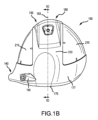
図1A~図1Fおよび図4~図8に示すように、第1の構成要素(300)は、クラウン(400)の一部を形成するリターン部(177)を有する打撃フェース(170)と、ホーゼル(140)と、ヒール端(160)の一部と、トウ端(150)の一部と、後縁(130)の一部と、リセス状リップ(450)(結合延長面とも呼ばれる)と、ソール(120)の一部と、を含むことができる。打撃フェースリターン部(177)は、打撃フェース(170)に対してほぼ垂直に配置され、打撃フェース(170)とは別の周囲から延びるリア延長部を備える。打撃フェースリターン部(177)は、ヒール端からトウ端方向に後方プロファイルを形成する。他の実施形態では、第1の構成要素(300)の後方プロファイルは、ヒール端(160)からトウ端(150)に向かって、直線状のプロファイル、正の放物線状のプロファイル、ベル形状のプロファイル、または打撃フェース(170)に対する任意の他のプロファイルで延びることができる。図2及び図3に示すように、第2の構成要素(200)は、クラウン(110)、ソール(120)、後縁(130)、及びリア切欠き(240)の少なくとも一部を含むことができる。 As shown in Figures 1A-1F and 4-8, the first component (300) can include a striking face (170) having a return portion (177) forming a portion of the crown (400), a hosel (140), a portion of the heel end (160), a portion of the toe end (150), a portion of the trailing edge (130), a recessed lip (450) (also referred to as a bond extension surface), and a portion of the sole (120). The striking face return portion (177) is disposed substantially perpendicular to the striking face (170) and includes a rear extension extending from a periphery separate from the striking face (170). The striking face return portion (177) forms a rearward profile in a heel-to-toe direction. In other embodiments, the rear profile of the first component (300) may extend from the heel end (160) toward the toe end (150) with a linear profile, a positive parabolic profile, a bell-shaped profile, or any other profile relative to the striking face (170). As shown in Figures 2 and 3, the second component (200) may include at least a portion of the crown (110), the sole (120), the trailing edge (130), and the rear notch (240).
第1の構成要素(300)は、第1の密度を有する第1の材料を含む。第1の材料は、金属材料を含む。第2の構成要素(200)は、第2の密度を含む第2の材料を含む。第2の構成要素(200)は、第2の構成要素質量を含む。 The first component (300) includes a first material having a first density. The first material includes a metallic material. The second component (200) includes a second material including a second density. The second component (200) includes a second component mass.
第1の構成要素(300)の第1の材料密度は、第2の構成要素(200)の第2の材料密度よりも大きい。第1の構成要素(300)の質量百分率は、ゴルフクラブヘッド(100)の質量の85%~96%の範囲であり得る。例えば、ゴルフクラブヘッドの質量の第1の構成要素百分率は、85%、86%、87%、88%、89%、90%、91%、92%、93%、94%、95%、または96%であってもよい。第2の構成要素(200)の質量百分率は、ゴルフクラブヘッド(100)の質量の4%から15%の範囲であり得る。第1の構成要素(300)は、リア延長部(500)の最後方位置に質量部(510)を有するソール部リア延長部(500)を含む。質量部(510)は、中空複数要素ゴルフクラブヘッド(100)の質量の20%~35%を構成することができる。ゴルフクラブヘッドの質量の大部分をゴルフクラブヘッドの最後方位置に配置することは、機能的に望ましい質量特性を提供する。例えば、質量部(510)の最後方位置は、ゴルフクラブヘッドのCGを下げることができ、これにより、打ち上げ特性が改善される。 The first material density of the first component (300) is greater than the second material density of the second component (200). The mass percentage of the first component (300) may be in the range of 85% to 96% of the mass of the golf club head (100). For example, the first component percentage of the mass of the golf club head may be 85%, 86%, 87%, 88%, 89%, 90%, 91%, 92%, 93%, 94%, 95%, or 96%. The mass percentage of the second component (200) may be in the range of 4% to 15% of the mass of the golf club head (100). The first component (300) includes a sole rear extension (500) having a mass portion (510) at the rearmost position of the rear extension (500). The mass (510) may comprise 20%-35% of the mass of the hollow multi-element golf club head (100). Locating the majority of the golf club head's mass at the rearmost position of the golf club head provides functionally desirable mass characteristics. For example, the rearmost position of the mass (510) may lower the CG of the golf club head, which may improve launch characteristics.
第1の構成要素(300)は、単一の部品として一体的に形成されてもよく、したがって、第1の構成要素は、単一の材料を含む。あるいは、第1の構成要素(300)は、第1の構成要素(300)の残りの部分とは異なる材料(すなわち、第3の材料)を含む、別個に形成された打撃フェースインサートを備えてもよい。 The first component (300) may be integrally formed as a single piece, such that the first component comprises a single material. Alternatively, the first component (300) may include a separately formed striking face insert that comprises a different material (i.e., a third material) than the remainder of the first component (300).
第1の金属構成要素(300)は、第1の構成要素(300)の周りを包む非金属の第2の構成要素(200)に結合されて、中空ゴルフクラブヘッド(100)を形成する。第2の構成要素の後縁(230)は、第2の構成要素クラウン部(205)と第2の構成要素ソール部(212,214)とを、それらが第1の構成要素(300)の周りを包むように接続する。 The first metallic component (300) is joined to a non-metallic second component (200) that wraps around the first component (300) to form a hollow golf club head (100). The rear edge (230) of the second component connects the second component crown portion (205) and the second component sole portion (212, 214) as they wrap around the first component (300).
図1Fを参照すると、ゴルフクラブヘッド(100)は、一緒に結合されて中空ゴルフクラブヘッドを形成するように構成された第1の構成要素(300)および第2の構成要素(200)を含む。ここで、第1の構成要素はT字形であり、金属材料を含む。第1の構成要素(300)のソールは、ソール延長部の最後端に質量部材を有するリアソール延長部を有する。この構成は、組み立てられたゴルフクラブヘッドのCGを、低下させるとともに、CGを組み立てられたゴルフクラブヘッドの後方に向かって移動させる。 Referring to FIG. 1F, the golf club head (100) includes a first component (300) and a second component (200) configured to be joined together to form a hollow golf club head, where the first component is T-shaped and includes a metal material. The sole of the first component (300) has a rear sole extension with a mass member at the rearmost end of the sole extension. This configuration lowers the CG of the assembled golf club head and moves the CG toward the rear of the assembled golf club head.
図1Eおよび図4を参照すると、第1の構成要素(300)は、ホーゼル軸(199)を画定するホーゼル穴(145)と、打撃フェース中心(175)と、打撃フェースクラウン部(420)と、打撃フェースリターンクラウン部幅(405)を有する打撃フェースリターンクラウン部(400)と、第1の構成要素後縁(440)と、を備える。いくつかの実施形態は、第1の構成要素のクラウン部タービュレータトウ部(432)および第1の構成要素のクラウン部タービュレータヒール部(434)を有する第1の構成要素クラウン部タービュレータ(430)をさらに備えることができる。 Referring to FIG. 1E and FIG. 4, the first component (300) comprises a hosel bore (145) defining a hosel axis (199), a striking face center (175), a striking face crown (420), a striking face return crown (400) having a striking face return crown width (405), and a first component trailing edge (440). Some embodiments may further comprise a first component crown turbulator (430) having a first component crown turbulator toe (432) and a first component crown turbulator heel (434).
第1の構成要素は、第2の構成要素の一部と重なり、一緒になってゴルフクラブヘッドを形成するように構成されたリセス状リップ(結合延長面とも呼ばれる)を含むことができる。第1の構成要素(300)は、第1の構成要素クラウン部リップ(455)と第1の構成要素タブ(457)とを有する第1の構成要素周囲縁部(462)に接する第1の構成要素リップ(450)を含むことができる。第1の構成要素タブ(457)、および第2の構成要素内の整合溝は、組立中に第1の構成要素(300)を第2の構成要素(200)に整列させ、また、第1の構成要素(300)と第2の構成要素(200)との間の横方向の移動を防止するための機械的支持を加える。 The first component may include a recessed lip (also called a bond extension surface) configured to overlap a portion of the second component and together form a golf club head. The first component (300) may include a first component lip (450) that abuts a first component peripheral edge (462) having a first component crown lip (455) and a first component tab (457). The first component tab (457) and the alignment groove in the second component align the first component (300) to the second component (200) during assembly and also add mechanical support to prevent lateral movement between the first component (300) and the second component (200).
第1の構成要素リップは、第2の構成要素の重なり合うリップと、2つの構成要素を互いに固定する任意の接着剤との合計厚さに適合するように、ゴルフクラブヘッドの外面から窪んでいる。図5を参照すると、第1の構成要素(300)は、第1の構成要素リップリセス状オフセット(459)と、第1の構成要素ソール部リップ(460)と、第1の構成要素ソール部リア延長部(500)と、質量部内部前方端部(502)を有する第1の構成要素ソール部リア延長質量部(510)と、1つまたは複数の質量部内部リブ(520)と、ねじ付き締結具受容ボス(542)および着脱可能ウェイトリセス内部前方端部(544)を有する着脱可能ウェイトリセス(540)とを備える。図1Fも参照すると、第1の構成要素リップ(455)は、第1の構成要素(300)が第2の構成要素(200)に結合されてゴルフクラブ(100)を形成するときに、第2の構成要素(200)の一部によって覆われるように構成される。第1の構成要素(300)は、好ましくは、第1の構成要素と第2の構成要素との重なり合う表面の間に配置された接着剤を用いて、第2の構成要素(200)に結合されてもよい。 The first component lip is recessed from the outer surface of the golf club head to accommodate the combined thickness of the overlapping lip of the second component and any adhesive that secures the two components together. Referring to FIG. 5, the first component (300) includes a first component lip recessed offset (459), a first component sole lip (460), a first component sole rear extension (500), a first component sole rear extension mass (510) having a mass inner forward end (502), one or more mass inner ribs (520), and a removable weight recess (540) having a threaded fastener receiving boss (542) and a removable weight recess inner forward end (544). Referring also to FIG. 1F, the first component lip (455) is configured to be covered by a portion of the second component (200) when the first component (300) is bonded to the second component (200) to form the golf club (100). The first component (300) may be bonded to the second component (200) preferably with an adhesive disposed between the overlapping surfaces of the first and second components.
図7を参照すると、第1の構成要素のリップは幅(730)を有し、これは0.125インチから0.275インチの範囲とすることができる。例えば、第1の構成要素のリップ幅(730)は、0.125インチ、0.150インチ、0.175インチ、0.200インチ、0.022インチ、0.225インチ、0.250インチ、または0.275インチとすることができる。 Referring to FIG. 7, the lip of the first component has a width (730) that can range from 0.125 inches to 0.275 inches. For example, the lip width (730) of the first component can be 0.125 inches, 0.150 inches, 0.175 inches, 0.200 inches, 0.022 inches, 0.225 inches, 0.250 inches, or 0.275 inches.
第1の構成要素リセス状オフセット(459)は、第1の構成要素(300)の外面からゴルフクラブヘッドの内部に向かう、リップ(455)のオフセット距離である。リセス状オフセット(459)は、ゴルフクラブヘッド(100)の内部に向かって0.060インチから0.160インチの範囲とすることができる。他の実施形態では、リセス状オフセット(459)は、0.060インチから0.150インチ、0.060インチから0.140インチ、0.080インチから0.160インチ、0.090インチから0.150インチ、または0.090インチから0.160インチの範囲とすることができる。例えば、リセス状オフセット(459)は、0.060インチ、0.070インチ、0.080インチ、0.090インチ、0.100インチ、0.110インチ、0.120インチ、0.130インチ、0.140インチ、0.150インチ、または0.160インチとすることができる。 The first component recessed offset (459) is the offset distance of the lip (455) from the exterior surface of the first component (300) toward the interior of the golf club head. The recessed offset (459) may range from 0.060 inches to 0.160 inches toward the interior of the golf club head (100). In other embodiments, the recessed offset (459) may range from 0.060 inches to 0.150 inches, 0.060 inches to 0.140 inches, 0.080 inches to 0.160 inches, 0.090 inches to 0.150 inches, or 0.090 inches to 0.160 inches. For example, the recessed offset (459) can be 0.060 inches, 0.070 inches, 0.080 inches, 0.090 inches, 0.100 inches, 0.110 inches, 0.120 inches, 0.130 inches, 0.140 inches, 0.150 inches, or 0.160 inches.
第1の構成要素リップ(450)は、厚さを含むことができる。第1の構成要素リップ(450)の厚さは、0.007インチから0.030インチの範囲とすることができる。いくつかの実施形態では、第1の構成要素リップ(450)の厚さは、約0.007インチから0.009インチ、0.009インチから0.011インチ、0.011インチから0.013インチ、0.013インチから0.015インチ、0.015インチから0.017インチ、0.017インチから0.019インチ、0.019インチから0.021インチ、0.021インチから0.023インチ、0.023インチから0.025インチ、0.025インチから0.027インチ、または0.027インチから0.030インチとすることができる。 The first component lip (450) can include a thickness. The thickness of the first component lip (450) can range from 0.007 inches to 0.030 inches. In some embodiments, the thickness of the first component lip (450) can be about 0.007 inches to 0.009 inches, 0.009 inches to 0.011 inches, 0.011 inches to 0.013 inches, 0.013 inches to 0.015 inches, 0.015 inches to 0.017 inches, 0.017 inches to 0.019 inches, 0.019 inches to 0.021 inches, 0.021 inches to 0.023 inches, 0.023 inches to 0.025 inches, 0.025 inches to 0.027 inches, or 0.027 inches to 0.030 inches.
さらに図5を参照すると、第1の構成要素は、ソールにリア延長部を有し、これにより、組み立てられたゴルフクラブヘッドの質量の大部分を、組み立てられたゴルフクラブのソールまで低下させ、そして後方に向かって移動させることができる。リア延長部(500)は、打撃フェースリターンから延び、打撃フェースリターンと一体であり、インパクト応力がソールの後部までずっと伝播することを可能にし、ゴルフクラブヘッドにおけるインパクト応力の分布のバランスをとるのに役立つ。 Still referring to FIG. 5, the first component has a rear extension at the sole that allows most of the mass of the assembled golf club head to be moved down and toward the rear of the sole of the assembled golf club. The rear extension (500) extends from and is integral with the striking face return, allowing impact stresses to propagate all the way to the rear of the sole and helping to balance the distribution of impact stresses in the golf club head.
さらに図5を参照すると、第1の構成要素リップ(450)は、第1の構成要素クラウン部リップ(455)と、第1の構成要素ソール部リップ(460)と、を含む。第1の構成要素リップ(450)は、他の部分を有してもよい。 With further reference to FIG. 5, the first component lip (450) includes a first component crown lip (455) and a first component sole lip (460). The first component lip (450) may have other portions.
図6を参照すると、接地面(105)に平行で打撃フェース中心(175)と交差する平面(610)は、図7に示す第1の構成要素(300)の下部の図を画定する。図7及び図8を参照すると、リア延長部(500)は、打撃フェースリターンソール部(810)の後方周囲からゴルフクラブヘッド(100)のリア端(180)に向かって延びている。 With reference to FIG. 6, a plane (610) parallel to the ground surface (105) and intersecting the striking face center (175) defines a bottom view of the first component (300) shown in FIG. 7. With reference to FIGS. 7 and 8, the rear extension (500) extends from the rear periphery of the striking face return sole portion (810) toward the rear end (180) of the golf club head (100).
図7を参照すると、第1の構成要素(300)は、第1の構成要素ソール部ヒール延長部(710)と、第1の構成要素ソール部トウ延長部(720)と、第1の構成要素リップ幅(730)を有する第1の構成要素リップ(460)と、第1の構成要素後縁部(740)と、垂直リップ(750)と質量部後縁シェルフ(760)を有する第1の構成要素ソール部リア延長質量部(510)と、を備える。 Referring to FIG. 7, the first component (300) comprises a first component sole heel extension (710), a first component sole toe extension (720), a first component lip (460) having a first component lip width (730), a first component trailing edge (740), and a first component sole rear extension mass (510) having a vertical lip (750) and a mass trailing edge shelf (760).
リア延長部(510)は、延長部の最も後方の位置において、より大きな質量を有する。質量を最も後方の位置に配置することは、組み立てられたゴルフクラブヘッドの質量特性に大きく影響するように、リアソール部延長位置の操作を可能にする。図8を参照すると、第1の構成要素(300)は、第1の構成要素ソール部リア延長部長さ(505)と第1の構成要素ソール部リア延長幅(507)を有する第1の構成要素ソール部リア延長部(500)を含む。第1の構成要素(300)は、打撃フェースリターンソール部幅(815)を有する打撃フェースリターンソール部(810)と、第1の構成要素ソール部トウ延長部長さ(825)を有する第1の構成要素ソール部分トウ延長部(820)と、第1の構成要素ソール部ヒール延長部長さ(835)を有する第1の構成要素ソール部ヒール延長部(830)と、を含む。リア延長部長さ(505)は、打撃フェースリターン部(810)の後方周囲から、リア端(180)に向かって測定される。リターンソール部の幅(815)は、ロフト面(198)から後方に向けて、第1の構成要素周囲端(462)のソール部分である、打撃フェースリターン部の後方周囲まで測定される。リア延長部の長さ(505)とリターンソール部の幅(815)は共に、ロフト平面(198)からソール(120)に沿ってリア端(180)まで測定されたゴルフクラブヘッド(100)のソール全長を構成する。リア延長部の幅(507)は、リア延長部(500)の幅である。リア延長部の幅(507)は、第1の構成要素周囲端(462)のソール部分である打撃フェースリターンソール部(810)の後方周囲のヒールからトウ方向に測定される。リア延長部の幅(507)は、ゴルフクラブ(100)のソール(120)の全幅よりも小さい。リア延長部の幅(507)は、ソール(120)の全幅の25%から85%の範囲とすることができる。リア延長部の幅(507)は、ソール(120)の全幅の25%から85%の範囲とすることができる。 The rear extension (510) has a greater mass at the rearmost position of the extension. Placing the mass at the rearmost position allows for manipulation of the rear sole extension position to significantly affect the mass properties of the assembled golf club head. Referring to FIG. 8, the first component (300) includes a first component sole portion rear extension (500) having a first component sole portion rear extension length (505) and a first component sole portion rear extension width (507). The first component (300) includes a striking face return sole portion (810) having a striking face return sole portion width (815), a first component sole portion toe extension (820) having a first component sole portion toe extension length (825), and a first component sole portion heel extension (830) having a first component sole portion heel extension length (835). The rear extension length (505) is measured from the rear perimeter of the striking face return portion (810) toward the rear end (180). The return sole portion width (815) is measured rearwardly from the loft plane (198) to the rear perimeter of the striking face return portion, which is the sole portion of the first component perimeter edge (462). The rear extension length (505) and the return sole portion width (815) together constitute the overall sole length of the golf club head (100) measured from the loft plane (198) along the sole (120) to the rear end (180). The rear extension width (507) is the width of the rear extension (500). The rear extension width (507) is measured from the heel to the toe of the rear perimeter of the striking face return sole portion (810), which is the sole portion of the first component perimeter edge (462). The width (507) of the rear extension is less than the overall width of the sole (120) of the golf club (100). The width (507) of the rear extension may range from 25% to 85% of the overall width of the sole (120). The width (507) of the rear extension may range from 25% to 85% of the overall width of the sole (120).
リア延長部の幅(507)は、ソール(120)の全幅の25%から85%の範囲とすることができる。第1の構成要素ソール部リア延長部(500)は、トウ延長部(720)に対してトウ方向角度(850)を形成し、ヒール延長部(710)に対してヒール方向角度(855)を形成する。第1の構成要素(300)は、複数の着脱可能ウェイトリセスタブ(546)を有する着脱可能ウェイトリセス(540)をさらに備える。 The width (507) of the rear extension can range from 25% to 85% of the overall width of the sole (120). The first component sole rear extension (500) forms a toe angle (850) with the toe extension (720) and a heel angle (855) with the heel extension (710). The first component (300) further comprises a removable weight recess (540) having a plurality of removable weight recess tabs (546).
図5、7、および8を参照すると、打撃フェースリターン(177)は、打撃フェース(170)に対して基本的に垂直に、打撃フェース周囲から後方に延在する。打撃フェース(170)及び打撃フェースリターン(177)は、組み立てられたゴルフクラブヘッドの前方部分を構成する。打撃フェースリターン(177)は、打撃フェースリターンクラウン部幅(405)を有する打撃フェースリターンクラウン部(400)と、打撃フェースリターンソール部幅(815)を有する打撃フェースリターンソール部(810)と、を含む。打撃フェースリターンクラウン部(400)は、クラウン(110)のヒール端(160)からクラウン(110)のトウ端(150)までのクラウン(110)上にプロファイルを形成する後方周囲を備える。打撃フェース(170)からリア端(180)に向かって測定される打撃フェースリターンクラウン部分幅は、変化してもよい。打撃フェースリターンクラウン部の最大幅(405)は、トウ端(150)とヒール端(160)において小さく、トウ端(150)とヒール端(160)との間の中間領域において大きくてもよい。打撃リターンクラウン部の幅(405)は、少なくとも0.8インチ、少なくとも1.0インチ、少なくとも1.2インチ、または少なくとも1.4インチとすることができる。いくつかの実施態様において、打撃フェースリターンクラウン部の最大幅(405)は、1.0インチから1.5インチの範囲であり得る。例えば、打撃フェースリターンクラウン部の最大幅(405)は、1.0インチ、1.1インチ、1.2インチ、1.3インチ、1.4インチ、または1.5インチであってもよい。第2の構成要素のクラウン部の幅(405)は、米国特許出願第11/693,490、現在は米国特許第7,601,078号に記載されているようなクラウン部と同様とすることができる。 5, 7, and 8, the striking face return (177) extends rearwardly from the striking face perimeter essentially perpendicular to the striking face (170). The striking face (170) and striking face return (177) constitute a forward portion of the assembled golf club head. The striking face return (177) includes a striking face return crown portion (400) having a striking face return crown portion width (405) and a striking face return sole portion (810) having a striking face return sole portion width (815). The striking face return crown portion (400) includes a rear perimeter that forms a profile on the crown (110) from the heel end (160) of the crown (110) to the toe end (150) of the crown (110). The striking face return crown portion width measured from the striking face (170) toward the rear end (180) may vary. The maximum width (405) of the striking face return crown portion may be smaller at the toe end (150) and the heel end (160) and larger in an intermediate region between the toe end (150) and the heel end (160). The striking face return crown portion width (405) may be at least 0.8 inches, at least 1.0 inches, at least 1.2 inches, or at least 1.4 inches. In some implementations, the striking face return crown portion maximum width (405) may range from 1.0 inches to 1.5 inches. For example, the striking face return crown portion maximum width (405) may be 1.0 inches, 1.1 inches, 1.2 inches, 1.3 inches, 1.4 inches, or 1.5 inches. The second component crown portion width (405) may be similar to the crown portion as described in U.S. Patent Application Serial No. 11/693,490, now U.S. Patent No. 7,601,078.
リアソール延長部の位置を操作することは、組み立てられたゴルフクラブヘッドの質量特性を操作する手段を提供する。図4、図5、図7、および図8を参照すると、第1の構成要素のソール部は、打撃フェース付近の中心から、第1の構成要素のソール部のトウ端延長部(720)を形成するトウ端に向かって、第1の構成要素のソール部のヒール端延長部(710)を形成するヒール端に向かって、および第1の構成要素のソール部のリア延長部(500)を形成するリア端に向かって延びることができる。第1の構成要素ソール部トウ延長部(720)、第1の構成要素ソール部ヒール延長部(710)、および第1の構成要素ソール部リア延長部(500)は、「T」字形プロファイルを形成することができる。いくつかの実施形態では、トウ延長部は、YZ平面からトウ端部(150)に向かって1.50インチから2.00インチの範囲の第1の構成要素ソール部トウ端部延長部長さ(825)を有することができる。例えば、第1の構成要素ソール部トウ延長部(720)は、トウ端部(150)に向かって1.50インチ、1.60インチ、1.70インチ、1.80インチ、1.90インチ、または2.00インチの第1の構成要素ソール部トウ端延長部長さ(825)を有することができる。いくつかの実施形態では、第1の構成要素ソール部ヒール端延長部(710)は、YZ平面からヒール端(160)に向かって0.90インチから1.40インチの範囲の第1の構成要素ソール部ヒール延長部長さ(835)を有することができる。例えば、第1の構成要素ソール部ヒール端延長部(710)は、0.90インチ、1.10インチ、1.20インチ、1.30インチ、または1.40インチ延びることができる。第1の構成要素ソール部リア延長部(500)は、打撃フェースリターン部(177)から測定して2.30インチから2.90インチとすることができる。例えば、第1の構成要素ソール部リア延長部(500)は、打撃フェースリターン部(177)から、2.30インチ、2.40インチ、2.50インチ、2.60インチ、2.70インチ、2.80インチ、又は2.90インチの距離だけ延びることができる。 Manipulating the position of the rear sole extension provides a means of manipulating the mass properties of the assembled golf club head. With reference to FIGS. 4, 5, 7, and 8, the first component sole portion can extend from a center near the striking face toward a toe end forming a toe end extension (720) of the first component sole portion, toward a heel end forming a heel end extension (710) of the first component sole portion, and toward a rear end forming a rear extension (500) of the first component sole portion. The first component sole portion toe extension (720), the first component sole portion heel extension (710), and the first component sole portion rear extension (500) can form a "T" shaped profile. In some embodiments, the toe extension can have a first component sole portion toe end extension length (825) ranging from 1.50 inches to 2.00 inches from the YZ plane toward the toe end (150). For example, the first component sole toe extension (720) can have a first component sole toe extension length (825) of 1.50 inches, 1.60 inches, 1.70 inches, 1.80 inches, 1.90 inches, or 2.00 inches toward the toe end (150). In some embodiments, the first component sole heel extension (710) can have a first component sole heel extension length (835) ranging from 0.90 inches to 1.40 inches from the YZ plane toward the heel end (160). For example, the first component sole heel extension (710) can extend 0.90 inches, 1.10 inches, 1.20 inches, 1.30 inches, or 1.40 inches. The first component sole rear extension (500) can be 2.30 inches to 2.90 inches measured from the striking face return portion (177). For example, the first component sole rear extension (500) can extend from the striking face return portion (177) a distance of 2.30 inches, 2.40 inches, 2.50 inches, 2.60 inches, 2.70 inches, 2.80 inches, or 2.90 inches.
ゴルフクラブヘッド(100)のトウ端(150)またはヒール端(160)の近くに第1の構成要素ソール部リア延長部をシフトさせることは、組み立てられたゴルフクラブヘッドの質量特性を操作し、ボール飛行を変更する1つの手段を提供する。第1の構成要素(300)を製造するとき、第1の構成要素ソール部リア延長部(500)をゴルフクラブ(100)のトウ端(150)またはヒール端(160)に向かって移動させると、組み立てられたゴルフクラブヘッドの質量特性が変化する。第1の構成要素ソール部リア延長部(500)を第1の構成要素ソール部トウ端延長部(825)を減少させることによってトウ端部(150)に向かって移動させた場合、ゴルフクラブヘッド(100)の重心もトウ端(150)に向かって移動することになる。第1の構成要素ソール部リア延長部(500)をゴルフクラブヘッド(100)のヒール端(160)に向かって移動させた場合、ゴルフクラブヘッド(100)の重心もヒール端(160)に向かって移動する。 Shifting the first component sole rear extension closer to the toe end (150) or heel end (160) of the golf club head (100) provides one means of manipulating the mass properties of the assembled golf club head and altering the ball flight. When manufacturing the first component (300), moving the first component sole rear extension (500) toward the toe end (150) or heel end (160) of the golf club (100) changes the mass properties of the assembled golf club head. If the first component sole rear extension (500) is moved toward the toe end (150) by reducing the first component sole toe end extension (825), the center of gravity of the golf club head (100) will also move toward the toe end (150). When the first component sole rear extension (500) is moved toward the heel end (160) of the golf club head (100), the center of gravity of the golf club head (100) also moves toward the heel end (160).
第1の構成要素(300)のリターン部分は、リターン部分の外面と内面との間に延在する厚さを含むことができる。第1の構成要素の厚さは、0.015インチから0.040インチの範囲とすることができる。他の実施形態では、第1の構成要素の厚さは、0.010インチから0.040インチ、0.010インチから0.020インチ、0.015インチから0.025インチ、0.020インチから0.030インチ、0.025インチから0.035インチ、0.030インチから0.040インチ、0.040インチから0.10インチ、または0.10インチから0.25インチの範囲とすることができる。例えば、第1の構成要素の厚さは、0.010インチ、0.015インチ、0.020インチ、0.025インチ、0.030インチ、0.035インチ、または0.040インチとすることができる。第1の構成要素の厚さは、打撃フェース(170)、第1の構成要素クラウン部(420)、第1の構成要素ソール部(310)、第1の構成要素ソール部ヒール延長部(710)、第1の構成要素ソール部トウ延長部(720)、および第1の構成要素ソール部リア延長質量部(510)でさらに変化することができる。 The return portion of the first component (300) may include a thickness extending between the outer surface and the inner surface of the return portion. The thickness of the first component may range from 0.015 inches to 0.040 inches. In other embodiments, the thickness of the first component may range from 0.010 inches to 0.040 inches, 0.010 inches to 0.020 inches, 0.015 inches to 0.025 inches, 0.020 inches to 0.030 inches, 0.025 inches to 0.035 inches, 0.030 inches to 0.040 inches, 0.040 inches to 0.10 inches, or 0.10 inches to 0.25 inches. For example, the thickness of the first component may be 0.010 inches, 0.015 inches, 0.020 inches, 0.025 inches, 0.030 inches, 0.035 inches, or 0.040 inches. The thickness of the first component can further vary at the striking face (170), the first component crown portion (420), the first component sole portion (310), the first component sole portion heel extension (710), the first component sole portion toe extension (720), and the first component sole portion rear extension mass portion (510).
第1の構成要素(300)は、ゴルフクラブヘッド(100)の全表面積のうちの27インチ2から41インチ2の範囲の表面積を含む。いくつかの実施形態では、第1の構成要素(300)の表面積は、25インチ2から43インチ2、25インチ2から28インチ2、28インチ2から31インチ2、31インチ2から34インチ2、34インチ2から37インチ2、37インチ2から40インチ2、または40インチ2から43インチ2の範囲とすることができる。例えば、25インチ2、27インチ2、29インチ2、31インチ2、33インチ2、35インチ2、37インチ2、39インチ2、41インチ2、43インチ2などである。 The first component (300) comprises a surface area ranging from 27 in to 41 in of the total surface area of the golf club head (100). In some embodiments, the surface area of the first component (300) can range from 25 in to 43 in , 25 in to 28 in, 28 in to 31 in, 31 in to 34 in , 34 in to 37 in, 37 in to 40 in , or 40 in to 43 in . For example, 25 in , 27 in , 29 in , 31 in , 33 in, 35 in , 37 in , 39 in , 41 in , 43 in , etc.
第1の構成要素(300)は、鋼、タングステン、アルミニウム、チタン、バナジウム、クロム、コバルト、ニッケル、他の金属、または金属合金などの材料を含むことができる。いくつかの実施態様において、第1の構成要素(300)は、Ti-8Al-1Mo-1V合金を含むことができる。ゴルフクラブヘッド(100)がドライバー型クラブヘッドである多くの実施形態では、第1の構成要素(300)はチタン材料を含むことができる。ゴルフクラブヘッド(100)がフェアウェイウッド型クラブヘッドである多くの実施形態では、第1の構成要素(300)は、鋼材料を含むことができる。 The first component (300) can include materials such as steel, tungsten, aluminum, titanium, vanadium, chromium, cobalt, nickel, other metals, or metal alloys. In some implementations, the first component (300) can include a Ti-8Al-1Mo-1V alloy. In many embodiments where the golf club head (100) is a driver-type club head, the first component (300) can include a titanium material. In many embodiments where the golf club head (100) is a fairway wood-type club head, the first component (300) can include a steel material.
多くの実施形態では、第1の構成要素(300)を鋳造することができる。他の実施形態において、第1の構成要素(300)は、鍛造、プレス、圧延、押し出し、機械加工、電鋳、3-D印刷、または任意の適切な形成技術であり得る。図15を参照すると、第1の構成要素(300)が鋳造される実施形態では、第1の構成要素(300)は、1つまたは複数のヒール端鋳造支持バー(1510)と、1つまたは複数のトウ端鋳造支持バー(1512)と、を含む複数の鋳造支持バーをさらに備えることができる。
1)第1の構成要素リアソール延長部
In many embodiments, the first component (300) can be cast. In other embodiments, the first component (300) can be forged, pressed, rolled, extruded, machined, electroformed, 3-D printed, or any suitable forming technique. With reference to FIG. 15, in embodiments in which the first component (300) is cast, the first component (300) can further comprise a plurality of cast support bars, including one or more heel end cast support bars (1510) and one or more toe end cast support bars (1512).
1) First Component Rear Sole Extension
上述したように、第1の構成要素は、打撃フェース及び打撃フェースリターンを含む。ゴルフクラブヘッドのこれらの部分は、ゴルフクラブがボールを打つとき、インパクト力を受けて配分する。リア延長部(500)は、第1の構成要素の残りの部分と一体に形成され、打撃フェースリターン部(810)のソール部から延びる。さらに、リア延長部(500)の質量は、打撃フェースの中心を外したインパクトによって引き起こされるトルク力に抵抗する。多くの実施形態では、第1の構成要素ソール部トウ端延長部(720)および第1の構成要素ソール部ヒール端延長部(710)は、打撃フェース(170)に対して平行にすることができ、前部から後部まで一定の幅を備える。他の実施形態では、トウ端延長部(720)およびヒール端延長部(710)は、トウ端(150)およびヒール端(160)に向かって幅を増加および/または減少させることができ、様々な幅を含む。いくつかの実施形態では、第1の構成要素ソール部トウ端延長部(720)およびヒール端延長部(710)は、1.0インチから1.5インチの範囲の幅を含むことができる。例えば、トウ端延長部(720)およびヒール端延長部(710)は、1.00インチ、1.10インチ、1.20インチ、1.30インチ、1.40インチ、または1.50インチとすることができる。 As mentioned above, the first component includes the striking face and the striking face return. These portions of the golf club head receive and distribute impact forces when the golf club strikes the ball. The rear extension (500) is integrally formed with the remainder of the first component and extends from the sole of the striking face return (810). Additionally, the mass of the rear extension (500) resists torque forces caused by an impact off-center of the striking face. In many embodiments, the first component sole toe extension (720) and the first component sole heel extension (710) can be parallel to the striking face (170) and have a constant width from front to rear. In other embodiments, the toe extension (720) and the heel extension (710) can increase and/or decrease in width toward the toe end (150) and the heel end (160) and include a variety of widths. In some embodiments, the first component sole portion toe end extension (720) and heel end extension (710) can include a width ranging from 1.0 inches to 1.5 inches. For example, the toe end extension (720) and heel end extension (710) can be 1.00 inches, 1.10 inches, 1.20 inches, 1.30 inches, 1.40 inches, or 1.50 inches.
多くの実施形態では、第1の構成要素ソール部リア延長部(500)は、打撃フェースリターンソール部(810)のリア境界からリア端(180)に向かって、幅が増加し、幅が減少し、および/または一艇の幅(507)を含むことができる。いくつかの実施形態では、リア延長部(500)は、1.0インチから3.5インチの範囲の幅(507)を含むことができる。例えば、リア延長部は、1.0インチ、1.25インチ、1.50インチ、1.75インチ、2.00インチ、2.25インチ、2.50インチ、2.75インチ、3.0インチ、3.25インチ、または3.50インチとすることができる。いくつかの実施形態では、リア延長部(500)は、前後方向に変化する幅を備える。具体的には、リア延長部(500)は、前方から後方への方向に増加する幅を含むことができる。これらの実施形態では、リア延長部(500)の幅は、打撃フェースリターンソール部(810)に隣接する最小値、クラブヘッドの後部に隣接する最大値を有する。クラブヘッドの後部に向かってリア延長部(500)の幅を広げると、リア延長部(500)が重量またはウェイトシステムを支持することができる。リア延長部(500)の幅を変化させ、その結果、最小幅が打撃フェースリターンソール部(810)に隣接するようにし、フェースリターン部に隣接する質量を減少させ、この節約された重量をクラブヘッドの周囲に再配分することを可能にする。他の実施形態では、リア延長部(500)は、前後方向に減少する幅を含むことができる。クラブヘッドの後部に向かってリア延長部の幅を狭くすることにより、リア延長部(500)に取り付けられた重量またはウェイトシステムのための追加の構造的支持を提供することができる。 In many embodiments, the first component sole portion rear extension (500) can include an increasing width, a decreasing width, and/or a width of one side (507) from the rear boundary of the striking face return sole portion (810) toward the rear end (180). In some embodiments, the rear extension (500) can include a width (507) ranging from 1.0 inches to 3.5 inches. For example, the rear extension can be 1.0 inches, 1.25 inches, 1.50 inches, 1.75 inches, 2.00 inches, 2.25 inches, 2.50 inches, 2.75 inches, 3.0 inches, 3.25 inches, or 3.50 inches. In some embodiments, the rear extension (500) includes a width that varies in the fore-aft direction. Specifically, the rear extension (500) can include a width that increases in the front-to-aft direction. In these embodiments, the width of the rear extension (500) has a minimum adjacent the striking face return sole portion (810) and a maximum adjacent the rear of the club head. Increasing the width of the rear extension (500) toward the rear of the club head allows the rear extension (500) to support a weight or weight system. Varying the width of the rear extension (500) so that the minimum width is adjacent the striking face return sole portion (810) reduces mass adjacent the face return portion and allows this saved weight to be redistributed around the periphery of the club head. In other embodiments, the rear extension (500) can include a decreasing width in the front-to-rear direction. Narrowing the width of the rear extension toward the rear of the club head can provide additional structural support for a weight or weight system attached to the rear extension (500).
図2に示すようないくつかの実施形態では、第1の構成要素ソール部リア延長部(500)は、打撃フェース(170)に対して垂直方向に延在し、トウ端(150)とヒール端(160)との間の中心に位置することができる。他の実施形態では、リア延長部(500)は、トウ端(150)により近い位置で、またはヒール端部(160)により近い位置で延びることができる。リア延長部(500)は、ヒール端(160)に向かって0.05インチから1.0インチだけオフセットすることができる。例えば、リア延長部(500)は、ヒール端(160)に向かって0.1インチ、0.2インチ、0.3インチ、0.4インチ、0.5インチ、0.6インチ、0.7インチ、0.8インチ、0.9インチ、または1.0インチだけオフセットすることができる。第1の構成要素ソール部リア延長部(500)は、トウ端部(150)に向かって0.05インチから1.0インチだけオフセットすることができる。例えば、リア延長部(500)は、トウ端部(160)に向かって0.1インチ、0.2インチ、0.3インチ、0.4インチ、0.5インチ、0.6インチ、0.7インチ、0.8インチ、0.9インチ、又は1.0インチだけオフセットすることができる。 In some embodiments, such as that shown in FIG. 2, the first component sole portion rear extension (500) may extend perpendicular to the striking face (170) and may be centered between the toe end (150) and the heel end (160). In other embodiments, the rear extension (500) may extend closer to the toe end (150) or closer to the heel end (160). The rear extension (500) may be offset by 0.05 inches to 1.0 inches toward the heel end (160). For example, the rear extension (500) may be offset by 0.1 inches, 0.2 inches, 0.3 inches, 0.4 inches, 0.5 inches, 0.6 inches, 0.7 inches, 0.8 inches, 0.9 inches, or 1.0 inches toward the heel end (160). The first component sole rear extension (500) can be offset toward the toe end (150) by 0.05 inches to 1.0 inches. For example, the rear extension (500) can be offset toward the toe end (160) by 0.1 inches, 0.2 inches, 0.3 inches, 0.4 inches, 0.5 inches, 0.6 inches, 0.7 inches, 0.8 inches, 0.9 inches, or 1.0 inches.
第1の構成要素ソール部リア延長部(500)がトウ端(150)に向かってオフセットされている場合、ゴルフクラブヘッド(100)の重心はトウ部(150)に向かって0.150インチまでオフセットされ得る。例えば、重心は、トウ端(150)に向かって0.010インチ、0.020インチ、0.030インチ、0.040インチ、0.050インチ、0.060インチ、0.070インチ、0.080インチ、0.090インチ、0.100インチ、0.110インチ、0.120インチ、0.130インチ、0.140インチ、又は0.150インチだけオフセットされ得る。第1の構成要素ソール部リア延長部(500)がヒール端(160)に向かってオフセットされている場合、ゴルフクラブヘッド(100)の重心は、0.150インチまでヒール端(160)に向かってオフセットされ得る。例えば、重心は、ヒール端(160)に向かって0.010インチ、0.020インチ、0.030インチ、0.040インチ、0.050インチ、0.060インチ、0.070インチ、0.080インチ、0.090インチ、0.100インチ、0.110インチ、0.120インチ、0.130インチ、0.140インチ、または0.150インチだけオフセットされ得る。 If the first component sole rear extension (500) is offset toward the toe end (150), the center of gravity of the golf club head (100) may be offset toward the toe end (150) by up to 0.150 inches. For example, the center of gravity may be offset toward the toe end (150) by 0.010 inches, 0.020 inches, 0.030 inches, 0.040 inches, 0.050 inches, 0.060 inches, 0.070 inches, 0.080 inches, 0.090 inches, 0.100 inches, 0.110 inches, 0.120 inches, 0.130 inches, 0.140 inches, or 0.150 inches. If the first component sole rear extension (500) is offset toward the heel end (160), the center of gravity of the golf club head (100) may be offset toward the heel end (160) by up to 0.150 inches. For example, the center of gravity may be offset toward the heel end (160) by 0.010 inches, 0.020 inches, 0.030 inches, 0.040 inches, 0.050 inches, 0.060 inches, 0.070 inches, 0.080 inches, 0.090 inches, 0.100 inches, 0.110 inches, 0.120 inches, 0.130 inches, 0.140 inches, or 0.150 inches.
ゴルフクラブヘッドの質量特性を操作する別の手段は、第1の構成要素打撃フェースに対してリアソール延長部の角度を変えることである。第1の構成要素ソール部リア延長部トウ方向角度(850)および第1の構成要素ソール部リア延長部ヒール方向角度(855)は、補角である(すなわち、2つの角度は、180度まで加算される)。一実施形態では、トウ方向角度(850)およびヒール方向角度(855)は、それぞれ90度であり、したがって、リア延長部(500)は、本質的に、打撃フェース(170)に対して垂直である。別の実施形態では、トウ方向角度(850)およびヒール方向角度(855)は、2つの角度が補角であり続ける限り、それぞれ、45度から135度の間で変化し得る。例えば、トウ方向角度(850)は100度にでき、一方、ヒール方向角度(855)は補助的な80度になる。この例では、質量部(510)は、ゴルフクラブヘッド(100)のヒール端(180)に向かって角度的にオフセットされている。トウ方向角度(850)およびヒール方向角度(855)の他の組み合わせは、110度と70度、120度と60度、130度と50度、または135度と45度であってもよい。ゴルフクラブヘッドの重心は、リア質量部(510)の位置に向かってオフセットされるであろう。例えば、重心は、ヒール端(160)に向かって0.010インチ、0.020インチ、0.030インチ、0.040インチ、0.050インチ、0.060インチ、0.070インチ、0.080インチ、0.090インチ、0.100インチ、0.110インチ、0.120インチ、0.130インチ、0.140インチ、または0.150インチだけオフセットされ得る。同様に、トウ方向の角度は減少し、ヒール方向の角度は増加する。例えば、トウ方向角度(850)とヒール方向角度の組み合わせは、80度と100度、70度と110度、60度と120度、50度と130度、または45度と135度であってもよい。例えば、重心は、トウ端(160)に向かって0.010インチ、0.020インチ、0.030インチ、0.040インチ、0.050インチ、0.060インチ、0.070インチ、0.080インチ、0.090インチ、0.100インチ、0.110インチ、0.120インチ、0.130インチ、0.140インチ、または0.150インチだけオフセットされてもよい。この角度オフセットは、ボール飛行特性に影響を与えるために、リア質量を後方でヒール方向部分または後方でトウ方向部分の方により多く配置することによってクラブヘッド重心をその方向に位置させることが望ましい場合がある。異なる実施形態における他の角度オフセットは、第1の構成要素ソール部リア延長トウ方向角度(850)および第1の構成要素ソール部リア延長ヒール方向角(855)を異なるように組み合わせることにより、異なるクラブヘッド重心位置および異なるボール飛行特性を生成することができる。
2)第1の構成要素のリアソール延長部の質量
Another means of manipulating the mass properties of the golf club head is to vary the angle of the rear sole extension relative to the first component striking face. The first component sole rear extension toe angle (850) and the first component sole rear extension heel angle (855) are supplementary angles (i.e., the two angles add up to 180 degrees). In one embodiment, the toe angle (850) and the heel angle (855) are each 90 degrees, so the rear extension (500) is essentially perpendicular to the striking face (170). In another embodiment, the toe angle (850) and the heel angle (855) can each vary between 45 degrees and 135 degrees, as long as the two angles remain supplementary angles. For example, the toe angle (850) can be 100 degrees, while the heel angle (855) is a complementary 80 degrees. In this example, the mass (510) is angularly offset toward the heel end (180) of the golf club head (100). Other combinations of toe angles (850) and heel angles (855) may be 110 degrees and 70 degrees, 120 degrees and 60 degrees, 130 degrees and 50 degrees, or 135 degrees and 45 degrees. The center of gravity of the golf club head will be offset toward the location of the rear mass (510). For example, the center of gravity may be offset toward the heel end (160) by 0.010 inches, 0.020 inches, 0.030 inches, 0.040 inches, 0.050 inches, 0.060 inches, 0.070 inches, 0.080 inches, 0.090 inches, 0.100 inches, 0.110 inches, 0.120 inches, 0.130 inches, 0.140 inches, or 0.150 inches. Similarly, the toe angle decreases and the heel angle increases. For example, the combination of toe angle (850) and heel angle may be 80 degrees and 100 degrees, 70 degrees and 110 degrees, 60 degrees and 120 degrees, 50 degrees and 130 degrees, or 45 degrees and 135 degrees. For example, the center of gravity may be offset toward the toe end (160) by 0.010 inches, 0.020 inches, 0.030 inches, 0.040 inches, 0.050 inches, 0.060 inches, 0.070 inches, 0.080 inches, 0.090 inches, 0.100 inches, 0.110 inches, 0.120 inches, 0.130 inches, 0.140 inches, or 0.150 inches. This angular offset may be desirable to position the club head center of gravity in that direction by placing more rear mass toward the rear heelward or rearward toeward to affect ball flight characteristics. Other angular offsets in different embodiments can produce different club head center of gravity locations and different ball flight characteristics by different combinations of first component sole portion rear extension toeward angle (850) and first component sole portion rear extension heelward angle (855).
2) Mass of the rear sole extension of the first component
上述のように、第1の構成要素は、組み立てられたゴルフクラブヘッドの質量の大部分を含む。リア延長部(500)は、ゴルフクラブの質量の一部がクラブヘッドの後部に向かってクラブヘッドのソール内に離れて配置されることを可能にする。リア延長部(500)は、ゴルフクラブヘッドの後部に質量部を含み、そこでの質量がゴルフクラブヘッドのCGおよびMOIにさらに影響を及ぼすことを可能にする。第1の構成要素のソール部リア延長部質量部(510)は、単独で、ゴルフクラブヘッド(100)の全質量の20%から35%を含むことができる。この質量をリア延長部(500)の最後部に配置することは、第1の構成要素(300)の製造中にゴルフクラブヘッド(100)の質量特性を制御するための重要な態様である。 As mentioned above, the first component comprises the majority of the mass of the assembled golf club head. The rear extension (500) allows a portion of the golf club's mass to be located away in the sole of the club head towards the rear of the club head. The rear extension (500) allows a mass portion at the rear of the golf club head to further affect the CG and MOI of the golf club head. The sole-rear extension mass portion (510) of the first component alone can comprise 20% to 35% of the total mass of the golf club head (100). Locating this mass at the rearmost portion of the rear extension (500) is an important aspect to control the mass properties of the golf club head (100) during the manufacture of the first component (300).
図9を参照すると、第1の構成要素のソール部リア延長部質量部(510)は、ねじ付き受容部(545)と、1つまたは複数のウェイトリセスタブ(546)と、ヒール側外部境界(910)とトウ側外部境界(915)と前方外部境界(918)とを有する質量部(510)と、を備える。 Referring to FIG. 9, the first component sole rear extension mass (510) includes a threaded receiver (545), one or more weight recess tabs (546), and a mass (510) having a heel outer boundary (910), a toe outer boundary (915), and a front outer boundary (918).
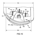
図10を参照すると、質量部(510)は、内部リブ幅(523)を有する複数の内部リブ(520)をさらに備える。複数の内部リブ(520)は、2つのリブ、3つのリブ、4つのリブ、5つのリブ、または5つ以上のリブを含むことができる。複数の内部リブ(520)は、リア延長部質量部の着脱可能ウェイトリセス(540)の内面と噛み合うか、またはそれに取り付けられる。内部リブ(520)は、質量部(510)における望ましくない振動を低減することができ、このことは、ゴルフクラブヘッド(100)の質量の大部分がゴルフクラブヘッドの後部まで配置されるので望ましい。質量部(510)は、垂直リップ高さ(1150)を有する垂直リップ(750)と、シェルフ長さ(1048)とシェルフ高さ(1044)とシェルフ幅(1046)とを有する質量部後縁シェルフ(1042)と、をさらに備える。シェルフ長さ(1048)は、リア延長部の幅(507)とほぼ同じであり、質量部(510)の幅が変化するにつれて変化する。 10, the mass (510) further comprises a plurality of internal ribs (520) having an internal rib width (523). The plurality of internal ribs (520) can include two ribs, three ribs, four ribs, five ribs, or more than four ribs. The plurality of internal ribs (520) mate with or are attached to an inner surface of the removable weight recess (540) of the rear extension mass. The internal ribs (520) can reduce undesirable vibrations in the mass (510), which is desirable since the majority of the mass of the golf club head (100) is located to the rear of the golf club head. The mass (510) further comprises a vertical lip (750) having a vertical lip height (1150) and a mass trailing edge shelf (1042) having a shelf length (1048), a shelf height (1044), and a shelf width (1046). The shelf length (1048) is approximately the same as the width (507) of the rear extension and changes as the width of the mass (510) changes.
シェルフ(1042)は、第1および第2の構成要素が結合されて組み立てられたゴルフクラブヘッドを形成するときに、第2の構成要素の一部のための合わせ面を提供する。質量部(510)は、内部前方境界(1050)と、垂直リップ長さ(1052)と、をさらに含む。 The shelf (1042) provides a mating surface for a portion of the second component when the first and second components are joined to form an assembled golf club head. The mass (510) further includes an inner forward boundary (1050) and a vertical lip length (1052).
図8を参照すると、リア部の質量体(510)の図は、YZ平面(800)によって二分される。図11を参照すると、質量部(510)は、内部長さ(1110)と、質量部の最大高さ(1112)と、垂直リップ高さ(1150)と、をさらに含む。内部リブは、リブ高さ(1120)と、リブ長さ(1122)と、をさらに備える。 Referring to FIG. 8, a view of the rear mass (510) is bisected by the YZ plane (800). Referring to FIG. 11, the mass (510) further includes an internal length (1110), a maximum mass height (1112), and a vertical lip height (1150). The internal rib further includes a rib height (1120) and a rib length (1122).
内部リブ幅(523)は、0.025インチから0.100インチの範囲とすることができる。例えば、内部リブ幅(523)は、0.025インチ、0.050インチ、0.075インチ、または0.100インチであってもよい。内部リブ高さ(1120)は、着脱可能ウェイトリセス深さ(1216)の25%から100%の範囲である。内部リブ長さ(1122)は、0.100インチから1.500インチの範囲とすることができる。例えば、内部リブ長さ(1122)は、0.100インチ、0.200インチ、0.300インチ、0.400インチ、0.500インチ、0.600インチ、0.700インチ、0.800インチ、0.900インチ、1.000インチ、1.100インチ、1.200インチ、1.300インチ、1.400インチ、または1.500インチであってもよい。 The internal rib width (523) may range from 0.025 inches to 0.100 inches. For example, the internal rib width (523) may be 0.025 inches, 0.050 inches, 0.075 inches, or 0.100 inches. The internal rib height (1120) ranges from 25% to 100% of the removable weight recess depth (1216). The internal rib length (1122) may range from 0.100 inches to 1.500 inches. For example, the internal rib length (1122) may be 0.100 inches, 0.200 inches, 0.300 inches, 0.400 inches, 0.500 inches, 0.600 inches, 0.700 inches, 0.800 inches, 0.900 inches, 1.000 inches, 1.100 inches, 1.200 inches, 1.300 inches, 1.400 inches, or 1.500 inches.
質量部(510)は、質量部垂直リップ(750)のほぼ上部に沿って位置する質量部の最大高さ(1112)を有する。質量部分(510)は、ヒール側外部境界(910)とトウ側外部境界(915)と前方外部境界(918)に近づくにつれて、厚さが減少する。質量部の最大高さ(1112)は、質量部(510)の最大厚さを含む。質量部分(510)の最大厚さは、0.40インチから0.70インチの範囲とすることができる。例えば、質量部(510)の最大厚さは、0.40インチ、0.50インチ、0.60インチ、または0.70インチであってもよい。
3)第1の構成要素の着脱可能ウェイトと埋め込みウェイト
The mass (510) has a maximum mass height (1112) located approximately along the top of the mass vertical lip (750). The mass (510) decreases in thickness as it approaches the heel outer boundary (910), the toe outer boundary (915), and the front outer boundary (918). The maximum mass height (1112) includes a maximum thickness of the mass (510). The maximum thickness of the mass (510) can range from 0.40 inches to 0.70 inches. For example, the maximum thickness of the mass (510) may be 0.40 inches, 0.50 inches, 0.60 inches, or 0.70 inches.
3) Removable and embedded weights of the first component
組み立てられたゴルフクラブヘッドの質量特性のさらなるコントロールを可能にするために、着脱可能ウェイトリセスと着脱可能ウェイトが設けられ、着脱可能ウェイトの質量は、組み立てられた時点でゴルフクラブヘッドの質量特性を微調整することができる。着脱可能ウェイトリセス(540)は、複数の着脱可能ウェイトリセスタブをさらに備える。複数の着脱可能ウェイトリセスタブは、2つのタブ、3つのタブ、4つのタブ、5つのタブ、または5つ以上のタブであってもよい。 To allow further control of the mass properties of the assembled golf club head, a removable weight recess and a removable weight are provided, the mass of which can be adjusted to fine-tune the mass properties of the golf club head once assembled. The removable weight recess (540) further comprises a plurality of removable weight recess tabs. The plurality of removable weight recess tabs may be two tabs, three tabs, four tabs, five tabs, or more than four tabs.
図12を参照すると、ゴルフクラブヘッドの最後部に配置される質量をさらに増加させることが望ましい。質量部(510)は、埋め込みウェイトリセス(1220)をさらに備える。したがって、埋め込みウェイトリセス(1220)、および第1の構成要素(300)の第1の材料の第1の密度よりも高い密度を有する埋め込みウェイト材料を含む埋め込みウェイト(1600)(埋め込みウェイトリセス(1220)に受容されるように構成される)を提供することができる。 Referring to FIG. 12, it is desirable to further increase the mass located at the rearmost portion of the golf club head. The mass portion (510) further comprises a recessed weight recess (1220). Thus, it is possible to provide a recessed weight recess (1220) and a recessed weight (1600) (configured to be received in the recessed weight recess (1220)) that includes a recessed weight material having a density greater than the first density of the first material of the first component (300).
図13を参照すると、着脱可能ウェイト(1300)は、鋼、タングステン、アルミニウム、チタン、バナジウム、クロム、コバルト、ニッケル、他の金属、金属合金、複合ポリマー材料、またはそれらの任意の組み合わせなどの材料を含むことができる。多くの実施形態では、ソールウェイトはタングステンとすることができる。着脱可能ウェイト(1300)は、質量を有する。 Referring to FIG. 13, the removable weight (1300) can include materials such as steel, tungsten, aluminum, titanium, vanadium, chromium, cobalt, nickel, other metals, metal alloys, composite polymeric materials, or any combination thereof. In many embodiments, the sole weight can be tungsten. The removable weight (1300) has a mass.
着脱可能ウェイト(1300)の質量は、1.0グラムから20.0グラムの範囲とすることができる。例えば、着脱可能ウェイト(1300)質量は、1.0グラム、1.5グラム、2.0グラム、3.0グラム、4.0グラム、5.0グラム、6.0グラム、7.0グラム、8.0グラム、9.0グラム、10.0グラム、11.0グラム、12.0グラム、13.0グラム、14.0グラム、15.0グラム、16.0グラム、17.0グラム、18.0グラム、19.0グラム、または20.0グラムであってもよい。 The mass of the removable weight (1300) can range from 1.0 grams to 20.0 grams. For example, the mass of the removable weight (1300) may be 1.0 grams, 1.5 grams, 2.0 grams, 3.0 grams, 4.0 grams, 5.0 grams, 6.0 grams, 7.0 grams, 8.0 grams, 9.0 grams, 10.0 grams, 11.0 grams, 12.0 grams, 13.0 grams, 14.0 grams, 15.0 grams, 16.0 grams, 17.0 grams, 18.0 grams, 19.0 grams, or 20.0 grams.
図8および図13を参照すると、着脱可能ウェイト(1300)は、着脱可能ウェイトリセス(540)内に受け入れられるように構成されている。着脱可能ウェイト(1300)は、着脱可能ウェイト(1300)のほぼ中央に貫通孔をさらに備える。貫通孔は、着脱可能ウェイトねじ付き締結具(1320)を受け入れるように構成され、ねじ付き締結具(1320)がねじ付き受容ボス(544)内に螺合可能に受け入れられて、着脱可能ウェイト(1300)を着脱可能ウェイトリセス(540)内に固定することを可能にする。 8 and 13, the removable weight (1300) is configured to be received within the removable weight recess (540). The removable weight (1300) further comprises a through hole approximately in the center of the removable weight (1300). The through hole is configured to receive a removable weight threaded fastener (1320) that is threadably received within the threaded receiving boss (544) to enable the removable weight (1300) to be secured within the removable weight recess (540).
図14を参照すると、着脱可能ウェイト(1300)は、厚さ(1430)と、複数の着脱可能ウェイトオフセット(1434)と、複数の着脱可能ウェイト側溝(1438)と、をさらに含む。複数の着脱可能ウェイトオフセット(1434)は、2つのオフセット、3つのオフセット、4つのオフセット、5つのオフセット、または5つより多いオフセットであってもよい。複数の着脱可能ウェイト側溝(1438)は、2つの溝、3つの溝、4つの溝、5つの溝、または5つ以上の溝であってもよい。オフセット(1434)は、着脱可能ウェイト(1300)が着脱可能ウェイトリセス(540)内に受け入れられたときに、着脱可能ウェイトリセス(540)の壁から、着脱可能ウェイト(1300)をわずかにオフセットさせるように構成される。着脱可能ウェイト側溝(1438)は、着脱可能ウェイト(1300)が着脱可能ウェイトリセス(540)内に受け入れられたときに、着脱可能ウェイトリセスタブを受け入れるように構成される。 14, the removable weight (1300) further includes a thickness (1430), a plurality of removable weight offsets (1434), and a plurality of removable weight grooves (1438). The plurality of removable weight offsets (1434) may be two offsets, three offsets, four offsets, five offsets, or more than five offsets. The plurality of removable weight grooves (1438) may be two grooves, three grooves, four grooves, five grooves, or more than five grooves. The offsets (1434) are configured to slightly offset the removable weight (1300) from the walls of the removable weight recess (540) when the removable weight (1300) is received within the removable weight recess (540). The removable weight groove (1438) is configured to receive the removable weight recess tab when the removable weight (1300) is received within the removable weight recess (540).
図16Aおよび16Bを参照すると、埋め込みウェイト(1600)は質量を有する。埋め込みウェイト(1600)の質量は、1.0グラムから20.0グラムの範囲とすることができる。例えば、埋め込みウェイト(1600)質量は、1.0g、2.0g、3.0g、4.0g、5.0g、6.0g、7.0g、8.0g、9.0g、10.0g、11.0g、12.0g、13.0g、14.0g、15.0g、16.0g、17.0g、18.0g、19.0g、または20.0gであってもよい。 Referring to Figures 16A and 16B, the embedded weight (1600) has a mass. The mass of the embedded weight (1600) can range from 1.0 grams to 20.0 grams. For example, the embedded weight (1600) mass can be 1.0g, 2.0g, 3.0g, 4.0g, 5.0g, 6.0g, 7.0g, 8.0g, 9.0g, 10.0g, 11.0g, 12.0g, 13.0g, 14.0g, 15.0g, 16.0g, 17.0g, 18.0g, 19.0g, or 20.0g.
埋め込みウェイト(1600)は、タングステン材料、タングステン合金材料、タングステン粒子が埋め込まれたポリマーマトリックス、または第1の材料密度より大きい密度を有する任意の他の適切な材料を含む。埋め込みウェイト(1600)は、埋め込みウェイトリセス(1220)内に嵌合し、埋め込みウェイトリセス内に恒久的に固定されるように構成される。埋め込みウェイト(1600)は、接着剤を使用して、スウェッジングまたは他の圧入方法によって、または適切な機械的取り付け手段を使用することによって、恒久的に固定されてもよい。
B)第2の構成要素
The embedded weight (1600) comprises a tungsten material, a tungsten alloy material, a polymer matrix with embedded tungsten particles, or any other suitable material having a density greater than the first material density. The embedded weight (1600) is configured to fit within the embedded weight recess (1220) and be permanently secured within the embedded weight recess. The embedded weight (1600) may be permanently secured using an adhesive, by swaging or other press-fit methods, or by using a suitable mechanical attachment means.
B) Second component
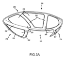
ゴルフクラブヘッド(100)は、共に結合されて中空ゴルフクラブヘッド(100)を形成するように構成された、第1の構成要素(300)および非金属の軽量の第2の構成要素(200)を備える。図1F及び図2を参照すると、第2の構成要素(200)は、第2の構成要素クラウン部(205)と、第2の構成要素ソール部ヒール部(214)と、第2の構成要素ソール部トウ部分(212)と、第2の構成要素周囲端部(220)と、第2の構成要素ソール部リア切欠き幅(242)及び第2の構成要素ソール部リア切欠き高さ(244)を有する第2の構成要素ソール部リア切欠き(240)と、第2の構成要素ソール部後縁(230)と、を含む。いくつかの実施形態では、図示されていないが、第2の構成要素は、クラウンの一部分のみを含むことができる。これらの実施形態では、ソール部リア切欠き(240)は、クラウン(205)を囲むことができる。 The golf club head (100) comprises a first component (300) and a non-metallic lightweight second component (200) configured to be joined together to form a hollow golf club head (100). With reference to FIG. 1F and FIG. 2, the second component (200) includes a second component crown portion (205), a second component sole heel portion (214), a second component sole toe portion (212), a second component peripheral end portion (220), a second component sole rear notch (240) having a second component sole rear notch width (242) and a second component sole rear notch height (244), and a second component sole rear edge (230). In some embodiments, not shown, the second component may include only a portion of the crown. In these embodiments, the sole rear cutout (240) can surround the crown (205).
図1~4に図示されるように、第2の構成要素クラウン部(205)は、後縁(130)の上を包み、第1の構成要素と相補的なソールの一部を一体的に形成する。第2の構成要素(200)によって形成された第2の構成要素のヒール及びトウソール部(214)(212)は、第1の構成要素の、トウ端延長部とリア端延長部との間に配置された三角形状、及びリア端延長部とヒール端延長部との間に配置された三角形状を含むことができる。他の実施形態では、第2の構成要素(200)によって形成されるソール部は、第1の構成要素(100)のソール部と相補的な、円形、正方形、楕円形、任意の他の多角形、または少なくとも1つの曲面を有する形状を含むことができる。第2の構成要素(200)は、さらなる接合を必要とせずに完全に一緒に形成された単一のモノリシック部品を含んでもよい。例えば、第2の構成要素(200)は、単一の材料を含む単一のモノリシック部品を射出成形することによって形成することができる。 As illustrated in Figures 1-4, the second component crown portion (205) wraps over the rear edge (130) and integrally forms a portion of the sole that is complementary to the first component. The heel and toe sole portion (214) (212) of the second component formed by the second component (200) can include a triangular shape disposed between the toe end extension and the rear end extension, and a triangular shape disposed between the rear end extension and the heel end extension of the first component. In other embodiments, the sole portion formed by the second component (200) can include a circle, a square, an oval, any other polygonal shape, or a shape having at least one curved surface, that is complementary to the sole portion of the first component (100). The second component (200) may include a single monolithic part that is completely formed together without the need for further joining. For example, the second component (200) can be formed by injection molding a single monolithic part that includes a single material.
あるいは、第2の構成要素(200)は、接着剤、音波溶接、融着、または複数の別々に形成された部分を形成する際に使用される材料に適切な他の恒久的な接合方法によってその後恒久的に接合される、複数の別々に形成された部分を備えてもよい。例えば、第2の構成要素のクラウン部(205)、トウ部(212)、およびヒール部(214)は、同じまたは異なる材料から別々に形成されてもよい。次に、第2の構成要素部分を接着接合して、完全な第2の構成要素(200)を形成することができる。後に接合される別個の部分のこのような形成は、双方向炭素繊維プリプレグ材料などの材料を使用する場合に有利であり得る。双方向炭素繊維プリプレグは、特定の小さな曲率に容易に適用することができず、所望の第2の構成要素(200)形状に到達するために単一のピースとして容易に形成することができない。このような材料を使用すると、別個のソール部(212)および(214)を形成する必要が生じ、これらのソール部は、後に接着剤または他の方法によって第2の構成要素(200)の残りの部分に接合される。 Alternatively, the second component (200) may comprise a number of separately formed portions that are subsequently permanently joined by adhesives, sonic welding, fusion, or other permanent joining methods appropriate to the materials used in forming the number of separately formed portions. For example, the crown portion (205), toe portion (212), and heel portion (214) of the second component may be separately formed from the same or different materials. The second component portions may then be adhesively bonded to form the complete second component (200). Such formation of separate portions that are subsequently joined may be advantageous when using materials such as bidirectional carbon fiber prepreg materials, which cannot be readily adapted to certain small curvatures and cannot be readily formed as a single piece to reach the desired second component (200) shape. The use of such materials may necessitate the formation of separate sole portions (212) and (214) that are subsequently bonded to the remainder of the second component (200) by adhesives or other methods.
ゴルフクラブヘッド(100)の第2の構成要素は、厚さを含むことができる。第2の構成要素の厚さは、0.045インチから0.500インチの範囲とすることができる。いくつかの実施形態では、第2の構成要素の厚さは、0.045インチから0.055インチ、0.050インチから0.060インチ、0.055インチから0.065インチ、0.060インチから0.070インチ、0.065インチから0.075インチ、0.070インチから0.080インチ、0.075インチから0.085インチ、0.080インチから0.090インチ、0.085インチから0.095インチ、0.090インチから0.100インチ、0.100インチから0.200インチ、0.200インチから0.300インチ、0.300インチから0.400インチ、または 0.400インチから0.500インチの範囲とすることができる。例えば、第2の構成要素の厚さは、0.008インチ、0.010インチ、0.015インチ、0.020インチ、0.025インチ、0.030インチ、0.035インチ、0.040インチ、0.045インチ、0.050インチ、0.055インチ、0.060インチ、又は0.065インチとすることができる。第2の構成要素の厚さは、クラウン、ソール、ヒール端、トウ端、および後縁からさらに変化させることができる。例えば、一実施形態では、第2の構成要素の厚さは、第2の構成要素のクラウン、ソール、ヒール端、トウ端、及び後縁にわたって異なる場合がある。いくつかの実施形態では、第2の構成要素は、内部リブをさらに含む。第2の構成要素の内部リブの厚さは、第2の構成要素の残りの部分と同じであってもよく、または第2の構成要素(200)の他の部分よりも0.010インチまで厚くてもよい。 The second component of the golf club head (100) may include a thickness. The thickness of the second component may range from 0.045 inches to 0.500 inches. In some embodiments, the thickness of the second component can range from 0.045 inches to 0.055 inches, 0.050 inches to 0.060 inches, 0.055 inches to 0.065 inches, 0.060 inches to 0.070 inches, 0.065 inches to 0.075 inches, 0.070 inches to 0.080 inches, 0.075 inches to 0.085 inches, 0.080 inches to 0.090 inches, 0.085 inches to 0.095 inches, 0.090 inches to 0.100 inches, 0.100 inches to 0.200 inches, 0.200 inches to 0.300 inches, 0.300 inches to 0.400 inches, or 0.400 inches to 0.500 inches. For example, the thickness of the second component can be 0.008 inches, 0.010 inches, 0.015 inches, 0.020 inches, 0.025 inches, 0.030 inches, 0.035 inches, 0.040 inches, 0.045 inches, 0.050 inches, 0.055 inches, 0.060 inches, or 0.065 inches. The thickness of the second component can further vary from the crown, sole, heel end, toe end, and trailing edge. For example, in one embodiment, the thickness of the second component can vary across the crown, sole, heel end, toe end, and trailing edge of the second component. In some embodiments, the second component further includes an internal rib. The thickness of the internal rib of the second component can be the same as the remainder of the second component or can be up to 0.010 inches thicker than other portions of the second component (200).
図3の実施形態のようないくつかの実施形態では、第2の構成要素(200)は、1つまたは複数のクラウン部薄肉セクション(255)および1つまたは複数のソール部薄肉セクション(257)を有する複数の第2の構成要素薄肉セクション(250)をさらに備える。第2の構成要素(200)は、1つまたは複数のクラウン部内部リブ(262)および1つまたは複数のソール部内部リブ(264)を有する複数の第2の構成要素内部リブ(260)をさらに備える。複数の内部リブ(260)は、2つのリブ、3つのリブ、4つのリブ、5つのリブ、または5つ以上のリブであってもよい。クラウン部(262)及びソール部(264)の内部リブは、第2の構成要素薄肉セクション(250)の間にある。クラウン部(262)及びソール部(264)の内部リブは、第2の構成要素(200)の最大厚さを含むことができる。いくつかの実施形態では、第2の構成要素の内部リブ(260)は、米国特許出願第15/076,511号(現在、米国特許第9,700,768号)に記載されているリブと同様とすることができる。第2の構成要素の内部リブ(260)は、ゴルフクラブヘッド(100)への応力を低減し、インパクト中の音を改善することができる。 In some embodiments, such as the embodiment of FIG. 3, the second component (200) further comprises a plurality of second component thin sections (250) having one or more crown thin sections (255) and one or more sole thin sections (257). The second component (200) further comprises a plurality of second component internal ribs (260) having one or more crown internal ribs (262) and one or more sole internal ribs (264). The plurality of internal ribs (260) may be two ribs, three ribs, four ribs, five ribs, or more than four ribs. The internal ribs of the crown (262) and sole (264) are between the second component thin sections (250). The internal ribs of the crown (262) and sole (264) may comprise the maximum thickness of the second component (200). In some embodiments, the internal ribs (260) of the second component can be similar to the ribs described in U.S. Patent Application Serial No. 15/076,511 (now U.S. Patent No. 9,700,768). The internal ribs (260) of the second component can reduce stress on the golf club head (100) and improve sound during impact.
複数の第2構成要素薄肉セクション(250)は、厚さを備える。複数の第2の構成要素薄肉セクション(250)の厚さは、0.008インチから0.035インチの範囲とすることができる。他の実施形態では、薄肉セクション(250)の厚さは、0.008インチから0.015インチ、0.010インチから0.020インチ、0.015インチから0.025インチ、0.020インチから0.030インチ、または0.025インチから0.035インチの範囲とすることができる。例えば、薄肉セクション(250)の厚さは、0.008インチ、0.010インチ、0.015インチ、0.020インチ、0.025インチ、0.030インチ、または0.035インチとすることができる。いくつかの実施形態では、第2の構成要素は、内部リブおよび薄肉セクションを欠いている。 The plurality of second component thinned sections (250) have a thickness. The thickness of the plurality of second component thinned sections (250) can range from 0.008 inches to 0.035 inches. In other embodiments, the thickness of the thinned sections (250) can range from 0.008 inches to 0.015 inches, 0.010 inches to 0.020 inches, 0.015 inches to 0.025 inches, 0.020 inches to 0.030 inches, or 0.025 inches to 0.035 inches. For example, the thickness of the thinned sections (250) can be 0.008 inches, 0.010 inches, 0.015 inches, 0.020 inches, 0.025 inches, 0.030 inches, or 0.035 inches. In some embodiments, the second component lacks internal ribs and thinned sections.
第2の構成要素は、ゴルフクラブヘッド(100)の全質量の質量百分率を含む。第2の構成要素の質量百分率は、ゴルフクラブヘッド(100)の全質量の4%から15%の範囲であってもよく、または約10グラムから25グラムであってもよい。他の実施形態では、第2の構成要素の質量百分率は、4%から15%の範囲であり得る。例えば、第2の構成要素の質量百分率は、ゴルフクラブヘッド(100)の全質量の4%、5%、6%、7%、8%、9%、10%、11%、12%、13%、14%、または15%であってもよい。 The second component comprises a mass percentage of the total mass of the golf club head (100). The mass percentage of the second component may range from 4% to 15% of the total mass of the golf club head (100), or may be approximately 10 grams to 25 grams. In other embodiments, the mass percentage of the second component may range from 4% to 15%. For example, the mass percentage of the second component may be 4%, 5%, 6%, 7%, 8%, 9%, 10%, 11%, 12%, 13%, 14%, or 15% of the total mass of the golf club head (100).
第2の構成要素は、17インチ2から25インチ2の範囲の外面面積を含む。いくつかの実施形態では、第2の構成要素の表面積は、15インチ2から27インチ2、15インチ2から18インチ2、18インチ2から21インチ2、21インチ2から25インチ2までの範囲であり得る。例えば、第2の構成要素の表面積は、15インチ2、17インチ2、19インチ2、21インチ2、23インチ2、25インチ2とすることができる。
1)第2の構成要素材料
The second component includes an exterior surface area ranging from 17 in2 to 25 in2 . In some embodiments, the surface area of the second component can range from 15 in2 to 27 in2 , 15 in2 to 18 in2, 18 in2 to 21 in2 , or 21 in2 to 25 in2 . For example, the surface area of the second component can be 15 in2 , 17 in2 , 19 in2 , 21 in2 , 23 in2 , or 25 in2.
1) Second Component Material
第2の構成要素(200)は、第1の構成要素の材料よりも密度の低い材料を含む。いくつかの実施形態では、第2の構成要素は、ポリマー樹脂および強化繊維から形成された複合体を含むことができる。ポリマー樹脂は、熱硬化性樹脂または熱可塑性樹脂を含むことができる。より具体的には、熱可塑性樹脂を有する実施形態では、樹脂は、熱可塑性ポリウレタン(TPU)または熱可塑性エラストマー(TPE)を含むことができる。例えば、樹脂は、ポリフェニレンスルフィド(PPS)、ポリエーテルエーテルケトン(PEEK)、ポリイミド、PA6またはPA66などのポリアミド、ポリアミドイミド、ポリフェニレンスルフィド(PPS)、ポリカーボネート、エンジニアリングポリウレタン、および/または他の同様の材料を含むことができる。強化繊維は、炭素繊維(またはチョップド炭素繊維)、ガラス繊維(またはチョップドガラス繊維)、グラファイト繊維(またはチョップドグラファイト繊維)、または任意の他の適切な充填材料を含むことができる。他の実施形態では、第2の構成要素複合材料は、加重用のビーズ(例えば、ガラスビーズ、金属ビーズ)または粉末(例えば、タングステン粉末)を含むことができる。他の実施形態では、複合材料は、強度、耐久性、および/または重量を加える任意の補強充填剤を含むことができる。 The second component (200) comprises a material having a lower density than the material of the first component. In some embodiments, the second component may comprise a composite formed from a polymer resin and reinforcing fibers. The polymer resin may comprise a thermosetting resin or a thermoplastic resin. More specifically, in embodiments having a thermoplastic resin, the resin may comprise a thermoplastic polyurethane (TPU) or a thermoplastic elastomer (TPE). For example, the resin may comprise polyphenylene sulfide (PPS), polyetheretherketone (PEEK), polyimide, polyamide such as PA6 or PA66, polyamideimide, polyphenylene sulfide (PPS), polycarbonate, engineering polyurethane, and/or other similar materials. The reinforcing fibers may comprise carbon fiber (or chopped carbon fiber), glass fiber (or chopped glass fiber), graphite fiber (or chopped graphite fiber), or any other suitable filler material. In other embodiments, the second component composite material may comprise weighting beads (e.g., glass beads, metal beads) or powders (e.g., tungsten powder). In other embodiments, the composite material can include any reinforcing fillers that add strength, durability, and/or weight.
ポリマー樹脂は、好ましくは、設計に重量節約の利益を提供しながら、典型的な使用に耐えるのに十分に高い材料強度および/または強度/重量比特性を有する1つ以上のポリマーを組み込むべきである。具体的には、ゴルフクラブヘッドの総重量に実質的に寄与せずに、打撃フェースとゴルフボールとの間のインパクト中に与えられる応力に効率的に耐えることが、設計および材料にとって重要である。一般に、ポリマーは、約60MPa(ニート)を超える降伏点引張強度を特徴とすることができる。ポリマー樹脂が強化繊維と組み合わされる場合、得られる複合材料は、約110MPaを超える、約180MPaを超える、約220MPaを超える、約260MPaを超える、約280MPaを超える、または約290MPaを超える降伏引張強度を有することができる。いくつかの実施形態では、適切な複合材料は、約60MPa~約350MPaの降伏点引張強度を有してもよい。 The polymer resin should preferably incorporate one or more polymers that have sufficiently high material strength and/or strength/weight ratio properties to withstand typical use while providing weight saving benefits to the design. Specifically, it is important for the design and materials to efficiently withstand the stresses imposed during impact between the striking face and the golf ball without contributing substantially to the overall weight of the golf club head. Generally, the polymer can be characterized by a yield tensile strength of greater than about 60 MPa (neat). When the polymer resin is combined with reinforcing fibers, the resulting composite material can have a yield tensile strength of greater than about 110 MPa, greater than about 180 MPa, greater than about 220 MPa, greater than about 260 MPa, greater than about 280 MPa, or greater than about 290 MPa. In some embodiments, suitable composite materials may have a yield tensile strength of about 60 MPa to about 350 MPa.
いくつかの実施形態では、強化繊維は、複数の分散不連続繊維(すなわち、「チョップド繊維」)を含む。いくつかの実施形態では、強化繊維は、約3mmから14mmの設計繊維長を有する不連続「長繊維」を含む。例えば、いくつかの実施形態では、繊維長は、成形プロセスの前に約12.7mm(0.5インチ)である。別の実施形態では、強化繊維は、約0.01mmから3mmの設計繊維長を有する不連続「短繊維」を含む。いずれの場合(短繊維または長繊維)においても、所与の長さは、予め混合された長さであり、成形プロセス中の破損のために、いくつかの繊維は、実際には、最終構成要素において記載された範囲よりも短くなり得ることに留意されたい。いくつかの構成では、不連続な細断繊維は、約10を超える、またはより好ましくは約50を超える、約1500未満のアスペクト比(例えば、繊維の長さ/直径)によって特徴付けられてもよい。使用される不連続チョップド繊維のタイプにかかわらず、特定の構成では、複合材料は、約0.01mmから約14mmの繊維長を有してもよい。 In some embodiments, the reinforcing fibers include a plurality of dispersed discontinuous fibers (i.e., "chopped fibers"). In some embodiments, the reinforcing fibers include discontinuous "long fibers" having a design fiber length of about 3 mm to 14 mm. For example, in some embodiments, the fiber length is about 12.7 mm (0.5 inches) prior to the molding process. In another embodiment, the reinforcing fibers include discontinuous "short fibers" having a design fiber length of about 0.01 mm to 3 mm. Note that in either case (short or long fibers), the given length is a premixed length, and that due to breakage during the molding process, some fibers may actually be shorter than the stated range in the final component. In some configurations, the discontinuous chopped fibers may be characterized by an aspect ratio (e.g., fiber length/diameter) of greater than about 10, or more preferably greater than about 50, and less than about 1500. Regardless of the type of discontinuous chopped fiber used, in certain configurations, the composite may have a fiber length of about 0.01 mm to about 14 mm.
複合材料は、約40重量%から約90重量%、または約55重量%から約70重量%のポリマー樹脂含有量を有してもよい。第2の構成要素の複合材料は、約10重量%から約60重量%の繊維含有量を有することができる。いくつかの実施形態では、複合材料は、約20重量%から約50重量%、30重量%から40重量%の繊維含有量を有する。いくつかの実施形態では、複合材料は、約10重量%から約15重量%、約15重量%から約20重量%、約20重量%から約25重量%、約25重量%から約30重量%、約30重量%から約35重量%、約35重量%から約40重量%、約40重量%から約45重量%、約45重量%から約50重量%、約50重量%から約55重量%、または約55重量%から約60重量%の繊維含有量を有する。 The composite material may have a polymer resin content of about 40% to about 90% by weight, or about 55% to about 70% by weight. The composite material of the second component may have a fiber content of about 10% to about 60% by weight. In some embodiments, the composite material has a fiber content of about 20% to about 50% by weight, 30% to 40% by weight. In some embodiments, the composite material has a fiber content of about 10% to about 15% by weight, about 15% to about 20% by weight, about 20% to about 25% by weight, about 25% to about 30% by weight, about 30% to about 35% by weight, about 35% to about 40% by weight, about 40% to about 45% by weight, about 45% to about 50% by weight, about 50% to about 55% by weight, or about 55% to about 60% by weight.
第2の構成要素を形成する複合材料の密度は、約1.15g/ccから約2.02g/ccの範囲とすることができる。いくつかの実施形態では、複合材料密度は、約1.30g/ccから約1.40g/cc、または約1.40g/ccから約1.45g/ccの範囲である。複合材料は、約210℃から約280℃の融点を有することができる。いくつかの実施形態では、複合材料は、約250℃から約270℃の融点を有することができる。 The density of the composite material forming the second component can range from about 1.15 g/cc to about 2.02 g/cc. In some embodiments, the composite density ranges from about 1.30 g/cc to about 1.40 g/cc, or from about 1.40 g/cc to about 1.45 g/cc. The composite material can have a melting point of about 210°C to about 280°C. In some embodiments, the composite material can have a melting point of about 250°C to about 270°C.
いくつかの実施形態では、複合材料は、長繊維強化TPUを含む。長繊維TPUは、約40重量%の長炭素繊維を含むことができる。長繊維TPUは、短炭素繊維化合物の弾性率よりも大きい高い弾性率を示すことができる。長繊維TPUは、高温に耐えることができ、高温環境で使用および/または保管されるゴルフクラブヘッドでの使用に適したものにする。長繊維TPUは、さらに高い靭性を示し、従来の金属部品の代替品としての役割を果たすことができる。いくつかの実施態様において、長繊維TPUは、約26,000MPaから約30,000MPa、または約27,000MPaから約29,000MPaの間の引張弾性率を含む。いくつかの実施態様において、長繊維TPUは、約21,000MPaから約26,000MPa、または約22,000MPaから25,000MPaの間の曲げ弾性率を含む。長繊維TPU材料は、約0.5%から約2.5%の引張伸び(破断点)を示すことができる。いくつかの実施形態では、複合TPU材料の引張伸びは、約1.0%から約2.0%、約1.2%から約1.4%、約1.4%から約1.6%、約1.6%から約1.8%、約1.8%から約2.0%とすることができる。 In some embodiments, the composite material includes a long fiber reinforced TPU. The long fiber TPU can include about 40% by weight of long carbon fiber. The long fiber TPU can exhibit a high modulus of elasticity that is greater than that of short carbon fiber compounds. The long fiber TPU can withstand high temperatures, making it suitable for use in golf club heads that are used and/or stored in high temperature environments. The long fiber TPU can also exhibit high toughness and can serve as a replacement for traditional metal components. In some embodiments, the long fiber TPU includes a tensile modulus of about 26,000 MPa to about 30,000 MPa, or about 27,000 MPa to about 29,000 MPa. In some embodiments, the long fiber TPU includes a flexural modulus of about 21,000 MPa to about 26,000 MPa, or about 22,000 MPa to 25,000 MPa. The long fiber TPU material can exhibit a tensile elongation (at break) of about 0.5% to about 2.5%. In some embodiments, the tensile elongation of the composite TPU material can be about 1.0% to about 2.0%, about 1.2% to about 1.4%, about 1.4% to about 1.6%, about 1.6% to about 1.8%, or about 1.8% to about 2.0%.
強度および重量は、複合材料について考慮される2つの主要な特性であるが、適切な複合材料はまた、二次的な利点を示し得る。例えば、PPSおよびPEEKは、本設計の強度および重量要件を満たす2つの例示的な熱可塑性ポリマーである。しかしながら、多くの他のポリマーとは異なり、PPSまたはPEEKの使用は、それらの独特の音響特性のためにさらに有利である。具体的には、多くの状況において、PPS及びPEEKは、インパクトを受けたときに、一般的に金属的に鳴る音響応答を発する。したがって、PPSまたはPEEKポリマーを使用することによって、本設計は、インパクト時の望ましい金属クラブヘッド音を損なうことはなく、ポリマーの強度/重量の利点を活用することができる。 While strength and weight are the two primary properties considered for composite materials, suitable composite materials may also exhibit secondary benefits. For example, PPS and PEEK are two exemplary thermoplastic polymers that meet the strength and weight requirements of the present design. However, unlike many other polymers, the use of PPS or PEEK is further advantageous due to their unique acoustic properties. Specifically, in many situations, PPS and PEEK emit a generally metallic ringing acoustic response upon impact. Thus, by using PPS or PEEK polymers, the present design can leverage the strength/weight benefits of polymers without compromising the desirable metal clubhead sound upon impact.
多くの実施形態では、ゴルフクラブヘッド(100)の第2の構成要素(200)は、射出成形することができる。第2の構成要素(200)は、ポリマー樹脂と強化繊維の両方を含む1つの複合材料から射出成形することができる。強化繊維は、第2の構成要素を成形する前に樹脂内に埋め込むことができる。樹脂および繊維の両方を含む複合材料は、ペレット形態で提供することができる。ペレットは、溶融され、空の金型に注入されて、第2の構成要素を形成することができる。他の実施形態では、第2の構成要素は、押出成形、射出ブロー成形、3-D印刷、または任意の他の適切な成形手段とすることができる。 In many embodiments, the second component (200) of the golf club head (100) can be injection molded. The second component (200) can be injection molded from a composite material that includes both polymer resin and reinforcing fibers. The reinforcing fibers can be embedded in the resin prior to molding the second component. The composite material that includes both resin and fibers can be provided in pellet form. The pellets can be melted and injected into an empty mold to form the second component. In other embodiments, the second component can be extrusion molded, injection blow molded, 3-D printed, or any other suitable molding means.
射出成形を使用する実施形態では、複合材料から第2の構成要素を形成するために使用される型の温度は、理想的には、約60℃から90℃の間に保持され得る。例えば、型の温度は、約75℃であってもよい。代替実施形態では、第2の構成要素(200)は、繊維強化コンポジット(FRC)材料を含むことができる。FRC材料は、一般に、ポリマーのより大きな部分を横切って延在する一方向または多方向繊維布の1つまたは複数の層を含む。充填熱可塑性(FT)材料に使用することができる強化繊維とは異なり、FRCに使用される繊維の最大寸法は、FT材料に使用されるものよりも実質的に大きく/長くすることができ、ポリマーとは別個の連続布として提供することができるように十分なサイズおよび特性を有することができる。熱可塑性ポリマーで形成される場合、ポリマーが溶融したときに自由に流動可能であっても、含まれる連続繊維は一般に流動性ではない。 In embodiments using injection molding, the temperature of the mold used to form the second component from the composite material may ideally be held between about 60°C and 90°C. For example, the mold temperature may be about 75°C. In an alternative embodiment, the second component (200) may comprise a fiber reinforced composite (FRC) material. FRC materials generally comprise one or more layers of unidirectional or multidirectional fiber fabrics that extend across a larger portion of the polymer. Unlike the reinforcing fibers that may be used in filled thermoplastic (FT) materials, the maximum dimensions of the fibers used in FRC may be substantially larger/longer than those used in FT materials and may have sufficient size and properties so that they can be provided as a continuous fabric separate from the polymer. When formed with a thermoplastic polymer, the continuous fibers contained therein are generally not flowable, even if the polymer is freely flowable when melted.
FRC材料は、一般に、繊維を所望の位置に配置し、次いで、剛性を提供するのに十分な量のポリマー材料を繊維材料に含浸させることによって形成される。このようにして、FT材料は、約45体積%を超える、またはより好ましくは約55体積%を超える樹脂含有量を有することができるが、FRC材料は、望ましくは、約45体積%未満、またはより好ましくは約35体積%未満の樹脂含有量を有する。FRC材料は、伝統的に、ポリマーマトリックスとして二液性熱硬化性エポキシを使用するが、マトリックスとして熱可塑性ポリマーを使用することも可能である。多くの場合、FRC材料は、最終製造の前に予め調製され、このような中間材料は、しばしばプリプレグと呼ばれる。熱硬化性ポリマーが使用される場合、プリプレグは、中間形態で部分的に硬化され、プリプレグが最終形状に形成されると、最終硬化が起こる。熱可塑性ポリマーが使用される場合、プリプレグは、冷却された熱可塑性マトリックスを含み得、これは、続いて、加熱され、そして最終形状に成形され得る。 FRC materials are generally formed by placing fibers in the desired locations and then impregnating the fiber material with a sufficient amount of polymeric material to provide stiffness. In this manner, FT materials can have a resin content of greater than about 45% by volume, or more preferably greater than about 55% by volume, while FRC materials desirably have a resin content of less than about 45% by volume, or more preferably less than about 35% by volume. FRC materials traditionally use two-part thermosetting epoxies as the polymer matrix, but it is also possible to use thermoplastic polymers as the matrix. Often, FRC materials are pre-prepared prior to final manufacturing, and such intermediate materials are often referred to as prepregs. When thermosetting polymers are used, the prepregs are partially cured in an intermediate form, and final curing occurs when the prepregs are formed into the final shape. When thermoplastic polymers are used, the prepregs may include a cooled thermoplastic matrix that can be subsequently heated and molded into the final shape.
第2の構成要素(200)は、ポリマーマトリックス中に埋め込まれた織られたガラスまたは炭素繊維強化層を含む、成形繊維強化複合材料から実質的に形成されてもよい。このような実施形態では、ポリマーマトリックスは、例えば、ポリフェニレンサルファイド(PPS)、ポリエーテルエーテルケトン(PEEK)、またはPA6またはPA66などのポリアミドなどの熱可塑性材料であることが好ましい。他の実施形態では、第2の構成要素(200)は、代わりに、例えば、ポリフェニレンサルファイド(PPS)、ポリエーテルエーテルケトン(PEEK)、またはポリアミドなどの熱可塑性材料全体に埋め込まれたガラスビーズまたは不連続ガラス、炭素、またはアラミドポリマー繊維充填材を含む充填熱可塑性材料から形成されてもよい。さらに他の実施形態では、第2の構成要素(200)は、充填熱可塑性材料と成形繊維強化複合材料との両方を含む混合材料構造を有することができる。 The second component (200) may be formed substantially from a molded fiber reinforced composite material, including a woven glass or carbon fiber reinforcement layer embedded in a polymer matrix. In such an embodiment, the polymer matrix is preferably a thermoplastic material, such as, for example, polyphenylene sulfide (PPS), polyetheretherketone (PEEK), or a polyamide, such as PA6 or PA66. In other embodiments, the second component (200) may instead be formed from a filled thermoplastic material, including, for example, glass beads or discontinuous glass, carbon, or aramid polymer fiber fillers embedded throughout a thermoplastic material, such as, for example, polyphenylene sulfide (PPS), polyetheretherketone (PEEK), or a polyamide. In yet other embodiments, the second component (200) may have a mixed material structure, including both a filled thermoplastic material and a molded fiber reinforced composite material.
第2の構成要素(200)は、繊維強化熱可塑性複合弾性層(図示せず)と成形熱可塑性構造層(図示せず)の両方を含む混合材料構造を有することができる。いくつかの好ましい実施形態では、成形熱可塑性構造層は、例えば、ポリフェニレンスルフィド(PPS)、ポリエーテルエーテルケトン(PEEK)、またはPA6もしくはPA66などのポリアミドなどの熱可塑性材料全体に埋め込まれたガラスビーズまたは不連続ガラス、炭素、またはアラミドポリマー繊維フィラーを含む充填熱可塑性材料から形成されてもよい。次いで、弾性層は、例えば、ポリフェニレンスルフィド(PPS)、ポリエーテルエーテルケトン(PEEK)、またはPA6もしくはPA66などのポリアミドを含む熱可塑性ポリマーマトリックス中に埋め込まれた織ガラス、炭素繊維、またはアラミドポリマー繊維強化層を含むことができる。特定の一実施形態では、第2の構成要素(200)弾性層は、ポリフェニレンサルファイド(PPS)に埋め込まれた織られた炭素繊維織物を含むことができ、第2の構成要素(200)構造層は、充填されたポリフェニレンサルファイド(PPS)ポリマーを含むことができる。 The second component (200) can have a mixed material structure including both a fiber reinforced thermoplastic composite elastic layer (not shown) and a molded thermoplastic structural layer (not shown). In some preferred embodiments, the molded thermoplastic structural layer may be formed from a filled thermoplastic material including glass beads or discontinuous glass, carbon, or aramid polymer fiber fillers embedded throughout a thermoplastic material such as, for example, polyphenylene sulfide (PPS), polyetheretherketone (PEEK), or a polyamide such as PA6 or PA66. The elastic layer can then include a woven glass, carbon fiber, or aramid polymer fiber reinforced layer embedded in a thermoplastic polymer matrix including, for example, polyphenylene sulfide (PPS), polyetheretherketone (PEEK), or a polyamide such as PA6 or PA66. In one particular embodiment, the second component (200) elastic layer can include a woven carbon fiber fabric embedded in polyphenylene sulfide (PPS), and the second component (200) structural layer can include a filled polyphenylene sulfide (PPS) polymer.
代替実施形態では、第2の構成要素(200)は、1つまたは複数の内部交差接続部材(図示せず)を有することができる。交差接続部材は、付加的な構造剛性又は音響制御を提供することができる。内部交差接続部材は、第2の構成要素(200)の内部の非隣接部分を接続する部材を含むことができる。例えば、交差接続部材は、第2の構成要素クラウン部分(205)の内面を第2の構成要素ソール部ヒール部(214)又は第2の構成要素ソール部トウ部(212)の一方に接続することができる。内部交差接続部材は、第2の構成要素(200)の最前端の内面から第2の構成要素後縁部(230)の内面まで完全に延在する長さを含んでもよく、又は内部交差接続部材は、第2の構成要素(200)の最前端の内面から第2の構成要素後縁部(230)の内面まで完全に延在しない長さを含んでもよい。内部交差接続部材は、厚さを備える。内部交差接続部材の厚さは、0.01インチから0.25インチまでの範囲とすることができる。例えば、内部交差接続部材の厚さは、0.01インチ、0.05インチ、0.10インチ、0.15インチ、0.20インチ、又は0.25インチとすることができる。
I)第2実施形態のゴルフクラブヘッド
In an alternative embodiment, the second component (200) may have one or more internal cross-connecting members (not shown). The cross-connecting members may provide additional structural rigidity or acoustic control. The internal cross-connecting members may include members connecting internal non-adjacent portions of the second component (200). For example, the cross-connecting members may connect an inner surface of the second component crown portion (205) to one of the second component sole heel portion (214) or the second component sole toe portion (212). The internal cross-connecting members may include a length that extends completely from the inner surface of the forward most end of the second component (200) to the inner surface of the second component rear edge (230), or the internal cross-connecting members may include a length that does not extend completely from the inner surface of the forward most end of the second component (200) to the inner surface of the second component rear edge (230). The internal cross-connecting members include a thickness. The thickness of the internal cross connect members can range from 0.01 inch to 0.25 inch. For example, the thickness of the internal cross connect members can be 0.01 inch, 0.05 inch, 0.10 inch, 0.15 inch, 0.20 inch, or 0.25 inch.
I) Golf club head of the second embodiment
図17に示す第2の実施形態のゴルフクラブヘッド(2100)は、ウェイトチャネルを有する第1の構成要素(2300)と、第1の構成要素(2300)上に接合する第2の構成要素(2200)と、を備える。ゴルフクラブヘッド(2100)の第1の構成要素(2300)は、ウェイトシステムを除いて、ゴルフクラブヘッド(100)の第1の構成要素(300)と同様であり得る。ゴルフクラブヘッド(2100)の第2の構成要素(2200)は、上述のゴルフクラブヘッド(100)の第2の構成要素と同様とすることができる。ゴルフクラブヘッド(2100)は、打撃フェース(2170)と、打撃フェースリターン(2177)と、ホーゼル(2140)と、クラウン(2110)と、ソール(2120)と、ヒール端(2160)と、トウ端(2150)と、リア端(2180)の最後部にある後縁(2130)と、ホーゼル(2140)と、ソール部ホーゼルアダプタ取付リセス(2195)と、を形成する。 The golf club head (2100) of the second embodiment shown in FIG. 17 includes a first component (2300) having a weight channel and a second component (2200) bonded onto the first component (2300). The first component (2300) of the golf club head (2100) may be similar to the first component (300) of the golf club head (100) except for the weight system. The second component (2200) of the golf club head (2100) may be similar to the second component of the golf club head (100) described above. The golf club head (2100) forms a striking face (2170), a striking face return (2177), a hosel (2140), a crown (2110), a sole (2120), a heel end (2160), a toe end (2150), a rear edge (2130) at the rear end of the rear end (2180), a hosel (2140), and a sole hosel adapter mounting recess (2195).
図18に示すように、第1の構成要素(2300)は、リア延長部(2500)を含むことができる。リア延長部(2500)は、ソール(2120)の一部を含むことができる。リア延長部(2500)は、ウェイトチャネル(2540)を備える。ウェイトチャネル(2540)は、クラブヘッド(2300)のリア端(2180)およびソール(2120)で露出している。 As shown in FIG. 18, the first component (2300) can include a rear extension (2500). The rear extension (2500) can include a portion of the sole (2120). The rear extension (2500) includes a weight channel (2540). The weight channel (2540) is exposed at the rear end (2180) and the sole (2120) of the club head (2300).
ウェイトチャネル(2540)は、3つの位置のうちの1つにおいて可動ウェイト(2350)を受容するように構成される。ウェイト(2350)は、ねじ付き締結具(2320)によってウェイトチャネル(2540)に固定することができる。ウェイト(2350)は、トウ側位置、中央位置、またはヒール側位置に配置することができる。ウェイトチャネル(2540)は、取り付け壁(2542)およびソール壁(2550)を備える。取り付け壁(2542)は、ソール(2120)に対してほぼ垂直に配向することができる。ソール壁(2550)は、メインソール(2120)にほぼ平行に配向することができるが、取り付け壁(2542)の高さに等しい距離だけ内側に入ることができる。可動ウェイト(2350)は、細長い、台形の形状、または任意の他の適切なウェイトを備えることができる。可動ウエイト(2350)は、内側壁および接続壁を備えることができる。可動ウエイト(2350)は、内側壁および接続壁を備えることができる。内側壁は、ウェイトチャネル(2540)のソール壁(2550)と同一平面にある。接続壁は、ウェイト(2350)が3つの位置のうちの1つに取り付けられるとき、取り付け壁(2542)と同一平面にある。 The weight channel (2540) is configured to receive the movable weight (2350) in one of three positions. The weight (2350) can be secured to the weight channel (2540) by a threaded fastener (2320). The weight (2350) can be positioned in a toe position, a center position, or a heel position. The weight channel (2540) comprises a mounting wall (2542) and a sole wall (2550). The mounting wall (2542) can be oriented approximately perpendicular to the sole (2120). The sole wall (2550) can be oriented approximately parallel to the main sole (2120), but recessed inward by a distance equal to the height of the mounting wall (2542). The movable weight (2350) can comprise an elongated, trapezoidal shape, or any other suitable weight. The movable weight (2350) can comprise an inner wall and a connecting wall. The movable weight (2350) can include an inner wall and a connecting wall. The inner wall is flush with the sole wall (2550) of the weight channel (2540). The connecting wall is flush with the mounting wall (2542) when the weight (2350) is mounted in one of three positions.
ウェイトチャネル(2540)の取り付け壁(2542)は、3つのウェイト位置に対応する3つのねじ穴を備える。取付け壁(2542)は、トウ側ねじ穴(2544)と、中央ねじ穴(2546)と、ヒール側ねじ穴(2548)と、を含む。可動ウェイト(2350)は、ウェイト(2350)の接続壁をチャネル(2540)の取り付け壁(2542)と面一に配置し、締結具(2320)をトウ側ねじ穴(2544)に固定することによって、トウ側位置に位置決めされる。可動ウェイト(2350)は、ウェイト(2350)の接続壁をチャネル(2540)の取り付け壁(2542)と面一に配置し、締結具(2320)を中央ねじ穴(2546)内に固定することによって、中央位置に位置決めされる。可動ウェイト(2350)は、ウェイト(2350)の接続壁をチャネル(2540)の取り付け壁(2542)と面一に配置し、締結具(2320)をヒール側ねじ穴(2548)内に固定することによって、ヒール側位置に位置決めされる。 The mounting wall (2542) of the weight channel (2540) includes three threaded holes corresponding to the three weight positions. The mounting wall (2542) includes a toe threaded hole (2544), a center threaded hole (2546), and a heel threaded hole (2548). The movable weight (2350) is positioned in the toe position by placing the connecting wall of the weight (2350) flush with the mounting wall (2542) of the channel (2540) and fastening the fastener (2320) in the toe threaded hole (2544). The movable weight (2350) is positioned in the center position by placing the connecting wall of the weight (2350) flush with the mounting wall (2542) of the channel (2540) and fastening the fastener (2320) in the center threaded hole (2546). The movable weight (2350) is positioned in the heel position by placing the connecting wall of the weight (2350) flush with the mounting wall (2542) of the channel (2540) and fastening the fastener (2320) in the heel threaded hole (2548).
図19のソール図に例示されているように、可動ウェイト(2350)が中央位置に配置されると、ゴルフクラブ(2100)は、ドローまたはフェードバイアスを与えないように構成される。図20に図示されるように、ウェイト(2350)がトウ側位置に配置されると、ウェイト(2350)はクラブヘッドにフェードバイアスを与える。図21に図示されるように、ウェイト(2350)がヒール側位置に配置されるとき、ウェイト(2350)は、クラブヘッドにドローバイアスを与える。 When the movable weight (2350) is positioned in a central position, as illustrated in the sole view of FIG. 19, the golf club (2100) is configured to not impart a draw or fade bias. When the weight (2350) is positioned in a toe position, as illustrated in FIG. 20, the weight (2350) imparts a fade bias to the club head. When the weight (2350) is positioned in a heel position, as illustrated in FIG. 21, the weight (2350) imparts a draw bias to the club head.
第1の構成要素(2300)は、ソール部リア延長部(2500)と、打撃フェースリターンクラウン部(2400)と、打撃フェースリターンソール部(2810)と、を含む。打撃フェースリターンソール部(2810)は、ヒール延長部(2830)及びトウ延長部(2820)を含む。ヒール延長部(2830)は、リア壁(2832)を含む。トウ延長部(2820)は、リア壁(2822)を含む。 The first component (2300) includes a sole portion rear extension (2500), a striking face return crown portion (2400), and a striking face return sole portion (2810). The striking face return sole portion (2810) includes a heel extension (2830) and a toe extension (2820). The heel extension (2830) includes a rear wall (2832). The toe extension (2820) includes a rear wall (2822).
第1の構成要素リア延長部(2500)は、ウェイトチャネル(2540)を打撃フェースソールリターン(2810)に接続するトウ側壁(2522)およびヒール側壁(2532)を備える。リア延長部トウ側壁(2522)およびトウ延長部リア壁(2822)は、トウ側壁角度(2850)を形成することができる。トウ側壁角度(2850)は、45度から180度の範囲とすることができる。リア延長部ヒール側壁 (2532)およびヒール延長部リア壁(2832)は、ヒール側壁角度(2855)を形成することができる。ヒール側壁角度(2855)は、45度から180度の範囲とすることができる。いくつかの実施形態では、トウ側壁角度(2850)は、ヒール側壁角度(2855)にほぼ等しい。他の実施形態では、トウ側壁角度(2850)とヒール側壁角度(2855)は異なる。いくつかの実施形態では、トウ側壁角度(2850)およびヒール側壁角度(2855)は、補角(それらの合計は、ほぼ180度に等しい)である。これらの実施形態では、トウ延長部リア壁(2822)およびヒール延長部リア壁(2832)は、ほぼ同じ平面内に位置する(トウリア壁(2822)およびヒールリア壁(2832)は、ソールから見てほぼ平行である)。例えば、トウ側壁角度(2850)は鋭角とすることができ、一方、ヒール側壁角度(2855)は補角とすることができる。 The first component rear extension (2500) comprises a toe sidewall (2522) and a heel sidewall (2532) that connect the weight channel (2540) to the striking face sole return (2810). The rear extension toe sidewall (2522) and the toe extension rear wall (2822) can form a toe sidewall angle (2850). The toe sidewall angle (2850) can range from 45 degrees to 180 degrees. The rear extension heel sidewall (2532) and the heel extension rear wall (2832) can form a heel sidewall angle (2855). The heel sidewall angle (2855) can range from 45 degrees to 180 degrees. In some embodiments, the toe sidewall angle (2850) is approximately equal to the heel sidewall angle (2855). In other embodiments, the toe sidewall angle (2850) and the heel sidewall angle (2855) are different. In some embodiments, the toe sidewall angle (2850) and the heel sidewall angle (2855) are supplementary angles (their sum is approximately equal to 180 degrees). In these embodiments, the toe extension rear wall (2822) and the heel extension rear wall (2832) lie in approximately the same plane (the toe rear wall (2822) and the heel rear wall (2832) are approximately parallel when viewed from the sole). For example, the toe sidewall angle (2850) can be an acute angle, while the heel sidewall angle (2855) can be a supplementary angle.
図19および図22を参照すると、いくつかの実施形態は、鈍角のトウ側壁角度およびヒール側壁角度(2850および2855)を備える。図23を参照すると、いくつかの実施形態は、約90°のトウ側壁角度およびヒール側壁角度(2850および2855)を備える。図24を参照すると、いくつかの実施形態は、鋭角のトウ側壁角度およびヒール側壁角度(2850および2855)を備える。鈍角のトウ側壁角度およびヒール側壁角度(2850および2855)を有する実施形態は、応力をソール(2120)内の後方に滑らかに分散させることができる。鈍角は、ソール(2120)の強度を増大させ、ソールリア延長部(2500)を支持することができる。しかしながら、鋭角を有する実施形態は、鈍角または90度の角度を有する実施形態よりも小さい質量を有する第1の構成要素を含むことができる。したがって、鋭角のトウ側壁角度およびヒール側壁角度(2850および2855)を有する実施形態は、高いMOIなどの改善されたウェイト特性を可能にすることができる。 19 and 22, some embodiments include obtuse toe and heel sidewall angles (2850 and 2855). With reference to FIG. 23, some embodiments include approximately 90° toe and heel sidewall angles (2850 and 2855). With reference to FIG. 24, some embodiments include acute toe and heel sidewall angles (2850 and 2855). An embodiment with an obtuse toe and heel sidewall angle (2850 and 2855) can smoothly distribute stresses rearward in the sole (2120). The obtuse angle can increase the strength of the sole (2120) and support the sole rear extension (2500). However, an embodiment with an acute angle can include a first component with a smaller mass than an embodiment with an obtuse angle or a 90 degree angle. Thus, embodiments with acute toe and heel sidewall angles (2850 and 2855) can enable improved weight characteristics, such as a high MOI.
ウェイトチャネル(2540)は、図19~21の実施形態に示すように、リアソール延長部(2500)の主要部分を越えて外側に扇形に広がることができる。これらの実施形態では、ウェイトチャネル(2540)がトウ方向およびヒール方向に延在するところでは、リア延長部トウ側壁(2522)およびヒール側壁(2532)はそれぞれ、ウェイトチャネル(2540)に隣接して屈曲部を有する。図22に示すような他の実施形態では、リア延長部トウ側壁(2522)及びヒール側壁(2532)は真っ直ぐであってもよい。いくつかの実施態様において、リア延長トウ側壁(2522)は、リア延長ヒール側壁(2532)と平行であり得る。いくつかの実施形態では、リア延長トウ側壁(2522)は、リア延長ヒール側壁(2532)に対して非平行であり得る。 The weight channel (2540) can fan outwardly beyond a major portion of the rear sole extension (2500), as shown in the embodiments of FIGS. 19-21. In these embodiments, where the weight channel (2540) extends in the toe and heel directions, the rear extension toe sidewall (2522) and heel sidewall (2532) each have a bend adjacent to the weight channel (2540). In other embodiments, such as shown in FIG. 22, the rear extension toe sidewall (2522) and heel sidewall (2532) can be straight. In some implementations, the rear extension toe sidewall (2522) can be parallel to the rear extension heel sidewall (2532). In some embodiments, the rear extension toe sidewall (2522) can be non-parallel to the rear extension heel sidewall (2532).
リア延長部(2500)は、打撃フェースリターン(2810)の異なる位置に取り付けることができる。取り付け点のこの移動は、リア延長部(2500)が打撃フェースリターン(2810)に対してどのように角度付けられるかに影響を及ぼし得る。リア延長軸(2504)は、リア延長部(2500)の中心に近似している。リア延長軸(2504)は、リア延長部の前方中間点(2502)とウェイトチャネル(2540)の中央ねじ穴(2546)との間に延在する。リア延長軸(2504)は、YZ平面と一致して、整列されてもよい。リア延長軸(2504)は、YZ平面と角度を形成してもよく、したがって、YZ平面と整合しない。リア延長軸(2504)は、YZ平面からオフセットされ、YZ平面に平行であってもよい。前方中間点(2502)は、トウ側交点(2824)とヒール側交点(2834)との間の中間に位置する。トウ側交点(2824)は、トウ延長リア壁(2822)が、リア延長トウ側壁(2522)と交差し、接続する点である。同様に、ヒール側交点(2834)は、ヒール延長リア壁(2832)がリア延長ヒール側壁(2532)と交差し、接続する点である。トウ側およびヒール側の交点(2824および2834)は、打撃フェースリターンソール部(2810)の後端に沿った任意の場所に位置され得る。いくつかの実施態様において、トウ/ヒール延長リア壁(2822/2832)とリア延長ソール/ヒール側壁(2522/2532)との間の接続部は、それぞれ、充填、傾斜、または面取りされる。 The rear extension (2500) can be attached to a different location on the striking face return (2810). This movement of the attachment point can affect how the rear extension (2500) is angled relative to the striking face return (2810). The rear extension axis (2504) is close to the center of the rear extension (2500). The rear extension axis (2504) extends between the front midpoint (2502) of the rear extension and the central threaded hole (2546) of the weight channel (2540). The rear extension axis (2504) may be aligned in line with the YZ plane. The rear extension axis (2504) may form an angle with the YZ plane and therefore not be aligned with the YZ plane. The rear extension axis (2504) may be offset from the YZ plane and parallel to the YZ plane. The forward midpoint (2502) is located midway between the toe side intersection (2824) and the heel side intersection (2834). The toe side intersection (2824) is the point where the toe extended rear wall (2822) intersects and connects with the rear extended toe sidewall (2522). Similarly, the heel side intersection (2834) is the point where the heel extended rear wall (2832) intersects and connects with the rear extended heel sidewall (2532). The toe side and heel side intersections (2824 and 2834) can be located anywhere along the rear end of the striking face return sole portion (2810). In some implementations, the connections between the toe/heel extended rear walls (2822/2832) and the rear extended sole/heel sidewalls (2522/2532), respectively, are filled, beveled, or chamfered.
ウェイトチャネル(2540)は、リア延長軸(2504)に対して中央に置かれてもよい。ウェイトチャネル(2540)は、YZ平面に対して中央に置かれてもよい。ウェイトチャネルは、リア延長軸(2504)およびYZ平面の両方に対して同時に中央に置かれてもよい。リア延長軸(2504)がYZ平面と一致しない場合でも、ウェイトチャネルは、リア延長軸(2504)およびYZ平面の両方に対して中央に置かれてもよい。このような場合、リア延長軸(2504)は、ウェイトチャネル(2504)の取り付け壁(2542)の中点またはほぼ中点で、YZ平面と交差する。ウェイトチャネルは、ゴルフクラブヘッド(2100)のリア端(2180)に対して中央に置かれてもよい。 The weight channel (2540) may be centered relative to the rear extension axis (2504). The weight channel (2540) may be centered relative to the YZ plane. The weight channel may be centered relative to both the rear extension axis (2504) and the YZ plane simultaneously. Even if the rear extension axis (2504) does not coincide with the YZ plane, the weight channel may be centered relative to both the rear extension axis (2504) and the YZ plane. In such a case, the rear extension axis (2504) intersects the YZ plane at or near the midpoint of the mounting wall (2542) of the weight channel (2504). The weight channel may be centered relative to the rear end (2180) of the golf club head (2100).
トウ側交点とヒール側交点は、打撃フェースから後方に離れた位置にある。トウ側交点とヒール側交点とは、打撃フェースの後方に同じ距離を置いて配置されてもよい。トウ側交点とヒール側交点とは、打球フェースの後方の距離が異なっていてもよい。トウ側交点は、ヒール側交点よりも後方に向かって位置していてもよい。ヒール側交点は、トウ側交点よりも後方に向かって位置していてもよい。トウ側交点およびヒール側交点の打撃フェースの後方の距離は、0.1インチから2.0インチの範囲とすることができる。トウ側交点およびヒール側交点の打撃フェースの後方距離は、0.1インチ、0.2インチ、0.3インチ、0.4インチ、0.5インチ、0.6インチ、0.7インチ、0.8インチ、0.9インチ、1.0インチ、1.1インチ、1.2インチ、1.3インチ、1.4インチ、1.5インチ、1.6インチ、1.7インチ、1.8インチ、1.9インチ、2.0インチとすることができる。 The toe-side intersection and the heel-side intersection are located rearward from the striking face. The toe-side intersection and the heel-side intersection may be located the same distance behind the striking face. The toe-side intersection and the heel-side intersection may be different distances behind the striking face. The toe-side intersection may be located further rearward than the heel-side intersection. The heel-side intersection may be located further rearward than the toe-side intersection. The distance behind the striking face of the toe-side intersection and the heel-side intersection may range from 0.1 inches to 2.0 inches. The distance behind the striking face of the toe and heel intersecting points can be 0.1 inches, 0.2 inches, 0.3 inches, 0.4 inches, 0.5 inches, 0.6 inches, 0.7 inches, 0.8 inches, 0.9 inches, 1.0 inches, 1.1 inches, 1.2 inches, 1.3 inches, 1.4 inches, 1.5 inches, 1.6 inches, 1.7 inches, 1.8 inches, 1.9 inches, 2.0 inches.
第1の構成要素(2300)のソールリア延長部(2500)は、交点平面(2840)に対して角度を付けることができる。図19および22~28に図示されるように、交点平面(2840)は、XY平面に対して平行に延在することができる。交点平面(2840)は、XY平面に対して角度を形成するように延在してもよい。交点平面(2840)は、トウ側交点(2824)およびヒール側交点(2834)と一致する。図19~図24のようないくつかの実施形態では、リア延長部(2500)は、直線的に後方へ延在し、その結果、交点平面(2840)およびリア延長軸(2504)は、ソールから見ると、ほぼ90度の角度を形成する。図25~28のものなどのいくつかの実施形態では、交点平面(2840)およびリア延長軸(2504)は、90度でない角度で交差する。 The sole rear extension (2500) of the first component (2300) can be angled with respect to the intersection plane (2840). As illustrated in FIGS. 19 and 22-28, the intersection plane (2840) can extend parallel to the XY plane. The intersection plane (2840) may extend to form an angle with respect to the XY plane. The intersection plane (2840) coincides with the toe-side intersection point (2824) and the heel-side intersection point (2834). In some embodiments, such as those in FIGS. 19-24, the rear extension (2500) extends rearward in a straight line, such that the intersection plane (2840) and the rear extension axis (2504) form an angle of approximately 90 degrees when viewed from the sole. In some embodiments, such as those in FIGS. 25-28, the intersection plane (2840) and the rear extension axis (2504) intersect at an angle other than 90 degrees.
トウ側軸角度(2860)は、交点平面(2840)からリア延長軸(2504)のトウ側にあるリア延長軸(2504)まで(ソール図において)測定される。ヒール側軸角度(2865)は、交差平面(2840)からリア延長軸(2504)のヒール側にある延長軸(2504)まで(ソール図において)測定される。トウ側軸角度(2860)とヒール側軸角度(2865)は、補角(180度に加算)である。 The toe side shaft angle (2860) is measured (in the sole view) from the intersection plane (2840) to the rear extension shaft (2504) on the toe side of the rear extension shaft (2504). The heel side shaft angle (2865) is measured (in the sole view) from the intersection plane (2840) to the extension shaft (2504) on the heel side of the rear extension shaft (2504). The toe side shaft angle (2860) and the heel side shaft angle (2865) are supplementary angles (added to 180 degrees).
図25を参照すると、いくつかの実施形態では、リア延長部は、クラブヘッド(2100)のヒール端(2160)よりもクラブヘッド(2100)のトウ端(2150)に近い打撃フェースリターンソール部(2810)に取り付けられる。これらの実施形態では、トウ側軸角度(2860)は90度より大きく、ヒール側軸角度(2865)は90度より小さい。ウェイトチャネル(2540)は、ゴルフクラブヘッド(2100)のリア端(2180)の中央に位置したままである。第1の構成要素のリア延長部(2500)の位置のために、第2の構成要素(2200)は、ソール(2120)のヒール側のより大きな部分を占めることができる。より具体的には、第2の構成要素のヒールソール部(2214)は、第2の構成要素のトウソール部(2212)よりも大きくすることができる。 25, in some embodiments, the rear extension is attached to the striking face return sole portion (2810) closer to the toe end (2150) of the club head (2100) than to the heel end (2160) of the club head (2100). In these embodiments, the toe side axis angle (2860) is greater than 90 degrees and the heel side axis angle (2865) is less than 90 degrees. The weight channel (2540) remains centrally located at the rear end (2180) of the golf club head (2100). Due to the location of the rear extension (2500) of the first component, the second component (2200) can occupy a larger portion of the heel side of the sole (2120). More specifically, the heel sole portion (2214) of the second component can be larger than the toe sole portion (2212) of the second component.
図26を参照すると、いくつかの実施形態では、リア延長部は、クラブヘッド(2100)のトウ端(2150)よりもクラブヘッド(2100)のヒール端(2160)に近い打撃フェースリターンソール部(2810)に取り付けられる。この実施形態では、トウ側軸角度(2860)は90度より大きく、ヒール側軸角度(2865)は90度より小さい。ウェイトチャネル(2540)は、ゴルフクラブヘッド(2100)のリア端(2180)の中央に位置したままである。第1の構成要素(2300)のリア延長部(2500)の位置のために、第2の構成要素(2200)は、ソール(2120)のトウ側のより大きな部分を占めることができる。より具体的には、第2の構成要素のトウソール部(2212)は、第2の構成要素のヒールソール部(2214)よりも大きくすることができる。リア延長部の結合位置によって、ゴルフクラブヘッド(2100)のウェイト特性および打ち上げ特性が変更される可能性がある。 26, in some embodiments, the rear extension is attached to the striking face return sole portion (2810) closer to the heel end (2160) of the club head (2100) than to the toe end (2150) of the club head (2100). In this embodiment, the toe side axis angle (2860) is greater than 90 degrees and the heel side axis angle (2865) is less than 90 degrees. The weight channel (2540) remains centrally located at the rear end (2180) of the golf club head (2100). Due to the location of the rear extension (2500) of the first component (2300), the second component (2200) can occupy a larger portion of the toe side of the sole (2120). More specifically, the toe sole portion (2212) of the second component can be larger than the heel sole portion (2214) of the second component. The attachment location of the rear extension can change the weight and launch characteristics of the golf club head (2100).
図27および図28を参照すると、いくつかの実施形態では、リア延長部は、様々な幅を有することができる。これらの実施形態では、トウ側壁角度(2850)およびヒール側壁角度(2855)は、補角でなくてもよい(合計で180度でなくてもよい)。いくつかの実施形態では、トウ側壁角度およびヒール側壁角度(2850および2855)の両方が鋭角であってもよく、第1の構成要素の重量を低減し、クラブヘッドにおけるより大きな周辺重量を可能にする。他の実施形態では、トウ側壁角度およびヒール側壁角度(2850および2855)の両方が鈍角であってもよく、ソールの耐久性を高め、ゴルフクラブヘッド(2100)の製造アセンブリを単純化する。 27 and 28, in some embodiments, the rear extension can have a variety of widths. In these embodiments, the toe sidewall angle (2850) and the heel sidewall angle (2855) may not be supplementary angles (may not sum to 180 degrees). In some embodiments, both the toe sidewall angle (2850 and 2855) may be acute angles, reducing the weight of the first component and allowing for greater perimeter weight in the club head. In other embodiments, both the toe sidewall angle (2850 and 2855) may be obtuse angles, increasing the durability of the sole and simplifying the manufacturing assembly of the golf club head (2100).
リア延長幅(2507)は、打撃フェースリターンソール部(2810)の後方周囲の後方でヒールからトウ方向に測定される。リア延長幅(2507)は、ゴルフクラブ(2100)のソール(2120)の全幅未満である。リア延長幅(2507)は、ソール(2120)の全幅の25%から85%の範囲とすることができる。リア延長幅(2507)は、ソール(2120)の全幅の25%、30%、35%、40%、45%、50%、55%、60%、65%、70%、75%、80%または85%であってもよい。ウェイトチャネル(2540)に隣接するリア延長部の幅は、1インチから2.5インチの範囲とすることができる。トウ側交点(2824)とヒール側交点(2834)の間のリア延長幅(2507)は、1インチから5インチの範囲とすることができる。リア延長幅(2507)は、図27及び28に示すように、ウェイトチャネル(2540)に隣接して大きくすることができ、又は図18~22に示すように、打撃フェースリターン部(2810)に隣接して大きくすることができる。 The rear extension width (2507) is measured in a heel-to-toe direction behind the rear perimeter of the striking face return sole portion (2810). The rear extension width (2507) is less than the overall width of the sole (2120) of the golf club (2100). The rear extension width (2507) may range from 25% to 85% of the overall width of the sole (2120). The rear extension width (2507) may be 25%, 30%, 35%, 40%, 45%, 50%, 55%, 60%, 65%, 70%, 75%, 80% or 85% of the overall width of the sole (2120). The width of the rear extension adjacent the weight channel (2540) may range from 1 inch to 2.5 inches. The rear extension width (2507) between the toe-side intersection (2824) and the heel-side intersection (2834) can range from 1 inch to 5 inches. The rear extension width (2507) can be greater adjacent the weight channel (2540), as shown in FIGS. 27 and 28, or can be greater adjacent the striking face return portion (2810), as shown in FIGS. 18-22.
図29および図30に示すように、第2の構成要素は、クラウン部(2205)と、後縁部(2230)と、ソールトウ部(2212)と、ソールヒール部(2214)と、を含むことができる。クラウン部(2205)は、ソールトウ部(2212)とソールヒール部(2214)とを接続する。後縁部(2230)は、クラウン部(2205)をソールトウ部とヒール部(2212および2214)に接続する。クラウン部(2205)、ソールトウ部(2212)およびソールヒール部(2214)は、第2の構成要素(2200)のソール側におけるリア切欠き(2240)を画定する。図29に示すようないくつかの実施形態では、リア切欠き2240は、ソールのみに切り込まれる。図30に示すようないつくかの他の実施形態では、リア切欠き2240は、ソール部およびクラウン部(2205)の両方に切り込まれる。ソールおよびクラウン部(2205)の両方に切り込む実施形態は、クラブヘッド(2100)のリア端(2180)において、第1の構成要素(2300)のウェイトチャネル(2540)のためのより多くの空間を可能にする。
29 and 30, the second component can include a crown portion (2205), a rear edge portion (2230), a sole-toe portion (2212), and a sole-heel portion (2214). The crown portion (2205) connects the sole-toe portion (2212) and the sole-heel portion (2214). The rear edge portion (2230) connects the crown portion (2205) to the sole-toe portion and the heel portion (2212 and 2214). The crown portion (2205), the sole-toe portion (2212), and the sole-heel portion (2214) define a rear notch (2240) on the sole side of the second component (2200). In some embodiments, such as shown in FIG. 29, the
第2の構成要素のソールトウ部(2212)およびソールヒール部(2214)は、図22~28に示すように、第1の構成要素(2300)の寸法に対応するように寸法決めすることができる。例えば、第2の構成要素のソールトウ部(2212)は、図22~図24の実施形態のように、リア延長部(2500)が中央に配置されるとき、ソールヒール部(2214)とほぼ同じサイズであってもよい。リア後方延長軸(2504)が交差平面(2840)に対して角度が付けられている実施形態では、ソールトウ部(2212)は、図25および図26の実施形態に示すように、ソールヒール部分(2214)よりも小さくても大きくてもよい。 The sole toe portion (2212) and sole heel portion (2214) of the second component can be sized to correspond to the dimensions of the first component (2300), as shown in FIGS. 22-28. For example, the sole toe portion (2212) of the second component can be approximately the same size as the sole heel portion (2214) when the rear extension portion (2500) is centrally located, as in the embodiment of FIGS. 22-24. In embodiments in which the rear rear extension axis (2504) is angled relative to the intersecting plane (2840), the sole toe portion (2212) can be smaller or larger than the sole heel portion (2214), as shown in the embodiment of FIGS. 25 and 26.
第2の構成要素(2200)は、第1のゴルフクラブヘッド(100)の実施形態について上述したのと同様の方法で第1の構成要素(2300)に固定することができる。第1の構成要素(2300)および第2の構成要素(2200)の材料も、第1のゴルフクラブヘッド(100)の実施形態について上述したものと同様とすることができる。
II)製造方法
The second component (2200) may be secured to the first component (2300) in a manner similar to that described above for the first golf club head (100) embodiment. The materials of the first component (2300) and the second component (2200) may also be similar to that described above for the first golf club head (100) embodiment.
II) Manufacturing method
ゴルフクラブヘッド(100)を製造する第1の実施形態の方法は、第1の構成要素(300)を形成するステップと、第2の構成要素(200)を形成するステップと、第1の構成要素リップ(450)に接着剤を塗布するステップと、第2の構成要素(200)を第1の構成要素(300)に位置合わせするステップと、第2の構成要素(200)がリップ(450)を覆うように第1の構成要素(300)に第2の構成要素(200)を合致させるステップと、接着剤を硬化させ、第2の構成要素(200)を第1の構成要素(300)に恒久的に固定して中空のゴルフクラブヘッド(100)を形成するステップと、を備えている。 A first embodiment method for manufacturing a golf club head (100) includes forming a first component (300), forming a second component (200), applying an adhesive to the first component lip (450), aligning the second component (200) to the first component (300), mating the second component (200) to the first component (300) so that the second component (200) covers the lip (450), and curing the adhesive to permanently secure the second component (200) to the first component (300) to form a hollow golf club head (100).
図15を参照すると、上述したように、第1の構成要素(300)は、1つまたは複数のヒール端鋳造支持バー(1510)と1つまたは複数のトウ端鋳造支持バー(1512)とを含む複数の鋳造支持バーをさらに含むことができる。鋳造支持バーは、鋳造後金属が冷却するときに、第1の構成要素(300)の鋳造部分を安定化する。鋳造支持バーによって提供される安定化は、鋳造後に部品が冷却される間に、鋳造部品の前部が第1の構成要素ソール部リア延長部(500)に向かって折り畳まれるか、またはそこから離れることを防止する。鋳造支持バーは、鋳造された第1の構成要素(300)から取り外され、完成したゴルフクラブヘッド(100)には存在しない。 Referring to FIG. 15, as described above, the first component (300) may further include a plurality of cast support bars, including one or more heel end cast support bars (1510) and one or more toe end cast support bars (1512). The cast support bars stabilize the cast portion of the first component (300) as the metal cools after casting. The stabilization provided by the cast support bars prevents the front of the cast part from folding toward or away from the first component sole rear extension (500) while the part cools after casting. The cast support bars are removed from the cast first component (300) and are not present in the finished golf club head (100).
ゴルフクラブヘッド(100)を製造する代替方法は、第1の構成要素(300)を鋳造するステップと、第1の構成要素(300)のワックス模型を成形するステップと、ワックス支持バーをワックス模型に加えるステップと、改質ワックス模型をインベストするステップと、インベストメントを鋳造するステップと、金属鋳造支持バー(1510,1512)をトリミングするステップと、第1の構成要素(300)を形成するステップと、第2の構成要素(200)を形成するステップと、第1の構成要素(300)に接着剤を塗布するステップと、第2の構成要素(200)を第1の構成要素(300)に位置合わせするステップと、第2の構成要素(200)がリップ(450)を覆うように第1の構成要素(300)に第2の構成要素(200)を合致させるステップと、接着剤を硬化させ、第2の構成要素(200)を第1の構成要素(300)に恒久的に固定して中空のゴルフクラブヘッド(100)を形成するステップと、を備えている。支持バーをワックス模型に追加する場合、支持バーの取り付け点は、第1の構成要素(300)の外面のマーリングまたは歪みを回避するために、第1の構成要素(300)ワックス模型の内面である。支持バーを追加する利点は、第1の構成要素の鋳造が鋳造後の冷却段階にある間に歪みに対して支持されることである。 An alternative method of manufacturing a golf club head (100) includes the steps of casting a first component (300), molding a wax pattern of the first component (300), adding a wax support bar to the wax pattern, investing the modified wax pattern, casting the investment, trimming the metal casting support bar (1510, 1512), forming the first component (300), and forming the second component (200). The method includes the steps of: applying an adhesive to the first component (300); aligning the second component (200) to the first component (300); mating the second component (200) to the first component (300) so that the second component (200) covers the lip (450); and curing the adhesive to permanently secure the second component (200) to the first component (300) to form a hollow golf club head (100). When the support bar is added to the wax pattern, the attachment point of the support bar is the inner surface of the wax pattern of the first component (300) to avoid marring or distortion of the outer surface of the first component (300). The advantage of adding the support bar is that the first component casting is supported against distortion during the cooling stage after casting.
第1の構成要素(300)は、第1の構成要素リップ(450)で第2の構成要素(200)に結合されて、ゴルフクラブヘッド(100)のボディを形成することができる。クラウン部リップ(455)とソール部リップ(460)と質量部垂直リップ(750)を含む第1の構成要素リップ(450)は、第1の構成要素(300)が第2の構成要素(200)に結合されてゴルフクラブヘッド(100)のボディを形成するとき、第2の構成要素(200)によって完全に覆われる。第2の構成要素ソール部リア切欠部(240)は、後縁(230)における周囲端部(220)の一部を備える。第1の構成要素(300)が第1の構成要素リップ(450)で第2の構成要素(200)に結合されるとき(ゴルフクラブヘッド(100)のボディを形成するために)、後縁(230)の周囲端部(220)の一部は、質量部後縁シェルフ(1042)に沿って接合される。 The first component (300) can be joined to the second component (200) at the first component lip (450) to form the body of the golf club head (100). The first component lip (450), including the crown lip (455), the sole lip (460) and the mass vertical lip (750), is completely covered by the second component (200) when the first component (300) is joined to the second component (200) to form the body of the golf club head (100). The second component sole rear cutout (240) comprises a portion of the peripheral edge (220) at the rear edge (230). When the first component (300) is joined to the second component (200) at the first component lip (450) (to form the body of the golf club head (100)), a portion of the peripheral end (220) of the trailing edge (230) is joined along the mass trailing edge shelf (1042).
第1の構成要素(300)は、接着剤によって第2の構成要素(200)に結合することができる。多くの実施形態では、接着剤、エポキシ、エポキシガスケット、テープ(例えば、VHBテープ)、または任意の他の接着材料などの接着剤を、第2の構成要素(200)と第1の構成要素リップ(450)との接合部に配置することができる。いくつかの実施形態では、第1の構成要素リップ(450および455)上の第1の構成要素タブ(457)は、第2の構成要素(200)に当接し、第1の構成要素リップ(450および455)と第2の構成要素(200)との間に隙間を残すことができる。この隙間は、接着剤を収容することができる。隙間は、第1の構成要素タブ(457)が均一な高さを有するため、均一な高さまたは厚さを有することができる。この隙間の均一な高さは、第1の構成要素と第2の構成要素との間に均一な結合を作り出すことができる。他の実施形態では、第2の構成要素(200)は、締結具、クリップ、圧入、または任意の他の適切な取り付け手段(図示せず)によって、第1の構成要素(300)に結合され得る。他の実施形態では、第1の構成要素(300)は、適切な機械的取り付け手段と共に接着剤によって第2の構成要素(200)に結合されてもよい。他の実施形態では、第1の構成要素(300)は、第2の構成要素(200)材料を加熱して第1の構成要素(300)材料に接着させるために、レーザ溶接を使用して第2の構成要素(200)に結合されてもよい。 The first component (300) can be bonded to the second component (200) by an adhesive. In many embodiments, an adhesive, such as glue, epoxy, epoxy gasket, tape (e.g., VHB tape), or any other adhesive material, can be placed at the junction of the second component (200) and the first component lip (450). In some embodiments, the first component tab (457) on the first component lip (450 and 455) can abut the second component (200) leaving a gap between the first component lip (450 and 455) and the second component (200). This gap can accommodate the adhesive. The gap can have a uniform height or thickness because the first component tab (457) has a uniform height. The uniform height of this gap can create a uniform bond between the first component and the second component. In other embodiments, the second component (200) may be coupled to the first component (300) by fasteners, clips, press-fit, or any other suitable attachment means (not shown). In other embodiments, the first component (300) may be coupled to the second component (200) by adhesive along with suitable mechanical attachment means. In other embodiments, the first component (300) may be coupled to the second component (200) using laser welding to heat the second component (200) material to bond it to the first component (300) material.
いくつかの実施形態では、第1の構成要素が第2の構成要素に結合してゴルフクラブヘッド100を形成するとき、第1の構成要素(300)の表面は、第2の構成要素(200)の表面からオフセットされない。第1の構成要素(300)が第2の構成要素(200)に結合されてゴルフクラブヘッド(100)を形成するとき、第1の構成要素の公称外面は、結合部の接合部において第2の構成要素の公称外面の上または下にオフセットされない(すなわち、第1の構成要素(300)および第2の構成要素(200)の外面は同一平面である)。ゴルフクラブヘッド(100)を製造する第2の方法は、(1)第1の構成要素(300)を形成するステップと、(2)第2の構成要素(200)を用意するステップと、(3)第1の構成要素(300)を第2の構成要素(200)に固定するステップと、(4)クラブヘッドを研磨して仕上げるステップと、を含む。第1のステップは、未完成の第1の構成要素を鋳造すること、未完成の第1の構成要素の望ましくない部分をレーザ切断すること、任意でフェースプレートを第1の構成要素に溶接して完成された第1の構成要素を形成すること、を含むことができる。
In some embodiments, when the first component is bonded to the second component to form the
第1のステップで第1の構成要素(300)を形成することは、第1の構成要素の未完成バージョンを鋳造することから開始することができる。薄肉領域の大部分は、第2の構成要素が後に取り付けられるおおよその場所に位置することができる。薄肉領域の端部の周りの周囲セクションは最終的に第1の構成要素のリップを形成する。薄肉領域が鋳造プロセス中に第1の構成要素がその所望の形状を保持するのを助けるので、未完成の第1の構成要素は薄肉領域を用いて鋳造される。薄肉領域を用いずに第1の構成要素を鋳造することは、一部の反りまたは他の鋳造品質問題をもたらす可能性がある。従って、後に除去される薄肉領域を用いた鋳造は、第1の構成要素がその所望の形状を維持することを保証し、第2の構成要素がステップ3の間にその上に正しく適合するようにする。 Forming the first component (300) in the first step can begin with casting an unfinished version of the first component. The majority of the thinned area can be located approximately where the second component will later be attached. The peripheral section around the end of the thinned area will eventually form the lip of the first component. The unfinished first component is cast with the thinned area because the thinned area helps the first component retain its desired shape during the casting process. Casting the first component without the thinned area may result in some warping or other casting quality issues. Thus, casting with the thinned area that is later removed ensures that the first component maintains its desired shape and allows the second component to fit correctly over it during step 3.
未完成の第1の構成要素が、それが鋳造された型から除去された後、レ-ザが、薄肉領域の不要な部分を切り出すために使用され、第2の構成要素のリップを形成する周囲セクションのみを残す。リップは、必要に応じて研削または研磨することができる。いくつかの実施形態では、クラブヘッドの打撃フェースは、第1の構成要素の一部として一体的に鋳造される。他の実施形態では、第1の構成要素は、打撃フェースなし(第1の構成要素の前部に開口部または空隙を有する)で鋳造することができる。これらの実施形態では、金属材料からフェースプレートを鋳造または鍛造することによって、フェースプレートが別個に提供される。フェースプレートは、従来通りに溶接、レ-ザ溶接、またはスウェッジ(スワッギング)して、第1の構成要素の前部開口部に入れることができる。 After the unfinished first component is removed from the mold in which it was cast, a laser is used to cut out the unwanted portions of the thinned region, leaving only the peripheral section that will form the lip of the second component. The lip can be ground or polished as needed. In some embodiments, the striking face of the club head is integrally cast as part of the first component. In other embodiments, the first component can be cast without a striking face (with an opening or void in the front of the first component). In these embodiments, the face plate is provided separately by casting or forging the face plate from a metallic material. The face plate can be conventionally welded, laser welded, or swaged into the front opening of the first component.
第2のステップは、第2の構成要素を射出成形することを含むことができる。(典型的にはペレット形態の)複合材料を提供し、複合材料を溶融し、溶融した複合材料を型に射出して未完成の第2の構成要素を形成し、スプルース(spruce)を切断し、ゲート領域を研磨して第2の構成要素を仕上げる。上述したように、複合材料は、ポリマー樹脂及び強化繊維を含むことができる。複合材料は、樹脂および繊維の両方を含むペレットで提供することができる。複合ペレットは溶融され、型に射出されて未完成の第2の構成要素を形成する。 The second step may include injection molding the second component. Providing a composite material (typically in pellet form), melting the composite material, injecting the molten composite material into a mold to form the unfinished second component, cutting the spruce, and grinding the gate area to finish the second component. As mentioned above, the composite material may include a polymer resin and reinforcing fibers. The composite material may be provided in pellets that include both resin and fibers. The composite pellets are melted and injected into a mold to form the unfinished second component.
第3のステップは、接着剤(2液型エポキシなど)を第1の構成要素リップに塗布するステップと、第2の構成要素(200)を第1の構成要素リップ(450)の上に位置合わせして配置するステップと、接着剤を乾燥させるステップと、を含むことができる。リップ(450)および(455)上の1つ又は複数の第1の構成要素タブ(457)は、第1の構成要素リップ(450)と第2の構成要素との間に隙間を提供することができる。この隙間は、接着剤を収容することができる。隙間は、第1の構成要素タブ(457)が均一な高さを有するため、均一な高さまたは厚さを有することができる。隙間のこの均一な高さは、第1の構成要素(300)と第2の構成要素(200)との間に均一な結合を作り出すことができる。 The third step can include applying an adhesive (such as a two-part epoxy) to the first component lip, aligning and placing the second component (200) on the first component lip (450), and allowing the adhesive to dry. One or more first component tabs (457) on the lips (450) and (455) can provide a gap between the first component lip (450) and the second component. This gap can accommodate the adhesive. The gap can have a uniform height or thickness because the first component tabs (457) have a uniform height. This uniform height of the gap can create a uniform bond between the first component (300) and the second component (200).
この第2の方法のいくつかの実施形態では、官能化結合フィルムまたは層を接着剤の代わりに使用することができる。官能化結合フィルムは、第1の構成要素リップ(450,455)の形状および側面に対応する1つ以上のストリップ領域で提供され得る。官能化結合フィルムは、第1および第2の側を含む。フィルムは、第1の側で第1の構成要素の材料と、第2の側で第2の構成要素の材料と結合するように構成することができる。接着フィルムは、必要な温度および圧力条件下に設定された時間置かれたときに、第1および第2の構成要素を一緒に接着することができる。 In some embodiments of this second method, a functionalized bonding film or layer can be used in place of an adhesive. The functionalized bonding film can be provided in one or more strip areas that correspond to the shape and sides of the first component lip (450, 455). The functionalized bonding film includes a first and a second side. The film can be configured to bond with the material of the first component on the first side and with the material of the second component on the second side. The adhesive film can bond the first and second components together when placed under the required temperature and pressure conditions for a set period of time.
接着剤が第1の構成要素リップ(450,455)に塗布された後、第2の構成要素(200)は、第1の構成要素リップ(450,455)の上に配置または摺動され得る。第2の構成要素(200)は、第2の構成要素(200)の外縁が第1の構成要素(300)の残りの部分と接触するまで、第1の構成要素リップ(450,455)の上を摺動することができる。図5に図示されているように、第1の構成要素リップは、リセス状オフセット(459)を備えており、このリセス状オフセットは、クラブヘッドが組み立てられたときに第2の構成要素(200)が充填する。第3のステップは、接着剤を乾燥させ、第1の構成要素(200)を第2の構成要素(300)に結合させることをさらに含むことができる。 After the adhesive is applied to the first component lip (450, 455), the second component (200) may be placed or slid onto the first component lip (450, 455). The second component (200) may be slid onto the first component lip (450, 455) until the outer edge of the second component (200) contacts the remainder of the first component (300). As shown in FIG. 5, the first component lip includes a recessed offset (459) that the second component (200) fills when the club head is assembled. The third step may further include drying the adhesive and bonding the first component (200) to the second component (300).
第4のステップは、クラブヘッドの研磨、クリーニング、コーティング、および/または塗装を含むことができる。いくつかの実施形態では、第4のステップは、ウェイトリセス(540)内に着脱可能ウェイトを配置することと、締結具を使用してウェイトを固定することと、をさらに含むことができる。
III)T字形設計機能
The fourth step may include polishing, cleaning, coating, and/or painting the club head. In some embodiments, the fourth step may further include placing a removable weight in the weight recess (540) and securing the weight using a fastener.
III) T-shaped design function
上述のように、本明細書に記載の中空ゴルフクラブヘッド(100)の実施形態は、2つの主要な構成要素を含むことができる。金属製の第1の構成要素(300)は、打撃部と、「T」字形を形成するソール延長部(500)と、を含む。非金属の第2の構成要素(200)は、クラウン(110)の後部を含み、ソール(120)の一部も含むように第1の構成要素の周りを包む。第1の構成要素(300)のより高密な「T」字形のソールは、より低密でクラウンを包み込む第2の構成要素(200)に結合され、クラウンの質量を減少させ、ゴルフクラブヘッドの重心(CG)をより低くシフトさせることによって質量特性を最適化することができる。第2の構成要素(200)から節約された重量は、ゴルフクラブヘッド(100)の他の位置に再分配されて、CGをさらに最適化し、MOIを増加させ、ショット軌道の形状を操作することができる。 As mentioned above, the hollow golf club head (100) embodiments described herein may include two main components. A metallic first component (300) includes a striking portion and a sole extension (500) that forms a "T" shape. A non-metallic second component (200) wraps around the first component to include the rear of the crown (110) and also includes a portion of the sole (120). The denser "T" shaped sole of the first component (300) is bonded to the less dense crown-wrapping second component (200) to reduce the mass of the crown and optimize mass properties by shifting the center of gravity (CG) of the golf club head lower. The weight saved from the second component (200) may be redistributed to other locations of the golf club head (100) to further optimize the CG, increase the MOI, and manipulate the shape of the shot trajectory.
ゴルフクラブヘッド(100)のCGは、第1の構成要素(300)および第2の構成要素(200)を含むゴルフクラブヘッド(100)の後部に向かって下方に移動することができ、第2の構成要素(200)は、一定の密度を有する第1の材料のみを含む代替のゴルフクラブヘッドと比較して、第1の材料密度よりも低い第2の密度を有する第2の材料を含む。
実施例
The CG of the golf club head (100) can move downward toward the rear of the golf club head (100) which includes a first component (300) and a second component (200) which includes a second material having a second density lower than the first material density as compared to an alternative golf club head which includes only a first material having a constant density.
Working Example
本出願の比較例クラブヘッドおよび実施例クラブヘッドを表1で比較する。比較例クラブは、完全に金属であるが、実施例クラブヘッドと同様の総質量および総体積を有する。実施例クラブヘッドは、本出願のゴルフクラブヘッドの実施形態である。
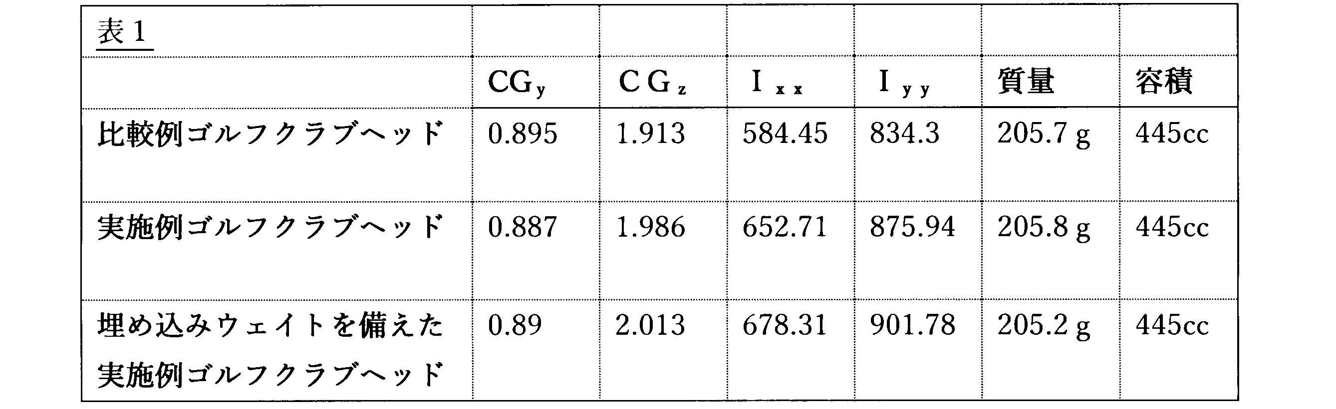
比較例クラブヘッドおよび実施例クラブヘッドは、約445cm3の同体積を有する。全体的に金属材料で構成された比較例クラブは、接地面(105)上のCGの高さである0.895インチのCGyを有する。実施例ゴルフクラブヘッドは、0.887インチのCGyを有する。CGyの値を小さくすることが望ましい。実施例ゴルフクラブヘッドのCGyは、比較例クラブのそれよりも0.008インチ低い。 The comparative club head and the example club head have the same volume of about 445 cm3 . The comparative club, constructed entirely of metal materials, has a CG height above the ground plane (105) of 0.895 inches. The example golf club head has a CG of 0.887 inches. It is desirable to reduce the value of CG. The CG of the example golf club head is 0.008 inches lower than that of the comparative club.
上述したように、CGzは、ロフト面(198)に垂直な方向に、打撃フェース中心(175)からゴルフクラブヘッドのリア端に向かって位置する距離として測定される。より大きなCGzは、ゴルフクラブのさらに後方に配置され、ボール飛行制御に有利である。比較例クラブのCGzは1.913インチである。実施例ゴルフクラブヘッドは、1.986インチのCGzを有する。実施例ゴルフクラブヘッドのCGzは、比較例クラブのCGzよりも0.073インチ後方にある。 As stated above, CGz is measured in a direction perpendicular to the loft plane (198) from the striking face center (175) toward the rear end of the golf club head. A larger CGz is located further back on the golf club and is beneficial for ball flight control. The comparative club has a CGz of 1.913 inches. The example golf club head has a CGz of 1.986 inches. The example golf club head's CGz is 0.073 inches further back than the comparative club's CGz.
CGの位置は、ボールの打ち上げ特性(例えば、ボール軌跡、ボールスピン、およびボール速度)、慣性モーメント(MOI)、および性能特性(例えば、スイング速度、インパクト中のスクエア)を決定するのに役立つ。高いMOIは、スイング中のゴルフクラブヘッドの回転を防止し、ボールとのインパクト中に打撃フェースをスクエアにするのに役立つ。スクエアな打撃フェースでボールをインパクトすることは、打撃フェースがスクエアでないときにボールをスライス又はフックすることと比較して、真っ直ぐなボール経路及び最適な高さ/軌道を確保するのに役立つ。また、CGが低いほど、ボールの速度とスピンが向上するため、距離を追加し、着地時にボールが後方に転がるのを防ぐことができる。 The location of the CG helps determine the ball launch characteristics (e.g., ball trajectory, ball spin, and ball velocity), moment of inertia (MOI), and performance characteristics (e.g., swing speed, square during impact). A high MOI helps prevent rotation of the golf club head during the swing and squares the striking face during impact with the ball. Impacting the ball with a square striking face helps ensure a straighter ball path and optimal height/trajectory compared to slicing or hooking the ball when the striking face is not square. A lower CG also improves ball speed and spin, adding distance and preventing the ball from rolling backwards upon landing.
実施例ゴルフクラブヘッドのMOIは比較例ゴルフクラブのMOIより大きい。IXXおよびIYYのMOI値はそれぞれ、X軸(190)およびY軸(192)の周りのMOI値である。高いMOIは、スイング中のゴルフクラブヘッドの回転を防止するのに役立ち、ボールとのインパクト中に打撃フェースをスクエアにするのに役立つので、より大きなMOIが望ましい。比較例クラブのIXX値は584.45であり、IYY値は834.30である。実施例ゴルフクラブヘッドのIXX値は652.71であり、IYY値は875.94である。実施例ゴルフクラブヘッドは、比較例クラブよりも、IXXが11.7%も改善され、IYYが5.0%改善されている。 The MOI of the example golf club head is greater than that of the comparative golf club. The IXX and IYY MOI values are the MOI values about the X-axis (190) and the Y-axis (192), respectively. A higher MOI is desirable because it helps prevent rotation of the golf club head during the swing and helps to square the striking face during impact with the ball. The comparative golf club has an IXX value of 584.45 and an IYY value of 834.30. The example golf club head has an IXX value of 652.71 and an IYY value of 875.94. The example golf club head has an 11.7% improvement in IXX and a 5.0% improvement in IYY over the comparative golf club.
実施例ゴルフクラブヘッドによって打たれたゴルフボールのボール飛行は、改善されたCGy値およびCGz値を有し、改善されたIXX値およびIYY値に直接的につながる。改善されたCG値は、インパクトでのより低いボールスピンを導き、ボール飛行のためのより長いキャリーを導く。 The ball flight of a golf ball struck by the example golf club head has improved CGy and CGz values, which translates directly to improved IXX and IYY values. Improved CG values lead to lower ball spin at impact, which leads to a longer carry for the ball flight.
代替の実施形態では、埋め込み高密度のウェイトが、実施例ゴルフクラブヘッドに追加された。ウェイトを有する実施例ゴルフクラブヘッドは、CGyが0.890インチであり、CGzが2.013インチである。ウェイトを有する実施例ゴルフクラブヘッドのCGyは、比較例ゴルフクラブヘッドのCGyより0.005インチ小さいが、ウェイトを有する実施例ゴルフクラブヘッドのCGzは、比較例ゴルフクラブヘッドのCGzより0.100インチ大きい。ウェイトを有する実施例ゴルフクラブヘッドは、IXX値が678.31であり、IYY値が901.78である。これらのMOI値は共に、比較例ゴルフクラブヘッドのIXXおよびIYYよりもそれぞれ16%および8.1%大きい。 In an alternative embodiment, embedded high density weights were added to the example golf club head. The example golf club head with the weights has a CGy of 0.890 inches and a CGz of 2.013 inches. The CGy of the example golf club head with the weights is 0.005 inches less than the CGy of the comparative golf club head, but the CGz of the example golf club head with the weights is 0.100 inches greater than the CGz of the comparative golf club head. The example golf club head with the weights has an IXX value of 678.31 and an IYY value of 901.78. Both of these MOI values are 16% and 8.1% greater than the IXX and IYY of the comparative golf club head, respectively.
1つ以上のクレームされた要素の置換は、再構成を構成し、修理を構成しない。更に、効果、他の利点、及び問題に対する解決策が特定の実施形態に関して記載されてきた。しかしながら、利点、他の有利な点及び問題に対する解決、並びに、任意の利点、有利な点または解決を発生させまたは明らかとさせる任意の1つまたは複数の要素は、このような利点、有利な点、解決または要素がこのような請求の範囲に明示的に述べられていない限り、請求の範囲の任意またはすべての要素の重大な、必須の、または、本質的な特徴若しくは要素を構成するものではない。 Substitution of one or more claimed elements constitutes a rearrangement, not a repair. Moreover, advantages, other benefits, and solutions to problems have been described with respect to particular embodiments. However, the advantages, other advantages, and solutions to problems, and any one or more elements that give rise to or make evident any advantage, advantage, or solution, do not constitute a critical, essential, or essential feature or element of any or all elements of a claim, unless such advantage, advantage, solution, or element is expressly recited in such claim.
ゴルフに対する規則は、時々変更される(全米ゴルフ協会(USGA)、英国ゴルフ協会(R&A)等のゴルフ標準組織及び/または管理機関によって、新しい規則が適用されることがあり、または、古いルールが撤廃若しくは変更されることがある)ため、本明細書に記載の装置、方法及び製品に関するゴルフ用品は、任意の特定時におけるゴルフのルールに適合しまたは適合しないことがある。したがって、本明細書に記載される方法、装置、および/または製品に関連するゴルフ用具は、適合または不適合のゴルフ用具として広告され、販売のために提供され、および/または販売されてもよい。本明細書に記載される方法、装置、および/または製品は、この点に関して限定されない。 Because the rules of golf change from time to time (new rules may be adopted, or old rules may be repealed or modified, by golf standards organizations and/or governing bodies such as the United States Golf Association (USGA), the Royal and American Golf Association (R&A), etc.), golf equipment related to the devices, methods, and products described herein may or may not conform to the rules of golf at any particular time. Accordingly, golf equipment related to the methods, devices, and/or products described herein may be advertised, offered for sale, and/or sold as conforming or non-conforming golf equipment. The methods, devices, and/or products described herein are not limited in this respect.
業界内の習慣、全米ゴルフ協会(USGA)またはR&Aなどのゴルフ団体によって設定された規則、および命名規則は、本出願の範囲から逸脱することなく、用語のこの説明を強化することができる。 Industry practices, rules established by golf organizations such as the United States Golf Association (USGA) or the R&A, and naming conventions may augment this description of terms without departing from the scope of this application.
上記の例は、中空体ゴルフクラブに関連して記載され得るが、本明細書に記載される装置、方法、および製品は、アイアン型ゴルフクラブ、ウェッジ型ゴルフクラブ、またはパター型ゴルフクラブなどの他のタイプのゴルフクラブに適用可能であり得る。あるいは、本明細書に記載の装置、方法、および製品は、ホッケースティック、テニスラケット、釣り用ポール、スキーポールなどの他のタイプのスポーツ用具に適用可能であってもよい。 Although the above examples may be described in relation to hollow-body golf clubs, the devices, methods, and products described herein may be applicable to other types of golf clubs, such as iron-type golf clubs, wedge-type golf clubs, or putter-type golf clubs. Alternatively, the devices, methods, and products described herein may be applicable to other types of sports equipment, such as hockey sticks, tennis racquets, fishing poles, ski poles, etc.
更に、本明細書に記載の実施形態及び限定事項は、実施形態及び/または限定事項が、(1)請求の範囲に明示的に主張されていない、及び、(2)均等論の下で、請求の範囲における表現要素及び/または限定事項と等価または潜在的に等価である場合、公開主義の下で公衆に提供するものではない。 Furthermore, the embodiments and limitations described herein are not offered to the public under the doctrine of disclosure if the embodiments and/or limitations (1) are not expressly claimed in the claims and (2) are equivalent or potentially equivalent to the expressive elements and/or limitations in the claims under the doctrine of equivalents.
本開示の様々な特徴および利点は、以下の項に記載される。 Various features and advantages of the present disclosure are described in the following sections.
項目1. ボディを備えるゴルフクラブヘッドであって、前記ボディは、打撃フェースと、リア端と、トウ端と、ヒール端と、クラウンと、ソールと、後縁部と、を備えており、前記ボディはさらに、前記打撃フェースと、打撃フェースリターンと、ウェイトチャネルをさらに有するリア延長部と、を有している第1の構成要素と、前記リア端の少なくとも一部を備える第2の構成要素と、を備えており、前記ウェイトチャネルが前記ゴルフクラブヘッドの前記リア端の中央に位置しており、前記打撃フェースは、打撃フェース中心を有しており、X軸が、前記ゴルフクラブヘッドの前記ヒール端から前記トウ端まで、且つ、前記クラブヘッドがアドレス位置にあるときに接地面に平行な方向に、前記打撃フェース中心を通って延びており、Y軸が、前記ゴルフクラブヘッドの前記クラウンから前記ソールまで、且つ、前記X軸に垂直な方向に、前記打撃フェースの中心を通って延びており、Z軸が、前記打撃フェースから前記ゴルフクラブヘッドのリア端まで、且つ、前記X軸及び前記Y軸に垂直な方向に、前記打撃フェース中心を通って延びており、前記打撃フェースにほぼ平行であって前記打撃フェース中心に接するロフト面が、前記接地面に対してロフト角を形成し、XY平面が、前記X軸と前記Y軸を通って延びており、YZ平面が、前記Y軸と前記Z軸を通って延びており、前記第1の構成要素は、第1の密度を有する第1の材料を備えており、前記第2の構成要素は、第2の密度を有する第2の材料を備えており、前記第1の密度が前記第2の密度よりも大きく、前記第1の構成要素の前記打撃フェースリターンは、前記打撃フェースから後方に延在し、第1の構成要素クラウン部と第1の構成要素ソール部を備えており、前記リア延長部は、前記打撃フェースリターンの前記第1の構成要素ソール部から前記リア端に向かって延びており、前記第2の構成要素は、前記第1の構成要素に結合されて、前記ゴルフクラブヘッドの囲まれた中空内部を形成するように構成されており、前記打撃フェースリターンの前記第1の構成要素ソール部はさらに、前記リア延長部のトウ側にあるトウ延長部と、前記リア延長部のヒール側にあるヒール延長部と、を備えており、前記トウ延長部は、トウ延長部リア壁を有しており、前記ヒール延長部は、ヒール延長部リア壁を有しており、前記第1の構成要素質量は、前記ゴルフクラブヘッドの質量の85%から96%である、ゴルフクラブヘッド。 Item 1. A golf club head comprising a body, the body comprising a striking face, a rear end, a toe end, a heel end, a crown, a sole, and a rear edge portion, the body further comprising a first component comprising the striking face, a striking face return, and a rear extension further having a weight channel, and a second component comprising at least a portion of the rear end, the weight channel being centrally located at the rear end of the golf club head, the striking face having a striking face center, and an X-axis of the golf club head. a Y-axis extends from the crown to the sole of the golf club head and through the center of the striking face in a direction perpendicular to the X-axis; a Z-axis extends from the striking face to the rear end of the golf club head and through the center of the striking face in a direction perpendicular to the X-axis and the Y-axis; and a loft plane that is substantially parallel to the striking face and tangent to the striking face center is disposed substantially perpendicular to the ground surface. a first component comprising a first material having a first density and a second component comprising a second material having a second density, the first density being greater than the second density; the striking face return of the first component extending rearwardly from the striking face and comprising a first component crown portion and a first component sole portion, the rear extension extending from the first component sole portion of the striking face return to the rear extension; A golf club head, the golf club head having a first component sole portion extending toward the end of the golf club head, the second component being configured to be coupled to the first component to form an enclosed hollow interior of the golf club head, the first component sole portion of the striking face return further comprising a toe extension on a toe side of the rear extension and a heel extension on a heel side of the rear extension, the toe extension having a toe extension rear wall, the heel extension having a heel extension rear wall, and the first component mass being 85% to 96% of the mass of the golf club head.
項目2. 前記ウェイトチャネルは、前記ボディの前記リア端と前記ソールにおいて露出している、項目1に記載のゴルフクラブヘッド。 Item 2. The golf club head according to item 1, wherein the weight channel is exposed at the rear end of the body and at the sole.
項目3. 前記ウェイトチャネルは、3つの位置のうちの1つにおいて可動ウェイトを受容するように構成されている、項目2に記載のゴルフクラブヘッド。 Item 3. The golf club head of item 2, wherein the weight channel is configured to receive a movable weight in one of three positions.
項目4. 前記リア延長部は、前記ウェイトチャネルを打撃フェースソールリターンに接続するトウ側壁とヒール側壁を備えている、項目1に記載のゴルフクラブヘッド。
項目5. 前記リア延長部トウ側壁と前記トウ延長部リア壁は、トウ側壁角度を形成し、前記リア延長部ヒール側壁と前記ヒール延長部は、ヒール側壁角度を形成する、項目4に記載のゴルフクラブヘッド。
Item 5. The golf club head according to
項目6. 前記トウ側壁角度と前記ヒール側壁角度は、角度の合計が180度になるように補角である、項目5に記載のゴルフクラブヘッド。 Item 6. The golf club head according to item 5, wherein the toe sidewall angle and the heel sidewall angle are complementary angles such that the sum of the angles is 180 degrees.
項目7. 前記リア延長部トウ側壁と前記トウ延長部リア壁は、トウ側交点で結合されており、前記リア延長部ヒール側壁と前記ヒール延長部は、ヒール側交点で結合されており、交点平面は、前記トウ側交点と前記ヒール側交点と一致し、前記XY平面と平行に延びている、項目4に記載のゴルフクラブヘッド。
Item 7. The golf club head according to
項目8. 前記ウェイトチャネルが、3つのねじ穴を有する取り付け壁をさらに備えており、前記3つのねじ穴が、トウ側ねじ穴と、中央ねじ穴と、ヒール側ねじ穴と、を備えており、前記中央ねじ穴が、前記取り付け壁の長さの中央に位置する、項目2に記載のゴルフクラブヘッド。 Item 8. The golf club head according to item 2, wherein the weight channel further comprises a mounting wall having three screw holes, the three screw holes comprising a toe screw hole, a central screw hole, and a heel screw hole, and the central screw hole is located in the center of the length of the mounting wall.
項目9. 前記リア延長部は、リア延長部前方中間点と取り付け壁中央穴の中心との間に延在するリア延長軸を備えており、前記リア延長部前方中間点は、前記トウ側交点と前記ヒール側交点との間の半分の位置にある、項目7に記載のゴルフクラブヘッド。 Item 9. The golf club head according to item 7, wherein the rear extension has a rear extension axis extending between a rear extension front midpoint and a center of the mounting wall central hole, and the rear extension front midpoint is halfway between the toe side intersection point and the heel side intersection point.
項目10. 前記リア延長軸は、前記交点平面に対して垂直である、項目9に記載のゴルフクラブヘッド。 Item 10. The golf club head according to item 9, wherein the rear extension axis is perpendicular to the intersection plane.
項目11. 前記リア延長軸は、前記交点平面に対して垂直ではない、項目9に記載のゴルフクラブヘッド。 Item 11. The golf club head of item 9, wherein the rear extension axis is not perpendicular to the intersection plane.
項目12. トウ側軸角度は、前記リア延長軸のトウ側において、前記ゴルフクラブヘッドのソールから見て測定される前記交点平面と前記リア延長軸との間の角度を有しており、ヒール側軸角度は、前記リア延長軸のヒール側において、前記ゴルフクラブヘッドのソールから見て測定される前記交点平面と前記リア延長軸との間の角度を有しており、前記トウ側軸角度と前記ヒール側軸角度は、180度となる補角である、項目9に記載のゴルフクラブヘッド。 Item 12. The golf club head according to item 9, wherein the toe side axis angle is an angle between the intersection plane and the rear extension axis measured on the toe side of the rear extension axis when viewed from the sole of the golf club head, and the heel side axis angle is an angle between the intersection plane and the rear extension axis measured on the heel side of the rear extension axis when viewed from the sole of the golf club head, and the toe side axis angle and the heel side axis angle are supplementary angles of 180 degrees.
項目13. 前記リア延長部は、前記ヒール端よりも前記ゴルフクラブヘッドの前記トウ端に近い前記打撃フェースリターンソール部に取り付けられており、前記トウ側軸角度は90度よりも大きく、前記ヒール側軸角度は90度よりも小さい、項目12に記載のゴルフクラブヘッド。 Item 13. The golf club head according to item 12, wherein the rear extension is attached to the striking face return sole portion closer to the toe end of the golf club head than the heel end, and the toe side axis angle is greater than 90 degrees and the heel side axis angle is less than 90 degrees.
項目14. 前記リア延長部は、前記トウ端よりも前記ゴルフクラブヘッドの前記ヒール端に近い前記打撃フェースリターンソール部に取り付けられており、前記ヒール側軸角度は90度よりも大きく、前記トウ側軸角度は90度よりも小さい、項目12に記載のゴルフクラブヘッド。 Item 14. The golf club head of item 12, wherein the rear extension is attached to the striking face return sole portion closer to the heel end of the golf club head than the toe end, and the heel side axis angle is greater than 90 degrees and the toe side axis angle is less than 90 degrees.
項目15. 前記リア延長部は、前記打撃フェースリターンソール部の後方周囲の後方において、ヒールからソール方向に測定されるリア延長部幅を備えており、前記リア延長部幅は、前記ソールの全幅の25%から85%の範囲である、項目1に記載のゴルフクラブヘッド。 Item 15. The golf club head of item 1, wherein the rear extension has a rear extension width measured in a heel-to-sole direction rearward of the rear periphery of the striking face return sole portion, the rear extension width being in the range of 25% to 85% of the overall width of the sole.
項目16. 前記ウェイトチャネルに隣接する前記リア延長部幅は、1インチから2.5インチの範囲とすることができる、項目15に記載のゴルフクラブヘッド。
項目17. トウ側交点とヒール側交点との間の前記リア延長部幅は、1インチから5インチの範囲とすることができる、項目15に記載のゴルフクラブヘッド。 Item 17. The golf club head according to item 15, wherein the rear extension width between the toe side intersection point and the heel side intersection point can range from 1 inch to 5 inches.
項目18. 可動ウェイトが、ねじ付き締結具によって固定される、項目3に記載のゴルフクラブヘッド。 Item 18. The golf club head of item 3, wherein the movable weight is secured by a threaded fastener.
項目19. 前記ウェイトチャネルがソール壁をさらに備えており、前記取り付け壁が前記ソールに対してほぼ垂直に配向されている、項目2に記載のゴルフクラブヘッド。 Item 19. The golf club head of item 2, wherein the weight channel further comprises a sole wall, and the mounting wall is oriented substantially perpendicular to the sole.
項目20. ボディを備えるゴルフクラブヘッドであって、前記ボディは、打撃フェースと、リア端と、トウ端と、ヒール端と、クラウンと、ソールと、後縁部と、を備えており、前記ボディはさらに、前記打撃フェースと、打撃フェースリターンと、ウェイトチャネルをさらに有するリア延長部と、を備えている、第1の構成要素と、前記リア端の少なくとも一部を備える第2の構成要素と、を備えており、前記打撃フェースは、打撃フェース中心を有しており、X軸が、前記ゴルフクラブヘッドの前記ヒール端から前記トウ端まで、且つ、前記クラブヘッドがアドレス位置にあるときに接地面に平行な方向に、前記打撃フェース中心を通って延びており、Y軸が、前記ゴルフクラブヘッドの前記クラウンから前記ソールまで、且つ、前記X軸に垂直な方向に、前記打撃フェースの中心を通って延びており、Z軸が、前記打撃フェースから前記ゴルフクラブヘッドのリア端まで、且つ、前記X軸及び前記Y軸に垂直な方向に、前記打撃フェース中心を通って延びており、
前記打撃フェースにほぼ平行であって前記打撃フェース中心に接するロフト面が、前記接地面に対してロフト角を形成し、XY平面が、前記X軸と前記Y軸を通って延びており、YZ平面が、前記Y軸と前記Z軸を通って延びており、前記第1の構成要素は、第1の密度を有する第1の材料を備えており、前記第2の構成要素は、第2の密度を有する第2の材料を備えており、前記第1の密度が前記第2の密度よりも大きく、前記第1の構成要素の前記打撃フェースリターンは、前記打撃フェースから後方に延在し、第1の構成要素クラウン部と第1の構成要素ソール部を備えており、前記リア延長部は、前記打撃フェースリターンの前記第1の構成要素ソール部から前記リア端に向かって延びており、前記第2の構成要素は、前記第1の構成要素に結合されて、前記ゴルフクラブヘッドの囲まれた中空内部を形成するように構成されており、前記打撃フェースリターンの前記第1の構成要素ソール部はさらに、前記リア延長部のトウ側のトウ延長部と、前記リア延長部のヒール側のヒール延長部と、を備えており、前記トウ延長部は、トウ延長部リア壁を有しており、前記ヒール延長部は、ヒール延長部リア壁を有しており、前記リア延長部は、幅と長さを有しており、前記リア延長部は、前記ウェイトチャネルを打撃フェースソールリターンに接続するトウ側壁とヒール側壁を備えており、前記リア延長部トウ側壁と前記トウ延長部リア壁は、トウ側壁角度を形成し、前記リア延長部ヒール側壁と前記ヒール延長部は、ヒール側壁角度を形成し、前記リア延長部トウ側壁と前記トウ延長部リア壁は、トウ側交点で結合されており、前記リア延長部ヒール側壁と前記ヒール延長部は、ヒール側交点で結合されており、交点平面は、前記トウ側交点と前記ヒール側交点と一致し、前記XY平面と平行に延びている、ゴルフクラブヘッド。
a loft plane generally parallel to the striking face and tangent to a center of the striking face that defines a loft angle with respect to the ground plane, an XY plane extending through the X axis and the Y axis, a YZ plane extending through the Y axis and the Z axis, the first component comprising a first material having a first density, the second component comprising a second material having a second density, the first density being greater than the second density, the striking face return of the first component extending rearwardly from the striking face and comprising a first component crown portion and a first component sole portion, the rear extension extending from the first component sole portion of the striking face return toward the rear end, the second component being configured to be coupled to the first component to form an enclosed hollow interior of the golf club head, the first component sole portion of the golf club head further comprises a toe extension on a toe side of the rear extension and a heel extension on a heel side of the rear extension, the toe extension having a toe extension rear wall, the heel extension having a heel extension rear wall, the rear extension having a width and a length, the rear extension having a toe sidewall and a heel sidewall connecting the weight channel to a striking face sole return, the rear extension toe sidewall and the toe extension rear wall forming a toe sidewall angle, the rear extension heel sidewall and the heel extension forming a heel sidewall angle, the rear extension toe sidewall and the toe extension rear wall being joined at a toe side intersection, the rear extension heel sidewall and the heel extension being joined at a heel side intersection, an intersection plane coinciding with the toe side intersection and the heel side intersection and extending parallel to the XY plane.
Claims (18)
前記ボディは、打撃フェースと、リア端と、トウ端と、ヒール端と、クラウンと、ソールと、後縁と、を備えており、
前記ボディはさらに、
前記打撃フェースと、打撃フェースリターンと、ウェイトチャネルをさらに有するリア延長部と、を備え、前記ウェイトチャネルが前記ゴルフクラブヘッドの前記リア端の中央に位置する、第1の構成要素と、
前記リア端の少なくとも一部を備える第2の構成要素と、を備えており、
前記打撃フェースは、打撃フェース中心を有しており、
X軸が、前記ゴルフクラブヘッドの前記ヒール端から前記トウ端まで、且つ、前記ゴルフクラブヘッドがアドレス位置にあるときに接地面に平行な方向に、前記打撃フェース中心を通って延びており、
Y軸が、前記ゴルフクラブヘッドの前記クラウンから前記ソールまで、且つ、前記X軸に垂直な方向に、前記打撃フェースの中心を通って延びており、
Z軸が、前記打撃フェースから前記ゴルフクラブヘッドのリア端まで、且つ、前記X軸及び前記Y軸に垂直な方向に、前記打撃フェース中心を通って延びており、
前記打撃フェースにほぼ平行であって前記打撃フェース中心に接するロフト面が、前記接地面に対してロフト角を形成し、
XY平面が、前記X軸と前記Y軸を通って延びており、
YZ平面が、前記Y軸と前記Z軸を通って延びており、
前記第1の構成要素は、第1の密度を有する第1の材料を備えており、
前記第2の構成要素は、第2の密度を有する第2の材料を備えており、
前記第1の密度が前記第2の密度よりも大きく、
前記第1の構成要素の前記打撃フェースリターンは、前記打撃フェースから後方に延在し、第1の構成要素クラウン部と第1の構成要素ソール部を備えており、
前記リア延長部は、前記打撃フェースリターンの前記第1の構成要素ソール部から前記リア端に向かって延びており、
前記第2の構成要素は、前記第1の構成要素に結合されて、前記ゴルフクラブヘッドの囲まれた中空内部を形成するように構成されており、
前記打撃フェースリターンの前記第1の構成要素ソール部はさらに、前記リア延長部のトウ側にあるトウ延長部と、前記リア延長部のヒール側にあるヒール延長部と、を備えており、
前記トウ延長部は、トウ延長部リア壁を有しており、前記ヒール延長部は、ヒール延長部リア壁を有しており、
前記第1の構成要素の質量は、前記ゴルフクラブヘッドの質量の85%から96%であり、
前記ウェイトチャネルは、前記ボディの前記リア端と前記ソールにおいて露出しており、
前記ウェイトチャネルは、3つの位置のうちの1つにおいて可動ウェイトを受容するように構成されている、ゴルフクラブヘッド。 A golf club head comprising a body,
the body having a striking face, a rear end, a toe end, a heel end, a crown, a sole, and a trailing edge;
The body further comprises:
a first component including the striking face, a striking face return, and a rear extension further having a weight channel, the weight channel being centrally located at the rear end of the golf club head;
and a second component comprising at least a portion of the rear end,
the striking face having a striking face center;
an X-axis extends from the heel end to the toe end of the golf club head and through the center of the striking face in a direction parallel to the ground plane when the golf club head is in an address position;
a Y-axis extends from the crown to the sole of the golf club head and perpendicular to the X-axis through the center of the striking face;
a Z-axis extends from the striking face to a rear end of the golf club head and through a center of the striking face in a direction perpendicular to the X-axis and the Y-axis;
a loft plane that is substantially parallel to the striking face and tangent to a center of the striking face forms a loft angle with respect to the ground contact surface;
an XY plane extends through the X-axis and the Y-axis;
a YZ plane extends through the Y axis and the Z axis;
the first component comprises a first material having a first density;
the second component comprises a second material having a second density;
the first density is greater than the second density;
the striking face return of the first component extends rearwardly from the striking face and includes a first component crown portion and a first component sole portion;
the rear extension extends from the first component sole portion of the striking face return toward the rear end;
the second component is configured to be coupled to the first component to form an enclosed hollow interior of the golf club head;
the first component sole portion of the striking face return further comprises a toe extension on a toe side of the rear extension and a heel extension on a heel side of the rear extension;
the toe extension has a toe extension rear wall, and the heel extension has a heel extension rear wall;
the mass of the first component is between 85% and 96% of the mass of the golf club head;
the weight channel is exposed at the rear end of the body and at the sole;
The weight channel is configured to receive a movable weight in one of three positions .
前記リア延長部の前記ヒール側壁と前記ヒール延長部リア壁は、ヒール側壁角度を形成する、請求項2に記載のゴルフクラブヘッド。 the toe sidewall of the rear extension and the toe extension rear wall form a toe sidewall angle;
The golf club head of claim 2 , wherein the heel sidewall of the rear extension and the heel extension rear wall form a heel sidewall angle.
交点平面は、前記トウ側交点と前記ヒール側交点と一致し、前記XY平面と平行に延びている、請求項4に記載のゴルフクラブヘッド。 the toe sidewall of the rear extension and the toe extension rear wall are joined at a toe side intersection, and the heel sidewall of the rear extension and the heel extension rear wall are joined at a heel side intersection,
The golf club head of claim 4 , wherein an intersection plane coincides with the toe-side intersection and the heel-side intersection and extends parallel to the XY plane.
前記3つのねじ穴が、トウ側ねじ穴と、中央ねじ穴と、ヒール側ねじ穴と、を備えており、
前記中央ねじ穴が、前記取り付け壁の長さの中央点に位置する、請求項1に記載のゴルフクラブヘッド。 the weight channel further comprises a mounting wall having three threaded holes;
The three screw holes include a toe side screw hole, a central screw hole, and a heel side screw hole,
The golf club head of claim 1 , wherein the central screw hole is located at a midpoint of the length of the mounting wall.
前記3つの穴が、トウ側穴と、中央穴と、ヒール側穴と、を備えており、
前記中央穴が、前記取り付け壁の長さの中央点に位置しており、
前記リア延長部は、リア延長部前方中間点と前記取り付け壁の前記中央穴の中心との間に延在するリア延長軸を備えており、
前記リア延長部前方中間点は、前記トウ側交点と前記ヒール側交点との間の半分の位置にある、請求項5に記載のゴルフクラブヘッド。 the weight channel further comprises a mounting wall having three holes;
The three holes include a toe side hole, a center hole, and a heel side hole,
the central hole is located at a midpoint of the length of the mounting wall;
the rear extension has a rear extension axis extending between a rear extension forward midpoint and a center of the central hole in the mounting wall;
The golf club head of claim 5 , wherein the rear extension front midpoint is halfway between the toe side intersection point and the heel side intersection point.
ヒール側軸角度は、前記リア延長軸のヒール側において、前記ゴルフクラブヘッドのソールから見て測定される前記交点平面と前記リア延長軸との間の角度を有しており、
前記トウ側軸角度と前記ヒール側軸角度は、180度となる補角である、請求項7に記載のゴルフクラブヘッド。 a toe-side axis angle is an angle between the intersection plane and the rear extension axis measured from the sole of the golf club head on the toe side of the rear extension axis;
a heel side axis angle is an angle between the intersection plane and the rear extension axis measured from a sole of the golf club head on the heel side of the rear extension axis;
8. The golf club head according to claim 7 , wherein the toe side axis angle and the heel side axis angle are supplementary angles of 180 degrees.
前記トウ側軸角度は90度よりも大きく、前記ヒール側軸角度は90度よりも小さい、請求項10に記載のゴルフクラブヘッド。 the rear extension is attached to the first component sole portion of the striking face return closer to the toe end of the golf club head than the heel end;
The golf club head of claim 10 , wherein the toe side axis angle is greater than 90 degrees and the heel side axis angle is less than 90 degrees.
前記ヒール側軸角度は90度よりも大きく、前記トウ側軸角度は90度よりも小さい、請求項10に記載のゴルフクラブヘッド。 the rear extension is attached to the first component sole portion of the striking face return closer to the heel end of the golf club head than the toe end;
The golf club head of claim 10 , wherein the heel side axis angle is greater than 90 degrees and the toe side axis angle is less than 90 degrees.
前記リア延長部幅は、前記ソールの全幅の25%から85%の範囲である、請求項1~12のいずれか一項に記載のゴルフクラブヘッド。 the rear extension comprises a rear extension width measured in a heel-to-sole direction rearward of a rear perimeter of the first component sole portion of the striking face return ;
The golf club head of any one of claims 1 to 12 , wherein the rear extension width is in the range of 25% to 85% of the overall width of the sole.
前記取り付け壁が前記ソールに対してほぼ垂直に配向されている、請求項6又は7に記載のゴルフクラブヘッド。 the weight channel further comprising a sole wall;
The golf club head of claim 6 or 7 , wherein the mounting wall is oriented substantially perpendicular to the sole.
前記ボディは、打撃フェースと、リア端と、トウ端と、ヒール端と、クラウンと、ソールと、後縁部と、を備えており、
前記ボディはさらに、
前記打撃フェースと、打撃フェースリターンと、ウェイトチャネルをさらに有するリア延長部と、を備えている、第1の構成要素と、
前記リア端の少なくとも一部を備える第2の構成要素と、を備えており、
前記打撃フェースは、打撃フェース中心を有しており、
X軸が、前記ゴルフクラブヘッドの前記ヒール端から前記トウ端まで、且つ、前記ゴルフクラブヘッドがアドレス位置にあるときに接地面に平行な方向に、前記打撃フェース中心を通って延びており、
Y軸が、前記ゴルフクラブヘッドの前記クラウンから前記ソールまで、且つ、前記X軸に垂直な方向に、前記打撃フェースの中心を通って延びており、
Z軸が、前記打撃フェースから前記ゴルフクラブヘッドのリア端まで、且つ、前記X軸及び前記Y軸に垂直な方向に、前記打撃フェース中心を通って延びており、
前記打撃フェースにほぼ平行であって前記打撃フェース中心に接するロフト面が、前記接地面に対してロフト角を形成し、
XY平面が、前記X軸と前記Y軸を通って延びており、
YZ平面が、前記Y軸と前記Z軸を通って延びており、
前記第1の構成要素は、第1の密度を有する第1の材料を備えており、
前記第2の構成要素は、第2の密度を有する第2の材料を備えており、
前記第1の密度が前記第2の密度よりも大きく、
前記第1の構成要素の前記打撃フェースリターンは、前記打撃フェースから後方に延在し、第1の構成要素クラウン部と第1の構成要素ソール部を備えており、
前記リア延長部は、前記打撃フェースリターンの前記第1の構成要素ソール部から前記リア端に向かって延びており、
前記第2の構成要素は、前記第1の構成要素に結合されて、前記ゴルフクラブヘッドの囲まれた中空内部を形成するように構成されており、
前記打撃フェースリターンの前記第1の構成要素ソール部はさらに、前記リア延長部のトウ側にあるトウ延長部と、前記リア延長部のヒール側にあるヒール延長部と、を備えており、
前記トウ延長部は、トウ延長部リア壁を有しており、前記ヒール延長部は、ヒール延長部リア壁を有しており、
前記リア延長部は、幅と長さを有しており、
前記リア延長部は、前記ウェイトチャネルを前記打撃フェースリターンの前記第1の構成要素ソール部に接続するトウ側壁とヒール側壁を備えており、
前記リア延長部の前記トウ側壁と前記トウ延長部リア壁は、トウ側壁角度を形成し、
前記リア延長部の前記ヒール側壁と前記ヒール延長部リア壁は、ヒール側壁角度を形成し、
前記リア延長部の前記トウ側壁と前記トウ延長部リア壁は、トウ側交点で結合されており、前記リア延長部の前記ヒール側壁と前記ヒール延長部リア壁は、ヒール側交点で結合されており、
交点平面は、前記トウ側交点と前記ヒール側交点と一致し、前記XY平面と平行に延びており、
前記ウェイトチャネルは、前記ボディの前記リア端と前記ソールにおいて露出しており、
前記ウェイトチャネルは、3つの位置のうちの1つにおいて可動ウェイトを受容するように構成されている、ゴルフクラブヘッド。
A golf club head comprising a body,
the body having a striking face, a rear end, a toe end, a heel end, a crown, a sole, and a trailing edge;
The body further comprises:
a first component comprising the striking face, a striking face return, and a rear extension further having a weight channel;
and a second component comprising at least a portion of the rear end,
the striking face having a striking face center;
an X-axis extends from the heel end to the toe end of the golf club head and through the center of the striking face in a direction parallel to the ground plane when the golf club head is in an address position;
a Y-axis extends from the crown to the sole of the golf club head and perpendicular to the X-axis through the center of the striking face;
a Z-axis extends from the striking face to a rear end of the golf club head and through a center of the striking face in a direction perpendicular to the X-axis and the Y-axis;
a loft plane that is substantially parallel to the striking face and tangent to a center of the striking face forms a loft angle with respect to the ground contact surface;
an XY plane extends through the X-axis and the Y-axis;
a YZ plane extends through the Y axis and the Z axis;
the first component comprises a first material having a first density;
the second component comprises a second material having a second density;
the first density is greater than the second density;
the striking face return of the first component extends rearwardly from the striking face and includes a first component crown portion and a first component sole portion;
the rear extension extends from the first component sole portion of the striking face return toward the rear end;
the second component is configured to be coupled to the first component to form an enclosed hollow interior of the golf club head;
the first component sole portion of the striking face return further comprises a toe extension on a toe side of the rear extension and a heel extension on a heel side of the rear extension;
the toe extension has a toe extension rear wall, and the heel extension has a heel extension rear wall;
The rear extension has a width and a length.
the rear extension includes a toe sidewall and a heel sidewall connecting the weight channel to the first component sole portion of the striking face return ;
the toe sidewall of the rear extension and the toe extension rear wall form a toe sidewall angle;
the heel sidewall of the rear extension and the heel extension rear wall form a heel sidewall angle;
the toe sidewall of the rear extension and the toe extension rear wall are joined at a toe side intersection, and the heel sidewall of the rear extension and the heel extension rear wall are joined at a heel side intersection,
The intersection plane coincides with the toe side intersection and the heel side intersection and extends parallel to the XY plane ;
the weight channel is exposed at the rear end of the body and at the sole;
The golf club head , wherein the weight channel is configured to receive a movable weight in one of three positions .
Priority Applications (1)
| Application Number | Priority Date | Filing Date | Title |
|---|---|---|---|
| JP2024194923A JP2025024026A (en) | 2019-07-24 | 2024-11-07 | Multi-element golf club head |
Applications Claiming Priority (3)
| Application Number | Priority Date | Filing Date | Title |
|---|---|---|---|
| US201962878263P | 2019-07-24 | 2019-07-24 | |
| US62/878,263 | 2019-07-24 | ||
| PCT/US2020/043483 WO2021016555A1 (en) | 2019-07-24 | 2020-07-24 | Multi-component golf club head |
Related Child Applications (1)
| Application Number | Title | Priority Date | Filing Date |
|---|---|---|---|
| JP2024194923A Division JP2025024026A (en) | 2019-07-24 | 2024-11-07 | Multi-element golf club head |
Publications (3)
| Publication Number | Publication Date |
|---|---|
| JP2022541625A JP2022541625A (en) | 2022-09-26 |
| JPWO2021016555A5 JPWO2021016555A5 (en) | 2023-07-31 |
| JP7586892B2 true JP7586892B2 (en) | 2024-11-19 |
Family
ID=74193080
Family Applications (2)
| Application Number | Title | Priority Date | Filing Date |
|---|---|---|---|
| JP2022504293A Active JP7586892B2 (en) | 2019-07-24 | 2020-07-24 | Multi-element golf club head |
| JP2024194923A Pending JP2025024026A (en) | 2019-07-24 | 2024-11-07 | Multi-element golf club head |
Family Applications After (1)
| Application Number | Title | Priority Date | Filing Date |
|---|---|---|---|
| JP2024194923A Pending JP2025024026A (en) | 2019-07-24 | 2024-11-07 | Multi-element golf club head |
Country Status (5)
| Country | Link |
|---|---|
| EP (1) | EP4003547A4 (en) |
| JP (2) | JP7586892B2 (en) |
| KR (2) | KR102845651B1 (en) |
| GB (5) | GB2621034B (en) |
| WO (1) | WO2021016555A1 (en) |
Families Citing this family (3)
| Publication number | Priority date | Publication date | Assignee | Title |
|---|---|---|---|---|
| US12390698B2 (en) * | 2013-08-05 | 2025-08-19 | Karsten Manufacturing Corporation | Polymeric golf club head with metallic face |
| US20240100402A1 (en) * | 2019-08-30 | 2024-03-28 | Taylor Made Golf Company, Inc. | Golf club heads |
| US20250161765A1 (en) * | 2023-11-22 | 2025-05-22 | Taylor Made Golf Company, Inc. | Golf club heads |
Citations (5)
| Publication number | Priority date | Publication date | Assignee | Title |
|---|---|---|---|---|
| JP2006102053A (en) | 2004-10-04 | 2006-04-20 | Bridgestone Sports Co Ltd | Golf club head |
| JP2008194454A (en) | 2007-02-12 | 2008-08-28 | Mizuno Corp | Golf club head |
| JP2011511664A (en) | 2008-02-11 | 2011-04-14 | ナイキ インコーポレーティッド | Golf club and golf club head having targeted weight characteristics |
| JP2011206244A (en) | 2010-03-30 | 2011-10-20 | Globeride Inc | Golf club |
| US20190176001A1 (en) | 2017-12-08 | 2019-06-13 | Karsten Manufacturing Corporation | Multi-component golf club head |
Family Cites Families (19)
| Publication number | Priority date | Publication date | Assignee | Title |
|---|---|---|---|---|
| US6558271B1 (en) * | 2000-01-18 | 2003-05-06 | Taylor Made Golf Company, Inc. | Golf club head skeletal support structure |
| US6623378B2 (en) * | 2001-06-11 | 2003-09-23 | Taylor Made Golf Company, Inc. | Method for manufacturing and golf club head |
| US6659884B2 (en) * | 2002-02-01 | 2003-12-09 | Panda Golf, Inc. | Golf club head |
| JP2005287952A (en) * | 2004-04-02 | 2005-10-20 | Bridgestone Sports Co Ltd | Golf club head |
| JP2006130065A (en) * | 2004-11-05 | 2006-05-25 | Bridgestone Sports Co Ltd | Golf club head |
| US7070514B1 (en) * | 2005-04-05 | 2006-07-04 | Borunda William C | Golf club head having internal impact assembly |
| US9314676B2 (en) | 2013-10-02 | 2016-04-19 | Karsten Manufacutring Corporation | Golf club heads with ribs and related methods |
| US7601078B2 (en) | 2007-03-29 | 2009-10-13 | Karsten Manufacturing Corporation | Golf club head with non-metallic body |
| US7959522B2 (en) * | 2008-08-12 | 2011-06-14 | Dick's Sporting Goods, Inc. | Golf driver head with exchangeable rear sections |
| US8133128B2 (en) * | 2008-08-15 | 2012-03-13 | Nike, Inc. | Golf club head and system |
| US10046212B2 (en) * | 2009-12-23 | 2018-08-14 | Taylor Made Golf Company, Inc. | Golf club head |
| US9440126B2 (en) * | 2010-09-30 | 2016-09-13 | Robert Boyd | Golf club and golf club head structures |
| US9687705B2 (en) * | 2010-11-30 | 2017-06-27 | Nike, Inc. | Golf club head or other ball striking device having impact-influencing body features |
| JP5749479B2 (en) * | 2010-12-07 | 2015-07-15 | ブリヂストンスポーツ株式会社 | Golf club head |
| US9861865B1 (en) * | 2014-12-24 | 2018-01-09 | Taylor Made Golf Company, Inc. | Hollow golf club head with step-down crown and shroud forming second cavity |
| US9868036B1 (en) * | 2015-08-14 | 2018-01-16 | Taylormade Golf Company, Inc. | Golf club head |
| GB2600264B (en) * | 2016-05-25 | 2022-12-28 | Karsten Mfg Corp | Adjustable weight club head |
| KR20250136947A (en) * | 2017-08-15 | 2025-09-16 | 카스턴 매뉴팩츄어링 코오포레이숀 | Adjustable weight club head |
| EP3897882B1 (en) * | 2018-12-21 | 2024-11-13 | Karsten Manufacturing Corporation | Golf club head with stiffening ribs |
-
2020
- 2020-07-24 WO PCT/US2020/043483 patent/WO2021016555A1/en not_active Ceased
- 2020-07-24 GB GB2316175.5A patent/GB2621034B/en active Active
- 2020-07-24 GB GB2311364.0A patent/GB2618455B/en active Active
- 2020-07-24 KR KR1020227006123A patent/KR102845651B1/en active Active
- 2020-07-24 GB GB2311363.2A patent/GB2618454B/en active Active
- 2020-07-24 JP JP2022504293A patent/JP7586892B2/en active Active
- 2020-07-24 GB GB2201469.0A patent/GB2600615B/en active Active
- 2020-07-24 KR KR1020257026460A patent/KR20250125439A/en active Pending
- 2020-07-24 EP EP20845129.4A patent/EP4003547A4/en active Pending
- 2020-07-24 GB GB2311366.5A patent/GB2618456B/en active Active
-
2024
- 2024-11-07 JP JP2024194923A patent/JP2025024026A/en active Pending
Patent Citations (5)
| Publication number | Priority date | Publication date | Assignee | Title |
|---|---|---|---|---|
| JP2006102053A (en) | 2004-10-04 | 2006-04-20 | Bridgestone Sports Co Ltd | Golf club head |
| JP2008194454A (en) | 2007-02-12 | 2008-08-28 | Mizuno Corp | Golf club head |
| JP2011511664A (en) | 2008-02-11 | 2011-04-14 | ナイキ インコーポレーティッド | Golf club and golf club head having targeted weight characteristics |
| JP2011206244A (en) | 2010-03-30 | 2011-10-20 | Globeride Inc | Golf club |
| US20190176001A1 (en) | 2017-12-08 | 2019-06-13 | Karsten Manufacturing Corporation | Multi-component golf club head |
Also Published As
| Publication number | Publication date |
|---|---|
| GB202316175D0 (en) | 2023-12-06 |
| GB2618455B (en) | 2024-04-03 |
| GB2618455A (en) | 2023-11-08 |
| GB2621034A (en) | 2024-01-31 |
| GB202311363D0 (en) | 2023-09-06 |
| GB202311364D0 (en) | 2023-09-06 |
| GB2600615B (en) | 2023-11-01 |
| EP4003547A1 (en) | 2022-06-01 |
| GB2618454A (en) | 2023-11-08 |
| GB2618456B (en) | 2024-04-03 |
| KR20250125439A (en) | 2025-08-21 |
| KR20220038738A (en) | 2022-03-29 |
| GB202311366D0 (en) | 2023-09-06 |
| GB2618454B (en) | 2024-04-03 |
| JP2022541625A (en) | 2022-09-26 |
| JP2025024026A (en) | 2025-02-19 |
| EP4003547A4 (en) | 2023-08-30 |
| GB2621034B (en) | 2024-05-22 |
| GB2618456A (en) | 2023-11-08 |
| KR102845651B1 (en) | 2025-08-12 |
| GB2600615A (en) | 2022-05-04 |
| WO2021016555A1 (en) | 2021-01-28 |
Similar Documents
| Publication | Publication Date | Title |
|---|---|---|
| US12296241B2 (en) | Multi-component golf club head | |
| US11517799B2 (en) | Multi-component golf club head | |
| US11931631B2 (en) | Golf club head | |
| US12434111B2 (en) | Golf club heads and methods to manufacture golf club heads | |
| US20260041969A1 (en) | Golf club head | |
| JP2025024026A (en) | Multi-element golf club head | |
| KR20250008948A (en) | Co-molded golf club heads | |
| JP2022513816A (en) | Mixed material golf club head | |
| JP2025090634A (en) | Multi-element golf club head | |
| KR20250099247A (en) | Golf club head with low CG and high MOI | |
| WO2026055387A1 (en) | Multi-component golf club head |
Legal Events
| Date | Code | Title | Description |
|---|---|---|---|
| A521 | Request for written amendment filed |
Free format text: JAPANESE INTERMEDIATE CODE: A523 Effective date: 20230721 |
|
| A621 | Written request for application examination |
Free format text: JAPANESE INTERMEDIATE CODE: A621 Effective date: 20230721 |
|
| A977 | Report on retrieval |
Free format text: JAPANESE INTERMEDIATE CODE: A971007 Effective date: 20240515 |
|
| A131 | Notification of reasons for refusal |
Free format text: JAPANESE INTERMEDIATE CODE: A131 Effective date: 20240702 |
|
| A521 | Request for written amendment filed |
Free format text: JAPANESE INTERMEDIATE CODE: A523 Effective date: 20240930 |
|
| TRDD | Decision of grant or rejection written | ||
| A01 | Written decision to grant a patent or to grant a registration (utility model) |
Free format text: JAPANESE INTERMEDIATE CODE: A01 Effective date: 20241008 |
|
| A61 | First payment of annual fees (during grant procedure) |
Free format text: JAPANESE INTERMEDIATE CODE: A61 Effective date: 20241107 |
|
| R150 | Certificate of patent or registration of utility model |
Ref document number: 7586892 Country of ref document: JP Free format text: JAPANESE INTERMEDIATE CODE: R150 |