JP7586854B2 - Vehicle-mounted antenna device and vehicle-mounted communication system - Google Patents
Vehicle-mounted antenna device and vehicle-mounted communication system Download PDFInfo
- Publication number
- JP7586854B2 JP7586854B2 JP2022079961A JP2022079961A JP7586854B2 JP 7586854 B2 JP7586854 B2 JP 7586854B2 JP 2022079961 A JP2022079961 A JP 2022079961A JP 2022079961 A JP2022079961 A JP 2022079961A JP 7586854 B2 JP7586854 B2 JP 7586854B2
- Authority
- JP
- Japan
- Prior art keywords
- antenna
- vehicle
- substrate
- tel
- antenna device
- Prior art date
- Legal status (The legal status is an assumption and is not a legal conclusion. Google has not performed a legal analysis and makes no representation as to the accuracy of the status listed.)
- Active
Links
- 238000004891 communication Methods 0.000 title claims description 40
- 239000000758 substrate Substances 0.000 claims description 74
- 239000002184 metal Substances 0.000 claims description 9
- 238000009434 installation Methods 0.000 description 13
- 238000010586 diagram Methods 0.000 description 8
- 230000005856 abnormality Effects 0.000 description 6
- 230000005540 biological transmission Effects 0.000 description 6
- 239000003990 capacitor Substances 0.000 description 3
- 230000008878 coupling Effects 0.000 description 1
- 238000010168 coupling process Methods 0.000 description 1
- 238000005859 coupling reaction Methods 0.000 description 1
- 238000005516 engineering process Methods 0.000 description 1
- 239000000463 material Substances 0.000 description 1
- 239000007769 metal material Substances 0.000 description 1
- 238000012986 modification Methods 0.000 description 1
- 230000004048 modification Effects 0.000 description 1
- 238000006467 substitution reaction Methods 0.000 description 1
Images


Classifications
-
- H—ELECTRICITY
- H01—ELECTRIC ELEMENTS
- H01Q—ANTENNAS, i.e. RADIO AERIALS
- H01Q21/00—Antenna arrays or systems
- H01Q21/28—Combinations of substantially independent non-interacting antenna units or systems
-
- H—ELECTRICITY
- H01—ELECTRIC ELEMENTS
- H01Q—ANTENNAS, i.e. RADIO AERIALS
- H01Q1/00—Details of, or arrangements associated with, antennas
- H01Q1/27—Adaptation for use in or on movable bodies
- H01Q1/32—Adaptation for use in or on road or rail vehicles
- H01Q1/3208—Adaptation for use in or on road or rail vehicles characterised by the application wherein the antenna is used
- H01Q1/3233—Adaptation for use in or on road or rail vehicles characterised by the application wherein the antenna is used particular used as part of a sensor or in a security system, e.g. for automotive radar, navigation systems
-
- H—ELECTRICITY
- H01—ELECTRIC ELEMENTS
- H01Q—ANTENNAS, i.e. RADIO AERIALS
- H01Q1/00—Details of, or arrangements associated with, antennas
- H01Q1/48—Earthing means; Earth screens; Counterpoises
-
- H—ELECTRICITY
- H01—ELECTRIC ELEMENTS
- H01Q—ANTENNAS, i.e. RADIO AERIALS
- H01Q21/00—Antenna arrays or systems
-
- H—ELECTRICITY
- H01—ELECTRIC ELEMENTS
- H01Q—ANTENNAS, i.e. RADIO AERIALS
- H01Q5/00—Arrangements for simultaneous operation of antennas on two or more different wavebands, e.g. dual-band or multi-band arrangements
- H01Q5/30—Arrangements for providing operation on different wavebands
- H01Q5/307—Individual or coupled radiating elements, each element being fed in an unspecified way
- H01Q5/342—Individual or coupled radiating elements, each element being fed in an unspecified way for different propagation modes
- H01Q5/357—Individual or coupled radiating elements, each element being fed in an unspecified way for different propagation modes using a single feed point
- H01Q5/364—Creating multiple current paths
- H01Q5/371—Branching current paths
-
- H—ELECTRICITY
- H01—ELECTRIC ELEMENTS
- H01Q—ANTENNAS, i.e. RADIO AERIALS
- H01Q5/00—Arrangements for simultaneous operation of antennas on two or more different wavebands, e.g. dual-band or multi-band arrangements
- H01Q5/40—Imbricated or interleaved structures; Combined or electromagnetically coupled arrangements, e.g. comprising two or more non-connected fed radiating elements
-
- H—ELECTRICITY
- H01—ELECTRIC ELEMENTS
- H01Q—ANTENNAS, i.e. RADIO AERIALS
- H01Q9/00—Electrically-short antennas having dimensions not more than twice the operating wavelength and consisting of conductive active radiating elements
- H01Q9/04—Resonant antennas
- H01Q9/0407—Substantially flat resonant element parallel to ground plane, e.g. patch antenna
- H01Q9/0421—Substantially flat resonant element parallel to ground plane, e.g. patch antenna with a shorting wall or a shorting pin at one end of the element
Landscapes
- Engineering & Computer Science (AREA)
- Computer Security & Cryptography (AREA)
- Radar, Positioning & Navigation (AREA)
- Remote Sensing (AREA)
- Physics & Mathematics (AREA)
- Electromagnetism (AREA)
- Variable-Direction Aerials And Aerial Arrays (AREA)
- Waveguide Aerials (AREA)
- Details Of Aerials (AREA)
Description
本発明は、車載アンテナ装置及び車載通信システムに関する。 The present invention relates to an in-vehicle antenna device and an in-vehicle communication system.
車両に異常が発生した場合に、異常が発生した車両の状態や位置情報などのデータをコールセンターへ送信し、コールセンターとの音声通話を実現する車両緊急通報システムが提案されている。この車両緊急通報システムに関してコールセンターへの通信を実現するためのアンテナ装置が提案されており、特許文献1には、コールセンターとの通信を可能とするアンテナ装置が開示されている。特許文献1に開示されたアンテナ装置は、テレマティクス用広帯域アンテナの上にGNSS用アンテナを設けることで、データ送受信用と、音声通話用とで異なる通信手段に対応した複数のアンテナを複合化する。 A vehicle emergency notification system has been proposed that, when an abnormality occurs in a vehicle, transmits data such as the vehicle's condition and location to a call center, enabling a voice call with the call center. An antenna device has been proposed for enabling communication with the call center in relation to this vehicle emergency notification system, and Patent Document 1 discloses an antenna device that enables communication with the call center. The antenna device disclosed in Patent Document 1 combines multiple antennas corresponding to different communication means for data transmission and reception and for voice calls by providing a GNSS antenna on top of a telematics wideband antenna.
しかし、車両にアンテナを設置する場合には、車両内の限られた領域にアンテナを設置することになるため、そのアンテナ装置自体の形状に対しては、コンパクト化が求められる。一方で、車両に搭載された車載システム等が扱うデータ量の増加に伴い、車両に搭載されるアンテナ装置は大量のデータを扱いつつ、そのデータに対する通信品質の向上が求められる。特許文献1に記載されたアンテナ装置においては、GNSS用アンテナをテレマティクス用広帯域アンテナの上に積層して配置させる。そのため、当該アンテナ装置は上下方向に対して所定の大きさが必要となり、さらにGNSS用アンテナの配置により、テレマティクス用広帯域アンテナへの通信品質に影響が及ぼされる。そのため、車両への設置に適した形状と、高い通信品質とを実現可能なアンテナ装置が求められる。 However, when installing an antenna in a vehicle, the antenna is installed in a limited area inside the vehicle, and therefore the shape of the antenna device itself must be compact. On the other hand, as the amount of data handled by on-board systems and the like installed in vehicles increases, antenna devices installed in vehicles are required to handle large amounts of data while improving the communication quality for that data. In the antenna device described in Patent Document 1, the GNSS antenna is stacked on top of the telematics wideband antenna. For this reason, the antenna device needs to have a certain size in the vertical direction, and furthermore, the placement of the GNSS antenna affects the communication quality for the telematics wideband antenna. For this reason, an antenna device that can achieve a shape suitable for installation in a vehicle and high communication quality is required.
本発明は、このような従来技術が有する課題に鑑みてなされたものである。そして本発明の目的は、車両への設置に適し、かつ高い通信品質を実現することが可能な車載アンテナ装置を提供することにある。 The present invention was made in consideration of the problems inherent in the conventional technology. The object of the present invention is to provide an in-vehicle antenna device that is suitable for installation in a vehicle and is capable of achieving high communication quality.
本発明の態様に係る車載アンテナ装置は、車両に設置される車載アンテナ装置であって、アンテナ基板と、アンテナ部が給電部及びGND接地部を介してアンテナ基板と電気的に接続された板状アンテナであって、アンテナ部がアンテナ基板の基板平面に対して垂直な方向である第1方向に所定の長さ離れた位置にアンテナ基板の基板平面に対して平行となるように設置された複数のTELアンテナ(Telematics)と、第1方向において、上面とアンテナ基板との距離が所定の長さより短くなるようにアンテナ基板に設置されたGNSSアンテナ(Global Navigation Satellite System)と、を備える。 The vehicle-mounted antenna device according to an embodiment of the present invention is an on-vehicle antenna device installed in a vehicle, and includes an antenna substrate, a plate-shaped antenna having an antenna portion electrically connected to the antenna substrate via a power supply portion and a GND ground portion, and a plurality of TEL antennas (Telematics) installed so that the antenna portions are parallel to the substrate plane of the antenna substrate at positions spaced a predetermined distance in a first direction, which is a direction perpendicular to the substrate plane of the antenna substrate, and a GNSS antenna (Global Navigation Satellite System) installed on the antenna substrate so that the distance between the top surface and the antenna substrate in the first direction is shorter than a predetermined length.
本発明の他の態様に係る車載通信システムは、上述の車載アンテナ装置と、緊急コール用スピーカと、マイクと、緊急コールスイッチと、を備える。 An in-vehicle communication system according to another aspect of the present invention includes the in-vehicle antenna device described above, an emergency call speaker, a microphone, and an emergency call switch.
本発明によれば、車両への設置に適し、かつ高い通信品質を実現することが可能な車載アンテナ装置を提供することができる。 The present invention provides an in-vehicle antenna device that is suitable for installation in a vehicle and can achieve high communication quality.
以下、図面を用いて本実施形態に係る車載アンテナ装置10について詳細に説明する。なお、図面の寸法比率は説明の都合上誇張されており、実際の比率と異なる場合がある。また、以下の図面の記載において、同一又は類似の部分には同一又は類似の符号を付している。
The vehicle-mounted
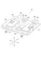
図1Aは、本実施形態に係る車載アンテナ装置10の外観を示す斜視図である。図1Aに示す例においては、車載アンテナ装置10が筐体20によって覆われている状態を示している。本実施形態に係る車載アンテナ装置10は、例えば車両に異常が発生した場合に、車両の外部のコールセンターに車両の状態や位置情報を通知し、また、コールセンターとの緊急の通話を可能とする装置である。
Figure 1A is a perspective view showing the exterior of the vehicle-mounted
図1Bは、筐体20の内部に格納された車載アンテナ装置10の構成を説明するための図である。図1Bに示すように、車載アンテナ装置10は、アンテナ基板30の上に、二つのTELアンテナ100a、100b(Telematics)が設置されている。また、車載アンテナ装置10は、アンテナ基板30の上に、GNSSアンテナ200(Global Navigation Satellite System)が設置されている。
Figure 1B is a diagram for explaining the configuration of the vehicle-mounted
TELアンテナ100a、100bは、携帯電話通信網を通じて緊急通報サービスを提供するコールセンター(ネットワークサーバ)との通信を実現するためのアンテナである。また、TELアンテナ100a、100bは、例えば4G、5G(Generation)等の携帯電話通信用アンテナであり、電話回線を通じたコールセンターとの音声通話を実現する。また、車載アンテナ装置10は、後述のGNSSアンテナ200によって取得された車両の位置情報を、TELアンテナ100a、100bを介して、コールセンターに送信する。
The
GNSSアンテナ200は、複数の測位衛星から時刻情報つきの信号を受信するためのアンテナである。GNSSアンテナ200により、位置や速度方位の算出及び高精度な時刻の取得ができ、地上における車両の現在位置を計測することが可能となる。
The
また、車載アンテナ装置10は、アンプ回路部210と、バックアップバッテリ300と、コネクタ400と、電解コンデンサ500と、を備える。
The vehicle-mounted
アンプ回路部210は、GNSSアンテナ200で受信した信号を増幅する機能を備える。
The
バックアップバッテリ300は、車載アンテナ装置10を動作させるための補助バッテリである。例えば、車両に異常が発生し、車両から車載アンテナ装置10への電源供給が断たれた状態においても、車載アンテナ装置10が継続して動作することを可能とする。なお、バックアップバッテリ300は、図1Aに示す筐体20のバッテリ蓋部23を個別に開閉することで、車載アンテナ装置10とは独立して、取り外し及び取り付けが可能となる。
The
コネクタ400は、車載アンテナ装置10と、車両内の他の装置とを接続するためのコネクタである。車両内の他の装置については後述する。電解コンデンサ500は、車載アンテナ装置10の電源回路の構成部品である。
The
なお、以下の説明では、図1A及び図1Bに示すアンテナ基板30の長手方向をX軸方向とし、短手方向をY軸方向として定める。よって、図1A及び図1Bに示すアンテナ基板30の基板平面は、X軸及びY軸によって形成されるXY平面と平行となる。また、アンテナ基板30の基板平面に対して垂直となる方向をZ軸方向として定める。
In the following description, the longitudinal direction of the
また、X1方向は、図1A及び図1BにおいてX軸方向の図面向かって右下方向を意味し、X2方向は、X1方向とは逆の方向を意味する。また、Y1方向は、図1A及び図1Bに示すように、Y軸方向の図面向かって左下方向を意味し、Y2方向は、Y1方向とは逆の方向を意味する。さらに、Z1方向は、Z軸方向において、アンテナ基板30の基板平面に対し、図面向かって上側への方向を意味し、Z2方向は、Z1方向とは逆の方向(図面向かって下側への方向)を意味する。なお、Z1方向は第1方向に相当する。
The X1 direction refers to the lower right direction in the X-axis direction in Figures 1A and 1B, and the X2 direction refers to the opposite direction to the X1 direction. The Y1 direction refers to the lower left direction in the Y-axis direction in Figures 1A and 1B, and the Y2 direction refers to the opposite direction to the Y1 direction. The Z1 direction refers to the upward direction in the Z-axis direction with respect to the substrate plane of the
(車載アンテナ装置10の機能的構成)
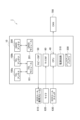
図2は、本実施形態に係る車載アンテナ装置10の機能的構成及び車載アンテナ装置10を備える車載通信システム1(車両緊急通報システム)の構成を示すブロック図である。図2に示すように、車載アンテナ装置10は、CPU40と、スピーカIF50と、マイクIF60と、電源回路310と、バックアップバッテリ300と、を備える。また、車載アンテナ装置10は、TELアンテナ100a、100bと、GNSSアンテナ200と、TELモジュール101と、GNSSモジュール201とを備える。以降、TELアンテナのそれぞれを区別して説明する必要がない場合は、単に「TELアンテナ100」と表記する。
(Functional configuration of the vehicle-mounted antenna device 10)
Fig. 2 is a block diagram showing the functional configuration of the vehicle-mounted
CPU40は、例えば、オペレーティングシステムを動作させて、車載アンテナ装置10全体を制御する。さらに、CPU40は、例えば、記憶部(図示なし)に格納されたプログラムに基づいて動作し、車載アンテナ装置10の各機能を実行する。
The
また、CPU40は、SOSコールスイッチ630と、CAN700(Controller Area Network)と接続される。例えば、車両において異常が発生した場合に、車両の搭乗者等はSOSコールスイッチ630を押下することで、その押下した情報がCPU40に送信される。SOSコールスイッチ630からの押下の情報を取得したCPU40は、車載アンテナ装置10が備える車両緊急通報用の機能を作動させる。
The
また、車載通信システム1は、車両の異常発生時にエアバッグ(図示なし)等が作動することによって、その情報がCAN700を介して車載アンテナ装置10に送信されることによっても作動する。なお、SOSコールスイッチ630は、緊急コールスイッチに相当する。
The in-vehicle communication system 1 also operates when an airbag (not shown) or the like is activated in the event of a vehicle abnormality, and the information is sent to the in-
スピーカIF50は、SOSコール専用スピーカ610と接続され、TELアンテナ100を介して受信したコールセンターからの音声等をSOSコール専用スピーカ610から出力する。なお、SOSコール専用スピーカ610は、緊急コール用スピーカに相当する。
The speaker IF50 is connected to a
マイクIF60は、マイク620と接続され、ユーザが発した音声を取得し、TELアンテナ100を介して、コールセンターに送る。
The microphone IF 60 is connected to the
電源回路310は、車載アンテナ装置10の電源系統を制御する装置であり、車両から供給される電力を車載アンテナ装置10に分配する。また、車両に異常が発生した場合には、電源系統をバックアップバッテリ300に切り替える。
The power supply circuit 310 is a device that controls the power supply system of the vehicle-mounted
TELモジュール101及びGNSSモジュール201は、それぞれTELアンテナ100及びGNSSアンテナ200を介して送受信されるデータを処理するためのモジュールである。
The
(TELアンテナの構成)
次に図3A乃至図3Cを参照してTELアンテナ100の構成について説明する。
(Configuration of TEL antenna)
Next, the configuration of the
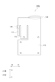
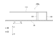
図3Aは、TELアンテナ100aをアンテナ基板30の上方向から見た場合の平面模式図である。また、図3Bは、TELアンテナ100aを図1BにおけるY2方向に向かって見た場合の模式図である。さらに、図3Cは、TELアンテナ100aを図1BにおけるX2方向に向かって見た場合の模式図である。
Figure 3A is a schematic plan view of the
図3Aに示すように、TELアンテナ100aは、アンテナ部として、アンテナ素子111、アンテナ素子112、及びアンテナ素子113を備える。アンテナ素子111は、3.7GHz帯用のアンテナ素子である。また、アンテナ素子112は、2GHz帯用のアンテナ素子である。また、アンテナ素子113は、800MHz帯用のアンテナ素子である。このようにTELアンテナ100のアンテナ部が複数のアンテナ素子111、112、及び113を備えることで、車載アンテナ装置10は、複数の周波数帯で車両の外部のコールセンターとの通信が可能となる。
As shown in FIG. 3A, the
また、TELアンテナ100aのアンテナ部は、図3B及び図3Cに示すように給電部120及びGND接地部130を介してアンテナ基板30と電気的に接続された板状アンテナである。
The antenna section of the
また、TELアンテナ100aのアンテナ部は、図3B及び図3Cに示すように、アンテナ基板30の基板平面に対して垂直な方向に所定の長さ離れた位置にアンテナ基板30の基板平面に対して平行となるように設置される。本実施形態において、TELアンテナ100のアンテナ部とアンテナ基板30との距離を示す所定の長さは、アンテナ部の各アンテナ素子の垂直偏波の送受信効率に関係する。すなわち、この所定の長さは、各アンテナ素子に対応させる周波数帯の波長と各アンテナ素子に影響がある周辺部品との関係に基づいて長さを最適化することにより決定される。例えば、本実施形態においてTELアンテナ100のアンテナ部とアンテナ基板30との距離を示す所定の長さは、15mmである。
The antenna section of the
なお、このTELアンテナ100のアンテナ部とアンテナ基板30との距離を示す所定の長さを15mmとする構成は、本実施形態の構成を限定するものではない。TELアンテナ100のアンテナ部とアンテナ基板30との距離を示す所定の長さは、TELアンテナ100の通信品質を向上させるために15mmより短い又は長い構成としてもよい。また、TELアンテナ100に用いられる材料の寸法精度が10分の1ミリ単位である場合、対象となる周波数帯に合わせて、10分の1ミリ単位で当該所定の長さの寸法管理を行うことで、TELアンテナ100の通信品質を向上させることが可能となる。
Note that the configuration in which the predetermined length indicating the distance between the antenna portion of the
また、本実施形態においては、TELアンテナ100bは、X軸方向において、TELアンテナ100aと対称な構成となる。すなわち、TELアンテナ100bは、TELアンテナ100aと同じアンテナ素子111、112、113を備えるアンテナ部を有する。
In addition, in this embodiment, the
また、TELアンテナ100a及びTELアンテナ100bは、アンテナ基板30の基板平面と平行となる方向に所定の距離だけ離れて設置される。本実施形態においては、TELアンテナ100a及びTELアンテナ100bは、図1Bに示すように、X1方向及びX2方向に所定の距離だけ離れて設置されている。ここで、TELアンテナ100a及びTELアンテナ100bが離れて設置される所定の距離は、TELアンテナ100a及びTELアンテナ100bが電波干渉により結合しない程度の距離である。
The
このように複数のTELアンテナ100を備えることで、車載アンテナ装置10は、MIMO(multiple-input and multiple-output)を適用し通信品質を向上させることが可能となる。
By having
(GNSSアンテナの構成)
次に、GNSSアンテナ200の構成について説明する。
(GNSS antenna configuration)
Next, the configuration of the
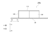
GNSSアンテナ200は、図1Bに示すように、Z1方向において、GNSSアンテナ200の上面とアンテナ基板30との距離が、TELアンテナ100のアンテナ部とアンテナ基板30との距離より短くなるようにアンテナ基板30に設置される。
As shown in FIG. 1B, the
また、車載アンテナ装置10は、アンテナ基板30上のGNSSアンテナ200に対する所定の方向においては、通信を遮蔽する特定の金属物質(金属遮蔽物)は存在しない。具体的には、図1B及び図4に示すように、GNSSアンテナ200の給電点202を中心として、給電点202からの所定の仰角のアンテナ基板30上の位置であって、Y1方向及びY2方向の位置には金属遮蔽物が存在しない。
In addition, in the vehicle-mounted
なお、本実施形態において、所定の仰角は10度から90度までの角度である。図4に示す例において、所定の仰角が10度の場合の例を角度220で示し、所定の仰角が90度の場合の例を角度230で示している。すなわち、車載アンテナ装置10は、この所定の仰角が10度から90度までの角度のアンテナ基板30上の位置であって、Y1方向及びY2方向の位置には金属遮蔽物が存在しない。本実施形態において、車両の進行方向はY1方向に相当し、車両の進行方向の反対方向は、Y2方向に相当する。
In this embodiment, the specified elevation angle is an angle between 10 degrees and 90 degrees. In the example shown in FIG. 4, an example in which the specified elevation angle is 10 degrees is indicated by
すなわち、図1Bに示す例においては、GNSSアンテナ200のY1方向及びY2方向の仰角が10度から90度までの位置においては金属遮蔽物が存在せず、GNSSアンテナ200は、良好な通信を実現することができる。
That is, in the example shown in FIG. 1B, there are no metal obstructions at positions where the elevation angles of the
(車載アンテナ装置10の形状)
上述の通り、TELアンテナ100は、アンテナ部の各アンテナ素子の垂直偏波の送受信効率を確保するため、アンテナ基板30の基板平面に対して垂直な方向に所定の長さ離れた位置に、アンテナ基板30の基板平面に対して平行となるように設置される。一方で、GNSSアンテナ200は、Z1方向において、GNSSアンテナ200の上面とアンテナ基板30との距離が、TELアンテナ100のアンテナ部とアンテナ基板30との距離より短くなるようにアンテナ基板30に設置される。これにより、本実施形態における車載アンテナ装置10は、アンテナ基板30の基板平面に対して垂直な方向に必要な最小限の長さを確保した薄型の形状で構成できる。例えば、車両に搭載される車載アンテナ装置10は、このように薄型の形状とすることで、車両のダッシュボード内部など、車両への設置に適した形状となる。
(Shape of the vehicle-mounted antenna device 10)
As described above, the
また、バックアップバッテリ300は、図1Bに示すように、円柱形状であり、Z1方向における長さ(直径)がTELアンテナ100のアンテナ部とアンテナ基板30との距離より短い。また、バックアップバッテリ300のZ1方向における最上位部が、TELアンテナ100のZ1方向における最上位部よりZ1方向において低い位置となる。これにより、本実施形態における車載アンテナ装置10は、バックアップバッテリ300を搭載する構成においても、アンテナ基板30の基板平面に対して垂直な方向に必要な最小限の長さを確保した薄型の形状で構成できる。上述の通り、車両に搭載される車載アンテナ装置10は、このように薄型の形状とすることで、車両のダッシュボード内部など、車両への設置に適した形状となる。
As shown in FIG. 1B, the
上述の通り、車載アンテナ装置10は、車両に設置される車載アンテナ装置10であって、アンテナ基板30と、複数のTELアンテナ100と、GNSSアンテナ200とを備える。TELアンテナ100は、アンテナ部が給電部120及びGND接地部130を介してアンテナ基板30と電気的に接続された板状アンテナである。またTELアンテナ100は、アンテナ部がアンテナ基板30の基板平面に対して垂直な方向である第1方向に所定の長さ離れた位置にアンテナ基板30の基板平面に対して平行となるように設置される。GNSSアンテナ200は、第1方向において、上面とアンテナ基板30との距離が所定の長さより短くなるようにアンテナ基板30に設置されたGNSSアンテナ200と、を備える。
As described above, the vehicle-mounted
これにより、本実施形態に係る車載アンテナ装置10は、TELアンテナ100のアンテナ部に設けられた各アンテナ素子の垂直偏波の送受信効率を確保し、高い通信品質を実現することができる。また、車載アンテナ装置10は、アンテナ基板30の基板平面に対して垂直な方向に必要な最小限の長さを確保した薄型の形状で構成できる。例えば、車両に搭載されるアンテナ装置は、このように薄型の形状とすることで、車両のダッシュボード内部など、車両への設置に適した形状となる。すなわち、車載アンテナ装置10は、車両への設置に適し、かつ高い通信品質を実現することが可能となる。
As a result, the vehicle-mounted
また、TELアンテナ100は複数のアンテナ素子111、112、及び113を備える。これにより、車載アンテナ装置10は、複数のアンテナ素子に対応した複数の周波数帯で車両の外部のコールセンターとの通信が可能となる。
The
また、複数のTELアンテナ100は、アンテナ基板30の基板平面と平行となる方向において、所定の距離だけ離れて設置される。これにより、車載アンテナ装置10は、複数のTELアンテナ100を電波干渉により結合しない程度の距離だけ離れて設置することで、MIMOを適用した高い通信品質を実現することが可能となる。
The
また、車載アンテナ装置10は、GNSSアンテナ200に対する所定の位置には、金属遮蔽物が存在しない。所定の位置は、GNSSアンテナ200の給電点202を中心として、給電点202からの仰角が10度から90度までのアンテナ基板30上の位置であって、車両の進行方向及び進行方向の反対方向に対応する位置である。これにより、車載アンテナ装置10は、GNSSアンテナ200に対するY1方向及びY2方向の仰角が10度から90度までの位置においては金属遮蔽物が存在せず、GNSSアンテナ200に対して、良好な通信を実現することができる。
Furthermore, the vehicle-mounted
また、車載アンテナ装置10は、バックアップバッテリ300を備え、バックアップバッテリ300はZ1方向における長さが、TELアンテナ100のアンテナ部とアンテナ基板30との距離より短い。また、バックアップバッテリ300のZ1方向における最上位部が、TELアンテナ100のZ1方向における最上位部よりZ1方向において低い位置にあってもよい。これにより、車載アンテナ装置10は、バックアップバッテリ300を搭載する構成においても、アンテナ基板30の基板平面に対して垂直な方向に必要な最小限の長さを確保した薄型の形状で構成できる。そのため、車両に搭載される車載アンテナ装置10は、このように薄型の形状とすることで、車両のダッシュボード内部など、車両への設置に適した形状となる。
The vehicle-mounted
(他の実施形態)
実施形態につき、図面を参照しつつ詳細に説明したが、以上の実施形態に記載した内容により本実施形態が限定されるものではない。また、上記に記載した構成要素には、当業者が容易に想定できるもの、実質的に同一のものが含まれる。さらに、上記に記載した構成は適宜組み合わせることが可能である。また、実施形態の要旨を逸脱しない範囲で構成の種々の省略、置換又は変更を行うことができる。
Other Embodiments
Although the embodiments have been described in detail with reference to the drawings, the present embodiments are not limited to the contents described in the above embodiments. The components described above include those that a person skilled in the art can easily imagine and those that are substantially the same. Furthermore, the configurations described above can be appropriately combined. Various omissions, substitutions, or modifications of the configurations can be made without departing from the spirit of the embodiments.
上述の実施形態において、車載アンテナ装置10は、TELアンテナ100a及びTELアンテナ100bの二つを備える構成を示したがこの構成は実施形態の構成を限定するものでない。例えば、車載アンテナ装置10は、TELアンテナ100を四つとするなど、二つ以上備える構成としてもよい。これにより、車載アンテナ装置10は、MIMOやダイバーシチに対応し、より品質の高い通信を実現することが可能となる。
In the above embodiment, the vehicle-mounted
以下に、車載アンテナ装置10及び車載通信システム1の特徴について記載する。
The features of the vehicle-mounted
第1の態様に係る車載アンテナ装置10は、車両に設置される車載アンテナ装置10であって、アンテナ基板30を備える。また、車載アンテナ装置10は、アンテナ部が給電部120及びGND接地部130を介してアンテナ基板30と電気的に接続された板状アンテナである。車載アンテナ装置10は、アンテナ部がアンテナ基板30の基板平面に対して垂直な方向である第1方向に所定の長さ離れた位置にアンテナ基板30の基板平面に対して平行となるように設置された複数のTELアンテナ100(Telematics)を備える。車載アンテナ装置10は、第1方向において、上面とアンテナ基板30との距離が所定の長さより短くなるようにアンテナ基板30に設置されたGNSSアンテナ200(Global Navigation Satellite System)と、を備える。
The vehicle-mounted
上記構成によれば、車載アンテナ装置10は、TELアンテナ100のアンテナ部に設けられた各アンテナ素子の垂直偏波の送受信効率を確保し、高い通信品質を実現することができる。また、車載アンテナ装置10は、アンテナ基板30の基板平面に対して垂直な方向に必要な最小限の長さを確保した薄型の形状で構成できる。例えば、車両に搭載されるアンテナ装置は、このように薄型の形状とすることで、車両のダッシュボード内部など、車両への設置に適した形状となる。すなわち、車載アンテナ装置10は、車両への設置に適し、かつ高い通信品質を実現することが可能となる。
According to the above configuration, the vehicle-mounted
第2の態様に係る車載アンテナ装置10のTELアンテナ100は、複数の周波数帯に対応した複数のアンテナ素子を備えてもよい。
The
上記構成によれば、車載アンテナ装置10は、複数のアンテナ素子に対応した複数の周波数帯で車両の外部のコールセンターとの通信が可能となる。
With the above configuration, the vehicle-mounted
第3の態様に係る車載アンテナ装置10の複数のTELアンテナ100は、アンテナ基板30の基板平面と平行となる方向において、所定の距離だけ離れて設置されてもよい。
The
上記構成によれば、車載アンテナ装置10は、複数のTELアンテナ100を電波干渉により結合しない程度の距離だけ離れて設置することで、MIMOを適用した高い通信品質を実現することが可能となる。
With the above configuration, the vehicle-mounted
第4の態様に係る車載アンテナ装置10は、アンテナ基板30上の所定の位置に金属遮蔽物が存在しなくてもよい。所定の位置は、GNSSアンテナの給電点202を中心として、給電点202からの仰角が10度から90度までのアンテナ基板30上の位置であって、GNSSアンテナに対する車両の進行方向及び反対方向に対応する位置である。
The vehicle-mounted
上記構成によれば、車載アンテナ装置10は、GNSSアンテナ200に対するY1方向及びY2方向の仰角が10度から90度までの位置においては金属遮蔽物が存在せず、GNSSアンテナ200に対して、良好な通信を実現することができる。
With the above configuration, the vehicle-mounted
第5の態様に係る車載アンテナ装置10は、バックアップバッテリ300をさらに備えてもよい。また、バックアップバッテリ300は第1方向における長さが所定の長さより短くてよく、かつバックアップバッテリ300の第1方向における最上位部が、TELアンテナ100の第1方向における最上位部より第1方向において低い位置にあってもよい。
The vehicle-mounted
上記構成によれば、車載アンテナ装置10は、バックアップバッテリ300を搭載する構成においても、アンテナ基板30の基板平面に対して垂直な方向に必要な最小限の長さを確保した薄型の形状で構成できる。そのため、車両に搭載される車載アンテナ装置10は、このように薄型の形状とすることで、車両のダッシュボード内部など、車両への設置に適した形状となる。
With the above configuration, the vehicle-mounted
第6の態様に係る車載通信システム1は、第1から第5のいずれかの態様に記載の車載アンテナ装置10と、緊急コール用スピーカと、マイク620と、緊急コールスイッチと、を備えてもよい。
The in-vehicle communication system 1 according to the sixth aspect may include the in-
上記構成によれば、本実施形態に係る車載通信システム1は、TELアンテナ100のアンテナ部の各アンテナ素子の垂直偏波の送受信効率を確保し、高い通信品質を実現することができる。また、車載通信システム1は、アンテナ基板30の基板平面に対して垂直な方向に必要な最小限の長さを確保した薄型の形状で構成できる。例えば、車両に搭載されるアンテナ装置は、このように薄型の形状とすることで、車両のダッシュボード内部など、車両への設置に適した形状となる。すなわち、車載通信システム1は、車両への設置に適し、かつ高い通信品質を実現することが可能となる。
According to the above configuration, the in-vehicle communication system 1 according to this embodiment can ensure the transmission and reception efficiency of vertically polarized waves of each antenna element of the antenna section of the
1 車載通信システム
10 車載アンテナ装置
20 筐体
30 アンテナ基板
100、100a、100b TELアンテナ
120 給電部
111、112、113 アンテナ素子
130 GND接地部
200 GNSSアンテナ
210 アンプ回路部
300 バックアップバッテリ
400 コネクタ
500 電解コンデンサ
REFERENCE SIGNS LIST 1 In-
Claims (5)
アンテナ基板と、
アンテナ部が給電部及びGND接地部を介して前記アンテナ基板と電気的に接続された板状アンテナであって、前記アンテナ部が前記アンテナ基板の基板平面に対して垂直な方向である第1方向に所定の長さ離れた位置に前記アンテナ基板の基板平面に対して平行となるように設置された複数のTELアンテナ(Telematics)と、
前記第1方向において、上面と前記アンテナ基板との距離が前記所定の長さより短くなるように前記アンテナ基板に設置されたGNSSアンテナ(Global Navigation Satellite System)と、
バックアップバッテリと、
を備え、
前記バックアップバッテリは前記第1方向における長さが前記所定の長さより短く、かつ前記バックアップバッテリの前記第1方向における最上位部が、前記TELアンテナの前記第1方向における最上位部より前記第1方向において低い位置にある、
車載アンテナ装置。 An in-vehicle antenna device installed in a vehicle,
An antenna board;
a plurality of TEL antennas (Telematics) each having an antenna portion electrically connected to the antenna substrate via a power supply portion and a GND portion, the antenna portion being disposed parallel to the substrate plane of the antenna substrate at a position spaced apart by a predetermined distance in a first direction perpendicular to the substrate plane of the antenna substrate;
a Global Navigation Satellite System (GNSS) antenna installed on the antenna substrate such that a distance between an upper surface of the antenna substrate and the antenna substrate is shorter than the predetermined length in the first direction;
A backup battery;
Equipped with
the length of the backup battery in the first direction is shorter than the predetermined length, and the uppermost portion of the backup battery in the first direction is located lower in the first direction than the uppermost portion of the TEL antenna in the first direction;
Vehicle-mounted antenna device.
Priority Applications (3)
| Application Number | Priority Date | Filing Date | Title |
|---|---|---|---|
| JP2022079961A JP7586854B2 (en) | 2022-05-16 | 2022-05-16 | Vehicle-mounted antenna device and vehicle-mounted communication system |
| US18/141,567 US20230369750A1 (en) | 2022-05-16 | 2023-05-01 | In-vehicle antenna device and in-vehicle communication system |
| DE102023111957.5A DE102023111957A1 (en) | 2022-05-16 | 2023-05-08 | Vehicle antenna device and vehicle communication system |
Applications Claiming Priority (1)
| Application Number | Priority Date | Filing Date | Title |
|---|---|---|---|
| JP2022079961A JP7586854B2 (en) | 2022-05-16 | 2022-05-16 | Vehicle-mounted antenna device and vehicle-mounted communication system |
Publications (2)
| Publication Number | Publication Date |
|---|---|
| JP2023168699A JP2023168699A (en) | 2023-11-29 |
| JP7586854B2 true JP7586854B2 (en) | 2024-11-19 |
Family
ID=88510117
Family Applications (1)
| Application Number | Title | Priority Date | Filing Date |
|---|---|---|---|
| JP2022079961A Active JP7586854B2 (en) | 2022-05-16 | 2022-05-16 | Vehicle-mounted antenna device and vehicle-mounted communication system |
Country Status (3)
| Country | Link |
|---|---|
| US (1) | US20230369750A1 (en) |
| JP (1) | JP7586854B2 (en) |
| DE (1) | DE102023111957A1 (en) |
Citations (1)
| Publication number | Priority date | Publication date | Assignee | Title |
|---|---|---|---|---|
| JP2010081500A (en) | 2008-09-29 | 2010-04-08 | Nippon Antenna Co Ltd | Integrated antenna |
-
2022
- 2022-05-16 JP JP2022079961A patent/JP7586854B2/en active Active
-
2023
- 2023-05-01 US US18/141,567 patent/US20230369750A1/en active Pending
- 2023-05-08 DE DE102023111957.5A patent/DE102023111957A1/en active Pending
Patent Citations (1)
| Publication number | Priority date | Publication date | Assignee | Title |
|---|---|---|---|---|
| JP2010081500A (en) | 2008-09-29 | 2010-04-08 | Nippon Antenna Co Ltd | Integrated antenna |
Also Published As
| Publication number | Publication date |
|---|---|
| JP2023168699A (en) | 2023-11-29 |
| DE102023111957A1 (en) | 2023-11-16 |
| US20230369750A1 (en) | 2023-11-16 |
Similar Documents
| Publication | Publication Date | Title |
|---|---|---|
| US11056775B2 (en) | Integrated antenna module and in-vehicle system | |
| US8686906B2 (en) | Microwave antenna assemblies | |
| US8482466B2 (en) | Low profile antenna assemblies | |
| US6825803B2 (en) | Combined receiver and transponder module | |
| US10270153B2 (en) | Shark fin antenna comprising vehicle-type V2X communication system | |
| JP4868874B2 (en) | Loop antenna, antenna system using the antenna, and vehicle equipped with the antenna system | |
| US20240021979A1 (en) | Hidden antenna apparatus and vehicle comprising same | |
| KR102717700B1 (en) | Antenna apparatus and vehicle including the same | |
| JP2011091557A (en) | Antenna device | |
| JP2010161436A (en) | Composite antenna element | |
| JP7586854B2 (en) | Vehicle-mounted antenna device and vehicle-mounted communication system | |
| JP2004128940A (en) | Vehicle composite antenna device and communication system using the same | |
| CN100468865C (en) | composite antenna | |
| EP4478538B1 (en) | Built-in antenna | |
| WO2004107500A1 (en) | Composite antenna device | |
| JP2008135931A (en) | In-vehicle antenna for etc and directivity setting method for antenna | |
| JP4286163B2 (en) | Integrated antenna, integrated antenna device, and receiver | |
| JP2006086688A (en) | Compound antenna device | |
| EP3840119A1 (en) | Automotive mimo antenna system for 5g standard and beyond | |
| EP4546558A1 (en) | A gnss/sdars antenna system | |
| JP2017069608A (en) | Communication device | |
| EP4546564A1 (en) | A full band cellular antenna | |
| JP7424617B2 (en) | antenna device | |
| CN220021587U (en) | Vehicle-mounted antenna box and automobile | |
| JP2008109252A (en) | Patch antenna |
Legal Events
| Date | Code | Title | Description |
|---|---|---|---|
| A621 | Written request for application examination |
Free format text: JAPANESE INTERMEDIATE CODE: A621 Effective date: 20230919 |
|
| A977 | Report on retrieval |
Free format text: JAPANESE INTERMEDIATE CODE: A971007 Effective date: 20240828 |
|
| A131 | Notification of reasons for refusal |
Free format text: JAPANESE INTERMEDIATE CODE: A131 Effective date: 20241001 |
|
| A521 | Request for written amendment filed |
Free format text: JAPANESE INTERMEDIATE CODE: A523 Effective date: 20241028 |
|
| TRDD | Decision of grant or rejection written | ||
| A01 | Written decision to grant a patent or to grant a registration (utility model) |
Free format text: JAPANESE INTERMEDIATE CODE: A01 Effective date: 20241105 |
|
| A61 | First payment of annual fees (during grant procedure) |
Free format text: JAPANESE INTERMEDIATE CODE: A61 Effective date: 20241107 |
|
| R150 | Certificate of patent or registration of utility model |
Ref document number: 7586854 Country of ref document: JP Free format text: JAPANESE INTERMEDIATE CODE: R150 |