JP7586831B2 - Manufacturing method of optical laminate, adhesive application device, and manufacturing device of optical laminate - Google Patents
Manufacturing method of optical laminate, adhesive application device, and manufacturing device of optical laminate Download PDFInfo
- Publication number
- JP7586831B2 JP7586831B2 JP2021558248A JP2021558248A JP7586831B2 JP 7586831 B2 JP7586831 B2 JP 7586831B2 JP 2021558248 A JP2021558248 A JP 2021558248A JP 2021558248 A JP2021558248 A JP 2021558248A JP 7586831 B2 JP7586831 B2 JP 7586831B2
- Authority
- JP
- Japan
- Prior art keywords
- adhesive
- tank
- film
- optical laminate
- active energy
- Prior art date
- Legal status (The legal status is an assumption and is not a legal conclusion. Google has not performed a legal analysis and makes no representation as to the accuracy of the status listed.)
- Active
Links
Images


Classifications
-
- B—PERFORMING OPERATIONS; TRANSPORTING
- B32—LAYERED PRODUCTS
- B32B—LAYERED PRODUCTS, i.e. PRODUCTS BUILT-UP OF STRATA OF FLAT OR NON-FLAT, e.g. CELLULAR OR HONEYCOMB, FORM
- B32B27/00—Layered products comprising a layer of synthetic resin
- B32B27/06—Layered products comprising a layer of synthetic resin as the main or only constituent of a layer, which is next to another layer of the same or of a different material
- B32B27/08—Layered products comprising a layer of synthetic resin as the main or only constituent of a layer, which is next to another layer of the same or of a different material of synthetic resin
-
- B—PERFORMING OPERATIONS; TRANSPORTING
- B32—LAYERED PRODUCTS
- B32B—LAYERED PRODUCTS, i.e. PRODUCTS BUILT-UP OF STRATA OF FLAT OR NON-FLAT, e.g. CELLULAR OR HONEYCOMB, FORM
- B32B27/00—Layered products comprising a layer of synthetic resin
- B32B27/18—Layered products comprising a layer of synthetic resin characterised by the use of special additives
-
- B—PERFORMING OPERATIONS; TRANSPORTING
- B32—LAYERED PRODUCTS
- B32B—LAYERED PRODUCTS, i.e. PRODUCTS BUILT-UP OF STRATA OF FLAT OR NON-FLAT, e.g. CELLULAR OR HONEYCOMB, FORM
- B32B27/00—Layered products comprising a layer of synthetic resin
- B32B27/28—Layered products comprising a layer of synthetic resin comprising synthetic resins not wholly covered by any one of the sub-groups B32B27/30 - B32B27/42
- B32B27/285—Layered products comprising a layer of synthetic resin comprising synthetic resins not wholly covered by any one of the sub-groups B32B27/30 - B32B27/42 comprising polyethers
-
- B—PERFORMING OPERATIONS; TRANSPORTING
- B32—LAYERED PRODUCTS
- B32B—LAYERED PRODUCTS, i.e. PRODUCTS BUILT-UP OF STRATA OF FLAT OR NON-FLAT, e.g. CELLULAR OR HONEYCOMB, FORM
- B32B27/00—Layered products comprising a layer of synthetic resin
- B32B27/30—Layered products comprising a layer of synthetic resin comprising vinyl (co)polymers; comprising acrylic (co)polymers
-
- B—PERFORMING OPERATIONS; TRANSPORTING
- B32—LAYERED PRODUCTS
- B32B—LAYERED PRODUCTS, i.e. PRODUCTS BUILT-UP OF STRATA OF FLAT OR NON-FLAT, e.g. CELLULAR OR HONEYCOMB, FORM
- B32B27/00—Layered products comprising a layer of synthetic resin
- B32B27/38—Layered products comprising a layer of synthetic resin comprising epoxy resins
-
- B—PERFORMING OPERATIONS; TRANSPORTING
- B32—LAYERED PRODUCTS
- B32B—LAYERED PRODUCTS, i.e. PRODUCTS BUILT-UP OF STRATA OF FLAT OR NON-FLAT, e.g. CELLULAR OR HONEYCOMB, FORM
- B32B37/00—Methods or apparatus for laminating, e.g. by curing or by ultrasonic bonding
- B32B37/12—Methods or apparatus for laminating, e.g. by curing or by ultrasonic bonding characterised by using adhesives
-
- B—PERFORMING OPERATIONS; TRANSPORTING
- B32—LAYERED PRODUCTS
- B32B—LAYERED PRODUCTS, i.e. PRODUCTS BUILT-UP OF STRATA OF FLAT OR NON-FLAT, e.g. CELLULAR OR HONEYCOMB, FORM
- B32B7/00—Layered products characterised by the relation between layers; Layered products characterised by the relative orientation of features between layers, or by the relative values of a measurable parameter between layers, i.e. products comprising layers having different physical, chemical or physicochemical properties; Layered products characterised by the interconnection of layers
- B32B7/02—Physical, chemical or physicochemical properties
- B32B7/023—Optical properties
-
- B—PERFORMING OPERATIONS; TRANSPORTING
- B32—LAYERED PRODUCTS
- B32B—LAYERED PRODUCTS, i.e. PRODUCTS BUILT-UP OF STRATA OF FLAT OR NON-FLAT, e.g. CELLULAR OR HONEYCOMB, FORM
- B32B7/00—Layered products characterised by the relation between layers; Layered products characterised by the relative orientation of features between layers, or by the relative values of a measurable parameter between layers, i.e. products comprising layers having different physical, chemical or physicochemical properties; Layered products characterised by the interconnection of layers
- B32B7/04—Interconnection of layers
- B32B7/12—Interconnection of layers using interposed adhesives or interposed materials with bonding properties
-
- C—CHEMISTRY; METALLURGY
- C08—ORGANIC MACROMOLECULAR COMPOUNDS; THEIR PREPARATION OR CHEMICAL WORKING-UP; COMPOSITIONS BASED THEREON
- C08K—Use of inorganic or non-macromolecular organic substances as compounding ingredients
- C08K5/00—Use of organic ingredients
- C08K5/55—Boron-containing compounds
-
- C—CHEMISTRY; METALLURGY
- C09—DYES; PAINTS; POLISHES; NATURAL RESINS; ADHESIVES; COMPOSITIONS NOT OTHERWISE PROVIDED FOR; APPLICATIONS OF MATERIALS NOT OTHERWISE PROVIDED FOR
- C09D—COATING COMPOSITIONS, e.g. PAINTS, VARNISHES OR LACQUERS; FILLING PASTES; CHEMICAL PAINT OR INK REMOVERS; INKS; CORRECTING FLUIDS; WOODSTAINS; PASTES OR SOLIDS FOR COLOURING OR PRINTING; USE OF MATERIALS THEREFOR
- C09D163/00—Coating compositions based on epoxy resins; Coating compositions based on derivatives of epoxy resins
-
- C—CHEMISTRY; METALLURGY
- C09—DYES; PAINTS; POLISHES; NATURAL RESINS; ADHESIVES; COMPOSITIONS NOT OTHERWISE PROVIDED FOR; APPLICATIONS OF MATERIALS NOT OTHERWISE PROVIDED FOR
- C09D—COATING COMPOSITIONS, e.g. PAINTS, VARNISHES OR LACQUERS; FILLING PASTES; CHEMICAL PAINT OR INK REMOVERS; INKS; CORRECTING FLUIDS; WOODSTAINS; PASTES OR SOLIDS FOR COLOURING OR PRINTING; USE OF MATERIALS THEREFOR
- C09D183/00—Coating compositions based on macromolecular compounds obtained by reactions forming in the main chain of the macromolecule a linkage containing silicon, with or without sulfur, nitrogen, oxygen, or carbon only; Coating compositions based on derivatives of such polymers
-
- C—CHEMISTRY; METALLURGY
- C09—DYES; PAINTS; POLISHES; NATURAL RESINS; ADHESIVES; COMPOSITIONS NOT OTHERWISE PROVIDED FOR; APPLICATIONS OF MATERIALS NOT OTHERWISE PROVIDED FOR
- C09D—COATING COMPOSITIONS, e.g. PAINTS, VARNISHES OR LACQUERS; FILLING PASTES; CHEMICAL PAINT OR INK REMOVERS; INKS; CORRECTING FLUIDS; WOODSTAINS; PASTES OR SOLIDS FOR COLOURING OR PRINTING; USE OF MATERIALS THEREFOR
- C09D185/00—Coating compositions based on macromolecular compounds obtained by reactions forming in the main chain of the macromolecule a linkage containing atoms other than silicon, sulfur, nitrogen, oxygen, and carbon; Coating compositions based on derivatives of such polymers
-
- C—CHEMISTRY; METALLURGY
- C09—DYES; PAINTS; POLISHES; NATURAL RESINS; ADHESIVES; COMPOSITIONS NOT OTHERWISE PROVIDED FOR; APPLICATIONS OF MATERIALS NOT OTHERWISE PROVIDED FOR
- C09D—COATING COMPOSITIONS, e.g. PAINTS, VARNISHES OR LACQUERS; FILLING PASTES; CHEMICAL PAINT OR INK REMOVERS; INKS; CORRECTING FLUIDS; WOODSTAINS; PASTES OR SOLIDS FOR COLOURING OR PRINTING; USE OF MATERIALS THEREFOR
- C09D4/00—Coating compositions, e.g. paints, varnishes or lacquers, based on organic non-macromolecular compounds having at least one polymerisable carbon-to-carbon unsaturated bond ; Coating compositions, based on monomers of macromolecular compounds of groups C09D183/00 - C09D183/16
-
- C—CHEMISTRY; METALLURGY
- C09—DYES; PAINTS; POLISHES; NATURAL RESINS; ADHESIVES; COMPOSITIONS NOT OTHERWISE PROVIDED FOR; APPLICATIONS OF MATERIALS NOT OTHERWISE PROVIDED FOR
- C09D—COATING COMPOSITIONS, e.g. PAINTS, VARNISHES OR LACQUERS; FILLING PASTES; CHEMICAL PAINT OR INK REMOVERS; INKS; CORRECTING FLUIDS; WOODSTAINS; PASTES OR SOLIDS FOR COLOURING OR PRINTING; USE OF MATERIALS THEREFOR
- C09D5/00—Coating compositions, e.g. paints, varnishes or lacquers, characterised by their physical nature or the effects produced; Filling pastes
-
- C—CHEMISTRY; METALLURGY
- C09—DYES; PAINTS; POLISHES; NATURAL RESINS; ADHESIVES; COMPOSITIONS NOT OTHERWISE PROVIDED FOR; APPLICATIONS OF MATERIALS NOT OTHERWISE PROVIDED FOR
- C09D—COATING COMPOSITIONS, e.g. PAINTS, VARNISHES OR LACQUERS; FILLING PASTES; CHEMICAL PAINT OR INK REMOVERS; INKS; CORRECTING FLUIDS; WOODSTAINS; PASTES OR SOLIDS FOR COLOURING OR PRINTING; USE OF MATERIALS THEREFOR
- C09D7/00—Features of coating compositions, not provided for in group C09D5/00; Processes for incorporating ingredients in coating compositions
- C09D7/40—Additives
- C09D7/60—Additives non-macromolecular
- C09D7/63—Additives non-macromolecular organic
-
- C—CHEMISTRY; METALLURGY
- C09—DYES; PAINTS; POLISHES; NATURAL RESINS; ADHESIVES; COMPOSITIONS NOT OTHERWISE PROVIDED FOR; APPLICATIONS OF MATERIALS NOT OTHERWISE PROVIDED FOR
- C09J—ADHESIVES; NON-MECHANICAL ASPECTS OF ADHESIVE PROCESSES IN GENERAL; ADHESIVE PROCESSES NOT PROVIDED FOR ELSEWHERE; USE OF MATERIALS AS ADHESIVES
- C09J11/00—Features of adhesives not provided for in group C09J9/00, e.g. additives
- C09J11/02—Non-macromolecular additives
- C09J11/06—Non-macromolecular additives organic
-
- C—CHEMISTRY; METALLURGY
- C09—DYES; PAINTS; POLISHES; NATURAL RESINS; ADHESIVES; COMPOSITIONS NOT OTHERWISE PROVIDED FOR; APPLICATIONS OF MATERIALS NOT OTHERWISE PROVIDED FOR
- C09J—ADHESIVES; NON-MECHANICAL ASPECTS OF ADHESIVE PROCESSES IN GENERAL; ADHESIVE PROCESSES NOT PROVIDED FOR ELSEWHERE; USE OF MATERIALS AS ADHESIVES
- C09J4/00—Adhesives based on organic non-macromolecular compounds having at least one polymerisable carbon-to-carbon unsaturated bond ; adhesives, based on monomers of macromolecular compounds of groups C09J183/00 - C09J183/16
-
- C—CHEMISTRY; METALLURGY
- C09—DYES; PAINTS; POLISHES; NATURAL RESINS; ADHESIVES; COMPOSITIONS NOT OTHERWISE PROVIDED FOR; APPLICATIONS OF MATERIALS NOT OTHERWISE PROVIDED FOR
- C09J—ADHESIVES; NON-MECHANICAL ASPECTS OF ADHESIVE PROCESSES IN GENERAL; ADHESIVE PROCESSES NOT PROVIDED FOR ELSEWHERE; USE OF MATERIALS AS ADHESIVES
- C09J7/00—Adhesives in the form of films or foils
- C09J7/30—Adhesives in the form of films or foils characterised by the adhesive composition
-
- G—PHYSICS
- G02—OPTICS
- G02B—OPTICAL ELEMENTS, SYSTEMS OR APPARATUS
- G02B1/00—Optical elements characterised by the material of which they are made; Optical coatings for optical elements
- G02B1/10—Optical coatings produced by application to, or surface treatment of, optical elements
- G02B1/14—Protective coatings, e.g. hard coatings
-
- G—PHYSICS
- G02—OPTICS
- G02B—OPTICAL ELEMENTS, SYSTEMS OR APPARATUS
- G02B5/00—Optical elements other than lenses
- G02B5/30—Polarising elements
-
- G—PHYSICS
- G02—OPTICS
- G02B—OPTICAL ELEMENTS, SYSTEMS OR APPARATUS
- G02B5/00—Optical elements other than lenses
- G02B5/30—Polarising elements
- G02B5/3025—Polarisers, i.e. arrangements capable of producing a definite output polarisation state from an unpolarised input state
-
- G—PHYSICS
- G02—OPTICS
- G02B—OPTICAL ELEMENTS, SYSTEMS OR APPARATUS
- G02B5/00—Optical elements other than lenses
- G02B5/30—Polarising elements
- G02B5/3025—Polarisers, i.e. arrangements capable of producing a definite output polarisation state from an unpolarised input state
- G02B5/3033—Polarisers, i.e. arrangements capable of producing a definite output polarisation state from an unpolarised input state in the form of a thin sheet or foil, e.g. Polaroid
- G02B5/3041—Polarisers, i.e. arrangements capable of producing a definite output polarisation state from an unpolarised input state in the form of a thin sheet or foil, e.g. Polaroid comprising multiple thin layers, e.g. multilayer stacks
- G02B5/305—Polarisers, i.e. arrangements capable of producing a definite output polarisation state from an unpolarised input state in the form of a thin sheet or foil, e.g. Polaroid comprising multiple thin layers, e.g. multilayer stacks including organic materials, e.g. polymeric layers
-
- G—PHYSICS
- G02—OPTICS
- G02F—OPTICAL DEVICES OR ARRANGEMENTS FOR THE CONTROL OF LIGHT BY MODIFICATION OF THE OPTICAL PROPERTIES OF THE MEDIA OF THE ELEMENTS INVOLVED THEREIN; NON-LINEAR OPTICS; FREQUENCY-CHANGING OF LIGHT; OPTICAL LOGIC ELEMENTS; OPTICAL ANALOGUE/DIGITAL CONVERTERS
- G02F1/00—Devices or arrangements for the control of the intensity, colour, phase, polarisation or direction of light arriving from an independent light source, e.g. switching, gating or modulating; Non-linear optics
- G02F1/01—Devices or arrangements for the control of the intensity, colour, phase, polarisation or direction of light arriving from an independent light source, e.g. switching, gating or modulating; Non-linear optics for the control of the intensity, phase, polarisation or colour
- G02F1/13—Devices or arrangements for the control of the intensity, colour, phase, polarisation or direction of light arriving from an independent light source, e.g. switching, gating or modulating; Non-linear optics for the control of the intensity, phase, polarisation or colour based on liquid crystals, e.g. single liquid crystal display cells
- G02F1/133—Constructional arrangements; Operation of liquid crystal cells; Circuit arrangements
- G02F1/1333—Constructional arrangements; Manufacturing methods
- G02F1/1335—Structural association of cells with optical devices, e.g. polarisers or reflectors
- G02F1/133528—Polarisers
-
- C—CHEMISTRY; METALLURGY
- C09—DYES; PAINTS; POLISHES; NATURAL RESINS; ADHESIVES; COMPOSITIONS NOT OTHERWISE PROVIDED FOR; APPLICATIONS OF MATERIALS NOT OTHERWISE PROVIDED FOR
- C09J—ADHESIVES; NON-MECHANICAL ASPECTS OF ADHESIVE PROCESSES IN GENERAL; ADHESIVE PROCESSES NOT PROVIDED FOR ELSEWHERE; USE OF MATERIALS AS ADHESIVES
- C09J201/00—Adhesives based on unspecified macromolecular compounds
- C09J201/02—Adhesives based on unspecified macromolecular compounds characterised by the presence of specified groups, e.g. terminal or pendant functional groups
-
- C—CHEMISTRY; METALLURGY
- C09—DYES; PAINTS; POLISHES; NATURAL RESINS; ADHESIVES; COMPOSITIONS NOT OTHERWISE PROVIDED FOR; APPLICATIONS OF MATERIALS NOT OTHERWISE PROVIDED FOR
- C09J—ADHESIVES; NON-MECHANICAL ASPECTS OF ADHESIVE PROCESSES IN GENERAL; ADHESIVE PROCESSES NOT PROVIDED FOR ELSEWHERE; USE OF MATERIALS AS ADHESIVES
- C09J2301/00—Additional features of adhesives in the form of films or foils
- C09J2301/40—Additional features of adhesives in the form of films or foils characterized by the presence of essential components
- C09J2301/416—Additional features of adhesives in the form of films or foils characterized by the presence of essential components use of irradiation
Landscapes
- Chemical & Material Sciences (AREA)
- Physics & Mathematics (AREA)
- Organic Chemistry (AREA)
- General Physics & Mathematics (AREA)
- Optics & Photonics (AREA)
- Life Sciences & Earth Sciences (AREA)
- Engineering & Computer Science (AREA)
- Materials Engineering (AREA)
- Wood Science & Technology (AREA)
- Nonlinear Science (AREA)
- Chemical Kinetics & Catalysis (AREA)
- Mathematical Physics (AREA)
- Crystallography & Structural Chemistry (AREA)
- Health & Medical Sciences (AREA)
- Medicinal Chemistry (AREA)
- Polymers & Plastics (AREA)
- Polarising Elements (AREA)
- Coating Apparatus (AREA)
- Application Of Or Painting With Fluid Materials (AREA)
- Laminated Bodies (AREA)
- Adhesives Or Adhesive Processes (AREA)
Description
本発明は、偏光子と保護フィルムとを接着剤を介して貼り合わせて偏光フィルムを製造するなど、第1光学フィルムと第2光学フィルムとを接着剤を介して貼り合わせて光学積層体を製造する方法、接着剤塗工装置及び光学積層体を製造する装置に関する。特に、本発明は、接着剤のランニングコストを抑制し且つ光学積層体の製造効率を損なうことなく、光学積層体における第1光学フィルムと第2光学フィルムとの間の良好な接着性を維持することが可能な光学積層体の製造方法、接着剤塗工装置及び光学積層体の製造装置に関する。The present invention relates to a method for producing an optical laminate by bonding a first optical film and a second optical film with an adhesive, such as producing a polarizing film by bonding a polarizer and a protective film with an adhesive, an adhesive applicator, and an apparatus for producing an optical laminate. In particular, the present invention relates to a method for producing an optical laminate, an adhesive applicator, and an apparatus for producing an optical laminate, which are capable of maintaining good adhesion between the first optical film and the second optical film in the optical laminate while suppressing the running cost of the adhesive and without impairing the production efficiency of the optical laminate.
従来、液晶表示装置や偏光サングラスなどの構成材料として、偏光子を含む偏光フィルムが使用されている。偏光フィルムは、例えば、ヨウ素などの二色性物質で染色した偏光子とこの偏光子を保護する保護フィルムとから構成されている。
偏光フィルムは、例えば、特許文献1~3に記載のように、偏光子及び/又は保護フィルムに活性エネルギー線硬化型接着剤を塗工して、偏光子及び保護フィルムを貼り合わせ、偏光子と保護フィルムとの間の接着剤に活性エネルギー線を照射して接着剤を硬化させることで得られる。
Conventionally, polarizing films including a polarizer have been used as a constituent material of liquid crystal displays, polarized sunglasses, etc. A polarizing film is composed of, for example, a polarizer dyed with a dichroic material such as iodine and a protective film that protects the polarizer.
As described in, for example,
ここで、活性エネルギー線硬化型接着剤は、接着剤塗工装置によって、偏光子及び/又は保護フィルムに塗工される。一般的に、接着剤塗工装置は、グラビアコーター等の塗工機と、接着剤を貯留し塗工機に接着剤を供給するタンクとを備え、タンクと塗工機との間で接着剤を循環させている。
このため、接着剤がタンク内に貯留されている間や、接着剤が循環している間に、接着剤が雰囲気中の水分を吸収したり、或いは、接着剤の溶媒成分が揮発したりして、接着剤の粘度が変化する。
Here, the active energy ray curable adhesive is applied to the polarizer and/or protective film by an adhesive applicator. In general, the adhesive applicator includes a coater such as a gravure coater and a tank that stores the adhesive and supplies the adhesive to the coater, and circulates the adhesive between the tank and the coater.
For this reason, while the adhesive is stored in the tank or while the adhesive is circulating, the adhesive absorbs moisture from the atmosphere or the solvent components of the adhesive evaporate, causing the viscosity of the adhesive to change.
接着剤の粘度が高すぎても低すぎても、偏光子と保護フィルムとの間の接着性が低下する。
偏光フィルムには、安定した光学特性が求められるため、偏光子と保護フィルムとの間の良好な接着性を維持することが求められる。
したがい、例えば、偏光フィルムと保護フィルムとの間の接着性が低下するタイミングを経験則的に把握し、タンク内に貯留された接着剤をこのタイミングまでに新品に交換する運用が行われている。
しかしながら、タンク内に貯留された接着剤を交換する頻度が高いと、接着剤のランニングコストが高くなる。また、接着剤を交換する際には偏光フィルムの製造ラインを停止させる必要があるため、接着剤を交換する頻度が高いと、偏光フィルムの製造効率が損なわれる。
If the viscosity of the adhesive is too high or too low, the adhesion between the polarizer and the protective film decreases.
Since a polarizing film is required to have stable optical properties, it is necessary to maintain good adhesion between the polarizer and the protective film.
Therefore, for example, the timing at which the adhesive strength between the polarizing film and the protective film decreases is determined empirically, and the adhesive stored in the tank is replaced with new adhesive by this timing.
However, frequent replacement of the adhesive stored in the tank increases the running costs of the adhesive, and since the production line for polarizing films must be stopped when replacing the adhesive, frequent replacement of the adhesive reduces the production efficiency of polarizing films.
なお、タンクと塗工機との間に、前記タンクよりも接着剤の貯留量が小さな補助タンクを設置する場合もある。そして、タンクから補助タンクに接着剤を供給し、補助タンクから塗工機に接着剤を供給する一方、塗工機で塗工されなかった接着剤をタンクに戻すことで、タンク、補助タンク及び塗工機間で接着剤を循環させる場合もある。一般的に、タンクは移動式とされており、接着剤を溶解する箇所から塗工機設置箇所まで運ばれて、古いタンクと交換される。これに対し、補助タンクは据え置き式とされるため、レベル計を設置して、補助タンク内に貯留されている接着剤の液面高さを測定することが可能である。したがい、補助タンクを設置する場合には、接着剤の枯渇を機械的に検知・防止可能である。
しかしながら、上記の場合であっても、接着剤がタンク内や補助タンク内に貯留されている間や、接着剤が循環している間に、接着剤が雰囲気中の水分を吸収したり、或いは、接着剤の溶媒成分が揮発したりして、接着剤の粘度が変化する。このため、前述と同様に、接着剤のランニングコストが高くなったり、偏光フィルムの製造効率が損なわれるという問題が生じ得る。
In addition, an auxiliary tank that stores a smaller amount of adhesive than the tank may be installed between the tank and the coater. The adhesive may be supplied from the tank to the auxiliary tank, and then from the auxiliary tank to the coater, while the adhesive that has not been applied by the coater is returned to the tank, thereby circulating the adhesive between the tank, the auxiliary tank, and the coater. In general, the tank is mobile and is transported from the location where the adhesive is dissolved to the location where the coater is installed, and is replaced with the old tank. In contrast, the auxiliary tank is stationary, and a level meter can be installed to measure the liquid level of the adhesive stored in the auxiliary tank. Therefore, when the auxiliary tank is installed, it is possible to mechanically detect and prevent the adhesive from running out.
However, even in the above case, while the adhesive is stored in the tank or the auxiliary tank, or while the adhesive is circulating, the adhesive may absorb moisture from the atmosphere or the solvent component of the adhesive may volatilize, causing a change in the viscosity of the adhesive. This may result in problems such as an increase in the running costs of the adhesive and a loss in the production efficiency of the polarizing film, as described above.
なお、上記の説明では、偏光子と保護フィルムとを接着剤を介して貼り合わせることで得られる偏光フィルムを例に挙げたが、上記の問題は偏光フィルムに限るものではなく、第1光学フィルムと第2光学フィルムとを接着剤を介して貼り合わせることで得られる光学積層体に共通する問題である。
したがい、本発明は、接着剤のランニングコストを抑制し且つ光学積層体の製造効率を損なうことなく、光学積層体における第1光学フィルムと第2光学フィルムとの間の良好な接着性を維持することが可能な光学積層体の製造方法、接着剤塗工装置及び光学積層体の製造装置を提供することを課題とする。
In the above explanation, a polarizing film obtained by bonding a polarizer and a protective film together via an adhesive is used as an example. However, the above problem is not limited to polarizing films, but is a problem common to optical laminates obtained by bonding a first optical film and a second optical film together via an adhesive.
Therefore, an object of the present invention is to provide a method for manufacturing an optical laminate, an adhesive application device, and an apparatus for manufacturing an optical laminate that can maintain good adhesion between a first optical film and a second optical film in the optical laminate while reducing the running costs of the adhesive and without compromising the manufacturing efficiency of the optical laminate.
前記課題を解決するため、本発明は、第1光学フィルム及び第2光学フィルムのうち少なくとも一方に、接着剤塗工装置によって活性エネルギー線硬化型接着剤を塗工する接着剤塗工工程と、前記第1光学フィルムと前記第2光学フィルムとを前記接着剤を介して貼り合わせ、前記接着剤に活性エネルギー線を照射して前記接着剤を硬化させることで、光学積層体を作製する光学積層体作製工程と、を含み、前記接着剤塗工装置は、前記接着剤を塗工する塗工機と、前記接着剤を貯留し、前記塗工機に前記接着剤を供給する第1タンクと、前記接着剤を密封して貯留し、前記第1タンクに前記接着剤を供給する、前記第1タンクよりも前記接着剤の貯留能力が大きな第2タンクとを、備え、前記接着剤塗工工程において、前記第1タンクと前記塗工機との間で前記接着剤を循環させながら塗工すると共に、前記第1タンク内の前記接着剤の貯留量が所定値以下となった場合に、前記第2タンクから前記第1タンクに前記接着剤を供給する、光学積層体の製造方法を提供する。 In order to solve the above-mentioned problems, the present invention provides a method for manufacturing an optical laminate, the method including: an adhesive coating step of coating at least one of a first optical film and a second optical film with an active energy ray-curable adhesive by an adhesive coating device; and an optical laminate production step of bonding the first optical film and the second optical film together via the adhesive and irradiating the adhesive with active energy rays to cure the adhesive, thereby producing an optical laminate, wherein the adhesive coating device includes a coating machine that coats the adhesive, a first tank that stores the adhesive and supplies the adhesive to the coating machine, and a second tank that seals and stores the adhesive and supplies the adhesive to the first tank, the second tank having a larger adhesive storage capacity than the first tank, and in the adhesive coating step, the adhesive is coated while being circulated between the first tank and the coating machine, and when the amount of adhesive stored in the first tank becomes equal to or less than a predetermined value, the adhesive is supplied from the second tank to the first tank.
本発明においても、接着剤が第1タンク内に貯留されている間や、接着剤が第1タンクと塗工機との間で循環している間に、第1タンクと塗工機との間にある接着剤は、雰囲気中の水分を吸収したり、或いは、接着剤の溶媒成分が揮発したりする可能性がある。
しかしながら、本発明によれば、第1タンク内に貯留されている接着剤が第1光学フィルム及び/又は第2光学フィルムに塗工されて、第1タンク内の接着剤の貯留量が所定値以下となった場合に、第2タンクから第1タンクに接着剤が供給されることになる。第2タンクでは、接着剤が密封されて貯留されているため、雰囲気中の水分を吸収し難く、溶媒成分も揮発し難い。また、塗工機で塗工されなかった接着剤は、第2タンクには戻らず第1タンクに戻るため、第2タンク内には、第1タンクと塗工機との間の循環使用によって雰囲気中の水分を吸収した接着剤や、溶媒成分の揮発した接着剤が混入しない。このため、新品に近い接着剤が第2タンクから第1タンクに供給され、この新品に近い接着剤が第1タンクと塗工機との間で新たに循環することになる。第2タンクにおける接着剤の貯留量は第1タンクよりも大きいため、第2タンク内の接着剤が無くなるまで、第2タンク内の接着剤を交換することなく、長期に亘って使用可能である。
したがい、本発明によれば、接着剤のランニングコストを抑制し且つ光学積層体の製造効率を損なうことなく、光学積層体における第1光学フィルムと第2光学フィルムとの間の良好な接着性を維持することが可能である。
In the present invention, too, while the adhesive is stored in the first tank or while the adhesive is circulating between the first tank and the coater, the adhesive between the first tank and the coater may absorb moisture from the atmosphere or the solvent components of the adhesive may volatilize.
However, according to the present invention, when the adhesive stored in the first tank is applied to the first optical film and/or the second optical film, and the amount of the adhesive stored in the first tank becomes equal to or less than a predetermined value, the adhesive is supplied from the second tank to the first tank. Since the adhesive is sealed and stored in the second tank, it is difficult to absorb moisture in the atmosphere and the solvent component is difficult to volatilize. In addition, the adhesive that is not applied by the coater returns to the first tank instead of the second tank, so that the second tank is not mixed with adhesive that has absorbed moisture in the atmosphere or adhesive whose solvent component has volatilized due to circulating use between the first tank and the coater. Therefore, a nearly new adhesive is supplied from the second tank to the first tank, and this nearly new adhesive is newly circulated between the first tank and the coater. Since the amount of adhesive stored in the second tank is larger than that of the first tank, the adhesive in the second tank can be used for a long time without being replaced until the adhesive in the second tank runs out.
Therefore, according to the present invention, it is possible to maintain good adhesion between the first optical film and the second optical film in the optical laminate, while reducing the running costs of the adhesive and not compromising the manufacturing efficiency of the optical laminate.
なお、本発明において、「第1光学フィルム及び第2光学フィルムのうち少なくとも一方に、接着剤塗工装置によって活性エネルギー線硬化型接着剤を塗工する接着剤塗工工程」には、例えば、(1)第1光学フィルム及び第2光学フィルムの双方に、接着剤塗工装置によって活性エネルギー線硬化型接着剤を塗工する工程、(2)第1光学フィルムに、接着剤塗工装置によって活性エネルギー線硬化型接着剤を塗工し、第2光学フィルムに、本発明の接着剤塗工装置によって易接着組成物を塗工する工程、(3)第2光学フィルムに、接着剤塗工装置によって活性エネルギー線硬化型接着剤を塗工し、第1光学フィルムに、本発明の接着剤塗工装置によって易接着組成物を塗工する工程、の何れの工程も含まれる。In the present invention, the "adhesive application process of applying an active energy ray curable adhesive to at least one of the first optical film and the second optical film by an adhesive application device" includes, for example, any of the following processes: (1) a process of applying an active energy ray curable adhesive to both the first optical film and the second optical film by an adhesive application device; (2) a process of applying an active energy ray curable adhesive to the first optical film by an adhesive application device and applying an easy-adhesion composition to the second optical film by the adhesive application device of the present invention; and (3) a process of applying an active energy ray curable adhesive to the second optical film by an adhesive application device and applying an easy-adhesion composition to the first optical film by the adhesive application device.
好ましくは、前記接着剤塗工工程において、前記接着剤の塗工開始時の25℃での粘度が1mPa・s~100mPa・sである。
上記の好ましい方法における粘度を維持できれば、第1光学フィルムと第2光学フィルムとの間の良好な接着性を維持し易い。
Preferably, in the adhesive application step, the adhesive has a viscosity at 25° C. of 1 mPa·s to 100 mPa·s at the start of application.
If the viscosity in the above-mentioned preferred method can be maintained, good adhesion between the first optical film and the second optical film can be easily maintained.
好ましくは、前記接着剤塗工工程において、前記接着剤の塗工厚みが0.1μm~5μmである。
上記の好ましい方法のように薄い塗工厚みでは、塗工機としてグラビアコーターが好適に用いられ、グラビアコーターを用いると、第1光学フィルム及び/又は第2光学フィルムに塗工されずに余る(オーバーフローする)接着剤が生じ易い。このため、接着剤を循環使用することになり、本発明が好適に用いられる。
Preferably, in the adhesive application step, the adhesive has a coating thickness of 0.1 μm to 5 μm.
In the case of the above-mentioned preferred method, when the coating thickness is thin, a gravure coater is preferably used as a coater, but when a gravure coater is used, the adhesive is likely to remain (overflow) without being applied to the first optical film and/or the second optical film, and therefore the adhesive is recycled, and the present invention is preferably used.
好ましくは、前記接着剤は、水酸基を含有する。
接着剤が水酸基を含有すると、雰囲気中の水分を吸収し易い。したがい、水酸基を含有する接着剤の場合に、本発明が好適に用いられる。
Preferably, the adhesive contains a hydroxyl group.
When an adhesive contains hydroxyl groups, it is prone to absorbing moisture from the atmosphere, and therefore the present invention is preferably used in the case of adhesives that contain hydroxyl groups.
好ましくは、前記接着剤は、SP値が29.0(MJ/m3)1/2以上32.0(MJ/m3)1/2以下であるラジカル重合性化合物、又は、21.0(MJ/m3)1/2以上23.0(MJ/m3)1/2以下であるラジカル重合性化合物を含有する。
接着剤のSP値(溶解性パラメータ)が上記のような場合には、第1光学フィルムとして偏光子を用い、第2光学フィルムとして保護フィルムを用いた場合に、一般的に用いられる偏光子や保護フィルムの材料とSP値が近くなり、接着性の向上に寄与する。また、SP値が比較的大きく、雰囲気中の水分を吸収し易いため、本発明が好適に用いられる。
Preferably, the adhesive contains a radical polymerizable compound having an SP value of 29.0 (MJ/ m3 ) 1/2 or more and 32.0 (MJ/m3) 1/2 or less, or a radical polymerizable compound having an SP value of 21.0 (MJ/ m3 ) 1/2 or more and 23.0 (MJ/ m3 ) 1/2 or less.
In the case where the SP value (solubility parameter) of the adhesive is as described above, when a polarizer is used as the first optical film and a protective film is used as the second optical film, the SP value becomes close to that of the materials of polarizers and protective films that are generally used, which contributes to improving the adhesiveness. In addition, since the SP value is relatively large and the adhesive is easily capable of absorbing moisture in the atmosphere, the present invention is preferably used.
好ましくは、前記接着剤は、水を含有する。
接着剤が水を含有すると、第1光学フィルムとして偏光子を用いた場合、偏光子表面を水が膨潤、可塑化することにより、偏光子と接着剤との間の水素結合、イオン結合、共有結合などの各種物理、化学結合が形成されやすくなり、結果として接着性が向上する。
Preferably, the adhesive contains water.
When the adhesive contains water, in the case where a polarizer is used as the first optical film, the water swells and plasticizes the polarizer surface, making it easier to form various physical and chemical bonds such as hydrogen bonds, ionic bonds, and covalent bonds between the polarizer and the adhesive, resulting in improved adhesion.
好ましくは、前記接着剤は、金属アルコキシド及び金属キレートからなる群より選択される少なくとも1種の有機金属化合物を含有する。
接着剤が上記の有機金属化合物を含有すると、接着性・耐水性が向上する。
Preferably, the adhesive contains at least one organometallic compound selected from the group consisting of metal alkoxides and metal chelates.
When the adhesive contains the above-mentioned organometallic compound, the adhesive property and water resistance are improved.
好ましくは、前記接着剤は、カチオン重合性化合物を含有する。
接着剤がカチオン重合性官能基(例えば、エポキシ基、オキセタニル基、オキセタン基、ビニルエーテル基、スピロオルトエステル基)を有するカチオン重合性化合物を含有すると、第1光学フィルムとして偏光子を用いた場合、偏光子表面に存在する酸基と接着剤との間に、より強い相互作用が生じ、水分存在下でも簡単に剥離し難い層間接着性が発現する。
Preferably, the adhesive contains a cationically polymerizable compound .
When the adhesive contains a cationic polymerizable compound having a cationic polymerizable functional group (e.g., an epoxy group, an oxetanyl group, an oxetane group, a vinyl ether group, or a spiroorthoester group), when a polarizer is used as the first optical film, a stronger interaction occurs between the acid groups present on the polarizer surface and the adhesive, resulting in interlayer adhesion that is not easily peeled off even in the presence of moisture.
本発明は、前記第1光学フィルムが偏光子であり、前記第2光学フィルムが保護フィルムであり、前記光学積層体が偏光フィルムである場合に、好適に用いられる。
ただし、本発明はこれに限られるものではなく、第1光学フィルム及び第2光学フィルムの組み合わせとして、偏光子、保護フィルム、位相差フィルム、アンチグレアフィルム、輝度向上フィルム、視野角向上フィルム、透明導電性フィルムなど、種々の光学フィルムの組み合わせに適用可能である。
The present invention is suitably used in a case where the first optical film is a polarizer, the second optical film is a protective film, and the optical laminate is a polarizing film.
However, the present invention is not limited to this, and the combination of the first optical film and the second optical film can be applied to various combinations of optical films, such as polarizers, protective films, retardation films, anti-glare films, brightness enhancement films, viewing angle enhancement films, and transparent conductive films.
また、前記課題を解決するため、本発明は、第1光学フィルム及び第2光学フィルムのうち少なくとも一方に、活性エネルギー線硬化型接着剤を塗工する接着剤塗工装置であって、前記接着剤を塗工する塗工機と、前記接着剤を貯留し、前記塗工機との間で前記接着剤を循環させながら前記塗工機に前記接着剤を供給する第1タンクと、前記接着剤を密封して貯留し、前記第1タンクに前記接着剤を供給する、前記第1タンクよりも前記接着剤の貯留能力が大きな第2タンクと、前記塗工機から前記接着剤が塗工されて前記第1タンク内の前記接着剤の貯留量が所定値以下となった場合に、前記第2タンクから前記第1タンクに前記接着剤を供給させる制御装置と、を備える接着剤塗工装置としても提供される。
In order to solve the above-mentioned problems, the present invention is also provided as an adhesive application device that applies an active energy ray-curable adhesive to at least one of a first optical film and a second optical film, the adhesive application device comprising: a coater that applies the adhesive; a first tank that stores the adhesive and supplies the adhesive to the coater while circulating the adhesive between the coater and the first tank; a second tank that seals and stores the adhesive and supplies the adhesive to the first tank, the second tank having a larger adhesive storage capacity than the first tank; and a control device that causes the adhesive to be supplied from the second tank to the first tank when the adhesive is applied from the coater and the amount of adhesive stored in the first tank falls below a predetermined value.
さらに、前記課題を解決するため、本発明は、前記接着剤塗工装置と、前記接着剤を介して貼り合わされた前記第1光学フィルム及び前記第2光学フィルム間の前記接着剤に活性エネルギー線を照射して硬化させる活性エネルギー線照射装置と、を備える光学積層体の製造装置としても提供される。 Furthermore, in order to solve the above-mentioned problems, the present invention is also provided as an apparatus for manufacturing an optical laminate, comprising the adhesive application device and an active energy ray irradiation device that irradiates the adhesive between the first optical film and the second optical film bonded together via the adhesive with active energy rays to harden the adhesive.
本発明によれば、接着剤のランニングコストを抑制し且つ光学積層体の製造効率を損なうことなく、光学積層体における第1光学フィルムと第2光学フィルムとの間の良好な接着性を維持することが可能である。 According to the present invention, it is possible to maintain good adhesion between the first optical film and the second optical film in the optical laminate while reducing the running costs of the adhesive and without compromising the manufacturing efficiency of the optical laminate.
以下、添付図面を参照しつつ、本発明の一実施形態に係る光学積層体の製造方法、接着剤塗工装置及び光学積層体の製造装置について、第1光学フィルムが偏光子であり、第2光学フィルムが保護フィルムであり、光学積層体が偏光フィルムである場合を例に挙げて説明する。したがい、本実施形態では、「光学積層体」を「偏光フィルム」と称し、「第1光学フィルム」を「偏光子」と称し、「第2光学フィルム」を「保護フィルム」と称する。
なお、本明細書において、「下限値X~上限値Y」で表される数値範囲は、下限値X以上上限値Y以下を意味する。前記数値範囲が別個に複数記載されている場合、任意の下限値と任意の上限値とを選択して、「任意の下限値~任意の上限値」を設定できるものとする。
また、各図は、参考的に表したものであり、各図に表された部材などの寸法、縮尺及び形状は、実際のものとは異なっている場合があることに留意されたい。
Hereinafter, with reference to the attached drawings, a manufacturing method of an optical laminate, an adhesive applicator, and an optical laminate manufacturing apparatus according to one embodiment of the present invention will be described using an example in which the first optical film is a polarizer, the second optical film is a protective film, and the optical laminate is a polarizing film. Therefore, in this embodiment, the "optical laminate" will be referred to as a "polarizing film", the "first optical film" will be referred to as a "polarizer", and the "second optical film" will be referred to as a "protective film".
In this specification, a numerical range represented by "lower limit X to upper limit Y" means a range from lower limit X to upper limit Y. When a plurality of such numerical ranges are separately described, it is understood that any lower limit and any upper limit can be selected to set "any lower limit to any upper limit."
In addition, it should be noted that each drawing is for reference purposes only, and the dimensions, scale, and shapes of components and the like shown in each drawing may differ from the actual ones.
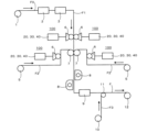
図1は、本実施形態に係る偏光フィルムの製造方法を適用する偏光フィルムの製造装置の概略構成例を模式的に示す図である。図1に示す矢符は、各フィルムの搬送方向を意味する。
本実施形態に係る偏光フィルムの製造装置は、接着剤塗工装置100と、活性エネルギー線照射装置8と、を備える他、一般的な偏光フィルムの製造装置が備える従来公知の各種構成要素を備えている。
なお、本発明に係る偏光フィルムの製造装置は、偏光子F1を製造した後、その偏光子F1に保護フィルムF2を連続的に接着する形式でもよく、或いは、偏光子F1を別途準備しておき、その偏光子F1に保護フィルムF2を接着する形式でもよい。前者の形式は、偏光子F1の製造から保護フィルムF2を接着して偏光フィルムFを得るまでの一連の工程を1つの製造ライン上で行う形式であり、後者の形式は、偏光子F1の製造を1つの製造ライン上で行い、その偏光子F1に保護フィルムF2を接着して偏光フィルムFを得る工程を別の製造ライン上で行う形式である。
図1に示す製造装置は、偏光子F1の製造から少なくとも保護フィルムF2を接着して偏光フィルムFを得るまでの一連の工程を1つの製造ライン上で行うロールツーロール形式である。
1 is a schematic diagram showing an example of the schematic configuration of a polarizing film manufacturing apparatus to which the polarizing film manufacturing method according to the present embodiment is applied. The arrows shown in FIG. 1 indicate the transport direction of each film.
The polarized film manufacturing apparatus according to this embodiment includes an
The polarizing film manufacturing apparatus according to the present invention may be of a type in which a polarizer F1 is manufactured and then a protective film F2 is continuously bonded to the polarizer F1, or a polarizer F1 is separately prepared and then a protective film F2 is bonded to the polarizer F1. The former type is a type in which a series of steps from manufacturing the polarizer F1 to bonding the protective film F2 to obtain a polarizing film F are performed on one manufacturing line, while the latter type is a type in which the polarizer F1 is manufactured on one manufacturing line and the step of bonding the protective film F2 to the polarizer F1 to obtain a polarizing film F is performed on another manufacturing line.
The manufacturing apparatus shown in FIG. 1 is of a roll-to-roll type, in which a series of steps from the manufacture of a polarizer F1 to the bonding of at least a protective film F2 to obtain a polarizing film F are carried out on a single manufacturing line.
図1に示す製造設備を用いて偏光フィルムFを製造するにあたっては、まず、繰出ローラ1に巻回された原反フィルムF0を繰り出し、処理槽2(例えば、原反フィルムF0の搬送方向上流側から順に、膨潤処理槽、染色処理槽、架橋処理槽、延伸処理槽、洗浄処理槽から構成される)内の処理浴に浸漬して、ヨウ素や二色性染料等の二色性物質で染色すると共に一軸延伸する。次いで、オーブン3で乾燥させることで、偏光子F1を得る。偏光子F1は、特定の1つの方向のみに振動する光(偏光)を透過し、それ以外の方向に振動する光を遮断する性質を有する光学素子である。本実施形態の偏光子F1は、柔軟なフィルム状である。
When manufacturing polarizing film F using the manufacturing equipment shown in FIG. 1, first, raw film F0 wound around a pay-out
原反フィルムF0は、長尺帯状である。本明細書において、長尺帯状は、長手方向の長さが短手方向(長手方向と直交する方向)の長さよりも十分に大きい長方形状を意味する。長尺帯状の長手方向の長さは、例えば、10m以上であり、好ましくは50m以上である。
原反フィルムF0としては、特に限定されないが、二色性物質による染色性に優れていることから、好ましくは、親水性ポリマーフィルム(例えば、ポリビニルアルコール系フィルムなど)を含むフィルムが用いられ、より好ましくは、親水性ポリマーフィルムが用いられる。親水性ポリマーフィルムを含むフィルムとしては、親水性ポリマーフィルムと非親水性ポリマーフィルムとが積層されたフィルムが挙げられる。この場合、非親水性ポリマーフィルムの表面及び/又は裏面に親水性ポリマーフィルムが積層されていることが好ましい。この場合、非親水性ポリマーフィルムの表面及び/又は裏面に積層される親水性ポリマーフィルムは、厚み数μm程度の薄い膜状であってもよい。
The raw film F0 is a long strip. In this specification, the long strip means a rectangular shape whose longitudinal length is sufficiently longer than its transverse length (the direction perpendicular to the longitudinal direction). The longitudinal length of the long strip is, for example, 10 m or more, and preferably 50 m or more.
The raw film F0 is not particularly limited, but is preferably a film containing a hydrophilic polymer film (e.g., a polyvinyl alcohol-based film, etc.) because of its excellent dyeability with a dichroic substance, and more preferably a hydrophilic polymer film. An example of a film containing a hydrophilic polymer film is a film in which a hydrophilic polymer film and a non-hydrophilic polymer film are laminated. In this case, it is preferable that the hydrophilic polymer film is laminated on the front and/or back surface of the non-hydrophilic polymer film. In this case, the hydrophilic polymer film laminated on the front and/or back surface of the non-hydrophilic polymer film may be a thin film having a thickness of about several μm.
親水性ポリマーフィルムとしては、特に限定されず、従来公知のフィルムを使用できる。具体的には、親水性ポリマーフィルムとしては、例えば、ポリビニルアルコール(PVA)系フィルム、部分ホルマール化PVA系フィルム、ポリエチレンテレフタレート(PET)フィルム、エチレン・酢酸ビニル共重合体系フィルム、これらの部分ケン化フィルムなどが挙げられる。また、これらの他にも、PVAの脱水処理物やポリ塩化ビニルの脱塩酸処理物などのポリエン配向フィルム、延伸配向されたポリビニレン系フィルムなども使用できる。これらの中でも、特に二色性物質による染色性に優れることから、PVA系ポリマーフィルムが好ましい。
PVA系ポリマーフィルムの原料ポリマーとしては、例えば、酢酸ビニルを重合した後にケン化したポリマー、酢酸ビニルに対して少量の不飽和カルボン酸や不飽和スルホン酸等の共重合可能なモノマーを共重合したポリマー、などが挙げられる。PVA系ポリマーの重合度は、特に限定されないが、水に対する溶解度の点等から、500~10000が好ましく、より好ましくは、1000~6000である。また、PVA系ポリマーのケン化度は、75モル%以上が好ましく、より好ましくは、98モル%~100モル%である。
未処理の原反フィルムF0の厚みは、特に限定されないが、例えば、15μm~110μmである。
The hydrophilic polymer film is not particularly limited, and a conventionally known film can be used. Specifically, examples of the hydrophilic polymer film include polyvinyl alcohol (PVA)-based films, partially formalized PVA-based films, polyethylene terephthalate (PET) films, ethylene-vinyl acetate copolymer-based films, and partially saponified films thereof. In addition to these, polyene-oriented films such as dehydrated PVA and dehydrochlorinated polyvinyl chloride, and stretch-oriented polyvinylene-based films can also be used. Among these, PVA-based polymer films are preferred because they are particularly excellent in dyeability with dichroic substances.
Examples of raw material polymers for PVA-based polymer films include polymers obtained by polymerizing vinyl acetate and then saponifying it, polymers obtained by copolymerizing vinyl acetate with a small amount of a copolymerizable monomer such as an unsaturated carboxylic acid or an unsaturated sulfonic acid, etc. The degree of polymerization of the PVA-based polymer is not particularly limited, but is preferably 500 to 10,000, and more preferably 1,000 to 6,000, in terms of solubility in water, etc. The degree of saponification of the PVA-based polymer is preferably 75 mol% or more, and more preferably 98 mol% to 100 mol%.
The thickness of the untreated raw film F0 is not particularly limited, but is, for example, 15 μm to 110 μm.
処理槽2が、原反フィルムF0の搬送方向上流側から順に、膨潤処理槽、染色処理槽、架橋処理槽、延伸処理槽、洗浄処理槽から構成される場合(図示せず)、各槽は、例えば、以下に述べる構成を有する。When the
<膨潤処理槽>
膨潤処理槽は、膨潤処理液が収容された処理槽である。膨潤処理液は、原反フィルムF0を膨潤させる。膨潤処理液としては、例えば、水を使用することができる。さらに、水に、グリセリンやヨウ化カリウムなどのヨウ素化合物を適量加えた水を膨潤処理液としてもよい。グリセリンを添加する場合、その濃度は5重量%以下が好ましく、ヨウ化カリウムなどのヨウ素化合物を添加する場合、その濃度は10重量%以下が好ましい。
<Swelling treatment tank>
The swelling treatment tank is a treatment tank containing a swelling treatment liquid. The swelling treatment liquid swells the raw film F0. For example, water can be used as the swelling treatment liquid. Furthermore, water to which an appropriate amount of an iodine compound such as glycerin or potassium iodide is added may be used as the swelling treatment liquid. When glycerin is added, the concentration is preferably 5% by weight or less, and when an iodine compound such as potassium iodide is added, the concentration is preferably 10% by weight or less.
<染色処理槽>
染色処理槽は、染色処理液が収容された処理槽である。染色処理液は、原反フィルムF0を染色する。染色処理液としては、有効成分として二色性物質を含む溶液が挙げられる。二色性物質としては、ヨウ素、有機染料などが挙げられる。好ましくは、染色処理液として、ヨウ素を溶媒に溶解させた溶液を使用できる。溶媒としては、水が一般的に使用されるが、水と相溶性のある有機溶媒が更に添加されてもよい。染色処理液中のヨウ素の濃度としては、特に限定されないが、0.01重量%~10重量%であることが好ましく、0.02重量%~7重量%の範囲がより好ましく、0.025重量%~5重量%であることがさらに好ましい。染色効率をより一層向上させるために、必要に応じて、染色処理液にヨウ素化合物を添加してもよい。ヨウ素化合物は、分子内にヨウ素とヨウ素以外の元素とを含む化合物であり、例えば、ヨウ化カリウム、ヨウ化リチウム、ヨウ化ナトリウム、ヨウ化亜鉛、ヨウ化アルミニウム、ヨウ化鉛、ヨウ化銅、ヨウ化バリウム、ヨウ化カルシウム、ヨウ化錫、ヨウ化チタンなどが挙げられる。
<Dyeing treatment tank>
The dyeing treatment tank is a treatment tank containing a dyeing treatment liquid. The dyeing treatment liquid dyes the raw film F0. The dyeing treatment liquid may be a solution containing a dichroic substance as an active ingredient. Examples of the dichroic substance include iodine and organic dyes. Preferably, a solution in which iodine is dissolved in a solvent may be used as the dyeing treatment liquid. Water is generally used as the solvent, but an organic solvent compatible with water may be further added. The concentration of iodine in the dyeing treatment liquid is not particularly limited, but is preferably 0.01% by weight to 10% by weight, more preferably 0.02% by weight to 7% by weight, and even more preferably 0.025% by weight to 5% by weight. In order to further improve the dyeing efficiency, an iodine compound may be added to the dyeing treatment liquid as necessary. An iodine compound is a compound that contains iodine and an element other than iodine in the molecule, and examples thereof include potassium iodide, lithium iodide, sodium iodide, zinc iodide, aluminum iodide, lead iodide, copper iodide, barium iodide, calcium iodide, tin iodide, and titanium iodide.
<架橋処理槽>
架橋処理槽は、架橋処理液が収容された処理槽である。架橋処理液は、染色された原反フィルムF0を架橋する。架橋処理液としては、有効成分としてホウ素化合物を含む溶液を使用できる。例えば、架橋処理液としては、ホウ素化合物を溶媒に溶解させた溶液が使用できる。溶媒としては、水が一般的に使用されるが、水と相溶性のある有機溶媒が更に添加されてもよい。ホウ素化合物としては、ホウ酸、ホウ砂などが挙げられる。架橋処理液中のホウ素化合物の濃度としては、特に限定されないが、1重量%~10重量%であることが好ましく、2重量%~7重量%がより好ましく、2重量%~6重量%であることがさらに好ましい。さらに、均一な光学特性を有する偏光子が得られることから、必要に応じて、架橋処理液にヨウ素化合物を添加してもよい。
<Crosslinking treatment tank>
The crosslinking treatment tank is a treatment tank containing a crosslinking treatment liquid. The crosslinking treatment liquid crosslinks the dyed raw film F0. As the crosslinking treatment liquid, a solution containing a boron compound as an active ingredient can be used. For example, as the crosslinking treatment liquid, a solution in which a boron compound is dissolved in a solvent can be used. As the solvent, water is generally used, but an organic solvent compatible with water may be further added. Examples of the boron compound include boric acid and borax. The concentration of the boron compound in the crosslinking treatment liquid is not particularly limited, but is preferably 1% by weight to 10% by weight, more preferably 2% by weight to 7% by weight, and even more preferably 2% by weight to 6% by weight. Furthermore, since a polarizer having uniform optical properties can be obtained, an iodine compound may be added to the crosslinking treatment liquid as necessary.
<延伸処理槽>
延伸処理槽は、延伸処理液が収容された処理槽である。
延伸処理液は、特に限定されないが、例えば、有効成分としてホウ素化合物を含む溶液を使用できる。延伸処理液としては、例えば、ホウ素化合物、及び必要に応じて、各種金属塩、亜鉛化合物などを溶媒に溶解させた溶液が使用できる。溶媒としては、水が一般的に使用されるが、水と相溶性のある有機溶媒が更に添加されてもよい。延伸処理液中のホウ素化合物の濃度としては、特に限定されないが、1重量%~10重量%であることが好ましく、2重量%~7重量%がより好ましい。フィルムに吸着させたヨウ素の溶出を抑制する観点から、必要に応じて、延伸処理液に、ヨウ素化合物を添加してもよい。
<Stretching tank>
The stretching treatment tank is a treatment tank that contains a stretching treatment solution.
The stretching treatment liquid is not particularly limited, but for example, a solution containing a boron compound as an active ingredient can be used. As the stretching treatment liquid, for example, a solution in which a boron compound and, if necessary, various metal salts, zinc compounds, etc. are dissolved in a solvent can be used. As the solvent, water is generally used, but an organic solvent compatible with water may be further added. The concentration of the boron compound in the stretching treatment liquid is not particularly limited, but is preferably 1% by weight to 10% by weight, more preferably 2% by weight to 7% by weight. From the viewpoint of suppressing the elution of iodine adsorbed to the film, an iodine compound may be added to the stretching treatment liquid as necessary.
<洗浄処理槽>
洗浄処理槽は、洗浄処理液が収容された処理槽である。洗浄処理液は、延伸後の原反フィルムF0を洗浄する。洗浄処理液は、原反フィルムF0に付着した染色処理液や架橋処理液などの処理液を洗浄するための処理液である。洗浄処理液としては、代表的には、イオン交換水、蒸留水、純水などの水が用いられる。
<Cleaning treatment tank>
The cleaning treatment tank is a treatment tank that contains a cleaning treatment liquid. The cleaning treatment liquid cleans the raw film F0 after stretching. The cleaning treatment liquid is a treatment liquid for cleaning treatment liquids such as dyeing treatment liquid and crosslinking treatment liquid that are attached to the raw film F0. As the cleaning treatment liquid, water such as ion-exchanged water, distilled water, and pure water is typically used.
オーブン3は、以上に説明した処理槽2を構成する洗浄処理槽の下流側に設けられている。オーブン3は、処理後のフィルムを乾燥するために設けられている。
なお、以上に説明した例では、処理槽2は、膨潤処理槽、染色処理槽、架橋処理槽、延伸処理槽及び洗浄処理槽を有するが、これらのうちの1つ又は2つの処理槽を省略してもよい。他方、処理槽2は、調整処理槽(図示せず)を更に有していてもよい。調整処理槽は、調整処理液が収容された処理槽である。この調整処理槽は、架橋処理槽と延伸処理槽との間、又は、延伸処理槽と洗浄処理槽との間に設けられる。調整処理液は、フィルムの色相調整などのための溶液であり、有効成分としてヨウ素化合物を含む溶液を使用できる。
洗浄後の原反フィルムF0をオーブン3で乾燥させて得られるフィルムが、偏光子F1である。
The
In the above-described example, the
The washed original film F0 was dried in an
次いで、図1に示すように、偏光子F1の両面に接着剤塗工装置100で活性エネルギー線硬化型接着剤を塗工する(本発明の接着剤塗工工程に相当)。また、繰出ローラ5から繰り出された保護フィルムF2の片面に接着剤塗工装置100で活性エネルギー線硬化型接着剤を塗工する。そして、貼り合わせローラ7によって、接着剤が塗工された保護フィルムF2を、接着剤が塗工された偏光子F1の両面に貼り合わせる。
接着剤の塗工厚みは、特に限定されないが、あまりに小さいと、フィルムの接着強度が低下し、あまりに大きいと、偏光フィルムFの厚みが相対的に大きくなりすぎる。かかる観点から、偏光子F1及び保護フィルムF2への接着剤の塗工厚みは、それぞれ独立して、0.1μm~5μmであることが好ましい。
また、塗工開始時の接着剤の粘度は、特に限定されないが、あまりに小さい又は大きいと、塗工開始時から接着剤の接着性の低下を生じる。かかる観点から、接着剤は、塗工開始時の25℃での粘度が1mPa・s~100mPa・sに調整されていることが好ましく、塗工開始時の25℃での粘度が10mPa・s~50mPa・sに調整されていることがより好ましく、15mPa・s~45mPa・sに調整されていることが特に好ましい。
接着剤塗工装置100の具体的な構成や、接着剤塗工装置100で塗工する接着剤の種類については、後述する。
1, an active energy ray curable adhesive is applied to both sides of the polarizer F1 by an adhesive applicator 100 (corresponding to the adhesive application step of the present invention). Also, an active energy ray curable adhesive is applied to one side of the protective film F2 fed from a
The coating thickness of the adhesive is not particularly limited, but if it is too small, the adhesive strength of the film decreases, and if it is too large, the thickness of the polarizing film F becomes relatively too large. From this viewpoint, it is preferable that the coating thickness of the adhesive on the polarizer F1 and the protective film F2 is each independently 0.1 μm to 5 μm.
In addition, the viscosity of the adhesive at the start of coating is not particularly limited, but if it is too low or high, the adhesiveness of the adhesive will decrease from the start of coating. From this viewpoint, the viscosity of the adhesive at 25°C at the start of coating is preferably adjusted to 1 mPa·s to 100 mPa·s, more preferably 10 mPa·s to 50 mPa·s, and particularly preferably 15 mPa·s to 45 mPa·s.
The specific configuration of the
保護フィルムF2は、長尺帯状である。また、保護フィルムF2は、偏光子F1よりも親水性が低い(疎水性を有する)フィルムである。保護フィルムF2としては、透明性、機械的強度、熱安定性、水分遮断性、等方性などに優れるものが好ましい。例えば、ポリエチレンテレフタレートやポリエチレンナフタレートなどのポリエステル系ポリマー、ジアセチルセルロースやトリアセチルセルロースなどのセルロース系ポリマー、ポリメチルメタクリレートなどのアクリル系ポリマー、ポリスチレンやアクリロニトリル・スチレン共重合体(AS樹脂)などのスチレン系ポリマー、ポリカーボネート系ポリマーなどが挙げられる。また、ポリエチレン、ポリプロピレン、シクロ系又はノルボルネン構造を有するポリオレフィン、エチレン・プロピレン共重合体の如きポリオレフィン系ポリマー、塩化ビニル系ポリマー、ナイロンや芳香族ポリアミドなどのアミド系ポリマー、イミド系ポリマー、スルホン系ポリマー、ポリエーテルスルホン系ポリマー、ポリエーテルエーテルケトン系ポリマー、ポリフェニレンスルフィド系ポリマー、ビニルアルコール系ポリマー、塩化ビニリデン系ポリマー、ビニルブチラール系ポリマー、アリレート系ポリマー、ポリオキシメチレン系ポリマー、エポキシ系ポリマー、又は上記ポリマーのブレンド物なども保護フィルムF2を形成するポリマーの例として挙げられる。保護フィルムF2中には任意の適切な添加剤が1種類以上含まれていてもよい。添加剤としては、例えば、紫外線吸収剤、酸化防止剤、滑剤、可塑剤、離型剤、着色防止剤、難燃剤、核剤、帯電防止剤、顔料、着色剤などが挙げられる。保護フィルムF2中の上記熱可塑性樹脂の含有量は、好ましくは50~100重量%、より好ましくは50~99重量%、さらに好ましくは60~98重量%、特に好ましくは70~97重量%である。保護フィルムF2中の上記熱可塑性樹脂の含有量が50重量%以下の場合、熱可塑性樹脂が本来有する高透明性などが十分に発現できないおそれがある。The protective film F2 is in the form of a long strip. The protective film F2 is a film that is less hydrophilic (has hydrophobicity) than the polarizer F1. The protective film F2 is preferably excellent in transparency, mechanical strength, thermal stability, moisture blocking properties, isotropy, etc. Examples of the protective film F2 include polyester-based polymers such as polyethylene terephthalate and polyethylene naphthalate, cellulose-based polymers such as diacetyl cellulose and triacetyl cellulose, acrylic polymers such as polymethyl methacrylate, styrene-based polymers such as polystyrene and acrylonitrile-styrene copolymer (AS resin), polycarbonate-based polymers, etc. Examples of the polymer forming the protective film F2 include polyethylene, polypropylene, polyolefins having a cyclo- or norbornene structure, polyolefin-based polymers such as ethylene-propylene copolymers, vinyl chloride-based polymers, amide-based polymers such as nylon and aromatic polyamides, imide-based polymers, sulfone-based polymers, polyethersulfone-based polymers, polyetheretherketone-based polymers, polyphenylene sulfide-based polymers, vinyl alcohol-based polymers, vinylidene chloride-based polymers, vinyl butyral-based polymers, arylate-based polymers, polyoxymethylene-based polymers, epoxy-based polymers, and blends of the above polymers. The protective film F2 may contain one or more of any suitable additives. Examples of the additives include ultraviolet absorbers, antioxidants, lubricants, plasticizers, release agents, coloring inhibitors, flame retardants, nucleating agents, antistatic agents, pigments, and colorants. The content of the thermoplastic resin in the protective film F2 is preferably 50 to 100% by weight, more preferably 50 to 99% by weight, even more preferably 60 to 98% by weight, and particularly preferably 70 to 97% by weight. If the content of the thermoplastic resin in the protective film F2 is 50% by weight or less, the inherent high transparency of the thermoplastic resin may not be fully exhibited.
また、保護フィルムF2としては、特開2001-343529号公報に記載のポリマーフィルム、例えば、(A)側鎖に置換及び/又は非置換イミド基を有する熱可塑性樹脂と、側鎖に置換及び/又は非置換フェニル並びにニトリル基を有する熱可塑性樹脂とを含有する樹脂組成物が挙げられる。具体例としては、イソブチレンとN-メチルマレイミドからなる交互共重合体とアクリロニトリル・スチレン共重合体とを含有する樹脂組成物のフィルムが挙げられる。フィルムとしては、樹脂組成物の混合押出品などからなるフィルムを用いることができる。これらのフィルムは位相差が小さく、光弾性係数が小さいため偏光フィルムFの歪みによるムラなどの不具合を解消することができ、また透湿度が小さいため、加湿耐久性に優れる。 In addition, examples of the protective film F2 include the polymer film described in JP-A-2001-343529, for example, a resin composition containing (A) a thermoplastic resin having a substituted and/or unsubstituted imide group in the side chain and a thermoplastic resin having a substituted and/or unsubstituted phenyl and nitrile group in the side chain. A specific example is a film of a resin composition containing an alternating copolymer of isobutylene and N-methylmaleimide and an acrylonitrile-styrene copolymer. As the film, a film made of a mixed extrusion product of the resin composition can be used. These films have a small phase difference and a small photoelastic coefficient, so they can eliminate problems such as unevenness caused by distortion of the polarizing film F, and have a small moisture permeability, so they have excellent moisture durability.
次いで、図1に示すように、活性エネルギー線照射装置8から偏光子F1及び保護フィルムF2間の接着剤に活性エネルギー線を照射して硬化させた後、オーブン9で乾燥させる。活性エネルギー線は、活性エネルギー線硬化型接着剤の硬化性に応じて適宜選択される。活性エネルギー線としては、電子線、紫外線、可視光線などが挙げられる。最後に、両面に保護フィルムF2が貼り合わせられた偏光子F1の片面に、繰出ローラ10から繰り出された長尺帯状の表面保護フィルムF3を貼り合わせローラ11によって貼り合わせることで、長尺帯状の偏光フィルムFが得られる。得られた偏光フィルムFは、巻取ローラ12で巻き取られる。
偏光子F1と保護フィルムF2とを接着剤を介して貼り合わせ、接着剤に活性エネルギー線を照射して接着剤を硬化させることで偏光フィルムFを作製する工程が、本発明の光学積層体作製工程に相当する。
Next, as shown in FIG. 1, the adhesive between the polarizer F1 and the protective film F2 is irradiated with active energy rays from an active energy
The process of producing a polarizing film F by bonding a polarizer F1 and a protective film F2 via an adhesive and curing the adhesive by irradiating the adhesive with active energy rays corresponds to the optical laminate production process of the present invention.
なお、図1に示す例では、偏光子F1及び保護フィルムF2の双方に活性エネルギー線硬化型接着剤を塗工しているが、偏光子F1の両面にのみ接着剤を塗工することも可能である。この場合、図1に示す計4台の接着剤塗工装置100のうち、図1の下側(フィルムの搬送方向下流側)2台の接着剤塗工装置100は不要である。また、保護フィルムF2の片面にのみ接着剤を塗工することも可能である。この場合、図1に示す計4台の接着剤塗工装置100のうち、図1の上側(フィルムの搬送方向上流側)2台の接着剤塗工装置100は不要である。さらに、図1に示す例では、偏光子F1の両面に保護フィルムF2を貼り合わせているため、接着剤塗工装置100を図1の左右に一対配置し、活性エネルギー線照射装置8を左右に一対配置しているが、偏光子F1の片面にのみ保護フィルムF2を貼り合わせる場合には、接着剤塗工装置100及び活性エネルギー線照射装置8は、図1の左右何れかに1台配置するだけでよい。In the example shown in FIG. 1, the active energy ray curable adhesive is applied to both the polarizer F1 and the protective film F2, but it is also possible to apply the adhesive only to both sides of the polarizer F1. In this case, of the total of four
図2は、接着剤塗工装置100の具体的な構成例を模式的に示す図である。図2は、各構成要素の内部を適宜透視した状態で図示している。
図2に示すように、本実施形態の接着剤塗工装置100は、接着剤adを偏光子F1又は保護フィルムF2(図2では図示省略)に塗工する塗工機6と、接着剤adを貯留し、塗工機6との間で接着剤adを循環させながら塗工機6に接着剤adを供給する第1タンク20と、接着剤adを密封して貯留し、第1タンク20に接着剤adを供給する、第1タンク20よりも接着剤adの貯留量が大きな第2タンク30と、第1タンク20内の接着剤adの貯留量が所定値以下となった場合に、第2タンク30から第1タンク20に接着剤adを供給させる制御装置40と、を備えている。
Fig. 2 is a diagram showing a schematic diagram of a specific configuration example of the
As shown in FIG. 2, the
塗工機6としては、グラビアコータが好適に用いられる。グラビアコータは、表面に複数のセル(供給された接着剤adが入る凹部)が形成されたグラビアロールを有し、このグラビアロール61が偏光子F1又は保護フィルムF2に接触することにより、セル内の接着剤adが偏光子F1又は保護フィルムF2の片面に転写される。このようにして、グラビアロールから偏光子F1又は保護フィルムF2の片面に、それぞれ接着剤adがベタ状に塗工される。A gravure coater is preferably used as the
本実施形態の接着剤塗工装置100は、供給管21、ポンプ22、屈折率計23及び排出管24を更に備えている。
第1タンク20内に貯留されている接着剤adは、供給管21に取り付けられたポンプ22によって、下端が第1タンク20内に挿入されて接着剤adに浸漬された供給管21を通じて吸い上げられ、塗工機6に供給される。供給管21には、屈折率計23が取り付けられており、供給管21中を流れる接着剤adの屈折率が屈折率計23によって連続的に測定される。屈折率計23としては、従来公知の屈折率計を種々適用可能であり、例えば、全反射臨界角からスネルの法則を用いて屈折率を導出する方法を測定原理とするATAGO社製のプロセス屈折計「PRM-100α」を用いることができる。
The
The adhesive ad stored in the
一方、塗工機6で偏光子F1又は保護フィルムF2に塗工されなかった接着剤adは、下端が第1タンク20内に挿入された排出管24を通じて第1タンク20内に戻る。
以上のようにして、接着剤adは、第1タンク20と塗工機6との間で循環しながら使用される。
On the other hand, the adhesive ad that has not been applied to the
In this manner, the adhesive ad is used while being circulated between the
本実施形態の接着剤塗工装置100は、袋体31、結束バンド32、第1供給管33、重り34、継手35、第2供給管36及び蓋体37を更に備えている。
第2タンク30内には、内部に接着剤adが収容されて上端部が結束バンド32で縛られた袋体31が収容されている。これにより、第2タンク30内には、接着剤adが密封されて貯留される。袋体31内には、ゴム製ホース等の可撓性を有する第1供給管33が挿入されている。第1供給管33の下端が袋体31の底面近傍に位置するように、第1供給管33の下端には重り34が取り付けられている。第1供給管33は、袋体31の上端部及び結束バンド32内を通り、その上端が継手35に接続されている。この継手35には、ゴム製ホース等の可撓性を有する第2供給管36も接続されており、継手35を介して、第1供給管33と第2供給管36とが連通している。第2タンク30内(袋体31内)に貯留されている接着剤adは、第2供給管36に取り付けられたポンプ42によって、第1供給管33の下端から、第1供給管33、継手35及び第2供給管36を通じて吸い上げられ、第2供給管36の下端から排出されて、第1タンク20に供給される。
The
The
第2タンク30内(袋体31内)の接着剤adの貯留量は、第1タンク20内の接着剤adの貯留量よりも大きい。例えば、第2タンク30内の接着剤adの貯留量が180リットルであるのに対し、第1タンク20内の接着剤adの貯留量は30リットル以下である。第1タンク20内の接着剤adの貯留量に対し、第2タンク30内の接着剤adの貯留量は、2~50倍程度であることが好ましい。The amount of adhesive ad stored in the second tank 30 (in the bag body 31) is greater than the amount of adhesive ad stored in the
なお、第2タンク30から第1タンク20に接着剤adを供給する際には、図2に示すように、第2タンク30の上端開口を閉塞するための蓋体37を開いて、継手35に第2供給管36を接続することになる。一方、第2タンク30内で接着剤adを調製する際には、継手35から第2供給管36を取り外し、蓋体37を閉じればよい。この際、蓋体37の下面に目止め(図示せず)を設け、継手35の第2供給管36との接続箇所にこの目止めで栓をすれば、第2タンク30内における接着剤adの密封状態を維持可能である。When supplying adhesive ad from the
本実施形態の制御装置40は、コンピュータやPLC(Programmable Logic Controller)から構成される制御装置本体41と、ポンプ42と、レベル計43と、を具備する。レベル計43としては、従来公知のレベル計(液面計)を種々適用可能であり、例えば、ガイドパルス方式を測定原理とするキーエンス社製のガイドパルス式レベルセンサ「FL-001」を用いることができる。
制御装置本体41には、レベル計43で測定した第1タンク20内に貯留されている接着剤adの液面高さ測定値が入力される。制御装置本体41は、入力された液面高さ測定値が予め設定したしきい値以下となった場合(すなわち、第1タンク20内の接着剤adの貯留量が所定値以下となった場合)に、ポンプ42に対し、ポンプ42を駆動する制御信号を送信する。これにより、ポンプ42が駆動し、第2タンク30内(袋体31内)に貯留されている接着剤adが、第1供給管33の下端から、第1供給管33、継手35及び第2供給管36を通じて吸い上げられ、第2供給管36の下端から排出されて、第1タンク20に供給される。
以上のようにして、制御装置40は、第1タンク20内の接着剤adの貯留量が所定値以下となった場合に、第2タンク30から第1タンク20に接着剤adを供給させる。
The
The control device
In this manner, when the amount of adhesive ad stored in the
以上に説明した構成を有する接着剤塗工装置100で塗工する接着剤adとしては、活性エネルギー線硬化型接着剤が用いられる。つまり、接着剤塗工装置100の第2タンク30内には、未硬化の活性エネルギー線硬化型接着剤が調製されて貯留されている。
活性エネルギー線硬化型接着剤としては、従来公知のものを使用できる。活性エネルギー線硬化型接着剤は、一般に、活性エネルギー線硬化性成分及び重合開始剤を含み、必要に応じて、各種の添加剤を含む。
活性エネルギー線硬化性成分は、電子線硬化性、紫外線硬化性、可視光線硬化性に大別できる。また、活性エネルギー線硬化性成分は、硬化のメカニズムの観点では、ラジカル重合性化合物とカチオン重合性化合物とに大別できる。
An active energy ray curable adhesive is used as the adhesive ad applied by the
As the active energy ray-curable adhesive, a conventionally known adhesive can be used. The active energy ray-curable adhesive generally contains an active energy ray-curable component and a polymerization initiator, and further contains various additives as necessary.
Active energy ray-curable components can be roughly divided into electron beam-curable, ultraviolet ray-curable, and visible light-curable components, and from the viewpoint of the curing mechanism, active energy ray-curable components can be roughly divided into radical polymerizable compounds and cationically polymerizable compounds.
ラジカル重合性化合物としては、(メタ)アクリロイル基、ビニル基などの炭素-炭素二重結合のラジカル重合性の官能基を有する化合物が挙げられる。また、単官能ラジカル重合性化合物又は二官能以上の多官能ラジカル重合性化合物のいずれも用いることができる。また、これらラジカル重合性化合物は、1種単独で又は2種以上を併用してもよい。ラジカル重合性化合物としては、(メタ)アクリロイル基を有する化合物が好ましく、例えば、(メタ)アクリルアミド基を有する(メタ)アクリルアミド誘導体、(メタ)アクリロイルオキシ基を有する(メタ)アクリレートなどが挙げられる。
活性エネルギー線硬化型接着剤としてラジカル重合性化合物を用いる場合の重合開始剤は、活性エネルギー線に応じて適宜に選択される。紫外線又は可視光線により接着剤を硬化させる場合には、紫外線開裂又は可視光線開裂の重合開始剤が用いられる。このような重合開始剤としては、例えば、ベンゾフェノン系化合物、芳香族ケトン化合物、アセトフェノン系化合物、芳香族ケタール系化合物、芳香族スルホニルクロリド系化合物、チオキサントン系化合物などが挙げられる。
Examples of the radical polymerizable compound include compounds having a radical polymerizable functional group of a carbon-carbon double bond, such as a (meth)acryloyl group or a vinyl group. In addition, either a monofunctional radical polymerizable compound or a bifunctional or higher polyfunctional radical polymerizable compound can be used. In addition, these radical polymerizable compounds may be used alone or in combination of two or more. As the radical polymerizable compound, a compound having a (meth)acryloyl group is preferable, and examples thereof include a (meth)acrylamide derivative having a (meth)acrylamide group and a (meth)acrylate having a (meth)acryloyloxy group.
When a radical polymerizable compound is used as the active energy ray curable adhesive, the polymerization initiator is appropriately selected according to the active energy ray. When the adhesive is cured by ultraviolet light or visible light, a polymerization initiator that is cleaved by ultraviolet light or visible light is used. Examples of such polymerization initiators include benzophenone-based compounds, aromatic ketone compounds, acetophenone-based compounds, aromatic ketal-based compounds, aromatic sulfonyl chloride-based compounds, and thioxanthone-based compounds.
カチオン重合性化合物としては、分子内にカチオン重合性官能基を1つ有する単官能カチオン重合性化合物、分子内にカチオン重合性官能基を2つ以上有する多官能カチオン重合性化合物などが挙げられる。カチオン重合性官能基としては、エポキシ基、オキセタニル基、オキセタン基、ビニルエーテル基、スピロオルトエステル基などが挙げられる。エポキシ基を有するカチオン重合性化合物としては、脂肪族エポキシ化合物、脂環式エポキシ化合物、芳香族エポキシ化合物などが挙げられる。オキセタニル基を有するカチオン重合性化合物としては、3-エチル-3-ヒドロキシメチルオキセタン、1,4-ビス[(3-エチル-3-オキセタニル)メトキシメチル]ベンゼン、3-エチル-3-(フェノキシメチル)オキセタンなどが挙げられる。ビニルエーテル基を有するカチオン重合性化合物としては、2-ヒドロキシエチルビニルエーテル、ジエチレングリコールモノビニルエーテル、4-ヒドロキシブチルビニルエーテルなどが挙げられる。
活性エネルギー線硬化型接着剤としてカチオン重合性化合物を用いる場合、カチオン重合開始剤が配合される。このカチオン重合開始剤は、可視光線、紫外線、電子線などの活性エネルギー線の照射によって、カチオン種又はルイス酸を発生し、カチオン重合性化合物のエポキシ基などと重合反応を開始する。カチオン重合開始剤としては、光酸発生剤と光塩基発生剤とを使用することができる。
Examples of the cationic polymerizable compound include a monofunctional cationic polymerizable compound having one cationic polymerizable functional group in the molecule, and a polyfunctional cationic polymerizable compound having two or more cationic polymerizable functional groups in the molecule. Examples of the cationic polymerizable functional group include an epoxy group, an oxetanyl group, an oxetane group, a vinyl ether group, and a spiro orthoester group. Examples of the cationic polymerizable compound having an epoxy group include an aliphatic epoxy compound, an alicyclic epoxy compound, and an aromatic epoxy compound. Examples of the cationic polymerizable compound having an oxetanyl group include 3-ethyl-3-hydroxymethyloxetane, 1,4-bis[(3-ethyl-3-oxetanyl)methoxymethyl]benzene, and 3-ethyl-3-(phenoxymethyl)oxetane. Examples of the cationic polymerizable compound having a vinyl ether group include 2-hydroxyethyl vinyl ether, diethylene glycol monovinyl ether, and 4-hydroxybutyl vinyl ether.
When a cationic polymerizable compound is used as the active energy ray curable adhesive, a cationic polymerization initiator is blended. This cationic polymerization initiator generates cationic species or Lewis acid by irradiation with active energy rays such as visible light, ultraviolet light, and electron beams, and initiates a polymerization reaction with the epoxy group of the cationic polymerizable compound. As the cationic polymerization initiator, a photoacid generator and a photobase generator can be used.
本発明においては、380nm~450nmの可視光線を含む光で硬化する活性エネルギー線硬化型接着剤を用いることもできる。この場合、ラジカル重合性化合物と重合開始剤とを含む活性エネルギー線硬化型接着剤を用いることが好ましい。
このような活性エネルギー線硬化型接着剤は、例えば、特開2018-092186号公報に開示されており、本発明の活性エネルギー線硬化型接着剤として、上記公報に記載の活性エネルギー線硬化型接着剤を用いることができる。本明細書においては、紙面の都合上、上記公報の記載を転記することを省略するが、上記公報の接着剤に関する記載を本明細書にそのまま取り込めるものとする。
In the present invention, an active energy ray-curable adhesive that is cured by light containing visible light of 380 nm to 450 nm can also be used. In this case, it is preferable to use an active energy ray-curable adhesive containing a radical polymerizable compound and a polymerization initiator.
Such an active energy ray curable adhesive is disclosed, for example, in JP 2018-092186 A, and the active energy ray curable adhesive described in the above publication can be used as the active energy ray curable adhesive of the present invention. In this specification, due to space limitations, the description of the above publication is omitted, but the description of the adhesive in the above publication is incorporated into this specification as it is.
また、本発明においては、接着剤adとして、水酸基を含有する活性エネルギー線硬化型接着剤を用いることもできる。このような活性エネルギー線硬化型接着剤としては、例えば、特許文献1の段落0152及び表1に記載の実施例1の接着剤を用いることができる。本明細書においては、紙面の都合上、上記特許文献1の記載を転記することを省略するが、上記特許文献1の接着剤に関する記載を本明細書にそのまま取り込めるものとする。In addition, in the present invention, an active energy ray curable adhesive containing a hydroxyl group can also be used as the adhesive ad. For example, the adhesive of Example 1 described in paragraph 0152 and Table 1 of
また、本発明においては、接着剤adとして、SP値が29.0(MJ/m3)1/2以上32.0(MJ/m3)1/2以下であるラジカル重合性化合物、又は、21.0(MJ/m3)1/2以上23.0(MJ/m3)1/2以下であるラジカル重合性化合物を含有する活性エネルギー線硬化型接着剤を用いることもできる。このような活性エネルギー線硬化型接着剤としては、例えば、特許文献2の段落0015等に記載のラジカル重合性化合物(A)やラジカル重合性化合物(C)を含有する活性エネルギー線硬化型接着剤を用いることができる。本明細書においては、紙面の都合上、上記特許文献2の記載を転記することを省略するが、上記特許文献2の接着剤に関する記載を本明細書にそのまま取り込めるものとする。
In the present invention, the adhesive ad may be an active energy ray curable adhesive containing a radical polymerizable compound having an SP value of 29.0 (MJ / m 3 ) 1/2 or more and 32.0 (MJ/m 3 ) 1/2 or less. The active energy ray curable adhesive may be, for example, an active energy ray curable adhesive containing a radical polymerizable compound (A) or a radical polymerizable compound (C ) described in paragraph 0015 of
また、本発明においては、接着剤adとして、水を含有する活性エネルギー線硬化型接着剤を用いることもできる。このような活性エネルギー線硬化型接着剤としては、例えば、従来公知の活性エネルギー線硬化型接着剤と特許文献3の表3に記載の実施例16の接着剤(易接着組成物)との組み合わせを用いることができる。本明細書においては、紙面の都合上、上記特許文献3の記載を転記することを省略するが、上記特許文献3の接着剤に関する記載を本明細書にそのまま取り込めるものとする。In addition, in the present invention, an active energy ray curable adhesive containing water can also be used as the adhesive ad. For example, a combination of a conventionally known active energy ray curable adhesive and the adhesive of Example 16 (easy-adhesion composition) described in Table 3 of
さらに、本発明においては、接着剤adとして、金属アルコキシド及び金属キレートからなる群より選択される少なくとも1種の有機金属化合物を含有する活性エネルギー線硬化型接着剤を用いることもできる。このような活性エネルギー線硬化型接着剤としては、例えば、特許文献1の段落0152及び表1に記載の実施例1の接着剤を用いることができる。Furthermore, in the present invention, an active energy ray curable adhesive containing at least one organometallic compound selected from the group consisting of metal alkoxides and metal chelates can be used as the adhesive ad. As such an active energy ray curable adhesive, for example, the adhesive of Example 1 described in paragraph 0152 and Table 1 of
以上に説明した本実施形態に係る偏光フィルムFの製造方法によれば、第1タンク20内に貯留されている接着剤adが偏光子F1及び保護フィルムF2に塗工されて、第1タンク20内の接着剤adの貯留量が所定値以下となった場合に、第2タンク30から第1タンク20に接着剤adが供給されることになる。第2タンク30では、接着剤adが密封されて貯留されているため、雰囲気中の水分を吸収し難く、溶媒成分も揮発し難い。また、塗工機6で塗工されなかった接着剤adは、第2タンク30には戻らず第1タンク20に戻るため、第2タンク30内には、第1タンク20と塗工機6との間の循環使用によって雰囲気中の水分を吸収した接着剤adや、溶媒成分の揮発した接着剤adが混入しない。このため、新品に近い接着剤adが第2タンク30から第1タンク20に供給され、この新品に近い接着剤adが第1タンク20と塗工機6との間で新たに循環することになる。第2タンク30における接着剤adの貯留量は第1タンク20よりも大きいため、第2タンク30内の接着剤が無くなるまで、第2タンク30内の接着剤adを交換することなく、長期に亘って使用可能である。
したがい、本実施形態に係る偏光フィルムFの製造方法によれば、接着剤adのランニングコストを抑制し且つ偏光フィルムFの製造効率を損なうことなく、偏光フィルムFにおける偏光子F1と保護フィルムF2との間の良好な接着性を維持することが可能である。
According to the manufacturing method of the polarizing film F according to the present embodiment described above, when the adhesive ad stored in the
Therefore, according to the manufacturing method of the polarizing film F of this embodiment, it is possible to maintain good adhesion between the polarizer F1 and the protective film F2 in the polarizing film F while reducing the running costs of the adhesive ad and without compromising the manufacturing efficiency of the polarizing film F.
図3は、図2に示す屈折率計23で測定した接着剤adの屈折率の変化と、測定した屈折率から演算した接着剤adの水分率の変化との一例を示す図である。なお、図3において、屈折率についての縦軸(図3の左側の縦軸)は、初期の屈折率からの変化量で表している。
接着剤adの屈折率と水分率とは、屈折率をX、水分率をYとすると、Y=aX+b(a、bは接着剤adに応じて決まる係数)で表される関係があり、この関係式を用いて、測定した屈折率から水分率を演算することが可能である。
接着剤adの屈折率(図3において実線で示す)及び水分率(図3において破線で示す)は、第1タンク20と塗工機6との間での接着剤adの循環を開始してから、「連続運転開始時点」(19時間経過後)までの間は、塗工機6から接着剤adを塗工せずに、第1タンク20と塗工機6との間で接着剤adを循環させた状態で測定・演算した。また、「連続運転開始時点」経過後は、第1タンク20と塗工機6との間で接着剤adを循環させながら、塗工機6から接着剤adを塗工した状態で測定・演算した。図3に白抜き矢符で示す時点は、ポンプ42を駆動して第2タンク30から第1タンク20に接着剤adを供給したタイミングを示す。
図3に示すように、時間の経過と共に、雰囲気中の水分を吸収することで、接着剤adの屈折率は低下(水分率は上昇)しているが、白抜き矢符のタイミングで第2タンク30から第1タンク20に新品に近い接着剤adが供給されることで、塗工される接着剤adの屈折率は上昇(水分率は低下)し、良好な接着性の維持が期待できることが分かる。
Fig. 3 is a diagram showing an example of the change in refractive index of the adhesive ad measured by the
The refractive index and moisture content of the adhesive ad have a relationship expressed by Y = aX + b (a and b are coefficients determined according to the adhesive ad), where X is the refractive index and Y is the moisture content. Using this relationship, it is possible to calculate the moisture content from the measured refractive index.
The refractive index (shown by a solid line in FIG. 3) and moisture content (shown by a dashed line in FIG. 3) of the adhesive ad were measured and calculated in a state in which the adhesive ad was circulated between the
As shown in Figure 3, over time, the refractive index of the adhesive ad decreases (the moisture content increases) as it absorbs moisture from the atmosphere. However, by supplying nearly new adhesive ad from the
以下、実施例及び比較例を説明し、本発明を更に詳述する。ただし、本発明は、下記実施例に限定されるものではない。The present invention will be described in more detail below with reference to examples and comparative examples. However, the present invention is not limited to the following examples.
[使用材料]
<活性エネルギー線硬化型接着剤A>
55重量%の1,9-ノナンジオールジアクリレート、10重量%のヒドロキシエチルアクリルアミド及び30重量%のアクリロイルモルフォリン(活性エネルギー線硬化性成分)と、3重量%のIRGACURE 907及び2重量%のKAYACURE DETX-S(重合開始剤)と、を混合し、3時間撹拌することにより、活性エネルギー線硬化型接着剤Aを得た。
この活性エネルギー線硬化型接着剤Aの塗工開始時の25℃における粘度は、20mPa・sであった。
[Materials used]
<Active energy ray curable adhesive A>
55% by weight of 1,9-nonanediol diacrylate, 10% by weight of hydroxyethyl acrylamide, and 30% by weight of acryloylmorpholine (active energy ray curable components) were mixed with 3% by weight of
The viscosity of this active energy ray-curable adhesive A at 25° C. at the start of coating was 20 mPa·s.
<活性エネルギー線硬化型接着剤B>
52重量%の1,9-ノナンジオールジアクリレート、10重量%のヒドロキシエチルアクリルアミド及び30重量%のアクリロイルモルフォリン、3重量部の3-アクリルアミドフェニルボロン酸(活性エネルギー線硬化性成分)と、3重量%のIRGACURE 907及び2重量%のKAYACURE DETX-S(重合開始剤)と、を混合し、3時間撹拌することにより、活性エネルギー線硬化型接着剤Bを得た。
この活性エネルギー線硬化型接着剤Bの塗工開始時の25℃における粘度は、22mPa・sであった。
<Active energy ray curable adhesive B>
52% by weight of 1,9-nonanediol diacrylate, 10% by weight of hydroxyethyl acrylamide, 30% by weight of acryloyl morpholine, 3 parts by weight of 3-acrylamidophenylboronic acid (active energy ray curable component), 3% by weight of
The viscosity of this active energy ray-curable adhesive B at 25° C. at the start of coating was 22 mPa·s.
<活性エネルギー線硬化型接着剤C>
53重量%の1,9-ノナンジオールジアクリレート、10重量%のヒドロキシエチルアクリルアミド及び30重量%のアクリロイルモルフォリン、1重量部の3-アクリルアミドフェニルボロン酸(活性エネルギー線硬化性成分)、1重量部のオルガチックスTA-30:テトラオクチルチタネートと、3重量%のIRGACURE 907及び2重量%のKAYACURE DETX-S(重合開始剤)と、を混合し、3時間撹拌することにより、活性エネルギー線硬化型接着剤Cを得た。
この活性エネルギー線硬化型接着剤Cの塗工開始時の25℃における粘度は、20mPa・sであった。
<Active energy ray curable adhesive C>
53% by weight of 1,9-nonanediol diacrylate, 10% by weight of hydroxyethyl acrylamide, 30% by weight of acryloyl morpholine, 1 part by weight of 3-acrylamidophenylboronic acid (active energy ray curable component), 1 part by weight of Orgatix TA-30: tetraoctyl titanate, 3% by weight of
The viscosity of this active energy ray-curable adhesive C at 25° C. at the start of coating was 20 mPa·s.
<活性エネルギー線硬化型接着剤D>
62重量%のグリセリントリアクリレート、10重量%の4-ヒドロキシブチルアクリレート、20重量%の3-エチル-3-{[(3-エチルオキセタン-3-イル)メトキシ]メチル}オキセタン、3重量%のIRGACURE 907及び2重量%のKAYACURE DETX-S(重合開始剤)、3重量%のCPI-100P(光酸発生剤)を混合し、3時間撹拌することにより、活性エネルギー線硬化型接着剤Dを得た。
この活性エネルギー線硬化型接着剤Dの塗工開始時の25℃における粘度は、35mPa・sであった。
なお、活性エネルギー線硬化型接着剤A~Dの塗工開始時の25℃における粘度は、E型粘度計を用いて測定した。
<Active energy ray curable adhesive D>
Active energy ray-curable adhesive D was obtained by mixing 62% by weight of glycerin triacrylate, 10% by weight of 4-hydroxybutyl acrylate, 20% by weight of 3-ethyl-3-{[(3-ethyloxetan-3-yl)methoxy]methyl}oxetane, 3% by weight of
The viscosity of this active energy ray-curable adhesive D at 25° C. at the start of coating was 35 mPa·s.
The viscosity at 25° C. at the start of coating of the active energy ray-curable adhesives A to D was measured using an E-type viscometer.
<偏光子X>
図1に示す繰出ローラ1、処理槽2及びオーブン3を備える既存の偏光子製造装置を用い、平均重合度2400、ケン化度99.9モル%の厚み45μmのポリビニルアルコールフィルムを、30℃の温水中に60秒間浸漬し膨潤させた。次いで、ヨウ素/ヨウ化カリウム(重量比=0.5/8)の濃度0.3%の水溶液に浸漬し、3.5倍まで延伸させながらフィルムを染色した。その後、65℃のホウ酸エステル水溶液中で、トータルの延伸倍率が6倍となるように延伸を行った。延伸後に、40℃のオーブンにて3分間乾燥させ、長尺帯状のポリビニルアルコール系偏光子(厚み18μm)Xを得た。
なお、偏光子Xに易接着処理を施す場合には、特許文献3の表3に記載の実施例16の易接着組成物を用いた。
<Polarizer X>
Using an existing polarizer manufacturing apparatus including a
When the easy-adhesion treatment was performed on the polarizer X, the easy-adhesion composition of Example 16 described in Table 3 of
<保護フィルムY、Z>
偏光子Xの一方の片面に貼り合わせる保護フィルムYとして、厚み52μmの環状ポリオレフィンフィルム(日本ゼオン(株)製)を用い、偏光子Xとの貼り合わせ面にコロナ処理等のドライ処理を施した。
偏光子Xの他方の片面に貼り合わせる保護フィルムZとして、厚み60μmのトリアセチルセルロースフィルム(富士フイルム(株)製)を用いた。
<Protective films Y and Z>
As the protective film Y to be attached to one side of the polarizer X, a cyclic polyolefin film (manufactured by Zeon Corporation) having a thickness of 52 μm was used, and the surface to be attached to the polarizer X was subjected to a dry treatment such as a corona treatment.
As the protective film Z to be attached to the other surface of the polarizer X, a triacetyl cellulose film having a thickness of 60 μm (manufactured by FUJIFILM Corporation) was used.
[実施例1]
偏光子Xと保護フィルムY、Zとを活性エネルギー線硬化型接着剤Aを用いて貼り合わせ、接着剤Aを硬化させることで偏光フィルムを作製した。偏光子Xには易接着処理を施さなかった。そして、初期の接着剤A(図3の「連続運転開始時点」相当の接着剤)を用いて作製した偏光フィルムに対して90度剥離試験を行い、偏光子Xと保護フィルムYとの間の剥離力、及び、偏光子Xと保護フィルムZとの間の剥離力を測定した。また、32時間連続運転後の接着剤Aを用いて作製した偏光フィルムに対して90度剥離試験を行い、偏光子Xと保護フィルムYとの間の剥離力、及び、偏光子Xと保護フィルムZとの間の剥離力を測定した。
[Example 1]
A polarizing film was produced by bonding the polarizer X and the protective films Y and Z together using an active energy ray curable adhesive A, and curing the adhesive A. The polarizer X was not subjected to an easy-adhesion treatment. Then, a 90-degree peel test was performed on the polarizing film produced using the initial adhesive A (the adhesive corresponding to the "start time of continuous operation" in FIG. 3), and the peel strength between the polarizer X and the protective film Y and the peel strength between the polarizer X and the protective film Z were measured. In addition, a 90-degree peel test was performed on the polarizing film produced using the adhesive A after 32 hours of continuous operation, and the peel strength between the polarizer X and the protective film Y and the peel strength between the polarizer X and the protective film Z were measured.
[実施例2]
活性エネルギー線硬化型接着剤Bを用いたこと以外は、実施例1と同様にして、偏光フィルムを作製し、剥離力を測定した。
[Example 2]
A polarizing film was produced and the peel strength was measured in the same manner as in Example 1, except that active energy ray-curable adhesive B was used.
[実施例3]
活性エネルギー線硬化型接着剤Cを用いたこと以外は、実施例1と同様にして、偏光フィルムを作製し、剥離力を測定した。
[Example 3]
A polarizing film was produced and the peel strength was measured in the same manner as in Example 1, except that active energy ray-curable adhesive C was used.
[実施例4]
活性エネルギー線硬化型接着剤Dを用い、偏光子Xに易接着処理を施したこと以外は、実施例1と同様にして、偏光フィルムを作製し、剥離力を測定した。
[Example 4]
A polarizing film was produced in the same manner as in Example 1, except that the active energy ray-curable adhesive D was used and the polarizer X was subjected to an easy-adhesion treatment, and the peel strength was measured.
[比較例1]
第2タンク30を密封せずに接着剤を貯留し、塗工機6で塗工されなかった接着剤を第1タンク20ではなく第2タンク30に戻した(すなわち、第2タンク30、第1タンク20及び塗工機6の間で接着剤を循環使用した)こと以外は、実施例1と同様にして、偏光フィルムを作製し、剥離力を測定した。
[Comparative Example 1]
A polarized film was produced and the peel strength was measured in the same manner as in Example 1, except that the
[比較例2]
第2タンク30を密封せずに接着剤を貯留し、塗工機6で塗工されなかった接着剤を第1タンク20ではなく第2タンク30に戻した(すなわち、第2タンク30、第1タンク20及び塗工機6の間で接着剤を循環使用した)こと以外は、実施例2と同様にして、偏光フィルムを作製し、剥離力を測定した。
[Comparative Example 2]
A polarized film was produced and the peel strength was measured in the same manner as in Example 2, except that the
[比較例3]
第2タンク30を密封せずに接着剤を貯留し、塗工機6で塗工されなかった接着剤を第1タンク20ではなく第2タンク30に戻した(すなわち、第2タンク30、第1タンク20及び塗工機6の間で接着剤を循環使用した)こと以外は、実施例3と同様にして、偏光フィルムを作製し、剥離力を測定した。
[Comparative Example 3]
A polarized film was produced and the peel strength was measured in the same manner as in Example 3, except that the
[比較例4]
第2タンク30を密封せずに接着剤を貯留し、塗工機6で塗工されなかった接着剤を第1タンク20ではなく第2タンク30に戻した(すなわち、第2タンク30、第1タンク20及び塗工機6の間で接着剤を循環使用した)こと以外は、実施例4と同様にして、偏光フィルムを作製し、剥離力を測定した。
[Comparative Example 4]
A polarized film was produced and the peel strength was measured in the same manner as in Example 4, except that the
[測定結果の評価]
図4は、実施例1~4及び比較例1~4で得られた剥離力の測定結果を示す。
なお、剥離力の測定(90度剥離試験)は、長尺帯状の偏光フィルムの先端部(初期に製造される部分)と後端部(約32時間の稼働後に製造される部分)とを切断して、それぞれ試験片を作製し、各試験片について行った。図4に示す「初期X-Y間90度剥離試験」及び「初期X-Z間90度剥離試験」の欄に示す剥離力は、偏光フィルムの先端部を切断して得られた試験片について測定した剥離力を意味する。図4に示す「32時間連続運転後X-Y間90度剥離試験」及び「32時間連続運転後X-Z間90度剥離試験」の欄に示す剥離力は、偏光フィルムの後端部を切断して得られた試験片について測定した剥離力を意味する。
[Evaluation of measurement results]
FIG. 4 shows the results of measuring the peel strength obtained in Examples 1 to 4 and Comparative Examples 1 to 4.
The peel strength (90-degree peel test) was measured by cutting the leading end (the part produced initially) and the trailing end (the part produced after about 32 hours of operation) of a long strip of polarizing film to prepare test pieces, and the test pieces were measured. The peel strengths shown in the columns "Initial X-Y 90-degree peel test" and "Initial X-Z 90-degree peel test" in FIG. 4 refer to the peel strengths measured on the test pieces obtained by cutting the leading end of the polarizing film. The peel strengths shown in the columns "X-Y 90-degree peel test after 32 hours of continuous operation" and "X-Z 90-degree peel test after 32 hours of continuous operation" in FIG. 4 refer to the peel strengths measured on the test pieces obtained by cutting the trailing end of the polarizing film.
具体的には、上記の試験片を、偏光子の延伸方向と平行な方向に200mm、直交する方向に15mmの大きさに切り出したものとし、この試験片をガラス板に貼り合わせた。偏光子Xと保護フィルムYとの間の剥離力を測定する場合には、試験片の偏光子Xと保護フィルムYとの間にカッターナイフで切り込みを入れ、テンシロンを用いて、90°方向に偏光子Xと保護フィルムYとを剥離速度500mm/分で剥離し、その剥離力を測定した。偏光子Xと保護フィルムZとの間の剥離力を測定する場合には、試験片の偏光子Xと保護フィルムZとの間にカッターナイフで切り込みを入れ、テンシロンを用いて、90°方向に偏光子Xと保護フィルムZとを剥離速度500mm/分で剥離し、その剥離力を測定した。Specifically, the above test piece was cut into a size of 200 mm in the direction parallel to the stretching direction of the polarizer and 15 mm in the direction perpendicular to the stretching direction, and the test piece was attached to a glass plate. When measuring the peel strength between the polarizer X and the protective film Y, a cutter knife was used to make a cut between the polarizer X and the protective film Y of the test piece, and a Tensilon was used to peel the polarizer X and the protective film Y in the 90° direction at a peeling speed of 500 mm/min, and the peel strength was measured. When measuring the peel strength between the polarizer X and the protective film Z, a cutter knife was used to make a cut between the polarizer X and the protective film Z of the test piece, and a Tensilon was used to peel the polarizer X and the protective film Z in the 90° direction at a peeling speed of 500 mm/min, and the peel strength was measured.
図4に示すように、実施例1~4によれば、初期の接着剤を用いて作製した偏光フィルムだけでなく、32時間連続運転後の接着剤を用いて作製した偏光フィルムについても十分に大きな剥離力が得られており、偏光子と保護フィルムとの間の良好な接着性を維持できている。
これに対し、比較例1~4によれば、初期の接着剤を用いて作製した偏光フィルムでは偏光子と保護フィルムとの間の良好な接着性が得られているが、32時間連続運転後の接着剤を用いて作製した偏光フィルムについては剥離力が小さくなり、偏光子と保護フィルムとの間の接着性が低下している。
As shown in FIG. 4 , according to Examples 1 to 4, not only the polarized film produced using the initial adhesive, but also the polarized film produced using the adhesive after 32 hours of continuous operation had a sufficiently large peel force, and good adhesion between the polarizer and the protective film was maintained.
In contrast, in Comparative Examples 1 to 4, the polarizing films prepared using the initial adhesive had good adhesion between the polarizer and the protective film, but the polarizing films prepared using the adhesive after 32 hours of continuous operation had a smaller peel force and reduced adhesion between the polarizer and the protective film.
ad・・・活性エネルギー線硬化型接着剤
F1・・・偏光子(第1光学フィルム)
F2・・・保護フィルム(第2光学フィルム)
F・・・偏光フィルム(光学積層体)
6・・・塗工機
20・・・第1タンク
22、42・・・ポンプ
30・・・第2タンク
40・・・制御装置
43・・・レベル計
100・・・接着剤塗工装置
ad...Active energy ray curable adhesive F1...Polarizer (first optical film)
F2: Protective film (second optical film)
F: Polarizing film (optical laminate)
6: Coating machine 20:
Claims (11)
前記第1光学フィルムと前記第2光学フィルムとを前記接着剤を介して貼り合わせ、前記接着剤に活性エネルギー線を照射して前記接着剤を硬化させることで、光学積層体を作製する光学積層体作製工程と、を含み、
前記接着剤塗工装置は、
前記接着剤を塗工する塗工機と、
前記接着剤を貯留し、前記塗工機に前記接着剤を供給する第1タンクと、
前記接着剤を密封して貯留し、前記第1タンクに前記接着剤を供給する、前記第1タンクよりも前記接着剤の貯留能力が大きな第2タンクとを、備え、
前記接着剤塗工工程において、前記第1タンクと前記塗工機との間で前記接着剤を循環させながら塗工すると共に、前記第1タンク内の前記接着剤の貯留量が所定値以下となった場合に、前記第2タンクから前記第1タンクに前記接着剤を供給する、
光学積層体の製造方法。 an adhesive coating step of coating at least one of the first optical film and the second optical film with an active energy ray curable adhesive by an adhesive coating device;
an optical laminate preparation step of bonding the first optical film and the second optical film together via the adhesive and irradiating the adhesive with active energy rays to cure the adhesive, thereby preparing an optical laminate;
The adhesive applicator comprises:
A coating machine that applies the adhesive;
a first tank that stores the adhesive and supplies the adhesive to the coater;
a second tank that seals and stores the adhesive and supplies the adhesive to the first tank, the second tank having a larger adhesive storage capacity than the first tank;
In the adhesive coating process, the adhesive is coated while being circulated between the first tank and the coater, and when the amount of the adhesive stored in the first tank becomes equal to or less than a predetermined value, the adhesive is supplied from the second tank to the first tank.
A method for producing an optical laminate.
請求項1に記載の光学積層体の製造方法。 In the adhesive application step, the viscosity of the adhesive at 25°C at the start of application is 1 mPa·s to 100 mPa·s;
A method for producing the optical laminate according to claim 1 .
請求項1又は2に記載の光学積層体の製造方法。 In the adhesive coating step, the coating thickness of the adhesive is 0.1 μm to 5 μm.
A method for producing the optical laminate according to claim 1 or 2.
請求項1から3の何れか一項に記載の光学積層体の製造方法。 The adhesive contains a hydroxyl group.
A method for producing the optical laminate according to claim 1 .
請求項1から4の何れか一項に記載の光学積層体の製造方法。 The adhesive contains a radical polymerizable compound having an SP value of 29.0 (MJ/m 3 ) 1/2 or more and 32.0 (MJ/m 3 ) 1/2 or less, or a radical polymerizable compound having an SP value of 21.0 (MJ/m 3 ) 1/2 or more and 23.0 (MJ/m 3 ) 1/2 or less.
A method for producing the optical laminate according to claim 1 .
請求項1から5の何れか一項に記載の光学積層体の製造方法。 The adhesive contains water.
A method for producing the optical laminate according to claim 1 .
請求項1から6の何れか一項に記載の光学積層体の製造方法。 The adhesive contains at least one organometallic compound selected from the group consisting of metal alkoxides and metal chelates.
A method for producing the optical laminate according to claim 1 .
請求項1から7の何れか一項に記載の光学積層体の製造方法。 The adhesive contains a cationic polymerizable compound .
A method for producing the optical laminate according to claim 1 .
前記第2光学フィルムが保護フィルムであり、
前記光学積層体が偏光フィルムである、
請求項1から8の何れか一項に記載の光学積層体の製造方法。 the first optical film is a polarizer,
the second optical film is a protective film,
The optical laminate is a polarizing film.
A method for producing the optical laminate according to claim 1 .
前記接着剤を塗工する塗工機と、
前記接着剤を貯留し、前記塗工機との間で前記接着剤を循環させながら前記塗工機に前記接着剤を供給する第1タンクと、
前記接着剤を密封して貯留し、前記第1タンクに前記接着剤を供給する、前記第1タンクよりも前記接着剤の貯留能力が大きな第2タンクと、
前記塗工機から前記接着剤が塗工されて前記第1タンク内の前記接着剤の貯留量が所定値以下となった場合に、前記第2タンクから前記第1タンクに前記接着剤を供給させる制御装置と、
を備える接着剤塗工装置。 An adhesive applicator that applies an active energy ray-curable adhesive to at least one of a first optical film and a second optical film,
A coating machine that applies the adhesive;
a first tank that stores the adhesive and supplies the adhesive to the coater while circulating the adhesive between the first tank and the coater;
a second tank that seals and stores the adhesive and supplies the adhesive to the first tank and has a larger adhesive storage capacity than the first tank;
a control device that supplies the adhesive from the second tank to the first tank when the adhesive is applied from the applicator and the amount of the adhesive stored in the first tank becomes equal to or less than a predetermined value;
An adhesive application device comprising:
前記接着剤を介して貼り合わされた前記第1光学フィルム及び前記第2光学フィルム間の前記接着剤に活性エネルギー線を照射して硬化させる活性エネルギー線照射装置と、
を備える光学積層体の製造装置。 The adhesive applicator according to claim 10,
an active energy ray irradiation device that irradiates the adhesive between the first optical film and the second optical film bonded together via the adhesive with active energy rays to cure the adhesive;
An apparatus for manufacturing an optical laminate comprising:
Applications Claiming Priority (3)
| Application Number | Priority Date | Filing Date | Title |
|---|---|---|---|
| JP2019208895 | 2019-11-19 | ||
| JP2019208895 | 2019-11-19 | ||
| PCT/JP2020/040368 WO2021100423A1 (en) | 2019-11-19 | 2020-10-28 | Production method for optical layered product, adhesive application device, and production device for optical layered product |
Publications (2)
| Publication Number | Publication Date |
|---|---|
| JPWO2021100423A1 JPWO2021100423A1 (en) | 2021-05-27 |
| JP7586831B2 true JP7586831B2 (en) | 2024-11-19 |
Family
ID=75980599
Family Applications (1)
| Application Number | Title | Priority Date | Filing Date |
|---|---|---|---|
| JP2021558248A Active JP7586831B2 (en) | 2019-11-19 | 2020-10-28 | Manufacturing method of optical laminate, adhesive application device, and manufacturing device of optical laminate |
Country Status (5)
| Country | Link |
|---|---|
| JP (1) | JP7586831B2 (en) |
| KR (1) | KR102850911B1 (en) |
| CN (1) | CN114423598A (en) |
| TW (1) | TWI875858B (en) |
| WO (1) | WO2021100423A1 (en) |
Citations (6)
| Publication number | Priority date | Publication date | Assignee | Title |
|---|---|---|---|---|
| WO2010140450A1 (en) | 2009-06-05 | 2010-12-09 | 日東電工株式会社 | Adhesive optical film, method for producing the adhesive optical film, image display device, adhesive coating liquid and method for producing the adhesive coating liquid |
| WO2010140454A1 (en) | 2009-06-05 | 2010-12-09 | 日東電工株式会社 | Adhesive layer, adhesive member, method for producing same, and image display device |
| WO2013147192A1 (en) | 2012-03-30 | 2013-10-03 | 日東電工株式会社 | Polarized film, optical film, and image display device |
| WO2014207952A1 (en) | 2013-06-24 | 2014-12-31 | 日東電工株式会社 | Transparent conductive laminated film, method for manufacturing same, and touch panel |
| CN204134843U (en) | 2014-09-23 | 2015-02-04 | 日东电工株式会社 | The liquid-supplying system of light-curing adhesive |
| WO2019012968A1 (en) | 2017-07-10 | 2019-01-17 | 日東電工株式会社 | Method for manufacturing layered body and polarizing film |
Family Cites Families (11)
| Publication number | Priority date | Publication date | Assignee | Title |
|---|---|---|---|---|
| GB2106423A (en) * | 1981-09-03 | 1983-04-13 | Kliklok Corp | Hot melt adhesive applications |
| JP2000267310A (en) * | 1999-03-16 | 2000-09-29 | Kyocera Mita Corp | Photoreceptor coating applicator |
| JP2004033903A (en) * | 2002-07-03 | 2004-02-05 | Matsushita Electric Ind Co Ltd | Adhesive coating device |
| JP5419528B2 (en) * | 2009-04-16 | 2014-02-19 | コニシ株式会社 | Adhesive applicator |
| JP5313297B2 (en) | 2010-12-24 | 2013-10-09 | 日東電工株式会社 | Active energy ray-curable adhesive composition, polarizing plate, optical film, and image display device |
| JP2014232126A (en) * | 2013-03-19 | 2014-12-11 | 日東電工株式会社 | Method for manufacturing polarizing plate |
| JP6114126B2 (en) * | 2013-07-04 | 2017-04-12 | 日東電工株式会社 | Manufacturing method of laminate |
| JP6560999B2 (en) | 2016-03-09 | 2019-08-14 | 日東電工株式会社 | Curable resin composition, polarizing film and method for producing the same, optical film, and image display device |
| JP6868344B2 (en) * | 2016-04-20 | 2021-05-12 | 日東電工株式会社 | Polarizing film and its manufacturing method, optical film and image display device |
| KR20190006477A (en) | 2016-05-17 | 2019-01-18 | 닛토덴코 가부시키가이샤 | Polarizing film and method for manufacturing the same, optical film, image display device and easy-to-adhere processing polarizer |
| JP2018200447A (en) * | 2017-05-30 | 2018-12-20 | 日東電工株式会社 | Manufacturing method of optical film |
-
2020
- 2020-10-28 JP JP2021558248A patent/JP7586831B2/en active Active
- 2020-10-28 KR KR1020227000472A patent/KR102850911B1/en active Active
- 2020-10-28 CN CN202080065851.8A patent/CN114423598A/en active Pending
- 2020-10-28 WO PCT/JP2020/040368 patent/WO2021100423A1/en not_active Ceased
- 2020-11-03 TW TW109138266A patent/TWI875858B/en active
Patent Citations (6)
| Publication number | Priority date | Publication date | Assignee | Title |
|---|---|---|---|---|
| WO2010140450A1 (en) | 2009-06-05 | 2010-12-09 | 日東電工株式会社 | Adhesive optical film, method for producing the adhesive optical film, image display device, adhesive coating liquid and method for producing the adhesive coating liquid |
| WO2010140454A1 (en) | 2009-06-05 | 2010-12-09 | 日東電工株式会社 | Adhesive layer, adhesive member, method for producing same, and image display device |
| WO2013147192A1 (en) | 2012-03-30 | 2013-10-03 | 日東電工株式会社 | Polarized film, optical film, and image display device |
| WO2014207952A1 (en) | 2013-06-24 | 2014-12-31 | 日東電工株式会社 | Transparent conductive laminated film, method for manufacturing same, and touch panel |
| CN204134843U (en) | 2014-09-23 | 2015-02-04 | 日东电工株式会社 | The liquid-supplying system of light-curing adhesive |
| WO2019012968A1 (en) | 2017-07-10 | 2019-01-17 | 日東電工株式会社 | Method for manufacturing layered body and polarizing film |
Also Published As
| Publication number | Publication date |
|---|---|
| CN114423598A (en) | 2022-04-29 |
| WO2021100423A1 (en) | 2021-05-27 |
| KR102850911B1 (en) | 2025-08-26 |
| TW202124645A (en) | 2021-07-01 |
| TWI875858B (en) | 2025-03-11 |
| KR20220016989A (en) | 2022-02-10 |
| JPWO2021100423A1 (en) | 2021-05-27 |
Similar Documents
| Publication | Publication Date | Title |
|---|---|---|
| JP6811549B2 (en) | Laminated film and image display device | |
| CN105492941B (en) | Polarizer | |
| CN102778717B (en) | Use the manufacture method of the polarization plates of active energy ray-curable tackifier | |
| CN103842863B (en) | The manufacturing method of polarization plates | |
| TW201446477A (en) | Method for manufacturing polarizing plate, polarizing plate, optical film and image display device | |
| JP7586831B2 (en) | Manufacturing method of optical laminate, adhesive application device, and manufacturing device of optical laminate | |
| TW202108338A (en) | Method of manufacturing laminated polarizing film, drying apparatus for polarizer and apparatus for manufacturing polarizer suppressing the generation of fine bubbles between the polarizer and the film when the polarizer and the film are adhered | |
| TW202118638A (en) | Method for producing multilayer polarizing film | |
| KR101716958B1 (en) | Adhesive Composition and Polarizing Plate Comprising the same | |
| KR102604343B1 (en) | Manufacturing method of polarizing film, manufacturing device and control system of polarizing film | |
| KR102903213B1 (en) | Method of manufacturing polarizing film and apparatus for manufacturing polarizing film | |
| KR102732634B1 (en) | Method for manufacturing a laminated polarizing film and apparatus for manufacturing a laminated polarizing film | |
| JP2021081561A (en) | Manufacturing method of polarizer | |
| KR102388999B1 (en) | Process for Preparing Polarizing Plate | |
| KR20220022048A (en) | Manufacturing method of laminated polarizing film and manufacturing apparatus of laminated polarizing film | |
| KR20160005991A (en) | Adhesive composition and polarizing plate comprising the same |
Legal Events
| Date | Code | Title | Description |
|---|---|---|---|
| A621 | Written request for application examination |
Free format text: JAPANESE INTERMEDIATE CODE: A621 Effective date: 20230821 |
|
| A131 | Notification of reasons for refusal |
Free format text: JAPANESE INTERMEDIATE CODE: A131 Effective date: 20240305 |
|
| A521 | Request for written amendment filed |
Free format text: JAPANESE INTERMEDIATE CODE: A523 Effective date: 20240403 |
|
| A131 | Notification of reasons for refusal |
Free format text: JAPANESE INTERMEDIATE CODE: A131 Effective date: 20240806 |
|
| A521 | Request for written amendment filed |
Free format text: JAPANESE INTERMEDIATE CODE: A523 Effective date: 20241004 |
|
| TRDD | Decision of grant or rejection written | ||
| A01 | Written decision to grant a patent or to grant a registration (utility model) |
Free format text: JAPANESE INTERMEDIATE CODE: A01 Effective date: 20241029 |
|
| A61 | First payment of annual fees (during grant procedure) |
Free format text: JAPANESE INTERMEDIATE CODE: A61 Effective date: 20241107 |
|
| R150 | Certificate of patent or registration of utility model |
Ref document number: 7586831 Country of ref document: JP Free format text: JAPANESE INTERMEDIATE CODE: R150 |