JP7586820B2 - Vehicle crane having a boom that can be raised and lowered by two luffing cylinders - Google Patents
Vehicle crane having a boom that can be raised and lowered by two luffing cylinders Download PDFInfo
- Publication number
- JP7586820B2 JP7586820B2 JP2021535242A JP2021535242A JP7586820B2 JP 7586820 B2 JP7586820 B2 JP 7586820B2 JP 2021535242 A JP2021535242 A JP 2021535242A JP 2021535242 A JP2021535242 A JP 2021535242A JP 7586820 B2 JP7586820 B2 JP 7586820B2
- Authority
- JP
- Japan
- Prior art keywords
- jib
- luffing
- vehicle crane
- cylinders
- base frame
- Prior art date
- Legal status (The legal status is an assumption and is not a legal conclusion. Google has not performed a legal analysis and makes no representation as to the accuracy of the status listed.)
- Active
Links
Images


Classifications
-
- B—PERFORMING OPERATIONS; TRANSPORTING
- B66—HOISTING; LIFTING; HAULING
- B66C—CRANES; LOAD-ENGAGING ELEMENTS OR DEVICES FOR CRANES, CAPSTANS, WINCHES, OR TACKLES
- B66C23/00—Cranes comprising essentially a beam, boom, or triangular structure acting as a cantilever and mounted for translatory of swinging movements in vertical or horizontal planes or a combination of such movements, e.g. jib-cranes, derricks, tower cranes
- B66C23/18—Cranes comprising essentially a beam, boom, or triangular structure acting as a cantilever and mounted for translatory of swinging movements in vertical or horizontal planes or a combination of such movements, e.g. jib-cranes, derricks, tower cranes specially adapted for use in particular purposes
- B66C23/36—Cranes comprising essentially a beam, boom, or triangular structure acting as a cantilever and mounted for translatory of swinging movements in vertical or horizontal planes or a combination of such movements, e.g. jib-cranes, derricks, tower cranes specially adapted for use in particular purposes mounted on road or rail vehicles; Manually-movable jib-cranes for use in workshops; Floating cranes
- B66C23/42—Cranes comprising essentially a beam, boom, or triangular structure acting as a cantilever and mounted for translatory of swinging movements in vertical or horizontal planes or a combination of such movements, e.g. jib-cranes, derricks, tower cranes specially adapted for use in particular purposes mounted on road or rail vehicles; Manually-movable jib-cranes for use in workshops; Floating cranes with jibs of adjustable configuration, e.g. foldable
-
- B—PERFORMING OPERATIONS; TRANSPORTING
- B66—HOISTING; LIFTING; HAULING
- B66C—CRANES; LOAD-ENGAGING ELEMENTS OR DEVICES FOR CRANES, CAPSTANS, WINCHES, OR TACKLES
- B66C23/00—Cranes comprising essentially a beam, boom, or triangular structure acting as a cantilever and mounted for translatory of swinging movements in vertical or horizontal planes or a combination of such movements, e.g. jib-cranes, derricks, tower cranes
- B66C23/62—Constructional features or details
- B66C23/82—Luffing gear
-
- B—PERFORMING OPERATIONS; TRANSPORTING
- B66—HOISTING; LIFTING; HAULING
- B66C—CRANES; LOAD-ENGAGING ELEMENTS OR DEVICES FOR CRANES, CAPSTANS, WINCHES, OR TACKLES
- B66C23/00—Cranes comprising essentially a beam, boom, or triangular structure acting as a cantilever and mounted for translatory of swinging movements in vertical or horizontal planes or a combination of such movements, e.g. jib-cranes, derricks, tower cranes
- B66C23/62—Constructional features or details
- B66C23/84—Slewing gear
- B66C23/86—Slewing gear hydraulically actuated
-
- B—PERFORMING OPERATIONS; TRANSPORTING
- B66—HOISTING; LIFTING; HAULING
- B66F—HOISTING, LIFTING, HAULING OR PUSHING, NOT OTHERWISE PROVIDED FOR, e.g. DEVICES WHICH APPLY A LIFTING OR PUSHING FORCE DIRECTLY TO THE SURFACE OF A LOAD
- B66F9/00—Devices for lifting or lowering bulky or heavy goods for loading or unloading purposes
- B66F9/06—Devices for lifting or lowering bulky or heavy goods for loading or unloading purposes movable, with their loads, on wheels or the like, e.g. fork-lift trucks
- B66F9/065—Devices for lifting or lowering bulky or heavy goods for loading or unloading purposes movable, with their loads, on wheels or the like, e.g. fork-lift trucks non-masted
- B66F9/0655—Devices for lifting or lowering bulky or heavy goods for loading or unloading purposes movable, with their loads, on wheels or the like, e.g. fork-lift trucks non-masted with a telescopic boom
-
- B—PERFORMING OPERATIONS; TRANSPORTING
- B66—HOISTING; LIFTING; HAULING
- B66C—CRANES; LOAD-ENGAGING ELEMENTS OR DEVICES FOR CRANES, CAPSTANS, WINCHES, OR TACKLES
- B66C2700/00—Cranes
- B66C2700/06—Cranes in which the lifting movement is done with a hydraulically controlled plunger
- B66C2700/062—Cranes in which the lifting movement is done with a hydraulically controlled plunger mounted on motor vehicles
- B66C2700/065—Cranes in which the lifting movement is done with a hydraulically controlled plunger mounted on motor vehicles with a slewable jib
Landscapes
- Engineering & Computer Science (AREA)
- Mechanical Engineering (AREA)
- Transportation (AREA)
- Structural Engineering (AREA)
- Civil Engineering (AREA)
- Life Sciences & Earth Sciences (AREA)
- Geology (AREA)
- Jib Cranes (AREA)
Description
本発明は、格納位置と動作位置との間の垂直ラフィング平面内で少なくとも2つのラフィングシリンダを介して起伏することができるジブを備える車両クレーンに関し、ラフィング平面上で互いに対向して位置するラフィングシリンダは、動作位置において、それらの縦軸間の広がり角を形成し、ラフィングシリンダはジブの端部の外側でジブに作用する。本発明はまた、そのようなアセンブリを備える車両クレーンに関する。 The invention relates to a vehicle crane with a jib that can be raised and lowered via at least two luffing cylinders in a vertical luffing plane between a stowed position and an operating position, the luffing cylinders being located opposite each other on the luffing plane and in the operating position forming a spread angle between their longitudinal axes, the luffing cylinders acting on the jib outside the ends of the jib. The invention also relates to a vehicle crane with such an assembly.
使用時に必要とされる移動式車両クレーンの性能能力は、それらのそれぞれのジブによって最終的に決定される。回転可能な上部構造上のその大部分が起伏可能で伸縮可能な配置は、それに対応して大きい作業空間を開放し、その中で必要な荷重の変位を達成することができる。走行中に実質的に水平に延在するジブの、ジブの格納位置と、それに対して持ち上げられた動作位置との間の垂直方向付けは、長さを変えることができる少なくとも1つのラフィングシリンダを介して達成される。 The performance capabilities of mobile vehicle cranes required in use are ultimately determined by their respective jibs. Their largely tiltable and extendable arrangement on a rotatable superstructure opens up correspondingly large working spaces in which the required load displacements can be achieved. The vertical orientation of the jib, which extends substantially horizontally during travel, between its stored position and its raised working position relative thereto is achieved via at least one luffing cylinder whose length can be varied.
英国公開文書英国特許出願公告第843,024号明細書および特許文書米国特許第2996196号明細書は、互いに独立して動作する合計2つのラフィングシリンダを有するジブを備える車両クレーンを開示している。車両クレーンは、ジブがその下端を介して関節式に支持される下部キャリッジを有する。ジブと下部キャリッジとの間に延在するラフィングシリンダは、それらの上端を介して関節式にジブの領域に接続される。ラフィングシリンダの下端は、それらの縦軸がそれらの間に広がり角を形成するように互いに距離を置いて下部キャリッジ上で関節式に支持される。2つのラフィングシリンダを互いに別々に作動させる能力は、垂直なラフィング平面内で、また下部キャリッジに対して水平に限られた範囲でジブを旋回させることを可能にする。 British published document GB 843,024 and patent document US 2,996,196 disclose a vehicle crane with a jib having a total of two luffing cylinders operating independently of each other. The vehicle crane has a lower carriage on which the jib is articulated via its lower end. The luffing cylinders extending between the jib and the lower carriage are articulated via their upper ends to the area of the jib. The lower ends of the luffing cylinders are articulated on the lower carriage at a distance from each other such that their longitudinal axes form a spread angle between them. The ability to operate the two luffing cylinders separately from each other makes it possible to swivel the jib to a limited extent in the vertical luffing plane and horizontally relative to the lower carriage.
互いに対してA字形に広げられた2つのラフィングシリンダの位置は、垂直方向の旋回能力を超えて車両クレーンの下部キャリッジに対してジブを方向付けるオプションに対する要望に基づく。このように限定されたジブの横方向の旋回能力に加えて、ジブの設計は、ジブが、2つのラフィングシリンダ上のその格納位置にあることを意味し、2つのラフィングシリンダは、ラフィング平面上に投影して垂直に方向付けられ、それは、特に走行中の可能な限り最もコンパクトな車両寸法の利点に対抗する。これらの知見に鑑みて、既知のアセンブリにはまだ改善されるべき余地がある。伸縮ジブが図示された水平な格納位置にあるとき、ラフィングシリンダは垂直線と0°の傾斜角を形成する。 The position of the two luffing cylinders, spread apart in an A-shape relative to each other, is based on the desire for the option of orienting the jib relative to the undercarriage of the vehicle crane beyond its vertical slewing capacity. In addition to the thus limited lateral slewing capacity of the jib, the design of the jib means that in its stowed position on the two luffing cylinders, the two luffing cylinders are oriented vertically in projection onto the luffing plane, which counters the advantage of the most compact possible vehicle dimensions, especially during travel. In view of these findings, there is still room for improvement in the known assembly. When the telescopic jib is in the horizontal stowed position shown, the luffing cylinders form a 0° inclination angle with the vertical.
特許文書米国特許第2996196号明細書は、主ジブおよびラフィングジブを備えるさらなる車両クレーンを開示している。この場合、主ジブは、主ジブヘッドの上端に一緒に取り付けられ、ここから車両の方向にV字状に延在する2本の主ジブアームからなる。2本の主ジブアームは、各々水平軸のまわりに起伏可能であるように、それらの下端が車両に取り付けられる。主ジブアームは、主ジブを左右に横方向に傾けることができるように、各々反対方向に伸縮可能である。2本の主ジブアームを起伏させる目的で、主ジブヘッドおよび車両上の旋回フレームに同様に関節式に固定された単一の伸縮式ラフィングジブが設けられる。したがって、主ジブヘッドを起点として、2本の主ジブアームおよびラフィングジブが三脚を形成する。2本の主ジブアームの起伏手順とともに、それらは圧縮荷重を受け、ラフィングジブは引張荷重を受ける。U字形の旋回フレームは、順次、車両の主ジブアームの水平軸の領域に関節式に取り付けられる。その上、旋回フレームは、同様に車両上に支持された油圧シリンダを介して、持ち上げられた動作位置から実質的に水平な搬送位置まで旋回することができる。したがって、旋回フレームと一緒に、ラフィングジブを有する2本の主ジブアームも、動作位置から搬送位置までさらなる油圧シリンダによって旋回する。 Patent document US 2996196 discloses a further vehicle crane with a main jib and a luffing jib. In this case, the main jib consists of two main jib arms attached together to the upper end of the main jib head and extending from there in a V-shape in the direction of the vehicle. The two main jib arms are attached at their lower ends to the vehicle so that they can each be raised and lowered about a horizontal axis. The main jib arms are each telescopic in opposite directions so that the main jib can be tilted laterally to the left and right. For the purpose of raising and lowering the two main jib arms, a single telescopic luffing jib is provided, which is likewise articulated to the main jib head and to a swivel frame on the vehicle. Starting from the main jib head, the two main jib arms and the luffing jib thus form a tripod. With the raising and lowering procedure of the two main jib arms, they are subjected to a compressive load and the luffing jib to a tensile load. The U-shaped swivel frame is in turn articulated in the region of the horizontal axis of the main jib arm of the vehicle. Moreover, the swivel frame can be swiveled from a raised working position to a substantially horizontal transport position via hydraulic cylinders also supported on the vehicle. Together with the swivel frame, the two main jib arms with the luffing jib are thus also swiveled from the working position to the transport position by further hydraulic cylinders.
さらに、実用新案文書独国実用新案第202005015044号明細書は、道路を走行することができ、垂直旋回軸のまわりに旋回可能な上部構造が取り付けられた下部キャリッジを備える車両クレーンがすでに記載されている。基本ボックスおよびそこから伸縮可能な複数の内部ボックスを備える伸縮ジブは、水平軸のまわりに起伏可能であるように上部構造に取り付けられる。伸縮シリンダは、2つの油圧ラフィングシリンダを介して上下に起伏し、2つの油圧ラフィングシリンダは、互いに平行に間隔を空けて配置され、それらの下端で上部構造上に支持され、それらの上端が伸縮ジブの基本ボックスのほぼ中央の領域内で下側に関節結合される。 Furthermore, the utility model document DE 202005015044 already describes a vehicle crane that can travel on roads and has a lower carriage to which a superstructure is attached that can be swiveled around a vertical pivot axis. A telescopic jib with a basic box and a number of internal boxes that can be extended and retracted from it is attached to the superstructure so that it can be raised and lowered around a horizontal axis. The telescopic cylinder is raised and lowered via two hydraulic luffing cylinders that are arranged parallel to one another at a distance, are supported with their lower ends on the superstructure and have their upper ends articulated downwards in an approximately central area of the basic box of the telescopic jib.
さらに、公開文書国際公開第01/14239号は、リーチスタッカとも呼ばれる走行可能なコンテナスタッキングデバイスを開示する。そのようなコンテナスタッキングデバイスは、たとえば港においてコンテナを扱うために使用される。コンテナスタッキングデバイスは、円周上に均一に分配され、各々完全に360°操縦することができる6個のゴムタイヤの二重車輪を有する環状下部キャリアから実質的に構成される。2つのラフィングシリンダを介して水平なラフィング軸のまわりの下げられた非動作位置から所望の動作位置まで油圧で持ち上げることができる伸縮ジブが下部キャリア上に配置される。コンテナを扱うために散布機の形態の荷重持ち上げ手段が伸縮ジブの端部に配置される。伸縮ジブは、通常、基本ボックスおよびその中に後退および延在することができる複数の内部ボックスから構成される。ラフィングシリンダは、それらの下端がいずれの場合も下部キャリッジの反対側の端部の中央で支持され、それらの上端がいずれの場合も基本ボックスの上端の領域内で横方向に関節接合される。伸縮ジブの縦方向に見られるように、伸縮ジブから始まり、2つのラフィングシリンダは、実質的にV字形に、非動作位置および動作位置の各々にも延在する。非動作位置では、すなわち、伸縮ジブは下げられ、ラフィングシリンダは垂直線と約45°の傾斜角を形成する。Furthermore, published document WO 01/14239 discloses a mobile container stacking device, also called reach stacker. Such a container stacking device is used, for example, for handling containers in ports. The container stacking device essentially consists of an annular lower carrier with six rubber-tired double wheels, evenly distributed on the circumference and each capable of maneuvering a full 360°. A telescopic jib is arranged on the lower carrier, which can be hydraulically lifted from a lowered non-operating position about a horizontal luffing axis to a desired operating position via two luffing cylinders. Load lifting means in the form of spreaders are arranged at the ends of the telescopic jib for handling the containers. The telescopic jib usually consists of a basic box and a number of internal boxes, which can be retracted and extended therein. The luffing cylinders are supported with their lower ends in each case centrally at the opposite ends of the lower carriage and with their upper ends in each case laterally articulated in the region of the upper end of the basic box. Starting from the telescopic jib, as seen in the longitudinal direction of the telescopic jib, the two luffing cylinders extend substantially in a V-shape into each of the non-operating and operating positions. In the non-operating position, i.e. the telescopic jib is lowered, the luffing cylinders form an inclination angle of about 45° with the vertical.
特許文書米国特許第3792778号明細書も、水平な格納位置から持ち上げられた動作位置まで単一のラフィングシリンダを介して起伏することができる伸縮ジブを備える車両クレーンをすでに開示している。格納位置では、伸縮ジブは2つの支持体を介して車両上にさらに支持されている。この場合、車両クレーンの縦方向に見られるように、支持体は伸縮ジブに対してV字形に向けられる。伸縮ジブが水平な格納位置にあるとき、支持体は垂直線と45°の傾斜角を形成する。Patent document US 3,792,778 also already discloses a vehicle crane with a telescopic jib that can be raised and lowered from a horizontal storage position to a raised working position via a single luffing cylinder. In the storage position, the telescopic jib is additionally supported on the vehicle via two supports. In this case, as seen in the longitudinal direction of the vehicle crane, the supports are oriented in a V-shape relative to the telescopic jib. When the telescopic jib is in the horizontal storage position, the supports form a 45° inclination angle with the vertical.
さらに、特許文書米国特許第6089388号明細書は、水平な格納位置から持ち上げられた動作位置まで2つの相互に平行なラフィングシリンダを介して起伏することができる伸縮ジブを備えるさらなる車両クレーンを開示する。伸縮ジブが格納位置にあるとき、ラフィングシリンダは垂直線と75°の傾斜角を形成する。Furthermore, patent document US 6,089,388 discloses a further vehicle crane with a telescopic jib that can be raised and lowered from a horizontal storage position to a raised working position via two mutually parallel luffing cylinders. When the telescopic jib is in the storage position, the luffing cylinders form a tilt angle of 75° with the vertical.
したがって、本発明の目的は、特にジブが格納位置にあるときに可能な限り最もコンパクトな設計を達成することが可能であるように、起伏可能なジブを備えるこれまで既知のアセンブリおよびこのように装備された車両クレーンをさらに開発することである。 It is therefore an object of the present invention to further develop the hitherto known assembly with a hoistable jib and a vehicle crane thus equipped in such a way that it is possible to achieve the most compact design possible, in particular when the jib is in the stowed position.
この目的は、請求項1の特徴を備える車両クレーンにおいて、本発明に従って達成される。従属請求項2~14は、本発明の有利な実施形態を記載する。
This object is achieved according to the invention in a vehicle crane with the features of
したがって、本発明は、格納位置と動作位置との間の垂直ラフィング平面内で少なくとも2つのラフィングシリンダを介して起伏することができるジブを備える車両クレーンの場合、ラフィング平面上で互いに対向して位置するラフィングシリンダは、動作位置において、それらの縦軸間の広がり角を形成し、ラフィングシリンダはジブの端部の外側でジブに作用し、ジブが好ましくは水平な格納位置にあるとき、ラフィング平面上に投影されたラフィングシリンダの縦軸、およびラフィング平面内に延在する上向き方向または垂直方向が、それらの間に傾斜角を形成し、ジブが格納位置にあるとき、傾斜角が80°~100°、特に好ましくは90°~97°であるという事実のおかげで、ジブが格納位置にあるとき可能な限り最もコンパクトな設計が達成されることを提案する。言い換えれば、ジブの側面図において、2つのラフィングシリンダは、ジブがその格納位置に配置されると、前記垂直上向き方向に対してこのように傾斜し、ジブが動作位置にあるとき、広がり角は2°~30°である。基本的な発明概念によれば、ジブが格納位置にあるとき、上向き方向に対するラフィングシリンダの傾斜角は80°~100°である。したがって、ジブが格納位置にあるとき、各ラフィングシリンダが水平より最大+10°上だけでなく、その最大-10°下にも延在できることが可能である。ラフィングシリンダおよび旋回可能な台の下端側接続部の配置に応じて、格納位置にあるときのジブは、上向きまたは下向きに傾斜して、かつそれと平行に水平に対して同様に延在することができる。 The invention therefore proposes that in the case of a vehicle crane with a jib that can be raised and lowered via at least two luffing cylinders in a vertical luffing plane between the stowed position and the working position, the luffing cylinders located opposite each other on the luffing plane form a spread angle between their longitudinal axes in the working position, the luffing cylinders acting on the jib outside the ends of the jib, and thanks to the fact that when the jib is in the preferably horizontal stowed position, the longitudinal axes of the luffing cylinders projected on the luffing plane and the upward or vertical direction extending in the luffing plane form an inclination angle between them , when the jib is in the stowed position, the inclination angle being between 80° and 100°, particularly preferably between 90° and 97°, the most compact design possible is achieved when the jib is in the stowed position . In other words, in a side view of the jib, the two luffing cylinders are thus inclined relative to said vertical upward direction when the jib is placed in its stowed position, and when the jib is in the working position, the spread angle is between 2° and 30°. According to the basic inventive concept, when the jib is in the retracted position, the inclination angle of the luffing cylinders with respect to the upward direction is between 80° and 100°. It is therefore possible that when the jib is in the retracted position, each luffing cylinder can extend not only up to +10° above the horizontal, but also up to -10° below it. Depending on the arrangement of the luffing cylinders and the lower end connection of the swivel platform, the jib when in the retracted position can extend in the same way with an inclination upwards or downwards and parallel thereto with respect to the horizontal.
構成に応じて、ジブが格納位置にあるとき、ラフィングシリンダが水平とほとんど平行に延在することができるならば有利であると考えられ、上向き方向に対するその傾斜角は、好ましくは90°~97°であり得る。Depending on the configuration, it is considered advantageous if the luffing cylinder can extend almost parallel to the horizontal when the jib is in the stowed position, and its angle of inclination relative to the upward direction can preferably be between 90° and 97°.
これに関して、ジブが動作位置にあるとき、底部または頂部で開いている広がり角は2°~30°である。In this regard, when the jib is in the working position, the opening spread angle at the bottom or top is between 2° and 30°.
本発明に関連して、ジブの端部の外側でジブに作用するラフィングシリンダに関する特徴は、ラフィングシリンダがジブまたは基本ボックス上の領域に作用し、この領域が、ジブまたはジブの基本ボックスの縦方向に見られるように、ジブまたは基本ボックスの上端から、また下端から、いずれの場合もジブまたは基本ボックスの全長の少なくとも10%、好ましくは少なくとも20%、特に好ましくは少なくとも30%離間していることを意味すると理解される。したがって、全体として、ラフィングシリンダは、ジブまたは基本ボックスの先端よりもジブまたは基本ボックス上の中心に作用する可能性が高い。 In the context of the present invention, the feature relating to the luffing cylinder acting on the jib outside the end of the jib is understood to mean that the luffing cylinder acts on an area on the jib or base box, which area is in each case at least 10%, preferably at least 20%, particularly preferably at least 30% of the total length of the jib or base box, as seen in the longitudinal direction of the jib or base box, from the upper end and from the lower end. Overall, therefore, the luffing cylinder is more likely to act centrally on the jib or base box than at the tip of the jib or base box.
結果として得られる利点は、ラフィングシリンダを介して支持されるジブが、その格納位置に配置されると、収縮状態のままであるその構成要素の全長にわたって以前のようにもはや持ち上げられないという事実に基づいている。これまでは格納位置において上向き方向に対して垂直または平行に延在していたラフィングシリンダの向きに関して、特に現在可能である、ラフィングシリンダのほぼまたは正確に水平な方向付け能力において、ラフィングシリンダを収容することができるように、格納位置に配置されたジブの下に現在必要な設置スペースがかなり少ない。本発明によれば、ジブが格納位置にあるときに上向き方向に対して現在常に傾斜している各個々のラフィングシリンダの向きは、これまで上下に配置されていたその端側接続部の位置が、傾斜から生じる水平方向および垂直方向の成分のために互いに対してオフセットされることを保証する。各個々のラフィングシリンダの上端側接続部は、その下端側接続部のまわりの円形経路上で旋回するので、ジブは、その格納位置において対応して下方に方向付けすることができる。 The resulting advantage is based on the fact that the jib, supported via the luffing cylinders, when placed in its stowed position, is no longer raised as before over the entire length of its components, which remain in the contracted state. With regard to the orientation of the luffing cylinders, which previously extended vertically or parallel to the upward direction in the stowed position, considerably less installation space is now required under the jib placed in the stowed position, so that the luffing cylinders can be accommodated, especially in the now possible almost or exactly horizontal orientation capability of the luffing cylinders. According to the invention, the orientation of each individual luffing cylinder, which is now always inclined to the upward direction when the jib is in the stowed position, ensures that the positions of its end connections, which were previously arranged above and below, are offset with respect to each other due to the horizontal and vertical components resulting from the inclination. The upper end connection of each individual luffing cylinder pivots on a circular path around its lower end connection, so that the jib can be correspondingly oriented downward in its stowed position.
本発明は、車両クレーンがベースフレームを備えることができ、このベースフレーム上にジブがその下端で起伏可能に取り付けられることを規定する。可能な限り最も安定した自己完結型アセンブリを得るために、ラフィングシリンダが同様にベースフレーム上に関節式に支持されれば特に有利であると考えられる。この目的のために、有利なことに、たとえばいずれの場合にも、ユニバーサルジョイントまたはボールジョイントとして設計され、それを介してラフィングシリンダがベースフレームに対応して接続される下部取り付けアセンブリを提供することが可能である。 The invention provides that the vehicle crane can comprise a base frame, on which the jib is mounted at its lower end in a hoistable manner. In order to obtain the most stable possible self-contained assembly, it is considered to be particularly advantageous if the luffing cylinder is likewise articulatedly supported on the base frame. For this purpose, it is advantageously possible, for example, to provide a lower mounting assembly which in each case is designed as a universal or ball joint, via which the luffing cylinder is correspondingly connected to the base frame.
代替として、またはそれに加えて、ベースフレームに起伏可能に取り付けられたジブは、2つのラフィングシリンダのうちの1つの上端にいずれの場合にも割り当てられる上部取り付けアセンブリを備えることができる。このようにして、ラフィングシリンダはまた、上部取り付けアセンブリを介してジブ上に関節式にそれらの上端で支持される。好ましくは、上部取り付けアセンブリは、ユニバーサルジョイントまたはボールジョイントとして設計することができる。 Alternatively or in addition, the jib, which is hoistably mounted on the base frame, can be equipped with an upper mounting assembly, which is in each case assigned to the upper end of one of the two luffing cylinders. In this way, the luffing cylinders are also supported at their upper ends in an articulated manner on the jib via the upper mounting assembly. Preferably, the upper mounting assembly can be designed as a universal joint or a ball joint.
本発明の特に好ましい実施形態によれば、前述の取り付けアセンブリのうちの少なくとも1つは、必要に応じて、ラフィング平面に対して垂直に延在する関連する経路に沿って可変的に配置されるために、ベースフレームまたはジブに対して移動可能であり得る。この目的のために、前記経路は、少なくとも部分的に直線状または曲線状のコースを有することができる。2つの下部取り付けアセンブリおよび/または上部取り付けアセンブリのうちの少なくとも1つの結果として生じる変位可能性は、ラフィングシリンダ間の広がり角の対応する変化を可能にし、それによってその間に形成される広がり角は、それに応じて下方(A字形)または上方(V字形)に開くことができる。言い換えれば、正面図から、2つのラフィングシリンダは、互いにA字形またはV字形を有することができる。前記V字形の場合、ジブ上のラフィングシリンダの上端は、ベースフレーム上のそれらの対向する下端よりも、ラフィング平面に対して直角方向に互いにさらに離れている。A字形の場合、上記はそれに応じて逆に当てはまる。V字形は、ラフィングシリンダの下部取り付けアセンブリに近いよりコンパクトな設計を可能にする。 According to a particularly preferred embodiment of the invention, at least one of the aforementioned mounting assemblies may be movable relative to the base frame or the jib, as required, in order to be variably positioned along an associated path extending perpendicular to the luffing plane. For this purpose, said path may have an at least partially straight or curved course. The resulting displaceability of at least one of the two lower and/or upper mounting assemblies allows a corresponding change in the spread angle between the luffing cylinders, whereby the spread angle formed therebetween may open out downwards (A-shaped) or upwards (V-shaped) accordingly. In other words, from the front view, the two luffing cylinders may have an A-shape or a V-shape relative to each other. In the case of said V-shape, the upper ends of the luffing cylinders on the jib are further apart from each other in a direction perpendicular to the luffing plane than their opposite lower ends on the base frame. In the case of an A-shape, the above applies accordingly in reverse. The V-shape allows a more compact design closer to the lower mounting assembly of the luffing cylinders.
下部および/または上部取り付けアセンブリの前記変位可能性により、A字形またはV字形の位置からもたらされ、ジブを特に横方向の影響に対してA字形に安定させる効果は、たとえば有利なことに、必要に応じて増大させることができる。それにもかかわらず、少なくとも1つのラフィングシリンダの取り付けアセンブリの変位は、必要に応じて、本発明によるアセンブリのよりコンパクトな寸法を再び可能にする。したがって、ジブが好ましくは格納位置にあるとき、少なくとも1つの取り付けアセンブリは、それに応じてアセンブリの横方向寸法を少なくとも一時的に減少させるために、前記ジブに向かってより近くに変位することができる。同時に減少する広がり角は、ジブの横方向の安定性を低下させる可能性があり、いずれの場合も、それはジブがその格納位置にあるときには特に重要でない。 Due to said displaceability of the lower and/or upper mounting assemblies, the effect of stabilizing the jib in an A-shape, especially against lateral influences, resulting from the A-shape or V-shape position, can for example advantageously be increased if necessary. Nevertheless, the displacement of the mounting assembly of the at least one luffing cylinder again allows, if necessary, a more compact dimension of the assembly according to the invention. Thus, when the jib is preferably in the retracted position, the at least one mounting assembly can be displaced closer towards said jib in order to at least temporarily reduce the lateral dimensions of the assembly accordingly. A simultaneously decreasing spreading angle can reduce the lateral stability of the jib, which in any case is not particularly important when the jib is in its retracted position.
さらに、変位および/または回転のオプションの助けを借りて、ベースフレーム上にジブを支持する旋回ジョイントに対するラフィングシリンダの取り付け位置を変更することも可能である。結果として、ベースフレーム上およびジブ上のラフィングシリンダの端部、ならびにベースフレーム上のジブの旋回ジョイントを含むそれぞれの三角形を変えることが可能である。このように可能な変位は、ラフィングシリンダ、ベースフレーム、およびジブ上の構成要素が最適化され得るような、改善された力の流れを可能にする。 Furthermore, with the help of the displacement and/or rotation options, it is also possible to change the mounting position of the luffing cylinder relative to the swivel joint supporting the jib on the base frame. As a result, it is possible to change the respective triangles that include the ends of the luffing cylinder on the base frame and on the jib, as well as the swivel joint of the jib on the base frame. Such possible displacements allow an improved force flow, such that the components on the luffing cylinder, the base frame and the jib can be optimized.
上記で指定された変位可能性のさらなる発展形態では、ラフィングシリンダの下部および/または上部取り付けアセンブリが、対応する方式で互いに向かって、または関連する経路に沿って互いに離れるように、それぞれ反対方向に同時に変位することができれば特に有利であると考えられる。結果として、2つのラフィングシリンダの傾斜を同じ程度に変更することができ、そのため、それらのジブへの接続は、ラフィングシリンダの縦軸の間の広がり角が変更される間、常にラフィング平面内に留まる。したがって、取り付けアセンブリの変位中のジブの望ましくない横方向の変位を効果的に防止することができる。 In a further development of the displacement possibilities specified above, it is considered particularly advantageous if the lower and/or upper mounting assemblies of the luffing cylinders can be simultaneously displaced in opposite directions, respectively, towards each other in a corresponding manner or away from each other along the associated paths. As a result, the inclination of the two luffing cylinders can be changed to the same extent, so that their connection to the jib always remains in the luffing plane while the spread angle between the longitudinal axes of the luffing cylinders is changed. Undesirable lateral displacement of the jib during the displacement of the mounting assemblies can therefore be effectively prevented.
対照的に、ジブが格納位置にあるとき、底部または頂部で開いている広がり角の値は、特に好ましい方式では0°~45°または0°~6°であり得、その結果、たとえば本発明による車両クレーンの走行中に、ラフィングシリンダの少なくともほぼ平行な方向付けが可能になる。 In contrast, when the jib is in the retracted position, the value of the spread angle at the bottom or top can be between 0° and 45° or between 0° and 6° in a particularly preferred manner, so that an at least approximately parallel orientation of the luffing cylinders is possible, for example during travel of the vehicle crane according to the invention.
ベースフレームが、たとえば車両クレーンの領域に接続することができる構成要素であり得る場合でも、ベースフレーム自体が、下部キャリッジに対して回転することができる車両クレーンの上部構造の一部であれば有利であると考えられる。当然、ベースフレーム自体を上部構造とすることができ、または上部構造として設計することができる。それに代わるものとして、ベースフレーム自体を車両クレーンの下部キャリッジの一部とすることができる。当然、この点において、ベースフレーム自体がそのような下部キャリッジとすることができ、または下部キャリッジとして構成できることも確かである。 Even if the base frame can be a component that can be connected, for example, to the area of the vehicle crane, it is considered advantageous if the base frame itself is part of the superstructure of the vehicle crane, which can rotate with respect to the undercarriage. Naturally, the base frame itself can be the superstructure or can be designed as the superstructure. As an alternative, the base frame itself can be part of the undercarriage of the vehicle crane. Naturally, in this respect, it is also true that the base frame itself can be such a undercarriage or can be configured as a undercarriage.
次に提示される本発明による車両クレーンにより、特に前記アセンブリのジブが格納位置にあるとき、全体的にコンパクトな設計を達成することが可能である。これは、ジブが格納位置にあるときに傾斜するラフィングシリンダの向きによって可能になる。変位可能な取り付けアセンブリと組み合わせて、ラフィングシリンダの互いに対するA字形の向きのためにすでに提供されているジブの横方向の安定性を再び高めることができ、それはジブの旋回可能な台の構成に時折大きい影響を及ぼす可能性がある。通常、これは、特に動作位置に位置するジブに作用する横方向の力を単独で吸収することができ、前記横方向の力をたとえばそれを装備した車両クレーンに伝達することができるように、一般に互いに平行に向けられたラフィングシリンダと組み合わせて設計されるべきである。ジブが少なくとも動作位置にあるときの2つのラフィングシリンダのA字形またはV字形の向きのために、特にA字形において、静的に見て有利で全体的に安定した三角形が生成され、ジブに横方向に作用する力は、次に、ラフィングシリンダを介して少なくとも部分的に吸収および伝達することができ、それは、そのような力を吸収する能力に関してジブおよびベースフレーム自体の旋回可能な台の要件を著しく単純化する。結果として、ジブおよびベースフレームの前記旋回可能な構造物の台は、たとえば、それに対応してより有利であり、より細長くすることができる。 With the vehicle crane according to the invention presented next, it is possible to achieve an overall compact design, especially when the jib of said assembly is in the retracted position. This is made possible by the orientation of the luffing cylinders, which are inclined when the jib is in the retracted position. In combination with the displaceable mounting assembly, the lateral stability of the jib, already provided due to the A-shaped orientation of the luffing cylinders relative to each other, can be increased again, which can sometimes have a large effect on the configuration of the swivel platform of the jib. Usually, this should be designed in combination with luffing cylinders generally oriented parallel to each other, so that the lateral forces acting on the jib, especially when it is located in the working position, can be absorbed alone and said lateral forces can be transmitted, for example, to the vehicle crane equipped with it. Due to the A-shaped or V-shaped orientation of the two luffing cylinders when the jib is at least in the working position, a statically advantageous and overall stable triangle is generated, especially in the A-shape, and the forces acting laterally on the jib can then be at least partially absorbed and transmitted via the luffing cylinders, which significantly simplifies the requirements of the swivel platform of the jib and the base frame itself in terms of the ability to absorb such forces. As a result, the platform of said pivotable structure of the jib and base frame, for example, can be correspondingly more advantageous and more elongated.
好ましい実施形態では、ジブは、基本ボックスおよび内外に伸縮することができる内部ボックスを有する伸縮ジブであることが規定される。次いで、ラフィングシリンダはジブの基本ボックスに作用する。 In a preferred embodiment, it is provided that the jib is a telescoping jib having a base box and an inner box that can be telescopic in and out. The luffing cylinder then acts on the base box of the jib.
特に有利な方式では、正確に2つのラフィングシリンダが設けられる。 In a particularly advantageous manner, exactly two roughing cylinders are provided.
さらに、前記車両クレーンは、下部キャリッジを備える。 The vehicle crane further includes a lower carriage.
特に有利な方式では、特に、ゴムタイヤを有し、道路を走行することができる下部キャリッジを備える車両クレーンの一実施形態では、ジブが格納位置にあるとき、ジブが下部キャリッジ上に支持されることが規定される。 In a particularly advantageous manner, in particular in one embodiment of a vehicle crane with a lower carriage having rubber tires and capable of traveling on roads, it is provided that the jib is supported on the lower carriage when the jib is in the stowed position.
本発明の例示的な実施形態は、以下の記述を参照してより詳細に説明される。 Exemplary embodiments of the present invention are described in more detail with reference to the following description.
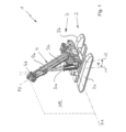
図1は、本発明による車両クレーン1を示す。たとえば、それは、互いに平行に離間した2つの履帯2a、2bを装備した下部キャリッジ2を有するチェーンドライブを備える車両クレーン1である。当然、たとえば、ここではより詳細には示されていないが、タイヤを有する下部キャリッジも使用することができる。運転室3aおよびジブ4を備える上部構造3は、下部キャリッジ2上に回転可能に配置される。通常、ジブ4は、外部基本ボックス4aおよび前記基本ボックスの内外に油圧で伸縮することができる内部ボックス4bからなる伸縮ジブとして構成される。ジブ4は、その下端を介して上部構造3に旋回可能に取り付けられ、その結果、この場合にのみ示されている水平な格納位置P1と、この場合に示され、それに対して持ち上げられた動作位置P2との間で、ジブ4を起伏させることができる。この場合に示された動作位置P2における水平に対するジブ4の傾斜は、当然、その格納位置P1におけるジブ4の向きから逸脱するすべての他の値も想定することができるので、一例として考慮されるべきである。
Figure 1 shows a
ジブ4は、垂直ラフィング平面WE内でのみ起伏することができ、その向きは、下部キャリッジ2に対して上部構造3を回転させる可能性によって、より詳細には示されていない方式で必要に応じて変更することができる。ジブ4を起伏および支持するために必要な駆動は、ラフィング平面WE上で互いに対向して位置する2つ、好ましくは正確には2つのラフィングシリンダ5a、5bを介して達成される。2つのラフィングシリンダ5a、5bは、ジブ4がこの場合に示された動作位置P2にあるとき、それらの縦軸x1、x2がそれらの間に底部で開いている広がり角aを形成するように、互いに対して配置されていることが明らかである。その上、ラフィングシリンダ5a、5bは、ジブ4の端部の外側でジブ4に作用する。
The
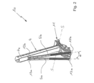
図2は、図1にすでに示されている車両クレーン1の部品のいくつかを備える本発明によるアセンブリ10を示す。具体的には、アセンブリ10は、この場合明確にするためにのみその基本ボックスに縮小されたジブ4、ならびにすべてがアセンブリ10のベースフレーム11上のそれらの下端を介して支持された2つのラフィングシリンダ5a、5bを有する。ジブ4は、水平な旋回軸Sのまわりに起伏することができるようにベースフレーム11に取り付けられ、2つのラフィングシリンダ5a、5bは、ベースフレーム11上に関節式に支持される。この目的のために、この場合、2つの示された取り付けアセンブリ12a、12bがベースフレーム11上に設けられ、2つの示された上部取り付けアセンブリ13aおよび13bがジブ4上に設けられ、これらは各々2つのラフィングシリンダ5a、5bに配置される。これらの取り付けアセンブリ12a、12b、13a、13bの各々は、より詳細には示されていない方式で、2つのラフィングシリンダ5a、5bがジブ4の起伏中に必要とされる移動の自由を可能にするために、ユニバーサルジョイントまたはボールジョイントとして設計されている。
2 shows an
その上、ラフィングシリンダ5a、5bに関連して、油圧シリンダとして設計されたラフィングシリンダ5a、5bは、好ましくはそれらのピストンロッドの上端で、その上端および下端の外側の基本ボックス4aに関節接合されることが図1から明らかである。2つのラフィングシリンダ5a、5bは、基本ボックス4aの上半分のほぼ中央で基本ボックス4aに作用する。好ましくは、2つのラフィングシリンダ5a、5bは、基本ボックス4aの縦方向に見られるように、いずれの場合も基本ボックス4aの上端および下端からも基本ボックス4aの全長の少なくとも10%、好ましくは少なくとも20%、特に好ましくは少なくとも30%離間した領域内でジブ4の基本ボックス4aに作用することが規定される。
Moreover, in relation to the luffing
基本的に、ここに示されたベースフレーム11は、下部キャリッジ2に対して回転することができる図1の車両クレーン1の上部構造3の一部であること、あるいは上部構造3自体であることが可能である。それに代わるものとして、前記ベースフレーム11が図1の車両クレーン1の下部キャリッジ2の一部であること、あるいは下部キャリッジ2自体であることが実現可能である。
Basically, the
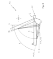
図3は、図2のアセンブリ10を次に側面図で示す。この場合、ジブ4の水平な格納位置P1が示され、これは、明確にするために、この場合はまたジブ4の基本ボックスに縮小されているが、ジブ4の動作位置P2は破線によって示されている。ジブ4は、その格納位置P1をたとえば水平方向Xと平行に延在し、一方、ラフィング平面WE上で互いに対向して位置し、横方向Yに互いに離間している2つのラフィングシリンダ5a、5bは、この図では上下に位置している。したがって、前景にあるラフィングシリンダ5bのみを見ることが可能であり、その後方に位置するラフィングシリンダ5aはそれによって隠されている。ジブ4が動作位置P2にあるときに変化するラフィングシリンダ5a、5bの傾斜は、同様に破線を使用してそれに応じて示されている。
Figure 3 shows the
図から分かるように、ラフィングシリンダ5a、5bの縦軸x1、x2は、ラフィング平面WEに投影され、水平方向Xに対して直交してラフィング平面WE内に延在する上向き方向Zは、ジブ4がその格納位置P1に配置されると、それらの間に傾斜角bを形成する。言い換えれば、ジブ4が格納位置P1にあるとき、2つのラフィングシリンダ5a、5bは、上向き方向Zに対して傾斜している。この場合、ジブ4が格納位置P1にあるとき、前記傾斜角bは約75°である。アセンブリ10の構成に応じて、ジブ4が格納位置P1にあるとき、傾斜角bはまた、ここには示されていない方式で、好ましくはまた水平方向Xの下に平行にラフィングシリンダ5a、5bが延在することができるほど大きくすることができる。
As can be seen from the figure, the longitudinal axes x1, x2 of the luffing
図4は、代替の実施形態を参照して図2および図3のアセンブリ10の構造を示す。ここに示されたアセンブリ10の図から分かるように、2つのラフィングシリンダ5a、5bの上部取り付けアセンブリ13a、13bは、当然、ジブ4の基本ボックス上に横方向に配置することもできる。この場合、2つの下部取り付けアセンブリ12a、12bは、より詳細には示されていない方式で、ラフィング平面WEに対して垂直に延在する経路Pに沿って変位することができる。前記経路は、少なくとも部分的に直線状および/または曲線状のコースを有することができ、この場合、前記経路は、例として曲線状で示されている。2つの取り付けアセンブリ12a、12bは、経路Pに沿って、互いに向かってまたは互いから離れて、それぞれ反対方向R1、R2に同時に変位できることが規定される。取り付けアセンブリ12a、12bの変位可能な設計により、2つのラフィングシリンダ5a、5bの縦軸x1、x2の間に形成される広がり角aを変更することが可能である。ジブ4が格納位置P1および/または動作位置P2にあるとき、底部でまたはベースフレーム11に向かって開いている広がり角aの変更を達成することができる。広がり角aは、0°より大きく45°までの値を想定することができ、前記角度は、好ましくはジブ4が格納位置P1にあるときよりも動作位置P2にあるときの方が大きくなることができる。たとえば、ジブ4が格納位置P1にあるとき、広がり角aは、たとえば、0°~6°とすることができ、その結果、2つのラフィングシリンダ5a、5bは、たとえば、このように装備された車両1の走行中に可能な限り最もコンパクトな寸法を得るために、互いにほぼ平行に延在する。
Figure 4 shows the structure of the
図5は、本発明によるアセンブリ10のさらなる代替の実施形態を示す。そこでは、2つのラフィングシリンダ5a、5bの間に形成された広がり角aが次に上部で開いているように、下部取り付けアセンブリ12a、12bが上部取り付けアセンブリ13a、13bの反対側に配置されていることが分かる。言い換えれば、2つのラフィングシリンダ5a、5bの配置は、この点においてベースフレーム11に向かって先細になっている。この場合、上部取り付けアセンブリ13a、13bのそれぞれの位置は、経路Pに沿って同様に変更することができ、上部で開いている広がり角aにおいて対応するばらつきをもたらす。
Figure 5 shows a further alternative embodiment of the
当然、上部および下部取り付けアセンブリ12a、12b、13a、13bは、必要に応じて頂部または底部で広がり角aを開くことができるように変位することができる。
Of course, the upper and
図6は、公道を走行することができ、それに対応して、たとえば4つの車軸に分配されたゴム車輪タイヤ2cを有する下部キャリッジ2を有する移動式クレーンとして設計された本発明による車両クレーン1の概略図を示す。典型的な方式では、垂直回転軸のまわりを旋回することができ、起伏可能なジブ4を有する上部構造3が下部キャリッジ2に取り付けられる。ジブ4が図3に関してすでに記載された実質的に水平な格納位置P1にあるとき、ジブは支持体14を介して下部キャリッジ2に支持されることが分かる。この目的のために、支持体14は、下部キャリッジ2の上面から始まり、ジブ4の基本ボックス4aの底面に向かって垂直に延在し、この位置でそれに接する。
Figure 6 shows a schematic diagram of a
1 車両クレーン
2 下部キャリッジ
2a 履帯
2b 履帯
2c 車輪タイヤ
3 上部構造
3a 運転室
4 ジブ
4a 基本ボックス
4b 内部ボックス
5a ラフィングシリンダ
5b ラフィングシリンダ
10 アセンブリ
11 ベースフレーム
12a 取り付けアセンブリ、底部
12b 取り付けアセンブリ、底部
13a 取り付けアセンブリ、頂部
13b 取り付けアセンブリ、頂部
14 支持体
a 広がり角
b 傾斜角
P 経路
P1 格納位置
P2 動作位置
R1 方向
R2 方向
S 旋回軸
W ラフィング平面
x1 縦軸
x2 縦軸
X 水平方向
Y 横方向
Z 上向き方向
Claims (11)
前記垂直ラフィング平面(WE)上で互いに対向して位置する前記ラフィングシリンダ(5a、5b)が、前記動作位置(P2)において、それらの縦軸(x1、x2)間の広がり角(a)を形成し、前記ラフィングシリンダ(5a、5b)が前記ジブ(4)の端部の外側で前記ジブ(4)に作用し、
前記ジブ(4)が前記格納位置(P1)にあるとき、前記垂直ラフィング平面(WE)上に投影されたラフィングシリンダ(5a、5b)の前記縦軸(x1、x2)、および前記垂直ラフィング平面(WE)内に延在する上向き方向(Z)が、それらの間に傾斜角(b)を形成し、
前記ジブ(4)が、ベースフレーム(11)に起伏可能に取り付けられ、前記ベースフレーム(11)が、各々がユニバーサルジョイントまたはボールジョイントとして設計され、それを介して前記ラフィングシリンダ(5a、5b)が前記ベースフレーム(11)上に関節式に支持される、下部取り付けアセンブリ(12a、12b)を有し、
前記ジブ(4)が、各々がユニバーサルジョイントまたはボールジョイントとして設計され、それを介して前記ラフィングシリンダ(5a、5b)が前記ジブ(4)に関節式に支持される、上部取り付けアセンブリ(13a、13b)を有し、
前記下部取り付けアセンブリ(12a、12b)及び/又は前記上部取り付けアセンブリ(13a、13b)のうちの少なくとも1つが、前記垂直ラフィング平面(WE)に対して垂直に延在する経路(P)に沿って可変的に位置決めすることができ、前記経路(P)が、少なくとも部分的に直線状または曲線状のコースを有し、
前記ジブ(4)が前記格納位置(P1)にあるとき、前記傾斜角(b)が80°~100°、特に好ましくは90°~97°であり、前記ジブ(4)が前記動作位置(P2)にあるとき、前記広がり角(a)が2°~30°であることを特徴とする、
車両クレーン(1)。 A vehicle crane (1) comprising a jib (4) which can be raised and lowered via at least two luffing cylinders (5a, 5b) in a vertical luffing plane (WE) between a stowed position (P1) and an operating position (P2),
the luffing cylinders (5a, 5b) lying opposite each other on the vertical luffing plane (WE) form, in the working position (P2), a spread angle (a) between their longitudinal axes (x1, x2), the luffing cylinders (5a, 5b) acting on the jib (4) outside the ends of the jib (4),
when the jib (4) is in the stowed position (P1), the longitudinal axes (x1, x2) of the luffing cylinders (5a, 5b) projected onto the vertical luffing plane (WE) and an upward direction (Z) extending in the vertical luffing plane (WE) form an inclination angle (b) between them,
the jib (4) is mounted in a hoistable manner on a base frame (11) having lower mounting assemblies (12a, 12b), each designed as a universal or ball joint, via which the luffing cylinders (5a, 5b) are articulated on the base frame (11),
the jib (4) has upper mounting assemblies (13a, 13b), each designed as a universal or ball joint, via which the luffing cylinders (5a, 5b) are articulated to the jib (4),
at least one of said lower mounting assemblies (12a, 12b) and/or said upper mounting assemblies (13a, 13b) is variably positionable along a path (P) extending perpendicular to said vertical luffing plane (WE), said path (P) having an at least partially straight or curved course,
characterised in that when the jib (4) is in the storage position (P1), the tilt angle (b) is between 80° and 100°, particularly preferably between 90° and 97°, and when the jib (4) is in the operating position (P2), the spread angle (a) is between 2° and 30°.
Vehicle crane (1).
請求項1に記載の車両クレーン(1)。 characterised in that the lower mounting assembly (12a, 12b) and/or the upper mounting assembly (13a, 13b) are simultaneously displaceable in opposite directions (R1, R2) towards or away from each other along the path (P),
A vehicle crane (1) according to claim 1 .
請求項1または2に記載の車両クレーン(1)。 characterised in that the spreading angle (a) between the longitudinal axes (x1, x2) of the two luffing cylinders (5a, 5b) can be varied when the jib (4) is in the stowed position (P1) and/or in the working position (P2),
A vehicle crane (1) according to claim 1 or 2 .
請求項1から3のいずれか一項に記載の車両クレーン(1)アセンブリ(10)。 In the storage position (P1), the spread angle (a) is 0° to 45°, preferably 0° to 6°.
A vehicle crane (1) assembly (10) according to any one of claims 1 to 3 .
請求項1に記載の車両クレーン(1)。 characterised in that the base frame (11) is part of or is the superstructure (3) of a vehicle crane (1) which can rotate relative to the undercarriage (2),
A vehicle crane (1) according to claim 1 .
請求項1に記載の車両クレーン(1)。 characterised in that the base frame (11) is a part of the undercarriage (2) of the vehicle crane (1) or is the undercarriage (2) itself,
A vehicle crane (1) according to claim 1 .
請求項1から6のいずれか一項に記載の車両クレーン(1)。 The jib (4) is a telescopic jib having a basic box (4a) and an inner box (4b) that can be telescopically moved inward and outward.
A vehicle crane (1) according to any one of the preceding claims.
請求項7に記載の車両クレーン(1)。 characterised in that the luffing cylinders (5a, 5b) act on the basic box (4a) of the jib (4),
A vehicle crane (1) according to claim 7 .
請求項1から8のいずれか一項に記載の車両クレーン(1)。 characterised in that exactly two roughing cylinders (5a, 5b) are provided,
A vehicle crane (1) according to any one of claims 1 to 8 .
請求項1から9のいずれか一項に記載の車両クレーン(1)。 The vehicle crane (1) is characterized in that it comprises a lower carriage (2),
A vehicle crane (1) according to any one of claims 1 to 9 .
請求項10に記載の車両クレーン(1)。 characterised in that when the jib (4) is in the stored position (P1), the jib (4) is supported on the lower carriage (2),
A vehicle crane (1) according to claim 10 .
Applications Claiming Priority (3)
| Application Number | Priority Date | Filing Date | Title |
|---|---|---|---|
| DE102018133493.1 | 2018-12-21 | ||
| DE102018133493.1A DE102018133493A1 (en) | 2018-12-21 | 2018-12-21 | Arrangement with a jib that can be luffed using two luffing cylinders and a suitably equipped mobile crane |
| PCT/EP2019/085718 WO2020127318A1 (en) | 2018-12-21 | 2019-12-17 | Assembly with a boom that can be luffed by two luffing cylinders, and correspondingly equipped vehicle crane |
Publications (2)
| Publication Number | Publication Date |
|---|---|
| JP2022516420A JP2022516420A (en) | 2022-02-28 |
| JP7586820B2 true JP7586820B2 (en) | 2024-11-19 |
Family
ID=69147615
Family Applications (1)
| Application Number | Title | Priority Date | Filing Date |
|---|---|---|---|
| JP2021535242A Active JP7586820B2 (en) | 2018-12-21 | 2019-12-17 | Vehicle crane having a boom that can be raised and lowered by two luffing cylinders |
Country Status (5)
| Country | Link |
|---|---|
| US (1) | US12065335B2 (en) |
| EP (1) | EP3898492A1 (en) |
| JP (1) | JP7586820B2 (en) |
| DE (1) | DE102018133493A1 (en) |
| WO (1) | WO2020127318A1 (en) |
Families Citing this family (3)
| Publication number | Priority date | Publication date | Assignee | Title |
|---|---|---|---|---|
| DE102020129454B4 (en) | 2020-11-09 | 2023-08-17 | Tadano Demag Gmbh | Mobile crane with a boom system |
| CN115043332B (en) * | 2022-06-06 | 2025-05-13 | 徐工集团工程机械股份有限公司建设机械分公司 | A crane extension module working platform and an assembly method of the extension module |
| CN115010009B (en) * | 2022-08-04 | 2022-10-25 | 山东金科星机电股份有限公司 | Special cantilever crane in pit in mine |
Citations (2)
| Publication number | Priority date | Publication date | Assignee | Title |
|---|---|---|---|---|
| WO2001014239A1 (en) | 1999-08-23 | 2001-03-01 | Bolsoe Arild | Device for handling loads and steering system for same |
| JP2003048687A (en) | 2002-04-11 | 2003-02-21 | Kato Works Co Ltd | Mounting device for triple hoisting cylinder in traveling crane |
Family Cites Families (13)
| Publication number | Priority date | Publication date | Assignee | Title |
|---|---|---|---|---|
| US2601927A (en) * | 1950-08-07 | 1952-07-01 | Wilbur G Frenzel | Hydraulic crane structure |
| GB843024A (en) | 1957-09-27 | 1960-08-04 | British Hoist And Crane Compan | Improvements in and relating to crane structures |
| US3045836A (en) | 1957-09-27 | 1962-07-24 | British Hoist And Crane Compan | Cranes and the like |
| US2996196A (en) * | 1958-12-23 | 1961-08-15 | Utility Body Company | Portable derrick having lateral movement |
| US3722706A (en) * | 1969-12-09 | 1973-03-27 | Westvaco Corp | Weight aligned grapple |
| IT959098B (en) * | 1972-06-09 | 1973-11-10 | Dolza C | IMPROVEMENT IN CIN GOLATE TRACTORS EQUIPPED WITH LIFTING MEANS ESPECIALLY FOR THE LAYING OF PIPES |
| US3792778A (en) | 1972-09-20 | 1974-02-19 | Paxton Mitchell Co | Crane boom stowing mechanism |
| US4304519A (en) * | 1979-10-29 | 1981-12-08 | Hubbard John S | Towing vehicle with side lifter |
| DE9311778U1 (en) * | 1993-08-06 | 1994-12-08 | Liebherr-Werk Ehingen Gmbh, 89584 Ehingen | Mobile crane |
| GB2316383B (en) * | 1996-08-23 | 2000-04-05 | Liebherr Werk Ehingen | Mobile crane |
| WO2005092775A1 (en) * | 2004-03-26 | 2005-10-06 | Terex-Demag Gmbh & Co. Kg | Mobile crane sytsem comprising a mobile crane and an auxiliary device for assembly of a bracing device |
| FI122539B (en) * | 2010-04-14 | 2012-03-15 | Bronto Skylift Oy Ab | Procedure for locking a boom's use position, personal lift and lift cylinder |
| SE543484C2 (en) | 2018-03-06 | 2021-03-02 | Cargotec Patenter Ab | Cargo handling vehicle for navigation in narrow aisles and method therefore |
-
2018
- 2018-12-21 DE DE102018133493.1A patent/DE102018133493A1/en active Pending
-
2019
- 2019-12-17 WO PCT/EP2019/085718 patent/WO2020127318A1/en not_active Ceased
- 2019-12-17 EP EP19832883.3A patent/EP3898492A1/en active Pending
- 2019-12-17 JP JP2021535242A patent/JP7586820B2/en active Active
- 2019-12-17 US US17/416,077 patent/US12065335B2/en active Active
Patent Citations (2)
| Publication number | Priority date | Publication date | Assignee | Title |
|---|---|---|---|---|
| WO2001014239A1 (en) | 1999-08-23 | 2001-03-01 | Bolsoe Arild | Device for handling loads and steering system for same |
| JP2003048687A (en) | 2002-04-11 | 2003-02-21 | Kato Works Co Ltd | Mounting device for triple hoisting cylinder in traveling crane |
Also Published As
| Publication number | Publication date |
|---|---|
| US20220073321A1 (en) | 2022-03-10 |
| US12065335B2 (en) | 2024-08-20 |
| DE102018133493A1 (en) | 2020-06-25 |
| WO2020127318A1 (en) | 2020-06-25 |
| EP3898492A1 (en) | 2021-10-27 |
| JP2022516420A (en) | 2022-02-28 |
Similar Documents
| Publication | Publication Date | Title |
|---|---|---|
| RU2464221C2 (en) | Self-propelled lift crane and method of its operation | |
| JP4454861B2 (en) | Cranes, especially mobile cranes | |
| JP7586820B2 (en) | Vehicle crane having a boom that can be raised and lowered by two luffing cylinders | |
| US5005714A (en) | Crane, in particular a large mobile crane | |
| JP2000198674A (en) | Crane | |
| JPH1087278A (en) | Mobile crane | |
| JP7309760B2 (en) | Vehicle crane with movable adapter between main boom and main boom overhang | |
| JP5869242B2 (en) | Aerial work platform | |
| JP2000502650A (en) | Crane truck | |
| JP7543126B2 (en) | Vehicle Crane | |
| KR20000011418A (en) | Transportable crane | |
| JP6220187B2 (en) | Crawler crane | |
| JP4683938B2 (en) | Mobile crane telescopic boom vertical deflection suppression device | |
| CN110049940B (en) | hydraulic crane | |
| CN222810787U (en) | Rock drilling rig with translation cab | |
| JP2003192273A (en) | Truck-mounted crane | |
| JPH07115827B2 (en) | Vehicle mounted hydraulic crane | |
| JP2006206232A5 (en) | ||
| JPH0724388Y2 (en) | Aerial work vehicle | |
| JP3958607B2 (en) | Work equipment | |
| JP4098875B2 (en) | Self-propelled crane | |
| JP4665230B2 (en) | Work vehicle | |
| JPH10316370A (en) | Crawler crane | |
| JP2797136B2 (en) | Base support for jib boom in self-propelled crane | |
| JPH09227073A (en) | Mobile crane |
Legal Events
| Date | Code | Title | Description |
|---|---|---|---|
| A529 | Written submission of copy of amendment under article 34 pct |
Free format text: JAPANESE INTERMEDIATE CODE: A529 Effective date: 20210816 |
|
| A621 | Written request for application examination |
Free format text: JAPANESE INTERMEDIATE CODE: A621 Effective date: 20221207 |
|
| A977 | Report on retrieval |
Free format text: JAPANESE INTERMEDIATE CODE: A971007 Effective date: 20231220 |
|
| A131 | Notification of reasons for refusal |
Free format text: JAPANESE INTERMEDIATE CODE: A131 Effective date: 20240109 |
|
| A521 | Request for written amendment filed |
Free format text: JAPANESE INTERMEDIATE CODE: A523 Effective date: 20240405 |
|
| A02 | Decision of refusal |
Free format text: JAPANESE INTERMEDIATE CODE: A02 Effective date: 20240604 |
|
| A521 | Request for written amendment filed |
Free format text: JAPANESE INTERMEDIATE CODE: A523 Effective date: 20240805 |
|
| A521 | Request for written amendment filed |
Free format text: JAPANESE INTERMEDIATE CODE: A523 Effective date: 20240821 |
|
| A521 | Request for written amendment filed |
Free format text: JAPANESE INTERMEDIATE CODE: A523 Effective date: 20240826 |
|
| A911 | Transfer to examiner for re-examination before appeal (zenchi) |
Free format text: JAPANESE INTERMEDIATE CODE: A911 Effective date: 20240913 |
|
| A131 | Notification of reasons for refusal |
Free format text: JAPANESE INTERMEDIATE CODE: A131 Effective date: 20241001 |
|
| A521 | Request for written amendment filed |
Free format text: JAPANESE INTERMEDIATE CODE: A523 Effective date: 20241007 |
|
| TRDD | Decision of grant or rejection written | ||
| A01 | Written decision to grant a patent or to grant a registration (utility model) |
Free format text: JAPANESE INTERMEDIATE CODE: A01 Effective date: 20241015 |
|
| A61 | First payment of annual fees (during grant procedure) |
Free format text: JAPANESE INTERMEDIATE CODE: A61 Effective date: 20241107 |
|
| R150 | Certificate of patent or registration of utility model |
Ref document number: 7586820 Country of ref document: JP Free format text: JAPANESE INTERMEDIATE CODE: R150 |