JP7585508B2 - Terminal position assurance member, electrical connector including same, and electrical connector assembly including same - Google Patents
Terminal position assurance member, electrical connector including same, and electrical connector assembly including same Download PDFInfo
- Publication number
- JP7585508B2 JP7585508B2 JP2023547772A JP2023547772A JP7585508B2 JP 7585508 B2 JP7585508 B2 JP 7585508B2 JP 2023547772 A JP2023547772 A JP 2023547772A JP 2023547772 A JP2023547772 A JP 2023547772A JP 7585508 B2 JP7585508 B2 JP 7585508B2
- Authority
- JP
- Japan
- Prior art keywords
- housing
- electrical connector
- tpa member
- terminal
- terminal receiving
- Prior art date
- Legal status (The legal status is an assumption and is not a legal conclusion. Google has not performed a legal analysis and makes no representation as to the accuracy of the status listed.)
- Active
Links
Images


Classifications
-
- H—ELECTRICITY
- H01—ELECTRIC ELEMENTS
- H01R—ELECTRICALLY-CONDUCTIVE CONNECTIONS; STRUCTURAL ASSOCIATIONS OF A PLURALITY OF MUTUALLY-INSULATED ELECTRICAL CONNECTING ELEMENTS; COUPLING DEVICES; CURRENT COLLECTORS
- H01R13/00—Details of coupling devices of the kinds covered by groups H01R12/70 or H01R24/00 - H01R33/00
- H01R13/40—Securing contact members in or to a base or case; Insulating of contact members
- H01R13/42—Securing in a demountable manner
- H01R13/436—Securing a plurality of contact members by one locking piece or operation
- H01R13/4367—Insertion of locking piece from the rear
- H01R13/4368—Insertion of locking piece from the rear comprising a temporary and a final locking position
-
- H—ELECTRICITY
- H01—ELECTRIC ELEMENTS
- H01R—ELECTRICALLY-CONDUCTIVE CONNECTIONS; STRUCTURAL ASSOCIATIONS OF A PLURALITY OF MUTUALLY-INSULATED ELECTRICAL CONNECTING ELEMENTS; COUPLING DEVICES; CURRENT COLLECTORS
- H01R13/00—Details of coupling devices of the kinds covered by groups H01R12/70 or H01R24/00 - H01R33/00
- H01R13/64—Means for preventing incorrect coupling
- H01R13/641—Means for preventing incorrect coupling by indicating incorrect coupling; by indicating correct or full engagement
-
- H—ELECTRICITY
- H01—ELECTRIC ELEMENTS
- H01R—ELECTRICALLY-CONDUCTIVE CONNECTIONS; STRUCTURAL ASSOCIATIONS OF A PLURALITY OF MUTUALLY-INSULATED ELECTRICAL CONNECTING ELEMENTS; COUPLING DEVICES; CURRENT COLLECTORS
- H01R13/00—Details of coupling devices of the kinds covered by groups H01R12/70 or H01R24/00 - H01R33/00
- H01R13/62—Means for facilitating engagement or disengagement of coupling parts or for holding them in engagement
- H01R13/629—Additional means for facilitating engagement or disengagement of coupling parts, e.g. aligning or guiding means, levers, gas pressure electrical locking indicators, manufacturing tolerances
-
- H—ELECTRICITY
- H01—ELECTRIC ELEMENTS
- H01R—ELECTRICALLY-CONDUCTIVE CONNECTIONS; STRUCTURAL ASSOCIATIONS OF A PLURALITY OF MUTUALLY-INSULATED ELECTRICAL CONNECTING ELEMENTS; COUPLING DEVICES; CURRENT COLLECTORS
- H01R13/00—Details of coupling devices of the kinds covered by groups H01R12/70 or H01R24/00 - H01R33/00
- H01R13/62—Means for facilitating engagement or disengagement of coupling parts or for holding them in engagement
- H01R13/639—Additional means for holding or locking coupling parts together, after engagement, e.g. separate keylock, retainer strap
-
- H—ELECTRICITY
- H01—ELECTRIC ELEMENTS
- H01R—ELECTRICALLY-CONDUCTIVE CONNECTIONS; STRUCTURAL ASSOCIATIONS OF A PLURALITY OF MUTUALLY-INSULATED ELECTRICAL CONNECTING ELEMENTS; COUPLING DEVICES; CURRENT COLLECTORS
- H01R13/00—Details of coupling devices of the kinds covered by groups H01R12/70 or H01R24/00 - H01R33/00
- H01R13/02—Contact members
- H01R13/10—Sockets for co-operation with pins or blades
- H01R13/11—Resilient sockets
-
- H—ELECTRICITY
- H01—ELECTRIC ELEMENTS
- H01R—ELECTRICALLY-CONDUCTIVE CONNECTIONS; STRUCTURAL ASSOCIATIONS OF A PLURALITY OF MUTUALLY-INSULATED ELECTRICAL CONNECTING ELEMENTS; COUPLING DEVICES; CURRENT COLLECTORS
- H01R4/00—Electrically-conductive connections between two or more conductive members in direct contact, i.e. touching one another; Means for effecting or maintaining such contact; Electrically-conductive connections having two or more spaced connecting locations for conductors and using contact members penetrating insulation
- H01R4/10—Electrically-conductive connections between two or more conductive members in direct contact, i.e. touching one another; Means for effecting or maintaining such contact; Electrically-conductive connections having two or more spaced connecting locations for conductors and using contact members penetrating insulation effected solely by twisting, wrapping, bending, crimping, or other permanent deformation
- H01R4/18—Electrically-conductive connections between two or more conductive members in direct contact, i.e. touching one another; Means for effecting or maintaining such contact; Electrically-conductive connections having two or more spaced connecting locations for conductors and using contact members penetrating insulation effected solely by twisting, wrapping, bending, crimping, or other permanent deformation by crimping
- H01R4/183—Electrically-conductive connections between two or more conductive members in direct contact, i.e. touching one another; Means for effecting or maintaining such contact; Electrically-conductive connections having two or more spaced connecting locations for conductors and using contact members penetrating insulation effected solely by twisting, wrapping, bending, crimping, or other permanent deformation by crimping for cylindrical elongated bodies, e.g. cables having circular cross-section
- H01R4/184—Electrically-conductive connections between two or more conductive members in direct contact, i.e. touching one another; Means for effecting or maintaining such contact; Electrically-conductive connections having two or more spaced connecting locations for conductors and using contact members penetrating insulation effected solely by twisting, wrapping, bending, crimping, or other permanent deformation by crimping for cylindrical elongated bodies, e.g. cables having circular cross-section comprising a U-shaped wire-receiving portion
- H01R4/185—Electrically-conductive connections between two or more conductive members in direct contact, i.e. touching one another; Means for effecting or maintaining such contact; Electrically-conductive connections having two or more spaced connecting locations for conductors and using contact members penetrating insulation effected solely by twisting, wrapping, bending, crimping, or other permanent deformation by crimping for cylindrical elongated bodies, e.g. cables having circular cross-section comprising a U-shaped wire-receiving portion combined with a U-shaped insulation-receiving portion
Landscapes
- Connector Housings Or Holding Contact Members (AREA)
Description
(関連出願)
本出願は、2021年2月9日に出願された、韓国特許出願第10-2021-0018480号に対する優先権を主張し、参照によってその全体が本明細書に組み込まれる。
(Related Applications)
This application claims priority to Korean Patent Application No. 10-2021-0018480, filed on February 9, 2021, the entire contents of which are incorporated herein by reference.
(発明の分野)
本開示は、電線対電線電気コネクタまたは電線対基板電気コネクタに関し、より詳細には、端子が電気コネクタのハウジングに完全に挿入されることを可能にし、好ましい挿入位置を維持し、端子の分離を防止する端子位置保証(TPA)部材を備える電気コネクタに関する。
FIELD OF THEINVENTION
The present disclosure relates to wire-to-wire or wire-to-board electrical connectors, and more particularly to electrical connectors having terminal position assurance (TPA) members that allow terminals to be fully inserted into a housing of the electrical connector, maintain a preferred insertion position, and prevent separation of the terminals.
一般に、電気コネクタは、雌コネクタと雄コネクタとを電気的に接続するハウジングと、ハウジングの一方の側に形成された複数の開口部にそれぞれ挿入される複数の導電端子とを備える場合がある。端子の不完全挿入または不完全結合を防止するために、端子の不完全挿入または不完全結合を検出し、好ましい端子結合状態を維持および固定するために、TPA部材(または端子位置保証部材、端子保持部、補助係止部)が使用されることが知られている。 In general, an electrical connector may include a housing that electrically connects a female connector and a male connector, and a number of conductive terminals that are inserted into a number of openings formed on one side of the housing. In order to prevent incomplete insertion or incomplete coupling of the terminals, it is known that a TPA member (or a terminal position assurance member, a terminal holding portion, an auxiliary locking portion) is used to detect incomplete insertion or incomplete coupling of the terminals and to maintain and fix a preferred terminal coupling state.
TPA部材は、TPA部材の不完全な結合状態を識別することによって1つ以上の端子が完全に装着されていないことを検出し、不完全に挿入された端子を適切な位置に配置するために、不完全に挿入された端子を好ましい挿入位置に単独で移動させるために使用される場合がある。 The TPA member may be used to detect when one or more terminals are not fully seated by identifying an incomplete mating condition of the TPA member and independently move the incompletely inserted terminal to a preferred insertion position in order to place the incompletely inserted terminal in a proper position.
TPA部材の使用は、端子の好ましい位置を保証し、端子間の結合を保証するために必要とされる場合があるが、TPA部材の使用により、部品点数が増加し、組立工程が増加するため、コストが上昇し、作業効率が低下するという問題が生じることがある。 The use of TPA materials may be required to ensure the desired positioning of the terminals and ensure proper bonding between the terminals, but the use of TPA materials can result in an increase in the number of parts and assembly steps, which can lead to problems of increased costs and reduced work efficiency.
韓国公開特許公報第10-2009-0022370号(2009年3月4日公開)は、1つのTPA部材が2つのコネクタハウジングの両方に結合される電気コネクタを開示している。このようなTPA部材は、コネクタハウジングと別途の部材として製造された後、追加的な工程を経てコネクタハウジングに組み立てられるので、追加的な組立工程によって時間および費用の面で作業効率が低下するという問題が依然として存在する。 Korean Patent Publication No. 10-2009-0022370 (published March 4, 2009) discloses an electrical connector in which one TPA member is coupled to both of two connector housings. Since such a TPA member is manufactured as a separate member from the connector housing and then assembled to the connector housing through an additional process, there still remains a problem that the additional assembly process reduces work efficiency in terms of time and cost.
本開示は、コネクタハウジングとTPA部材との単純かつ効果的な組み合わせによって上述の問題の解決策を提供する。 The present disclosure provides a solution to the above-mentioned problems through a simple and effective combination of a connector housing and a TPA member.
本開示の目的は、部品点数が少なく、簡単な製造および組立工程によって製造されるTPA部材を備える電気コネクタを提供することである。 The object of the present disclosure is to provide an electrical connector having a TPA member that has a small number of parts and is manufactured through a simple manufacturing and assembly process.
本開示の一実施形態によれば、電気コネクタは、端子受容開口を有するハウジングと、端子受容開口の外側に装着されて端子の位置を固定するTPA部材とを備える。TPA部材は、TPA部材の両端からそれぞれ延在し、ハウジングの側壁の外側に位置する第1側部カンチレバーアームと第2側部カンチレバーアームとを備える。ハウジングは、予備装着位置においてTPA部材と接触しない。ハウジングは、最終装着位置において第1側部カンチレバーアームおよび第2側部カンチレバーアームとラッチ結合される。 According to one embodiment of the present disclosure, an electrical connector includes a housing having a terminal receiving opening and a TPA member mounted outside the terminal receiving opening to fix the position of the terminal. The TPA member includes a first side cantilever arm and a second side cantilever arm extending from opposite ends of the TPA member and positioned outside the side wall of the housing. The housing does not contact the TPA member in the pre-mounted position. The housing is latched with the first side cantilever arm and the second side cantilever arm in the final mounted position.
一実施形態では、ハウジングは、予備装着位置にあるTPA部材が、ハウジングに向かう装着方向の反対方向に分離されることを防止する係止突起をさらに備えてもよい。 In one embodiment, the housing may further include a locking protrusion that prevents the TPA member in the pre-loaded position from being separated in a direction opposite to the loading direction toward the housing.
一実施形態では、TPA部材は、TPA部材の下部から延在し、ハウジングの底部の外側に位置する少なくとも1つの底部カンチレバーアームを備えてもよい。少なくとも1つの底部カンチレバーアームは、最終装着位置においてハウジングとラッチ結合されてもよい。ハウジングは、TPA部材がハウジングから分離することを防止するために、ハウジングの側壁に形成された少なくとも1つの回転防止突起をさらに備えてもよい。 In one embodiment, the TPA member may include at least one bottom cantilever arm extending from a lower portion of the TPA member and positioned outside the bottom of the housing. The at least one bottom cantilever arm may be latched with the housing in a final installed position. The housing may further include at least one anti-rotation protrusion formed on a side wall of the housing to prevent the TPA member from separating from the housing.
一実施形態では、ハウジングおよびTPA部材は、1つの射出成形金型で1回の射出成形によって形成されてもよく、そのまま予備装着位置に配置されてもよい。 In one embodiment, the housing and TPA member may be formed in a single injection molding run in a single injection mold and placed in a pre-fitted position as is.
一実施形態では、ハウジングは、TPA部材が予備装着位置から最終装着位置に移動するときにTPA部材の移動を案内するガイドリブをさらに備えてもよい。 In one embodiment, the housing may further include guide ribs to guide the movement of the TPA member as it moves from the pre-loaded position to the final loaded position.
一実施形態では、TPA部材は、予備装着位置においてハウジングの複数の端子受容開口の外側に配置される複数の歯部をさらに備えてもよい。 In one embodiment, the TPA member may further include a plurality of teeth disposed outside the plurality of terminal receiving openings of the housing in the pre-loaded position.
一実施形態では、ハウジングの複数の端子受容開口の各々は、端子が端子受容開口に装着された後に、端子の受容方向に対して垂直な方向に端子が分離または揺動することを防止するように、その中に配置されたフィンガ部分を備えてもよい。 In one embodiment, each of the plurality of terminal receiving openings in the housing may include finger portions disposed therein to prevent the terminals from separating or rocking in a direction perpendicular to the receiving direction of the terminals after the terminals are installed in the terminal receiving openings.
一実施形態では、最終装着位置において、複数の歯部の各々は、対応する端子受容開口のフィンガ部分と連携して、端子が分離または端子の受容方向において前後に揺動することを防止してもよい。 In one embodiment, in the final installation position, each of the plurality of teeth may cooperate with a finger portion of a corresponding terminal receiving opening to prevent the terminal from separating or rocking back and forth in the terminal receiving direction.
一実施形態では、ハウジングは、他の別個の電気コネクタと結合されるように複数の端子受容開口に面する側に配置された接続部をさらに備えてもよい。電気コネクタは、接続部と同一形状の接続部を有する他の電気コネクタと回転対称状態で結合されてもよい。 In one embodiment, the housing may further include a connection portion disposed on a side facing the plurality of terminal receiving openings so as to be coupled with another separate electrical connector. The electrical connector may be coupled in a rotationally symmetrical manner with another electrical connector having a connection portion of the same shape as the connection portion.
一実施形態では、複数の端子受容開口は、上下2列に配置された第1群の端子受容開口と第2群の端子受容開口とを有してもよい。 In one embodiment, the multiple terminal receiving openings may include a first group of terminal receiving openings and a second group of terminal receiving openings arranged in two rows, one above the other.
一実施形態では、ハウジングは、一方の側に雌ラッチ部を有してもよく、一方の側に対向する他方の側に雄ラッチ部を有してもよい。雄ラッチ部は、カスケード状の屈曲部を有してもよい。 In one embodiment, the housing may have a female latch portion on one side and a male latch portion on the other opposite side. The male latch portion may have a cascading bend.
本開示の一実施形態によれば、TPA部材は、電気コネクタのハウジングの外側に装着されて複数の端子の位置を固定する。TPA部材は、TPA部材の両端からそれぞれ延在し、ハウジングの側壁の外側に位置する第1側部カンチレバーアームと第2側部カンチレバーアームとを備える。TPA部材は、予備装着位置においてハウジングと接触しない。第1側部カンチレバーアームと第2側部カンチレバーアームは、最終装着位置においてハウジングにラッチ結合されてもよい。 According to one embodiment of the present disclosure, a TPA member is mounted on the outside of a housing of an electrical connector to fix the position of a plurality of terminals. The TPA member includes a first side cantilever arm and a second side cantilever arm extending from opposite ends of the TPA member and positioned outside a side wall of the housing. The TPA member does not contact the housing in a pre-mounted position. The first side cantilever arm and the second side cantilever arm may be latch-coupled to the housing in a final mounted position.
一実施形態では、TPA部材は、TPA部材の下部から延在してハウジングの底部の外側に位置し、最終装着位置においてハウジングとラッチ結合される少なくとも1つの底部カンチレバーアームと、予備装着位置においてハウジングの複数の端子受容開口の外側に配置される複数の歯部と、をさらに備えてもよい。最終装着位置にある複数の歯部の各々は、対応する端子受容開口内に挿入されて、端子の分離または受容方向における前後の揺動を防止してもよい。 In one embodiment, the TPA member may further include at least one bottom cantilever arm extending from a lower portion of the TPA member and positioned outside the bottom of the housing and latched with the housing in the final installation position, and a plurality of teeth disposed outside the plurality of terminal receiving openings of the housing in the pre-installation position. Each of the plurality of teeth in the final installation position may be inserted into a corresponding terminal receiving opening to prevent the terminals from separating or rocking back and forth in the receiving direction.
本開示の一実施形態に係る電気コネクタアセンブリは、電気コネクタと、電気コネクタに固定された導電端子と、を備える。 An electrical connector assembly according to one embodiment of the present disclosure includes an electrical connector and a conductive terminal fixed to the electrical connector.
一実施形態では、電気コネクタは、電気コネクタと同一形状の他の電気コネクタと回転対称状態で結合されてもよい。 In one embodiment, the electrical connector may be coupled in a rotationally symmetric manner to another electrical connector of the same shape as the electrical connector.
本開示の一実施形態によれば、ハウジングおよびTPAは、予備装着位置で単一工程を通じて同時に射出成形されてもよく、TPAを最終装着位置に容易に装着することができるので、製造工程が単純化され、時間および費用が節減される。 According to one embodiment of the present disclosure, the housing and TPA may be injection molded simultaneously in a single step at a pre-mounted position, and the TPA can be easily mounted at a final mounting position, thus simplifying the manufacturing process and saving time and cost.
本開示の一実施形態によれば、ハウジングおよびTPAが予備装着位置にあるとき、ハウジングおよびTAPが予備装着位置から分離することが防止されるので、組み立てが容易であり、TPAがハウジングから分離して紛失することが防止される。 According to one embodiment of the present disclosure, when the housing and TPA are in the pre-loaded position, the housing and TAP are prevented from separating from the pre-loaded position, facilitating assembly and preventing the TPA from becoming lost due to separation from the housing.
本開示の他の目的、特徴および利点は、添付の図面と関連して後述する本開示を実施するための形態に基づいて明確に理解されるであろう。図面において、同じ参照符号は同じ構成要素を示す。図面の説明は以下の通りである。 Other objects, features and advantages of the present disclosure will be clearly understood based on the detailed description of the present disclosure described below in conjunction with the accompanying drawings. In the drawings, the same reference numerals indicate the same components. The description of the drawings is as follows:
本開示の実施形態は、本開示の技術的思想を説明するために例示されたものである。本開示の権利範囲は、以下で提案される実施形態またはこれらの実施形態の詳細な説明に限定されない。 The embodiments of the present disclosure are illustrated to explain the technical ideas of the present disclosure. The scope of the present disclosure is not limited to the embodiments proposed below or the detailed description of these embodiments.
本開示で使用される全ての技術用語および科学用語は、別途に定義しない限り、本開示が属する技術分野で通常の知識を有する者が通常理解する意味を有する。本開示で使用される全ての用語は、本開示をより明確に説明するために選択されたものであり、本開示の権利範囲を限定するために選択されたものではない。 All technical and scientific terms used in this disclosure, unless otherwise defined, have the meanings commonly understood by a person of ordinary skill in the art to which this disclosure belongs. All terms used in this disclosure have been selected to more clearly describe this disclosure and not to limit the scope of the rights of this disclosure.
本開示で使用される用語「備える(comprises )」、「備える(includes)」、「有する(has )」は、当該表現を含む文言または文章が別途の意味を示さない限り、他の実施形態を含む可能性がある非制限的な用語であると理解されなければならない。 The terms "comprises," "includes," and "has" used in this disclosure should be understood to be open-ended terms that may include other embodiments, unless a word or sentence containing such expressions indicates otherwise.
本開示で使用される単数形は、文脈上明白に異なる意味を示さない限り、複数形も含み、これは、特許請求の範囲に記載された単数形にも同様に適用される。 The singular forms used in this disclosure include the plural forms unless the context clearly indicates otherwise, and this also applies to the singular forms recited in the claims.
本開示で使用される「第1」、「第2」などの用語は、複数の構成要素を互いに区別するために使用されたものであって、構成要素の順序や重要度などを限定するものではない。 Terms such as "first" and "second" used in this disclosure are used to distinguish multiple components from each other, and do not limit the order or importance of the components.
図面を参照して、互いに直交するX軸、Y軸およびZ軸による空間直交座標を参照して本開示を説明する。すなわち、XYZ直交座標上における実施形態の各構成要素について説明する。各軸方向(X軸方向、Y軸方向、Z軸方向)とは、各軸が延びる両方向を意味する。「+」の符号が付された各軸方向(+X軸方向、+Y軸方向、+Z軸方向)は、各軸が延びる両方向のうちのいずれか一方の方向である正方向を示す。符号が付された各軸方向(-X軸方向、-Y軸方向、-Z軸方向)は、各軸が延びる両方向のうちの他方である負方向を意味する。これらの用語は、本開示の理解を容易にするための基準に過ぎず、基準点によって各方向が異なるように定義されてもよい。 The present disclosure will be described with reference to the drawings and spatial Cartesian coordinates with mutually orthogonal X-axis, Y-axis, and Z-axis. That is, each component of the embodiment will be described on the XYZ Cartesian coordinate system. Each axis direction (X-axis, Y-axis, Z-axis) means both directions in which each axis extends. Each axis direction with a "+" sign (+X-axis, +Y-axis, +Z-axis) indicates the positive direction, which is one of the two directions in which each axis extends. Each axis direction with a sign (-X-axis, -Y-axis, -Z-axis) indicates the negative direction, which is the other of the two directions in which each axis extends. These terms are merely a reference for facilitating understanding of the present disclosure, and each direction may be defined differently depending on the reference point.
以下、添付図面を参照して、本開示の実施形態について説明する。添付図面において、同一または対応する構成要素には同一の参照符号を付している。なお、以下の実施形態の説明において、同一または相当する構成要素については、重複する説明を省略する場合がある。ただし、構成要素の記載が省略されていても、その構成要素がある実施形態に含まれないことを意図するものではない。 Embodiments of the present disclosure will be described below with reference to the attached drawings. In the attached drawings, identical or corresponding components are given the same reference symbols. Note that in the following description of the embodiments, duplicate descriptions of identical or corresponding components may be omitted. However, even if a description of a component is omitted, it is not intended that the component is not included in a certain embodiment.
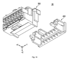
図1および図2は、本開示の第1実施形態に係る電気コネクタ10の斜視図であり、ハウジング100とTPA部材200とが互いに完全に分離されている。図3および図5は、ハウジング100およびTPA部材200が予備装着位置にある電気コネクタ10の斜視図である。電気コネクタアセンブリ1は、電気コネクタ10と、電気コネクタ10に固定された導電端子90(図8)と、端子90から延在する導線96とを備えている。電気コネクタ10は、ハウジング100と、ハウジング100に結合されたTPA部材200とを備える。ハウジング100およびTPA部材200は、単一の射出成形金型内で一度に射出成形することによって形成されてもよい。射出成形工程が実行されるとき、ハウジング100およびTPA部材200は、射出成形が完了すると同時に予備装着位置に位置決めされるように形成される。ハウジング100およびTPA部材200は、同じ材料で形成されてもよい。図1および図2は、各構成要素の説明の便宜上、ハウジング100とTPA部材200とが完全に分離された仮想状態を示している。
1 and 2 are perspective views of the
図1および図2において、電気コネクタ10は、複数の端子受容開口110を有するハウジング100と、複数の端子(図示せず)の位置を固定するために複数の端子受容開口110の外側に装着されるTPA部材200とを備える。TPA部材200は、TPA本体220と、TPA本体220の両端からそれぞれ延在し、ハウジング100の側壁(Y軸方向に垂直な側壁)の外側に位置する第1側部カンチレバーアーム250および第2側部カンチレバーアーム260とを備える。TPA部材200とハウジング100は、射出成形工程および予備装着位置において互いに接触しないように、それらの間に隙間を有するように構成される。TPA部材200は、複数の歯部210を有してもよい。
1 and 2, the
図1~図3において、TPA部材200は、TPA部材200の下部から延在し、ハウジング100の底部(-Z軸方向に垂直な側壁)の外側に位置する少なくとも1つの底部カンチレバーアーム230をさらに備えてもよい。ハウジング100は、TPA部材200との予備装着位置でTPA部材200のX軸方向への移動をガイドする少なくとも1つのガイドリブ150を備えてもよい。ガイドリブ150は、底部からZ軸方向の外側に突出し、底部に沿ってX軸方向に延在し、Y軸方向に互いに離隔する複数のガイドリブ150を備えてもよい。TPA部材200の底部カンチレバーアーム230は、ガイドリブ150に沿って摺動可能であるように構成されてもよい。一対のガイドリブ150に対応する一対の底部カンチレバーアーム230が備えられ、TPA部材200がZ軸を中心に一定以上回転することを防止する。
1 to 3, the
図3および図4において、予備装着位置では、TPA部材200のTPA本体220、第1側部カンチレバーアーム250と第2側部カンチレバーアーム260、および底部カンチレバーアーム230は、ハウジング100から隙間を有してハウジング100の外側に配置される。この構成により、ハウジング100およびTPA部材200は、単一の射出成形金型内で一度に射出成形することによって形成されてもよい。
3 and 4, in the pre-mounted position, the
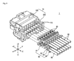
図5および図6において、複数の歯部210は、TPA部材200の予備装着位置において、ハウジング100の複数の端子受容開口110の外側にそれぞれ配置される。複数の歯部210は、ハウジング100に対するTPA部材200の予備装着位置(図5)から最終装着位置(図11)への相対移動に従って、ハウジング100の複数の端子受容開口110にそれぞれ挿入されるように構成される。端子受容開口110は、それぞれ端子着座部111を有してもよい。端子90がハウジング100の端子受容開口110の通路に挿入されると、端子90は端子着座部111上に位置決めされる。端子90が端子着座部111上に位置決めされると、TPA部材200は、予備装着位置から最終装着位置までハウジング100に向かって相対的に移動し、ハウジング100に固定され、その結果、TPA部材200は、端子90を端子着座部111上に着座した状態に維持するように機能する。
5 and 6, the
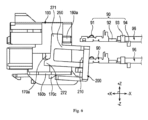
図6および図7は、本開示の第1実施形態に係る電気コネクタ10を端子90とともに示す側面図であり、ハウジング100およびTPA部材200が予備装着位置にある状態を示している。図1および図5に示すように、ハウジング100は、端子受容開口110によって形成される通路の2列の配列110a、110bを有してもよい。端子受容開口の配列は、1列または2列以上の配列で形成されてもよい。
6 and 7 are side views of the
端子90は、他の別個の電気コネクタの端子と接触するように構成された接触部91と、接触部91から長手方向に延在する延在部92と、端子90を導線96に固定する導線固定部93と、を備えてもよい。各端子90には、導電線部を有する導線96が接続されている。端子90は、後述するハウジング100のフィンガ部113(図9)に結合される端子ホルダ94を備えてもよい。端子ホルダ94は、金属材料を折り曲げることによって形成されてもよい。
The
図6および図8において、TPA部材200が予備装着位置にあるとき、端子配列90はハウジング100内に挿入される。ハウジング100は、TPA部材200が予備装着位置にあるとき、または端子配列90がハウジング100に挿入されている間に、TPA部材200がハウジング100から分離されるのを防止するための係止突起160aを備える。具体的に、ハウジング100の係止突起160aは、TPA部材200がハウジング100に装着される方向と反対方向に分離するか、または図面を見た方向からY軸を中心に時計方向に一定以上回転することを防止することによって、TPA部材200がハウジング100から分離することを防止する。係止突起160aは、ハウジング100の左右側壁(Y軸方向に垂直な両側壁)にそれぞれ形成されてもよい。
6 and 8, when the
図6において、TPA部材200が予備装着位置(図6)から最終装着位置(図11)までハウジング100に向かって相対的に移動すると、TPA部材200の第1側部カンチレバーアーム250と第2側部カンチレバーアーム260および底部カンチレバーアーム230は、それぞれ対応する位置でハウジングの側壁(Y軸方向の側壁、-Z軸方向の側壁)にラッチ結合される。ハウジングの側壁にはラッチ結合のためのラッチ手段が備えられ、カンチレバーアームには凹部、穴、またはスリーブが備えられてもよい。別の実施形態では、ラッチ結合のためのラッチ手段は、ハウジングに形成された凹部、穴、またはスリーブを有してもよく、フック形状のラッチがカンチレバーアームに設けられてもよい。ラッチ結合は、様々な他の方法の可撓性および非可撓性結合を備えてもよい。
6, when the
図1~図4を参照すると、本開示の第1実施形態において、ラッチ170a、170b、170c、170dは、ハウジングの側壁に設けられてもよく、カンチレバーアーム250、260、230は、ラッチと結合するための穴を備えてもよい。ラッチ170a、170b、170c、170dは、予備装着位置で係止突起160aと同様に、図面を見た方向からTPA部材200がY軸を中心に時計回り方向に一定以上回転することを防止して、TPA部材200がハウジング100から分離することを防止する係止突起の役割を果たすように構成されてもよい。これを達成するために、TPA部材200の第1側部カンチレバーアーム250と第2側部カンチレバーアーム260は、回転中にラッチ170a、170bよりも良好に制限されるように、その端部を突出させるノーズ271、272部分を備えてもよい。TPA部材200の底部カンチレバーアーム230は、ラッチ結合によって対応する位置でハウジング100の底部(-Z軸方向に垂直な面)に固定されてもよい。本実施形態では、底部カンチレバーアーム230上に形成された穴が、ハウジング100上に形成されたラッチ170c、170dに固定される。
1 to 4, in the first embodiment of the present disclosure, the
図1および図2を参照すると、ラッチ170a、170b、170c、170dは、+X軸方向を向く固定面171a、171b、171c、171dを備えてもよく、TPA部材200は、固定面に対応して-X軸方向を向く固定対応面251a、251b、251c、251dを備えてもよい。ハウジング100およびTPA部材200が予備装着位置にあるとき、固定対応面251a、251b、251c、251dは、固定面171a、171b、171c、171dに対して-X軸方向に位置してもよく、ハウジング100およびTPA部材200が最終装着位置にあるとき、TPA部材220の固定対応面251a、251b、251c、251dは、ラッチの固定面171a、171b、171c、171dに接触して係止される。
With reference to Figures 1 and 2, latches 170a, 170b, 170c, 170d may have fixed
第1実施形態では、固定面171a、171b、171c、171dは、ラッチ170a、170b、170d、170dに形成されているが、固定面は、ハウジングの凹部や段部などの種々の構造によって形成されていてもよい。また、第1実施形態では、TPA部材200の固定対応面251a、251b、251c、251dは、カンチレバーアーム250、260、230の穴の+X軸方向の境界を形成する部分であったが、後述する第2実施形態(図16~図19)では、TPA部材の固定対応面は、カンチレバーアームのフックなどの種々の構造によって形成されてもよい。
In the first embodiment, the fixing
TPA部材200が予備装着位置から最終装着位置に移動する際に、TPA部材200の固定対応面251a、251b、251c、251dを固定面171a、171b、171c、171dに案内するために、第1実施形態(図1および図2)のように、ラッチ170a、170b、170c、170dの-X軸方向を向く面に固定ガイド傾斜面173a、173b、173c、173dが形成されてもよく、後述する第2実施形態(図18および図19)のように、カンチレバーアームの+X軸方向を向く面に固定ガイド傾斜面453a、453bが形成されてもよい。例えば、図1および図2を参照すると、固定ガイド傾斜面173a、173b、173c、173dは、TPA部材200の固定対応面251a、251b、251c、251dがラッチ170a、170b、170c、170dを+X軸方向に乗り越えるようにガイドするように、ラッチ170a、170b、170c、170dが+X軸方向に突出する方向に次第に高くなるように形成される。
In order to guide the fixed corresponding
図1~図4を参照すると、係止突起160aは、+X軸方向を向く規制面161を有し、TPA部材200は、規制面161に対応して-X軸方向を向く規制対応面255を有する。ハウジング100およびTPA部材200が予備装着位置にあるとき、規制対応面255は、規制面161に対して+X軸方向に位置する。TPA部材200が予備装着位置からハウジング100から完全に分離する方向(-X軸方向)に移動すると、規制面161が規制対応面255に当接することで、TPA部材200がハウジング100から分離することが防止される。
Referring to Figures 1 to 4, the locking
上述したようなラッチ結合のための構造を有する本実施形態では、ラッチの固定面171a、171b、171c、171dとTPA部材の固定対応面251a、251b、251c、251dとの間のX軸上の位置関係を変更するために、固定ガイド傾斜面173a、173b、173c、173dが設けられる。一方、ハウジング100の係止突起160aとこれに対応するTPA部材200の分離防止構造とを有する実施形態では、係止突起の規制面161とTPA部材の規制対応面255との位置関係がX軸上で変化することを防止するために、上述したガイド傾斜面に対応する構造は設けられていない。例えば、仮想分離状態を示す図1および図2を参照すると、係止突起の規制面161およびTPA部材の規制対応面255は、X軸に垂直な面として形成されており、係止突起160aの-X軸方向の面163および仮想分離状態において面163に対向するTPA部材の対応面257も、X軸に垂直な面として形成されている。したがって、以下に説明するように、ハウジング100およびTPA部材200は、塑性変形または損傷なしには、予備装着位置(図3)から完全分離状態(図1および図2)に移動されないように構成されてもよい。加えて、ハウジング100およびTPA部材200は、塑性変形または損傷なしに完全分離状態(図1および図2)から予備装着位置(図3)に移動されないように構成されてもよい。
In this embodiment having the structure for latch coupling as described above, fixed guide inclined
図7において、ハウジング100は、図面を見た方向からTPA部材200がY軸を中心に反時計方向に一定以上回転することを防止する回転防止突起160bを備える。回転防止突起160bは、TPA部材200の底部カンチレバーアーム230がハウジング100の底部から離れる方向に回転することを防止し、TPA部材200がハウジング100から分離されることを防止する。回転防止突起160bは、ハウジング100の左右側壁(Y軸方向に垂直な両側壁)にそれぞれ形成されてもよい。
In FIG. 7, the
図9~図11は、図6の電気コネクタ10において、端子90がハウジング100に挿入され(図10)、TPA部材200がハウジング100に固定されて(図11)、ハウジングおよびTPA部材が予備装着位置から最終装着位置に達するまでの工程を示す。図9において、ハウジング100の端子受容開口110の各々は、端子受容開口110の通路に挿入された端子90を固定するために端子ホルダ94と結合されるフィンガ部分113を備える。図9(b)に示すように、端子90がハウジング100に完全に挿入されると、フィンガ部113が端子ホルダ94に圧入されてもよい。図9(c)において、フィンガ部113が端子ホルダ94に結合された後、TPA部材200が最終装着位置に移動してハウジング100に結合されると、TPA部材200の歯部210は、ハウジング100のフィンガ部113と連携して、端子90が分離または受容方向において前後に揺動することを防止する。具体的には、一実施形態では、図10(b)および図11(b)に示すように、歯部は、ハウジング100のフィンガ部分113と接触または近接して構成されてもよい。別の実施形態では、図10(c)および図11(c)に示すように、歯部210は、ハウジング100のフィンガ部分113に直接接触せずに構成されてもよく、端子ホルダ94のみに接触または近接して構成されてもよい。
9 to 11 show the process of inserting the terminal 90 into the housing 100 (FIG. 10), fixing the
図10(b)および図11(b)において、ハウジング100は、TPA部材200が予備装着位置から最終装着位置へ移動する際に、TPA部材200の歯部210の移動を案内する傾斜面190を有している。傾斜面190は、TPA部材200が予備装着位置から最終装着位置に移動する際に、TPA部材200が傾斜面190に沿って摺動して上昇するように案内し、TPA部材200のアーム250、260、230がハウジングのラッチ170a、170b、170c、170dを乗り越えるように案内してもよい。別の実施形態では、図10(c)および図11(c)に示すように、TPA部材200は、TPA部材200が予備装着位置から最終装着位置に移動するときに、TPA部材200のハウジング100に対する移動をそれ自体で案内する傾斜部290を有してもよい。TPA部材200が予備装着位置から最終装着位置に移動するとき、TPA部材200の傾斜部290は、ハウジング100上を摺動してもよく、TPA部材200を上昇させるように案内してもよく、TPA部材200の底部カンチレバーアーム230をハウジングのラッチ170c、170dを乗り越えて固定するように案内してもよい。例えば、後述する第3実施形態に係るTPA部材600(図21)が傾斜部を有していてもよい。
10(b) and 11(b), the
図12は、本開示の第1実施形態に係る複数の端子が装着された電気コネクタ10と、同一形状の他の電気コネクタC10とが、結合前に回転対称に配置された状態を示す。図13~図15は、一対の電気コネクタアセンブリ1、Clが互いに結合された状態を示している。本実施形態では、電気コネクタ10は、同一形状の2つの電気コネクタ10が互いに結合可能に構成される。互いに結合可能な同一形状の電気コネクタ10は、「ジェンダーレスコネクタ」と呼ばれる場合がある。ジェンダーレスコネクタは、雌コネクタと雄コネクタとを個別に製造する必要がなく、1種類の製品のみを製造することができるので、製造コストおよび利便性を向上させることができ、ユーザが雌コネクタと雄コネクタとを区別せずに電気コネクタを使用することができるので、使用利便性を向上させることができる。以下、ジェンダーレスコネクタの実施形態を参照して説明するが、本開示はこれに限定されるものではない。
Figure 12 shows the state in which the
一方の電気コネクタ10と他方の電気コネクタC10とを対向して配置し、X軸を中心に180°回転させると、一対の電気コネクタ10、C10が互いに結合可能に構成されてもよい。具体的には、電気コネクタ10のハウジング100は、他の別個の電気コネクタC10と結合されるように複数の端子受容開口110に面する側に配置された接続部130を備える。図13に示すように、電気コネクタ10は、接続部130と同一形状の接続部130を有する他の電気コネクタC10と回転対称状態で結合される。
The pair of
図12において、ハウジング100は、複数の端子90に対応する複数の接続部130を有してもよい。複数の接続部130は、上下に配置された2列の配列130a、130bを有していてもよい。複数の接続部130の配列は、1列または2列以上の配列で形成されてもよい。図12および図14において、第1列の接続部130aと第2列の接続部130bとの間には、隙間137および/または層膜136が形成されていてもよい。図15において、ハウジング100は、複数の接続部130a、130bのうちの隣接する2つの接続部の間に配置された隔壁135を備えてもよい。複数の接続部130aは、それぞれ隔壁135によって区分される端子受容開口110の通路を形成してもよい。他の電気コネクタC10のハウジング100の層膜136は、一実施形態における電気コネクタ10のハウジング100の隙間137に挿入されてもよい。隔壁135、隙間137、および/または層膜136を形成することにより、隣接する端子間の絶縁効果をさらに高めることができる。
In FIG. 12, the
図12に示すように、一実施形態では、第1列の接続部130aの全てが雌接続部として形成されてもよく、第2列の接続部130bの全てが雄接続部として形成されてもよい。これらは逆に配置されてもよい。
As shown in FIG. 12, in one embodiment, all of the
図12において、ハウジング100は、一方の側に雌ラッチ部145を有し、一方の側に対向する他方の側に雄ラッチ部141を有し、雄ラッチ部は、カスケード状の屈曲部141aを有してもよい。
In FIG. 12, the
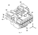
図16~図20を参照して、第2実施形態に係る電気コネクタ50について、上述した第1実施形態に係る電気コネクタ10との相違点を中心に説明する。第2実施形態において、TPA部材400とハウジング300との間の結合方法は、TPA部材400のカンチレバーアームにフックが設けられ、それに対応してハウジング300に凹部または段部が形成される構造によって達成されてもよい。図16は、各構成要素の説明の便宜上、ハウジング300とTPA部材400とが完全に分離された仮想的な状態を示している。図17および図18は、TPA部材400の底部カンチレバーアーム430がフック形状を備え、フック結合方法でハウジング300と結合される一実施形態を示す。図19および図20は、TPA部材400の第1側部カンチレバーアーム450と第2側部カンチレバーアーム460がフック形状を備え、フック結合方法でハウジング300と結合される一実施形態を示す。
With reference to Figures 16 to 20, the
以下、図21~図24を参照して、第3実施形態に係る電気コネクタ50について、上述した第1実施形態に係る電気コネクタ10との相違点を中心に説明する。図21は、本開示の第3実施形態に係る電気コネクタ50を示しており、ハウジング500とTPA部材600とが互いに完全に分離されている。図21は、各構成要素の説明の便宜上、ハウジング500とTPA部材600とが完全に分離された仮想的な状態を示している。図22および図23は、ハウジングおよびTPA部材600が予備装着位置にある状態の電気コネクタ50を示す。TPA部材600の第1側部カンチレバーアーム650と第2側部カンチレバーアーム660は、それぞれ対応する位置でハウジングの側壁(Y軸方向の側壁)にラッチ結合されてもよい。
The
電気コネクタ50のハウジング500は、第1列の配列の端子のみを受容するように構成されてもよく、第1列の配列の端子受容開口510を有してもよい。第1列の配列の接続部530は、他の別個の電気コネクタC50と結合されるように端子受容開口510に面する側に設けられる。ハウジング500は、TPA部材600が予備装着位置にあるとき、または端子配列がハウジング500内に挿入されている間に、TPA部材600がハウジング500から分離されるのを防止するため係止突起560aを備える。ハウジング500は、図面を見た方向からTPA部材600がY軸を中心に反時計方向に一定以上回転することを防止する回転防止突起560bを備える。回転防止突起560bは、ハウジング500の左右側壁(Y軸方向に垂直な両側壁)にそれぞれ形成されてもよい。
The
電気コネクタ50は、同一形状の他の別個の電気コネクタC50と結合可能に構成されたジェンダーレスコネクタであってもよい。図24を参照すると、電気コネクタ50は、同一形状の他の電気コネクタC50と回転対称状態で結合されてもよい。このため、電気コネクタ50は、隔壁135および層膜136を備えていなくてもよい。
The
別の実施形態では、電気コネクタ50のハウジング500の接続部530の各々は、側壁の高さの半分以下であるように構成されてもよい。この場合、接続部530の側壁は、別の電気コネクタの接続部530の側壁と結合されてもよく、それによって、端子受容開口510の通路を形成してもよい。
In another embodiment, each of the
本開示に係る電気コネクタ10、30、50を製造するとき、ハウジング100、300、500とTPA部材200、400、600とを同時に射出成形するために、ハウジング100、300、500とTPA部材200、400、600との間の隙間に外部射出成形部品を挿入してもよく、この場合、ハウジング100、300、500とTPA部材200、400、600とを射出成形した後、射出成形部品を除去すると、ハウジング100、300、500とTPA部材200、400、600とは、別途の組立工程を経ずに予備結合状態で別途の部材として成形されてもよい。
When manufacturing the
ハウジング100、300、500およびTPA部材200、400、600は、TPA部材200、400、600が相対位置に配置された状態で、ハウジング100、300、500とTPA部材200、400、600との間の隙間が、複数の外部射出成形部品のうちの1つ(「隔壁射出成形部品」と称する)が外部から直線方向に挿入可能な空間で形成されるように構成されてもよい。これにより、電気コネクタ10の製造工程において、ハウジング100、300、500とTPA部材200、400、600との間の空間に隔壁射出成形部品が挿入された状態でハウジング100、300、500およびTPA部材200、400、600を射出成形して硬化させた後、隔壁射出成形部品を直線方向に外側に引き出すことによって、予備装着位置にあるハウジング100、300、500およびTPA部材200、400、600を製造することができる。ハウジング100、300、500とTPA部材200、400、600との間の隙間を形成する全ての空間は、それぞれ直線方向に挿入可能な隔壁射出成形部品(図示せず)によって形成されてもよい。例えば、隙間を形成する空間のうち、空間g1(図19参照)は、外部から+Z軸方向に挿入可能な隔壁射出成形部品によって形成されてもよく、隙間を形成する空間のうち、空間g2(図19参照)は、外部から+X軸方向に挿入可能な隔壁射出成形部品によって形成されてもよい。
The
一実施形態では、TPA部材200、400、600は、TPA部材200、400、600が予備装着位置から-X軸方向に移動するとき、係止突起によって係止され、ハウジング100、300、500から分離されることを防止するように構成されてもよい。この場合、TPA部材200、400、600とハウジング100、300、500は、弾性限界範囲内の変形によって互いに完全に分離されないように構成されてもよい。また、TPA部材200、400、600とハウジング100、300、500とが予備装着位置ではない完全分離状態で別途に成形される場合、係止突起によってTPA部材200、400、600とハウジング100、300、500との結合が不可能になることがある。これらの実施形態によれば、TPA部材200、400、600をハウジング100、300、500との予備結合状態(すなわち、予備装着位置にある状態)にしてもよく、ハウジング100、300、500から完全に分離して取り外されることを防止してもよいので、ハウジング内に端子を配置する作業が容易であり、TPA部材がハウジングから分離して紛失することを防止することができる。
In one embodiment, the
本開示の技術的思想は、上述したいくつかの実施形態および添付図面に示された例を通じて説明されたが、本開示の技術的思想および範囲を逸脱しない範囲内で、本開示が属する技術分野における通常の知識を有する者が理解可能な多様な置換、変形および変更が可能であることに留意すべきである。加えて、置換、変形、および変更は、本明細書に添付された特許請求の範囲に属すると見なされるべきである。 The technical idea of the present disclosure has been described through the examples shown in the above-mentioned embodiments and the attached drawings, but it should be noted that various substitutions, modifications, and changes that can be understood by a person having ordinary knowledge in the technical field to which the present disclosure belongs are possible without departing from the technical idea and scope of the present disclosure. In addition, the substitutions, modifications, and changes should be considered to fall within the scope of the claims attached to this specification.
Claims (14)
前記TPA部材は、該TPA部材の両端からそれぞれ延在し、前記ハウジングの側壁の外側に位置する第1側部カンチレバーアームと第2側部カンチレバーアームとを備え、
前記ハウジングは、予備装着位置において前記TPA部材と接触せず、
前記ハウジングは、最終装着位置において前記第1側部カンチレバーアームおよび第2側部カンチレバーアームとラッチ結合され、
前記ハウジングは、前記予備装着位置にあるTPA部材が、前記ハウジングに向かう装着方向の反対方向に分離することを防止する係止突起をさらに備えることを特徴とする、電気コネクタ。 An electrical connector comprising: a housing having a terminal receiving opening; and a TPA member attached to the outside of the terminal receiving opening to fix the position of the terminal,
the TPA member includes a first lateral cantilever arm and a second lateral cantilever arm extending from opposite ends of the TPA member and positioned outside a side wall of the housing;
the housing does not contact the TPA member in a pre-loaded position;
the housing is latched to the first and second lateral cantilever arms in a final mounted position ;
11. The electrical connector according to claim 10, wherein said housing further comprises a locking protrusion for preventing separation of said TPA member in said pre-installed position in a direction opposite to an installation direction toward said housing .
前記ハウジングは、前記TPA部材が前記ハウジングから分離されることを防止するために、該ハウジングの側壁に形成された少なくとも1つの回転防止突起をさらに備えることを特徴とする、請求項1に記載の電気コネクタ。 the TPA member includes at least one bottom cantilever arm extending from a lower portion of the TPA member and positioned outside a bottom of the housing and latched to the housing in the final installed position;
10. The electrical connector of claim 1, wherein said housing further comprises at least one anti-rotation protrusion formed on a side wall of said housing to prevent said TPA member from being separated from said housing.
前記電気コネクタは、前記接続部と同一形状の接続部を有する他の電気コネクタと回転対称状態で結合可能であることを特徴とする、請求項1に記載の電気コネクタ。 The housing further includes a connecting portion disposed on a side facing the terminal receiving openings so as to be connected to another separate electrical connector;
2. The electrical connector according to claim 1, wherein the electrical connector is connectable in a rotationally symmetrical state with another electrical connector having a connecting portion having the same shape as the connecting portion.
該雄ラッチ部は、カスケード状の屈曲部を有することを特徴とする、請求項8に記載の電気コネクタ。 the housing has a female latch portion on one side and a male latch portion on the other side opposite the one side;
9. The electrical connector of claim 8 , wherein said male latch portion includes a cascading bend.
該TPA部材は、該TPA部材の両端からそれぞれ延在し、前記ハウジングの側壁の外側に位置する第1側部カンチレバーアームと第2側部カンチレバーアームとを備え、
前記TPA部材は、予備装着位置において、前記ハウジングと接触せず、該ハウジングが備える係止突起により、前記ハウジングに向かう装着方向の反対方向に分離することが防止され、
前記第1側部カンチレバーアームと第2側部カンチレバーアームは、最終装着位置において前記ハウジングにラッチ結合されることを特徴とする、TPA部材。 A TPA member that is attached to the outside of a housing of an electrical connector to fix the positions of a plurality of terminals,
the TPA member includes a first lateral cantilever arm and a second lateral cantilever arm extending from opposite ends of the TPA member and positioned outside a side wall of the housing;
In the pre-installation position, the TPA member does not contact the housing and is prevented from separating in a direction opposite to the installation direction toward the housing by a locking protrusion provided on the housing;
The TPA member, wherein the first and second lateral cantilever arms are latched to the housing in a final installed position.
前記TPA部材は、前記予備装着位置において前記ハウジングの複数の端子受容開口の外側に配置される複数の歯部をさらに備え、
前記最終装着位置にある複数の歯部の各々は、対応する端子受容開口に挿入されて、前記端子の分離または受容方向における前後の揺動を防止する、請求項11に記載のTPA部材。 the TPA member includes at least one bottom cantilever arm extending from a lower portion of the TPA member and positioned outside a bottom of the housing and latched to the housing in the final installed position;
the TPA member further comprising a plurality of tines disposed outside the plurality of terminal receiving openings of the housing in the pre-loaded position;
The TPA member of claim 11 , wherein each of the plurality of teeth in the final installed position is inserted into a corresponding terminal receiving opening to prevent the terminal from rocking back and forth in a separation or receiving direction.
請求項6に記載の電気コネクタと、
前記電気コネクタに挿入されて固定され、該電気コネクタに挿入された後に該電気コネクタのフィンガ部に結合される端子ホルダを有する導電端子と、を備えることを特徴とする、電気コネクタアセンブリ。 1. An electrical connector assembly comprising:
The electrical connector according to claim 6 ;
a conductive terminal having a terminal holder that is inserted into and secured to the electrical connector and that is coupled to a finger portion of the electrical connector after being inserted into the electrical connector.
Applications Claiming Priority (3)
| Application Number | Priority Date | Filing Date | Title |
|---|---|---|---|
| KR1020210018480A KR102520973B1 (en) | 2021-02-09 | 2021-02-09 | Terminal position assurance member, electrical connector comprising the same, and electrical connector assembly comprising the same |
| KR10-2021-0018480 | 2021-02-09 | ||
| PCT/IB2022/050698 WO2022172112A1 (en) | 2021-02-09 | 2022-01-27 | Terminal position assurance member, electrical connector comprising the same, and electrical connector assembly comprising the same |
Publications (2)
| Publication Number | Publication Date |
|---|---|
| JP2024506317A JP2024506317A (en) | 2024-02-13 |
| JP7585508B2 true JP7585508B2 (en) | 2024-11-18 |
Family
ID=82838181
Family Applications (1)
| Application Number | Title | Priority Date | Filing Date |
|---|---|---|---|
| JP2023547772A Active JP7585508B2 (en) | 2021-02-09 | 2022-01-27 | Terminal position assurance member, electrical connector including same, and electrical connector assembly including same |
Country Status (5)
| Country | Link |
|---|---|
| US (1) | US20240072492A1 (en) |
| JP (1) | JP7585508B2 (en) |
| KR (2) | KR102520973B1 (en) |
| CN (1) | CN116868452A (en) |
| WO (1) | WO2022172112A1 (en) |
Families Citing this family (2)
| Publication number | Priority date | Publication date | Assignee | Title |
|---|---|---|---|---|
| US12191603B2 (en) * | 2021-06-03 | 2025-01-07 | Molex, Llc | First electrical connector, second electrical connector and electrical connector assembly |
| KR20250000265A (en) | 2023-06-26 | 2025-01-03 | (주)우주일렉트로닉스 | Direct Connection Type Connector Apparatus with Auto Combined Function |
Citations (4)
| Publication number | Priority date | Publication date | Assignee | Title |
|---|---|---|---|---|
| JP2008147074A (en) | 2006-12-12 | 2008-06-26 | Japan Aviation Electronics Industry Ltd | connector |
| JP2008198554A (en) | 2007-02-15 | 2008-08-28 | Sumitomo Wiring Syst Ltd | Connector |
| US20180301842A1 (en) | 2015-10-29 | 2018-10-18 | Molex, Llc | Power connector |
| WO2020137454A1 (en) | 2018-12-27 | 2020-07-02 | 株式会社オートネットワーク技術研究所 | Connector |
Family Cites Families (12)
| Publication number | Priority date | Publication date | Assignee | Title |
|---|---|---|---|---|
| JP2574771Y2 (en) * | 1992-10-07 | 1998-06-18 | 住友電装株式会社 | connector |
| US5486118A (en) * | 1994-10-03 | 1996-01-23 | Molex Incorporated | Electrical connector with terminal position assurance device and guide means for a mating connector |
| JP3099712B2 (en) * | 1995-03-16 | 2000-10-16 | 住友電装株式会社 | Method for manufacturing connector, mold for manufacturing connector, method for manufacturing resin molded product, and mold used for this |
| KR100866084B1 (en) * | 2007-03-08 | 2008-10-30 | 한국단자공업 주식회사 | Connector for confirming terminal mating |
| KR100868950B1 (en) * | 2007-03-30 | 2008-11-17 | 한국단자공업 주식회사 | Connector housing |
| KR100896202B1 (en) | 2007-08-30 | 2009-05-11 | 한국단자공업 주식회사 | connector |
| US7867042B2 (en) * | 2008-03-26 | 2011-01-11 | Tyco Electronics Corporation | Connector assembly with a low profile terminal position assurance member |
| US20100055954A1 (en) * | 2008-08-29 | 2010-03-04 | Tyco Electronics Corporation | Sealed electrical connector |
| KR200466410Y1 (en) * | 2008-12-18 | 2013-04-18 | 한국단자공업 주식회사 | Connector |
| US7976326B2 (en) * | 2008-12-31 | 2011-07-12 | Fci Americas Technology Llc | Gender-neutral electrical connector |
| KR20100008467U (en) * | 2009-02-17 | 2010-08-26 | 한국단자공업 주식회사 | Connector |
| JP2015144083A (en) * | 2014-01-31 | 2015-08-06 | 株式会社オートネットワーク技術研究所 | Male and female common terminal fittings and connectors using the same |
-
2021
- 2021-02-09 KR KR1020210018480A patent/KR102520973B1/en active Active
-
2022
- 2022-01-27 US US18/275,222 patent/US20240072492A1/en active Pending
- 2022-01-27 JP JP2023547772A patent/JP7585508B2/en active Active
- 2022-01-27 WO PCT/IB2022/050698 patent/WO2022172112A1/en not_active Ceased
- 2022-01-27 CN CN202280014159.1A patent/CN116868452A/en active Pending
-
2023
- 2023-04-04 KR KR1020230044028A patent/KR102734766B1/en active Active
Patent Citations (4)
| Publication number | Priority date | Publication date | Assignee | Title |
|---|---|---|---|---|
| JP2008147074A (en) | 2006-12-12 | 2008-06-26 | Japan Aviation Electronics Industry Ltd | connector |
| JP2008198554A (en) | 2007-02-15 | 2008-08-28 | Sumitomo Wiring Syst Ltd | Connector |
| US20180301842A1 (en) | 2015-10-29 | 2018-10-18 | Molex, Llc | Power connector |
| WO2020137454A1 (en) | 2018-12-27 | 2020-07-02 | 株式会社オートネットワーク技術研究所 | Connector |
Also Published As
| Publication number | Publication date |
|---|---|
| US20240072492A1 (en) | 2024-02-29 |
| KR20220114893A (en) | 2022-08-17 |
| WO2022172112A1 (en) | 2022-08-18 |
| KR102520973B1 (en) | 2023-04-13 |
| JP2024506317A (en) | 2024-02-13 |
| KR102734766B1 (en) | 2024-11-28 |
| KR20230052856A (en) | 2023-04-20 |
| CN116868452A (en) | 2023-10-10 |
Similar Documents
| Publication | Publication Date | Title |
|---|---|---|
| JP3995174B2 (en) | Electrical connector | |
| KR100933261B1 (en) | Connector, connector assembly and its connection method | |
| JP2622938B2 (en) | Electrical connector with terminal position assurance member | |
| JP3066588B2 (en) | Connector device having terminal holding device | |
| JP7585508B2 (en) | Terminal position assurance member, electrical connector including same, and electrical connector assembly including same | |
| US6099330A (en) | Connector with lever | |
| JPH11312547A (en) | Mating connector | |
| JP3960430B2 (en) | Electrical connector | |
| JP2001052798A (en) | Connector connection structure | |
| US7500875B2 (en) | Contact housing for an electrical plug connection | |
| JP2020017523A (en) | Connector housing and terminal position assurance joint clip site | |
| JP2020202035A (en) | Connector and wire with connector | |
| JP6501339B2 (en) | Electrical connector housing | |
| JP2799446B2 (en) | connector | |
| JP7762124B2 (en) | connector | |
| US20250239801A1 (en) | Connector and connector device | |
| CN112864685A (en) | Connector structure | |
| KR102583249B1 (en) | Connector | |
| JP2004186078A (en) | Connector | |
| US20230208065A1 (en) | Connector and connector device | |
| JP2024168302A (en) | connector | |
| WO2024242107A1 (en) | Connector | |
| CN121172488A (en) | Connector with a plurality of connectors | |
| JP2025122972A (en) | Wire-to-Wire Connectors | |
| JP2025007703A (en) | connector |
Legal Events
| Date | Code | Title | Description |
|---|---|---|---|
| A621 | Written request for application examination |
Free format text: JAPANESE INTERMEDIATE CODE: A621 Effective date: 20230808 |
|
| A977 | Report on retrieval |
Free format text: JAPANESE INTERMEDIATE CODE: A971007 Effective date: 20240606 |
|
| A131 | Notification of reasons for refusal |
Free format text: JAPANESE INTERMEDIATE CODE: A131 Effective date: 20240611 |
|
| A521 | Request for written amendment filed |
Free format text: JAPANESE INTERMEDIATE CODE: A523 Effective date: 20240814 |
|
| TRDD | Decision of grant or rejection written | ||
| A01 | Written decision to grant a patent or to grant a registration (utility model) |
Free format text: JAPANESE INTERMEDIATE CODE: A01 Effective date: 20241029 |
|
| A61 | First payment of annual fees (during grant procedure) |
Free format text: JAPANESE INTERMEDIATE CODE: A61 Effective date: 20241106 |
|
| R150 | Certificate of patent or registration of utility model |
Ref document number: 7585508 Country of ref document: JP Free format text: JAPANESE INTERMEDIATE CODE: R150 |