JP7585380B2 - A system for cooling components placed inside an enclosure - Google Patents
A system for cooling components placed inside an enclosure Download PDFInfo
- Publication number
- JP7585380B2 JP7585380B2 JP2023062947A JP2023062947A JP7585380B2 JP 7585380 B2 JP7585380 B2 JP 7585380B2 JP 2023062947 A JP2023062947 A JP 2023062947A JP 2023062947 A JP2023062947 A JP 2023062947A JP 7585380 B2 JP7585380 B2 JP 7585380B2
- Authority
- JP
- Japan
- Prior art keywords
- air
- rack
- heat dissipation
- enclosure
- racks
- Prior art date
- Legal status (The legal status is an assumption and is not a legal conclusion. Google has not performed a legal analysis and makes no representation as to the accuracy of the status listed.)
- Active
Links
Images


Classifications
-
- H—ELECTRICITY
- H01—ELECTRIC ELEMENTS
- H01M—PROCESSES OR MEANS, e.g. BATTERIES, FOR THE DIRECT CONVERSION OF CHEMICAL ENERGY INTO ELECTRICAL ENERGY
- H01M10/00—Secondary cells; Manufacture thereof
- H01M10/60—Heating or cooling; Temperature control
- H01M10/65—Means for temperature control structurally associated with the cells
- H01M10/656—Means for temperature control structurally associated with the cells characterised by the type of heat-exchange fluid
- H01M10/6561—Gases
- H01M10/6563—Gases with forced flow, e.g. by blowers
-
- H—ELECTRICITY
- H01—ELECTRIC ELEMENTS
- H01M—PROCESSES OR MEANS, e.g. BATTERIES, FOR THE DIRECT CONVERSION OF CHEMICAL ENERGY INTO ELECTRICAL ENERGY
- H01M10/00—Secondary cells; Manufacture thereof
- H01M10/60—Heating or cooling; Temperature control
- H01M10/61—Types of temperature control
- H01M10/613—Cooling or keeping cold
-
- H—ELECTRICITY
- H01—ELECTRIC ELEMENTS
- H01M—PROCESSES OR MEANS, e.g. BATTERIES, FOR THE DIRECT CONVERSION OF CHEMICAL ENERGY INTO ELECTRICAL ENERGY
- H01M10/00—Secondary cells; Manufacture thereof
- H01M10/60—Heating or cooling; Temperature control
- H01M10/62—Heating or cooling; Temperature control specially adapted for specific applications
- H01M10/627—Stationary installations, e.g. power plant buffering or backup power supplies
-
- H—ELECTRICITY
- H01—ELECTRIC ELEMENTS
- H01M—PROCESSES OR MEANS, e.g. BATTERIES, FOR THE DIRECT CONVERSION OF CHEMICAL ENERGY INTO ELECTRICAL ENERGY
- H01M10/00—Secondary cells; Manufacture thereof
- H01M10/60—Heating or cooling; Temperature control
- H01M10/65—Means for temperature control structurally associated with the cells
- H01M10/655—Solid structures for heat exchange or heat conduction
-
- H—ELECTRICITY
- H01—ELECTRIC ELEMENTS
- H01M—PROCESSES OR MEANS, e.g. BATTERIES, FOR THE DIRECT CONVERSION OF CHEMICAL ENERGY INTO ELECTRICAL ENERGY
- H01M10/00—Secondary cells; Manufacture thereof
- H01M10/60—Heating or cooling; Temperature control
- H01M10/66—Heat-exchange relationships between the cells and other systems, e.g. central heating systems or fuel cells
- H01M10/663—Heat-exchange relationships between the cells and other systems, e.g. central heating systems or fuel cells the system being an air-conditioner or an engine
-
- H—ELECTRICITY
- H01—ELECTRIC ELEMENTS
- H01M—PROCESSES OR MEANS, e.g. BATTERIES, FOR THE DIRECT CONVERSION OF CHEMICAL ENERGY INTO ELECTRICAL ENERGY
- H01M50/00—Constructional details or processes of manufacture of the non-active parts of electrochemical cells other than fuel cells, e.g. hybrid cells
- H01M50/20—Mountings; Secondary casings or frames; Racks, modules or packs; Suspension devices; Shock absorbers; Transport or carrying devices; Holders
-
- H—ELECTRICITY
- H01—ELECTRIC ELEMENTS
- H01M—PROCESSES OR MEANS, e.g. BATTERIES, FOR THE DIRECT CONVERSION OF CHEMICAL ENERGY INTO ELECTRICAL ENERGY
- H01M6/00—Primary cells; Manufacture thereof
- H01M6/50—Methods or arrangements for servicing or maintenance, e.g. for maintaining operating temperature
- H01M6/5038—Heating or cooling of cells or batteries
-
- H—ELECTRICITY
- H05—ELECTRIC TECHNIQUES NOT OTHERWISE PROVIDED FOR
- H05K—PRINTED CIRCUITS; CASINGS OR CONSTRUCTIONAL DETAILS OF ELECTRIC APPARATUS; MANUFACTURE OF ASSEMBLAGES OF ELECTRICAL COMPONENTS
- H05K7/00—Constructional details common to different types of electric apparatus
- H05K7/20—Modifications to facilitate cooling, ventilating, or heating
- H05K7/20709—Modifications to facilitate cooling, ventilating, or heating for server racks or cabinets; for data centers, e.g. 19-inch computer racks
- H05K7/20718—Forced ventilation of a gaseous coolant
- H05K7/20736—Forced ventilation of a gaseous coolant within cabinets for removing heat from server blades
-
- H—ELECTRICITY
- H05—ELECTRIC TECHNIQUES NOT OTHERWISE PROVIDED FOR
- H05K—PRINTED CIRCUITS; CASINGS OR CONSTRUCTIONAL DETAILS OF ELECTRIC APPARATUS; MANUFACTURE OF ASSEMBLAGES OF ELECTRICAL COMPONENTS
- H05K7/00—Constructional details common to different types of electric apparatus
- H05K7/20—Modifications to facilitate cooling, ventilating, or heating
- H05K7/20709—Modifications to facilitate cooling, ventilating, or heating for server racks or cabinets; for data centers, e.g. 19-inch computer racks
- H05K7/20718—Forced ventilation of a gaseous coolant
- H05K7/20745—Forced ventilation of a gaseous coolant within rooms for removing heat from cabinets, e.g. by air conditioning device
-
- H—ELECTRICITY
- H01—ELECTRIC ELEMENTS
- H01M—PROCESSES OR MEANS, e.g. BATTERIES, FOR THE DIRECT CONVERSION OF CHEMICAL ENERGY INTO ELECTRICAL ENERGY
- H01M10/00—Secondary cells; Manufacture thereof
- H01M10/42—Methods or arrangements for servicing or maintenance of secondary cells or secondary half-cells
- H01M10/425—Structural combination with electronic components, e.g. electronic circuits integrated to the outside of the casing
- H01M2010/4271—Battery management systems including electronic circuits, e.g. control of current or voltage to keep battery in healthy state, cell balancing
-
- Y—GENERAL TAGGING OF NEW TECHNOLOGICAL DEVELOPMENTS; GENERAL TAGGING OF CROSS-SECTIONAL TECHNOLOGIES SPANNING OVER SEVERAL SECTIONS OF THE IPC; TECHNICAL SUBJECTS COVERED BY FORMER USPC CROSS-REFERENCE ART COLLECTIONS [XRACs] AND DIGESTS
- Y02—TECHNOLOGIES OR APPLICATIONS FOR MITIGATION OR ADAPTATION AGAINST CLIMATE CHANGE
- Y02E—REDUCTION OF GREENHOUSE GAS [GHG] EMISSIONS, RELATED TO ENERGY GENERATION, TRANSMISSION OR DISTRIBUTION
- Y02E60/00—Enabling technologies; Technologies with a potential or indirect contribution to GHG emissions mitigation
- Y02E60/10—Energy storage using batteries
Landscapes
- Engineering & Computer Science (AREA)
- Chemical & Material Sciences (AREA)
- Chemical Kinetics & Catalysis (AREA)
- Electrochemistry (AREA)
- General Chemical & Material Sciences (AREA)
- Manufacturing & Machinery (AREA)
- Computer Hardware Design (AREA)
- General Engineering & Computer Science (AREA)
- Physics & Mathematics (AREA)
- Thermal Sciences (AREA)
- Microelectronics & Electronic Packaging (AREA)
- Cooling Or The Like Of Electrical Apparatus (AREA)
- Secondary Cells (AREA)
- Cold Air Circulating Systems And Constructional Details In Refrigerators (AREA)
Description
本願は、2017年1月3日に出願された米国特許出願第15/397,256号の継続出願であり、その全体を参照により本出願の一部をなすものとして引用する。 This application is a continuation of U.S. Patent Application No. 15/397,256, filed January 3, 2017, the entire contents of which are incorporated herein by reference.
様々な機器運転の場面において、特定領域または空間領域内に、比較的多数の放熱部品または装置を配置することが必要となる場合がある。そうした場面の一例としては、一定空間(すなわち、サーバルームや建物)内に1つ以上の機器ラックが配置され得るサーバクラスタが挙げられる。 Various equipment operating scenarios may require the placement of a relatively large number of heat dissipating components or devices within a particular area or spatial region. One such scenario is a server cluster, where one or more equipment racks may be placed within a given space (i.e., a server room or building).
各機器ラックにはプロセッサモジュールのスタックが設けられており、各プロセッサモジュールはサーバ(例えば、印刷サーバまたはファイルサーバ)として機能する。ラック内にサーバモジュールを積み重ねることにより、これらのモジュールの後部が並ぶ機器ラックの後部領域に沿ってケーブル配線ハーネスを配置することができるので、モジュール間の相互接続を簡便とすることができる。 Each equipment rack contains a stack of processor modules, each acting as a server (e.g., a print server or a file server). Stacking the server modules within the rack allows cable routing harnesses to be placed along the rear area of the equipment rack where the rears of the modules line up, simplifying interconnection between the modules.
上記場面の他の例としては、一定空間(例えば、建物または専用の筐体)内に複数の蓄電装置を備える蓄電システムが挙げられる。このような蓄電システムの例は、2016年6月3日出願の米国特許出願公開第2016/0359364号(特許文献1)に記載されており、この文献の全体を参照により本出願の一部をなすものとして引用する。サーバクラスタと同様に、複数の蓄電装置は、囲まれた空間(例えば、建物または筐体)内に配置された蓄電モジュールのスタックがそれぞれ設けられた1つ以上の機器ラックを有していてもよい。本明細書に記載する例は主にこのような蓄電システムに関するものであるが、本明細書に記載する構想は、これ以外の複数の放熱部品にも適用できるということを理解されたい。 Another example of the above scenario is a power storage system that includes multiple power storage devices within a space (e.g., a building or a dedicated enclosure). An example of such a power storage system is described in U.S. Patent Application Publication No. 2016/0359364, filed June 3, 2016, which is incorporated herein by reference in its entirety. Similar to a server cluster, multiple power storage devices may include one or more equipment racks, each of which includes a stack of power storage modules arranged within an enclosed space (e.g., a building or enclosure). While the examples described herein are primarily directed to such power storage systems, it should be understood that the concepts described herein are applicable to other multiple heat dissipating components.
具体的な用途にかかわらず、ラックに設けられた多数の放熱部品は多量の熱を放散することがあるので、これらの部品が過熱しないように、部品から熱を取り除くことが必要となる。既存の部品設計では、複数のファンアセンブリを用いることで、放散された熱を取り除くことができる。一般的な手法としては、ラックに取り付けられた各部品の内部に1つ以上のファンアセンブリを設け、その部品を通してまたはその周囲に空気を送る手法がある。 Regardless of the specific application, the large number of heat-dissipating components in a rack can dissipate large amounts of heat, making it necessary to remove the heat from the components to prevent them from overheating. Existing component designs can remove the dissipated heat by using multiple fan assemblies. A common approach is to include one or more fan assemblies inside each component mounted in the rack, which blow air through or around the component.
通常、囲まれた設備領域の全体に対して、筐体内の環境温度を所望の範囲内で維持するために冷却システム(例えば、大容量空調(HVAC)システム)が用いられる。標準的な方式では、HVAC空気供給ポートと戻りポートとの間をしっかりと隔離することが求められるが、これにはダクトの設置が必要となり、またこのような分離ができない狭い密閉空間での利用可能性が制限される。あるいは、あまり望ましくないが、要求される隔離を利用可能な空間内で実現するために、設置されるラックの数の制限が必要となることもある。 Typically, a cooling system (e.g., a high-volume air conditioning (HVAC) system) is used to maintain the environmental temperature within the enclosure within a desired range throughout the enclosed equipment area. Standard practice requires strong isolation between the HVAC air supply and return ports, which requires the installation of ducts and limits availability in small enclosed spaces where such isolation is not possible. Alternatively, and less desirable, it may be necessary to limit the number of racks installed to achieve the required isolation within the available space.
本明細書に記載する実施形態は、囲まれた空間内にスタック構造で配置された1つ以上のラック内に設置された複数の部品を冷却するように構成された部品冷却システムに向けられている。 The embodiments described herein are directed to a component cooling system configured to cool a plurality of components mounted in one or more racks arranged in a stacked configuration within an enclosed space.
前記冷却システムの実施形態は、先行技術に対する改良をなすために、以下の要素を1つ以上含んでいてもよい。ここに挙げるものは網羅的なリストとして意図されたものではなく、本発明の特定の態様の例を挙げるものである。このリストに含まれていない他の態様についても、本明細書の他の部分に記載している場合もある。
・ 各放熱部品のラックの後部に配置され、これらの部品の後部に沿って空気チャネルを形成する空気プレナム。
・ 前記プレナムから、冷却される部品のスタックへの冷たい空気の動きを促進するように構成された構造(冷却する必要がある部品の内部または周囲に冷たい空気が吹き付けられるように前記プレナムに設けられた孔の列またはパターンなど)。
・ 各ラックの底部に配置され、前記ラックの外部から空気を吸引して、前記プレナムへとこの空気を送ることで、前記部品の後部に沿って前記空気チャネルを加圧する1つ以上の送風装置(例えば、ファンアセンブリ)。
・ 筐体内に配置された2列以上のラックであって、各対の列が、それらの列の間で空気の空間領域(例えば、通路)を囲んでいる2列以上のラック。
・ 前記筐体の上に配置され、(i)ラックの列の間にある前記空間領域から上昇する温かい空気を受け取り、(ii)前記温かい空気を冷却して冷却された空気を生成し、(iii)前記冷却された空気をラックの列の間の前記空間領域に供給するように構成された1つ以上の空気冷却システム。
・ 前記空気冷却システムの冷風ポートに接続され、前記筐体においてラックの列の間にある前記空間領域内へと部分的に延びている冷風ダクト。
Embodiments of the cooling system may include one or more of the following elements to provide improvements over the prior art. This is not intended as an exhaustive list, but rather provides examples of certain aspects of the invention. Other aspects not included in this list may be described elsewhere herein.
An air plenum located at the rear of each rack of heat dissipating components that forms an air channel along the rear of those components.
- A structure configured to facilitate the movement of cool air from the plenum to the stack of components to be cooled (such as a row or pattern of holes in the plenum to blow cool air into or around the components that need to be cooled).
- One or more blowers (e.g., fan assemblies) located at the bottom of each rack that draw air from outside the rack and direct it into the plenum, thereby pressurizing the air channels along the rear of the components.
- Two or more rows of racks arranged within an enclosure, with each pair of rows enclosing an air space region (eg, an aisle) between the rows.
- one or more air cooling systems disposed above the enclosure and configured to (i) receive warm air rising from the region of space between the rows of racks, (ii) cool the warm air to generate cooled air, and (iii) supply the cooled air to the region of space between the rows of racks.
A cold air duct connected to a cold air port of the air cooling system and extending partially into the spatial area between the rows of racks in the enclosure.
冷たい空気は温かい空気よりも密度が高いので、冷たい空気は、(対流の作用により)ラックの列の間の前記空間領域の底部へと流れる傾向がある。前記冷風ダクトは、前記空間領域の頂部における密度の低い暖かい空気と、前記空気冷却システムによって生成される冷たい空気とが混ざり合うことを防止する。前記冷風ダクトによって搬送される密度が高く冷たい空気は、前記ラック底部付近の、前記空間領域の底部へと流れる。 Because cool air is denser than warm air, it tends to flow (by convection) to the bottom of the volume between the rows of racks. The cold air ducts prevent the less dense warm air at the top of the volume from mixing with the cool air generated by the air cooling system. The denser, cooler air delivered by the cold air ducts flows to the bottom of the volume, near the bottom of the racks.
各ラック底部に送風装置が配置されていることにより、この送風装置がラック外部から取り込んで前記ラックの空気プレナムを加圧するために用いる空気は、ラックの列の間の前記空間領域の他の部分と比較すると、冷たい空気となる傾向がある。 By placing a blower at the bottom of each rack, the air that the blower draws in from outside the rack and uses to pressurize the air plenum of the rack tends to be cooler air compared to other parts of the space area between the rows of racks.
本明細書に記載する実施形態は、各ラックの底部に配置された1つの送風装置を有していてもよい。これにより、各部品に複数の送風装置を配置する必要性を軽減し、またはこの必要性をなくすことができる。 The embodiments described herein may have one blower located at the bottom of each rack, thereby reducing or eliminating the need for multiple blowers on each component.
加圧された前記空気プレナムにより、前記ラックの各放熱部品へと冷たい空気が分散され、各部品の後方から部品前方へと案内される。冷たい空気は、前記ラックの後方から前記ラックの前方へと、前記部品を通ってまたはその周囲を流れる。前記プレナムからの冷たい空気は、前記冷たい空気が前記部品の内部またはその周囲を通過する際に前記部品から熱を吸収するので、前記ラックの前部から出る空気の温度は、前記空気プレナムから出て前記部品の内部またはその周囲を通る空気の温度よりも高くなる。 The pressurized air plenum distributes cool air to each heat dissipating component in the rack and directs it from the rear of each component to the front of the components. The cool air flows through or around the components from the rear of the rack to the front of the rack. The cool air from the plenum absorbs heat from the components as it passes through or around them, so the air exiting the front of the rack is warmer than the air exiting the air plenum and passing through or around the components.
前記ラック前部から出る温かい空気は、前記空気冷却システムによって生成される冷たい空気よりも密度が低いので、前記ラックの列の間の前記空間領域の頂部へと上昇する傾向がある。前記空気冷却システムは、1つ以上の温風ポートを介して前記空間領域頂部のこの温かい空気を吸引し、この分野で周知の多くの手法や方法のいずれかを用いる1つ以上の冷凍冷却システムによって前記温かい空気を冷却する。 The warm air exiting the front of the racks is less dense than the cool air generated by the air cooling system and therefore tends to rise to the top of the space between the rows of racks. The air cooling system draws this warm air from the top of the space through one or more hot air ports and cools the warm air with one or more refrigeration and cooling systems using any of the many techniques and methods known in the art.
本発明は、1つの態様において、筐体と、筐体天井の温風ポートを介して前記筐体内から温かい空気を受け取り、前記温かい空気を冷却して冷却された空気を生成し、前記筐体天井の冷風ポートを介して前記筐体に前記冷却された空気を供給するように構成された空気冷却システムとを備える、部品冷却用のシステムである。前記システムは、前記筐体内に配置された1つ以上のラックをさらに備える。各ラックは、前記ラックに設置された放熱部品スタックと、前記ラックの後面開口部を覆うことで、前記ラックの各前記部品の後部に沿って空気チャネルを形成する空気プレナムと、前記ラックの底部に配置された送風装置とを備える。前記送風装置は、前記ラックの外部から空気を吸引し、前記空気プレナムへと前記空気を送ることで、前記空気プレナムを加圧するように構成されている。各ラックについて、前記放熱部品スタックは、加圧された前記空気プレナムから前記放熱部品の内部またはその周囲を通り、前記部品の前方の前記ラックの外部へと空気流を案内するように構成されていてもよい。前記放熱部品スタックは、各前記部品の前記後部にある加圧された前記空気プレナムから各前記部品の前部への空気流を促進するように構成されていてもよい。 In one aspect, the present invention is a system for cooling components, comprising a housing and an air cooling system configured to receive warm air from within the housing through a hot air port in the ceiling of the housing, cool the warm air to generate cooled air, and supply the cooled air to the housing through a cold air port in the ceiling of the housing. The system further comprises one or more racks arranged in the housing. Each rack comprises a heat dissipation component stack installed in the rack, an air plenum covering a rear opening of the rack to form an air channel along the rear of each of the components on the rack, and a blower arranged at the bottom of the rack. The blower is configured to pressurize the air plenum by drawing air from outside the rack and sending the air to the air plenum. For each rack, the heat dissipation component stack may be configured to guide air flow from the pressurized air plenum through or around the heat dissipation components to the outside of the rack in front of the components. The heat dissipating component stack may be configured to facilitate airflow from the pressurized air plenum at the rear of each of the components to the front of each of the components.
実施形態において、前記放熱部品スタックは、内部を通る空気流路を有することによって前記空気流を促進するように構成された部品を含んでいてもよい。前記放熱部品の第1の側には、前記部品の前記後部の開口部が設けられていてもよく、前記部品内の1つ以上のチャネルは、前記部品の前記第1の側から前記部品の第2の側へ、かつ前記部品の前記後部から前記部品の前記前部へ、前記部品の内部を通って前記空気流路を案内するように構成されていてもよい。 In embodiments, the heat dissipating component stack may include a component configured to facilitate the airflow by having an air flow path therethrough. A first side of the heat dissipating component may be provided with an opening at the rear of the component, and one or more channels within the component may be configured to guide the air flow path through the interior of the component from the first side of the component to a second side of the component, and from the rear of the component to the front of the component.
前記放熱部品スタックは、隣接する対の部品の間に空気流路を有することによって前記空気流を促進するように構成されていてもよい。
前記送風装置は、可変速度ファンであってもよい。1つ以上のラックのそれぞれについて、前記送風装置は、前記空気流を促進するために前記ラックに設けられた唯一の能動的な部品であってもよい。
The thermal dissipation component stack may be configured to facilitate the airflow by having air passages between adjacent pairs of components.
The blower may be a variable speed fan. For each of one or more racks, the blower may be the only active component provided in the rack to facilitate the airflow.
前記部品スタックは、少なくとも3つのバッテリモジュール部品のスタックをさらに備えていてもよい。前記部品スタックは、バッテリ管理モジュール部品を含んでいてもよい。 The component stack may further include a stack of at least three battery module components. The component stack may include a battery management module component.
請求項1のシステムにおいて、前記空気冷却システムは、前記筐体の頂部かつその外側に取り付けられている。前記筐体内において、前記冷風ポートに冷風ダクトが取り付けられ、前記冷風ポートから前記筐体の床へと延びていてもよい。前記冷風ダクトは、前記筐体の前記床の上方かつ前記1つ以上のラックの前面開口部の側に設けられた出口を有していてもよい。前記出口は、前記床から前記天井までの距離の40%から60%の範囲内で前記床の上方に設けられていてもよい。前記冷風ダクトは、可撓性材料から形成してもよい。
In the system of
前記1つ以上のラックは、前記筐体の第1の側に沿って並べて配置された第1のラックの列と、前記筐体の第2の側に沿って並べて配置された第2のラックの列とを有していてもよい。各ラックの空気プレナムは、各筐体側部にそれぞれ隣接していてもよい。 The one or more racks may include a first row of racks arranged side by side along a first side of the enclosure and a second row of racks arranged side by side along a second side of the enclosure. The air plenums of each rack may be adjacent to a respective enclosure side.
前記1つ以上のラックは、第1のラックの列と、第2のラックの列とを有し、前記第1のラックの列および前記第2のラックの列は、前記第1の列の各ラックの前記空気プレナムが、前記第2のラックの列のうちの1つのラックの前記空気プレナムとそれぞれ隣接するように背面合わせで配置されていてもよい。 The one or more racks may include a first row of racks and a second row of racks, the first row of racks and the second row of racks being arranged back-to-back such that the air plenum of each rack in the first row is adjacent to the air plenum of one rack in the second row of racks.
本発明は、別の態様において、放熱部品のラックの冷却方法であって、空気を冷却することと、前記ラックの前方に形成された空間領域に前記空間領域の上方から、冷却された前記空気を案内することと、を含む方法である。前記方法は、前記ラックの底部分に配置された送風装置を用いて、前記ラックの前方に形成された前記空間領域から前記ラックの後部のプレナムへと前記冷却された空気を移動させて、前記プレナムを加圧することをさらに含む。また、前記方法は、前記プレナムから前記ラック内の前記放熱部品の周囲またはその内部(またはその両方)を通して前記ラックの前方の前記空間領域へと、前記プレナムの圧力のみによって空気を流すことと、前記ラックの前方に形成された前記空間領域の上部から温められた空気を取り込み、この温められた空気を再度冷却することとを含む。 In another aspect, the present invention is a method for cooling a rack of heat dissipation components, the method including: cooling air; and guiding the cooled air from above a spatial region formed in front of the rack. The method further includes using a blower disposed at the bottom of the rack to move the cooled air from the spatial region formed in front of the rack to a plenum at the rear of the rack, thereby pressurizing the plenum. The method also includes flowing air from the plenum through around or inside (or both) the heat dissipation components in the rack to the spatial region in front of the rack by the pressure of the plenum alone; and taking in heated air from the upper part of the spatial region formed in front of the rack and re-cooling the heated air.
前記方法は、さらに、前記部品の後部の開口部から前記部品の前部における開口部まで各放熱部品の内部を通るように形成された通路に、前記プレナムから空気を流すことを含んでいてもよい。前記方法は、さらに、隣接する放熱部品の間における、前記隣接する部品の後部から前記隣接する部品の前部までの空間に、前記プレナムから空気を流すことを含んでいてもよい。前記空気は、前記ラックおよび前記空間領域を囲む筐体の頂部に配置された空気冷却システムによって冷却してもよい。前記方法は、前記冷風ポートから前記筐体の床に向かって延びる冷風ダクトであって、前記1つ以上のラックの前面開口部の側において前記床の上方に出口が設けられた前記冷風ダクトを介して前記筐体に冷却された空気を供給することを含んでいてもよい。 The method may further include flowing air from the plenum through a passageway formed through the interior of each heat dissipation component from an opening at the rear of the component to an opening at the front of the component. The method may further include flowing air from the plenum through a space between adjacent heat dissipation components from the rear of the adjacent components to the front of the adjacent components. The air may be cooled by an air cooling system disposed on top of an enclosure surrounding the rack and the spatial area. The method may include supplying the cooled air to the enclosure through a cold air duct extending from the cold air port toward a floor of the enclosure, the cold air duct having an outlet above the floor on the side of the front opening of the one or more racks.
前記方法は、前記筐体の第1の側に沿って第1のラックの列を配置することと、前記筐体の第2の側に沿って第2のラックの列を配置することとを含んでいてもよい。各前記ラックの列は、それぞれの筐体側部に隣接する空気プレナムと、他のラックの前面開口部に面する側の前面開口部とを有していてもよい。前記方法は、さらに、前記第1のラックの列と前記第2のラックの列との間において前記筐体に前記冷却された空気を供給することを含んでいてもよい。 The method may include disposing a first row of racks along a first side of the enclosure and disposing a second row of racks along a second side of the enclosure. Each row of racks may have an air plenum adjacent to a respective enclosure side and a front opening on a side facing the front opening of the other rack. The method may further include supplying the cooled air to the enclosure between the first row of racks and the second row of racks.
本発明は、別の態様において、複数の放熱部品の冷却方法であって、前記複数の部品を、1つ以上のラック内でスタック構造に配置することを含む方法である。各ラックは、前記ラックに取り付けられた空気プレナムを有していてもよく、前記空気プレナムは、前記ラックの後面開口部を覆うことで、前記ラックの各部品の外側表面の周囲に空気チャネルを形成し、空気の通過を容易にする。前記方法は、さらに、前記1つ以上のラックを筐体内に収容することと、前記天井の温風ポートを介して前記筐体内から温かい空気を受け取り、前記温かい空気を冷却して冷却された空気を生成し、前記天井の冷風ポートを介して前記筐体内に前記冷却された空気を提供することを含んでいてもよい。また、前記方法は、前記ラックの外部かつ底部における位置から前記冷却された空気を吸引し、前記空気プレナムに前記冷却された空気を送って前記空気プレナムを加圧することとを含む。 In another aspect, the present invention is a method for cooling a plurality of heat dissipating components, the method including arranging the plurality of components in a stacked configuration in one or more racks. Each rack may have an air plenum attached to the rack, the air plenum covering a rear opening of the rack to form an air channel around an outer surface of each component of the rack to facilitate the passage of air. The method may further include housing the one or more racks in an enclosure, receiving warm air from within the enclosure via a hot air port in the ceiling, cooling the warm air to generate cooled air, and providing the cooled air within the enclosure via a cold air port in the ceiling. The method also includes drawing the cooled air from a position outside and at the bottom of the rack, and feeding the cooled air into the air plenum to pressurize the air plenum.
前記方法は、さらに、前記放熱部品の後部の開口部から前記部品の前部の開口部まで各部品を通るように形成された通路に、前記プレナムから空気を流すことを含んでいてもよい。また、前記方法は、隣接する部品の間における、前記隣接する部品の後部から前記隣接する部品の前部までの空間に、前記プレナムから空気を流すことを含んでいてもよい。前記冷風ポートから前記筐体の床に向かって冷風ダクトが延びていてもよく、前記冷風ダクトは、前記1つ以上のラックの前面開口部の側において前記床の上方に設けられた出口を有している。 The method may further include flowing air from the plenum through a passageway formed through each component from a rear opening of the heat dissipation component to a front opening of the component. The method may also include flowing air from the plenum through a space between adjacent components from the rear of the adjacent components to the front of the adjacent components. A cold air duct may extend from the cold air port toward a floor of the enclosure, the cold air duct having an outlet provided above the floor on the side of the front opening of the one or more racks.
本発明は、別の態様において、ラックであって、当該ラックに取り付けられた放熱部品スタックと、前記ラックの後部の空気プレナムとを有するラックを備える部品冷却用のシステムである。前記空気プレナムの構造は、前記ラックおよび部品と共に、前記ラックの各部品の後部に沿って空気チャネルを形成している。また、前記システムは、前記ラックの底部に配置された送風装置を有する。前記送風装置は、ラック外部から空気を吸引し、前記空気プレナムへと前記空気を送ることで、前記空気プレナムを加圧するように構成されていてもよい。前記部品スタックは、各前記部品の前記後部の加圧された前記空気プレナムから各前記部品の前部への空気流を促進するように構成されていてもよい。 In another aspect, the present invention is a system for cooling components, comprising a rack having a heat dissipating component stack mounted on the rack and an air plenum at the rear of the rack. The structure of the air plenum, together with the rack and components, forms an air channel along the rear of each component on the rack. The system also includes a blower disposed at the bottom of the rack. The blower may be configured to pressurize the air plenum by drawing air from outside the rack and directing the air into the air plenum. The component stack may be configured to promote air flow from the pressurized air plenum at the rear of each component to the front of each component.
前記放熱部品スタックは、その内部を通る空気流路を有することによって前記空気流を促進するように構成された部品を含んでいてもよい。前記放熱部品の第1の側には、前記部品の前記後部の開口部が設けられており、前記部品内の1つ以上のチャネルは、前記部品の前記第1の側から前記部品の第2の側へ、かつ前記部品の前記後部から前記部品の前記前部へ、前記部品の中を通って前記空気流路を案内するように構成されている。 The heat dissipating component stack may include a component configured to facilitate the airflow by having an air flow passage therethrough. A first side of the heat dissipating component is provided with an opening at the rear of the component, and one or more channels within the component are configured to guide the air flow passage through the component from the first side of the component to a second side of the component and from the rear of the component to the front of the component.
本発明は、別の態様において、筐体と、筐体天井の温風ポートを介して前記筐体内から温かい空気を受け取り、前記温かい空気を冷却して冷却された空気を生成し、前記筐体の床に向かって前記筐体内へと延びる冷風ダクトを介して前記筐体に前記冷却された空気を供給するように構成された空気冷却システムとを備え、前記冷風ダクトは、前記床から前記天井までの距離の40%から60%の範囲内で前記筐体の床の上方に設けられた出口を有する、バッテリ部品冷却用のシステムである。前記システムは、前記筐体内に配置されたラックをさらに有する。前記ラックは、前記筐体の第1の側に沿って配置された第1のラックの列と、前記筐体の第2の側に沿って配置された第2のラックの列とを有していてもよい。各ラックは、その空気プレナムが筐体側に隣接し、かつその前部が空間領域に面していてもよい。各ラックは、前記ラックに設置されたスタック配列の少なくとも3つのバッテリ部品と、前記ラックの後面開口部における空気プレナムとを有していてもよい。前記スタック配列および前記空気プレナムは、前記ラック内の各バッテリ部品の後部に沿って空気チャネルを形成するように構成されていてもよい。各ラックは、さらに、前記ラックの底部に配置された送風装置を有していてもよい。この送風装置は、前記空間領域から空気を吸引し、前記空気プレナムへと前記空気を送ることで、前記空気プレナムを加圧するように構成されていてもよい。前記スタック配列のバッテリ部品は、各前記部品の前記後部の加圧された前記空気プレナムから各前記部品の前部へと、そしてラックの列の間の前記空間領域への空気流を促進するように構成されていてもよい。 In another aspect, the present invention is a system for cooling battery components, comprising: a housing; and an air cooling system configured to receive warm air from within the housing through a hot air port in a ceiling of the housing, cool the warm air to generate cooled air, and supply the cooled air to the housing through a cold air duct extending into the housing toward a floor of the housing, the cold air duct having an outlet provided above the floor of the housing within a range of 40% to 60% of the distance from the floor to the ceiling. The system further includes racks arranged in the housing. The racks may include a first row of racks arranged along a first side of the housing and a second row of racks arranged along a second side of the housing. Each rack may have its air plenum adjacent to the housing side and its front facing the space area. Each rack may have at least three battery components in a stacked arrangement installed in the rack and an air plenum at a rear opening of the rack. The stacked arrangement and the air plenum may be configured to form an air channel along the rear of each battery component in the rack. Each rack may further include an air blower disposed at the bottom of the rack. The air blower may be configured to pressurize the air plenum by drawing air from the spatial region and forcing the air into the air plenum. The battery components in the stacked arrangement may be configured to facilitate air flow from the pressurized air plenum at the rear of each component to the front of each component and into the spatial region between the rows of racks.
上記の内容は、添付の図面に示される本発明の例示的な実施形態についての以下のより具体的な説明から明らかになる。図面において、同一の符号は、異なる図面においても同一の部品を示している。これらの図面は、必ずしも縮尺のとおりではなく、本発明の実施形態を説明するにあたり強調が加えられている。 The foregoing will become apparent from the following more particular description of exemplary embodiments of the invention, which are illustrated in the accompanying drawings, in which like reference numerals refer to like parts in the different drawings. The drawings are not necessarily to scale, emphasis instead being placed on illustrating embodiments of the invention.
以下において、本発明の例示的な実施形態を説明する。 Below, an exemplary embodiment of the present invention is described.
本明細書で引用する全ての特許、公開広報および引用文献の教示内容については、その全体を参照により本出願の一部をなすものとして引用する。 The teachings of all patents, publications, and references cited herein are hereby incorporated by reference in their entirety as part of this application.
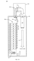
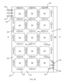
図1Aには、本発明に係る部品冷却システム100の例示的な実施形態が示されている。この部品冷却システム100は、筐体102と、空気冷却システム104と、2つの機器ラック106a,106bとを備える。
FIG. 1A illustrates an exemplary embodiment of a
少なくとも1つの実施形態において、空気冷却システム104は、筐体102の頂部かつその外部に設置してもよい。空気冷却システム104は、筐体102の頂部に位置する少なくとも1つの温風ポート110を介して筐体102から温かい空気108を受け取り、少なくとも1つの空気冷却ユニット112を介して受け取った温かい空気108を通過させることで、この受け取った温かい空気108を冷却してもよい。空気冷却ユニット112によって生成された冷たい空気114は、筐体102の頂部に位置する少なくとも1つの冷風ポート116を介して筐体102へと再び搬送される。例示的な実施形態を説明する図において、冷たい空気114の流れは、無地の矢印で示されており、温められた空気108の流れは、網掛けした矢印で示されている。
In at least one embodiment, the
冷風ポート116に取り付けられた冷風ダクト118は、筐体の床に向かって筐体102内へと少なくとも部分的に延びている。冷風ダクト118は、筐体102の上部において、冷却された空気114を温かい空気108から分離して、温かい空気108と冷たい空気114とが混ざらないようにする。このように温かい空気を冷たい空気から分離することにより、エア部品冷却システム100全体としての総合熱効率を向上させることができる。
A
少なくとも1つの実施形態において、冷風ダクト118の出口は、床から天井までの距離の40%から60%の範囲内に設けてもよい。しかし、他の実施形態において、冷風ダクトの出口を、床から天井までの他の範囲に設けることもできる。前記冷風ダクトは、布や軟質プラスチックなどの可撓性材料から作成してもよい。このような可撓性の材料は、筐体内で作業する人が誤って冷風ダクト118にぶつかってしまった場合に、その安全を保障するために好都合である。
In at least one embodiment, the outlet of the
各機器ラック106a,106bは、スタック配列で構成された2つ以上の放熱部品120を有する。各ラック106a,106bは、前面開口部と、後面開口部とを有する。この前面開口部は各放熱部品120の前部を露出させ、後面開口部は各放熱部品120の後部を露出させる。放熱部品120は、熱エネルギーの放散が可能な任意の装置を備えていてもよい。例示的な実施形態において、前記放熱部品は、バッテリモジュールまたは他の蓄電要素を備えていてもよい。各機器ラック106a,106bは、このようなバッテリモジュールを3つ以上備えていてもよい。幾つかの実施形態において、前記放熱部品は、1セットのバッテリモジュールを制御し、調整し、かつ他の方法で管理するバッテリ管理モジュールを備えていてもよい。
Each
各ラック106a,106bは、ラック底部に配置された送風装置122をさらに備える。送風装置122は、放熱部品と同様の専有面積を有するモジュールを備えていてもよく、これにより、放熱部品120を機器ラックに取り付けるために用いられるものと同様の取付用具を用いて前記送風装置をラックに取り付けてもよい。また、送風装置122の他の形態要素を代替的に用いてもよい。送風装置122は、この分野で公知のように、回転可能な軸に取り付けられた一定間隔のブレードを有するファンをさらに備えていてもよい。このファンは、制御入力に応じて送風装置122を通る空気流の速度を変化させる可変速度ファンであってもよい。前記制御入力は、筐体102および/またはラック106内の1つ以上の温度センサに応じたものであってもよい。あるいは、送風装置122は、通路にわたって空気を流すための、この分野で公知の他の機構を備えていてもよい。
Each
幾つかの実施形態において、各ラック106a,106bの底部に配置された送風装置122は、放熱部品120を通る空気流を促進するためにラックに設けられた唯一の能動的な部品である。これらの実施形態においては、部品120を通る空気流を促進または他の方法でこれを補助するために、他のファンまたは送風装置を、個々の放熱部品内に配置する必要はない。
In some embodiments, the
送風装置122は、前記筐体の底部分(すなわち、前記筐体の床)から空気を吸引し、その空気を、各ラック106a,106bの後面開口部に設置された空気プレナム124へと送る。空気プレナム124は、2つ以上の放熱部品120のスタックの後ろに空気チャネル126を形成する被覆部である。空気プレナム124がラック102と接触する箇所は、気密または略気密に構成されているので、送風装置122が(空気チャネル126に空気を送ることで)空気プレナムを加圧するとき、加圧された前記空気の経路は、放熱部品120の後部の開口部を通り、放熱部品120の内部および/またはその周囲を通る経路のみである。
The
図1Aおよび図1Bの例示的な実施形態には、送風装置122がラック106a,106bの下から直接空気を吸引するように、送風装置122と筐体102の底部との間に空間を有するラック106a,106bが示されている。他の実施形態において、ラック106a,106bは、その下に空間を設けずに筐体の床に直接設置して、送風装置122がラックの下からではなく、ラック底部の前方から空気を吸引するようにしてもよい。このような代替的な実施形態の例は図1Dに示されている。
1A and 1B show the
図2Aは、ラック106aの後部に取り付けられた空気プレナム124を示す、機器ラック106aの斜視図である。図2Bは、前記空気プレナムが取り外された状態の機器ラック106aの斜視図である。図2Bでは、各放熱部品120の後部が見えており、種々のコネクタ202、制御機能部204(例えば、スイッチ、ボタンなど)、および空気入口206が示されている。なお、これらの構成は、ラックに設置された放熱部品の後部に見られる構成の種類の例示に過ぎず、限定を意図したものではないと理解されたい。
Figure 2A is a perspective view of the
送風装置122は、1つ以上の空気吹出し口208をさらに備えていてもよく、送風装置122は、前記プレナムがラック106aに取り付けられたときに形成される空気チャネル126へと、この空気吹出し口を介して冷たい空気を送る。
The
なお、例示的な実施形態における空気プレナム124は矩形のボックス状の物品として示されているものの、空気プレナム124は、本明細書に記載されるように、このプレナムが放熱部品120の後ろに封止された気密(または略気密)の空気チャネル126を形成する限り、他の形状としてもよいと理解されたい。さらに、(空気プレナム124がラック106aに取り付けられたときにラック106aと接する)空気プレナムの縁部210には、空気プレナム124とラック106aとの間のシールを強化するために、ガスケットまたは他のシール材が取り付けられていてもよいと理解されたい。
It should be understood that although the
再度図1Aを参照すると、送風装置122は、筐体の環境圧力の冷たい空気を筐体102の底部から吸引し、その冷たい空気を、空気プレナム124によって形成される空気チャネル126へと送ることで、空気プレナム124を加圧して筐体の環境圧力よりも高い圧力とする。加圧された前記空気プレナムは、各放熱部品120の内部またはその周囲を通って機器ラック106a,106bの間の領域にある放熱部品120の前部の低圧領域へと流れる空気流を生じさせる。
Referring again to FIG. 1A, the
放熱部品120は、吸気ポート、出口ポート、空気チャネル、通路、バッフル、および放熱部品120の内部またはその周囲を通して空気を効率的に通過させるための他の構成を有するように構成してもよい。一実施形態において、前記放熱部品の後部には、放熱部品120の後面に分散された1つ以上の吸気ポートを設けてもよい。別の実施形態において、前記放熱部品の後面の一方側に1つ以上の吸気ポートを設け、放熱部品120の前面の反対側に出口ポートを設けてもよい。
The
図2Cは、サブ部品221を有する放熱部品220の例示的な実施形態の横断面図である。図2Cには、部品220の内部を通る空気チャネル222が図示されており、この空気チャネルにより、空気流224は、空気プレナム226から後部の吸気ポート228を通り、チャネル222を通って出口ポート230へと通過して、放熱部品220の前部から出ることができる。分かりやすくするために、空気流224を示す図形(矢印)およびチャネル222の一部にのみ符号を付している。
Figure 2C is a cross-sectional view of an exemplary embodiment of a
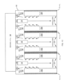
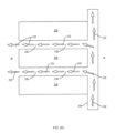
図2Dは、ラックに積み重ねられた3つの放熱部品230の例示的な実施形態の縦断面図であり、この実施形態は、空気が部品230の後方から当該部品の前方へと装置の間を通過するように構成されている。この例示的な実施形態では放熱部品が3つしか示されていないが、この構想は、より多くの放熱部品に対して適用することも可能である。図2Dには、空気プレナム234から、隣接する部品230の頂部238および底部240と、部品230が取り付けられているラックの側部(図示せず)とによって形成されるチャネル236を通る空気流232が示されている。
Figure 2D is a cross-sectional view of an exemplary embodiment of three
図2Cおよび図2Dに示される例示的な実施形態は、部品の冷却に空気流を用いることができる方法を示すためのものであり、限定を意図したものではない。上記構成の代わりに、またはそれに加えて、冷却される部品と関連付けられた他の構成の空気チャネルおよび通路を用いてもよい。さらに、図2Cに示されているような、部品を通して空気を通過させる構成を、図2Dに示されているような、部品の外側表面に沿って空気を通過させる構成と組み合わせて用いてもよい。 The exemplary embodiments shown in Figures 2C and 2D are intended to illustrate how airflow may be used to cool a component and are not intended to be limiting. Other configurations of air channels and passages associated with the component to be cooled may be used instead of or in addition to the above configurations. Furthermore, a configuration that passes air through a component, as shown in Figure 2C, may be used in combination with a configuration that passes air along the outer surface of the component, as shown in Figure 2D.
空気チャネル126からの冷たい空気は、この冷たい空気が部品120の内部を通過するときに、放熱部品120(および/または放熱部品120内のサブ部品)から放出された熱エネルギーを吸収することができ、これにより、放熱部品120を通過する空気の温度が上昇する。したがって、放熱部品120から出る空気の温度は、空気プレナムから部品120に入る空気の温度よりも高い。前記空気チャネル、経路、バッフル、および放熱部品120を通して空気を搬送する他の構成は、さらに、放熱部品120およびサブ部品から部品120を通過する空気へと熱エネルギーを効率的に伝達するように設計してもよい。
The cool air from the
放熱部品120から出る温かい空気は、空気冷却システム104によって生成される冷たい空気よりも密度が低いので、熱対流によって筐体102の頂部へと上昇する傾向がある。空気冷却システム104は、1つ以上の温風ポート110を介して、筐体102の頂部において温かい空気108を引き込み、この分野で公知の1つ以上の冷却ユニット112によって温かい空気108を冷却する。例示的な実施形態において、各冷却ユニットは、圧縮/膨張冷凍サイクルシステムであってもよいが、圧縮/膨張冷凍サイクルシステムの代わりに、またはそれに加えて、この分野で公知の他の冷却システムを用いてもよい。
The warm air exiting the
他の実施形態において、前記冷たい空気は、放熱部品122の中を流す代わりに(またはそれに加えて)、隣接する放熱部品122の対の間を通過させてもよい。
In other embodiments, the cool air may be passed between a pair of adjacent
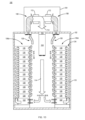
図1Aに示される例示的な実施形態では、2つの機器ラック106aおよび106bが図示されているが、本明細書に記載する構想は、図1Bの例示的な実施形態で示すように1つの機器ラックを有するものや、図1Cの例示的な実施形態で示すように2つ以上の機器ラック106a~106fを有するものにも適用可能であると理解されたい。図1Cの実施形態における特定の対のラックは、背面合わせで設けられたラックの一方のプレナムが、背面合わせで設けられたラックの他方のプレナムと隣接するように構成されている。
In the exemplary embodiment shown in FIG. 1A, two
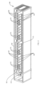
また、図1Aから図1Dに示された機器ラックは、一列のラックのうちの個々のラックを表していてもよいと理解されたい。例えば、図3は、図1Aの実施形態と一致する実施形態の斜視図であり、筐体内に平行な2列の機器ラックを有している。図3に示されているように、第1列302のラック304は、筐体308の一方の長辺の側壁306につけて配置されており、第2列310のラック304は、筐体308の他方の長辺の側壁312につけて配置されている。図3では、ラックの列が見えるように、筐体308の天井および冷却システムが取り外された状態で示されている。また、分かりやすくするために、一部のラック304にのみ符号を付している。図3の実施形態において、各列302,310のラック304は、各ラックの後部(すなわち、プレナム)が筐体の側壁306,312に隣接した状態で並べて配置されている。冷風ダクト318の対は、筐体の天井における対応する冷風ポートとは連結されていない状態で、ラック304の列302,310の間で筐体の下方へと延びるように示されている。図3に示された筐体内のラックの列についての構想は、例えば図1Cに示されるような2つ以上の列を有する実施形態に適用することも可能である。
It should also be understood that the equipment racks shown in Figures 1A-1D may represent individual racks in a row of racks. For example, Figure 3 is a perspective view of an embodiment consistent with that of Figure 1A having two parallel rows of equipment racks within an enclosure. As shown in Figure 3, a
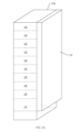
図4Aは、本発明に従って構成された1つの例示的な機器ラック402の正面図である。この例示的な実施形態では、16個のバッテリモジュール404と、1つのバッテリ管理モジュール405とがスタック状に配置され、1つの送風装置モジュール406がラック402の底部に設けられている。
Figure 4A is a front view of an
図4Bは、図4Aに示されたラック402の底部をより詳細に示す図である。図4bには4つのバッテリモジュール404が示されており、送風装置モジュール406は、ラック402から部分的に取り出された状態で示されている。各モジュール404,406は、交換、修理、又は他の必要なメンテナンスのために個別に取り出すことができる。
Figure 4B is a more detailed view of the bottom of the
図4Cには、部分的に分解された送風装置モジュール406が示されており、カバー408を取り外し、電気回転式のファンアセンブリ410を露出させた状態となっている。ファンアセンブリ410は、送風装置モジュール406の底部の第1開口部412から空気を吸引し、第2開口部414を通して空気プレナム(図示せず)へと空気を送る。
FIG. 4C shows the
開示された各実施形態において、各部品またはモジュールに対して1つの送風装置を用いるのではなく、各ラックに対して1つの送風装置を使用することにより、効率性および信頼性が高く、より長い寿命が得られる比較的高品質な送風装置を使用しつつも、コストを抑えたシステムとすることができる。このため、空気プレナムの寸法は、空気プレナムの高さにわたる圧力低下が、各部品または各モジュールにわたる圧力低下よりも低くなるような寸法となっている。通常、部品またはモジュールを通る空気流に対する抵抗は一定であるが、部品またはモジュールを通る相対的な流れを制御するために変化させてもよい。 In the disclosed embodiments, the use of one blower per rack, rather than one blower per component or module, allows for a lower cost system while still using higher quality blowers that are more efficient, more reliable, and have a longer lifespan. The air plenum is thus sized such that the pressure drop across the height of the air plenum is lower than the pressure drop across each component or module. Typically, the resistance to airflow through the components or modules is constant, but may be varied to control the relative flow through the components or modules.
本発明について、その例示的な実施形態を参照しながら具体的に図示および説明を行ったが、当業者は、添付の請求の範囲に含まれる本発明の範囲から逸脱することなく、本発明において形状および細部に様々な変更を施すことができるということを理解されたい。
なお、本発明は、実施の態様として以下の内容を含む。
[態様1]
筐体と、
筐体天井の温風ポートを介して前記筐体内から温かい空気を受け取り、前記温かい空気を冷却して冷却された空気を生成し、前記筐体天井の冷風ポートを介して前記筐体に前記冷却された空気を供給するように構成された空気冷却システムと、
前記筐体内に配置された1つ以上のラックと、
を備え、
各ラックは、
(i)前記ラックに設置された放熱部品スタックと、
(ii)前記ラックの後面開口部を覆うことで、前記ラックの各前記部品の後部に沿って空気チャネルを形成する空気プレナムと、
(iii)前記ラックの底部に配置された送風装置であって、前記ラックの外部から空気を吸引し、前記空気プレナムへと前記空気を送ることで、前記空気プレナムを加圧する送風装置と、を有し、
(iv)前記放熱部品スタックは、加圧された前記空気プレナムから前記放熱部品の内部またはその周囲を通り、前記部品の前方の前記ラックの外部へと空気流を案内するように構成されており、
前記放熱部品スタックは、各前記部品の前記後部にある加圧された前記空気プレナムから各前記部品の前部への空気流を促進するように構成されている、
部品冷却用のシステム。
[態様2]
態様1に記載のシステムにおいて、前記放熱部品スタックは、内部を通る空気流路を有することによって前記空気流を促進するように構成された部品を含むシステム。
[態様3]
態様2に記載のシステムにおいて、前記放熱部品の第1の側には、前記部品の前記後部の開口部が設けられており、前記部品内の1つ以上のチャネルは、前記部品の前記第1の側から前記部品の第2の側へ、かつ前記部品の前記後部から前記部品の前記前部へ、前記部品の内部を通って前記空気流路を案内するように構成されているシステム。
[態様4]
態様1に記載のシステムにおいて、前記放熱部品スタックは、隣接する部品の対の間に空気流路を有することによって前記空気流を促進するように構成されているシステム。
[態様5]
態様1に記載のシステムにおいて、前記送風装置は、可変速度ファンであるシステム。
[態様6]
態様1に記載のシステムにおいて、前記1つ以上のラックのそれぞれについて、前記送風装置は、前記空気流を促進するために前記ラックに設けられた唯一の能動的な部品であるシステム。
[態様7]
態様1に記載のシステムにおいて、前記部品スタックは、少なくとも3つのバッテリモジュール部品を含むスタックを備えるシステム。
[態様8]
態様7に記載のシステムにおいて、前記部品スタックは、バッテリ管理モジュール部品を含むシステム。
[態様9]
態様1に記載のシステムにおいて、前記空気冷却システムは、前記筐体の頂部かつその外側に取り付けられているシステム。
[態様10]
態様1に記載のシステムにおいて、前記筐体内で前記冷風ポートに取り付けられ、かつ前記冷風ポートから前記筐体の床へと延びる冷風ダクトをさらに備え、前記冷風ダクトは、前記筐体の前記床の上方かつ前記1つ以上のラックの前面開口部の側に設けられた出口を有するシステム。
[態様11]
態様10に記載のシステムにおいて、前記出口は、前記床から前記天井までの距離の40%から60%の範囲内で前記床の上方に設けられているシステム。
[態様12]
態様10に記載のシステムにおいて、前記冷風ダクトは、可撓性材料から形成されているシステム。
[態様13]
態様1に記載のシステムにおいて、前記1つ以上のラックは、前記筐体の第1の側に沿って並べて配置された第1のラックの列と、前記筐体の第2の側に沿って並べて配置された第2のラックの列とを有し、各前記ラックの前記空気プレナムは、各筐体側部にそれぞれ隣接しているシステム。
[態様14]
態様1に記載のシステムにおいて、前記1つ以上のラックは、第1のラックの列と、第2のラックの列とを有し、前記第1のラックの列および前記第2のラックの列は、前記第1の列の各ラックの前記空気プレナムが、前記第2のラックの列のうちの1つのラックの空気プレナムとそれぞれ隣接するように背面合わせで配置されているシステム。
[態様15]
放熱部品のラックの冷却方法であって、
空気を冷却することと、
前記ラックの前方に形成された空間領域に前記空間領域の上方から前記空気を案内することと、
前記ラックの底部分に配置された送風装置を用いて、前記ラックの前方に形成された前記空間領域から前記ラックの後部のプレナムへと冷たい空気を移動させて、前記プレナムを加圧することと、
前記プレナムから前記ラック内の前記放熱部品の周囲またはその内部を通して前記ラックの前方の前記空間領域へと、前記プレナムの圧力のみによって空気を流すことと、
前記ラックの前方に形成された前記空間領域の上部から温められた空気を取り込み、前記温められた空気を冷却することとを含む方法。
[態様16]
態様14に記載の方法において、前記部品の後部の開口部から前記部品の前部における開口部まで各前記放熱部品の内部を通るように形成された通路に、前記プレナムから空気を流すことをさらに含む方法。
[態様17]
態様14に記載の方法において、隣接する放熱部品の間における、前記隣接する部品の後部から前記隣接する部品の前部までの空間に、前記プレナムから空気を流すことをさらに含む方法。
[態様18]
態様17に記載の方法において、前記空気は、前記ラックおよび前記空間領域を囲む筐体の頂部に配置された空気冷却システムによって冷却される方法。
[態様19]
態様17に記載の方法において、前記冷風ポートから前記筐体の床に向かって延びる冷風ダクトであって、前記1つ以上のラックの前面開口部の側において前記床の上方に出口が設けられた冷風ダクトを介して前記筐体に冷却された空気を供給することをさらに含む方法。
[態様20]
態様17に記載の方法において、前記筐体の第1の側に沿って第1のラックの列を配置することと、前記筐体の第2の側に沿って第2のラックの列を配置することとをさらに含み、各前記ラックの列は、それぞれの筐体側部に隣接する空気プレナムと、他のラックの前面開口部に面する側に前面開口部とを有する方法。
[態様21]
態様20に記載の方法において、前記第1のラックの列と前記第2のラックの列との間において前記筐体に前記冷却された空気を供給することをさらに含む方法。
[態様22]
複数の放熱部品の冷却方法であって、
1つ以上のラック内で、前記複数の部品をスタック構造に配置することであって、各ラックに空気プレナムが取り付けられており、前記空気プレナムは、前記ラックの後面開口部を覆うことで、前記ラックの各前記部品の外側表面の周囲に空気チャネルを形成している、ことと、
前記1つ以上のラックを筐体内に収容することと、
天井の温風ポートを介して前記筐体内から温かい空気を受け取り、前記温かい空気を冷却して冷却された空気を生成し、前記天井の冷風ポートを介して前記筐体内に前記冷却された空気を提供することと、
前記ラックの外部かつ底部における位置から前記冷却された空気を吸引し、
前記空気プレナムに前記冷却された空気を送って前記空気プレナムを加圧することと、を含む方法。
[態様23]
態様22に記載の方法において、前記放熱部品の後部の開口部から前記部品の前部の開口部まで各部品を通るように形成された通路に、前記プレナムから空気を流すことをさらに含む方法。
[態様24]
態様22に記載の方法において、隣接する部品の間における、前記隣接する部品の後部から前記隣接する部品の前部までの空間に、前記プレナムから空気を流すことをさらに含む方法。
[態様25]
態様22に記載の方法において、冷風ダクトが、前記冷風ポートから前記筐体の床に向かって延びており、前記冷風ダクトは、前記1つ以上のラックの前面開口部の側において前記床の上方に設けられた出口を有している方法。
[態様26]
ラックであって、(i)当該ラックに取り付けられた放熱部品スタックと、(ii)前記ラックの後部に設けられて、前記ラックの各前記部品の後部に沿って空気チャネルを形成している空気プレナムと、(iii)前記ラックの底部に配置された送風装置であって、前記ラックの外部から空気を吸引し、前記空気プレナムへと前記空気を送ることで、前記空気プレナムを加圧するように構成された送風装置とを有するラックを備え、
前記部品スタックは、各前記部品の前記後部の加圧された前記空気プレナムから各前記部品の前部への空気流を促進するように構成されている、部品冷却用のシステム。
[態様27]
態様26に記載の方法において、前記放熱部品スタックは、その内部を通る空気流路を有することによって前記空気流を促進するように構成された部品を含む方法。
[態様28]
態様26に記載の方法において、前記放熱部品の第1の側には、前記部品の前記後部の開口部が設けられており、前記部品内の1つ以上のチャネルは、前記部品の前記第1の側から前記部品の第2の側へと、そして前記部品の前記後部から前記部品の前記前部へと、前記部品の中を通って前記空気流路を案内するように構成されている方法。
[態様29]
筐体と、
筐体天井の温風ポートを介して前記筐体内から温かい空気を受け取り、前記温かい空気を冷却して冷却された空気を生成し、前記筐体の床に向かって前記筐体内へと延びる冷風ダクトを介して前記筐体に前記冷却された空気を供給するように構成された空気冷却システムであって、前記冷風ダクトは、前記床から前記天井までの距離の40%から60%の範囲内で前記筐体の床の上方に設けられた出口を有する、空気冷却システムと、
前記筐体内に配置されたラックであって、前記筐体の第1の側に沿って配置された第1のラックの列と、前記筐体の第2の側に沿って配置された第2のラックの列とを有し、各ラックが、筐体側部にそれぞれ隣接した空気プレナムと、空間領域に面する前部とを有する、ラックと、
を備え、
各ラックは、
(i)前記ラックに設置されたスタック配列の少なくとも3つのバッテリ部品と、
(ii)前記ラックの後面開口部に設けられて、前記ラック内の各前記バッテリ部品の後部に沿って空気チャネルを形成している空気プレナムと、
(iii)前記ラックの底部に配置された送風装置であって、前記空間領域から空気を吸引し、前記空気プレナムへと前記空気を送ることで、前記空気プレナムを加圧するように構成された送風装置と、を有し、
前記スタック配列のバッテリ部品は、各前記部品の前記後部の加圧された前記空気プレナムから各前記部品の前部へと、そしてラックの列の間の前記空間領域への空気流を促進するように構成されている、
バッテリ部品冷却用のシステム。
While the present invention has been particularly shown and described with reference to illustrative embodiments thereof, it will be understood by those skilled in the art that various changes in form and detail can be made therein without departing from the scope of the invention contained in the appended claims.
The present invention includes the following embodiments.
[Aspect 1]
A housing and
an air cooling system configured to receive warm air from within the enclosure through a hot air port in a ceiling of the enclosure, to cool the warm air to generate cooled air, and to supply the cooled air to the enclosure through a cold air port in the ceiling of the enclosure;
one or more racks disposed within the enclosure;
Equipped with
Each rack is
(i) a heat dissipation component stack mounted on the rack;
(ii) an air plenum covering a rear opening of the rack to form an air channel along a rear of each of the components of the rack;
(iii) a blower disposed at a bottom of the rack, the blower sucking air from outside the rack and blowing the air into the air plenum to pressurize the air plenum;
(iv) the heat dissipation component stack is configured to direct airflow from the pressurized air plenum, through or around the heat dissipation components, and out of the rack in front of the components;
the heat dissipation component stack is configured to facilitate airflow from the pressurized air plenum at the rear of each of the components to the front of each of the components;
A system for cooling components.
[Aspect 2]
2. The system of
[Aspect 3]
3. The system of claim 2, wherein a first side of the heat dissipation component defines an opening at the rear of the component, and one or more channels within the component are configured to guide the air flow path through the interior of the component from the first side of the component to a second side of the component and from the rear of the component to the front of the component.
[Aspect 4]
2. The system of
[Aspect 5]
2. The system of
[Aspect 6]
2. The system of
[Aspect 7]
2. The system of
[Aspect 8]
8. The system of claim 7, wherein the component stack includes a battery management module component.
[Aspect 9]
2. The system of
[Aspect 10]
The system of
[Aspect 11]
11. The system of
[Aspect 12]
11. The system of
[Aspect 13]
In the system described in
[Aspect 14]
2. The system of
[Aspect 15]
1. A method for cooling a rack of heat dissipating components, comprising:
Cooling the air;
Guiding the air from above a spatial region formed in front of the rack;
using a blower located at the bottom of the rack to move cool air from the volume defined in front of the rack to a plenum at the rear of the rack to pressurize the plenum;
directing air from the plenum, around or through the heat dissipation components in the rack, to the volume in front of the rack under only the pressure of the plenum;
and taking in heated air from an upper portion of the volume defined in front of the rack and cooling the heated air.
[Aspect 16]
15. The method of claim 14, further comprising: channeling air from the plenum through a passageway formed through an interior of each of the heat dissipation components from an opening at a rear of the component to an opening at a front of the component.
[Aspect 17]
15. The method of claim 14, further comprising flowing air from the plenum into a space between adjacent heat dissipation components from a rear of the adjacent components to a front of the adjacent components.
[Aspect 18]
20. The method of claim 17, wherein the air is cooled by an air cooling system located on top of an enclosure that encloses the rack and the spatial area.
[Aspect 19]
A method as described in claim 17, further comprising supplying cooled air to the enclosure through a cold air duct extending from the cold air port toward the floor of the enclosure and having an outlet above the floor on the side of the front opening of the one or more racks.
[Aspect 20]
The method of claim 17, further comprising arranging a first row of racks along a first side of the enclosure and arranging a second row of racks along a second side of the enclosure, each row of racks having an air plenum adjacent to a respective enclosure side and a front opening on a side facing the front opening of the other rack.
[Aspect 21]
21. The method of
[Aspect 22]
A method for cooling a plurality of heat dissipation components, comprising:
arranging the plurality of components in a stack configuration in one or more racks, each rack having an air plenum attached thereto, the air plenum covering a rear opening of the rack to form an air channel around an exterior surface of each of the components on the rack;
housing the one or more racks within an enclosure;
receiving warm air from within the housing via a hot air port in the ceiling, cooling the warm air to generate cooled air, and providing the cooled air into the housing via a cold air port in the ceiling;
drawing the cooled air from a location at the exterior and bottom of the rack;
and passing the cooled air through the air plenum to pressurize the air plenum.
[Aspect 23]
23. The method of claim 22, further comprising channeling air from the plenum through a passageway formed through each component from an opening in a rear of the heat dissipation component to an opening in a front of the component.
[Aspect 24]
23. The method of claim 22, further comprising flowing air from the plenum into a space between adjacent components from a rear of the adjacent components to a front of the adjacent components.
[Aspect 25]
23. The method according to claim 22, wherein a cold air duct extends from the cold air port toward the floor of the enclosure, and the cold air duct has an exit provided above the floor on the side of the front opening of the one or more racks.
[Aspect 26]
a rack having (i) a heat dissipation component stack mounted to the rack; (ii) an air plenum disposed at a rear of the rack forming an air channel along a rear of each of the components on the rack; and (iii) an air blower disposed at a bottom of the rack configured to draw air from outside the rack and blow the air into the air plenum, thereby pressurizing the air plenum;
11. A system for cooling components, wherein the component stack is configured to facilitate airflow from the pressurized air plenum at the rear of each of the components to a front of each of the components.
[Aspect 27]
27. The method of claim 26, wherein the heat dissipation component stack includes components configured to facilitate the airflow by having air passages therethrough.
[Aspect 28]
27. The method of claim 26, wherein a first side of the heat dissipation component defines an opening at the rear of the component, and one or more channels within the component are configured to guide the air flow path through the component from the first side of the component to a second side of the component and from the rear of the component to the front of the component.
[Aspect 29]
A housing and
an air cooling system configured to receive warm air from within an enclosure through a hot air port in a ceiling of the enclosure, cool the warm air to generate cooled air, and supply the cooled air to the enclosure through a cold air duct extending into the enclosure toward a floor of the enclosure, the cold air duct having an outlet provided above the floor of the enclosure within a range of 40% to 60% of a distance from the floor to the ceiling;
racks disposed within the enclosure, the racks having a first row of racks disposed along a first side of the enclosure and a second row of racks disposed along a second side of the enclosure, each rack having an air plenum adjacent a respective enclosure side and a front facing a volume area;
Equipped with
Each rack is
(i) at least three battery components in a stacked arrangement mounted on the rack;
(ii) an air plenum disposed at a rear opening of the rack to form an air channel along a rear of each of the battery components within the rack;
(iii) a blower disposed at a bottom of the rack, the blower configured to draw air from the spatial region and blow the air into the air plenum to pressurize the air plenum;
the stacked battery components are configured to facilitate air flow from the pressurized air plenum at the rear of each of the components to the front of each of the components and into the space between the rows of racks;
A system for cooling battery components.
Claims (27)
前記筐体の天井部の温風ポートを介して前記筐体内から温かい空気を受け取り、前記受け取った温かい空気を冷凍冷却システム内を通過させることで、冷却された空気を生成し、前記筐体の天井部の冷風ポートを介して前記筐体に前記冷却された空気を供給するように構成された空気冷却システムと、
前記筐体内に配置された1つ以上のラックと、
を備え、
各ラックは、
(i)前記ラックに設置された放熱部品のスタックと、
(ii)前記ラックの後面開口部を覆うことで、前記ラックの各前記放熱部品の後部に沿って空気チャネルを形成する空気プレナムと、
(iii)前記ラックの底部に配置された送風装置であって、前記ラックの外部から空気を吸引し、前記空気プレナムへと前記空気を送ることで、前記空気プレナムを加圧する送風装置と、を有し、
(iv)前記放熱部品のスタックは、加圧された前記空気プレナムから前記放熱部品の内部またはその周囲を通り、前記放熱部品の前側に前記ラックの外部へと空気流を案内するように構成されており、
前記放熱部品のスタックは、各前記放熱部品の後部において加圧された前記空気プレナムから、前記放熱部品の前部への空気流を促進するように構成され、
前記筐体内で前記冷風ポートに取り付けられ、かつ前記冷風ポートから前記筐体の床に向かって筐体内部へと延びる冷風ダクトが、前記筐体の前記天井部に位置する温かい空気に対して、前記冷風ダクト内を流れる前記冷却された空気を分離できるように構成され、
前記冷風ダクトは、前記筐体の前記床の上方に配置されると共に前記筐体の床へと前記冷却された空気を放出するために設けられた出口を有し、前記各ラックの前記底部に配置された送風装置によって、前記筐体の前記床から前記冷却された空気を吸引し、当該前記冷却された空気をそれぞれの前記空気プレナムへと送るように構成されている、
部品冷却用のシステム。 A housing and
an air cooling system configured to receive warm air from within the housing through a hot air port in a ceiling portion of the housing, generate cooled air by passing the received warm air through a refrigeration and cooling system, and supply the cooled air to the housing through a cold air port in the ceiling portion of the housing;
one or more racks disposed within the enclosure;
Equipped with
Each rack is
(i ) a stack of heat dissipation components mounted on the rack;
(ii) an air plenum covering a rear opening of the rack to form an air channel along a rear of each of the heat dissipation components of the rack;
(iii) a blower disposed at a bottom of the rack, the blower sucking air from outside the rack and blowing the air into the air plenum to pressurize the air plenum ;
(iv ) the stack of heat dissipation components is configured to direct airflow from the pressurized air plenum through or around the heat dissipation components to the front of the heat dissipation components and out of the rack ;
the stack of heat dissipation components is configured to promote airflow from the pressurized air plenum at the rear of each heat dissipation component to the front of the heat dissipation component ;
a cold air duct attached to the cold air port within the housing and extending from the cold air port toward the floor of the housing into the housing is configured to separate the cooled air flowing through the cold air duct from the warm air located in the ceiling of the housing;
The cold air duct is disposed above the floor of the enclosure and has an outlet provided for discharging the cooled air to the floor of the enclosure, and is configured to suck the cooled air from the floor of the enclosure by a blower disposed at the bottom of each of the racks and send the cooled air to each of the air plenums.
A system for cooling components.
空気を冷却することと、
前記ラックの前側に形成された空間領域の上方から、前記空間領域へと、前記冷却された空気を案内することと、
前記冷却された空気を筐体の床へ向かって放出することと、
前記ラックの底部に配置された送風装置によって、前記筐体の前記床から前記冷却された空気を吸引することと、
前記ラックの前側に形成された前記空間領域から前記ラックの後部のプレナムへと、吸引された冷却空気を移動させて、前記プレナムを加圧することと、
前記プレナムから前記ラック内の前記放熱部品の周囲またはその内部を通して前記ラックの前側の前記空間領域へと、前記プレナムの圧力によって前記吸引された冷却空気を流すことと、
前記筐体の天井部に位置する温かい空気と、前記筐体の前記天井部の冷風ポートから前記筐体の床に向かって延びると共に、前記筐体の前記床の上方に出口が設けられた冷風ダクト内を流れる前記冷却された空気とを分離することと、
前記ラックの前記前側に形成された前記空間領域の上部から温められた空気を取り込むこととを含む方法。 1. A method for cooling a rack of heat dissipating components, comprising:
Cooling the air;
Guiding the cooled air from above a space area formed in front of the rack into the space area;
Discharging the cooled air towards a floor of the enclosure;
Suctioning the cooled air from the floor of the enclosure by a blower disposed at the bottom of the rack ;
moving the drawn cooling air from the volume defined in front of the rack to a plenum at the rear of the rack and pressurizing the plenum;
directing the drawn cooling air from the plenum through or around the heat dissipation components in the rack to the space in front of the rack by pressure in the plenum ;
Separating the warm air located in the ceiling of the housing from the cooled air flowing through a cold air duct extending from a cold air port in the ceiling of the housing toward a floor of the housing and having an outlet above the floor of the housing;
and drawing in heated air from an upper portion of the volume defined on the front side of the rack.
1つ以上のラック内で、前記複数の放熱部品をスタック構造に配置することであって、各ラックに空気プレナムが取り付けられており、前記空気プレナムは、前記ラックの後面開口部を覆うことで、前記ラックの各前記放熱部品の外側表面の周囲に空気チャネルを形成している、ことと、
前記1つ以上のラックを筐体内に収容することと、
天井部の温風ポートを介して前記筐体内から温かい空気を受け取り、前記温かい空気を冷却して冷却された空気を生成し、前記天井部の冷風ポートから前記筐体の床に向かって延びると共に、前記床の上方に設けられた出口を有する冷風ダクトを介して、前記筐体内の床に、前記冷却された空気を提供することと、
各前記ラック内の底部に配置された送風装置によって、前記筐体内の前記床から前記冷却された空気を吸引し、前記空気プレナムに前記冷却された空気を送って前記空気プレナムを加圧することと、を含む方法。 A method for cooling a plurality of heat dissipation components, comprising:
arranging the plurality of heat dissipation components in a stack configuration in one or more racks, each rack having an air plenum attached thereto, the air plenum covering a rear opening of the rack to form an air channel around an exterior surface of each of the heat dissipation components of the rack;
housing the one or more racks within an enclosure;
receiving warm air from within the housing through a hot air port in a ceiling portion, cooling the warm air to generate cooled air, and providing the cooled air to a floor within the housing through a cold air duct that extends from the cold air port in the ceiling portion toward a floor of the housing and has an outlet provided above the floor;
and drawing the cooled air from the floor of the enclosure with a blower located at the bottom of each of the racks and directing the cooled air into the air plenum to pressurize the air plenum.
前記筐体の天井部の温風ポートを介して前記筐体内から温かい空気を受け取り、前記温かい空気を冷却して冷却された空気を生成し、前記筐体の前記天井部の冷風ポートを介して前記筐体に前記冷却された空気を供給するように構成された空気冷却システムと、
ラックであって、(i)当該ラックに設置された放熱部品のスタックと、(ii)前記ラックの後部に設けられて、前記ラックの各前記放熱部品の後部に沿って空気チャネルを形成している空気プレナムと、(iii)前記ラックの底部に配置された送風装置であって、前記ラックの外部から空気を吸引し、前記空気プレナムへと前記空気を送ることで、前記空気プレナムを加圧するように構成された送風装置とを有するラックとを備え、
前記筐体内で前記冷風ポートに取り付けられ、かつ前記冷風ポートから前記筐体の床に向かって筐体内部へと延びる冷風ダクトが、前記筐体の前記天井部に位置する温かい空気に対して、前記冷風ダクト内を流れる前記冷却された空気を分離できるように構成され、
前記冷風ダクトは、前記筐体の前記床の上方に配置されると共に前記筐体の床へと前記冷却された空気を放出するために設けられた出口を有し、前記各ラックの前記底部に配置された前記送風装置によって、前記筐体の前記床部から前記冷却された空気を吸引し、前記冷却された空気をそれぞれの前記空気プレナムへと送るように構成されている部品冷却用のシステム。 A housing and
an air cooling system configured to receive warm air from within the housing through a hot air port in a ceiling portion of the housing, cool the warm air to generate cooled air, and supply the cooled air to the housing through a cold air port in the ceiling portion of the housing;
A rack having: (i) a stack of heat dissipation components mounted on the rack; (ii) an air plenum disposed at a rear of the rack forming an air channel along a rear of each of the heat dissipation components on the rack; and (iii) an air blower disposed at a bottom of the rack configured to draw air from outside the rack and blow the air into the air plenum, thereby pressurizing the air plenum;
a cold air duct attached to the cold air port within the housing and extending from the cold air port toward the floor of the housing into the housing is configured to separate the cooled air flowing through the cold air duct from the warm air located in the ceiling of the housing;
The cold air duct is positioned above the floor of the enclosure and has an outlet for discharging the cooled air to the floor of the enclosure, and the blower device is positioned at the bottom of each rack, and is configured to draw in the cooled air from the floor of the enclosure and send the cooled air to each of the air plenums.
前記筐体の天井部の温風ポートを介して前記筐体内から温かい空気を受け取り、前記温かい空気を冷却して冷却された空気を生成し、前記筐体の床に向かって前記筐体内へと延びる冷風ダクトを介して前記筐体に前記冷却された空気を供給するように構成された空気冷却システムであって、前記冷風ダクトは、前記床から前記天井部までの距離の40%から60%の範囲内で前記筐体の前記床の上方に設けられた出口を有する、空気冷却システムと、
前記筐体内に配置されたラックであって、前記筐体の第1の側に沿って配置された第1のラックの列と、前記筐体の第2の側に沿って配置された第2のラックの列とを有し、各前記ラックが、筐体側部にそれぞれ隣接した空気プレナムと、空間領域に面する前部とを有する、ラックと、
を備え、
各前記ラックは、
(i)前記ラックに設置されたスタック配列の少なくとも3つのバッテリ部品と、
(ii)前記ラックの後面開口部に設けられて、前記ラック内の各前記バッテリ部品の後部に沿って空気チャネルを形成している空気プレナムと、
(iii)前記ラックの底部に配置された送風装置であって、前記空間領域から空気を吸引し、前記空気プレナムへと前記空気を送ることで、前記空気プレナムを加圧するように構成された送風装置と、
を有し、
前記スタック配列のバッテリ部品は、各前記バッテリ部品の前記後部の加圧された前記空気プレナムから各前記バッテリ部品の前部へと、そして前記ラックの列の間の前記空間領域への空気流を促進するように構成されており、
前記冷風ダクトは、当該冷風ダクト内を流れる前記冷却された空気を、前記筐体の天井部に位置する前記温かい空気から分離できるように、かつ前記冷却された空気を前記筐体の前記床へと放出するように構成され、
各前記ラックの前記底部に配置された送風装置によって、前記筐体の前記床から前記冷却された空気を吸引し、当該冷却された空気をそれぞれの前記空気プレナムへと送るように構成されている、
バッテリ部品冷却用のシステム。 A housing and
an air cooling system configured to receive warm air from within the enclosure through a hot air port in a ceiling of the enclosure, cool the warm air to generate cooled air, and supply the cooled air to the enclosure through a cold air duct extending into the enclosure toward a floor of the enclosure, the cold air duct having an outlet provided above the floor of the enclosure within a range of 40% to 60% of a distance from the floor to the ceiling;
racks disposed within the enclosure, the racks including a first row of racks disposed along a first side of the enclosure and a second row of racks disposed along a second side of the enclosure, each rack having an air plenum adjacent a respective enclosure side and a front facing a volume area;
Equipped with
Each of the racks is
(i ) at least three battery components in a stacked arrangement mounted on the rack;
(ii) an air plenum disposed at a rear opening of the rack to form an air channel along a rear of each of the battery components within the rack;
(iii) a blower disposed at a bottom of the rack, the blower configured to draw air from the spatial region and blow the air into the air plenum to pressurize the air plenum; and
having
the stacked battery components are configured to promote air flow from the pressurized air plenum at the rear of each battery component to the front of each battery component and into the space between the rows of racks;
the cold air duct is configured to separate the cooled air flowing through the cold air duct from the warm air located in a ceiling of the enclosure and to discharge the cooled air to the floor of the enclosure;
a blower disposed at the bottom of each of the racks configured to draw the cooled air from the floor of the enclosure and deliver the cooled air to each of the air plenums;
A system for cooling battery components.
Applications Claiming Priority (4)
| Application Number | Priority Date | Filing Date | Title |
|---|---|---|---|
| US15/397,256 | 2017-01-03 | ||
| US15/397,256 US11978875B2 (en) | 2017-01-03 | 2017-01-03 | System for cooling components arranged within an enclosure |
| PCT/US2017/066952 WO2018128783A1 (en) | 2017-01-03 | 2017-12-18 | A system for cooling components arranged within an enclosure |
| JP2019536221A JP7261161B2 (en) | 2017-01-03 | 2017-12-18 | A system that cools the parts placed inside the enclosure |
Related Parent Applications (1)
| Application Number | Title | Priority Date | Filing Date |
|---|---|---|---|
| JP2019536221A Division JP7261161B2 (en) | 2017-01-03 | 2017-12-18 | A system that cools the parts placed inside the enclosure |
Publications (2)
| Publication Number | Publication Date |
|---|---|
| JP2023090735A JP2023090735A (en) | 2023-06-29 |
| JP7585380B2 true JP7585380B2 (en) | 2024-11-18 |
Family
ID=61007793
Family Applications (2)
| Application Number | Title | Priority Date | Filing Date |
|---|---|---|---|
| JP2019536221A Active JP7261161B2 (en) | 2017-01-03 | 2017-12-18 | A system that cools the parts placed inside the enclosure |
| JP2023062947A Active JP7585380B2 (en) | 2017-01-03 | 2023-04-07 | A system for cooling components placed inside an enclosure |
Family Applications Before (1)
| Application Number | Title | Priority Date | Filing Date |
|---|---|---|---|
| JP2019536221A Active JP7261161B2 (en) | 2017-01-03 | 2017-12-18 | A system that cools the parts placed inside the enclosure |
Country Status (11)
| Country | Link |
|---|---|
| US (2) | US11978875B2 (en) |
| EP (1) | EP3545733B1 (en) |
| JP (2) | JP7261161B2 (en) |
| KR (1) | KR102579774B1 (en) |
| CN (1) | CN110235535A (en) |
| ES (1) | ES3032617T3 (en) |
| HR (1) | HRP20250854T1 (en) |
| HU (1) | HUE072295T2 (en) |
| PL (1) | PL3545733T3 (en) |
| RS (1) | RS67010B1 (en) |
| WO (1) | WO2018128783A1 (en) |
Families Citing this family (13)
| Publication number | Priority date | Publication date | Assignee | Title |
|---|---|---|---|---|
| WO2016053227A1 (en) * | 2014-09-29 | 2016-04-07 | Hewlett Packard Enterprise Development Lp | Fan controlled ambient air cooling of equipment in a controlled airflow environment |
| JP6678302B2 (en) * | 2015-07-24 | 2020-04-08 | パナソニックIpマネジメント株式会社 | Temperature control unit, temperature control system, vehicle |
| US10736231B2 (en) * | 2016-06-14 | 2020-08-04 | Dell Products L.P. | Modular data center with passively-cooled utility module |
| FR3055983A1 (en) * | 2016-09-14 | 2018-03-16 | Vernet | DEVICE FOR THERMOSTATICALLY CONTROLLING A FLUID |
| KR102212034B1 (en) * | 2018-12-13 | 2021-02-04 | 보성파워텍 주식회사 | Container having energy storage system |
| GB2600050B (en) * | 2019-08-09 | 2023-07-26 | Toshiba Kk | Cooling system |
| WO2021226011A1 (en) * | 2020-05-04 | 2021-11-11 | Fluence Energy, Llc | Energy storage system with removable, adjustable, and lightweight plenums |
| KR102861151B1 (en) * | 2020-10-27 | 2025-09-16 | 주식회사 엘지에너지솔루션 | Battery rack and energy storage system comprising the battery rack |
| CN112670617A (en) * | 2020-12-23 | 2021-04-16 | 林玉珍 | Heat dissipation mechanism for new energy battery management |
| AU2021435254B2 (en) * | 2021-04-13 | 2024-05-02 | Contemporary Amperex Technology (Hong Kong) Limited | Fan assembly, power supply device, and method for manufacturing power supply device |
| CN113471574B (en) * | 2021-09-02 | 2022-01-04 | 深圳联钜自控科技有限公司 | Temperature control device and method |
| CN216698514U (en) | 2021-09-26 | 2022-06-07 | 华为数字能源技术有限公司 | Energy storage system |
| TWI805035B (en) * | 2021-10-20 | 2023-06-11 | 利佳興業股份有限公司 | Energy storage cabinet with uniform thermal dissipation system |
Citations (3)
| Publication number | Priority date | Publication date | Assignee | Title |
|---|---|---|---|---|
| JP2010032174A (en) | 2008-07-31 | 2010-02-12 | Hitachi Ltd | Cooling system and electronic device |
| JP2013128143A (en) | 2007-06-04 | 2013-06-27 | Yahoo Inc | Cold row encapsulation for server farm cooling system |
| JP2015125577A (en) | 2013-12-26 | 2015-07-06 | 株式会社日立システムズ | Server cooling equipment |
Family Cites Families (34)
| Publication number | Priority date | Publication date | Assignee | Title |
|---|---|---|---|---|
| JP2623742B2 (en) | 1988-08-16 | 1997-06-25 | 日本電気株式会社 | Abnormal resonance prevention printed circuit board |
| JPH0252493U (en) * | 1988-10-07 | 1990-04-16 | ||
| US6330925B1 (en) * | 1997-01-31 | 2001-12-18 | Ovonic Battery Company, Inc. | Hybrid electric vehicle incorporating an integrated propulsion system |
| JP3844839B2 (en) | 1997-03-07 | 2006-11-15 | ヤンマー株式会社 | V type diesel engine |
| US6034873A (en) | 1998-06-02 | 2000-03-07 | Ericsson Inc | System and method for separating air flows in a cooling system |
| US20020100579A1 (en) | 2001-01-31 | 2002-08-01 | Timo Heikkila | Cooling an apparatus cabinet |
| FR2831019B1 (en) | 2001-10-12 | 2004-07-09 | Legrand Sa | REFRIGERATED CABINET FOR ELECTRICAL OR ELECTRONIC APPARATUS, INCLUDING AN IMPROVED VENTILATION CIRCUIT |
| JP4422935B2 (en) | 2001-11-06 | 2010-03-03 | 三菱電機株式会社 | Air conditioning system |
| JP3842631B2 (en) * | 2001-11-30 | 2006-11-08 | 高砂熱学工業株式会社 | Air conditioning systems for communication / information processing equipment rooms, etc. |
| US6628520B2 (en) | 2002-02-06 | 2003-09-30 | Hewlett-Packard Development Company, L.P. | Method, apparatus, and system for cooling electronic components |
| JP4314044B2 (en) * | 2003-03-18 | 2009-08-12 | パナソニックEvエナジー株式会社 | Battery pack |
| US7508663B2 (en) | 2003-12-29 | 2009-03-24 | Rackable Systems, Inc. | Computer rack cooling system with variable airflow impedance |
| WO2006055387A1 (en) | 2004-11-14 | 2006-05-26 | Liebert Corporation | Integrated heat exchanger(s) in a rack for vertical board style computer systems |
| ITPD20040303A1 (en) | 2004-11-30 | 2005-02-28 | Liebert Hiross Spa | AIR-CONDITIONING EQUIPMENT PARTICULARLY FOR RACKS FOR ELECTRICAL, ELECTRONIC, TELECOMMUNICATION OR SIMILAR INSTRUMENTS |
| US7438124B2 (en) | 2005-10-04 | 2008-10-21 | Delphi Technologies, Inc. | Evaporative cooling system for a data-communications cabinet |
| US20100091449A1 (en) | 2006-06-01 | 2010-04-15 | Jimmy Clidaras | Modular Computing Environments |
| US20070283710A1 (en) | 2006-06-12 | 2007-12-13 | Sun Microsystems, Inc. | Method and system for cooling electronic equipment |
| US7857688B1 (en) | 2006-12-11 | 2010-12-28 | Emc Corporation | Electrical cabinet having multi-channel exhaust with bleeding vents to alleviate back-pressure |
| US8763414B2 (en) | 2008-03-31 | 2014-07-01 | Google Inc. | Warm floor data center |
| JP2010061446A (en) | 2008-09-04 | 2010-03-18 | Gac Corp | Server cooler system |
| JP2009133617A (en) | 2009-03-11 | 2009-06-18 | Takasago Thermal Eng Co Ltd | Air conditioning system |
| TW201115082A (en) | 2009-10-16 | 2011-05-01 | Law Chain Comp Technology Co Ltd | Method for improving energy saving of air condition of equipment room |
| JP5496604B2 (en) * | 2009-10-30 | 2014-05-21 | 三洋電機株式会社 | Power supply device and vehicle equipped with the same |
| CN102131369B (en) | 2010-01-20 | 2014-09-17 | 华为技术有限公司 | Container type data center |
| TW201210433A (en) | 2010-08-18 | 2012-03-01 | Hon Hai Prec Ind Co Ltd | Computer server cabinet |
| TW201214096A (en) | 2010-09-28 | 2012-04-01 | Hon Hai Prec Ind Co Ltd | Container data center and power generation system thereof |
| TW201222219A (en) | 2010-11-25 | 2012-06-01 | Hon Hai Prec Ind Co Ltd | Data center |
| CN102742375B (en) | 2010-12-07 | 2015-06-10 | 北京纳源丰科技发展有限公司 | A refrigeration integrated cabinet |
| JPWO2012133707A1 (en) * | 2011-03-31 | 2014-07-28 | 三洋電機株式会社 | Power supply device and vehicle equipped with power supply device |
| KR102028919B1 (en) * | 2012-06-08 | 2019-10-07 | 에스케이이노베이션 주식회사 | Battery pack |
| CA2898234C (en) * | 2013-03-14 | 2021-07-27 | Allison Transmission, Inc. | Fluid bath cooled energy storage system |
| JP6382067B2 (en) | 2014-10-27 | 2018-08-29 | 株式会社協豊製作所 | Battery pack |
| WO2016196968A1 (en) | 2015-06-04 | 2016-12-08 | Nec Energy Solutions, Inc. | Utilizing a load for optimizing energy storage size and operation in power systems regulation applications |
| CN205029550U (en) * | 2015-10-23 | 2016-02-10 | 北京天诚同创电气有限公司 | Converter and wind generating set |
-
2017
- 2017-01-03 US US15/397,256 patent/US11978875B2/en active Active
- 2017-12-18 JP JP2019536221A patent/JP7261161B2/en active Active
- 2017-12-18 HR HRP20250854TT patent/HRP20250854T1/en unknown
- 2017-12-18 ES ES17832637T patent/ES3032617T3/en active Active
- 2017-12-18 WO PCT/US2017/066952 patent/WO2018128783A1/en not_active Ceased
- 2017-12-18 EP EP17832637.7A patent/EP3545733B1/en active Active
- 2017-12-18 HU HUE17832637A patent/HUE072295T2/en unknown
- 2017-12-18 RS RS20250702A patent/RS67010B1/en unknown
- 2017-12-18 CN CN201780082110.9A patent/CN110235535A/en active Pending
- 2017-12-18 KR KR1020197021038A patent/KR102579774B1/en active Active
- 2017-12-18 PL PL17832637.7T patent/PL3545733T3/en unknown
-
2023
- 2023-04-07 JP JP2023062947A patent/JP7585380B2/en active Active
-
2024
- 2024-05-06 US US18/656,096 patent/US12444786B2/en active Active
Patent Citations (3)
| Publication number | Priority date | Publication date | Assignee | Title |
|---|---|---|---|---|
| JP2013128143A (en) | 2007-06-04 | 2013-06-27 | Yahoo Inc | Cold row encapsulation for server farm cooling system |
| JP2010032174A (en) | 2008-07-31 | 2010-02-12 | Hitachi Ltd | Cooling system and electronic device |
| JP2015125577A (en) | 2013-12-26 | 2015-07-06 | 株式会社日立システムズ | Server cooling equipment |
Also Published As
| Publication number | Publication date |
|---|---|
| PL3545733T3 (en) | 2025-10-06 |
| HRP20250854T1 (en) | 2025-09-26 |
| EP3545733B1 (en) | 2025-05-14 |
| JP2023090735A (en) | 2023-06-29 |
| RS67010B1 (en) | 2025-08-29 |
| US20240291068A1 (en) | 2024-08-29 |
| CN110235535A (en) | 2019-09-13 |
| HUE072295T2 (en) | 2025-11-28 |
| ES3032617T3 (en) | 2025-07-22 |
| KR102579774B1 (en) | 2023-09-19 |
| US20180191043A1 (en) | 2018-07-05 |
| JP2020504885A (en) | 2020-02-13 |
| EP3545733A1 (en) | 2019-10-02 |
| US11978875B2 (en) | 2024-05-07 |
| EP3545733C0 (en) | 2025-05-14 |
| KR20190102217A (en) | 2019-09-03 |
| US12444786B2 (en) | 2025-10-14 |
| WO2018128783A1 (en) | 2018-07-12 |
| JP7261161B2 (en) | 2023-04-19 |
Similar Documents
| Publication | Publication Date | Title |
|---|---|---|
| JP7585380B2 (en) | A system for cooling components placed inside an enclosure | |
| JP4212625B2 (en) | Equipment and network cabinet cooling system, and equipment and network cabinet cooling method | |
| US11927363B2 (en) | Air curtain containment system and assembly for data centers | |
| US7283358B2 (en) | Apparatus and method for facilitating cooling of an electronics rack by mixing cooler air flow with re-circulating air flow in a re-circulation region | |
| US10701830B1 (en) | Data center cooling device | |
| US7184267B2 (en) | Longitudinally cooled electronic assembly | |
| JP2020504885A5 (en) | ||
| US20060104024A1 (en) | Minimization of cooling air preheat for maximum packaging density | |
| EP2071910B1 (en) | Method of heat dissipating for plug-in boxes in cabinet and air-guiding apparatus | |
| US20120100795A1 (en) | Air-conditioning system | |
| CN103887720A (en) | Electronic Control Cabinet With Cooling | |
| JP6219174B2 (en) | Electrical equipment | |
| US20190357390A1 (en) | Fan apparatuses for chassis airflow | |
| US20190357380A1 (en) | Apparatuses to vent air therethrough | |
| GB2387716A (en) | Cooling electrical circuitry | |
| US20070082598A1 (en) | Module frame for receiving electronic plug-in modules | |
| CN113347849B (en) | Cross-flow air cooling module for electronic equipment | |
| US20190343024A1 (en) | Mini-split hvac ducted return and supply system | |
| TW201238462A (en) | Electronic equipment | |
| HK1213418A1 (en) | Data center module, data center cooling system and method |
Legal Events
| Date | Code | Title | Description |
|---|---|---|---|
| A521 | Request for written amendment filed |
Free format text: JAPANESE INTERMEDIATE CODE: A523 Effective date: 20230407 |
|
| A621 | Written request for application examination |
Free format text: JAPANESE INTERMEDIATE CODE: A621 Effective date: 20230407 |
|
| A131 | Notification of reasons for refusal |
Free format text: JAPANESE INTERMEDIATE CODE: A131 Effective date: 20240514 |
|
| A521 | Request for written amendment filed |
Free format text: JAPANESE INTERMEDIATE CODE: A523 Effective date: 20240808 |
|
| TRDD | Decision of grant or rejection written | ||
| A01 | Written decision to grant a patent or to grant a registration (utility model) |
Free format text: JAPANESE INTERMEDIATE CODE: A01 Effective date: 20241008 |
|
| A61 | First payment of annual fees (during grant procedure) |
Free format text: JAPANESE INTERMEDIATE CODE: A61 Effective date: 20241106 |
|
| R150 | Certificate of patent or registration of utility model |
Ref document number: 7585380 Country of ref document: JP Free format text: JAPANESE INTERMEDIATE CODE: R150 |