JP7581925B2 - Printing device and method for controlling printing device - Google Patents
Printing device and method for controlling printing device Download PDFInfo
- Publication number
- JP7581925B2 JP7581925B2 JP2021013967A JP2021013967A JP7581925B2 JP 7581925 B2 JP7581925 B2 JP 7581925B2 JP 2021013967 A JP2021013967 A JP 2021013967A JP 2021013967 A JP2021013967 A JP 2021013967A JP 7581925 B2 JP7581925 B2 JP 7581925B2
- Authority
- JP
- Japan
- Prior art keywords
- unit
- print medium
- transport
- image recording
- paper
- Prior art date
- Legal status (The legal status is an assumption and is not a legal conclusion. Google has not performed a legal analysis and makes no representation as to the accuracy of the status listed.)
- Active
Links
Images


Classifications
-
- B—PERFORMING OPERATIONS; TRANSPORTING
- B65—CONVEYING; PACKING; STORING; HANDLING THIN OR FILAMENTARY MATERIAL
- B65H—HANDLING THIN OR FILAMENTARY MATERIAL, e.g. SHEETS, WEBS, CABLES
- B65H1/00—Supports or magazines for piles from which articles are to be separated
- B65H1/04—Supports or magazines for piles from which articles are to be separated adapted to support articles substantially horizontally, e.g. for separation from top of pile
-
- B—PERFORMING OPERATIONS; TRANSPORTING
- B65—CONVEYING; PACKING; STORING; HANDLING THIN OR FILAMENTARY MATERIAL
- B65H—HANDLING THIN OR FILAMENTARY MATERIAL, e.g. SHEETS, WEBS, CABLES
- B65H29/00—Delivering or advancing articles from machines; Advancing articles to or into piles
- B65H29/20—Delivering or advancing articles from machines; Advancing articles to or into piles by contact with rotating friction members, e.g. rollers, brushes, or cylinders
- B65H29/22—Delivering or advancing articles from machines; Advancing articles to or into piles by contact with rotating friction members, e.g. rollers, brushes, or cylinders and introducing into a pile
-
- B—PERFORMING OPERATIONS; TRANSPORTING
- B65—CONVEYING; PACKING; STORING; HANDLING THIN OR FILAMENTARY MATERIAL
- B65H—HANDLING THIN OR FILAMENTARY MATERIAL, e.g. SHEETS, WEBS, CABLES
- B65H3/00—Separating articles from piles
- B65H3/02—Separating articles from piles using friction forces between articles and separator
- B65H3/06—Rollers or like rotary separators
- B65H3/0669—Driving devices therefor
-
- B—PERFORMING OPERATIONS; TRANSPORTING
- B65—CONVEYING; PACKING; STORING; HANDLING THIN OR FILAMENTARY MATERIAL
- B65H—HANDLING THIN OR FILAMENTARY MATERIAL, e.g. SHEETS, WEBS, CABLES
- B65H3/00—Separating articles from piles
- B65H3/44—Simultaneously, alternately, or selectively separating articles from two or more piles
-
- B—PERFORMING OPERATIONS; TRANSPORTING
- B65—CONVEYING; PACKING; STORING; HANDLING THIN OR FILAMENTARY MATERIAL
- B65H—HANDLING THIN OR FILAMENTARY MATERIAL, e.g. SHEETS, WEBS, CABLES
- B65H35/00—Delivering articles from cutting or line-perforating machines; Article or web delivery apparatus incorporating cutting or line-perforating devices, e.g. adhesive tape dispensers
- B65H35/04—Delivering articles from cutting or line-perforating machines; Article or web delivery apparatus incorporating cutting or line-perforating devices, e.g. adhesive tape dispensers from or with transverse cutters or perforators
- B65H35/06—Delivering articles from cutting or line-perforating machines; Article or web delivery apparatus incorporating cutting or line-perforating devices, e.g. adhesive tape dispensers from or with transverse cutters or perforators from or with blade, e.g. shear-blade, cutters or perforators
-
- B—PERFORMING OPERATIONS; TRANSPORTING
- B65—CONVEYING; PACKING; STORING; HANDLING THIN OR FILAMENTARY MATERIAL
- B65H—HANDLING THIN OR FILAMENTARY MATERIAL, e.g. SHEETS, WEBS, CABLES
- B65H43/00—Use of control, checking, or safety devices, e.g. automatic devices comprising an element for sensing a variable
-
- B—PERFORMING OPERATIONS; TRANSPORTING
- B65—CONVEYING; PACKING; STORING; HANDLING THIN OR FILAMENTARY MATERIAL
- B65H—HANDLING THIN OR FILAMENTARY MATERIAL, e.g. SHEETS, WEBS, CABLES
- B65H5/00—Feeding articles separated from piles; Feeding articles to machines
- B65H5/002—Adaptations of counting devices
-
- B—PERFORMING OPERATIONS; TRANSPORTING
- B65—CONVEYING; PACKING; STORING; HANDLING THIN OR FILAMENTARY MATERIAL
- B65H—HANDLING THIN OR FILAMENTARY MATERIAL, e.g. SHEETS, WEBS, CABLES
- B65H5/00—Feeding articles separated from piles; Feeding articles to machines
- B65H5/06—Feeding articles separated from piles; Feeding articles to machines by rollers or balls, e.g. between rollers
- B65H5/062—Feeding articles separated from piles; Feeding articles to machines by rollers or balls, e.g. between rollers between rollers or balls
-
- B—PERFORMING OPERATIONS; TRANSPORTING
- B65—CONVEYING; PACKING; STORING; HANDLING THIN OR FILAMENTARY MATERIAL
- B65H—HANDLING THIN OR FILAMENTARY MATERIAL, e.g. SHEETS, WEBS, CABLES
- B65H5/00—Feeding articles separated from piles; Feeding articles to machines
- B65H5/36—Article guides or smoothers, e.g. movable in operation
- B65H5/38—Article guides or smoothers, e.g. movable in operation immovable in operation
-
- G—PHYSICS
- G06—COMPUTING OR CALCULATING; COUNTING
- G06K—GRAPHICAL DATA READING; PRESENTATION OF DATA; RECORD CARRIERS; HANDLING RECORD CARRIERS
- G06K15/00—Arrangements for producing a permanent visual presentation of the output data, e.g. computer output printers
- G06K15/02—Arrangements for producing a permanent visual presentation of the output data, e.g. computer output printers using printers
- G06K15/16—Means for paper feeding or form feeding
-
- G—PHYSICS
- G06—COMPUTING OR CALCULATING; COUNTING
- G06K—GRAPHICAL DATA READING; PRESENTATION OF DATA; RECORD CARRIERS; HANDLING RECORD CARRIERS
- G06K15/00—Arrangements for producing a permanent visual presentation of the output data, e.g. computer output printers
- G06K15/40—Details not directly involved in printing, e.g. machine management, management of the arrangement as a whole or of its constitutive parts
- G06K15/4025—Managing optional units, e.g. sorters, document feeders
- G06K15/403—Managing optional units, e.g. sorters, document feeders handling the outputted documents, e.g. staplers, sorters
-
- H—ELECTRICITY
- H04—ELECTRIC COMMUNICATION TECHNIQUE
- H04N—PICTORIAL COMMUNICATION, e.g. TELEVISION
- H04N1/00—Scanning, transmission or reproduction of documents or the like, e.g. facsimile transmission; Details thereof
- H04N1/00519—Constructional details not otherwise provided for, e.g. housings, covers
- H04N1/00525—Providing a more compact apparatus, e.g. sheet discharge tray in cover
-
- H—ELECTRICITY
- H04—ELECTRIC COMMUNICATION TECHNIQUE
- H04N—PICTORIAL COMMUNICATION, e.g. TELEVISION
- H04N1/00—Scanning, transmission or reproduction of documents or the like, e.g. facsimile transmission; Details thereof
- H04N1/00567—Handling of original or reproduction media, e.g. cutting, separating, stacking
- H04N1/0057—Conveying sheets before or after scanning
- H04N1/00599—Using specific components
- H04N1/00602—Feed rollers
-
- H—ELECTRICITY
- H04—ELECTRIC COMMUNICATION TECHNIQUE
- H04N—PICTORIAL COMMUNICATION, e.g. TELEVISION
- H04N1/00—Scanning, transmission or reproduction of documents or the like, e.g. facsimile transmission; Details thereof
- H04N1/00567—Handling of original or reproduction media, e.g. cutting, separating, stacking
- H04N1/00639—Binding, stapling, folding or perforating, e.g. punching
-
- H—ELECTRICITY
- H04—ELECTRIC COMMUNICATION TECHNIQUE
- H04N—PICTORIAL COMMUNICATION, e.g. TELEVISION
- H04N1/00—Scanning, transmission or reproduction of documents or the like, e.g. facsimile transmission; Details thereof
- H04N1/00567—Handling of original or reproduction media, e.g. cutting, separating, stacking
- H04N1/00644—Counting or calculating, e.g. a number of remaining sheets
-
- H—ELECTRICITY
- H04—ELECTRIC COMMUNICATION TECHNIQUE
- H04N—PICTORIAL COMMUNICATION, e.g. TELEVISION
- H04N1/00—Scanning, transmission or reproduction of documents or the like, e.g. facsimile transmission; Details thereof
- H04N1/00681—Detecting the presence, position or size of a sheet or correcting its position before scanning
- H04N1/00684—Object of the detection
- H04N1/00702—Position
-
- H—ELECTRICITY
- H04—ELECTRIC COMMUNICATION TECHNIQUE
- H04N—PICTORIAL COMMUNICATION, e.g. TELEVISION
- H04N1/00—Scanning, transmission or reproduction of documents or the like, e.g. facsimile transmission; Details thereof
- H04N1/00681—Detecting the presence, position or size of a sheet or correcting its position before scanning
- H04N1/00684—Object of the detection
- H04N1/00708—Size or dimensions
- H04N1/00713—Length
-
- H—ELECTRICITY
- H04—ELECTRIC COMMUNICATION TECHNIQUE
- H04N—PICTORIAL COMMUNICATION, e.g. TELEVISION
- H04N1/00—Scanning, transmission or reproduction of documents or the like, e.g. facsimile transmission; Details thereof
- H04N1/00681—Detecting the presence, position or size of a sheet or correcting its position before scanning
- H04N1/00742—Detection methods
- H04N1/00745—Detecting the leading or trailing ends of a moving sheet
-
- H—ELECTRICITY
- H04—ELECTRIC COMMUNICATION TECHNIQUE
- H04N—PICTORIAL COMMUNICATION, e.g. TELEVISION
- H04N1/00—Scanning, transmission or reproduction of documents or the like, e.g. facsimile transmission; Details thereof
- H04N1/00681—Detecting the presence, position or size of a sheet or correcting its position before scanning
- H04N1/00763—Action taken as a result of detection
- H04N1/00774—Adjusting or controlling
-
- B—PERFORMING OPERATIONS; TRANSPORTING
- B65—CONVEYING; PACKING; STORING; HANDLING THIN OR FILAMENTARY MATERIAL
- B65H—HANDLING THIN OR FILAMENTARY MATERIAL, e.g. SHEETS, WEBS, CABLES
- B65H2701/00—Handled material; Storage means
- B65H2701/10—Handled articles or webs
- B65H2701/11—Dimensional aspect of article or web
- B65H2701/113—Size
- B65H2701/1131—Size of sheets
-
- B—PERFORMING OPERATIONS; TRANSPORTING
- B65—CONVEYING; PACKING; STORING; HANDLING THIN OR FILAMENTARY MATERIAL
- B65H—HANDLING THIN OR FILAMENTARY MATERIAL, e.g. SHEETS, WEBS, CABLES
- B65H2701/00—Handled material; Storage means
- B65H2701/10—Handled articles or webs
- B65H2701/17—Nature of material
- B65H2701/176—Cardboard
-
- B—PERFORMING OPERATIONS; TRANSPORTING
- B65—CONVEYING; PACKING; STORING; HANDLING THIN OR FILAMENTARY MATERIAL
- B65H—HANDLING THIN OR FILAMENTARY MATERIAL, e.g. SHEETS, WEBS, CABLES
- B65H2801/00—Application field
- B65H2801/03—Image reproduction devices
-
- H—ELECTRICITY
- H04—ELECTRIC COMMUNICATION TECHNIQUE
- H04N—PICTORIAL COMMUNICATION, e.g. TELEVISION
- H04N2201/00—Indexing scheme relating to scanning, transmission or reproduction of documents or the like, and to details thereof
- H04N2201/0077—Types of the still picture apparatus
- H04N2201/0094—Multifunctional device, i.e. a device capable of all of reading, reproducing, copying, facsimile transception, file transception
Landscapes
- Engineering & Computer Science (AREA)
- Multimedia (AREA)
- Signal Processing (AREA)
- General Engineering & Computer Science (AREA)
- Mechanical Engineering (AREA)
- Physics & Mathematics (AREA)
- General Physics & Mathematics (AREA)
- Theoretical Computer Science (AREA)
- Handling Of Sheets (AREA)
- Controlling Sheets Or Webs (AREA)
Description
本発明は、印刷装置及び印刷装置の制御方法に関する。 The present invention relates to a printing device and a method for controlling a printing device.
従来、印刷のために搬送中であるシートを裁断する裁断部を備えた画像形成装置がある。特許文献1には、一枚のシートに対して画像を形成した後、画像を形成したシートをシート裁断部にて裁断することで二枚のシートを生成し、生成された二枚のシートをそれぞれ排出トレイへ排出する画像形成装置が開示されている。
Conventionally, there are image forming devices equipped with a cutting section that cuts a sheet being transported for printing.
特許文献1に開示の画像形成装置では、画像を形成したシートをシート裁断部にて裁断するため、シートに対して画像を形成し、かつ、シートを裁断するために必要なスペースを画像形成装置内に確保する必要がある。このため、画像形成装置のサイズが大きくなるという課題があった。本発明は上記課題に鑑みたものであり、印刷装置のサイズを小さくすることを目的とする。
In the image forming device disclosed in
上記の課題を解決するために、本発明の一態様に係る印刷装置は、印刷媒体を搬送する搬送部と、前記搬送部により搬送方向に搬送される前記印刷媒体に画像を記録する画像記録部と、前記画像記録部により画像が記録されて、前記搬送部により搬送される前記印刷媒体を分割するものであり、前記画像記録部よりも前記搬送方向の下流に設けられる分割部と、前記分割部よりも前記搬送方向の上流に設けられ、前記印刷媒体の後端部を検知する検知部と、制御部と、を備え、前記制御部は、前記検知部により前記後端部を検知することで前記印刷媒体の長さを把握し、前記印刷媒体の長さに基づき前記印刷媒体の分割位置を算出する算出処理と、前記算出処理の後、前記搬送部により前記印刷媒体を前記搬送方向とは逆方向に搬送することで、前記分割位置を前記分割部の位置へ移動させる搬送処理と、前記搬送処理の後、前記分割部により前記印刷媒体を前記分割位置で分割する分割処理と、を含む処理を実行する。 In order to solve the above problem, a printing device according to one aspect of the present invention includes a transport unit that transports a print medium, an image recording unit that records an image on the print medium transported in a transport direction by the transport unit, a dividing unit that divides the print medium transported by the transport unit after the image is recorded by the image recording unit, and is provided downstream of the image recording unit in the transport direction, a detection unit that detects the rear end of the print medium and is provided upstream of the division unit in the transport direction, and a control unit. The control unit executes a process including: determining the length of the print medium by detecting the rear end with the detection unit; calculating a division position of the print medium based on the length of the print medium; transporting a process for moving the division position to the position of the division unit by transporting the print medium in a direction opposite to the transport direction with the transport unit after the calculation process; and dividing a process for dividing the print medium at the division position with the division unit after the transport process.
本発明の一態様に係る印刷装置は、印刷媒体を搬送する搬送部と、前記搬送部により搬送方向に搬送される前記印刷媒体に画像を記録する画像記録部と、前記画像記録部により画像が記録されて、前記搬送部により搬送される前記印刷媒体に対して、(i)切断加工、(ii)ミシン目形成加工及び(iii)折り目形成加工のうちの1つを実行するものであり、前記画像記録部よりも前記搬送方向の下流に設けられる加工部と、前記加工部よりも前記搬送方向の上流に設けられ、前記印刷媒体の後端部を検知する検知部と、制御部と、を備え、前記制御部は、前記検知部により前記後端部を検知することで前記印刷媒体の長さを把握し、前記印刷媒体の長さに基づき前記印刷媒体の加工位置を算出する算出処理と、前記算出処理の後、前記搬送部により前記印刷媒体を前記搬送方向とは逆方向に搬送することで、前記加工位置を前記加工部の位置へ移動させる搬送処理と、前記搬送処理の後、前記加工部により前記印刷媒体に対して、前記加工位置で前記(i)、(ii)及び(iii)のうちの1つを実行する加工処理と、を含む処理を実行する。 A printing device according to one aspect of the present invention includes a conveying unit that conveys a print medium, an image recording unit that records an image on the print medium conveyed in a conveying direction by the conveying unit, and a processing unit that performs one of (i) cutting, (ii) perforation forming, and (iii) fold forming on the print medium on which an image is recorded and conveyed by the conveying unit, the processing unit being provided downstream of the image recording unit in the conveying direction, a detection unit being provided upstream of the processing unit in the conveying direction and detecting the rear end of the print medium, and a control unit. and a control unit, the control unit performs processes including a calculation process in which the detection unit detects the rear end to grasp the length of the print medium and calculates the processing position of the print medium based on the length of the print medium, a transport process in which the transport unit transports the print medium in a direction opposite to the transport direction after the calculation process to move the processing position to the position of the processing unit, and a processing process in which the processing unit performs one of (i), (ii), and (iii) on the print medium at the processing position after the transport process.
本発明の一態様に係る印刷装置の制御方法は、印刷媒体を搬送する搬送部と、前記搬送部により搬送方向に搬送される前記印刷媒体に画像を記録する画像記録部と、前記画像記録部により画像が記録されて、前記搬送部により搬送される前記印刷媒体を分割するものであり、前記画像記録部よりも前記搬送方向の下流に設けられる分割部と、前記分割部よりも前記搬送方向の上流に設けられ、前記印刷媒体の後端部を検知する検知部と、制御部と、を備える印刷装置の制御方法であって、前記検知部により前記後端部を検知することで前記印刷媒体の長さを把握し、前記印刷媒体の長さに基づき前記印刷媒体の分割位置を算出する算出ステップと、前記算出ステップの後、前記搬送部により前記印刷媒体を前記搬送方向とは逆方向に搬送することで、前記分割位置を前記分割部の位置へ移動させる搬送ステップと、前記搬送ステップの後、前記分割部により前記印刷媒体を前記分割位置で分割する分割ステップと、を含む。 A control method for a printing device according to one aspect of the present invention includes a conveying unit that conveys a print medium, an image recording unit that records an image on the print medium conveyed in a conveying direction by the conveying unit, a dividing unit that divides the print medium conveyed by the conveying unit after the image is recorded by the image recording unit, and is provided downstream of the image recording unit in the conveying direction, a detection unit that detects the rear end of the print medium and is provided upstream of the division unit in the conveying direction, and a control unit. The control method includes a calculation step in which the detection unit detects the rear end to grasp the length of the print medium and calculates a division position of the print medium based on the length of the print medium, a conveying step in which the conveying unit conveys the print medium in a direction opposite to the conveying direction after the calculation step, thereby moving the division position to the position of the division unit, and a division step in which the division unit divides the print medium at the division position after the conveying step.
本発明の一態様に係る印刷装置の制御方法は、印刷媒体を搬送する搬送部と、前記搬送部により搬送方向に搬送される前記印刷媒体に画像を記録する画像記録部と、前記画像記録部により画像が記録されて、前記搬送部により搬送される前記印刷媒体に対して、(i)切断加工、(ii)ミシン目形成加工及び(iii)折り目形成加工のうちの1つを実行するものであり、前記画像記録部よりも前記搬送方向の下流に設けられる加工部と、
前記加工部よりも前記搬送方向の上流に設けられ、前記印刷媒体の後端部を検知する検知部と、制御部と、を備える印刷装置の制御方法であって、前記検知部により前記後端部を検知することで前記印刷媒体の長さを把握し、前記印刷媒体の長さに基づき前記印刷媒体の加工位置を算出する算出ステップと、前記算出ステップの後、前記搬送部により前記印刷媒体を前記搬送方向とは逆方向に搬送することで、前記加工位置を前記加工部の位置へ移動させる搬送ステップと、前記搬送ステップの後、前記加工部により前記印刷媒体に対して、前記加工位置で前記(i)、(ii)及び(iii)のうちの1つを実行する加工ステップと、を含む。
A method of controlling a printing device according to one aspect of the present invention includes a conveying unit that conveys a print medium, an image recording unit that records an image on the print medium conveyed in a conveying direction by the conveying unit, and a processing unit that performs one of (i) a cutting process, (ii) a perforation forming process, and (iii) a fold forming process on the print medium conveyed by the conveying unit after an image is recorded by the image recording unit, the processing unit being provided downstream in the conveying direction from the image recording unit;
A control method for a printing device having a detection unit that is provided upstream of the processing unit in the transport direction and detects the rear end of the printing medium, and a control unit, the control method including: a calculation step of determining the length of the printing medium by detecting the rear end with the detection unit, and calculating a processing position of the printing medium based on the length of the printing medium; a transport step, after the calculation step, of moving the processing position to the position of the processing unit by transporting the printing medium in a direction opposite to the transport direction with the transport unit; and a processing step, after the transport step, of performing one of (i), (ii), and (iii) on the printing medium at the processing position with the processing unit.
本発明の一態様によれば、印刷装置のサイズを小さくすることができる。 According to one aspect of the present invention, the size of the printing device can be reduced.
〔実施形態1〕
[印刷装置の構成]
図1は、本発明の実施形態1に係る印刷装置1の内部構造を示す断面図である。印刷装置1は、プリント機能、スキャン機能、コピー機能及びファックス機能等の複数の機能を備えたMFP(Multi-Function Peripheral)である。なお、図1において画像記録部3から分割部の一例である切断部7に向かう方向をX方向とし、給送トレイ21から画像記録部3に向かう方向をZ方向とし、X方向及びZ方向の両方の方向に直交する方向をY方向とする。
[Embodiment 1]
[Printing Device Configuration]
1 is a cross-sectional view showing the internal structure of a
印刷装置1は、印刷ジョブにより指定される印刷データを、例えばインクを吐出することにより、印刷媒体の一例である用紙Pに印刷を行うインクジェット方式のプリント機能を有する。印刷装置1は、カラー印刷が可能であってもよいし、モノクロ印刷専用であってもよい。また、印刷媒体は、紙媒体に限らず、他にも、例えばOHP(Over Head Projector)シートのような樹脂媒体であってもよい。
The
図1に示すように、印刷装置1は、給送トレイ21と、排出トレイ22と、画像記録部3と、ガイド部材41~45と、搬送路R1と、搬送部6と、切断部7と、レジセンサ120と、メディアセンサ122と、を備える。
As shown in FIG. 1, the
給送トレイ21は、複数枚の用紙Pを収容するためのトレイであり、上面が開放している。排出トレイ22は、給送トレイ21の上方に配置されている。排出トレイ22は、搬送ローラ66によって排出された用紙Pを収容するためのトレイであり、上面が開放している。
The
ここで、搬送部6は、給送ローラ23と、搬送ローラ60,62,64,66と、ピンチローラ61と、拍車ローラ63,65,67と、給送モータ107と、搬送モータ108と、を有する。給送モータ107及び搬送モータ108については図2に示す。なお、搬送路R1に設けられるローラの数は、適宜変更可能であり、例えば搬送ローラ66及び拍車ローラ67はなくてもよい。
Here, the
給送ローラ23は、給送トレイ21に収容された用紙Pを搬送路R1の搬送開始位置Vへ給送するためのローラである。給送ローラ23は、給送アーム24の先端部に回転可能に支持されている。給送アーム24は、印刷装置1のフレームに支持された軸25に回動可能に支持されている。給送ローラ23は、給送モータ107が駆動することにより正回転する。給送ローラ23が正回転することにより、給送トレイ21に収容された用紙Pが1枚ずつ搬送路R1の搬送開始位置Vへ給送される。
The
搬送路R1は、給送トレイ21の後端部から上方に延び、ガイド部材41,42で区画される領域にて湾曲し、画像記録部3の位置を経由して、ガイド部材43,44,45で区画される領域にて直線状に延び、排出トレイ22に至る経路である。搬送方向D1は、搬送路R1において給送トレイ21から画像記録部3を経由して、切断部7に向かう方向である。
The transport path R1 extends upward from the rear end of the
搬送路R1における画像記録部3よりも搬送方向D1の上流には、搬送ローラ60が設けられる。搬送ローラ60の下部と対向する位置には、ピンチローラ61が設けられる。搬送ローラ60及びピンチローラ61によって搬送ローラ対が構成される。搬送ローラ60は、搬送モータ108によって駆動される。ピンチローラ61は、搬送ローラ60の回転に伴って回転する。搬送ローラ60及びピンチローラ61が正回転することにより、用紙Pは、搬送ローラ60及びピンチローラ61に挟持されて、画像記録部3まで搬送される。
A
画像記録部3は、搬送路R1において、搬送ローラ60と搬送ローラ62との間に設けられる。画像記録部3は、搬送部6により搬送方向D1に搬送される用紙Pに画像を記録する。画像記録部3は、キャリッジ31と、ヘッド32と、ノズル33と、プラテン34と、を有する。ヘッド32は、キャリッジ31に搭載される。ヘッド32の下面には、複数のノズル33が設けられる。ヘッド32は、ノズル33からインクを吐出する。プラテン34は、用紙Pが載置される矩形板状の部材である。プラテン34に支持された用紙Pに対して、キャリッジ31が移動する過程において、ノズル33がインクを選択的に吐出することによって、用紙Pに画像が記録される。
The
キャリッジ31は、図2に示すキャリッジモータ109の駆動力が伝達されて、Y方向、即ち、用紙Pの幅方向に往復移動する。図2に示す制御部100は、用紙Pの搬送が一時停止している状態でキャリッジ31を用紙Pの幅方向に移動させながらノズル33からインクを吐出させ、用紙Pに1行分の画像を記録する。また、制御部100は、搬送部6により用紙Pを所定搬送量だけ搬送する。制御部100は、これらの処理を繰り返すことによって、用紙Pに画像を記録する。
The driving force of the
搬送路R1における画像記録部3よりも搬送方向D1の下流には、搬送ローラ62が設けられる。搬送ローラ62の上部と対向する位置には、拍車ローラ63が設けられる。搬送ローラ62及び拍車ローラ63によって搬送ローラ対が構成される。搬送ローラ62は、搬送モータ108によって駆動される。拍車ローラ63は、搬送ローラ62の回転に伴って回転する。搬送ローラ62及び拍車ローラ63が正回転することにより、用紙Pは、搬送ローラ62及び拍車ローラ63に挟持されて、搬送方向D1の下流へ搬送される。
A
また、搬送路R1における搬送ローラ62よりも搬送方向D1の下流には、搬送ローラ64が設けられる。搬送ローラ64の上部と対向する位置には、拍車ローラ65が設けられる。搬送ローラ64及び拍車ローラ65によって搬送ローラ対が構成される。搬送ローラ64は、搬送モータ108によって駆動される。拍車ローラ65は、搬送ローラ64の回転に伴って回転する。搬送ローラ64及び拍車ローラ65が正回転することで、用紙Pは、搬送ローラ64及び拍車ローラ65に挟持されて、切断部7へ搬送される。
Furthermore, a
切断部7は、搬送路R1において、搬送ローラ64と搬送ローラ66との間に設けられる。つまり、切断部7は、画像記録部3よりも搬送方向D1の下流に設けられる。切断部7は、画像記録部3により画像が記録されて、搬送部6により搬送される用紙Pを切断する。
The
具体的には、切断部7は周知のカッター機構であり、上下一対のブレードと、カッターキャリッジと、を有し、上下一対のブレードによって用紙Pを切断する。具体的には、切断部7は、カッターキャリッジを用紙Pの幅方向に移動させることで、上下一対のブレードにより用紙Pの分割位置の一例である切断位置CLを幅方向に切断する。切断位置CLについては図5の(A)に示す。
Specifically, the
上下一対のブレードはいずれも円形状の丸刃である。この場合、上下一対の丸刃はいずれもカッターキャリッジに設けられる。なお、上下一対のブレードのうち一方のブレードが固定刃であり、上下一対のブレードのうち他方のブレードが丸刃であってもよい。この場合、丸刃はカッターキャリッジに設けられ、固定刃は印刷装置1のフレームに固定される。
The pair of upper and lower blades are both circular blades. In this case, both of the pair of upper and lower circular blades are mounted on the cutter carriage. Note that one of the pair of upper and lower blades may be a fixed blade, and the other of the pair of upper and lower blades may be a circular blade. In this case, the circular blade is mounted on the cutter carriage, and the fixed blade is fixed to the frame of the
また、切断部7はカッターキャリッジを有していなくてもよい。この場合、切断部7は、搬送路R1の上側と下側に、Y方向に延伸する固定刃を有する。切断部7は、上側の固定刃と下側の固定刃とが近づくようにこれらの固定刃を移動させることで用紙Pの切断位置CLを幅方向に切断する。なお、切断部7は、上側または下側のいずれか一方のブレードだけを有する構成であってもよい。
The
搬送路R1における切断部7よりも搬送方向D1の下流には、搬送ローラ66が設けられる。搬送ローラ66の上部と対向する位置には、拍車ローラ67が設けられる。搬送ローラ66及び拍車ローラ67によって搬送ローラ対が構成される。搬送ローラ66は、搬送モータ108によって駆動される。拍車ローラ67は、搬送ローラ66の回転に伴って回転する。搬送ローラ66及び拍車ローラ67が正回転することにより、用紙Pは、搬送ローラ66及び拍車ローラ67に挟持されて、排出トレイ22へ排出される。
A
搬送路R1における搬送ローラ60よりも搬送方向D1の上流には、検知部の一例であるレジセンサ120が設けられる。レジセンサ120は、搬送路R1に搬送される用紙Pの先端部FE及び後端部BEを検知する。用紙Pの先端部FE及び後端部BEについては図4の(A)に示す。レジセンサ120としては、用紙Pが当接することで揺動するアクチュエータを有するセンサまたは光センサ等を用いることができる。
A
レジセンサ120は、用紙Pがレジセンサ120の位置を通過している状態でオン信号を出力し、用紙Pがレジセンサ120の位置を通過していない状態でオフ信号を出力する。即ち、レジセンサ120は、用紙Pの先端部FEがレジセンサ120の位置に到達したタイミングから用紙Pの後端部BEがレジセンサ120の位置を通過するまでの間はオン信号を出力し、それ以外の間はオフ信号を出力する。レジセンサ120による検知信号は、制御部100へ出力される。
The
搬送ローラ60には、搬送ローラ60の回転を検出するロータリエンコーダ121が設けられる。図2に示すロータリエンコーダ121は、搬送ローラ60の回転に応じてパルス信号を制御部100へ出力する。ロータリエンコーダ121は、エンコーダディスクと、光学センサと、を有する。エンコーダディスクは、搬送ローラ60の回転とともに回転する。光学センサは、回転するエンコーダディスクを読み取ってパルス信号を生成し、生成したパルス信号を制御部100に出力する。
The conveying
画像記録部3には、検知部の一例であるメディアセンサ122が設けられる。メディアセンサ122は、プラテン34上に用紙Pが有るか否かを検知するためのセンサである。メディアセンサ122は、搬送路R1に搬送される用紙Pの先端部FEが画像記録部3に到達したことを検知するために用いられる。なお、レジセンサ120に代えてメディアセンサ122が用紙Pの先端部FE及び後端部BEの両方を検知してもよい。
The
[印刷装置の電気的構成]
図2は、図1に示す印刷装置1の電気的構成を示すブロック図である。図2に示すように、印刷装置1は、上述した各部に加え、制御部100と、キャリッジモータ109と、USBインターフェース(I/F)110と、LANインターフェース(I/F)111と、ロータリエンコーダ121と、設定部123と、を備える。
[Electrical configuration of the printing device]
Fig. 2 is a block diagram showing the electrical configuration of the
制御部100は、CPU(Central Processing Unit)101と、ROM(Read Only Memory)102と、RAM(Random Access Memory)103と、EEPROM104(登録商標)と、ASIC105と、を有する。これらは内部バス106によって接続されている。
The
ROM102には、CPU101が各種動作を制御するためのプログラム等が格納されている。RAM103は、CPU101が上記プログラムを実行する際に用いるデータや信号等を一時的に記憶する記憶領域、または、データ処理の作業領域として使用される。EEPROM104には、例えば複数種類の用紙Pに関する規格長さが記憶されている。制御部100は、ROM102から読み出した制御プログラムに基づいて、給送モータ107、搬送モータ108、キャリッジモータ109、ヘッド32及び切断部7等を制御する。
The
ASIC105には、給送モータ107、搬送モータ108、キャリッジモータ109、ヘッド32、切断部7、USBインターフェース110、LANインターフェース111、レジセンサ120、ロータリエンコーダ121、メディアセンサ122及び設定部123が接続されている。
The
ASIC105は、給送モータ107、搬送モータ108及びキャリッジモータ109に駆動電流を供給する。制御部100は、例えば、PWM(Pulse Width Modulation)制御によって、給送モータ107、搬送モータ108及びキャリッジモータ109の回転を制御する。
The
また、制御部100は、ヘッド32の振動素子に駆動電圧を印加することによって、ノズル33からインクを吐出させる。制御部100は、レジセンサ120、ロータリエンコーダ121及びメディアセンサ122から出力される信号に基づいて、印刷装置1の状態を検知する。
The
USBインターフェース110には、USB(Universal Serial Bus)メモリ、USBケーブル等が接続される。LANインターフェース111には、LAN(Local Area Network)ケーブルを介してPC(Personal Computer)が接続される。制御部100は、USBインターフェース110またはLANインターフェース111を介して、印刷ジョブを受信すると、印刷装置1の各部を制御することで、印刷ジョブにより指定される印刷データの画像を用紙Pに記録する。
A USB (Universal Serial Bus) memory, a USB cable, etc. are connected to the
また、印刷装置1には、表示画面を有する設定部123が設けられる。設定部123は、例えばタッチパネルからなり、ユーザのタッチ操作により、印刷装置1の印刷に関する各種の設定を行うことが可能な構成となっている。設定部123は、用紙Pのサイズの設定、及び用紙Pを切断する切断処理を実行するか否かの設定を受け付ける。設定部123により設定された情報は、制御部100へ出力される。切断処理は、分割処理の一例であり、詳しくは後述する。
The
[制御部による制御の流れ]
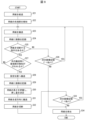
図3は、図1及び図2に示す印刷装置1が備える制御部100による制御の流れを示すフローチャートである。図4は、図1及び図2に示す印刷装置1において、用紙Pの搬送の様子を示す図である。図5は、図1及び図2に示す印刷装置1において、用紙Pの切断等の様子を示す図である。
[Control flow by the control unit]
Fig. 3 is a flowchart showing a flow of control by the
なお、図3に示すフローチャートは一例であり、これに限定されない。また、図4及び図5においては、図1に示す部材のうち一部の部材については省略している。図3に示すフローチャートにおいて、印刷装置1の電源がオンされ、制御部100が、USBインターフェース110またはLANインターフェース111を介して、印刷ジョブを受信した場合を考える。
Note that the flowchart shown in FIG. 3 is an example, and is not limiting. Also, some of the components shown in FIG. 1 are omitted in FIGS. 4 and 5. In the flowchart shown in FIG. 3, consider a case where the
この場合、ステップS1において、制御部100は、給送モータ107を用いて給送ローラ23を回転させることにより、給送トレイ21に収容されている用紙Pを搬送路R1に給送する。給送ローラ23により用紙Pが給送され、用紙Pの先端部FEがレジセンサ120の位置に到達すると、ステップS2において、制御部100は、レジセンサ120により用紙Pの先端部FEを検知する。
In this case, in step S1, the
制御部100がレジセンサ120により用紙Pの先端部FEを検知すると、ステップS3において、制御部100は、搬送ローラ60により用紙Pを画像記録部3の位置へ搬送する。次に、ステップS4において、制御部100は、画像記録部3により用紙Pへ1行分の画像を記録する。
When the
制御部100が画像記録部3により用紙Pへ1行分の画像を記録した後、ステップS5において、制御部100は、用紙Pを切断する指示はあるか否かを判定する。ステップS5にてNOの場合、つまり、制御部100が、用紙Pを切断する指示がないと判定した場合、ステップS6において、制御部100は、次の画像記録データがあるか否かを判定する。当該次の画像記録データは、印刷ジョブにおいて用紙Pに画像が記録される範囲として設定された画像記録範囲のうち、ステップS4で用紙Pに記録された1行の画像の次の行の画像のデータである。
After the
ステップS6にてYESの場合、つまり、制御部100が、次の画像記録データがあると判定した場合、ステップS3に戻り、制御部100は、搬送部6により用紙Pを上述した所定搬送量だけ搬送する。制御部100が用紙Pを当該所定搬送量だけ搬送した後、ステップS4以降に続く。ステップS6にてNOの場合、つまり、制御部100が、次の画像記録データがないと判定した場合、ステップS12に移る。
If step S6 is YES, that is, if the
ステップS5にてYESの場合、つまり、制御部100が、用紙Pを切断する指示があると判定した場合、ステップS7において、制御部100は、レジセンサ120により用紙Pの後端部BEを検知したか否かを判定する。ステップS7にてNOの場合、つまり、制御部100がレジセンサ120により用紙Pの後端部BEを検知していない場合、ステップS3に戻り、制御部100は、搬送部6により用紙Pを上記所定搬送量だけ搬送する。
If the answer is YES in step S5, that is, if the
制御部100は、ステップS3~S7の処理を繰り返すことにより、画像記録部3により用紙Pに1行分の画像を記録する処理と、搬送部6により用紙Pを上記所定搬送量だけ搬送する処理と、を含む処理として画像記録処理を実行する。
By repeating steps S3 to S7, the
ステップS7にてYESの場合、つまり、図4の(A)に示すように、制御部100がレジセンサ120により用紙Pの後端部BEを検知した場合、ステップS8において、制御部100は、用紙Pの長さLpを把握し、用紙Pの戻し量Lbを決定する。用紙Pの戻し量Lbについては図4の(B)に示す。
If the answer is YES in step S7, that is, if the
このとき、制御部100は、レジセンサ120により用紙Pの後端部BEを検知することで用紙Pの長さLpを把握する。具体的には、制御部100は、レジセンサ120が用紙Pの先端部FEを検知してからレジセンサ120が用紙Pの後端部BEを検知するまでの間に、ロータリエンコーダ121が検知した用紙Pの搬送量に基づいて用紙Pにおける搬送方向D1の長さLpを把握する。
At this time, the
なお、メディアセンサ122が用紙Pの先端部FE及び後端部BEの両方を検知する場合を考える。この場合、制御部100は、メディアセンサ122が用紙Pの先端部FEを検知してからメディアセンサ122が用紙Pの後端部BEを検知するまでの間に、ロータリエンコーダ121が検知した用紙Pの搬送量に基づいて用紙Pの長さLpを把握する。
Let us consider a case where the
また、制御部100は、把握した用紙Pの長さLpに基づき用紙Pの切断位置CLを算出する算出処理を実行する。切断位置CLについては図5の(A)に示す。例えば、切断部7により用紙Pが2等分に切断される場合、制御部100は、Lp=297mmを2等分に切断したLp/2=148.5mmを算出する。制御部100は、用紙Pの先端部FEまたは後端部BEからLp/2にある位置を用紙Pの切断位置CLとして算出する。なお、制御部100による用紙Pの戻し量Lbの決定方法については後述する。
The
上述のとおり、制御部100は、レジセンサ120により用紙Pの後端部BEを検知することで用紙Pの長さLpを把握し、用紙Pの長さLpに基づき用紙Pの切断位置CLを算出する。これにより、用紙Pのサイズが変更された場合であっても、用紙Pの切断位置CLにバラつきが生じることを防ぐことができる。なお、A4サイズの用紙が2等分に切断される場合、レジセンサ120の位置と切断部7の位置との間の距離Lsは長さLp/2よりも短い。また、レターサイズの用紙が2等分に切断される場合、距離Lsは長さLp/2よりも長い。
As described above, the
制御部100が用紙Pの戻し量Lbを決定した後、制御部100は、画像記録部3による上記画像記録処理を中断する中断処理を実行する。そして、ステップS9において、図4の(B)に示すように、制御部100は、搬送部6により用紙Pを戻し量Lbだけ搬送方向D1とは逆方向D2に搬送する搬送処理を実行する。制御部100は、搬送部6により用紙Pを戻し量Lbだけ逆方向D2に搬送することで、用紙Pの切断位置CLを切断部7の位置へ移動させる。
After the
制御部100が搬送部6により用紙Pを戻し量Lbだけ逆方向D2に搬送した後、ステップS10において、図5の(A)に示すように、制御部100は、切断部7により用紙Pを切断位置CLで切断する上述の切断処理を実行する。例えば、切断部7により用紙Pが2等分に切断される場合、用紙Pが第1用紙P1及び第2用紙P2に切断される。また、用紙PがA4サイズである場合、A5サイズの第1用紙P1及び第2用紙P2が生成される。なお、図5の(B)に示すように、搬送路R1において、第2用紙P2が第1用紙P1よりも先行して搬送される。
After the
ステップS8~S10のように、用紙Pの長さLpを把握した後に、用紙Pを搬送方向D1とは逆方向D2に搬送して、用紙Pを切断する切断処理を実行する。このため、用紙Pを搬送方向D1とは逆方向D2に搬送せずに、用紙Pを切断する切断処理を実行する場合に比べて、切断部7の位置と、レジセンサ120による用紙Pの後端部BEの検知位置と、の間の距離を小さくすることができる。これにより、印刷装置1のサイズを小さくすることができる。
After determining the length Lp of the paper P as in steps S8 to S10, the paper P is transported in the direction D2 opposite the transport direction D1, and a cutting process is performed to cut the paper P. Therefore, compared to a case where the paper P is not transported in the direction D2 opposite the transport direction D1 and a cutting process is performed to cut the paper P, the distance between the position of the
また、仮に、搬送ローラ66付近において搬送路R1から分離し、搬送開始位置Vで搬送路R1に合流する両面搬送経路が設けられる構成を考える。この構成において、当該両面搬送経路に用紙Pを通し、用紙Pの長さを把握した後に用紙Pに画像を記録する場合に比べて、画像の記録にかかる時間を短縮することができる。
Also, consider a configuration in which a double-sided transport path is provided that separates from transport path R1 near
制御部100が切断部7により用紙Pを切断した後、制御部100は、ステップS11の処理に先立って、用紙Pの残り搬送量Lfを決定する。制御部100による用紙Pの残り搬送量Lfの決定方法については後述する。制御部100は、用紙Pの残り搬送量Lfを決定した後、搬送部6により用紙Pを残り搬送量Lfだけ搬送方向D1に搬送する。これにより、用紙Pの位置が逆方向D2に搬送される前の位置に戻る。
After the
制御部100が搬送部6により用紙Pを残り搬送量Lfだけ搬送方向D1に搬送した後、ステップS11において、制御部100は、次の画像記録データがあるか否かを判定する。ステップS11の処理は、ステップS6の処理と同様である。
After the
ステップS11にてYESの場合、つまり、制御部100が、次の画像記録データがあると判定した場合、ステップS3に戻り、ステップS4が再度実行される。即ち、制御部100は、ステップS10の上記切断処理の後、画像記録部3により、上記切断処理にて切断された用紙Pに対して、ステップS9に先立って実行された上記中断処理にて中断されたステップS3~S7の上記画像記録処理を再開する再開処理を実行する。制御部100は、当該再開処理にて、用紙Pの上述した画像記録範囲のうち残りの部分に画像を記録する。
If step S11 is YES, that is, if the
これにより、用紙Pを搬送方向D1とは逆方向D2に搬送して、用紙Pを切断する切断処理を実行する場合においても、用紙Pの上記画像記録範囲の全てに画像を記録することができる。よって、印刷装置1のサイズを小さくすることと、用紙Pの上記画像記録範囲の全てに画像を記録することと、を両立することができる。
As a result, even when the paper P is transported in the direction D2 opposite to the transport direction D1 and a cutting process is performed to cut the paper P, an image can be recorded in the entire image recording range of the paper P. This makes it possible to both reduce the size of the
ステップS11にてNOの場合、つまり、制御部100が、次の画像記録データがないと判定した場合、ステップS12において、制御部100は、搬送部6により第1用紙P1を排出トレイ22に排出する。
If the answer is NO in step S11, that is, if the
[用紙の戻し量の決定方法]
図6は、図1及び図2に示す印刷装置1が備える制御部100による用紙Pの戻し量Lbの決定方法を説明するための図である。図6において、説明の便宜上、用紙Pを2枚重ねて記載している。また、図6においては、図1に示す部材のうち一部の部材については省略している。上の用紙Pは、逆方向D2に搬送された後の用紙Pを示しており、下の用紙Pは、逆方向D2に搬送される前の用紙Pを示している。制御部100は、用紙Pの長さLpと、レジセンサ120が用紙Pの先端FEを検知してからの用紙Pの累積搬送量Ltと、レジセンサ120の位置と切断部7の位置との間の距離Lsと、に基づき用紙Pの戻し量Lbを決定する。
[How to determine the paper return amount]
6 is a diagram for explaining a method of determining the return amount Lb of the paper P by the
具体的には、制御部100は、レジセンサ120が用紙Pの先端FEを検知してからロータリエンコーダ121が検知した用紙Pの搬送量を累積搬送量Ltとして把握する。また、制御部100は、ROM102またはEEPROM104に格納された情報から距離Lsを把握する。制御部100は、以下の式(1)により用紙Pの戻し量Lbを決定する。戻し量Lbは、逆方向D2に搬送される前の用紙Pの先端部FEと切断部7の位置との間の距離Lt-Lsと、用紙Pの長さの半分Lp/2と、の差分である。
Specifically, the
Lb=Lt-Ls-Lp/2・・・(1)
[用紙の残り搬送量の決定方法]
図7は、図1及び図2に示す印刷装置1が備える制御部100による用紙Pの残り搬送量Lfの決定方法を説明するための図である。図7において、説明の便宜上、用紙Pを2枚重ねて記載している。また、図7においては、図1に示す部材のうち一部の部材については省略している。上の用紙Pは、搬送方向D1に搬送された後の用紙Pを示しており、下の用紙Pは、搬送方向D1に搬送される前の用紙Pを示している。制御部100は、以下の式(2)により用紙Pの残り搬送量Lfを決定する。残り搬送量Lfは、戻し量Lbの正負を逆にした値である。
Lb=Lt-Ls-Lp/2...(1)
[Method of determining remaining paper transport amount]
7 is a diagram for explaining a method for determining the remaining transport amount Lf of the paper P by the
Lf=Ls+Lp/2-Lt・・・(2)
[変形例1]
上述において印刷装置1については、切断部7により用紙Pを切断することで、用紙Pを複数に分割するものとしたが、これに限られない。印刷装置1は切断部7の代わりに、分割部の一例として、用紙Pに対してミシン目形成加工を実行する加工部を備えてもよい。この場合、制御部100は、加工部により用紙Pに対して、用紙Pの分割位置の一例である加工位置でミシン目形成加工を実行する加工処理を行う。当該加工位置は、切断位置CLと同じ位置である。
Lf=Ls+Lp/2-Lt...(2)
[Modification 1]
In the above description, the
具体的には、加工部は、円盤の円周上に等間隔に刃が形成されたミシン目カッターと、上述したカッターキャリッジと、を有する。加工部は、カッターキャリッジを用紙Pの幅方向に移動させ、ミシン目カッターにより用紙Pの加工位置に沿って間隔をあけて複数の切れ込みを形成することで、用紙Pにミシン目を形成する。 Specifically, the processing unit has a perforation cutter with blades formed at equal intervals on the circumference of a disk, and the cutter carriage described above. The processing unit forms perforations in the paper P by moving the cutter carriage in the width direction of the paper P and using the perforation cutter to form multiple cuts at intervals along the processing position of the paper P.
[変形例2]
図8は、図1及び図2に示す印刷装置1が備える切断部7の変形例である加工部7A,7Bの構成を示す図である。印刷装置1は切断部7の代わりに、分割部の一例として、図8の(A)に示すように、用紙Pに対して折り目形成加工を実行する加工部7Aを備えてもよい。この場合、制御部100は、加工部7Aにより用紙Pに対して、用紙Pの加工位置CL1で折り目形成加工を実行する加工処理を行う。
[Modification 2]
Fig. 8 is a diagram showing the configuration of
加工部7Aは、カッターキャリッジ71と、ブレード72と、挟持部材73と、を有する。ブレード72は丸刃であり、カッターキャリッジ71に設けられている。ブレード72は、用紙Pに当接しても用紙Pを切断しない程度に形成されたものである。挟持部材73には凹部74が形成されており、凹部74は、ブレード72と対向する位置に配置される。加工部7Aは、カッターキャリッジ71を用紙Pの幅方向に移動させることで、ブレード72により用紙Pを凹部74に押し付ける。これにより、用紙Pの加工位置CL1に沿って折り目が形成される。
The
また、印刷装置1は切断部7の代わりに、分割部の一例として、図8の(B)に示す加工部7Bを備えてもよい。加工部7Bは、挟持部材73と、押し出し部材75と、を有する。押し出し部材75は、用紙Pを加工位置CL1でZの負の方向に押し出すためのものであり、例えば、Y方向に延伸するとともに用紙Pに当接しても用紙Pを切断しない程度に形成された長方形状のブレードである。挟持部材73に形成された凹部74は、押し出し部材75と対向する位置に配置される。
In addition, the
加工部7Bは、押し出し部材75をZの負の方向に移動させることにより、用紙Pの加工位置CL1に沿って押し出し部材75を当接させて用紙Pを加工位置CL1でZの負の方向に押し出す。また、加工部7Bは、押し出し部材75によって押し出された用紙Pを挟持部材73の凹部74によって挟持することにより、用紙Pの加工位置CL1に折り目を形成する。
The
[変形例3]
制御部100は、ステップS7とS8との間に、以下の処理を実行してもよい。具体的には、制御部100は、画像記録部3により用紙Pに記録される画像に基づき、ステップS3~S7の上記画像記録処理を中断するか否かを決定する決定処理を実行してもよい。制御部100が当該決定処理にて上記画像記録処理を中断すると決定した場合、ステップS8に移る。
[Modification 3]
The
制御部100が上記決定処理にて上記画像記録処理を中断しないと決定した場合、制御部100は、ステップS11の処理をステップS8の処理に先立って実行し、ステップS10の後にはステップS11の処理を実行しない。この構成では、ステップS11にてNOの場合にステップS8に移り、ステップS8において、制御部100は、以下の式(3)により用紙Pの戻し量Lbを決定する。
If the
Lb=Lt-Ls・・・(3)
これにより、上記画像記録処理が中断されることなく、用紙Pに画像が全て記録された後に、ステップS9にて搬送部6により用紙Pが逆方向D2に搬送されて、ステップS10にて切断部7により用紙Pが切断される。
Lb=Lt-Ls...(3)
As a result, the image recording process is not interrupted, and after all images are recorded on the paper P, the paper P is conveyed in the reverse direction D2 by the conveying
以上の通り、上記画像記録処理を中断して上述した搬送処理及び切断処理を実行する場合、用紙Pに画像が全て記録される前に当該搬送処理及び切断処理を実行するため、搬送方向D1とは逆方向D2への搬送量が抑えられ、処理時間を短縮することができる。一方、上記画像記録処理を中断せずに上記搬送処理及び切断処理を実行する場合、用紙Pに記録される画像が途切れることを防ぐことができ、用紙Pに画像を鮮明に記録することができる。制御部100が上記画像記録処理を中断するか否かを決定する決定処理を実行することにより、画像に応じて処理時間の短縮または画像の鮮明さのうちいずれを優先させるかを決定することができる。
As described above, when the image recording process is interrupted to perform the above-mentioned conveying process and cutting process, the conveying process and cutting process are performed before the entire image is recorded on the paper P, so the amount of conveying in the direction D2 opposite to the conveying direction D1 is reduced, and the processing time can be shortened. On the other hand, when the conveying process and cutting process are performed without interrupting the image recording process, it is possible to prevent the image recorded on the paper P from being interrupted, and the image can be clearly recorded on the paper P. The
また、上記決定処理について、例えば制御部100は、印刷ジョブに含まれる画像のデータから用紙Pに記録される画像を把握し、用紙Pの切断位置CLに対応する部分の画像の1行が空白であるか否かを判定してもよい。制御部100は、用紙Pの切断位置CLに対応する部分の画像の1行が空白であると判定した場合、上記決定処理にて上記画像記録処理を中断することに決定する。制御部100は、用紙Pの切断位置CLに対応する部分の画像の1行が空白ではないと判定した場合、上記決定処理にて上記画像記録処理を中断しないことに決定する。
In addition, in the above-mentioned determination process, for example, the
用紙Pの切断位置CLに対応する部分の画像の1行が空白である場合、上記画像記録処理を中断したとしても、用紙Pに記録される画像の鮮明さには影響しない。逆に、用紙Pの切断位置CLに対応する部分の画像の1行が空白ではない場合、上記画像記録処理を中断しないことによって、用紙Pに記録される画像の鮮明さを優先させることができる。 If one line of the image in the portion of the paper P that corresponds to the cutting position CL is blank, interrupting the image recording process does not affect the clarity of the image recorded on the paper P. Conversely, if one line of the image in the portion of the paper P that corresponds to the cutting position CL is not blank, the clarity of the image recorded on the paper P can be prioritized by not interrupting the image recording process.
さらに、上記決定処理について、例えば制御部100は、ユーザにより設定部123でなされた設定に応じて、上記画像記録処理を中断するか否かを決定してもよい。この場合、ユーザは設定部123により上記画像記録処理を中断するか否かを選択することができる。設定部123において上記画像記録処理の中断が選択された場合、制御部100は、上記決定処理にて上記画像記録処理を中断することに決定する。設定部123において上記画像記録処理の中断が設定されていない場合、制御部100は、上記決定処理にて上記画像記録処理を中断しないことに決定する。
Furthermore, in the above-mentioned decision process, for example, the
また、上記決定処理について、例えば制御部100は、用紙Pの種別に基づき、上記画像記録処理を中断するか否かを決定してもよい。用紙Pの種別が普通紙である場合、制御部100は、上記決定処理にて上記画像記録処理を中断することに決定し、用紙Pの種別が光沢紙である場合、制御部100は、上記決定処理にて上記画像記録処理を中断しないことに決定する。
In addition, in the above-mentioned determination process, for example, the
〔実施形態2〕
本発明の実施形態2について、以下に説明する。なお、説明の便宜上、実施形態1にて説明した部材と同じ機能を有する部材については、同じ符号を付記し、その説明を繰り返さない。図9は、本発明の実施形態2に係る印刷装置1が備える制御部100による制御の流れを示すフローチャートである。
[Embodiment 2]
A second embodiment of the present invention will be described below. For ease of explanation, the same reference numerals are used for members having the same functions as those described in the first embodiment, and the description thereof will not be repeated. Fig. 9 is a flowchart showing the flow of control by the
図9に示すフローチャートにおいて、ステップS21~S26の処理はそれぞれ、図3に示すステップS1~S6の処理と同様である。ステップS25にてYESの場合、つまり、制御部100が、用紙Pを切断する指示があると判定した場合を考える。
In the flowchart shown in FIG. 9, the processes in steps S21 to S26 are the same as the processes in steps S1 to S6 shown in FIG. 3. Consider the case where the answer is YES in step S25, that is, where the
この場合、ステップS27において、制御部100は、用紙Pの上述した所定搬送量の搬送が行われる場合にレジセンサ120により用紙Pの後端部BEの検知が行われるか否かを判定する。具体的には、制御部100は、上述した累積搬送量Ltについて、現在の累積搬送量Ltに上記所定搬送量を加えた値が所定閾値以上となるか否かを判定する。当該所定閾値は、印刷ジョブで設定された用紙Pの長さである。
In this case, in step S27, the
ステップS27にてNOの場合、つまり、制御部100が用紙Pの後端部BEの検知が行われないと判定した場合、ステップS23に戻る。このとき、ステップS23において、制御部100は、搬送部6により用紙Pを上記所定搬送量だけ搬送する。
If the answer is NO in step S27, that is, if the
ステップS27にてYESの場合、つまり、制御部100が用紙Pの後端部BEの検知が行われると判定した場合を考える。この場合、ステップS28において、制御部100は、設定位置に用紙Pを搬送する。当該設定位置は、累積搬送量Ltが上記所定閾値に達した場合の用紙Pの位置である。このとき、レジセンサ120が用紙Pの後端部BEを検知し、制御部100は、レジセンサ120により用紙Pの後端部BEを検知したと判定する。そして、制御部100は、搬送部6による用紙Pの搬送を停止する停止処理を実行する。
Consider the case where step S27 is YES, that is, where the
換言すると、制御部100は、搬送部6による搬送方向D1への用紙Pの搬送量として累積搬送量Ltが上記所定閾値に達すると、搬送部6による用紙Pの搬送を停止する停止処理を実行する。また、上記所定閾値は、搬送ローラ60及びピンチローラ61によって用紙Pが挟持される状態が維持される累積搬送量Ltの上限値である。これにより、搬送ローラ60及びピンチローラ61によって用紙Pが挟持される状態を維持することができるため、用紙Pの搬送精度を向上するとともに、ジャムの発生を防止することができる。
In other words, when the cumulative transport amount Lt, which is the amount of transport of the paper P in the transport direction D1 by the
制御部100は、上記設定位置に用紙Pを搬送しながら、ステップS29において、画像記録部3により用紙Pに画像を記録する。ステップS29の処理は、図3に示すステップS3~S7の上記画像記録処理と同様である。なお、ステップS30~S34の処理はそれぞれ、図3に示すステップS8~S12の処理と同様である。
While conveying the paper P to the set position, the
〔実施形態3〕
本発明の実施形態3について、以下に説明する。なお、説明の便宜上、実施形態1及び2にて説明した部材と同じ機能を有する部材については、同じ符号を付記し、その説明を繰り返さない。図10は、本発明の実施形態3に係る印刷装置1が備える制御部100による制御を説明するための図である。図11は、図10に示す印刷装置1が搬送する用紙Pを示す図である。また、図10においては、図1に示す部材のうち一部の部材については省略している。
[Embodiment 3]
A third embodiment of the present invention will be described below. For ease of explanation, the same reference numerals are given to components having the same functions as those described in the first and second embodiments, and the explanations thereof will not be repeated. Fig. 10 is a diagram for explaining the control by the
実施形態3では、図9に示すフローチャートのステップS29において、制御部100は、画像記録部3により用紙Pの第1領域A1に画像を記録する第1画像記録処理を実行する。用紙Pの第1領域A1については図11に示す。当該第1画像記録処理は、図3に示すステップS3~S7の上記画像記録処理と同様の方法で、用紙Pの第1領域A1に画像を記録する処理である。
In the third embodiment, in step S29 of the flowchart shown in FIG. 9, the
また、図9に示すステップS32の切断処理の後、ステップS33にてYESの場合、つまり、制御部100が次の画像記録データがあると判定した場合を考える。この場合、ステップS23~S27において、制御部100は、画像記録部3により用紙Pのうち第1領域A1以外の領域に含まれる第2領域A2に画像を記録する第2画像記録処理を実行する。当該第2画像記録処理は、図3に示すステップS3~S7の上記画像記録処理と同様の方法で、用紙Pの第2領域A2に画像を記録する処理である。
Furthermore, consider the case where, after the cutting process in step S32 shown in FIG. 9, the answer is YES in step S33, that is, the
第1領域A1及び第2領域A2は、実施形態1にて記載した用紙Pの画像記録範囲を構成する。第1領域A1は、制御部100によりステップS30の上述した搬送処理が実行される場合に、挟持領域A3以外の領域に含まれる。挟持領域A3は、用紙Pのうち搬送ローラ60及びピンチローラ61によって挟持される領域である。
The first area A1 and the second area A2 constitute the image recording range of the paper P described in the first embodiment. The first area A1 is included in the area other than the clamping area A3 when the
第1領域A1が用紙Pのうち挟持領域A3以外の領域に含まれることにより、搬送ローラ60及びピンチローラ61が第1領域A1を挟持することを防ぐことができ、搬送ローラ60及びピンチローラ61が汚れることを防ぐことができる。
By including the first area A1 in an area of the paper P other than the clamping area A3, the conveying
また、第1領域A1は、ステップS30において決定された戻し量Lbが事前に推定した最大値となった場合においても、挟持領域A3以外の領域に含まれる。図6において、画像記録部3におけるXの負の方向側の端部と、搬送ローラ60の回転軸の位置と、の間の距離をL1とする。この場合、第1領域A1は、L1>Lbの条件を満たす領域となる。
The first area A1 is included in the area other than the clamping area A3 even if the return amount Lb determined in step S30 becomes the maximum value estimated in advance. In FIG. 6, the distance between the end of the
本発明は上述した各実施形態に限定されるものではなく、請求項に示した範囲で種々の変更が可能であり、異なる実施形態にそれぞれ開示された技術的手段を適宜組み合わせて得られる実施形態についても本発明の技術的範囲に含まれる。 The present invention is not limited to the above-described embodiments, and various modifications are possible within the scope of the claims. The technical scope of the present invention also includes embodiments obtained by appropriately combining the technical means disclosed in different embodiments.
1 印刷装置
3 画像記録部
6 搬送部
7 切断部
100 制御部
120 レジセンサ(検知部)
122 メディアセンサ(検知部)
A1 用紙の第1領域
A2 用紙の第2領域
A3 挟持領域
CL 切断位置
D1 搬送方向
D2 逆方向
BE 用紙の後端部
REFERENCE SIGNS
122 Media sensor (detection unit)
A1: First area of the sheet A2: Second area of the sheet A3: Clamping area CL: Cutting position D1: Conveying direction D2: Reverse direction BE: Rear end of the sheet
Claims (8)
前記搬送部により搬送方向に搬送される前記印刷媒体に画像を記録する画像記録部と、
前記画像記録部により画像が記録されて、前記搬送部により搬送される前記印刷媒体を分割するものであり、前記画像記録部よりも前記搬送方向の下流に設けられる分割部と、
前記分割部よりも前記搬送方向の上流に設けられ、前記印刷媒体の後端部を検知する検知部と、
制御部と、
を備え、
前記制御部は、
前記検知部により前記後端部を検知することで前記印刷媒体の長さを把握し、前記印刷媒体の長さに基づき前記印刷媒体の分割位置を算出する算出処理と、
前記算出処理の後、前記搬送部により前記印刷媒体を前記搬送方向とは逆方向に搬送することで、前記分割位置を前記分割部の位置へ移動させる搬送処理と、
前記搬送処理の後、前記分割部により前記印刷媒体を前記分割位置で分割する分割処理と、
を含む処理を実行することを特徴とする印刷装置。 A transport unit that transports the print medium;
an image recording unit that records an image on the print medium that is transported in a transport direction by the transport unit;
a dividing section that divides the print medium on which an image is recorded by the image recording section and that is transported by the transport section, the dividing section being disposed downstream of the image recording section in the transport direction;
a detection unit that is provided upstream of the dividing unit in the transport direction and detects a rear end of the print medium;
A control unit;
Equipped with
The control unit is
a calculation process of detecting the rear end portion of the print medium by the detection unit, grasping the length of the print medium, and calculating a division position of the print medium based on the length of the print medium;
a conveying process in which, after the calculation process, the conveying unit conveys the print medium in a direction opposite to the conveying direction, thereby moving the division position to a position of the dividing unit;
a dividing process in which the dividing unit divides the print medium at the dividing position after the conveying process;
A printing device that executes a process including the steps of:
前記制御部は、前記検知部により前記後端部を検知した場合、前記搬送部による前記搬送方向への前記印刷媒体の搬送量が所定閾値に達すると、前記搬送部による前記印刷媒体の搬送を停止する停止処理を実行し、前記停止処理の後に前記搬送処理を実行し、
前記所定閾値は、前記搬送ローラ対によって前記印刷媒体が挟持される状態が維持される前記搬送量の上限値であることを特徴とする請求項1に記載の印刷装置。 the transport unit is provided upstream of the image recording unit in the transport direction, and includes a pair of transport rollers that transport the print medium;
when the detection unit detects the rear end, and when a transport amount of the print medium in the transport direction by the transport unit reaches a predetermined threshold, the control unit executes a stop process to stop transport of the print medium by the transport unit, and executes the transport process after the stop process;
2 . The printing apparatus according to claim 1 , wherein the predetermined threshold value is an upper limit of the transport amount at which the print medium is maintained in a state where it is sandwiched between the pair of transport rollers.
前記画像記録部により前記印刷媒体の第1領域に画像を記録する第1画像記録処理と、
前記分割処理の後、前記画像記録部により前記印刷媒体のうち前記第1領域以外の領域に含まれる第2領域に画像を記録する第2画像記録処理と、
を含む処理を実行し、
前記第1領域は、前記制御部により前記搬送処理が実行される場合に、前記印刷媒体のうち前記搬送ローラ対によって挟持される挟持領域以外の領域に含まれることを特徴とする請求項2に記載の印刷装置。 The control unit is
a first image recording process for recording an image in a first area of the print medium by the image recording unit;
a second image recording process in which, after the division process, the image recording unit records an image in a second area of the print medium that is included in an area other than the first area;
Perform a process including
The printing device according to claim 2 , wherein the first area is included in an area of the printing medium other than a clamped area that is clamped by the pair of conveying rollers when the conveying process is executed by the control unit.
前記搬送処理及び前記分割処理に先立って実行される、前記画像記録部により前記印刷媒体に画像を記録する画像記録処理と、
前記搬送処理及び前記分割処理に先立って実行される、前記画像記録処理を中断する中断処理と、
前記分割処理の後、前記画像記録部により、前記分割処理にて分割された前記印刷媒体に対して、前記中断処理にて中断された前記画像記録処理を再開することにより、前記印刷媒体の画像記録範囲のうち残りの部分に画像を記録する再開処理と、
を含む処理を実行することを特徴とする請求項1に記載の印刷装置。 The control unit is
an image recording process of recording an image on the print medium by the image recording unit, the image recording process being executed prior to the transport process and the division process;
an interruption process of interrupting the image recording process, the interruption process being executed prior to the conveying process and the dividing process;
a restart process in which, after the division process, the image recording unit restarts the image recording process interrupted in the interruption process on the print medium divided in the division process, thereby recording an image on a remaining portion of an image recording range of the print medium;
The printing apparatus according to claim 1 , wherein the printing apparatus executes a process including:
前記搬送部により搬送方向に搬送される前記印刷媒体に画像を記録する画像記録部と、
前記画像記録部により画像が記録されて、前記搬送部により搬送される前記印刷媒体に対して、(i)切断加工、(ii)ミシン目形成加工及び(iii)折り目形成加工のうちの1つを実行するものであり、前記画像記録部よりも前記搬送方向の下流に設けられる加工部と、
前記加工部よりも前記搬送方向の上流に設けられ、前記印刷媒体の後端部を検知する検知部と、
制御部と、
を備え、
前記制御部は、
前記検知部により前記後端部を検知することで前記印刷媒体の長さを把握し、前記印刷媒体の長さに基づき前記印刷媒体の加工位置を算出する算出処理と、
前記算出処理の後、前記搬送部により前記印刷媒体を前記搬送方向とは逆方向に搬送することで、前記加工位置を前記加工部の位置へ移動させる搬送処理と、
前記搬送処理の後、前記加工部により前記印刷媒体に対して、前記加工位置で前記(i)、(ii)及び(iii)のうちの1つを実行する加工処理と、
を含む処理を実行することを特徴とする印刷装置。 A transport unit that transports the print medium;
an image recording unit that records an image on the print medium that is transported in a transport direction by the transport unit;
a processing unit that performs one of (i) cutting, (ii) perforation, and (iii) fold formation on the print medium on which an image is recorded by the image recording unit and which is transported by the transport unit, the processing unit being disposed downstream of the image recording unit in the transport direction;
a detection unit that is provided upstream of the processing unit in the transport direction and detects a rear end of the print medium;
A control unit;
Equipped with
The control unit is
a calculation process of detecting the rear end portion of the print medium by the detection unit to grasp the length of the print medium and calculating a processing position of the print medium based on the length of the print medium;
a conveying process in which, after the calculation process, the conveying unit conveys the print medium in a direction opposite to the conveying direction, thereby moving the processing position to a position of the processing unit;
After the transport process, the processing unit performs one of (i), (ii), and (iii) on the print medium at the processing position; and
A printing device that executes a process including the steps of:
前記搬送部により搬送方向に搬送される前記印刷媒体に画像を記録する画像記録部と、
前記画像記録部により画像が記録されて、前記搬送部により搬送される前記印刷媒体を分割するものであり、前記画像記録部よりも前記搬送方向の下流に設けられる分割部と、
前記分割部よりも前記搬送方向の上流に設けられ、前記印刷媒体の後端部を検知する検知部と、
制御部と、
を備える印刷装置の制御方法であって、
前記検知部により前記後端部を検知することで前記印刷媒体の長さを把握し、前記印刷媒体の長さに基づき前記印刷媒体の分割位置を算出する算出ステップと、
前記算出ステップの後、前記搬送部により前記印刷媒体を前記搬送方向とは逆方向に搬送することで、前記分割位置を前記分割部の位置へ移動させる搬送ステップと、
前記搬送ステップの後、前記分割部により前記印刷媒体を前記分割位置で分割する分割ステップと、
を含むことを特徴とする印刷装置の制御方法。 A transport unit that transports the print medium;
an image recording unit that records an image on the print medium that is transported in a transport direction by the transport unit;
a dividing section that divides the print medium on which an image is recorded by the image recording section and that is transported by the transport section, the dividing section being disposed downstream of the image recording section in the transport direction;
a detection unit that is provided upstream of the dividing unit in the transport direction and detects a rear end of the print medium;
A control unit;
A method for controlling a printing device comprising:
a calculation step of detecting the rear end portion of the print medium by the detection unit to grasp the length of the print medium and calculating a division position of the print medium based on the length of the print medium;
a conveying step of conveying the print medium in a direction opposite to the conveying direction by the conveying unit after the calculation step, thereby moving the division position to a position of the dividing unit;
a dividing step of dividing the print medium at the dividing position by the dividing unit after the conveying step;
13. A method for controlling a printing device, comprising:
前記搬送部により搬送方向に搬送される前記印刷媒体に画像を記録する画像記録部と、
前記画像記録部により画像が記録されて、前記搬送部により搬送される前記印刷媒体に対して、(i)切断加工、(ii)ミシン目形成加工及び(iii)折り目形成加工のうちの1つを実行するものであり、前記画像記録部よりも前記搬送方向の下流に設けられる加工部と、
前記加工部よりも前記搬送方向の上流に設けられ、前記印刷媒体の後端部を検知する検知部と、
制御部と、
を備える印刷装置の制御方法であって、
前記検知部により前記後端部を検知することで前記印刷媒体の長さを把握し、前記印刷媒体の長さに基づき前記印刷媒体の加工位置を算出する算出ステップと、
前記算出ステップの後、前記搬送部により前記印刷媒体を前記搬送方向とは逆方向に搬送することで、前記加工位置を前記加工部の位置へ移動させる搬送ステップと、
前記搬送ステップの後、前記加工部により前記印刷媒体に対して、前記加工位置で前記(i)、(ii)及び(iii)のうちの1つを実行する加工ステップと、
を含むことを特徴とする印刷装置の制御方法。 A transport unit that transports the print medium;
an image recording unit that records an image on the print medium that is transported in a transport direction by the transport unit;
a processing unit that performs one of (i) cutting, (ii) perforation, and (iii) fold formation on the print medium on which an image is recorded by the image recording unit and which is transported by the transport unit, the processing unit being disposed downstream of the image recording unit in the transport direction;
a detection unit that is provided upstream of the processing unit in the transport direction and detects a rear end of the print medium;
A control unit;
A method for controlling a printing device comprising:
a calculation step of detecting the rear end portion of the print medium by the detection unit to grasp the length of the print medium and calculating a processing position of the print medium based on the length of the print medium;
a conveying step of conveying the print medium in a direction opposite to the conveying direction by the conveying unit after the calculation step, thereby moving the processing position to a position of the processing unit;
a processing step in which, after the conveying step, the processing unit performs one of (i), (ii), and (iii) on the print medium at the processing position;
13. A method for controlling a printing device, comprising:
Priority Applications (3)
| Application Number | Priority Date | Filing Date | Title |
|---|---|---|---|
| JP2021013967A JP7581925B2 (en) | 2021-01-29 | 2021-01-29 | Printing device and method for controlling printing device |
| US17/587,076 US11838463B2 (en) | 2021-01-29 | 2022-01-28 | Printing apparatus and method for controlling printing apparatus |
| CN202210110742.4A CN114803585B (en) | 2021-01-29 | 2022-01-29 | Printing device and printing device control method |
Applications Claiming Priority (1)
| Application Number | Priority Date | Filing Date | Title |
|---|---|---|---|
| JP2021013967A JP7581925B2 (en) | 2021-01-29 | 2021-01-29 | Printing device and method for controlling printing device |
Publications (2)
| Publication Number | Publication Date |
|---|---|
| JP2022117340A JP2022117340A (en) | 2022-08-10 |
| JP7581925B2 true JP7581925B2 (en) | 2024-11-13 |
Family
ID=82527703
Family Applications (1)
| Application Number | Title | Priority Date | Filing Date |
|---|---|---|---|
| JP2021013967A Active JP7581925B2 (en) | 2021-01-29 | 2021-01-29 | Printing device and method for controlling printing device |
Country Status (3)
| Country | Link |
|---|---|
| US (1) | US11838463B2 (en) |
| JP (1) | JP7581925B2 (en) |
| CN (1) | CN114803585B (en) |
Families Citing this family (2)
| Publication number | Priority date | Publication date | Assignee | Title |
|---|---|---|---|---|
| JP7456346B2 (en) * | 2020-09-30 | 2024-03-27 | ブラザー工業株式会社 | printing device |
| JP7679671B2 (en) * | 2021-03-31 | 2025-05-20 | 京セラドキュメントソリューションズ株式会社 | Sheet feeding device and image forming system |
Citations (1)
| Publication number | Priority date | Publication date | Assignee | Title |
|---|---|---|---|---|
| JP2018186448A (en) | 2017-04-27 | 2018-11-22 | 京セラドキュメントソリューションズ株式会社 | Image forming apparatus |
Family Cites Families (12)
| Publication number | Priority date | Publication date | Assignee | Title |
|---|---|---|---|---|
| JPH0668842U (en) * | 1993-03-15 | 1994-09-27 | セイコー電子工業株式会社 | Thermal transfer recorder |
| JP4070653B2 (en) * | 2003-04-03 | 2008-04-02 | 三菱電機株式会社 | Information recording apparatus and recording medium discharge method |
| JP4670954B2 (en) * | 2008-12-25 | 2011-04-13 | ブラザー工業株式会社 | Image recording device |
| CN103221222B (en) * | 2010-11-17 | 2015-05-13 | 西铁城控股株式会社 | Printing device and paper conveying method of printing device |
| JP5769466B2 (en) * | 2011-03-28 | 2015-08-26 | セイコーインスツル株式会社 | Adhesive label issuing device and printer |
| JP5908756B2 (en) * | 2012-03-13 | 2016-04-26 | シチズンホールディングス株式会社 | Printer |
| CN104908447B (en) * | 2015-06-09 | 2017-04-19 | 上海美声服饰辅料有限公司 | Backing-paper-free label printing machine |
| JP6816393B2 (en) * | 2016-06-30 | 2021-01-20 | カシオ計算機株式会社 | Printing equipment and printing method |
| JP6891840B2 (en) * | 2018-03-22 | 2021-06-18 | カシオ計算機株式会社 | Printing device, control method, and program |
| JP6927121B2 (en) * | 2018-03-30 | 2021-08-25 | ブラザー工業株式会社 | Printing equipment |
| JP2022117341A (en) * | 2021-01-29 | 2022-08-10 | ブラザー工業株式会社 | printer |
| JP7619061B2 (en) * | 2021-01-29 | 2025-01-22 | ブラザー工業株式会社 | Printing device |
-
2021
- 2021-01-29 JP JP2021013967A patent/JP7581925B2/en active Active
-
2022
- 2022-01-28 US US17/587,076 patent/US11838463B2/en active Active
- 2022-01-29 CN CN202210110742.4A patent/CN114803585B/en active Active
Patent Citations (1)
| Publication number | Priority date | Publication date | Assignee | Title |
|---|---|---|---|---|
| JP2018186448A (en) | 2017-04-27 | 2018-11-22 | 京セラドキュメントソリューションズ株式会社 | Image forming apparatus |
Also Published As
| Publication number | Publication date |
|---|---|
| CN114803585A (en) | 2022-07-29 |
| US20220247882A1 (en) | 2022-08-04 |
| US11838463B2 (en) | 2023-12-05 |
| JP2022117340A (en) | 2022-08-10 |
| CN114803585B (en) | 2025-08-08 |
Similar Documents
| Publication | Publication Date | Title |
|---|---|---|
| US11446934B2 (en) | Printing device configured to separate sheet into first sheet and second sheet, discharge first sheet, and reuse second sheet | |
| JP7581925B2 (en) | Printing device and method for controlling printing device | |
| CN114801517B (en) | Printing apparatus | |
| JP7619061B2 (en) | Printing device | |
| JP4733575B2 (en) | Inkjet recording device | |
| US12410031B2 (en) | Printing apparatus | |
| JP2009006580A (en) | Image recording apparatus and determination method | |
| US12157301B2 (en) | Printing apparatus | |
| US12166944B2 (en) | Image recording device, method of controlling image recording device, and non-transitory computer-readable recording medium therefor | |
| US12263675B2 (en) | Printing apparatus | |
| US20230202215A1 (en) | Printing apparatus | |
| US11633965B2 (en) | Printer | |
| JP7750086B2 (en) | printing device | |
| JP7767821B2 (en) | printing device | |
| JP7809962B2 (en) | liquid discharge device | |
| US11602941B2 (en) | Printing device having cutting unit for separating printing medium into first and second media, and accommodating unit for accommodating therein second medium | |
| US20230202213A1 (en) | Printing apparatus | |
| JP2025010776A (en) | Recording device | |
| JP2023095539A (en) | printer | |
| JP2013112434A (en) | Image recording device | |
| JP2004182421A (en) | Image forming device | |
| JP2009248488A (en) | Image recorder and image recording method |
Legal Events
| Date | Code | Title | Description |
|---|---|---|---|
| RD07 | Notification of extinguishment of power of attorney |
Free format text: JAPANESE INTERMEDIATE CODE: A7427 Effective date: 20230406 |
|
| RD02 | Notification of acceptance of power of attorney |
Free format text: JAPANESE INTERMEDIATE CODE: A7422 Effective date: 20230609 |
|
| A521 | Request for written amendment filed |
Free format text: JAPANESE INTERMEDIATE CODE: A821 Effective date: 20230612 |
|
| A621 | Written request for application examination |
Free format text: JAPANESE INTERMEDIATE CODE: A621 Effective date: 20231226 |
|
| TRDD | Decision of grant or rejection written | ||
| A977 | Report on retrieval |
Free format text: JAPANESE INTERMEDIATE CODE: A971007 Effective date: 20240919 |
|
| A01 | Written decision to grant a patent or to grant a registration (utility model) |
Free format text: JAPANESE INTERMEDIATE CODE: A01 Effective date: 20241001 |
|
| A61 | First payment of annual fees (during grant procedure) |
Free format text: JAPANESE INTERMEDIATE CODE: A61 Effective date: 20241014 |
|
| R150 | Certificate of patent or registration of utility model |
Ref document number: 7581925 Country of ref document: JP Free format text: JAPANESE INTERMEDIATE CODE: R150 |