JP7581378B2 - Method and device for operating a motor vehicle, motor vehicle - Google Patents
Method and device for operating a motor vehicle, motor vehicle Download PDFInfo
- Publication number
- JP7581378B2 JP7581378B2 JP2022568860A JP2022568860A JP7581378B2 JP 7581378 B2 JP7581378 B2 JP 7581378B2 JP 2022568860 A JP2022568860 A JP 2022568860A JP 2022568860 A JP2022568860 A JP 2022568860A JP 7581378 B2 JP7581378 B2 JP 7581378B2
- Authority
- JP
- Japan
- Prior art keywords
- adjusting element
- brake
- deceleration value
- vehicle
- deceleration
- Prior art date
- Legal status (The legal status is an assumption and is not a legal conclusion. Google has not performed a legal analysis and makes no representation as to the accuracy of the status listed.)
- Active
Links
Images

Classifications
-
- B—PERFORMING OPERATIONS; TRANSPORTING
- B60—VEHICLES IN GENERAL
- B60T—VEHICLE BRAKE CONTROL SYSTEMS OR PARTS THEREOF; BRAKE CONTROL SYSTEMS OR PARTS THEREOF, IN GENERAL; ARRANGEMENT OF BRAKING ELEMENTS ON VEHICLES IN GENERAL; PORTABLE DEVICES FOR PREVENTING UNWANTED MOVEMENT OF VEHICLES; VEHICLE MODIFICATIONS TO FACILITATE COOLING OF BRAKES
- B60T13/00—Transmitting braking action from initiating means to ultimate brake actuator with power assistance or drive; Brake systems incorporating such transmitting means, e.g. air-pressure brake systems
- B60T13/10—Transmitting braking action from initiating means to ultimate brake actuator with power assistance or drive; Brake systems incorporating such transmitting means, e.g. air-pressure brake systems with fluid assistance, drive, or release
- B60T13/66—Electrical control in fluid-pressure brake systems
- B60T13/662—Electrical control in fluid-pressure brake systems characterised by specified functions of the control system components
-
- B—PERFORMING OPERATIONS; TRANSPORTING
- B60—VEHICLES IN GENERAL
- B60T—VEHICLE BRAKE CONTROL SYSTEMS OR PARTS THEREOF; BRAKE CONTROL SYSTEMS OR PARTS THEREOF, IN GENERAL; ARRANGEMENT OF BRAKING ELEMENTS ON VEHICLES IN GENERAL; PORTABLE DEVICES FOR PREVENTING UNWANTED MOVEMENT OF VEHICLES; VEHICLE MODIFICATIONS TO FACILITATE COOLING OF BRAKES
- B60T1/00—Arrangements of braking elements, i.e. of those parts where braking effect occurs specially for vehicles
- B60T1/02—Arrangements of braking elements, i.e. of those parts where braking effect occurs specially for vehicles acting by retarding wheels
- B60T1/10—Arrangements of braking elements, i.e. of those parts where braking effect occurs specially for vehicles acting by retarding wheels by utilising wheel movement for accumulating energy, e.g. driving air compressors
-
- B—PERFORMING OPERATIONS; TRANSPORTING
- B60—VEHICLES IN GENERAL
- B60T—VEHICLE BRAKE CONTROL SYSTEMS OR PARTS THEREOF; BRAKE CONTROL SYSTEMS OR PARTS THEREOF, IN GENERAL; ARRANGEMENT OF BRAKING ELEMENTS ON VEHICLES IN GENERAL; PORTABLE DEVICES FOR PREVENTING UNWANTED MOVEMENT OF VEHICLES; VEHICLE MODIFICATIONS TO FACILITATE COOLING OF BRAKES
- B60T8/00—Arrangements for adjusting wheel-braking force to meet varying vehicular or ground-surface conditions, e.g. limiting or varying distribution of braking force
- B60T8/32—Arrangements for adjusting wheel-braking force to meet varying vehicular or ground-surface conditions, e.g. limiting or varying distribution of braking force responsive to a speed condition, e.g. acceleration or deceleration
- B60T8/34—Arrangements for adjusting wheel-braking force to meet varying vehicular or ground-surface conditions, e.g. limiting or varying distribution of braking force responsive to a speed condition, e.g. acceleration or deceleration having a fluid pressure regulator responsive to a speed condition
- B60T8/40—Arrangements for adjusting wheel-braking force to meet varying vehicular or ground-surface conditions, e.g. limiting or varying distribution of braking force responsive to a speed condition, e.g. acceleration or deceleration having a fluid pressure regulator responsive to a speed condition comprising an additional fluid circuit including fluid pressurising means for modifying the pressure of the braking fluid, e.g. including wheel driven pumps for detecting a speed condition, or pumps which are controlled by means independent of the braking system
- B60T8/4072—Systems in which a driver input signal is used as a control signal for the additional fluid circuit which is normally used for braking
- B60T8/4081—Systems with stroke simulating devices for driver input
-
- B—PERFORMING OPERATIONS; TRANSPORTING
- B60—VEHICLES IN GENERAL
- B60T—VEHICLE BRAKE CONTROL SYSTEMS OR PARTS THEREOF; BRAKE CONTROL SYSTEMS OR PARTS THEREOF, IN GENERAL; ARRANGEMENT OF BRAKING ELEMENTS ON VEHICLES IN GENERAL; PORTABLE DEVICES FOR PREVENTING UNWANTED MOVEMENT OF VEHICLES; VEHICLE MODIFICATIONS TO FACILITATE COOLING OF BRAKES
- B60T2270/00—Further aspects of brake control systems not otherwise provided for
- B60T2270/60—Regenerative braking
- B60T2270/604—Merging friction therewith; Adjusting their repartition
Landscapes
- Engineering & Computer Science (AREA)
- Transportation (AREA)
- Mechanical Engineering (AREA)
- Chemical & Material Sciences (AREA)
- Combustion & Propulsion (AREA)
- Physics & Mathematics (AREA)
- Fluid Mechanics (AREA)
- Regulating Braking Force (AREA)
- Braking Systems And Boosters (AREA)
- Braking Elements And Transmission Devices (AREA)
Description
本発明は、自動車を作動させる方法であって、前記自動車が第1の調整要素と、操作可能な第2の調整要素と、起動可能なブレーキ力発生器およびブレーキマスタシリンダを備えるブレーキ装置とを有し、前記ブレーキマスタシリンダ内に少なくとも1つの液圧ピストンが変位可能に支持され、前記第1の調整要素が第1の端部位置と第2の端部位置との間で特に無段階に移動可能であり、前記端部位置の間に交替位置を設定し、前記調整要素の現在位置が前記交替位置を越えれば、前記自動車に対し加速値を設定し、前記現在位置が前記交替位置を下回れば、前記自動車に対し第1の減速値を設定し、前記第1の減速値の設定の際、前記液圧ピストンが前記第1の減速値の大きさに依存して変位するように前記ブレーキ力発生器を起動させ、前記自動車のドライバーによる前記第2の調整要素の操作の際に前記液圧ピストンを変位させる前記方法に関するものである。 The present invention relates to a method for operating a motor vehicle, the method comprising: a first adjusting element, an operable second adjusting element, a braking device comprising an actuatable brake force generator and a brake master cylinder, in which at least one hydraulic piston is displaceably supported, the first adjusting element being in particular infinitely movable between a first end position and a second end position, setting an alternating position between the end positions, setting an acceleration value for the motor vehicle if the current position of the adjusting element exceeds the alternating position, setting a first deceleration value for the motor vehicle if the current position falls below the alternating position, activating the brake force generator when setting the first deceleration value such that the hydraulic piston is displaced depending on the magnitude of the first deceleration value, and displacing the hydraulic piston when the second adjusting element is operated by the driver of the motor vehicle.
さらに、本発明は、制御器を備えた、自動車を作動させるための装置に関する。 The present invention further relates to an apparatus for operating a motor vehicle, comprising a controller.
さらに、本発明はこの種の装置を備えた自動車に関する。 Furthermore, the present invention relates to a vehicle equipped with such a device.
冒頭で述べた種類の方法および自動車は、従来技術から知られている。通常、自動車は、ブレーキマスタシリンダを備えた液圧式のブレーキ装置を有し、ブレーキマスタシリンダ内には少なくとも1つの液圧ピストンが変位可能に支持されている。液圧ピストンが変位すると、自動車を減速させる減速トルクが発生する。ブレーキ装置内に、起動可能な電気機械式のブレーキ力発生器を組み付けることが多くなってきている。この種のブレーキ力発生器は電動機を有し、電動機は、伝動機構により、液圧ピストンが電動機によって変位可能であるように液圧ピストンと連結されている。 Methods and vehicles of the type mentioned at the outset are known from the prior art. Typically, a vehicle has a hydraulic braking system with a brake master cylinder, in which at least one hydraulic piston is displaceably supported. When the hydraulic piston is displaced, a deceleration torque is generated, which slows down the vehicle. Increasingly, an actuable electromechanical brake force generator is installed in the braking system. A brake force generator of this type has an electric motor, which is connected to the hydraulic piston by a transmission mechanism in such a way that the hydraulic piston can be displaced by the electric motor.
加えて、特に電気駆動機を備えた自動車がいわゆるワンペダル機能を備えた第1の調整要素を有していることが増えている。この種の調整要素により、自動車に対し選択的に加速または減速を設定可能である。第1の調整要素は第1の端部位置と第2の端部位置との間で移動可能であり、この場合これら端部位置の間に交替位置が設定される。第1の調整要素を用いて自動車を作動させるため、第1の調整要素の現在位置が監視される。その際、第1の調整要素の現在位置が交替位置を越えていれば、自動車に対し加速値が設定される。第1の調整要素の現在位置が交替位置を下回っていれば、自動車に対し第1の減速値が設定される。前述したワンペダル機能は、One-Pedal-Driving(OPD)とも呼ばれる。自動車が、ワンペダル機能を備えた第1の調整要素と、起動可能なブレーキ力発生器を備えたブレーキ装置との双方を有していれば、第1の減速値の設定の際に、通常は、液圧ピストンが第1の減速値の大きさに依存して変位するようにブレーキ力発生器またはブレーキ力発生器の電動機が起動される。その際、液圧ピストンの変位の程度は自動車の減速の程度と対応している。 In addition, it is becoming increasingly common for vehicles, particularly those with electric drives, to have a first adjusting element with a so-called one-pedal function. With this type of adjusting element, it is possible to selectively set an acceleration or deceleration for the vehicle. The first adjusting element can be moved between a first end position and a second end position, with an alternating position being set between these end positions. In order to operate the vehicle with the first adjusting element, the current position of the first adjusting element is monitored. If the current position of the first adjusting element is then above the alternating position, an acceleration value is set for the vehicle. If the current position of the first adjusting element is below the alternating position, a first deceleration value is set for the vehicle. The aforementioned one-pedal function is also called One-Pedal-Driving (OPD). If a vehicle has both a first adjusting element with a one-pedal function and a brake system with an activatable brake force generator, then when setting the first deceleration value, the brake force generator or the electric motor of the brake force generator is usually activated so that a hydraulic piston is displaced depending on the magnitude of the first deceleration value. At that time, the degree of displacement of the hydraulic piston corresponds to the degree of deceleration of the car.
また、自動車は、たとえばブレーキペダルのような操作可能な第2の調整要素を有しているのが通常であり、この場合自動車のドライバーによる第2の調整要素の操作の際に液圧ピストンが変位する。第2の調整要素を操作するには、ドライバーは操作に抵抗する反力に打ち勝たねばならない。反力は、反力に依存する自動車の減速度を記述する減速度・反力特性曲線によって記述される。 Motor vehicles also typically have a second adjustable element that can be operated, such as a brake pedal, in which case a hydraulic piston is displaced when the driver of the vehicle operates the second adjustable element. To operate the second adjustable element, the driver must overcome a reaction force that resists operation. The reaction force is described by a deceleration-reaction force characteristic curve that describes the deceleration of the vehicle depending on the reaction force.
ワンペダル機能を備えた第1の調整要素がなければ、減速度・反力特性曲線は通常特徴的な経過を有する。この経過にドライバーは慣れている。ドライバーが自動車の減速度を増大させたければ、ドライバーは、たとえばこれまで操作されなかった第2の調整要素を操作するために、特定の第1の反力に打ち勝たねばならない。 Without a first control element with one-pedal function, the deceleration/reaction force characteristic curve usually has a characteristic course to which the driver is accustomed. If the driver wants to increase the deceleration of the vehicle, he has to overcome a specific first reaction force, for example in order to actuate a second control element that has not been actuated so far.
しかしながら、ワンペダル機能を備えた第1の調整要素も設けられていれば、前述したように、第1の減速値の設定の際に、液圧ピストンが変位するようにブレーキ力発生器が起動される。その際、自動車の減速度は液圧ピストンの変位の程度と対応している。いま、ドライバーがこれまで操作されなかった第2の調整要素の操作によって自動車の減速度を増大させたければ、このためにドライバーは、第1の反力よりも大きい反力に打ち勝たねばならない。このため、液圧ピストンはすでに変位してしまっており、自動車を早くも減速させるという結果になる。ドライバーにとってこれは不慣れなことであり、したがって望ましいものではない。 However, if a first adjusting element with one-pedal function is also provided, then, as described above, when the first deceleration value is set, the brake force generator is activated so that the hydraulic piston is displaced. The deceleration of the vehicle then corresponds to the degree of displacement of the hydraulic piston. If the driver now wants to increase the deceleration of the vehicle by operating a second adjusting element that has not been operated until now, he must overcome a reaction force that is greater than the first reaction force. As a result, the hydraulic piston has already been displaced, which results in an early deceleration of the vehicle. This is unfamiliar to the driver and is therefore undesirable.
請求項1の構成要件を備える本発明による方法によって、ドライバーが自動車の減速度を増大させるために打ち勝たねばならない反力が少なくともほぼ期待される反力に対応していることが達成される。このため、請求項1の構成要件を備える本発明による方法は、ドライバーによる第2の調整要素の操作を検知する際に、第1の減速値を減少させることを特徴としている。すなわち、ドライバーが第2の調整要素を操作していることが検知されれば、第1の減速値を減少させる。第1の減速値の減少のために、少なくとも一時的に自動車の減速度も減少する。対応的に、第2の調整要素の操作によって自動車の減速度を新たに増大させるためにドライバーが打ち勝たねばならない反力が減少する。好ましくは、第2の調整要素は第3の端部位置と第4の端部位置との間で特に無段階に移動可能である。好ましくは、反力は、ドライバーによる第2の調整要素の操作の際に圧縮されるばね機構によって提供される。すなわち、ばね機構は第2の調整要素を第3の端部位置の方向に押し、特に第3の端部位置まで押す。ドライバーが反力に反作用する操作力を提供しなければ、第2の調整要素は非操作状態にある。第2の調整要素の操作とは、ドライバーが第2の調整要素に作用する操作力を提供し、この操作力によって、非操作状態での第2の調整要素が占める位置と比較される第4の端部位置の方向に第2の調整要素の位置が移動することと理解される。好ましくは、第2の調整要素の位置はブレーキ力発生器の起動によって影響を受けない。非操作状態では、第2の調整要素の位置はこのとき第3の端部位置に対応している。すなわち、液圧ピストンが変位するようにブレーキ力発生器が起動されれば、第2の調整要素は第3の端部位置にとどまる。これとは択一的に、第2の調整要素は、当該第2の調整要素の位置がブレーキ力発生器の起動によって変更されるように液圧ピストンおよび/または変位可能に支持されているブレーキ力発生器の操作要素と連結されている。たとえば、第2の調整要素は、液圧ピストンが変位するようにブレーキ力発生器が起動されれば、第4の端部位置の方向に移動する。対応的に、非操作状態での第2の調整要素の位置は可変であり、第1の減速値によって、したがってブレーキ力発生器の起動または液圧ピストンの変位の程度によって影響を受ける。 By the method according to the invention with the features of claim 1, it is achieved that the reaction force that the driver must overcome to increase the deceleration of the vehicle corresponds at least approximately to the expected reaction force. For this reason, the method according to the invention with the features of claim 1 is characterized in that, when the driver operates the second adjusting element, the first deceleration value is decreased. That is, if it is detected that the driver is operating the second adjusting element, the first deceleration value is decreased. Due to the decrease in the first deceleration value, the deceleration of the vehicle is also decreased, at least temporarily. Correspondingly, the reaction force that the driver must overcome to newly increase the deceleration of the vehicle by operating the second adjusting element is decreased. Preferably, the second adjusting element is movable, in particular steplessly, between the third end position and the fourth end position. Preferably, the reaction force is provided by a spring mechanism that is compressed when the driver operates the second adjusting element. That is, the spring mechanism pushes the second adjusting element in the direction of the third end position, in particular up to the third end position. If the driver does not provide an actuating force counteracting the reaction force, the second adjusting element is in a non-actuated state. Actuating the second adjusting element is understood to mean that the driver provides an actuating force acting on the second adjusting element, which actuating force moves the position of the second adjusting element in the direction of a fourth end position compared to the position occupied by the second adjusting element in the non-actuated state. Preferably, the position of the second adjusting element is not influenced by the activation of the brake force generator. In the non-actuated state, the position of the second adjusting element then corresponds to the third end position. That is, if the brake force generator is activated so that the hydraulic piston is displaced, the second adjusting element remains in the third end position. Alternatively, the second adjusting element is connected to the hydraulic piston and/or to the displaceably supported operating element of the brake force generator such that the position of the second adjusting element is changed by the activation of the brake force generator. For example, the second adjusting element moves in the direction of the fourth end position if the brake force generator is activated so that the hydraulic piston is displaced. Correspondingly, the position of the second adjusting element in the non-operating state is variable and is influenced by the first deceleration value and thus by the degree of activation of the brake force generator or displacement of the hydraulic piston.
有利な実施形態では、第2の調整要素の操作の際、第2の減速値を設定し、この場合第2の減速値の設定の際、液圧ピストンが第2の減速値の大きさに依存して変位するようにブレーキ力発生器を起動させることが企図されている。すなわち、第2の調整要素を操作すると、液圧ピストンは少なくともブレーキ力発生器を用いて変位せしめられる。択一的にまたは付加的に、第2の調整要素と液圧ピストンとの間に機械的連結部が設けられ、その結果液圧ピストンは、第2の調整要素の操作の際に、この機械的連結部のために変位せしめられる。好ましくは、第2の減速値の大きさは第2の調整要素の操作の程度と次のように対応しており、すなわち操作の程度が大きくなる場合に第2の減速値が大きくなるように対応している。前述したように、第1の減速値の減少によって少なくとも一時的に自動車の減速度の減少が生じる。第2の調整要素の操作の際に第2の減速値が設定されると、減速度の一時的な減少は、好ましくは、第2の減速値が増大するよりも強く第1の減速値が減少することによって達成される。択一的にまたは付加的に、自動車の減速度の減少は、好ましくは、第3の端部位置に境を接して減速範囲が設定されることによって達成され、この場合第2の調整要素の位置がこの減速範囲内にあれば、第2の減速値は設定されず、または、ゼロの第2の減速値が設定される。 In an advantageous embodiment, it is provided that when the second adjusting element is actuated, a second deceleration value is set, and when the second deceleration value is set, the brake force generator is activated so that the hydraulic piston is displaced depending on the magnitude of the second deceleration value. That is, when the second adjusting element is actuated, the hydraulic piston is displaced at least by means of the brake force generator. Alternatively or additionally, a mechanical connection is provided between the second adjusting element and the hydraulic piston, so that when the second adjusting element is actuated, the hydraulic piston is displaced due to this mechanical connection. Preferably, the magnitude of the second deceleration value corresponds to the degree of actuation of the second adjusting element in the following way, i.e., the second deceleration value increases with increasing degree of actuation. As mentioned above, a reduction in the first deceleration value at least temporarily causes a reduction in the deceleration of the vehicle. When the second deceleration value is set when the second adjusting element is actuated, the temporary reduction in deceleration is preferably achieved by a reduction in the first deceleration value more strongly than an increase in the second deceleration value. Alternatively or additionally, the reduction in the deceleration of the vehicle is preferably achieved by setting a deceleration range bordering the third end position, in which case, if the position of the second adjusting element is within this deceleration range, the second deceleration value is not set or a second deceleration value of zero is set.
有利な実施形態によれば、第1の減速値を、第2の調整要素の操作の程度に依存して連続的に変化させることが設けられている。第1の減速値のこのような変化は、ドライバーにとって特に快適である。これに対し、第1の減速値の不連続な、または、段階的な変化は、快適性を阻害することがある。好ましくは、第2の調整要素の操作の程度が減少すれば、第1の減速値を再び増大させる。 According to an advantageous embodiment, it is provided that the first deceleration value is changed continuously depending on the degree of operation of the second adjusting element. Such a change of the first deceleration value is particularly comfortable for the driver. In contrast, a discontinuous or stepwise change of the first deceleration value may impair comfort. Preferably, if the degree of operation of the second adjusting element is decreased, the first deceleration value is increased again.
好ましくは、第1の減速値を、第2の調整要素の操作を検知してすぐに減少させる。すなわち、第1の減速値を可能限り迅速に減少させる。第1の減速値をすぐに減少させるので、即座に1つの状態が達成され、この状態以後は、反力の増大が望む通りに自動車の減速度の増大を伴う。 Preferably, the first deceleration value is decreased immediately upon detection of the operation of the second adjusting element, i.e., the first deceleration value is decreased as quickly as possible. Since the first deceleration value is decreased immediately, a state is immediately reached from this state onwards, whereby an increase in the reaction force is accompanied by an increase in the deceleration of the vehicle, as desired.
好ましくは、第1の減速値を、第1の調整要素の移動とは独立に減少させる。すなわち、第2の調整要素が操作されると、第1の調整要素の位置が変化しなくても、または、一定のままであっても、第1の減速値を減少させる。 Preferably, the first deceleration value is decreased independently of the movement of the first adjustment element, i.e., when the second adjustment element is operated, the first deceleration value is decreased even if the position of the first adjustment element does not change or remains constant.
有利な実施形態によれば、ブレーキ装置が少なくとも1つの摩擦ブレーキ機構を有し、この場合ブレーキマスタシリンダを摩擦ブレーキ機構のスレーブシリンダと流動技術的に結合させ、その結果液圧ピストンの変位の際に摩擦ブレーキ機構が操作されることが設けられている。すなわち、自動車は摩擦ブレーキ機構の操作に基づいて減速される。これは技術的に特に簡単に実施可能である。 According to an advantageous embodiment, the brake system has at least one friction brake mechanism, in which the brake master cylinder is fluidically coupled to a slave cylinder of the friction brake mechanism, so that the friction brake mechanism is actuated when the hydraulic piston is displaced. That is, the vehicle is decelerated by actuating the friction brake mechanism. This is particularly easy to implement technically.
有利な実施形態によれば、自動車が少なくとも1つの電気機械を有し、この場合電気機械を液圧ピストンの変位の程度に依存して発電機で作動させることが設けられている。自動車の減速は、電気機械を発電機で作動させることによって達成される。その際、液圧ピストンの変位の際にブレーキマスタシリンダから搬送される作動液は、好ましくは、ブレーキマスタシリンダと流動技術的に結合されている少なくとも1つの低圧流体アキュムレータ内へ搬送される。これによって摩擦ブレーキ機構の操作が低減、または、阻止される。 According to an advantageous embodiment, the vehicle has at least one electric machine, which is operated by a generator depending on the degree of displacement of the hydraulic piston. The deceleration of the vehicle is achieved by operating the electric machine by the generator. In this case, the hydraulic fluid conveyed from the brake master cylinder during the displacement of the hydraulic piston is preferably conveyed into at least one low-pressure fluid accumulator that is flow-technically connected to the brake master cylinder. This reduces or prevents the operation of the friction brake mechanism.
本発明による、自動車を作動させるための装置は、前記自動車が、第1の端部位置と第2の端部位置との間で特に無段階に移動可能である第1の調整要素と、操作可能な第2の調整要素と、ブレーキ力発生器およびブレーキマスタシリンダを備えるブレーキ装置とを有し、この場合前記ブレーキマスタシリンダ内に少なくとも1つの液圧ピストンが変位可能に支持され、請求項8の構成要件により、特に、規定どおりの使用の際に本発明による方法を実施するために整備されている制御器が設けられていることを特徴としている。これからも、すでに取り上げた利点が得られる。更なる有利な構成要件および構成要件の組み合わせは、以前の説明および請求の範囲から明らかである。
The device for actuating a motor vehicle according to the invention is characterized in that the motor vehicle has a first adjusting element, which is in particular infinitely movable between a first end position and a second end position, an operable second adjusting element, a brake device with a brake force generator and a brake master cylinder, in which at least one hydraulic piston is displaceably supported, and in that, according to the features of
本発明による自動車は、第1の端部位置と第2の端部位置との間で特に無段階に移動可能である第1の調整要素と、操作可能な第2の調整要素と、ブレーキ装置とを備え、この場合前記ブレーキ装置は、起動可能なブレーキ力発生器とブレーキマスタシリンダとを有し、前記ブレーキマスタシリンダ内に少なくとも1つの液圧ピストンが変位可能に支持されている。この自動車は、請求項9の構成要件により、本発明による装置が設けられていることを特徴としている。これからも、すでに取り上げた利点が得られる。更なる有利な構成要件および構成要件の組み合わせは、以前の説明および請求の範囲から明らかである。 The vehicle according to the invention comprises a first adjusting element, which is in particular infinitely movable between a first end position and a second end position, an operable second adjusting element, and a brake device, the brake device having an actuatable brake force generator and a brake master cylinder, in which at least one hydraulic piston is displaceably supported. The vehicle is characterized in that it is provided with a device according to the invention according to the features of claim 9. The advantages already mentioned are obtained from this as well. Further advantageous features and combinations of features are evident from the previous description and the claims.
次に、図面を用いて本発明をより詳細に説明する。
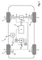
図1は、自動車1の簡略図である。自動車1は、本実施形態では4つの車輪2と3を有し、この場合車輪2は前車軸4に付設され、車輪3は後車軸5に付設されている。さらに、自動車1は駆動機7を備えた駆動装置6を有し、駆動機は、本実施形態では、発電機で作動可能な電気駆動機7である。駆動機7は、差動装置8と軸9,10,11とによって前車軸4の車輪2と結合され、その結果車輪2は駆動機7によって駆動可能である。
Figure 1 is a simplified diagram of a vehicle 1. The vehicle 1 has, in this embodiment, four
自動車1は、さらに、ブレーキ装置12を有している。ブレーキ装置12は4つの摩擦ブレーキ機構13を有し、この場合車輪2と3のそれぞれに、これら摩擦ブレーキ機構13のうちのそれぞれ1つの他の摩擦ブレーキ機構が付設されている。摩擦ブレーキ機構13を操作するために、ブレーキ装置12はブレーキマスタシリンダ14を有し、ブレーキマスタシリンダは、本実施形態ではタンデムブレーキマスタシリンダ14として形成され、その結果ブレーキマスタシリンダ14内には、図示していない2つの液圧ピストンが変位可能に支持されている。ブレーキマスタシリンダ14は、摩擦ブレーキ機構13のスレーブシリンダと流動技術的に結合されている。
The motor vehicle 1 further comprises a
ブレーキマスタシリンダ14には、ブレーキ力発生器15が付設されている。ブレーキ力発生器15は、起動可能な電動機を有している。電動機は、当該電動機の起動の際に液圧ピストンを変位させるように液圧ピストンと連結されている。
The
自動車1は、さらに、制御器17を備えた装置16を有している。制御器17は通信技術的に駆動機7と結合され、駆動機7を起動させるために形成されている。また、制御器17は通信技術的にブレーキ力発生器15と結合され、ブレーキ力発生器15またはブレーキ力発生器15の電動機を起動させるために形成されている。
The vehicle 1 further comprises a
自動車1は、さらに、第1の調整要素18を有している。第1の調整要素18はペダルとして形成され、第1の端部位置と第2の端部位置との間で無段階に移動可能である。その際、第1の端部位置における第1の調整要素18の位置は、第1の端部位置から第2の端部位置への調整距離に関して0%のパーセント値に相当している。第2の端部位置では、第1の調整要素18の位置は100%のパーセント値に相当している。第1の調整要素18は通信技術的に制御器17と結合され、その結果制御器17には、第1の調整要素18の現在位置が提供される。制御器17は、第1の調整要素18の端部位置間に設置される仮想交替位置を設定する。
The vehicle 1 further comprises a
第1の調整要素18の位置が交替位置を越えると、制御器17は自動車1に対し加速値を与える。このとき、第1の調整要素18の現在位置は交替位置と第2の端部位置との間に設置されている加速範囲内にある。加速値が設定されると、制御器17は、自動車1が加速されるように駆動機7を起動させる。
When the position of the
第1の調整要素18の位置が交替位置を下回ると、制御器17は自動車1に対し第1の減速値を設定する。このとき、現在位置は第1の端部位置と交替位置との間に設置されている減速範囲内にある。第1の減速値が自動車1に対し設定されると、制御器17は、液圧ピストンが第1の減速値の大きさに依存して変位されるようにブレーキ力発生器15を起動させる。第1の減速値が増大すると、液圧ピストンの変位の程度も増大する。
When the position of the first adjusting
液圧ピストンが変位すると、自動車1は減速され、この場合自動車1の減速の程度は液圧ピストンの変位の程度と対応している。液圧ピストンの変位により、作動液がブレーキマスタシリンダ14から搬送される。好ましくは、自動車1は摩擦ブレーキ機構13の操作によって減速される。このため、作動液をスレーブシリンダ内へ搬送する。これとは択一的に、自動車1は好ましくは駆動機7の発電機作動によって減速される。この事例では、摩擦ブレーキ機構13の操作を阻止するため、作動液を少なくとも1つの図示していない低圧流体アキュムレータ内へ搬送する。
When the hydraulic piston is displaced, the vehicle 1 is decelerated, the degree of deceleration of the vehicle 1 corresponding to the degree of displacement of the hydraulic piston. Due to the displacement of the hydraulic piston, hydraulic fluid is conveyed from the
自動車1は、さらに、第2の調整要素19を有し、第2の調整要素はブレーキペダル19である。ブレーキペダル19は、第3の端部位置と第4の端部位置との間で無段階に移動可能である。その際、第3の端部位置でのブレーキペダル19の位置は、第3の端部位置から第4の端部位置への調整距離に関して0%のパーセント値に相当している。第4の端部位置では、ブレーキペダル19の位置は100%のパーセント値に相当している。
The vehicle 1 further has a
ブレーキペダル19にはばね機構20が付設され、ばね機構はブレーキペダル19を第3の端部位置の方向に、特に第3の端部位置まで押している。したがって、ブレーキペダル19はばね機構20のばね力に抗して第4の端部位置の方向に移動可能であり、その結果ばね力は、ブレーキペダル19を第4の端部位置の方向に移動させるために克服しなければならない反力である。ばね機構20は、一方ではブレーキペダル19と、他方では図示していないハウジング、特にブレーキ力発生器15のハウジングとの間で、予め緊張させて保持されている。したがってばね機構20は、一方では直接にまたはブレーキペダル19で間接的に支持され、他方では直接にまたはハウジングで間接的に支持されている。
A
ブレーキペダル19は、自動車1のドライバーによって操作可能である。ブレーキペダル19の操作とは、ドライバーがブレーキペダル19を次のように操作力で付勢すること、すなわちブレーキペダル19が非操作状態で占める位置と比べて、ブレーキペダル19が第4の端部位置の方向に変位するように操作力で付勢することと理解される。
The
本実施形態では、ブレーキペダル19は次のように液圧ピストンと機械的に連結されており、すなわちブレーキペダル19が操作されると、液圧ピストンが前記機械的な連結によって変位するように液圧ピストンと機械的に連結されている。他の実施例によれば、ブレーキペダル19と液圧ピストンとの間のこの種の機械的連結が省略される。
In this embodiment, the
本実施形態では、ブレーキペダル19は変位可能に支持されているブレーキ力発生器15の操作要素と次のように連結されており、すなわち液圧ピストンが変位するようにブレーキ力発生器15を起動したときに、ブレーキペダル19が第4の端部位置の方向に移動するように連結されている。対応的に、非操作状態でのブレーキペダル19の位置は可変であり、第1の減速値の大きさによって影響を受け、したがってブレーキ力発生器19の起動または液圧ピストンの変位の程度によって影響を受ける。
In this embodiment, the
ブレーキペダル19は通信技術的に制御器17と結合され、その結果制御器17には、ブレーキペダル19の操作の程度またはブレーキペダル19の現在位置が提供される。ブレーキペダル19を操作すると、制御器17は自動車1に対し第2の減速値を設定する。自動車1に対する第2の減速値が設定されると、制御器17はブレーキ力発生器15を次のように起動させ、すなわち液圧ピストンが第2の減速値の大きさに依存して変位するように起動させる。第2の減速値が増大すると、液圧ピストンの変位の程度も増大する。
The
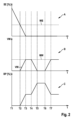
次に、図2に関して、自動車1を作動させる有利な方法を説明する。このため、図2は第1のグラフA、第2のグラフB、第3のグラフCを示している。 Now, with reference to Fig. 2, an advantageous method of operating the vehicle 1 will be described. For this purpose, Fig. 2 shows a first graph A, a second graph B and a third graph C.
第1のグラフAでは、第1の調整要素18の位置のパーセント値が時間tに依存して図示されている。第2のグラフBでは、第1の減速値VWが時間tに依存して図示されている。第3のグラフCでは、ブレーキペダル19の位置のパーセント値が図示されている。
In the first graph A, the percentage value of the position of the first adjusting
第1の時点T1と第2の時点T2の間で、第1の調整要素18の位置は加速範囲にある。対応的に、時点T1とT2の間では、第1の減速値VWは設定されない。ブレーキペダル19の位置は第3の端部位置に対応している。
Between the first time T1 and the second time T2, the position of the first adjusting
第2の時点T2と第3の時点T3の間では、第1の調整要素18は交替位置WSから出発して第1の端部位置へ移動し、その結果第3の時点T3で、第1の調整要素18の位置は第1の端部位置に対応している。以下では、第1の調整要素18の位置は一定に保持される。時点T2とT3の間での第1の調整要素18の位置は減速範囲にあるので、制御器17は第1の減速値VWを設定する。第1の端部位置への第1の調整要素18の移動のために、時点T2とT3の間では、第1の減速値VWの大きさが第1の減速値の大きさまで連続的に上昇して最大値MWに達する。第1の減速値VWの設定に基づき、制御器17は、ブレーキ力発生器15が液圧ピストンを変位させるように第2の時点T2からブレーキ力発生器15を起動させる。その際、液圧ピストンの変位の程度は第1の減速値VWの大きさと対応している。第1の減速値VWが大きくなると、液圧ピストンの変位の程度も大きくなる。ブレーキペダル19と液圧ピストンおよび/またはブレーキ力発生器15の操作要素との連結のために、ブレーキペダル19は第4の端部位置の方向に移動する。その際、ドライバーによる操作力は提供されない。この限りでは、ブレーキペダル19は時点T2とT3の間で非操作状態にある。
Between the second time T2 and the third time T3, the first adjusting
第4の時点T4から、ブレーキペダル19がドライバーによって操作される。すなわち、ドライバーは反力を上回る操作力を提供し、その結果ブレーキペダル19はドライバーによって第4の端部位置の方向に移動する。第4の時点T4と第5の時点T5の間で、ブレーキペダル19は連続的に第4の端部位置の方向に移動し、その結果ブレーキペダル19の位置のパーセント値が連続的に上昇する。ブレーキペダル19の操作は制御器17によって検知される。その結果、制御器17は時点T4とT5の間で第1の減速値VWの大きさを連続的に減少させる。
From the fourth time point T4, the
第6の時点T6から、ブレーキペダル19の操作の程度が減少する。すなわちブレーキペダル19は、当該ブレーキペダル19が第7の時点T7で再び非操作状態になるまで、反力によって再び第3の端部位置の方向に移動する。ブレーキペダル19の操作の減少は制御器17によって検知される。その結果、制御器17は時点T6とT7の間で第1の減速値VWの大きさを連続的に増大させる。
From the sixth time point T6, the degree of operation of the
ブレーキペダル19が時点T4とT7の間で操作されるため、制御器17はこれらの時点の間で第2の減速値をも設定する。しかし、図2では、第2の減速値の経過は見やすくするために図示していない。
Since the
図3は、種々の減速度・反力特性曲線を図示した第4のグラフDを示している。減速度・反力特性曲線とは、ばね機構20によって提供される反力Fに依存する自動車1の減速度Vを記述する特性曲線である。
Figure 3 shows a fourth graph D illustrating various deceleration-reaction force characteristic curves. The deceleration-reaction force characteristic curves are characteristic curves that describe the deceleration V of the vehicle 1 depending on the reaction force F provided by the
第1の減速度・反力特性曲線L1は、第1の調整要素18のワンペダル機能が作動していない時の、または、ワンペダル機能を備えた第1の調整要素が設けられていない時の、ばね機構20によって提供される反力Fに依存する自動車1の減速度を記述している。ワンペダル機能が作動していなければ、第1の調整要素18の操作時には、従来のアクセルペダルによって知られているように常に加速値が設定される。図3から明らかなように、自動車1の減速を増すためには、ドライバーはこれまで操作されなかった第2の調整要素19から出発して、特定の第1の値W1を持つ反力を克服しなければならない。
The first deceleration/reaction force characteristic curve L1 describes the deceleration of the vehicle 1 as a function of the reaction force F provided by the
第2の減速度・反力特性曲線L2は、第1の調整要素18のワンペダル機能が作動している時の、ばね機構20によって提供される反力Fに依存する自動車1の減速度Vを記述している。その際、第1の調整要素18の位置は減速範囲にある。この限りでは、第1の減速値VWが設定され、自動車1は減速される。ブレーキペダル19の操作時に第1の減速値VWが減らなければ、特性曲線L2から見て取れるように、自動車1の減速度Vを増すためにドライバーは特定の第2の値W2を持つ反力を克服しなければならない。値W2は、値W1よりも明らかに大きい。ドライバーは、自動車1の減速度Vを増すような大きな反力Fを克服しなければならないことに慣れていない。
The second deceleration/reaction force characteristic curve L2 describes the deceleration V of the vehicle 1 depending on the reaction force F provided by the
第3の減速度・反力特性曲線L3も、第1の調整要素18のワンペダル機能が作動している時に、提供される反力Fに依存する自動車1の減速度Vを記述している。第3の減速度・反力特性曲線L3の事例でも、第1の調整要素18の位置は減速範囲にあり、その結果第1の減速値VWが設定されて、自動車1は減速される。しかし、ドライバーが反力Fを克服し、したがってブレーキペダル19を操作すれば、以前に図2に関して説明したように、第1の減速値VWは減少する。その結果、自動車1の減速度Vも一時的に減少する。それ故ドライバーは、自動車1の減速度Vを増すために、第1の値W1と第2の値W2との間にある特定の第3の値W3を持つ反力を克服するだけでよい。ドライバーが値W2を持つ反力を克服すれば、第2の減速値の増大が第1の減速値VWの減少よりも優勢になり、その結果総じて車両の減速度Vが上昇する。第3の値W3は第2の値W2よりも小さいので、ドライバーには、第2の特性曲線L2によるブレーキペダル19の操作よりも、第3の特性曲線L3によるブレーキペダル19の操作のほうが快適に思われる。
The third deceleration-reaction force characteristic curve L3 also describes the deceleration V of the vehicle 1 depending on the reaction force F provided when the one-pedal function of the first adjusting
1 自動車
7 電気駆動機(電気機械)
12 ブレーキ装置
13 摩擦ブレーキ機構
14 ブレーキマスタシリンダ
15 ブレーキ力発生器
16 装置
17 制御器
18 ペダル(第1の調整要素)
19 ブレーキペダル(第2の調整要素)
VW 第1の減速値
WS 交替位置
1 Automobiles 7 Electric drives (electrical machines)
12
19 Brake pedal (second adjustment element)
VW First deceleration value WS Alternating position
Claims (8)
前記第2の調整要素(19)の操作の際、第2の減速値を設定し、前記第2の減速値の設定の際、前記液圧ピストンが前記第2の減速値の大きさに依存して変位するように前記ブレーキ力発生器(15)を起動させることを特徴とする方法。 A method for operating a motor vehicle, the motor vehicle (1) having a first adjusting element (18), an operable second adjusting element (19), a braking system (12) with an actuatable brake force generator (15) and a brake master cylinder (14), in which at least one hydraulic piston is displaceably supported, the first adjusting element (18) being in particular infinitely movable between a first end position and a second end position, an alternating position (WS) being set between the first end position and the second end position, and a current position of the first adjusting element (18) being changed to the alternating position (WS) being changed to the alternating position (WS). a first deceleration value (VW) for the vehicle (1) if the current position exceeds the replacement position (WS), and a second deceleration value (VW) for the vehicle (1) is set if the current position falls below the replacement position (WS), and when setting the first deceleration value (VW), activate the braking force generator (15) such that the hydraulic piston is displaced depending on the magnitude of the first deceleration value (VW), and when operating the second adjusting element (19) by the driver of the vehicle (1), the method further comprises : reducing the first deceleration value (VW) when detecting an operation of the second adjusting element (19) by the driver of the vehicle (1);
a second deceleration value is set during actuation of the second adjusting element (19), and the brake force generator (15) is activated during the setting of the second deceleration value such that the hydraulic piston is displaced in dependence on the magnitude of the second deceleration value .
8. A motor vehicle comprising a first adjusting element (18), which is in particular infinitely movable between a first end position and a second end position, an actuable second adjusting element (19), and a brake device (12), the brake device (12) having an actuatable brake force generator (15) and a brake master cylinder (14), in which at least one hydraulic piston is displaceably supported, characterized in that the device (16) according to claim 7 is provided .
Applications Claiming Priority (3)
| Application Number | Priority Date | Filing Date | Title |
|---|---|---|---|
| DE102020206139.4A DE102020206139A1 (en) | 2020-05-15 | 2020-05-15 | Method for operating a motor vehicle, device, motor vehicle |
| DE102020206139.4 | 2020-05-15 | ||
| PCT/EP2021/061974 WO2021228674A1 (en) | 2020-05-15 | 2021-05-06 | Method for operating a motor vehicle, device, and motor vehicle |
Publications (2)
| Publication Number | Publication Date |
|---|---|
| JP2023525131A JP2023525131A (en) | 2023-06-14 |
| JP7581378B2 true JP7581378B2 (en) | 2024-11-12 |
Family
ID=75919302
Family Applications (1)
| Application Number | Title | Priority Date | Filing Date |
|---|---|---|---|
| JP2022568860A Active JP7581378B2 (en) | 2020-05-15 | 2021-05-06 | Method and device for operating a motor vehicle, motor vehicle |
Country Status (5)
| Country | Link |
|---|---|
| US (1) | US12612022B2 (en) |
| JP (1) | JP7581378B2 (en) |
| CN (1) | CN115515829B (en) |
| DE (1) | DE102020206139A1 (en) |
| WO (1) | WO2021228674A1 (en) |
Citations (9)
| Publication number | Priority date | Publication date | Assignee | Title |
|---|---|---|---|---|
| JP2006137324A (en) | 2004-11-12 | 2006-06-01 | Toyota Motor Corp | Acceleration / deceleration controller |
| JP2015063202A (en) | 2013-09-25 | 2015-04-09 | 日産自動車株式会社 | Longitudinal acceleration control device |
| WO2016158508A1 (en) | 2015-03-31 | 2016-10-06 | 日立オートモティブシステムズ株式会社 | Brake control device |
| WO2017002557A1 (en) | 2015-06-30 | 2017-01-05 | 日立オートモティブシステムズ株式会社 | Acceleration and deceleration control device |
| JP2017165151A (en) | 2016-03-14 | 2017-09-21 | 本田技研工業株式会社 | Electric vehicle braking device |
| WO2019151208A1 (en) | 2018-02-02 | 2019-08-08 | マツダ株式会社 | Vehicular control method, vehicular system, and vehicular control device |
| JP2020067041A (en) | 2018-10-25 | 2020-04-30 | トヨタ自動車株式会社 | Vehicular control apparatus |
| JP2021024332A (en) | 2019-07-31 | 2021-02-22 | トヨタ自動車株式会社 | Acceleration-deceleration control apparatus |
| JP2022155157A (en) | 2021-03-30 | 2022-10-13 | トヨタ自動車株式会社 | Vehicle control device |
Family Cites Families (8)
| Publication number | Priority date | Publication date | Assignee | Title |
|---|---|---|---|---|
| JP4415617B2 (en) * | 2003-09-11 | 2010-02-17 | 株式会社アドヴィックス | Brake control device |
| DE102009047615A1 (en) * | 2009-12-08 | 2011-06-09 | Robert Bosch Gmbh | Method for operating a brake system of a vehicle, brake system |
| DE102010042694B4 (en) * | 2010-07-27 | 2025-07-10 | Robert Bosch Gmbh | Coupling device for connecting a brake input element to a master brake cylinder and method for operating such a coupling device |
| DE102015000594A1 (en) | 2015-01-16 | 2016-07-21 | Knorr-Bremse Systeme für Nutzfahrzeuge GmbH | Brake system for a vehicle and method for operating a brake system for a vehicle |
| DE102015211359A1 (en) * | 2015-06-19 | 2017-01-05 | Volkswagen Aktiengesellschaft | Preparation of a braking process in a motor vehicle |
| DE102016223760A1 (en) * | 2016-11-30 | 2018-05-30 | Robert Bosch Gmbh | Master brake cylinder, brake system |
| DE202019102503U1 (en) * | 2019-05-03 | 2019-05-13 | Robert Bosch Gmbh | Brake system for a motor vehicle, motor vehicle |
| DE102019006392A1 (en) | 2019-09-10 | 2020-03-26 | Daimler Ag | Pedal arrangement for a motor vehicle with at least one foot pedal, which is brought into a stowed position and into an operating position, and method |
-
2020
- 2020-05-15 DE DE102020206139.4A patent/DE102020206139A1/en active Pending
-
2021
- 2021-05-06 CN CN202180035029.1A patent/CN115515829B/en active Active
- 2021-05-06 JP JP2022568860A patent/JP7581378B2/en active Active
- 2021-05-06 WO PCT/EP2021/061974 patent/WO2021228674A1/en not_active Ceased
- 2021-05-06 US US17/996,818 patent/US12612022B2/en active Active
Patent Citations (9)
| Publication number | Priority date | Publication date | Assignee | Title |
|---|---|---|---|---|
| JP2006137324A (en) | 2004-11-12 | 2006-06-01 | Toyota Motor Corp | Acceleration / deceleration controller |
| JP2015063202A (en) | 2013-09-25 | 2015-04-09 | 日産自動車株式会社 | Longitudinal acceleration control device |
| WO2016158508A1 (en) | 2015-03-31 | 2016-10-06 | 日立オートモティブシステムズ株式会社 | Brake control device |
| WO2017002557A1 (en) | 2015-06-30 | 2017-01-05 | 日立オートモティブシステムズ株式会社 | Acceleration and deceleration control device |
| JP2017165151A (en) | 2016-03-14 | 2017-09-21 | 本田技研工業株式会社 | Electric vehicle braking device |
| WO2019151208A1 (en) | 2018-02-02 | 2019-08-08 | マツダ株式会社 | Vehicular control method, vehicular system, and vehicular control device |
| JP2020067041A (en) | 2018-10-25 | 2020-04-30 | トヨタ自動車株式会社 | Vehicular control apparatus |
| JP2021024332A (en) | 2019-07-31 | 2021-02-22 | トヨタ自動車株式会社 | Acceleration-deceleration control apparatus |
| JP2022155157A (en) | 2021-03-30 | 2022-10-13 | トヨタ自動車株式会社 | Vehicle control device |
Also Published As
| Publication number | Publication date |
|---|---|
| DE102020206139A1 (en) | 2021-11-18 |
| CN115515829A (en) | 2022-12-23 |
| JP2023525131A (en) | 2023-06-14 |
| US20230202443A1 (en) | 2023-06-29 |
| US12612022B2 (en) | 2026-04-28 |
| CN115515829B (en) | 2025-06-06 |
| WO2021228674A1 (en) | 2021-11-18 |
Similar Documents
| Publication | Publication Date | Title |
|---|---|---|
| CN102442288B (en) | Brakes and the method for operation brake system of car for automobile | |
| KR102113933B1 (en) | Brake system and method for operating a brake system | |
| KR102187995B1 (en) | Brake control device | |
| CN111094089B (en) | Electric booster | |
| CN103003115A (en) | Brake system for a vehicle and method for operating a brake system for a vehicle | |
| US20150066326A1 (en) | Brake System, Brake Apparatus, and Method for Controlling Brake System | |
| JP2010531768A (en) | Hydraulic brake device control system | |
| CN103702874A (en) | Control device for brake system of vehicle, brake system for vehicle and method for operating brake system of vehicle | |
| CN107709125A (en) | Acceleration/deceleration control device | |
| JP6737733B2 (en) | Vehicle braking control device | |
| JP2001522747A (en) | Automobile with automated actuation of the clutch | |
| JP2002517352A (en) | Apparatus and method for controlling a vehicle brake system | |
| JP2024506568A (en) | Method and braking system for braking a vehicle | |
| KR20070007145A (en) | How to operate the operating unit for the automobile brake system | |
| JP2003025985A (en) | VEHICLE BRAKE HYDRAULIC GENERATION DEVICE, AND HYDRAULIC BRAKE DEVICE HAVING THE HYDRAULIC GENERATION DEVICE | |
| CN115515829B (en) | Method, device and motor vehicle for operating a motor vehicle | |
| CN111886164B (en) | Method for regulating the drive power of an electronically controllable motor | |
| GB2419164A (en) | Brake system having a settable braking characteristic | |
| JP2023118085A (en) | method of driving a car, control device, car | |
| CN112601683B (en) | Method for determining a starting time point for a reloading process in a plunger device of an electronic slip-adjustable power-assisted brake system | |
| US11975698B2 (en) | Method for controlling an electronically slip-controllable externally powered brake system, in particular for a motor vehicle, and electronically slip-controllable externally powered brake system, in particular for a motor vehicle | |
| CN113242822B (en) | Method and device for operating a brake system, brake system | |
| WO2012161016A1 (en) | Stroke simulator, master cylinder having stroke simulator, and brake system using master cylinder | |
| KR102487781B1 (en) | Regenerative braking system for a vehicle and method for operating the regenerative braking system in a vehicle | |
| WO2021039535A1 (en) | Electric booster device for vehicle |
Legal Events
| Date | Code | Title | Description |
|---|---|---|---|
| A621 | Written request for application examination |
Free format text: JAPANESE INTERMEDIATE CODE: A621 Effective date: 20221111 |
|
| A131 | Notification of reasons for refusal |
Free format text: JAPANESE INTERMEDIATE CODE: A131 Effective date: 20240126 |
|
| A601 | Written request for extension of time |
Free format text: JAPANESE INTERMEDIATE CODE: A601 Effective date: 20240403 |
|
| A601 | Written request for extension of time |
Free format text: JAPANESE INTERMEDIATE CODE: A601 Effective date: 20240624 |
|
| A521 | Request for written amendment filed |
Free format text: JAPANESE INTERMEDIATE CODE: A523 Effective date: 20240723 |
|
| TRDD | Decision of grant or rejection written | ||
| A01 | Written decision to grant a patent or to grant a registration (utility model) |
Free format text: JAPANESE INTERMEDIATE CODE: A01 Effective date: 20241009 |
|
| A61 | First payment of annual fees (during grant procedure) |
Free format text: JAPANESE INTERMEDIATE CODE: A61 Effective date: 20241030 |
|
| R150 | Certificate of patent or registration of utility model |
Ref document number: 7581378 Country of ref document: JP Free format text: JAPANESE INTERMEDIATE CODE: R150 |