JP7581372B2 - End cap assembly, battery cell, battery and battery cell manufacturing method and apparatus - Google Patents
End cap assembly, battery cell, battery and battery cell manufacturing method and apparatus Download PDFInfo
- Publication number
- JP7581372B2 JP7581372B2 JP2022563184A JP2022563184A JP7581372B2 JP 7581372 B2 JP7581372 B2 JP 7581372B2 JP 2022563184 A JP2022563184 A JP 2022563184A JP 2022563184 A JP2022563184 A JP 2022563184A JP 7581372 B2 JP7581372 B2 JP 7581372B2
- Authority
- JP
- Japan
- Prior art keywords
- end cap
- stopper
- thickness direction
- battery cell
- hole
- Prior art date
- Legal status (The legal status is an assumption and is not a legal conclusion. Google has not performed a legal analysis and makes no representation as to the accuracy of the status listed.)
- Active
Links
Images


Classifications
-
- H—ELECTRICITY
- H01—ELECTRIC ELEMENTS
- H01M—PROCESSES OR MEANS, e.g. BATTERIES, FOR THE DIRECT CONVERSION OF CHEMICAL ENERGY INTO ELECTRICAL ENERGY
- H01M50/00—Constructional details or processes of manufacture of the non-active parts of electrochemical cells other than fuel cells, e.g. hybrid cells
- H01M50/10—Primary casings; Jackets or wrappings
- H01M50/147—Lids or covers
-
- H—ELECTRICITY
- H01—ELECTRIC ELEMENTS
- H01M—PROCESSES OR MEANS, e.g. BATTERIES, FOR THE DIRECT CONVERSION OF CHEMICAL ENERGY INTO ELECTRICAL ENERGY
- H01M50/00—Constructional details or processes of manufacture of the non-active parts of electrochemical cells other than fuel cells, e.g. hybrid cells
- H01M50/50—Current conducting connections for cells or batteries
- H01M50/572—Means for preventing undesired use or discharge
- H01M50/584—Means for preventing undesired use or discharge for preventing incorrect connections inside or outside the batteries
- H01M50/59—Means for preventing undesired use or discharge for preventing incorrect connections inside or outside the batteries characterised by the protection means
-
- H—ELECTRICITY
- H01—ELECTRIC ELEMENTS
- H01M—PROCESSES OR MEANS, e.g. BATTERIES, FOR THE DIRECT CONVERSION OF CHEMICAL ENERGY INTO ELECTRICAL ENERGY
- H01M50/00—Constructional details or processes of manufacture of the non-active parts of electrochemical cells other than fuel cells, e.g. hybrid cells
- H01M50/10—Primary casings; Jackets or wrappings
- H01M50/102—Primary casings; Jackets or wrappings characterised by their shape or physical structure
- H01M50/103—Primary casings; Jackets or wrappings characterised by their shape or physical structure prismatic or rectangular
-
- H—ELECTRICITY
- H01—ELECTRIC ELEMENTS
- H01M—PROCESSES OR MEANS, e.g. BATTERIES, FOR THE DIRECT CONVERSION OF CHEMICAL ENERGY INTO ELECTRICAL ENERGY
- H01M10/00—Secondary cells; Manufacture thereof
- H01M10/05—Accumulators with non-aqueous electrolyte
- H01M10/052—Li-accumulators
- H01M10/0525—Rocking-chair batteries, i.e. batteries with lithium insertion or intercalation in both electrodes; Lithium-ion batteries
-
- H—ELECTRICITY
- H01—ELECTRIC ELEMENTS
- H01M—PROCESSES OR MEANS, e.g. BATTERIES, FOR THE DIRECT CONVERSION OF CHEMICAL ENERGY INTO ELECTRICAL ENERGY
- H01M50/00—Constructional details or processes of manufacture of the non-active parts of electrochemical cells other than fuel cells, e.g. hybrid cells
- H01M50/10—Primary casings; Jackets or wrappings
- H01M50/147—Lids or covers
- H01M50/148—Lids or covers characterised by their shape
- H01M50/15—Lids or covers characterised by their shape for prismatic or rectangular cells
-
- H—ELECTRICITY
- H01—ELECTRIC ELEMENTS
- H01M—PROCESSES OR MEANS, e.g. BATTERIES, FOR THE DIRECT CONVERSION OF CHEMICAL ENERGY INTO ELECTRICAL ENERGY
- H01M50/00—Constructional details or processes of manufacture of the non-active parts of electrochemical cells other than fuel cells, e.g. hybrid cells
- H01M50/10—Primary casings; Jackets or wrappings
- H01M50/183—Sealing members
- H01M50/186—Sealing members characterised by the disposition of the sealing members
-
- H—ELECTRICITY
- H01—ELECTRIC ELEMENTS
- H01M—PROCESSES OR MEANS, e.g. BATTERIES, FOR THE DIRECT CONVERSION OF CHEMICAL ENERGY INTO ELECTRICAL ENERGY
- H01M50/00—Constructional details or processes of manufacture of the non-active parts of electrochemical cells other than fuel cells, e.g. hybrid cells
- H01M50/50—Current conducting connections for cells or batteries
- H01M50/531—Electrode connections inside a battery casing
-
- H—ELECTRICITY
- H01—ELECTRIC ELEMENTS
- H01M—PROCESSES OR MEANS, e.g. BATTERIES, FOR THE DIRECT CONVERSION OF CHEMICAL ENERGY INTO ELECTRICAL ENERGY
- H01M50/00—Constructional details or processes of manufacture of the non-active parts of electrochemical cells other than fuel cells, e.g. hybrid cells
- H01M50/50—Current conducting connections for cells or batteries
- H01M50/543—Terminals
-
- H—ELECTRICITY
- H01—ELECTRIC ELEMENTS
- H01M—PROCESSES OR MEANS, e.g. BATTERIES, FOR THE DIRECT CONVERSION OF CHEMICAL ENERGY INTO ELECTRICAL ENERGY
- H01M50/00—Constructional details or processes of manufacture of the non-active parts of electrochemical cells other than fuel cells, e.g. hybrid cells
- H01M50/50—Current conducting connections for cells or batteries
- H01M50/572—Means for preventing undesired use or discharge
- H01M50/584—Means for preventing undesired use or discharge for preventing incorrect connections inside or outside the batteries
- H01M50/586—Means for preventing undesired use or discharge for preventing incorrect connections inside or outside the batteries inside the batteries, e.g. incorrect connections of electrodes
-
- H—ELECTRICITY
- H01—ELECTRIC ELEMENTS
- H01M—PROCESSES OR MEANS, e.g. BATTERIES, FOR THE DIRECT CONVERSION OF CHEMICAL ENERGY INTO ELECTRICAL ENERGY
- H01M50/00—Constructional details or processes of manufacture of the non-active parts of electrochemical cells other than fuel cells, e.g. hybrid cells
- H01M50/60—Arrangements or processes for filling or topping-up with liquids; Arrangements or processes for draining liquids from casings
- H01M50/609—Arrangements or processes for filling with liquid, e.g. electrolytes
- H01M50/627—Filling ports
- H01M50/636—Closing or sealing filling ports, e.g. using lids
-
- H—ELECTRICITY
- H01—ELECTRIC ELEMENTS
- H01M—PROCESSES OR MEANS, e.g. BATTERIES, FOR THE DIRECT CONVERSION OF CHEMICAL ENERGY INTO ELECTRICAL ENERGY
- H01M2220/00—Batteries for particular applications
- H01M2220/20—Batteries in motive systems, e.g. vehicle, ship, plane
-
- H—ELECTRICITY
- H01—ELECTRIC ELEMENTS
- H01M—PROCESSES OR MEANS, e.g. BATTERIES, FOR THE DIRECT CONVERSION OF CHEMICAL ENERGY INTO ELECTRICAL ENERGY
- H01M2220/00—Batteries for particular applications
- H01M2220/30—Batteries in portable systems, e.g. mobile phone, laptop
-
- Y—GENERAL TAGGING OF NEW TECHNOLOGICAL DEVELOPMENTS; GENERAL TAGGING OF CROSS-SECTIONAL TECHNOLOGIES SPANNING OVER SEVERAL SECTIONS OF THE IPC; TECHNICAL SUBJECTS COVERED BY FORMER USPC CROSS-REFERENCE ART COLLECTIONS [XRACs] AND DIGESTS
- Y02—TECHNOLOGIES OR APPLICATIONS FOR MITIGATION OR ADAPTATION AGAINST CLIMATE CHANGE
- Y02E—REDUCTION OF GREENHOUSE GAS [GHG] EMISSIONS, RELATED TO ENERGY GENERATION, TRANSMISSION OR DISTRIBUTION
- Y02E60/00—Enabling technologies; Technologies with a potential or indirect contribution to GHG emissions mitigation
- Y02E60/10—Energy storage using batteries
Landscapes
- Chemical & Material Sciences (AREA)
- Chemical Kinetics & Catalysis (AREA)
- Electrochemistry (AREA)
- General Chemical & Material Sciences (AREA)
- Engineering & Computer Science (AREA)
- Materials Engineering (AREA)
- Manufacturing & Machinery (AREA)
- Connection Of Batteries Or Terminals (AREA)
- Sealing Battery Cases Or Jackets (AREA)
- Filling, Topping-Up Batteries (AREA)
Description
本出願は、電池技術分野に関し、具体的に言えば、エンドキャップアセンブリ、電池セル、電池及び電池セルの製造方法と機器に関する。 This application relates to the field of battery technology, and more particularly to end cap assemblies, battery cells, and methods and apparatus for manufacturing batteries and battery cells.
現在、車両に多く使用されている電池としては、リチウムイオン電池が一般的であり、リチウムイオン電池は、再充電可能な電池として、体積が小さく、エネルギー密度が高く、パワー密度が高く、サイクル使用回数が多く、保管時間が長いなどの利点を有する。 Currently, lithium-ion batteries are the most commonly used type of battery in vehicles. As a rechargeable battery, lithium-ion batteries have the advantages of being small in volume, having a high energy density, high power density, many cycles, and a long storage time.
再充電可能な電池セルは、一般的には、ケースと、エンドキャップアセンブリと、電極アセンブリとを含み、電極アセンブリは、ケース内に位置し、エンドキャップアセンブリは、ケースにキャッピングされて、電極アセンブリのために密閉環境を提供する。 A rechargeable battery cell typically includes a case, an end cap assembly, and an electrode assembly, where the electrode assembly is located within the case and the end cap assembly is capped to the case to provide a sealed environment for the electrode assembly.
一般的な電池セルでは、使用中に正負極の短絡が発生しやすい。 In typical battery cells, short circuits between the positive and negative electrodes can easily occur during use.
本出願の実施例は、電池セルの正負極が短絡するリスクを効果的に低減することができるエンドキャップアセンブリ、電池セル、電池及び電池セルの製造方法と機器を提供する。 The embodiments of the present application provide an end cap assembly, a battery cell, a battery, and a method and apparatus for manufacturing a battery cell that can effectively reduce the risk of short-circuiting the positive and negative terminals of a battery cell.
第1の態様によれば、本出願の実施例は、タブを有する電極アセンブリを含む電池セルに用いられるエンドキャップアセンブリを提供し、エンドキャップアセンブリは、注入孔が設置されているエンドキャップであって、前記注入孔は前記エンドキャップの厚さ方向において前記エンドキャップを貫通するエンドキャップと、前記エンドキャップの前記厚さ方向における一方側に設けられるように構成される絶縁部材であって、前記絶縁部材には貫通孔が設置されており、前記貫通孔は前記厚さ方向において前記絶縁部材を貫通する絶縁部材と、排液口が設置されており、前記注入孔と前記貫通孔を経由した流体媒体を、流れ方向を変えた後に前記排液口を通過して前記電池セルの内部に入らせるように構成されるストッパ部材と、前記タブが前記貫通孔を貫通して前記エンドキャップと接触することを阻止するために、前記タブと前記エンドキャップを仕切るように構成される仕切り部材とを含む。 According to a first aspect, an embodiment of the present application provides an end cap assembly for use in a battery cell including an electrode assembly having a tab, the end cap assembly including: an end cap having an injection hole, the injection hole penetrating the end cap in a thickness direction of the end cap; an insulating member configured to be provided on one side of the end cap in the thickness direction, the insulating member having a through hole, the through hole penetrating the insulating member in the thickness direction; a stopper member having a drainage hole, configured to allow a fluid medium passing through the injection hole and the through hole to pass through the drainage hole and enter the inside of the battery cell after changing its flow direction; and a partition member configured to separate the tab from the end cap to prevent the tab from penetrating the through hole and coming into contact with the end cap.
上記技術案では、ストッパ部材は、流体媒体(例えば、電解液)の流れ方向を変える役割を果たし、注入孔を介して電池セルの内部に流体媒体を注入する場合、流体媒体がエンドキャップにおける注入孔と絶縁部材における貫通孔を経由した後、流体媒体は、ストッパ部材のストッパ作用で方向を変え、且つストッパ部材の排液口から電池セルの内部に入り、流体媒体による電池セルの内部の電極アセンブリのセパレータへの衝撃力を減少させ、電極アセンブリの正極板と負極板が互いに接触して短絡を引き起こすリスクを低減した。なお、仕切り部材は、タブが絶縁部材における貫通孔を貫通してエンドキャップと接触することを阻止するようにタブとエンドキャップを仕切る役割を果たし、タブとエンドキャップとの接触による短絡のリスクを低減した。 In the above technical proposal, the stopper member serves to change the flow direction of the fluid medium (e.g., electrolyte) and when the fluid medium is injected into the battery cell through the injection hole, the fluid medium passes through the injection hole in the end cap and the through hole in the insulating member, and then the fluid medium changes direction due to the stopping action of the stopper member and enters the battery cell through the drainage port of the stopper member, thereby reducing the impact force of the fluid medium on the separator of the electrode assembly inside the battery cell and reducing the risk of the positive and negative plates of the electrode assembly coming into contact with each other and causing a short circuit. In addition, the partition member serves to separate the tab and the end cap so as to prevent the tab from passing through the through hole in the insulating member and coming into contact with the end cap, thereby reducing the risk of a short circuit due to contact between the tab and the end cap.
いくつかの実施例において、前記厚さ方向においては、前記仕切り部材の前記絶縁部材への投影は前記貫通孔の一部を覆う。 In some embodiments, in the thickness direction, the projection of the partition member onto the insulating member covers a portion of the through hole.
上記技術案では、仕切り部材の絶縁部材への投影が貫通孔の一部を覆うことによって、仕切り部材は、注入孔と貫通孔を流れる流体媒体に対してストッパ作用を果たし、流体媒体による電極アセンブリのセパレータへの衝撃力を低減することができる。 In the above technical proposal, the projection of the partition member onto the insulating member covers part of the through hole, so that the partition member acts as a stopper against the fluid medium flowing through the injection hole and the through hole, thereby reducing the impact force of the fluid medium on the separator of the electrode assembly.
いくつかの実施例において、前記厚さ方向においては、前記ストッパ部材の前記絶縁部材への投影は前記貫通孔の一部を覆う。 In some embodiments, in the thickness direction, the projection of the stopper member onto the insulating member covers a portion of the through hole.
上記技術案では、ストッパ部材の絶縁部材への投影が貫通孔の一部を覆うことによって、ストッパ部材は、注入孔と貫通孔を流れる流体媒体に対して良好なストッパ作用を果たし、それによって流体媒体の流れ方向を変えるという目的を達成する。 In the above technical proposal, the projection of the stopper member onto the insulating member covers part of the through hole, so that the stopper member exerts an effective stopping effect on the fluid medium flowing through the injection hole and the through hole, thereby achieving the purpose of changing the flow direction of the fluid medium.
いくつかの実施例において、前記厚さ方向においては、前記仕切り部材は、前記排液口よりも前記エンドキャップに近い。 In some embodiments, the partition member is closer to the end cap in the thickness direction than the drain port.
いくつかの実施例において、前記ストッパ部材の第1の方向における少なくとも一方側には前記仕切り部材が設置されており、前記第1の方向は前記厚さ方向に垂直である。 In some embodiments, the partition member is installed on at least one side of the stopper member in a first direction, and the first direction is perpendicular to the thickness direction.
上記技術案では、ストッパ部材の第1の方向における少なくとも一方側には仕切り部材が設置されており、それによってストッパ部材と仕切り部材との全体的構造をよりコンパクトにする。 In the above technical proposal, a partition member is installed on at least one side of the stopper member in the first direction, thereby making the overall structure of the stopper member and the partition member more compact.
いくつかの実施例において、前記ストッパ部材の前記第1の方向における両側には、いずれも前記仕切り部材が設置されている。 In some embodiments, the partition members are installed on both sides of the stopper member in the first direction.
上記技術案では、ストッパ部材の第1の方向における両側には、いずれも仕切り部材が設置されており、ストッパ部材における二つの仕切り部材は、第1の方向における二つのタブをエンドキャップと仕切ることができる。 In the above technical proposal, a partition member is installed on both sides of the stopper member in the first direction, and the two partition members in the stopper member can separate the two tabs in the first direction from the end caps.
いくつかの実施例において、前記第1の方向では、前記ストッパ部材の少なくとも一方側には前記排液口が設置されており、前記タブは、前記ストッパ部材の一方側に配置され、且つ前記排液口と対向するように構成される。 In some embodiments, in the first direction, the drainage opening is provided on at least one side of the stopper member, and the tab is arranged on one side of the stopper member and configured to face the drainage opening.
上記技術案では、ストッパ部材の第1の方向における少なくとも一方側には排液口が設置されており、タブがストッパ部材の第1の方向における一方側に配置され且つ排液口と対向すると、仕切り部材は、タブとエンドキャップを仕切ることができる。 In the above technical proposal, a drainage port is provided on at least one side of the stopper member in the first direction, and when the tab is disposed on one side of the stopper member in the first direction and faces the drainage port, the partition member can separate the tab and the end cap.
いくつかの実施例において、前記第1の方向は、前記エンドキャップの幅方向と一致する。 In some embodiments, the first direction coincides with the width direction of the end cap.
いくつかの実施例において、前記仕切り部材が前記ストッパ部材から離れる方向に沿って、前記貫通孔の壁の一部は、前記仕切り部材よりもはみ出している。 In some embodiments, a portion of the wall of the through hole protrudes beyond the partition member in the direction in which the partition member moves away from the stopper member.
上記技術案では、貫通孔の壁の一部が、前記仕切り部材が前記ストッパ部材から離れる方向に沿って仕切り部材よりもはみ出しており、即ち仕切り部材がそのストッパ部材から離れる方向に沿って貫通孔を完全にはみ出しておらず、このような構造は、仕切り部材が占有する空間を減少させることができる。 In the above technical proposal, a portion of the wall of the through hole protrudes beyond the partition member in the direction in which the partition member moves away from the stopper member, i.e., the partition member does not protrude completely beyond the through hole in the direction in which the partition member moves away from the stopper member, and this structure can reduce the space occupied by the partition member.
いくつかの実施例において、前記仕切り部材が前記ストッパ部材から離れる方向に沿って、前記貫通孔は、前記仕切り部材よりもはみ出しているはみ出し部分を有し、前記電池セルは集電部材をさらに含み、前記集電部材は、タブと前記エンドキャップに取り付けられる電極端子とを接続するためのものであり、前記集電部材の前記厚さ方向への投影は、前記はみ出し部分を少なくとも部分的に覆う。 In some embodiments, the through hole has a protruding portion that protrudes beyond the partition member along the direction in which the partition member moves away from the stopper member, the battery cell further includes a current collecting member, the current collecting member is for connecting a tab and an electrode terminal attached to the end cap, and the projection of the current collecting member in the thickness direction at least partially covers the protruding portion.
上記技術案では、集電部材の厚さ方向への投影が、貫通孔のはみ出し部分を少なくとも部分的に覆い、このような構造は、集電部材とタブとの十分な接続面積を確保することができる。 In the above technical proposal, the projection of the current collecting member in the thickness direction at least partially covers the protruding portion of the through hole, and such a structure can ensure a sufficient connection area between the current collecting member and the tab.
いくつかの実施例において、前記ストッパ部材は、第1の側面を含み、前記仕切り部材と前記排液口は、いずれも前記第1の側面に設置されている。 In some embodiments, the stopper member includes a first side surface, and the partition member and the drainage port are both located on the first side surface.
いくつかの実施例において、前記仕切り部材は、前記ストッパ部材と反対側の第2の側面を含み、前記第2の側面は、前記第1の側面と平行して設置される。 In some embodiments, the partition member includes a second side opposite the stopper member, the second side being disposed parallel to the first side.
上記技術案では、仕切り部材の第2の側面がストッパ部材の第1の側面と平行して設置され、仕切り部材が占有する他の部材(例えば、集電部材とタブ)の空間を減少させることができる。 In the above technical proposal, the second side of the partition member is installed parallel to the first side of the stopper member, thereby reducing the space occupied by the partition member for other components (e.g., the current collecting member and the tab).
いくつかの実施例において、前記ストッパ部材は、前記絶縁部材に接続されるように構成される。 In some embodiments, the stopper member is configured to be connected to the insulating member.
上記技術案では、ストッパ部材は絶縁部材に接続され、ストッパ部材と絶縁部材との相対的位置を一定に維持し、ストッパ部材が注入孔と貫通孔を流れる流体媒体の流れ方向を変えることに有利である。 In the above technical proposal, the stopper member is connected to the insulating member, which maintains a constant relative position between the stopper member and the insulating member, and is advantageous in that the stopper member changes the flow direction of the fluid medium flowing through the injection hole and the through hole.
いくつかの実施例において、前記ストッパ部材は、接続部とストッパ部とを含み、前記接続部は、前記ストッパ部と前記絶縁部材を接続するように構成され、前記ストッパ部は、前記厚さ方向において、前記貫通孔と対向して設置され、前記排液口は、前記接続部に設置されている。 In some embodiments, the stopper member includes a connection portion and a stopper portion, the connection portion is configured to connect the stopper portion and the insulating member, the stopper portion is disposed opposite the through hole in the thickness direction, and the drainage port is disposed in the connection portion.
上記技術案では、接続部は、ストッパ部と絶縁部材を接続する役割を果たす。ストッパ部は、厚さ方向において貫通孔と対向して設置され、ストッパ部は、流体媒体に対して良好なストッパ作用を果たし、それによって流体媒体は、流れ方向を変え且つ排液口から電池セルの内部に入る。 In the above technical proposal, the connection portion serves to connect the stopper portion and the insulating member. The stopper portion is installed opposite the through hole in the thickness direction, and the stopper portion performs an excellent stopping effect on the fluid medium, so that the fluid medium changes its flow direction and enters the inside of the battery cell through the drainage port.
いくつかの実施例において、前記仕切り部材は、前記ストッパ部材に接続されるように構成される。 In some embodiments, the partition member is configured to be connected to the stopper member.
上記技術案では、仕切り部材がストッパ部材に接続され、それによって仕切り部材とストッパ部材は、より高い全体性を有し、ストッパ部材と仕切り部材との全体的構造がよりコンパクトになる。 In the above technical proposal, the partition member is connected to the stopper member, so that the partition member and the stopper member have a higher integrity and the overall structure of the stopper member and the partition member is more compact.
いくつかの実施例において、前記ストッパ部材、前記仕切り部材及び前記絶縁部材は一体成形構造である。 In some embodiments, the stopper member, the partition member, and the insulating member are of a one-piece molded structure.
上記技術案では、ストッパ部材、仕切り部材及び絶縁部材の三者が一体成形構造であり、成形プロセスを簡略化し、ストッパ部材、仕切り部材及び絶縁部材の三者の堅牢性を向上させることができる。 In the above technical proposal, the stopper member, partition member, and insulating member are formed as a single unit, simplifying the molding process and improving the robustness of the stopper member, partition member, and insulating member.
いくつかの実施例において、前記エンドキャップにおいて、前記注入孔に対応する位置には、少なくとも一部が前記貫通孔内に収容される突出部が形成されている。 In some embodiments, the end cap is formed with a protrusion at a position corresponding to the injection hole, at least a portion of which is received within the through hole.
上記技術案では、エンドキャップにおいて、注入孔に対応する位置には突出部が形成されており、エンドキャップの注入孔が設置されている位置の強度を増大させることができる。突出部は少なくとも一部が貫通孔内に収容され、このような構造は、電極アセンブリの空間をさらに広げるように、絶縁部材とエンドキャップとの全体的構造をよりコンパクトにすることができ、電池セルの容量の向上に有利である。 In the above technical proposal, a protrusion is formed in the end cap at a position corresponding to the injection hole, which can increase the strength of the end cap at the position where the injection hole is located. At least a portion of the protrusion is housed in the through hole, and such a structure can make the overall structure of the insulating member and the end cap more compact so as to further expand the space of the electrode assembly, which is advantageous for improving the capacity of the battery cell.
いくつかの実施例において、前記厚さ方向においては、前記突出部の前記エンドキャップへの投影と前記仕切り部材の前記エンドキャップへの投影は、少なくとも部分的に重なる。 In some embodiments, in the thickness direction, the projection of the protrusion onto the end cap and the projection of the partition member onto the end cap at least partially overlap.
いくつかの実施例において、前記エンドキャップアセンブリは、前記注入孔内に挿設されて前記注入孔を閉塞するための閉塞部材をさらに含み、
前記ストッパ部材は、前記閉塞部材が前記厚さ方向に沿って前記ストッパ部材に当接する場合に、前記閉塞部材の前記電池セルの内部への移動を制限するように構成される。
In some embodiments, the end cap assembly further includes a blocking member inserted into the injection hole to block the injection hole;
The stopper member is configured to limit movement of the blocking member into the battery cell when the blocking member abuts against the stopper member along the thickness direction.
上記技術案では、ストッパ部材は、閉塞部材に対してストッパ作用を果たすことができ、ストッパ部材が電池セルの内部に落ちるリスクを低減する。 In the above technical proposal, the stopper member can act as a stopper against the blocking member, reducing the risk of the stopper member falling into the inside of the battery cell.
いくつかの実施例において、前記ストッパ部材は、前記厚さ方向において前記注入孔と対向するストッパ面を含み、前記エンドキャップは、前記厚さ方向において前記ストッパ面と対向する第1の表面を有し、前記閉塞部材の前記厚さ方向における長さは、前記第1の表面と前記ストッパ面との間の距離より大きい。 In some embodiments, the stopper member includes a stopper surface that faces the injection hole in the thickness direction, the end cap has a first surface that faces the stopper surface in the thickness direction, and the length of the blocking member in the thickness direction is greater than the distance between the first surface and the stopper surface.
上記技術案では、ストッパ部材の厚さ方向における長さが第1の表面とストッパ面との間の距離より大きいことによって、ストッパ部材が注入孔から脱離して第1の表面とストッパ面との隙間内に入って、閉塞部材が注入孔を閉塞して失効を引き起こすリスクを低減した。 In the above technical proposal, the length of the stopper member in the thickness direction is greater than the distance between the first surface and the stopper surface, thereby reducing the risk that the stopper member will detach from the injection hole and enter the gap between the first surface and the stopper surface, causing the blocking member to block the injection hole and cause it to fail.
いくつかの実施例において、前記電池セルは、集電部材をさらに含み、前記集電部材は、前記タブと前記エンドキャップに取り付けられる電極端子とを接続するためのものであり、前記集電部材は、前記エンドキャップと反対側の接続面を含み、前記接続面は、前記タブに接続されるように構成され、前記厚さ方向においては、前記接続面は、前記仕切り部材よりも前記エンドキャップから離れている。 In some embodiments, the battery cell further includes a current collecting member for connecting the tab and an electrode terminal attached to the end cap, the current collecting member includes a connection surface opposite the end cap, the connection surface is configured to be connected to the tab, and in the thickness direction, the connection surface is farther from the end cap than the partition member.
上記技術案では、集電部材の接続面が、厚さ方向において、仕切り部材よりもエンドキャップから離れており、このような構造は、タブとエンドキャップとの距離を増大させ、タブがエンドキャップと接触するリスクをさらに低減することができる。 In the above technical proposal, the connection surface of the current collecting member is farther from the end cap in the thickness direction than the partition member. This structure increases the distance between the tab and the end cap, further reducing the risk of the tab coming into contact with the end cap.
第2の態様によれば、本出願の実施例は、電池セルを提供し、前記電池セルは、開口を有するケースと、前記ケースに収容され、タブを含む電極アセンブリと、前記開口にキャッピングするための第1の態様のいずれか一つの実施例によるエンドキャップアセンブリとを含む。 According to a second aspect, an embodiment of the present application provides a battery cell, the battery cell including a case having an opening, an electrode assembly housed in the case and including a tab, and an end cap assembly according to any one of the embodiments of the first aspect for capping the opening.
第3の態様によれば、本出願の実施例は、電池を提供し、前記電池は、筐体と、前記筐体内に収容される第2の態様のいずれか一つの実施例による前記電池セルとを含む。 According to a third aspect, an embodiment of the present application provides a battery, the battery including a housing and the battery cell according to any one of the embodiments of the second aspect housed within the housing.
第4の態様によれば、本出願の実施例は、第2の態様のいずれか一つの実施例による電池セルを含む電力消費機器を提供する。 According to a fourth aspect, an embodiment of the present application provides a power consumption device including a battery cell according to any one of the embodiments of the second aspect.
第5の態様によれば、本出願の実施例は、電池セルの製造方法を提供し、前記電池セルの製造方法は、開口を有するケースを提供することと、タブを含む電極アセンブリを提供することと、エンドキャップアセンブリを提供することと、前記電極アセンブリを前記ケース内に収容することと、前記エンドキャップアセンブリを前記開口にキャッピングすることとを含み、ここで、エンドキャップアセンブリは、注入孔が設置されているエンドキャップであって、前記注入孔は前記エンドキャップの厚さ方向において前記エンドキャップを貫通するエンドキャップと、前記エンドキャップの前記厚さ方向における一方側に設けられるように構成される絶縁部材であって、前記絶縁部材には貫通孔が設置されており、前記貫通孔は前記厚さ方向において前記絶縁部材を貫通する絶縁部材と、排液口が設置されており、前記注入孔と前記貫通孔を経由した流体媒体が、流れ方向を変えた後に前記排液口を通過して前記電池セルの内部に入るように構成されるストッパ部材と、前記タブが前記貫通孔を貫通して前記エンドキャップと接触することを阻止するために、前記タブと前記エンドキャップを仕切るように構成される仕切り部材とを含む。 According to a fifth aspect, an embodiment of the present application provides a method for manufacturing a battery cell, the method for manufacturing the battery cell including providing a case having an opening, providing an electrode assembly including a tab, providing an end cap assembly, housing the electrode assembly in the case, and capping the end cap assembly to the opening, wherein the end cap assembly includes an end cap having an injection hole, the injection hole penetrating the end cap in a thickness direction of the end cap, an insulating member configured to be provided on one side of the end cap in the thickness direction, the insulating member having a through hole, the through hole penetrating the insulating member in the thickness direction, a stopper member having a drainage hole, the stopper member configured to allow the fluid medium passing through the injection hole and the through hole to pass through the drainage hole and enter the inside of the battery cell after changing its flow direction, and a partition member configured to separate the tab and the end cap to prevent the tab from penetrating the through hole and contacting the end cap.
第6の態様によれば、本出願の実施例は、電池セルの製造機器を提供し、前記電池セルの製造機器は、開口を有するケースを提供するための第1の提供装置と、タブを含む電極アセンブリを提供するための第2の提供装置と、エンドキャップアセンブリを提供するための第3の提供装置と、前記電極アセンブリを前記ケース内に収容し、さらに前記エンドキャップアセンブリを前記開口にキャッピングするための組み立て装置とを含み、エンドキャップアセンブリは、注入孔が設置されているエンドキャップであって、前記注入孔は前記エンドキャップの厚さ方向において前記エンドキャップを貫通するエンドキャップと、前記エンドキャップの前記厚さ方向における一方側に設けられるように構成される絶縁部材であって、前記絶縁部材には貫通孔が設置されており、前記貫通孔は前記厚さ方向において前記絶縁部材を貫通する絶縁部材と、排液口が設置されており、前記注入孔と前記貫通孔を経由した流体媒体を、流れ方向を変えた後に前記排液口を通過して前記電池セルの内部に入らせるように構成されるストッパ部材と、前記タブが前記貫通孔を貫通して前記エンドキャップと接触することを阻止するために、前記タブと前記エンドキャップを仕切るように構成される仕切り部材とを含む。 According to a sixth aspect, an embodiment of the present application provides a battery cell manufacturing apparatus, the battery cell manufacturing apparatus including a first providing device for providing a case having an opening, a second providing device for providing an electrode assembly including a tab, a third providing device for providing an end cap assembly, and an assembly device for housing the electrode assembly in the case and further capping the opening with the end cap assembly. The end cap assembly includes an end cap having an injection hole, the injection hole penetrating the end cap in a thickness direction of the end cap, an insulating member configured to be provided on one side of the end cap in the thickness direction, the insulating member having a through hole, the through hole penetrating the insulating member in the thickness direction, a stopper member having a drainage hole and configured to allow the fluid medium passing through the injection hole and the through hole to pass through the drainage hole and enter the inside of the battery cell after changing the flow direction, and a partition member configured to partition the tab and the end cap to prevent the tab from penetrating the through hole and contacting the end cap.
本出願の実施例の技術的解決手段をより明確に説明するために、以下では、本出願の実施例で使用する必要がある図面を簡単に説明するが、明らかなことに、以下に説明する図面は、本出願のいくつかの実施例に過ぎず、当業者にとっては、創造的な労力を支払うことなく、図面に基づいて他の図面を入手することができる。 In order to more clearly describe the technical solutions of the embodiments of the present application, the following briefly describes the drawings that need to be used in the embodiments of the present application. Obviously, the drawings described below are only some embodiments of the present application, and those skilled in the art can obtain other drawings based on the drawings without paying creative efforts.
図面において、図面は、実際の縮尺に応じて描かれるものではない。 In the drawings, the drawings are not drawn to scale.
本出願の実施例の目的、技術案、及び利点をより明確にするために、以下、本出願の実施例の図面を結び付けながら、本出願の実施例における技術案を明確に説明する。説明される実施例は、本出願の実施例の一部に過ぎず、すべての実施例ではないことは明らかである。本出願における実施例に基づき、当業者が創造的な労力を払わない前提で得られたすべての他の実施例は、いずれも本出願の保護範囲に属する。 In order to clarify the purpose, technical solutions and advantages of the embodiments of the present application, the technical solutions in the embodiments of the present application are clearly described below in conjunction with the drawings of the embodiments of the present application. It is clear that the described embodiments are only a part of the embodiments of the present application, and do not include all the embodiments. All other embodiments obtained based on the embodiments of the present application without the need for creative efforts by those skilled in the art are within the scope of protection of the present application.
特に定義されない限り、本出願で使用される全ての科学技術用語は、当業者によって一般的に理解されるものと同じ意味を有する。本出願において、出願の明細書で使用される用語は、具体的な実施例を説明するためにのみ用いられ、本出願を制限することを意図するものではない。本出願の明細書と請求の範囲及び上記の図面の説明における用語である「含む」、「有する」及びそれらの任意の変形は、非排他的な「含む」を意図的にカバーするものである。本出願の明細書と請求の範囲又は上記の図面における用語である「第1の」、「第2の」などは、異なる対象を区別するためのものであり、特定の順序又は主副関係を説明するためのものではない。 Unless otherwise defined, all scientific and technical terms used in this application have the same meaning as commonly understood by those skilled in the art. In this application, the terms used in the specification of the application are used only to describe specific embodiments and are not intended to limit the application. The terms "include", "have" and any variations thereof in the specification and claims of this application and the above drawings are intended to cover non-exclusive "include". The terms "first", "second", etc. in the specification and claims of this application or the above drawings are intended to distinguish different objects and are not intended to describe a specific order or a primary-secondary relationship.
本出願において「実施例」と言及する場合、実施例で説明された特定の特徴、構造又は特性が本出願の少なくとも1つの実施例に含まれてもよいことを意味する。明細書における各箇所に記載された該語句は、必ずしも全てが同じ実施例を指すものではなく、他の実施例と相互排他する独立した又は代替的な実施例でもない。 Whenever an "embodiment" is mentioned in this application, it means that a particular feature, structure, or characteristic described in the embodiment may be included in at least one embodiment of the application. The phrases appearing in various places in the specification do not necessarily all refer to the same embodiment, nor are they mutually exclusive independent or alternative embodiments of other embodiments.
本出願の記述において、さらに説明すべきこととして、特に明記し、限定する場合を除き、「取り付け」、「繋がり」、「接続」、「アタッチ」という用語は、広義に理解されるべきであり、例えば、固定接続であってもよく、着脱可能な接続、又は一体的な接続であってもよく、直接に接続してもよく、中間媒体を介して間接に接続してもよく、2つの素子の内部を連通させてもよい。当業者は、具体的な状況に応じて、上記用語の本出願における具体的な意味を理解することができる。 In the description of this application, it should be further explained that unless otherwise specified and limited, the terms "attachment," "connection," "connection," and "attach" should be understood in a broad sense, and may refer to, for example, a fixed connection, a detachable connection, or an integral connection, a direct connection, an indirect connection via an intermediate medium, or communication between the insides of two elements. Those skilled in the art can understand the specific meaning of the above terms in this application according to the specific circumstances.
本出願の実施例において、同一の符号は同一の構成要素を表し、また、簡潔のために、異なる実施例において、同一の構成要素に対する詳細な説明を省略する。なお、図面に示される本出願の実施例における各部材の厚さ、長さ・幅などの寸法、及び集積装置の全体的な厚さ、長さ・幅などの寸法は、例示的なものに過ぎず、本出願を限定するものではない。 In the embodiments of the present application, the same reference numerals denote the same components, and for the sake of brevity, detailed descriptions of the same components in different embodiments are omitted. Note that the thickness, length, width, and other dimensions of each component in the embodiments of the present application shown in the drawings, as well as the overall thickness, length, width, and other dimensions of the integrated device, are merely illustrative and do not limit the present application.
本出願における「複数」とは、二つ以上(二つを含む)のことを言う。 In this application, "plurality" means two or more (including two).
本出願において、電池セルは、リチウムイオン二次電池、リチウムイオン一次電池、リチウム硫黄電池、ナトリウムリチウムイオン電池、ナトリウムイオン電池又はマグネシウムイオン電池などを含んでもよいが、本出願の実施例では、それを限定しない。電池セルは、円柱体、扁平体、長方体、又はその他の形状などを有してもよく、本出願の実施例ではこれについても限定しない。電池セルは、パッケージングの形態によって、一般的には、柱形電池セル、四角形電池セルとパウチ電池セルの3つの種類に分けられ、本出願の実施例では、それを限定しない。 In this application, the battery cells may include lithium ion secondary batteries, lithium ion primary batteries, lithium sulfur batteries, sodium lithium ion batteries, sodium ion batteries, magnesium ion batteries, etc., but are not limited thereto in the embodiments of this application. The battery cells may have a cylindrical, flat, rectangular, or other shape, but are not limited thereto in the embodiments of this application. Depending on the packaging form, the battery cells are generally divided into three types: prismatic battery cells, rectangular battery cells, and pouch battery cells, but are not limited thereto in the embodiments of this application.
本出願の実施例で言及した電池は、より高い電圧と容量を提供するために1つ又は複数の電池セルを含む単一の物理的モジュールを指す。例えば、本出願に言及される電池には、電池モジュール又は電池パックなどが含まれてもよい。電池は、一般的には、1つ又は複数の電池セルをパッケージングするための筐体を含む。筐体は、液体又はその他の異物が電池セルの充電又は放電に影響を与えることを回避することができる。 The battery referred to in the examples of this application refers to a single physical module that includes one or more battery cells to provide higher voltage and capacity. For example, the battery referred to in this application may include a battery module or a battery pack. The battery generally includes a housing for packaging one or more battery cells. The housing can prevent liquids or other foreign objects from affecting the charging or discharging of the battery cells.
電池セルは電極アセンブリと電解液とを含み、電極アセンブリは正極板、負極板とセパレータによって構成される。電池セルは、主に金属イオンが正極板と負極板との間で移動することにより動作する。正極板は、正極集電体と正極活物質層とを含み、正極活物質層は、正極集電体の表面に塗布されており、正極活物質層が塗布されていない正極集電体は、正極活物質層が塗布された正極集電体から突出しており、正極活物質層が塗布されていない正極集電体は、正極タブとされる。リチウムイオン電池を例にして、正極集電体の材料はアルミニウムであってもよく、正極活物質は、コバルト酸リチウム、リン酸鉄リチウム、三元リチウム又はマンガン酸リチウムなどであってもよい。負極板は、負極集電体と負極活物質層とを含み、負極活物質層は、負極集電体の表面に塗布されており、負極活物質層が塗布されていない負極集電体は、負極活物質層が塗布された負極集電体から突出しており、負極活物質層が塗布されていない負極集電体は、負極タブとされる。負極集電体の材料は銅であってもよく、負極活物質は、炭素又はシリコンなどであってもよい。大電流を流しても溶断が生じないように、正極タブの数は複数で積層されており、負極タブの数は複数で積層されている。セパレータの材質は、PP(polypropylene、ポリプロピレン)又はPE(polyethylene、ポリエチレン)などであってもよい。また、電極アセンブリは、巻き取り型構造であってもよいし、積層型構造であってもよく、本出願の実施例はこれに限定されるものではない。 The battery cell includes an electrode assembly and an electrolyte, and the electrode assembly is composed of a positive electrode plate, a negative electrode plate, and a separator. The battery cell mainly operates by the movement of metal ions between the positive electrode plate and the negative electrode plate. The positive electrode plate includes a positive electrode collector and a positive electrode active material layer, and the positive electrode active material layer is applied to the surface of the positive electrode collector. The positive electrode collector on which the positive electrode active material layer is not applied protrudes from the positive electrode collector on which the positive electrode active material layer is applied, and the positive electrode collector on which the positive electrode active material layer is not applied is called a positive electrode tab. Taking a lithium-ion battery as an example, the material of the positive electrode collector may be aluminum, and the positive electrode active material may be lithium cobalt oxide, lithium iron phosphate, ternary lithium, or lithium manganate, etc. The negative electrode plate includes a negative electrode collector and a negative electrode active material layer, and the negative electrode active material layer is applied to the surface of the negative electrode collector. The negative electrode collector to which the negative electrode active material layer is not applied protrudes from the negative electrode collector to which the negative electrode active material layer is applied, and the negative electrode collector to which the negative electrode active material layer is not applied is called a negative electrode tab. The material of the negative electrode collector may be copper, and the negative electrode active material may be carbon or silicon. In order to prevent melting even when a large current is passed, the number of positive electrode tabs is stacked in multiple numbers, and the number of negative electrode tabs is stacked in multiple numbers. The material of the separator may be PP (polypropylene) or PE (polyethylene), etc. In addition, the electrode assembly may be a wound type structure or a stacked type structure, and the embodiment of the present application is not limited thereto.
電池技術の発展は、多岐にわたる設計因子、例えば、エネルギー密度、サイクル寿命、放電容量、充放電レートなどの性能パラメータを同時に考慮しなければならず、また、電池の安全性を考慮する必要もある。 The development of battery technology must simultaneously take into account a wide range of design factors, such as performance parameters such as energy density, cycle life, discharge capacity, and charge/discharge rate, as well as battery safety.
発明者は、電池セルでは、使用中に正負極の短絡が発生しやすいことを発見した。発明者は、さらに研究して、電池セルのエンドキャップにおける注入孔を介して電池セルの内部に流体媒体(例えば、電解液)を注入する過程に、注入効率を向上させるために、大きい注入圧力が必要であり、流体媒体が電池セルの内部の電極アセンブリに直接作用し、流体媒体が電極アセンブリのセパレータに大きい衝撃力を与え、正極板と負極板との間のセパレータの変形変位を引き起こし、さらに正負極の短絡を引き起こすことを発見した。 The inventor found that a battery cell is prone to short-circuiting of the positive and negative electrodes during use. Through further research, the inventor found that in the process of injecting a fluid medium (e.g., electrolyte) into the inside of the battery cell through an injection hole in the end cap of the battery cell, a large injection pressure is required to improve the injection efficiency, and the fluid medium acts directly on the electrode assembly inside the battery cell, causing a large impact force from the fluid medium to the separator of the electrode assembly, resulting in deformation and displacement of the separator between the positive and negative plates, and further causing a short circuit between the positive and negative electrodes.
これに鑑み、本出願の実施例は、タブを有する電極アセンブリを含む電池セルに用いられるエンドキャップアセンブリを提供する。エンドキャップアセンブリは、エンドキャップと、絶縁部材と、ストッパ部材と、仕切り部材とを含む。エンドキャップには注入孔が設置されており、注入孔は、エンドキャップの厚さ方向においてエンドキャップを貫通する。絶縁部材は、エンドキャップの厚さ方向における一方側に設けられるように構成され、絶縁部材には貫通孔が設置されており、貫通孔は厚さ方向において絶縁部材を貫通する。ストッパ部材には排液口が設置されており、ストッパ部材は、注入孔と貫通孔を経由した流体媒体を、流れ方向を変えた後に排液口を通過して電池セルの内部に入らせるように構成される。仕切り部材は、タブが貫通孔を貫通してエンドキャップと接触することを阻止するためにタブとエンドキャップを仕切るように構成される。ストッパ部材によって流体媒体が電池セルの内部の電極アセンブリのセパレータに与える衝撃力を減少させ、仕切り部材によってタブとエンドキャップを仕切ることによって、電池セルの正負極が短絡するリスクを低減する。 In view of this, an embodiment of the present application provides an end cap assembly for use in a battery cell including an electrode assembly having a tab. The end cap assembly includes an end cap, an insulating member, a stopper member, and a partition member. The end cap is provided with an injection hole, which penetrates the end cap in the thickness direction of the end cap. The insulating member is configured to be provided on one side of the end cap in the thickness direction, and the insulating member is provided with a through hole, which penetrates the insulating member in the thickness direction. The stopper member is provided with a drainage port, which is configured to allow the fluid medium that has passed through the injection hole and the through hole to pass through the drainage port and enter the inside of the battery cell after changing the flow direction. The partition member is configured to partition the tab and the end cap to prevent the tab from penetrating the through hole and contacting the end cap. The stopper member reduces the impact force that the fluid medium applies to the separator of the electrode assembly inside the battery cell, and the partition member partitions the tab and the end cap, thereby reducing the risk of short-circuiting the positive and negative electrodes of the battery cell.
本出願の実施例に記述されている上記技術案は、電池セル、電池及び電池を使用する電力消費機器に適用する。 The above technical solutions described in the embodiments of this application are applicable to battery cells, batteries, and power-consuming devices that use batteries.
電力消費機器は、車両、携帯電話、携帯型機器、ノートパソコン、船舶、宇宙機、電動玩具と電動工具などであってもよい。車両は、ガソリン自動車、ガス自動車、又は新エネルギー自動車であってもよく、新エネルギー自動車は、純粋な電気自動車、ハイブリッド自動車、又はレンジエクステンダー車などであってもよく、宇宙機は、飛行機、ロケット、スペースシャトルと宇宙船などを含み、電動玩具は、固定型又は移動型電動玩具、例えば、ゲーム機、電気自動車玩具、電動船舶玩具、電動飛行機玩具などを含み、電動工具は、金属切削電動工具、研磨電動工具、組み立て電動工具と鉄道用電動工具、例えば、電動ドリル、電動グラインダー、電動レンチ、電動ドライバー、電動ハンマ、ハンマードリル、コンクリート振動機、電動鉋などを含む。本出願の実施例では特に上記電力消費機器について限定しない。 The power consumption devices may be vehicles, mobile phones, portable devices, laptops, ships, spacecraft, electric toys and power tools, etc. The vehicles may be gasoline cars, gas cars, or new energy cars, the new energy cars may be pure electric cars, hybrid cars, or range extender cars, etc., the spacecraft may include airplanes, rockets, space shuttles, spacecraft, etc., the electric toys may include stationary or mobile electric toys, such as game consoles, electric car toys, electric ship toys, electric airplane toys, etc., and the electric tools may include metal cutting electric tools, polishing electric tools, assembly electric tools and railway electric tools, such as electric drills, electric grinders, electric wrenches, electric drivers, electric hammers, hammer drills, concrete vibrators, electric planes, etc. The embodiments of the present application do not particularly limit the above power consumption devices.
以下の実施例は、説明を容易にするために、電力消費機器が車両であることを例として説明する。 For ease of explanation, the following examples will be described using an example in which the power consuming device is a vehicle.
いくつかの実施例において、図1に示すように、図1は、本出願のいくつかの実施例による車両1000の構造概略図であり、車両1000の内部には電池100が設置されており、電池100は、車両1000の底部又は頭部又は尾部に設置されてもよい。電池100は、車両1000への給電に使用されることができ、例えば、電池100は、車両1000の操作電源とすることができる。
In some embodiments, as shown in FIG. 1, FIG. 1 is a structural schematic diagram of a
車両1000は、コントローラ200と、モータ300とをさらに含んでもよく、コントローラ200は、電池100がモータ300に給電し、例えば、車両1000の始動、ナビゲーション及び走行時の動作電力需要に用いるように制御するためのものである。
The
いくつかの実施例では、電池100は、車両1000の操作電源として用いることができるだけでなく、車両1000の駆動電源として、ガソリン又は天然ガスの代わりに、又はその一部の代わりに車両1000に駆動動力を提供することもできる。
In some embodiments, the
いくつかの実施例において、図2に示すように、図2は、本出願のいくつかの実施例による電池100の構造概略図であり、電池100は、筐体10と電池セル20(図2に示されていない)とを含み、電池セル20は筐体10内に収容される。
In some embodiments, as shown in FIG. 2, FIG. 2 is a structural schematic diagram of a
筐体10は、電池セル20のために収容空間13を提供するためのものである。筐体10は、様々な形状、例えば、円柱体、長方体などであってもよい。無論、筐体10は様々な構造であってもよい。
The
いくつかの実施例では、筐体10は、第1の部分11と第2の部分12とを含んでもよく、第1の部分11と第2の部分12は、電池セル20を収容するための収容空間13を画定するように、互いにキャッピングする。無論、第1の部分11と第2の部分12との接続箇所は、封止部材によって封止を実現することができ、封止部材は、シールリング、シーラントなどであってもよい。
In some embodiments, the
第1の部分11と第2の部分12は、様々な形状、例えば、長方体、円柱体などであってもよい。第1の部分11は、一方側が開口する中空構造であってもよく、第2の部分12も一方側が開口する中空構造であってもよく、第2の部分12の開口側が第1の部分11の開口側にキャッピングする場合、収容空間13を有する筐体10を形成する。無論、第1の部分11は、一方側が開口する中空構造であり、第2の部分12は、板状構造であり、第2の部分12が第1の部分11の開口側にキャッピングする場合、収容空間13を有する筐体10を形成してもよい。
The first part 11 and the
電池セル20は、円柱体、扁平体、長方体、又はその他の形状などを有してもよい。電池100において、電池セル20は、一つであってもよいし、複数であってもよい。電池セル20が複数であれば、複数の電池セル20の間は、直列接続又は並列接続又は直並列接続であってもよく、直並列接続は、複数の電池セル20に直列接続も並列接続も含まれることを意味する。いくつかの実施例において、複数の電池セル20を直接直列接続又は並列接続又は直並列接続し、そして複数の電池セル20で構成された全体を筐体10内に収容してもよく、別のいくつかの実施例において、図3に示すように、図3は図2に示す電池モジュール30の構造概略図であり、複数の電池セル20を直列接続又は並列接続又は直並列接続して電池モジュール30を構成し、そして複数の電池モジュール30を直列接続又は並列接続又は直並列接続して一体化し、且つ筐体10(図2に示す)内に収容してもよい。
The
いくつかの実施例において、電池100は、バスバー部材40をさらに含んでもよく、複数の電池セル20の間は、複数の電池セル20の直列接続又は並列接続又は直並列接続を実現するために、バスバー部材40によって電気的接続を実現してもよい。
In some embodiments, the
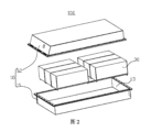
いくつかの実施例において、図4に示すように、図4は、本出願のいくつかの実施例による電池セル20の分解図である。電池セル20は、ケース21と、電極アセンブリ22と、エンドキャップ23とを含んでもよい。ケース21は、開口を有し、電極アセンブリ22は、ケース21内に収容され、エンドキャップ23は、開口にキャッピングするためのものである。
In some embodiments, as shown in FIG. 4, FIG. 4 is an exploded view of a
ケース21は、様々な形状、例えば、円柱体、長方体などであってもよい。ケース21の形状は、電極アセンブリ22の具体的な形状に基づいて確定することができる。例えば、電極アセンブリ22が円柱体構造であれば、ケース21は円柱体構造を選択してもよく、電極アセンブリ22が長方体構造であれば、ケース21は長方体構造を選択してもよい。
The
例示的に、図4において、ケース21は、一端が開放する中空長方体構造である。
For example, in FIG. 4, the
ケース21の材質は、種々のものが可能であり、例えば、銅、鉄、アルミニウム、ステンレススチール、アルミニウム合金などであってもよく、本出願の実施例では特にこれについて限定しない。
The
説明すべきこととして、ケース21内の電極アセンブリ22は、一つ又は複数であってもよい。例示的に、ケース21内の電極アセンブリ22は二つであり、二つの電極アセンブリ22は、積層して配置される。
It should be noted that the
いくつかの実施例において、電極アセンブリ22は、タブ221を含み、電極アセンブリ22のタブ221は、正極タブ221aと負極タブ221bに分けられる。
In some embodiments, the
電池セル20には積層して配置される二つの電極アセンブリ22が含まれる場合、一つの電極アセンブリ22の正極タブ221aと別の電極アセンブリ22の正極タブ221aは、二つの電極アセンブリ22の積層方向で対向して設置され、一つの電極アセンブリ22の負極タブ221bと別の電極アセンブリ22の負極タブ221bは、二つの電極アセンブリ22の積層方向で対向して設置されてもよい。
When the
いくつかの実施例において、電極アセンブリ22は、正極板と、負極板と、セパレータとをさらに含んでもよい。
In some embodiments, the
電極アセンブリ22は、正極板、セパレータ及び負極板を巻き取ることで形成される巻き取り型構造であってもよい。電極アセンブリ22は、正極板、セパレータ及び負極板を積層して配置することで形成される積層式構造であってもよい。
The
正極板は、正極集電体と、正極集電体の対向する両側に塗布される正極活物質層とを含む。負極板は、負極集電体と、負極集電体の対向する両側に塗布される負極活物質層とを含む。正極板において、正極集電体の正極活物質層が塗布されていない部分は、正極タブ221aとすることができ、負極板において、負極集電体の負極活物質層が塗布されていない部分は、負極タブ221bとすることができる。
The positive electrode plate includes a positive electrode collector and a positive electrode active material layer applied to both opposing sides of the positive electrode collector. The negative electrode plate includes a negative electrode collector and a negative electrode active material layer applied to both opposing sides of the negative electrode collector. In the positive electrode plate, the portion of the positive electrode collector that is not coated with the positive electrode active material layer can be a
セパレータには、電解質イオンが自由に通過することを確保するために、貫通する微細孔が大量設けられている。セパレータの材質は、PP(polypropylene、ポリプロピレン)又はPE(polyethylene、ポリエチレン)などであってもよい。 The separator has a large number of micro-pores that penetrate it to ensure that electrolyte ions can pass through it freely. The separator material may be PP (polypropylene) or PE (polyethylene), etc.
いくつかの実施例において、エンドキャップアセンブリ23は、エンドキャップ231と電極端子233とを含んでもよい。エンドキャップ231は、電極アセンブリ22を収容するための密閉空間24を形成するために、ケースの開口にキャッピングするように構成される。電極端子233は、エンドキャップ231に取り付けられ、電極端子233は、タブ221と電気的に接続するためのものであり、電極端子233は、電池セル20の電気エネルギーを出力するためのものである。
In some embodiments, the
ここで、密閉空間24は、さらに、流体媒体、例えば、電解液を収容するためのものである。
Here, the sealed
電極端子233は、正極電極端子233aと負極電極端子233bに分けられてもよく、正極電極端子233aは、正極タブ221aと電気的に接続するためのものであり、負極電極端子233bは、負極タブ221bと電気的に接続するためのものである。
The
例示的に、正極電極端子233aと負極電極端子233bは、エンドキャップ231の長手方向Xで間隔を置いて分布する。
Exemplarily, the positive electrode terminal 233a and the
いくつかの実施例において、エンドキャップアセンブリ23は、放圧手段234をさらに含んでもよく、放圧手段234はエンドキャップ231に取り付けられる。放圧手段234は、電池セル20の内部圧力又は温度が閾値に達した時、電池セル20内部の圧力を逃すためのものである。
In some embodiments, the
例示的に、エンドキャップ231の長手方向Xにおいて、放圧手段234は、正極電極端子233aと負極電極端子233bとの間に位置する。放圧手段234は、例えば、防爆弁、防爆シート、空気弁、放圧弁、安全弁などの部材であってもよい。
For example, in the longitudinal direction X of the
いくつかの実施例において、図5に示すように、図5は、本出願のいくつかの実施例による電池セル20の局部断面図であり、エンドキャップアセンブリ23は、エンドキャップ231と絶縁部材232とを含んでもよく、絶縁部材232は、エンドキャップ231と電極アセンブリ22を仕切るために、エンドキャップ231の厚さ方向Zで電極アセンブリ22に対向する側に設置されるように構成される。
In some embodiments, as shown in FIG. 5, which is a local cross-sectional view of a
ここで、エンドキャップ231には注入孔2311が設置されており、注入孔2311は、エンドキャップ231の厚さ方向Zでエンドキャップ231を貫通する。注入孔2311を通過して電池セル20の内部(密閉空間24)内に流体媒体を注入することができる。
Here, an
絶縁部材232には貫通孔2321が設置されており、貫通孔2321は、エンドキャップ231の厚さ方向Zで絶縁部材232を貫通する。注入孔2311を通過して電池セル20の内部に流体媒体を注入する時、流体媒体は、貫通孔2321を流れる。
The insulating
絶縁部材232は、絶縁材質であり、それはゴム、プラスチックなどの材質で製造されてもよく、プラスチックは、PBT(Polybutylene terephthalate、ポリブチレンテレフタレート)、PET(Polyethylene terephthalate、ポリエチレンテレフタレート)、PA(Polyamide、ポリアミド)などであってもよい。
The insulating
いくつかの実施例において、エンドキャップアセンブリ23は、ストッパ部材235をさらに含んでもよく、ストッパ部材235には排液口2351が設置されており、ストッパ部材235は、注入孔2311と貫通孔2321を経由した流体媒体を、流れ方向を変えた後に排液口2351を通過して電池セル20の内部に入らせるように構成される。
In some embodiments, the
ストッパ部材235は、流体媒体の流れ方向を変える役割を果たし、注入孔2311を通過して電池セル20の内部に流体媒体を注入する場合、流体媒体がエンドキャップ231における注入孔2311と絶縁部材232における貫通孔2321を経由した後、流体媒体は、ストッパ部材235のストッパ作用で方向を変え、且つストッパ部材235の排液口2351から電池セル20の内部に入り、流体媒体による電池セル20の内部の電極アセンブリ22のセパレータへの衝撃力を減少させ、電極アセンブリ22の正極板と負極板が互いに接触して短絡を引き起こすリスクを低減した。
The
いくつかの実施例において、エンドキャップアセンブリ23は、仕切り部材236をさらに含んでもよく、仕切り部材236は、タブ221が貫通孔2321を通ってエンドキャップ231と接触することを阻止するために、タブ221とエンドキャップ231を仕切るように構成される。
In some embodiments, the
仕切り部材236は、タブ221が絶縁部材232における貫通孔2321を貫通してエンドキャップ231と接触することを阻止するために、タブ221とエンドキャップ231を仕切る役割を果たし、タブ221とエンドキャップ231との接触による短絡のリスクを低減した。
The
ここで、エンドキャップ231の厚さ方向Zで、仕切り部材236は、タブ221とエンドキャップ231を仕切る役割を果たすために、少なくとも一部がエンドキャップ231とタブ221との間に位置する。
Here, in the thickness direction Z of the
説明すべきこととして、仕切り部材236は、正極タブ221a(図4に示す)とエンドキャップ231を仕切る役割を果たしてもよいし、負極タブ221b(図4に示す)とエンドキャップ231を仕切る役割を果たしてもよく、無論、正極タブ221aとエンドキャップ231を仕切る役割を果たし、また負極タブ221bとエンドキャップ231を仕切る役割を果たしてもよい。
It should be noted that the
いくつかの実施例において、仕切り部材236は、排液口2351よりもエンドキャップ231に近く、それによって仕切り部材236がタブ221とエンドキャップ231との仕切りをした後、流体媒体が排液口2351を通過して電池セル20の内部に入ることを容易にする。
In some embodiments, the
いくつかの実施例において、エンドキャップ231において、注入孔2311に対応する位置には突出部2312が形成されており、それによってエンドキャップ231の注入孔2311が設置されている位置の強度を増大させる。
In some embodiments, the
ここで、突出部2312は、少なくとも一部が貫通孔2321内に収容される。このような構造は、絶縁部材232とエンドキャップ231との全体的構造をよりコンパクトにし、電極アセンブリ22の空間をさらに広げ、電池セル20の容量の向上に有利である。
Here, at least a portion of the
例示的に、注入孔2311と貫通孔2321は同軸に設置され、貫通孔2321の孔は、注入孔2311の孔径より大きい。
For example, the
図6に示すように、図6は、図5に示すエンドキャップアセンブリ23の部分分解図であり、エンドキャップ231は、その厚さ方向Zで対向して設置される第1の内面2313と第1の外面2314を有し、突出部2312は第1の内面2313に突設され、突出部2312は、第1の外面2314と反対側の第1の端面2312aを有し、注入孔2311の両端は、それぞれ第1の端面2312aと第1の外面2314を貫通する。
As shown in FIG. 6, FIG. 6 is a partial exploded view of the
絶縁部材232は、エンドキャップ231の厚さ方向Zで対向して設置される第2の内面2322と第2の外面2323を有し、貫通孔2321の両端はそれぞれ第2の内面2322と第2の外面2323を貫通する。
The insulating
説明すべきこととして、絶縁部材232の第2の外面2323はエンドキャップ231の第1の内面2313に貼り合わせてもよく、絶縁部材232の第2の外面2323とエンドキャップ231の第1の内面2313は距離を置いて配置されてもよい。絶縁部材232の第2の外面2323がエンドキャップ231の第1の内面2313に貼り合わせ、且つ突出部2312のエンドキャップ231の厚さ方向Zでのサイズが貫通孔2321のエンドキャップ231の厚さ方向Zでのサイズより小さい場合、突出部2312を貫通孔2321内に完全に収容することができる。絶縁部材232の第2の外面2323とエンドキャップ231の第1の内面2313が距離を置いて配置される場合、突出部2312を貫通孔2321内に部分的に収容することができる。
It should be noted that the second
いくつかの実施例において、図7に示すように、図7は、図5に示す電池セル20のA箇所の局部拡大図であり、エンドキャップ231の厚さ方向Zでは、突出部2312のエンドキャップ231への投影と仕切り部材236のエンドキャップ231への投影は、少なくとも部分的に重なる。つまり、エンドキャップ231の厚さ方向Zでは、突出部2312のエンドキャップ231への投影と仕切り部材236のエンドキャップ231への投影は部分的に重なり、それによって仕切り部材236は、タブ221と突出部2312に対して良好な仕切り役割を果たす。
In some embodiments, as shown in FIG. 7, which is a local enlarged view of a portion A of the
例示的に、エンドキャップ231の厚さ方向Zでは、突出部2312のエンドキャップ231への投影、仕切り部材236のエンドキャップ231への投影及びタブ221のエンドキャップ231への投影の三者は、少なくとも部分的に重なる。
For example, in the thickness direction Z of the
いくつかの実施例において、電池セル20は、集電部材25をさらに含んでもよく、集電部材25は、接続タブ221と電極端子233を接続することで電極端子233とタブ221との電気的接続を実現するためのものである。理解できるように、正極電極端子233a(図4に示す)と正極タブ221a(図4に示す)は一つの集電部材25によって電気的に接続されてもよく、負極電極端子233b(図4に示す)と負極タブ221b(図4に示す)は別の集電部材25によって電気的に接続されてもよい。
In some embodiments, the
例示的に、集電部材25は、金属導体、例えば、銅、鉄、アルミニウム、ステンレススチール、アルミニウム合金などであってもよい。集電部材25は電極端子233に溶接されてもよく、タブ221は集電部材25に溶接されてもよい。
Exemplarily, the current collecting
いくつかの実施例において、集電部材25は、エンドキャップ231と反対側の接続面251を含んでもよく、接続面251は、タブ221に接続されるように構成される。エンドキャップ231の厚さ方向Zでは、接続面251は、仕切り部材236よりもエンドキャップ231から離れる。このような構造は、タブ221とエンドキャップ231との間の距離を増大させ、タブ221がエンドキャップ231と接触するリスクをさらに低減することができる。
In some embodiments, the current collecting
本実施例において、エンドキャップ231の厚さ方向Zでは、タブ221と集電部材25は積層して配置され、集電部材25は、タブ221よりも絶縁部材232に近い。
In this embodiment, in the thickness direction Z of the
例示的に、タブ221は、集電部材25の接続面251に溶接されてもよい。
For example, the
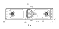
いくつかの実施例において、図8に示すように、図8は、図5に示すエンドキャップアセンブリ23の底面図であり、集電部材25には、ストッパ部材235と仕切り部材236を回避する回避開口252が設置されている。
In some embodiments, as shown in FIG. 8, which is a bottom view of the
いくつかの実施例において、図9と図10に示すように、図9は、図5に示す絶縁部材232の局部断面図であり、図10は、図5に示す絶縁部材232、ストッパ部材235及び仕切り部材236の接続概略図であり、エンドキャップ231の厚さ方向Zでは、ストッパ部材235の絶縁部材232への投影は、貫通孔2321の一部を覆う。このような構造によって、ストッパ部材235は、注入孔2311と貫通孔2321を流れる流体媒体に対して良好なストッパ作用を果たし、それによって流体媒体の流れ方向を変えるという目的を達成する。
In some embodiments, as shown in Figures 9 and 10, Figure 9 is a local cross-sectional view of the insulating
いくつかの実施例において、ストッパ部材235は、絶縁部材232に接続されて、ストッパ部材235と絶縁部材232との相対的位置を一定に維持するように構成され、ストッパ部材235が注入孔2311と貫通孔2321を流れる流体媒体の流れ方向を変えることに有利である。
In some embodiments, the
ストッパ部材235と絶縁部材232の両方は、例えば、接着、熱融着接続、一体成形などのように固定接続されてもよいし、ストッパ部材235と絶縁部材232の両方は、例えば、スナップフィット、螺着などのように取り外し可能に接続されてもよい。
The
例示的に、ストッパ部材235は、絶縁部材232の第2の内面2322に直接固定されている。
Illustratively, the
いくつかの実施例において、ストッパ部材235は、接続部2352とストッパ部2353とを含み、接続部2352は、ストッパ部2353と絶縁部材232を接続するように構成され、ストッパ部2353は、エンドキャップ231の厚さ方向Zにおいて貫通孔2321と対向して設置され、排液口2351は接続部2352に設置されている。
In some embodiments, the
接続部2352は、ストッパ部2353と絶縁部材232を接続する役割を果たす。ストッパ部2353がエンドキャップ231の厚さ方向Zにおいて貫通孔2321と対向して設置されるため、ストッパ部2353は、流体媒体に対して良好なストッパ作用を果たし、それによって流体媒体が流れ方向を変え且つ排液口2351から電池セル20内に入る。
The
例示的に、接続部2352は、エンドキャップ231の厚さ方向Zにおける両端が開放する中空構造であってもよく、接続部2352の内部に貫通孔2321と排液口2351を連通する流路が形成され、接続部2352は、エンドキャップ231の厚さ方向Zにおける一端が絶縁部材232の第2の内面2322に接続され、ストッパ部2353は、接続部2352のエンドキャップ231の厚さ方向Zにおける他端に閉塞される。
For example, the
いくつかの実施例において、図11に示すように、図11は、本出願の別のいくつかの実施例による絶縁部材232の局部断面図であり、ストッパ部2353の内面にガイド斜面2353aが形成されてもよく、ガイド斜面2353aの低い端は排液口2351の下縁部に接続され、ガイド斜面2353aは、接続部2352の内部に入った流体媒体を排液口2351にガイドし、流体媒体がストッパ部材235の内部に残留するリスクを低減するためのものである。ここで言う下縁部は、排液口2351の絶縁部材232から離れる側の縁部である。
In some embodiments, as shown in FIG. 11, which is a local cross-sectional view of an insulating
ガイド斜面2353aは、傾斜平面であってもよいし、テーパ面であってもよく、テーパ面は、円錐面であってもよいし、角錐面であってもよい。例えば、接続部2352には一つのみの排液口2351が設置されている場合、ガイド斜面2353aは、一端が高く他端が低い傾斜平面であってもよい。さらに例えば、接続部2352には複数の排液口2351が間隔を置いて周方向に配置され、ガイド斜面2353aは、中央が高く周囲が低いテーパ面であってもよい。
The
例示的に、図11において、接続部2352には対向して配置される二つの排液口2351が設置され、ガイド斜面2353aは、中央が高く周囲が低いテーパ面である。
For example, in FIG. 11, the
説明すべきこととして、他の実施例において、ストッパ部材235は、エンドキャップ231ではなく、電池セル20における他の部材に接続されてもよく、例えば、ストッパ部材235は、エンドキャップ231に接続される。
It should be noted that in other embodiments, the
いくつかの実施例において、引き続き図9と図10に示すように、エンドキャップ231の厚さ方向Zでは、仕切り部材236の絶縁部材232への投影は貫通孔2321一部を覆う。仕切り部材236は、注入孔2311と貫通孔2321を流れる流体媒体に対してストッパ作用を果たし、流体媒体による電極アセンブリ22のセパレータへの衝撃力を低減することができる。
In some embodiments, as still shown in Figures 9 and 10, in the thickness direction Z of the
例示的に、エンドキャップ231の厚さ方向Zでは、仕切り部材236の絶縁部材232への投影とストッパ部材235の絶縁部材232への投影とはずれており、即ち仕切り部材236の絶縁部材232への投影とストッパ部材235の絶縁部材232への投影とは重ならず、仕切り部材236と絶縁部材232との全体的構造を簡略化することができる。
For example, in the thickness direction Z of the
説明すべきこととして、エンドキャップ231の厚さ方向Zでは、仕切り部材236の絶縁部材232への投影とストッパ部材235の絶縁部材232への投影とがちょうど交差する場合も、仕切り部材236の絶縁部材232への投影とストッパ部材235の絶縁部材232への投影とがずれている場合に属する。
It should be noted that in the thickness direction Z of the
いくつかの実施例において、仕切り部材236は、ストッパ部材235に接続されるように構成され、それによって仕切り部材236とストッパ部材235との全体性をより高くし、ストッパ部材235と仕切り部材236との全体的構造をよりコンパクトにする。
In some embodiments, the
説明すべきこととして、仕切り部材236とストッパ部材235の両方は、例えば、接着、熱融着接続、一体成形などのように固定接続されてもよいし、仕切り部材236とストッパ部材235の両方は、例えば、スナップフィット、螺着などのように取り外し可能に接続されてもよい。
It should be noted that both the
仕切り部材236がストッパ部材235に接続される場合、仕切り部材236と絶縁部材232の両方は、接続されてもよいし、一定の距離離れてもよい。
When the
例示的に、図9と図10において、仕切り部材236はストッパ部材235に接続され、且つ仕切り部材236は絶縁部材232の第2の内面2322に接続される。
Illustratively, in Figures 9 and 10, the
いくつかの実施例において、ストッパ部材235、仕切り部材236、絶縁部材232は、一体成形構造であり、即ちストッパ部材235、仕切り部材236と絶縁部材232の三者が一体成形され、それによって三者の成形プロセスを簡略化し、三者の堅牢性を向上させる。
In some embodiments, the
他の実施例において、仕切り部材236は、ストッパ部材235に接続されず、絶縁部材232のみに接続されてもよく、仕切り部材236は、絶縁部材232とストッパ部材235のいずれにも接続されなくてもよいが、仕切り部材236は、電池セル20の他の部材に接続されてもよく、例えば、仕切り部材236は、中間部材を介してケース21に接続され、それによってタブ221とエンドキャップ231を仕切ることができる位置に仕切り部材236を固定する。
In other embodiments, the
いくつかの実施例において、ストッパ部材235の第1の方向Yにおける少なくとも一方側には仕切り部材236が設置されており、第1の方向Yは厚さ方向Zに垂直である。つまり、ストッパ部材235の第1の方向Yにおける一方側には仕切り部材236が設置されていてもよいし、ストッパ部材235の第1の方向Yにおける両側にはいずれも仕切り部材236が設置されていてもよい。
In some embodiments, a
説明すべきこととして、本実施例において、特に上記第1の方向Yについて限定せず、例えば、第1の方向Yは、エンドキャップ231の長手方向Xであってもよいし、エンドキャップ231の幅方向であってもよい。
It should be noted that in this embodiment, there is no particular limitation on the first direction Y, and for example, the first direction Y may be the longitudinal direction X of the
いくつかの実施例において、図12に示すように、図12は、図5に示す絶縁部材232、集電部材25及びタブ221の位置関係図であり、第1の方向Yでは、ストッパ部材235の少なくとも一方側には排液口2351が設置されており、タブ221は、ストッパ部材235の一方側に配置され、且つ排液口2351と対向するように構成される。つまり、ストッパ部材235の第1の方向Yにおける一方側には排液口2351が設置されていてもよいし、ストッパ部材235の第1の方向Yにおける両側にはいずれも排液口2351が設置されていてもよい。
In some embodiments, as shown in FIG. 12, which is a positional relationship diagram of the insulating
ストッパ部材235の第1の方向Yにおける少なくとも一方側には排液口2351が設置されているため、タブ221がストッパ部材235の第1の方向Yにおける一方側に配置され且つ排液口2351と対向すると、仕切り部材236は、タブ221とエンドキャップ231を仕切ることができる。
Since a
ここで、ストッパ部材235は、第1の側面2354を含んでもよく、仕切り部材236と排液口2351は、いずれも第1の側面2354に設置されている。仕切り部材236は、ストッパ部材235と反対側の第2の側面2361を含んでもよく、第2の側面2361は、第1の側面2354と平行して設置される。このような構造は、仕切り部材236が占有する他の部材(例えば、集電部材25とタブ221)の空間を減少させることができる。
Here, the
ここで、第1の側面2354と第2の側面2361は、いずれも平面であってもよい。
Here, the
例示的に、第1の方向Yは、エンドキャップ231の幅方向と一致する。
For example, the first direction Y coincides with the width direction of the
いくつかの実施例において、ストッパ部材235の第1の方向Yにおける両側には、いずれも仕切り部材236が設置されている。
In some embodiments, a
ストッパ部材235の第1の方向Yにおける両側にはいずれも仕切り部材236が設けられているため、ストッパ部材235における二つの仕切り部材236は、第1の方向Yにおける二つのタブ221をエンドキャップ231と仕切ることができる。
Since
電池セル20が二つの電極アセンブリ22(図5に示す)を含み、仕切り部材236がエンドキャップ231(図5に示す)と電極アセンブリ22の正極タブ221a(図5に示す)を仕切るためのものであることを例とする。二つの電極アセンブリ22は、第1の方向Yに沿って積層して配置され、一つの電極アセンブリ22の正極タブ221aと別の電極アセンブリ22の正極タブ221aが、第1の方向Yで対向して設置され、一つの電極アセンブリ22の負極タブ221bと別の電極アセンブリ22の負極タブ221bが、第1の方向Yで対向して設置される。ストッパ部材235の第1の方向Yにおける一側に位置する仕切り部材236は、エンドキャップ231と一つの電極アセンブリ22の正極タブ221aを仕切るためのものであってもよく、ストッパ部材235の第1の方向Yにおける他側に位置する仕切り部材236は、エンドキャップ231と別の電極アセンブリ22の正極タブ221aを仕切るためのものであってもよい。
For example, the
本実施例において、ストッパ部材235は、第1の方向Yで対向して配置される二つの第1の側面2354を有してもよく、二つの第1の側面2354には、いずれも排液口2351が設置されてもよい。
In this embodiment, the
例示的に、第1の方向Yはエンドキャップ231の幅方向と一致し、二つの第1の側面2354の第1の方向Yでの距離は、ストッパ部材235のエンドキャップ231の長手方向X(図11に示す)でのサイズより小さく、それによって第1の側面2354にサイズがより大きい排液口2351を開設することを容易にする。
Illustratively, the first direction Y coincides with the width direction of the
いくつかの実施例において、図12を引き続き参照されたく、第1の方向Yでは、仕切り部材236がストッパ部材235から離れる方向に沿って、貫通孔2321の壁の一部は、仕切り部材236よりもはみ出している。即ち仕切り部材236は、そのストッパ部材235から離れる方向に沿って貫通孔2321を完全にはみ出しておらず、このような構造は、仕切り部材236が占有する空間を減少させ、集電部材25と仕切り部材236に干渉が発生するリスクを低減することができる。
In some embodiments, with continued reference to FIG. 12, in the first direction Y, a portion of the wall of the through
理解できるように、第1の方向Yでは、貫通孔2321の壁の一部は、仕切り部材236がストッパ部材235から離れる方向に沿って、仕切り部材236の第2の側面2361よりもはみ出している。
As can be seen, in the first direction Y, a portion of the wall of the through
例示的に、仕切り部材236がストッパ部材から離れる方向に沿って、貫通孔2321は、仕切り部材236よりもはみ出しているはみ出し部分2321aを有し、集電部材25の厚さ方向への投影は、はみ出し部分2321aを少なくとも部分的に覆う。このような設置によって、集電部材25とタブ221との十分な接続面積を確保することができる。例えば、集電部材25がタブ221に溶接接続され、集電部材25の厚さ方向への投影がはみ出し部分2321aを少なくとも部分的に覆い、集電部材25とタブ221との十分な溶接面積を確保することができる。
For example, the through
いくつかの実施例において、図13に示すように、図13は、本出願のさらなるいくつかの実施例による電池セル20の局部拡大図であり、エンドキャップアセンブリ23は、閉塞部材237をさらに含んでもよく、閉塞部材237は、エンドキャップ231の注入孔2311内に挿設されて、注入孔2311を閉塞するためのものである。ストッパ部材235は、閉塞部材237がエンドキャップ231の厚さ方向Zにおいてストッパ部材235に当接する場合に、閉塞部材237の電池セル20の内部への移動を制限するように構成される。
In some embodiments, as shown in FIG. 13, which is a partially enlarged view of a
ストッパ部材235は、閉塞部材237に対してストッパ作用を果たすことができ、ストッパ部材235が電池セル20の内部に落ちるリスクを低減する。
The
例示的に、閉塞部材237は、ゴム、プラスチックなどの材質のシールネイルであってもよい。
For example, the blocking
いくつかの実施例において、ストッパ部材235は、エンドキャップ231の厚さ方向Zにおいて注入孔2311と対向するストッパ面2355を含む。エンドキャップ231は、エンドキャップ231の厚さ方向Zにおいてストッパ面2355と対向する第1の表面2315を有する。閉塞部材237のエンドキャップ231の厚さ方向Zでの長さは、第1の表面2315とストッパ面2355との間の距離より大きい。このような構造は、ストッパ部材235が注入孔2311から脱離して第1の表面2315とストッパ面2355との隙間内に入って、閉塞部材237が注入孔2311を閉塞して失効を引き起こすリスクを低減した。
In some embodiments, the
本実施例において、第1の表面2315は突出部2312の第1の端面2312a(図6に示す)である。他の実施例において、エンドキャップ231の第1の内面2313(図6に示す)には突出部2312が設置されていない場合、第1の表面2315は、エンドキャップ231の第1の内面2313であってもよい。
In this embodiment, the
図14に示すように、図14は、本出願のいくつかの実施例による電池セル20の製造方法のフローチャートであり、電池セル20の製造方法は、
開口を有するケース21を提供するS100と、
タブ221を含む電極アセンブリ22を提供するS200と、
エンドキャップアセンブリ23を提供するS300と、
電極アセンブリ22をケース21内に収容するS400と、
エンドキャップアセンブリ23をケース21の開口にキャッピングするS500とを含む。
As shown in FIG. 14 , FIG. 14 is a flowchart of a method for manufacturing a
S100: providing a
providing an
S300 providing an
S400: housing the
and S500 for capping the opening of the
ここで、エンドキャップアセンブリ23は、エンドキャップ231と、絶縁部材232と、ストッパ部材235と、仕切り部材236とを含む。エンドキャップ231には注入孔2311が設置されており、注入孔2311は、エンドキャップ231の厚さ方向Zでエンドキャップ231を貫通し、エンドキャップ231は、ケース21の開口にキャッピングするためのものである。絶縁部材232は、エンドキャップ231の厚さ方向Zにおける一方側に設けられるように構成され、絶縁部材232には貫通孔2321が設置されており、貫通孔2321は厚さ方向Zで絶縁部材232を貫通する。ストッパ部材235には排液口2351が設置されており、ストッパ部材235は、注入孔2311と貫通孔2321を経由した流体媒体を、流れ方向を変えた後に排液口2351を通過して電池セル20の内部に入らせるように構成される。仕切り部材236は、タブ221が貫通孔2321を通ってエンドキャップ231と接触することを阻止するために、タブ221とエンドキャップ231を仕切るように構成される。
Here, the
説明すべきこととして、上記電池セル20の製造方法に基づいて電池セル20を組み立てる場合、ステップS100、S200とS300を実行する順序について限定せず、例えば、まずステップS300を実行し、次にステップS200を実行し、次にステップS100を実行してもよい。
It should be noted that when assembling a
上記電池セル20の製造方法によって製造される電池セル20の関連構造は、上記各実施例による電池セル20を参照することができる。
For the related structure of the
図15に示すように、図15は、本出願のいくつかの実施例による電池セル20の製造機器2000の例示的ブロック図であり、製造機器2000は、第1の提供装置1100と、第2の提供装置1200と、第3の提供装置1300と、組み立て装置1400とを含む。
As shown in FIG. 15, FIG. 15 is an exemplary block diagram of a
第1の提供装置1100は、開口を有するケース21を提供するためのものである。第2の提供装置1200は、タブ221を含む電極アセンブリ22を提供するためのものである。第3の提供装置1300は、エンドキャップアセンブリ23を提供するためのものである。組み立て装置1400は、電極アセンブリ22ケース21内に収容するためのものであり、さらにエンドキャップアセンブリ23をケース21の開口にキャッピングするためのものである。
The first providing
エンドキャップアセンブリ23は、エンドキャップ231と、絶縁部材232と、ストッパ部材235と、仕切り部材236とを含む。エンドキャップ231には注入孔2311が設置されており、注入孔2311は、エンドキャップ231の厚さ方向Zでエンドキャップ231を貫通し、エンドキャップ231は、ケース21の開口にキャッピングするためのものである。絶縁部材232は、エンドキャップ231の厚さ方向Zにおける一方側に設けられるように構成され、絶縁部材232には貫通孔2321が設置されており、貫通孔2321は厚さ方向Zで絶縁部材232を貫通する。ストッパ部材235には排液口2351が設置されており、ストッパ部材235は、注入孔2311と貫通孔2321を経由した流体媒体を、流れ方向を変えた後に排液口2351を通過して電池セル20の内部に入らせるように構成される。仕切り部材236は、タブ221が貫通孔2321を通ってエンドキャップ231と接触することを阻止するために、タブ221とエンドキャップ231を仕切るように構成される。
The
上記電池セル20の製造機器2000によって製造される電池セル20の関連構造は、上記各実施例による電池セル20を参照することができる。
The relevant structure of the
説明すべきこととして、衝突しない場合、本出願における実施例及び実施例における特徴は互いに組み合わせることができる。 It should be noted that, where there is no conflict, the embodiments and features of the embodiments in this application may be combined with each other.
以上の実施例は、本出願の技術案を説明するためのものに過ぎず、本出願を限定するためのものではなく、当業者にとって、本出願には、様々な修正及び変更が可能である。本出願の精神及び原則内で行われる全ての修正、同等の置き換え、改善などは、いずれも本出願の保護範囲内に含まれるべきである。 The above examples are merely intended to explain the technical solution of the present application, and are not intended to limit the present application. Those skilled in the art may make various modifications and changes to the present application. All modifications, equivalent replacements, improvements, etc. made within the spirit and principles of the present application should be included within the scope of protection of the present application.
10-筐体
11-第1の部分
12-第2の部分
13-収容空間
20-電池セル
21-ケース
22-電極アセンブリ
221-タブ
221a-正極タブ
221b-負極タブ
23-エンドキャップアセンブリ
231-エンドキャップ
2311-注入孔
2312-突出部
2312a-第1の端面
2313-第1の内面
2314-第1の外面
2315-第1の表面
232-絶縁部材
2321-貫通孔
2322-第2の内面
2323-第2の外面
233-電極端子
233a-正極電極端子
233b-負極電極端子
234-放圧手段
235-ストッパ部材
2351-排液口
2352-接続部
2353-ストッパ部
2353a-ガイド斜面
2354-第1の側面
2355-ストッパ面
236-仕切り部材
2361-第2の側面
237-閉塞部材
24-密閉空間
25-集電部材
251-接続面
252-回避開口
30-電池モジュール
40-バスバー部材
100-電池
200-コントローラ
300-モータ
1000-車両
1100-第1の提供装置
1200-第2の提供装置
1300-第3の提供装置
1400-組み立て装置
2000-製造機器
X-長手方向
Y-第1の方向
Z-厚さ方向
10-Housing 11-First Part 12-Second Part 13-Accommodating Space 20-Battery Cell 21-Case 22-Electrode Assembly 221-
Claims (22)
注入孔が設置されるエンドキャップであって、前記注入孔は前記エンドキャップの厚さ方向において前記エンドキャップを貫通するエンドキャップと、
前記エンドキャップの前記厚さ方向における一方側に設けられるように構成される絶縁部材であって、前記絶縁部材には貫通孔が設置されており、前記貫通孔は前記厚さ方向において前記絶縁部材を貫通する絶縁部材と、
排液口が設置されており、前記注入孔と前記貫通孔を経由した流体媒体を、流れ方向を変えた後に前記排液口を通過して前記電池セルの内部に入らせるように構成されるストッパ部材と、
前記タブが前記貫通孔を貫通して前記エンドキャップと接触することを阻止するために、前記タブと前記エンドキャップを仕切るように構成される仕切り部材とを含み、
前記ストッパ部材の第1の方向における少なくとも一方側には前記仕切り部材が設置されており、前記第1の方向は前記厚さ方向に垂直であり、
前記第1の方向に、前記仕切り部材が前記ストッパ部材から離れる方向に沿って、前記貫通孔の壁の一部は、前記仕切り部材よりもはみ出している、ことを特徴とするエンドキャップアセンブリ。 1. An end cap assembly for use with a battery cell including an electrode assembly having a tab, comprising:
an end cap having an injection hole disposed therein, the injection hole penetrating the end cap in a thickness direction of the end cap;
an insulating member configured to be provided on one side of the end cap in the thickness direction, the insulating member having a through hole formed therein, the through hole penetrating the insulating member in the thickness direction;
a stopper member having a drainage port provided therein, configured to allow the fluid medium passing through the injection hole and the through hole to pass through the drainage port and enter the inside of the battery cell after changing its flow direction;
a partition member configured to separate the tab from the end cap to prevent the tab from passing through the through hole and contacting the end cap ,
the partition member is provided on at least one side of the stopper member in a first direction, the first direction being perpendicular to the thickness direction;
an end cap assembly comprising: a first portion of a wall of the through hole extending beyond the partition member along a direction in which the partition member moves away from the stopper member in the first direction ;
前記電池セルは集電部材をさらに含み、前記集電部材は、タブと前記エンドキャップに取り付けられる電極端子とを接続するためのものであり、前記集電部材の前記厚さ方向への投影は、前記はみ出し部分を少なくとも部分的に覆う、ことを特徴とする請求項1~7のいずれか一項に記載のエンドキャップアセンブリ。 the through hole has a protruding portion protruding beyond the partition member along a direction in which the partition member moves away from the stopper member,
The end cap assembly according to any one of claims 1 to 7, characterized in that the battery cell further includes a current collecting member for connecting a tab and an electrode terminal attached to the end cap, and a projection of the current collecting member in the thickness direction at least partially covers the protruding portion.
前記ストッパ部材は、前記閉塞部材が前記厚さ方向に沿って前記ストッパ部材に当接するときに、前記閉塞部材の前記電池セルの内部への移動を制限するように構成される、ことを特徴とする請求項1~16のいずれか一項に記載のエンドキャップアセンブリ。 the end cap assembly further includes a closing member inserted into the injection hole to close the injection hole,
The end cap assembly of any one of claims 1 to 16, characterized in that the stopper member is configured to limit movement of the blocking member into the inside of the battery cell when the blocking member abuts against the stopper member along the thickness direction.
前記エンドキャップは、前記厚さ方向において前記ストッパ面と対向する第1の表面を有し、
前記閉塞部材の前記厚さ方向における長さは、前記第1の表面と前記ストッパ面との間の距離より大きい、ことを特徴とする請求項17に記載のエンドキャップアセンブリ。 the stopper member includes a stopper surface facing the injection hole in the thickness direction,
the end cap has a first surface facing the stopper surface in the thickness direction,
18. The end cap assembly of claim 17, wherein the length of the closure member in the thickness direction is greater than the distance between the first surface and the stop surface.
前記厚さ方向においては、前記接続面は、前記仕切り部材よりも前記エンドキャップから離れている、ことを特徴とする請求項1~18のいずれか一項に記載のエンドキャップアセンブリ。 the battery cell further includes a current collecting member for connecting the tab and an electrode terminal attached to the end cap, the current collecting member including a connection surface opposite to the end cap, the connection surface being configured to be connected to the tab;
The end cap assembly according to any one of claims 1 to 18, characterized in that, in the thickness direction, the connection surface is farther from the end cap than the partition member.
開口を有するケースと、
前記ケースに収容され、タブを含む電極アセンブリと、
前記開口にキャッピングするための、請求項1~19のいずれか一項に記載のエンドキャップアセンブリとを含む、ことを特徴とする電池セル。 A battery cell,
a case having an opening;
an electrode assembly housed in the case and including a tab;
and an end cap assembly according to any one of claims 1 to 19 for capping the opening.
筐体と、
前記筐体内に収容される、請求項20に記載の電池セルとを含む、ことを特徴とする電池。 A battery,
A housing and
and the battery cell of claim 20 contained within the housing.
Applications Claiming Priority (1)
| Application Number | Priority Date | Filing Date | Title |
|---|---|---|---|
| PCT/CN2021/085426 WO2022205463A1 (en) | 2021-04-02 | 2021-04-02 | End cover assembly, battery cell, battery, and method and device for manufacturing battery cell |
Publications (2)
| Publication Number | Publication Date |
|---|---|
| JP2023527512A JP2023527512A (en) | 2023-06-29 |
| JP7581372B2 true JP7581372B2 (en) | 2024-11-12 |
Family
ID=83448381
Family Applications (1)
| Application Number | Title | Priority Date | Filing Date |
|---|---|---|---|
| JP2022563184A Active JP7581372B2 (en) | 2021-04-02 | 2021-04-02 | End cap assembly, battery cell, battery and battery cell manufacturing method and apparatus |
Country Status (7)
| Country | Link |
|---|---|
| US (1) | US12261307B2 (en) |
| EP (1) | EP4089831B1 (en) |
| JP (1) | JP7581372B2 (en) |
| KR (1) | KR102869409B1 (en) |
| CN (1) | CN220731651U (en) |
| HU (1) | HUE065361T2 (en) |
| WO (1) | WO2022205463A1 (en) |
Families Citing this family (8)
| Publication number | Priority date | Publication date | Assignee | Title |
|---|---|---|---|---|
| JP7675691B2 (en) * | 2022-08-30 | 2025-05-13 | プライムプラネットエナジー&ソリューションズ株式会社 | Battery cell and manufacturing method thereof |
| CN118435451A (en) * | 2022-09-16 | 2024-08-02 | 宁德时代新能源科技股份有限公司 | Battery cells, batteries and electrical equipment |
| CN115579597B (en) * | 2022-11-11 | 2023-03-24 | 深圳海润新能源科技有限公司 | Energy storage device and electric equipment |
| WO2024098421A1 (en) * | 2022-11-11 | 2024-05-16 | 深圳海润新能源科技有限公司 | Energy storage apparatus and electric device |
| CN115863864B (en) * | 2023-02-09 | 2023-05-09 | 深圳海润新能源科技有限公司 | Lower plastic component, energy storage device and electric equipment |
| CN116345028B (en) * | 2023-03-31 | 2025-07-25 | 厦门海辰储能科技股份有限公司 | End cap assembly and battery cell |
| JP7819306B2 (en) * | 2023-09-01 | 2026-02-24 | 晶科▲儲▼能科技有限公司 | Cell Top Cover |
| KR20250077839A (en) * | 2023-11-24 | 2025-06-02 | 삼성에스디아이 주식회사 | Secondary battery |
Citations (8)
| Publication number | Priority date | Publication date | Assignee | Title |
|---|---|---|---|---|
| JP2013257951A (en) | 2012-06-11 | 2013-12-26 | Hitachi Vehicle Energy Ltd | Square secondary battery |
| JP2016207353A (en) | 2015-04-17 | 2016-12-08 | トヨタ自動車株式会社 | Secondary battery |
| CN207938663U (en) | 2018-01-31 | 2018-10-02 | 比亚迪股份有限公司 | Lid assemblies, cells, battery packs and vehicles |
| JP2018198163A (en) | 2017-05-24 | 2018-12-13 | トヨタ自動車株式会社 | Secondary battery |
| CN208478390U (en) | 2018-07-26 | 2019-02-05 | 宁德时代新能源科技股份有限公司 | Cap assembly and secondary cell |
| JP2019129129A (en) | 2018-01-26 | 2019-08-01 | 三洋電機株式会社 | Power storage device |
| WO2021024629A1 (en) | 2019-08-07 | 2021-02-11 | 三洋電機株式会社 | Battery |
| CN112421155A (en) | 2019-08-05 | 2021-02-26 | 比亚迪股份有限公司 | Battery and cover plate assembly thereof |
Family Cites Families (8)
| Publication number | Priority date | Publication date | Assignee | Title |
|---|---|---|---|---|
| KR101893954B1 (en) * | 2012-01-16 | 2018-08-31 | 삼성에스디아이 주식회사 | Secondary battery |
| KR20150017624A (en) * | 2013-08-07 | 2015-02-17 | 삼성에스디아이 주식회사 | Rechargeable battery |
| KR102623625B1 (en) * | 2016-04-26 | 2024-01-09 | 삼성에스디아이 주식회사 | Rechargeable battery having protection circuit module |
| KR102574485B1 (en) * | 2018-02-27 | 2023-09-01 | 삼성에스디아이 주식회사 | Rechargeable battery |
| CN210778796U (en) * | 2019-08-20 | 2020-06-16 | 比亚迪股份有限公司 | Battery, cover plate assembly and pole terminal thereof |
| HUE068271T2 (en) * | 2020-05-19 | 2024-12-28 | Contemporary Amperex Technology Hong Kong Ltd | End cover assembly, liquid injection method and device |
| CN116979196A (en) * | 2023-06-30 | 2023-10-31 | 广东省豪鹏新能源科技有限公司 | A cover assembly and a power battery having the cover assembly |
| CN117060021B (en) * | 2023-10-10 | 2024-01-26 | 厦门海辰储能科技股份有限公司 | Insulating part, end cover assembly, battery monomer and electric equipment |
-
2021
- 2021-04-02 JP JP2022563184A patent/JP7581372B2/en active Active
- 2021-04-02 WO PCT/CN2021/085426 patent/WO2022205463A1/en not_active Ceased
- 2021-04-02 EP EP21827163.3A patent/EP4089831B1/en active Active
- 2021-04-02 KR KR1020227035586A patent/KR102869409B1/en active Active
- 2021-04-02 HU HUE21827163A patent/HUE065361T2/en unknown
- 2021-04-02 CN CN202190000783.7U patent/CN220731651U/en active Active
- 2021-12-22 US US17/558,734 patent/US12261307B2/en active Active
Patent Citations (8)
| Publication number | Priority date | Publication date | Assignee | Title |
|---|---|---|---|---|
| JP2013257951A (en) | 2012-06-11 | 2013-12-26 | Hitachi Vehicle Energy Ltd | Square secondary battery |
| JP2016207353A (en) | 2015-04-17 | 2016-12-08 | トヨタ自動車株式会社 | Secondary battery |
| JP2018198163A (en) | 2017-05-24 | 2018-12-13 | トヨタ自動車株式会社 | Secondary battery |
| JP2019129129A (en) | 2018-01-26 | 2019-08-01 | 三洋電機株式会社 | Power storage device |
| CN207938663U (en) | 2018-01-31 | 2018-10-02 | 比亚迪股份有限公司 | Lid assemblies, cells, battery packs and vehicles |
| CN208478390U (en) | 2018-07-26 | 2019-02-05 | 宁德时代新能源科技股份有限公司 | Cap assembly and secondary cell |
| CN112421155A (en) | 2019-08-05 | 2021-02-26 | 比亚迪股份有限公司 | Battery and cover plate assembly thereof |
| WO2021024629A1 (en) | 2019-08-07 | 2021-02-11 | 三洋電機株式会社 | Battery |
Also Published As
| Publication number | Publication date |
|---|---|
| JP2023527512A (en) | 2023-06-29 |
| EP4089831B1 (en) | 2023-11-15 |
| US12261307B2 (en) | 2025-03-25 |
| KR102869409B1 (en) | 2025-10-14 |
| EP4089831A4 (en) | 2022-11-16 |
| US20220320642A1 (en) | 2022-10-06 |
| CN220731651U (en) | 2024-04-05 |
| EP4089831A1 (en) | 2022-11-16 |
| HUE065361T2 (en) | 2024-05-28 |
| EP4089831C0 (en) | 2023-11-15 |
| WO2022205463A1 (en) | 2022-10-06 |
| KR20220151694A (en) | 2022-11-15 |
Similar Documents
| Publication | Publication Date | Title |
|---|---|---|
| JP7581372B2 (en) | End cap assembly, battery cell, battery and battery cell manufacturing method and apparatus | |
| US11955658B2 (en) | Battery cell and manufacturing method and manufacturing system thereof, battery and power consumption apparatus | |
| US12009547B2 (en) | Battery cell, battery, electrical device, and battery cell manufacturing method and device | |
| US20250015426A1 (en) | Housing, battery cell, battery, and power consuming device | |
| JP7799034B2 (en) | Battery cells, batteries and power consuming devices | |
| US20240297376A1 (en) | Battery cell, battery, and electric device | |
| CN216085074U (en) | End cover assembly, battery monomer, battery and consumer | |
| US20240120608A1 (en) | End cap, battery cell, battery and power consuming device | |
| US20220384906A1 (en) | End cover assembly, battery cell, battery, and device and method for manufacturing battery cell | |
| JP7488909B2 (en) | Battery cell, battery, electrical equipment, and battery cell manufacturing method and manufacturing equipment | |
| US20250105474A1 (en) | Battery cell, battery, and electric apparatus | |
| US20230369711A1 (en) | End cap, battery cell, battery and power consuming device | |
| EP4318772A1 (en) | Battery cell, battery, electrical apparatus and manufacturing method and apparatus for battery cell | |
| US20240154219A1 (en) | End cover assembly, battery cell, battery and electrical device | |
| US20240055705A1 (en) | Battery cell, battery, power consuming apparatus, and method and apparatus for manufacturing battery cell | |
| WO2023141983A1 (en) | Battery cell, battery, electrical device, and manufacturing method and device for battery cell | |
| EP4307445A1 (en) | End cap, battery cell, battery and power consuming device | |
| US20240313337A1 (en) | End Cover, Battery Cell, Battery, and Electrical Device | |
| US20240380080A1 (en) | Battery cell, battery, electrical device, and method and device for manufacturing battery cell | |
| JP2023547316A (en) | Pressure relief devices, battery cells, batteries and electrical equipment | |
| US20230369712A1 (en) | End cap, battery cell, battery and power consuming device | |
| US20230378574A1 (en) | End cover assembly, battery cell, battery, and electric device | |
| EP4391185A1 (en) | Housing, battery cell, battery, and electrical device | |
| CN116941075A (en) | Current collecting component, battery monomer, battery and electric equipment | |
| US20240106039A1 (en) | Battery cell, battery, electrical device, and method and device for manufacturing battery cell |
Legal Events
| Date | Code | Title | Description |
|---|---|---|---|
| A521 | Request for written amendment filed |
Free format text: JAPANESE INTERMEDIATE CODE: A523 Effective date: 20221018 |
|
| A621 | Written request for application examination |
Free format text: JAPANESE INTERMEDIATE CODE: A621 Effective date: 20221018 |
|
| RD02 | Notification of acceptance of power of attorney |
Free format text: JAPANESE INTERMEDIATE CODE: A7422 Effective date: 20230601 |
|
| RD04 | Notification of resignation of power of attorney |
Free format text: JAPANESE INTERMEDIATE CODE: A7424 Effective date: 20230707 |
|
| A977 | Report on retrieval |
Free format text: JAPANESE INTERMEDIATE CODE: A971007 Effective date: 20231115 |
|
| A131 | Notification of reasons for refusal |
Free format text: JAPANESE INTERMEDIATE CODE: A131 Effective date: 20231120 |
|
| A521 | Request for written amendment filed |
Free format text: JAPANESE INTERMEDIATE CODE: A523 Effective date: 20240130 |
|
| A131 | Notification of reasons for refusal |
Free format text: JAPANESE INTERMEDIATE CODE: A131 Effective date: 20240422 |
|
| A521 | Request for written amendment filed |
Free format text: JAPANESE INTERMEDIATE CODE: A523 Effective date: 20240605 |
|
| A711 | Notification of change in applicant |
Free format text: JAPANESE INTERMEDIATE CODE: A711 Effective date: 20240815 |
|
| TRDD | Decision of grant or rejection written | ||
| A01 | Written decision to grant a patent or to grant a registration (utility model) |
Free format text: JAPANESE INTERMEDIATE CODE: A01 Effective date: 20241015 |
|
| A61 | First payment of annual fees (during grant procedure) |
Free format text: JAPANESE INTERMEDIATE CODE: A61 Effective date: 20241030 |
|
| R150 | Certificate of patent or registration of utility model |
Ref document number: 7581372 Country of ref document: JP Free format text: JAPANESE INTERMEDIATE CODE: R150 |