JP7581357B2 - Stents - Google Patents
Stents Download PDFInfo
- Publication number
- JP7581357B2 JP7581357B2 JP2022547068A JP2022547068A JP7581357B2 JP 7581357 B2 JP7581357 B2 JP 7581357B2 JP 2022547068 A JP2022547068 A JP 2022547068A JP 2022547068 A JP2022547068 A JP 2022547068A JP 7581357 B2 JP7581357 B2 JP 7581357B2
- Authority
- JP
- Japan
- Prior art keywords
- filaments
- medical stent
- circumferential offset
- migration
- extending portion
- Prior art date
- Legal status (The legal status is an assumption and is not a legal conclusion. Google has not performed a legal analysis and makes no representation as to the accuracy of the status listed.)
- Active
Links
Images


Classifications
-
- A—HUMAN NECESSITIES
- A61—MEDICAL OR VETERINARY SCIENCE; HYGIENE
- A61F—FILTERS IMPLANTABLE INTO BLOOD VESSELS; PROSTHESES; DEVICES PROVIDING PATENCY TO, OR PREVENTING COLLAPSING OF, TUBULAR STRUCTURES OF THE BODY, e.g. STENTS; ORTHOPAEDIC, NURSING OR CONTRACEPTIVE DEVICES; FOMENTATION; TREATMENT OR PROTECTION OF EYES OR EARS; BANDAGES, DRESSINGS OR ABSORBENT PADS; FIRST-AID KITS
- A61F2/00—Filters implantable into blood vessels; Prostheses, i.e. artificial substitutes or replacements for parts of the body; Appliances for connecting them with the body; Devices providing patency to, or preventing collapsing of, tubular structures of the body, e.g. stents
- A61F2/82—Devices providing patency to, or preventing collapsing of, tubular structures of the body, e.g. stents
- A61F2/86—Stents in a form characterised by the wire-like elements; Stents in the form characterised by a net-like or mesh-like structure
- A61F2/90—Stents in a form characterised by the wire-like elements; Stents in the form characterised by a net-like or mesh-like structure characterised by a net-like or mesh-like structure
-
- A—HUMAN NECESSITIES
- A61—MEDICAL OR VETERINARY SCIENCE; HYGIENE
- A61F—FILTERS IMPLANTABLE INTO BLOOD VESSELS; PROSTHESES; DEVICES PROVIDING PATENCY TO, OR PREVENTING COLLAPSING OF, TUBULAR STRUCTURES OF THE BODY, e.g. STENTS; ORTHOPAEDIC, NURSING OR CONTRACEPTIVE DEVICES; FOMENTATION; TREATMENT OR PROTECTION OF EYES OR EARS; BANDAGES, DRESSINGS OR ABSORBENT PADS; FIRST-AID KITS
- A61F2/00—Filters implantable into blood vessels; Prostheses, i.e. artificial substitutes or replacements for parts of the body; Appliances for connecting them with the body; Devices providing patency to, or preventing collapsing of, tubular structures of the body, e.g. stents
- A61F2/82—Devices providing patency to, or preventing collapsing of, tubular structures of the body, e.g. stents
- A61F2/86—Stents in a form characterised by the wire-like elements; Stents in the form characterised by a net-like or mesh-like structure
- A61F2/88—Stents in a form characterised by the wire-like elements; Stents in the form characterised by a net-like or mesh-like structure the wire-like elements formed as helical or spiral coils
- A61F2/885—Stents in a form characterised by the wire-like elements; Stents in the form characterised by a net-like or mesh-like structure the wire-like elements formed as helical or spiral coils comprising a coil including a plurality of spiral or helical sections with alternate directions around a central axis
-
- A—HUMAN NECESSITIES
- A61—MEDICAL OR VETERINARY SCIENCE; HYGIENE
- A61F—FILTERS IMPLANTABLE INTO BLOOD VESSELS; PROSTHESES; DEVICES PROVIDING PATENCY TO, OR PREVENTING COLLAPSING OF, TUBULAR STRUCTURES OF THE BODY, e.g. STENTS; ORTHOPAEDIC, NURSING OR CONTRACEPTIVE DEVICES; FOMENTATION; TREATMENT OR PROTECTION OF EYES OR EARS; BANDAGES, DRESSINGS OR ABSORBENT PADS; FIRST-AID KITS
- A61F2/00—Filters implantable into blood vessels; Prostheses, i.e. artificial substitutes or replacements for parts of the body; Appliances for connecting them with the body; Devices providing patency to, or preventing collapsing of, tubular structures of the body, e.g. stents
- A61F2/82—Devices providing patency to, or preventing collapsing of, tubular structures of the body, e.g. stents
- A61F2/848—Devices providing patency to, or preventing collapsing of, tubular structures of the body, e.g. stents having means for fixation to the vessel wall, e.g. barbs
-
- A—HUMAN NECESSITIES
- A61—MEDICAL OR VETERINARY SCIENCE; HYGIENE
- A61F—FILTERS IMPLANTABLE INTO BLOOD VESSELS; PROSTHESES; DEVICES PROVIDING PATENCY TO, OR PREVENTING COLLAPSING OF, TUBULAR STRUCTURES OF THE BODY, e.g. STENTS; ORTHOPAEDIC, NURSING OR CONTRACEPTIVE DEVICES; FOMENTATION; TREATMENT OR PROTECTION OF EYES OR EARS; BANDAGES, DRESSINGS OR ABSORBENT PADS; FIRST-AID KITS
- A61F2/00—Filters implantable into blood vessels; Prostheses, i.e. artificial substitutes or replacements for parts of the body; Appliances for connecting them with the body; Devices providing patency to, or preventing collapsing of, tubular structures of the body, e.g. stents
- A61F2/95—Instruments specially adapted for placement or removal of stents or stent-grafts
- A61F2/9522—Means for mounting a stent or stent-graft onto or into a placement instrument
- A61F2/9526—Means for mounting a stent or stent-graft onto or into a placement instrument using a mandrel
-
- A—HUMAN NECESSITIES
- A61—MEDICAL OR VETERINARY SCIENCE; HYGIENE
- A61F—FILTERS IMPLANTABLE INTO BLOOD VESSELS; PROSTHESES; DEVICES PROVIDING PATENCY TO, OR PREVENTING COLLAPSING OF, TUBULAR STRUCTURES OF THE BODY, e.g. STENTS; ORTHOPAEDIC, NURSING OR CONTRACEPTIVE DEVICES; FOMENTATION; TREATMENT OR PROTECTION OF EYES OR EARS; BANDAGES, DRESSINGS OR ABSORBENT PADS; FIRST-AID KITS
- A61F2/00—Filters implantable into blood vessels; Prostheses, i.e. artificial substitutes or replacements for parts of the body; Appliances for connecting them with the body; Devices providing patency to, or preventing collapsing of, tubular structures of the body, e.g. stents
- A61F2/95—Instruments specially adapted for placement or removal of stents or stent-grafts
- A61F2002/9505—Instruments specially adapted for placement or removal of stents or stent-grafts having retaining means other than an outer sleeve, e.g. male-female connector between stent and instrument
- A61F2002/9511—Instruments specially adapted for placement or removal of stents or stent-grafts having retaining means other than an outer sleeve, e.g. male-female connector between stent and instrument the retaining means being filaments or wires
-
- A—HUMAN NECESSITIES
- A61—MEDICAL OR VETERINARY SCIENCE; HYGIENE
- A61F—FILTERS IMPLANTABLE INTO BLOOD VESSELS; PROSTHESES; DEVICES PROVIDING PATENCY TO, OR PREVENTING COLLAPSING OF, TUBULAR STRUCTURES OF THE BODY, e.g. STENTS; ORTHOPAEDIC, NURSING OR CONTRACEPTIVE DEVICES; FOMENTATION; TREATMENT OR PROTECTION OF EYES OR EARS; BANDAGES, DRESSINGS OR ABSORBENT PADS; FIRST-AID KITS
- A61F2220/00—Fixations or connections for prostheses classified in groups A61F2/00 - A61F2/26 or A61F2/82 or A61F9/00 or A61F11/00 or subgroups thereof
- A61F2220/0008—Fixation appliances for connecting prostheses to the body
- A61F2220/0016—Fixation appliances for connecting prostheses to the body with sharp anchoring protrusions, e.g. barbs, pins, spikes
Landscapes
- Health & Medical Sciences (AREA)
- Engineering & Computer Science (AREA)
- Biomedical Technology (AREA)
- Cardiology (AREA)
- Oral & Maxillofacial Surgery (AREA)
- Transplantation (AREA)
- Heart & Thoracic Surgery (AREA)
- Vascular Medicine (AREA)
- Life Sciences & Earth Sciences (AREA)
- Animal Behavior & Ethology (AREA)
- General Health & Medical Sciences (AREA)
- Public Health (AREA)
- Veterinary Medicine (AREA)
- Prostheses (AREA)
- Media Introduction/Drainage Providing Device (AREA)
- Materials For Medical Uses (AREA)
Description
本開示は、ステントを対象とする。より詳細には、本開示は、移動防止特徴を有するステントを対象とする。 The present disclosure is directed to stents . More particularly, the present disclosure is directed to stents having anti-migration features.
ステントは、様々な医療用途のために体管腔内に位置決めされるように構成され得る。例えば、ステントは、いくつかの例では、血管内の狭窄を治療するために使用され、あるいは血管、尿路、胆管、気管、食道もしくは腎管における流体開口もしくは経路を維持するために、または体管腔内に人工弁もしくはフィルタなどのデバイスを位置決めするために使用されることがある。場合によっては、ステントは、ステントがどの体管腔内に置かれても所定の位置にステントを固定するのを助けるために、移動防止特徴を含むことがある。場合によっては、これらの移動防止特徴を形成することは、正確に繰り返して行うのが困難なことがある。既知の医療デバイスおよび製造方法は、それぞれに特定の利点および欠点がある。代替的な医療デバイスおよび製造方法を提供する継続的な必要性が存在する。 Stents may be configured to be positioned within a body lumen for various medical applications. For example, stents may be used in some instances to treat stenosis in a blood vessel, or to maintain a fluid opening or pathway in a blood vessel, urinary tract, bile duct, trachea, esophagus or renal duct, or to position a device such as an artificial valve or filter within a body lumen. In some cases, stents may include anti-migration features to help secure the stent in place no matter what body lumen it is placed in. In some cases, forming these anti-migration features may be difficult to perform accurately and repeatedly. Known medical devices and manufacturing methods each have certain advantages and disadvantages. There is a continuing need to provide alternative medical devices and manufacturing methods.
一例では、第1の端部と、第2の端部と、第1の端部から第2の端部まで延びる中心長手軸とを有する医療用ステントが、それぞれが第1の方向に中心長手軸の周りを第1のらせん状経路で延びる複数の第1のフィラメントと、それぞれが第2の方向に中心長手軸の周りを第2のらせん状経路で延びる複数の第2のフィラメントとを備え得る。複数の第1のフィラメントは、複数の第2のフィラメントと織り合わされ得る。複数の第1のフィラメントのうちの少なくとも1つの第1のらせん状経路は、第1の端部と第2の端部との間に配置された周方向オフセットを含み得る。 In one example, a medical stent having a first end, a second end, and a central longitudinal axis extending from the first end to the second end may include a plurality of first filaments each extending in a first helical path about the central longitudinal axis in a first direction, and a plurality of second filaments each extending in a second helical path about the central longitudinal axis in a second direction. The plurality of first filaments may be interwoven with the plurality of second filaments. The first helical path of at least one of the plurality of first filaments may include a circumferential offset disposed between the first end and the second end.
本明細書に開示される任意の例に加えてまたは代えて、複数の第1のフィラメントのうちの少なくとも1つは、周方向オフセットで医療用ステントの外面から径方向外方に突出する移動防止ループを含む。 In addition to or in place of any of the examples disclosed herein, at least one of the plurality of first filaments includes an anti-migration loop that projects radially outward from an outer surface of the medical stent at a circumferential offset.
本明細書に開示される任意の例に加えてまたは代えて、周方向オフセットが移動防止ループを形成する。
本明細書に開示される任意の例に加えてまたは代えて、移動防止ループの少なくとも一部分が、中心長手軸に対して実質的に垂直に配向される。
In addition or in the alternative to any of the examples disclosed herein, the circumferential offset forms an anti-migration loop.
In addition or in the alternative to any example disclosed herein, at least a portion of the anti-migration loop is oriented substantially perpendicular to the central longitudinal axis.
本明細書に開示される任意の例に加えてまたは代えて、移動防止ループの一部分が、医療用ステントの第1の端部または第2の端部に向かって角度を付けられる。
本明細書に開示される任意の例に加えてまたは代えて、複数の第1のフィラメントと複数の第2のフィラメントとを織り合わせることが、複数の交点を画定する。
In addition or in the alternative to any of the examples disclosed herein, a portion of the anti-migration loop is angled toward the first end or the second end of the medical stent.
Additionally or alternatively to any example disclosed herein, interweaving the plurality of first filaments with the plurality of second filaments defines a plurality of intersection points.
本明細書に開示される任意の例に加えてまたは代えて、複数の第1のフィラメントのうちの少なくとも1つの第1のらせん状経路は、周方向オフセットの第1の端部において複数の第2のフィラメントのうちの第1の1つの下を通過し、周方向オフセットの第2の端部において複数の第2のフィラメントのうちの第2の1つの下を通過する。 In addition or in place of any example disclosed herein, a first helical path of at least one of the plurality of first filaments passes under a first one of the plurality of second filaments at a first end of the circumferential offset and passes under a second one of the plurality of second filaments at a second end of the circumferential offset.
本明細書に開示される任意の例に加えてまたは代えて、複数の第1のフィラメントのうちの少なくとも1つの第1のらせん状経路は、第1の端部と第2の端部との間で互いに長手方向に離間された複数の周方向オフセットを含む。 In addition to or in place of any of the examples disclosed herein, the first helical path of at least one of the plurality of first filaments includes a plurality of circumferential offsets spaced longitudinally from one another between the first end and the second end.
本明細書に開示される任意の例に加えてまたは代えて、複数の第1のフィラメントのうちの複数個の第1のフィラメントの第1のらせん状経路のそれぞれが、第1の端部と第2の端部との間に配置された周方向オフセットを含む。 In addition or in place of any example disclosed herein, each of the first helical paths of a plurality of first filaments of the plurality of first filaments includes a circumferential offset disposed between the first end and the second end.
本明細書に開示される任意の例に加えてまたは代えて、医療用ステントを形成するためのマンドレルが、円筒体と、円筒体から径方向外方に延びる複数の突出部とを備え得る。複数の突出部は、第1の方向に円筒体の周りをらせん状に延びる複数の第1のチャネルと、第2の方向に円筒体の周りをらせん状に延びる複数の第2のチャネルとを画定し得る。複数の突出部のうちの少なくともいくつかには、円筒体の周りを周方向に延びる溝が形成されている。 In addition or in place of any of the examples disclosed herein, a mandrel for forming a medical stent may include a cylindrical body and a plurality of protrusions extending radially outward from the cylindrical body. The plurality of protrusions may define a plurality of first channels that extend spirally around the cylindrical body in a first direction and a plurality of second channels that extend spirally around the cylindrical body in a second direction. At least some of the plurality of protrusions have grooves formed therein that extend circumferentially around the cylindrical body.
本明細書に開示される任意の例に加えてまたは代えて、複数の突出部のうちの形成された溝を含む少なくともいくつかは、複数の突出部のうちの残りの突出部よりも円筒体から径方向外方にさらに延びる隆起した突出部である。 In addition to or in place of any of the examples disclosed herein, at least some of the plurality of protrusions, including the formed grooves, are raised protrusions that extend radially outwardly from the cylinder further than the remaining protrusions of the plurality of protrusions.
本明細書に開示される任意の例に加えてまたは代えて、溝は、円筒体の中心長手軸に対して実質的に垂直に配向される。
本明細書に開示される任意の例に加えてまたは代えて、溝は、複数の第1のチャネルのうちの隣接する第1のチャネルを接続する。
Additionally or alternatively to any example disclosed herein, the grooves are oriented substantially perpendicular to the central longitudinal axis of the cylinder.
In addition or in the alternative to any example disclosed herein, the groove connects adjacent first channels of the plurality of first channels.
本明細書に開示される任意の例に加えてまたは代えて、複数の突出部のうちの形成された溝を含む少なくともいくつかは、円筒体の周りに延びる突出部の周方向列を形成する。
本明細書に開示される任意の例に加えてまたは代えて、医療用ステントを製造する方法が、円筒体と、円筒体から径方向外方に延びる複数の突出部とを備えるマンドレルを使用する工程であって、複数の突出部は、第1の方向に円筒体の周りをらせん状に延びる複数の第1のチャネルと、第2の方向に円筒体の周りをらせん状に延びる複数の第2のチャネルとを画定し、複数の突出部のうちの少なくともいくつかには、円筒体の周りを周方向に延びる溝が形成されている、工程と、複数の第1のチャネル内でマンドレルの周りに複数の第1のフィラメントを巻き付け、複数の第2のチャネル内でマンドレルの周りに複数の第2のフィラメントを巻き付けて、複数の第1のフィラメントと複数の第2のフィラメントとが織り合わされて医療用ステントの本体を画定するようにする工程とを備え得る。複数の第1のフィラメントのうちの少なくともいくつかは、複数の突出部のうちの形成された溝を含む少なくともいくつかの上に巻き付けられ得る。
In addition or in the alternative to any example disclosed herein, at least some of the plurality of protrusions including formed grooves form a circumferential row of protrusions extending around the cylindrical body.
In addition or in the alternative to any of the examples disclosed herein, a method of manufacturing a medical stent may include using a mandrel including a cylinder and a plurality of protrusions extending radially outward from the cylinder, the plurality of protrusions defining a plurality of first channels extending helically around the cylinder in a first direction and a plurality of second channels extending helically around the cylinder in a second direction, at least some of the plurality of protrusions having grooves formed therein extending circumferentially around the cylinder, and winding a plurality of first filaments around the mandrel in the plurality of first channels and a plurality of second filaments around the mandrel in the plurality of second channels such that the plurality of first filaments and the plurality of second filaments are interwoven to define a body of the medical stent. At least some of the plurality of first filaments may be wound over at least some of the plurality of protrusions including the formed grooves.
本明細書に開示される任意の例に加えてまたは代えて、複数の第1のフィラメントのうちの少なくともいくつかを、複数の突出部のうちの形成された溝を含む少なくともいくつかの上に巻き付けることは、医療用ステントの本体から径方向外方に延びる複数の移動防止ループを形成する。 In addition to or in place of any of the examples disclosed herein, winding at least some of the plurality of first filaments over at least some of the plurality of protrusions, including the formed grooves, forms a plurality of anti-migration loops extending radially outward from the body of the medical stent.
本明細書に開示される任意の例に加えてまたは代えて、複数の突出部のうちの形成された溝を含む少なくともいくつかの上に巻き付けられた各第1のフィラメントは、溝の第1の端部に隣接する複数の第2のフィラメントのうちの1つの下、および溝の第2の端部に隣接する複数の第2のフィラメントのうちの隣接する1つの下に延びる。 In addition or in place of any of the examples disclosed herein, each first filament wound over at least some of the plurality of protrusions including the formed groove extends under one of the plurality of second filaments adjacent to a first end of the groove and under an adjacent one of the plurality of second filaments adjacent to a second end of the groove.
本明細書に開示される任意の例に加えてまたは代えて、各移動防止ループは、2つの隣接する第2のフィラメントの間で医療用ステントの本体から径方向外方に延びる。
本明細書に開示される任意の例に加えてまたは代えて、複数の突出部のうちの少なくともいくつかに形成された溝は、円筒体の周りを周方向に延びる。
In addition or in the alternative to any examples disclosed herein, each anti-migration loop extends radially outward from the body of the medical stent between two adjacent second filaments.
Additionally or alternatively to any example disclosed herein, the grooves formed in at least some of the plurality of protrusions extend circumferentially around the cylindrical body.
本明細書に開示される任意の例に加えてまたは代えて、複数の第1のフィラメントのうちの少なくともいくつかを、複数の突出部のうちの形成された溝を含む少なくともいくつかの上に溝内で巻き付けることは、これらの第1のフィラメントを、1つの第1のチャネルから隣接する第1のチャネルへ移す。 In addition or in place of any of the examples disclosed herein, winding at least some of the plurality of first filaments within the grooves on at least some of the plurality of protrusions, including the formed grooves, transfers the first filaments from one first channel to an adjacent first channel.
いくつかの実施形態、態様、および/または例の上記概要は、本開示の各実施形態またはすべての実装形態を説明することを意図していない。図面および以下の詳細な説明は、これらの実施形態をより具体的に例示する。 The above summary of some embodiments, aspects, and/or examples is not intended to describe each embodiment or every implementation of the present disclosure. The figures and the detailed description that follow more particularly exemplify these embodiments.
本発明は、添付の図面に関連して以下の詳細な説明を考慮すれば、より完全に理解され得る。 The present invention may be more fully understood upon consideration of the following detailed description in conjunction with the accompanying drawings.
本発明では様々な変更形態および代替形態が可能であるが、その詳細が例により図面に示されており、詳しく説明される。しかしながら、本発明は、説明されている特定の実施形態に本発明の態様を限定するものではないことを理解されたい。むしろ、本発明は、本発明の趣旨および範囲に含まれるすべての修正、均等物、および代替形態を包含するものである。 While the invention is susceptible to various modifications and alternative forms, details thereof have been shown by way of example in the drawings and will be described in detail. It should be understood, however, that the invention is not intended to limit its aspects to the particular embodiments described. Rather, the invention is intended to cover all modifications, equivalents, and alternatives falling within the spirit and scope of the invention.
以下の説明は図面を参照して読まれるべきであり、図面は必ずしも縮尺どおりではなく、いくつかの図を通じて同様の参照番号は同様の要素を示す。詳細な説明および図面は、特許請求される発明を例示するが、限定することは意図されていない。当業者は、説明および/または図示される様々な要素が、本開示の範囲から逸脱せずに様々な組み合わせおよび構成で配列され得ることを認識するであろう。詳細な説明および図面は、特許請求される発明の例示的な実施形態を示す。しかしながら、明瞭さおよび理解の容易さのために、すべての特徴および/または要素が各図面に示されないことがあるが、それにも関わらず、別段に指定されない限り、その特徴および/または要素は存在すると理解されてよい。 The following description should be read with reference to the drawings, which are not necessarily to scale, and in which like reference numerals indicate like elements throughout the several views. The detailed description and drawings illustrate, but are not intended to limit, the claimed invention. Those skilled in the art will recognize that the various elements described and/or illustrated may be arranged in various combinations and configurations without departing from the scope of the present disclosure. The detailed description and drawings illustrate exemplary embodiments of the claimed invention. However, for clarity and ease of understanding, not all features and/or elements may be shown in each drawing, but may nevertheless be understood to be present unless otherwise specified.
以下の定義された用語について、特許請求の範囲または本明細書の他の箇所に異なる定義が与えられない限り、これらの定義が適用されるものとする。
すべての数値は、本明細書において、明示されているかどうかにかかわらず、「約」という用語で修飾されていると想定される。数値の文脈において「約」という用語は、一般に、記載された値と同等である(例えば、同じ機能または結果を有する)と当業者が考える数の範囲を指す。多くの場合、「約」という用語は、最も近い有効数字に丸められる数を含み得る。「約」という用語のその他の(例えば、数値以外の文脈における)使用は、別段に指定されない限り、明細書の文脈から理解され、それと整合するように、それらの通常の慣例的な定義を有すると想定されてよい。
For the following defined terms, these definitions shall be applied, unless a different definition is given in the claims or elsewhere in this specification.
All numerical values are assumed to be modified by the term "about" in this specification, whether or not expressly stated. In the context of numerical values, the term "about" generally refers to a range of numbers that one of ordinary skill in the art would consider equivalent to the stated value (e.g., having the same function or result). In many cases, the term "about" may include numbers that are rounded to the nearest significant figure. Other uses of the term "about" (e.g., in non-numerical contexts) may be assumed to have their normal, customary definition as understood from and consistent with the context of the specification, unless otherwise specified.
端点による数値範囲の記載は、端点を含めて、その範囲に含まれるすべての数を含む(例えば、1から5は、1、1.5、2、2.75、3、3.80、4、および5を含む)。 The recitation of numerical ranges by endpoints includes all numbers within that range, inclusive of the endpoints (e.g., 1 to 5 includes 1, 1.5, 2, 2.75, 3, 3.80, 4, and 5).
様々な構成要素、特徴、および/または仕様に関するいくつかの適切な寸法、範囲、および/または値が開示されているが、当業者は、本開示に教唆され、所望の寸法、範囲、および/または値が明確に開示されたものから外れ得ることを理解するであろう。 Although some suitable dimensions, ranges, and/or values for various components, features, and/or specifications are disclosed, those skilled in the art will be taught by this disclosure and will understand that the desired dimensions, ranges, and/or values may deviate from those expressly disclosed.
本明細書および添付の特許請求の範囲で使用されるとき、単数形「1つの(a)」、「1つの(an)」、および「その(the)」は、その内容が別段に明示しない限り、複数の指示対象を含む。本明細書および添付の特許請求の範囲で使用されるとき、「または」という用語は、その内容が別段に明示しない限り、「および/または」を含む意味で一般に用いられる。理解を容易にするために、本開示の特定の特徴は、それらの特徴が、開示された実施形態内で複数であり、または繰り返すことがあっても、単数形で説明される場合があることに留意されたい。特徴の各例は、明示的に逆に述べられていない限り、単数形の開示を含み、および/または単数形の開示に包含され得る。簡潔に見やすくするために、開示される発明のすべての要素は必ずしも各図に示されず、または必ずしも以下で詳細に説明されない。しかしながら、以下の説明は、明示的に逆に述べられていない限り、複数が存在する構成要素の任意のものおよび/またはすべてに対して同等に適用し得ると理解されよう。さらに、明瞭にするために、各図においていくつかの要素または特徴のすべてのインスタンスが示されているとは限らないことがある。 As used herein and in the appended claims, the singular forms "a," "an," and "the" include plural referents unless the content clearly dictates otherwise. As used herein and in the appended claims, the term "or" is generally used in the sense of including "and/or," unless the content clearly dictates otherwise. For ease of understanding, it should be noted that certain features of the present disclosure may be described in the singular even though those features may be multiple or repeated within a disclosed embodiment. Each instance of a feature may include and/or be encompassed in the singular disclosure unless expressly stated to the contrary. For the sake of brevity and clarity, not all elements of the disclosed invention are necessarily shown in each figure or described in detail below. However, it will be understood that the following description may apply equally to any and/or all of the components in which a plurality is present, unless expressly stated to the contrary. Moreover, for the sake of clarity, not all instances of some elements or features may be shown in each figure.
「近位」、「遠位」、「前進」、「後退」、およびそれらの変形などの相対的な用語は、一般に、デバイスのユーザ/オペレータ/操作者に対する様々な要素の位置決め、方向、および/または操作に関連して考慮されてよく、ここで、「近位」および「後退」は、ユーザに対してより近いまたは向かうことを示しまたは指し、「遠位」および「前進」は、ユーザからより遠いまたは離れることを示しまたは指す。いくつかの例では、「近位」および「遠位」という用語は、本開示の理解を容易にするために任意に割り当てられてよく、そのような例は当業者には容易に明らかであろう。「上流」、「下流」、「流入」、および「流出」などの他の相対的な用語は、体管腔や血管などの管腔内またはデバイス内の流体の流れの方向を指す。 Relative terms such as "proximal," "distal," "advance," "retract," and variations thereof may generally be considered in relation to the positioning, orientation, and/or manipulation of various elements relative to a user/operator/operator of a device, where "proximal" and "retract" indicate or refer to closer or toward the user, and "distal" and "advance" indicate or refer to farther or away from the user. In some instances, the terms "proximal" and "distal" may be arbitrarily assigned to facilitate understanding of the present disclosure, and such examples will be readily apparent to one of ordinary skill in the art. Other relative terms such as "upstream," "downstream," "inflow," and "outflow" refer to the direction of fluid flow within a lumen, such as a body lumen or blood vessel, or within a device.
本明細書における「実施形態」、「いくつかの実施形態」、「他の実施形態」などへの言及は、説明されている実施形態が特定の特徴、構造、または特性を含み得ることを示すが、あらゆる実施形態がその特定の特徴、構造、または特性を必ずしも含むわけではないことがあることに留意されたい。さらに、そのような語句は必ずしも同じ実施形態を指していない。さらに、特定の特徴、構造、または特性がある実施形態に関して説明されたとき、他の実施形態に関してその特定の特徴、構造、または特性をもたらすことは、明示的に説明されているかどうにかかわらず、明確に逆に述べられていない限り、当業者の知識の範囲内であろう。すなわち、後述される様々な個々の要素は、特定の組み合わせで明示されていなくても、当業者には理解されるように、互いに組み合わせまたは配列することにより、他の追加の実施形態を形成し、または記載されている実施形態を補完および/もしくは強化することが可能であると考えられる。 References herein to "embodiments," "some embodiments," "other embodiments," and the like indicate that the described embodiment may include a particular feature, structure, or characteristic, but it should be noted that not every embodiment may necessarily include that particular feature, structure, or characteristic. Moreover, such phrases do not necessarily refer to the same embodiment. Moreover, when a particular feature, structure, or characteristic is described with respect to one embodiment, it would be within the knowledge of one of ordinary skill in the art to provide that particular feature, structure, or characteristic with respect to other embodiments, unless expressly stated to the contrary, whether or not explicitly described. That is, it is believed that the various individual elements described below, even if not explicitly described in a particular combination, can be combined or arranged with each other to form other additional embodiments or to complement and/or enhance the described embodiments, as would be understood by one of ordinary skill in the art.
明確にする目的で、特定の識別番号命名法(例えば、第1、第2、第3、第4など)が、様々な説明および/または特許請求される特徴の命名および/または区別をするために、説明および/または特許請求の範囲にわたって使用されることがある。番号命名法は限定するものではなく単なる例示であると理解されたい。いくつかの実施形態では、簡潔に見やすくするために、以前に使用された番号命名法が修正され逸脱されることがある。すなわち、「第1」の要素と特定された特徴が、後で「第2」の要素、「第3」の要素などと呼ばれることがあり、もしくは完全に省略されることがあり、および/または異なる特徴が「第1」の要素と呼ばれることがある。各事例における意味および/または指定は当業者には明らかであろう。 For purposes of clarity, certain identifying number nomenclature (e.g., first, second, third, fourth, etc.) may be used throughout the description and/or claims to name and/or distinguish the various described and/or claimed features. It should be understood that the number nomenclature is not limiting and is merely exemplary. In some embodiments, for the sake of brevity and clarity, previously used number nomenclature may be modified and deviated from. That is, a feature identified as a "first" element may later be referred to as a "second" element, a "third" element, etc., or may be omitted entirely, and/or a different feature may be referred to as the "first" element. The meaning and/or designation in each instance will be apparent to one of ordinary skill in the art.
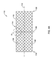
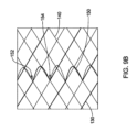
図1Aおよび図1Bは、先行技術のステント10の概略図である。先行技術のステント10は、第1の端部18と第2の端部20との間に延びる中心長手軸12によって画定されてよく、および/またはそれを有してよい。先行技術のステント10は、概して円筒状の外面14を画定する本体16を含んでよい。本体16は、第1の端部18から第2の端部20まで延びてよい。フレア端部分(図示せず)を有する先行技術のステント10では、本体16は、先行技術のステント10のフレア端部分の間に延びてよい。先行技術のステント10および/または本体16は、第1の方向に中心長手軸12の周りを延びる複数の第1のフィラメント30と、第2の方向に中心長手軸12の周りを延びる複数の第2のフィラメント40とを含んでよい。
1A and 1B are schematic diagrams of a prior art stent 10. The prior art stent 10 may be defined by and/or may have a central
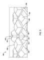
図2は、先行技術のステント10を形成するために使用される例示的な先行技術のマンドレル80の一部分を示す。先行技術のマンドレル80は、複数の第1のチャネル86および複数の第2のチャネル88を画定するように、マンドレル本体から径方向外方に延びる突起82を含んでよい。マンドレル本体の外面は、チャネル86/88の基部を画定し得る。複数の第1のフィラメント30および複数の第2のフィラメント40は、先行技術のステント10が実質的に均一な直径および/または外面を有するように、チャネル86/88内で突起82の間に配置されて先行技術のステント10を形成してよい。図3は、先行技術のステント10の一部分を示す詳細図であり、複数の第1のフィラメント30と複数の第2のフィラメント40とが編組管状部材を形成するように織り合わされている。織り合わされた第1のフィラメント30と第2のフィラメント40は、先行技術のステント10の外面を画定し得る。
2 shows a portion of an exemplary prior art mandrel 80 used to form a prior art stent 10. The prior art mandrel 80 may include projections 82 extending radially outward from the mandrel body to define a plurality of first channels 86 and a plurality of second channels 88. The outer surface of the mandrel body may define the base of the channels 86/88. The plurality of first filaments 30 and the plurality of
図4Aおよび図4Bは、本開示による医療用ステント110の態様を概略的に示す。医療用ステント110は、第1の端部118と、第2の端部120と、第1の端部118から第2の端部120まで延びる中心長手軸112とを有してよい。医療用ステント110は、管状本体116を含んでよく、管状本体116は、その中を通って第1の端部118から第2の端部120まで延びる管腔を画定している。管状本体116は、ステント110の外面114を画定し得る。いくつかの実施形態では、本体116は、第1の端部118から第2の端部120まで延びてよい。いくつかの実施形態では、医療用ステント110は、フレア状の第1の端部(図示せず)および/またはフレア状の第2の端部(図示せず)を含んでよい。それらの実施形態では、医療用ステント110の本体116は、第1の端部118からフレア状の第2の端部まで、フレア状の第1の端部から第2の端部120まで、またはフレア状の第1の端部からフレア状の第2の端部まで延びてよい。他の配列も考えられる。
4A and 4B show schematic views of a
以下の説明では、本体116が医療用ステント110の第1の端部118から医療用ステント110の第2の端部120まで延びると想定する。他の構成では、第1の端部118および第2の端部120はそれぞれ、本体116の第1の端部および本体116の第2の端部を指すとみなされてよい。医療用ステント110の本体116は、概して一定および/または均一の外径および/または外面114を有してよいが、上述されたように、場合によっては、本体116は1つまたは複数のフレア端を含んでよい。
In the following description, it is assumed that the
管状本体116は、編組管状フレームワークを形成するために、管状本体の長さに沿って互いに上下に交差しながら、らせん方向に延びる複数の編組フィラメントのような、複数の織り合わされたフィラメントから形成されてよい。例えば、医療用ステント110は、複数の第1のフィラメント130を含んでよく、それぞれの第1のフィラメントが、第1の端部118から第2の端部120に向かうおよび/または第2の端部120までの第1の方向(すなわち、第1のらせん方向)に中心長手軸112の周りを第1のらせん状経路で延びる。いくつかの実施形態では、第1の方向は時計回りであってよい。医療用ステント110は、複数の第2のフィラメント140を含んでよく、それぞれの第2のフィラメントが、第1の端部118から第2の端部120に向かうおよび/または第2の端部120までの第2の方向(すなわち、第2のらせん方向)に中心長手軸112の周りを第2のらせん状経路で延びる。いくつかの実施形態では、第2の方向は第1の方向と反対であってよい。いくつかの実施形態では、第2の方向は反時計回りであってよい。
The
いくつかの実施形態では、複数の第1のフィラメント130のうちの少なくとも1つの第1のらせん状経路は、第1の端部118と第2の端部120との間で本体116に沿って配置された周方向オフセットを含んでよい。例えば、複数の第1のフィラメント130の少なくとも1つは、第1のらせん状に延びる部分、第1のらせん状に延びる部分から周方向にオフセットされ第1のらせん状に延びる部分に実質的に平行である第2のらせん状に延びる部分、ならびに第1のらせん状に延びる部分と第2のらせん状に延びる部分との間に配置された周方向に延びる部分を含んでよい。
In some embodiments, the first helical path of at least one of the plurality of
いくつかの実施形態では、複数の第1のフィラメント130のうちの複数個の第1のフィラメントの第1のらせん状経路のそれぞれが、第1の端部118と第2の端部120との間で本体116に沿った周方向オフセットを含んでよい。いくつかの実施形態では、複数の第1のフィラメント130のそれぞれおよび/またはすべての第1のらせん状経路が、第1の端部118と第2の端部120との間で本体116に沿って配置された周方向オフセットを含んでよい。例えば、複数の第1のフィラメント130のそれぞれおよび/またはすべては、第1のらせん状に延びる部分、第1のらせん状に延びる部分から周方向にオフセットされ第1のらせん状に延びる部分に実質的に平行である第2のらせん状に延びる部分、ならびに第1のらせん状に延びる部分と第2のらせん状に延びる部分との間に配置された周方向に延びる部分を含んでよい。したがって、周方向オフセットは、管状本体のフィラメントの円弧状セグメントのような一体のセグメントとして形成されてよく、周方向オフセットを形成するフィラメントの円弧状セグメントは、管状本体の他のフィラメントと織り合わされた管状本体の周りにらせん状に延びるフィラメントの第1のらせん状に延びる部分および第2のらせん状に延びる部分の間に位置付けられる。周方向オフセットは、フィラメントが管状本体の周囲から外方へ曲がり、周方向オフセットの径方向外方突出部分(例えば、円弧状部分)が間に延びる、第1の基部および第2の基部を有してよい。周方向オフセットは、周方向オフセットの基部が、管状本体に沿って共通の長手方向位置および円周方向に離間された場所において長手方向に整合されるように、拡張可能なフレームワークの長手軸に対して垂直に配向されてよい。
In some embodiments, each of the first helical paths of the plurality of first filaments of the plurality of
加えてまたは代わりに、いくつかの実施形態では、複数の第2のフィラメント140のうちの少なくとも1つの第2のらせん状経路は、第1の端部118と第2の端部120との間で本体116に沿って配置された周方向オフセットを含んでよい。例えば、複数の第2のフィラメント140のうちの少なくとも1つは、第1のらせん状に延びる部分、第1のらせん状に延びる部分から周方向にオフセットされ第1のらせん状に延びる部分に実質的に平行である第2のらせん状に延びる部分、ならびに第1のらせん状に延びる部分と第2のらせん状に延びる部分との間に配置された周方向に延びる部分を含んでよい。いくつかの実施形態では、複数の第2のフィラメント140のうちの複数個の第2のフィラメントの第2のらせん状経路のそれぞれが、第1の端部118と第2の端部120との間で本体116に沿った周方向オフセットを含んでよい。いくつかの実施形態では、複数の第2のフィラメント140のそれぞれおよび/またはすべての第2のらせん状経路が、第1の端部118と第2の端部120との間で本体116に沿って配置された周方向オフセットを含んでよい。例えば、複数の第2のフィラメント140のそれぞれおよび/またはすべては、第1のらせん状に延びる部分、第1のらせん状に延びる部分から周方向にオフセットされ第1のらせん状に延びる部分に実質的に平行である第2のらせん状に延びる部分、ならびに第1のらせん状に延びる部分と第2のらせん状に延びる部分との間に配置された周方向に延びる部分を含んでよい。したがって、周方向オフセットは、管状本体のフィラメントの円弧状セグメントのような一体のセグメントとして形成されてよく、周方向オフセットを形成するフィラメントの円弧状セグメントは、管状本体の他のフィラメントと織り合わされた拡張可能なフレームワークの周りにらせん状に延びるフィラメントの第1のらせん状に延びる部分と第2のらせん状に延びる部分の間に位置付けられる。周方向オフセットは、フィラメントが管状本体の周囲から外方へ曲がり、周方向オフセットの径方向外方突出部分(例えば、円弧状部分)が間に延びる、第1の基部および第2の基部を有してよい。周方向オフセットは、周方向オフセットの基部が、管状本体に沿って共通の長手方向位置および円周方向に離間された場所において長手方向に整合されるように、管状本体の長手軸に対して垂直に配向されてよい。
Additionally or alternatively, in some embodiments, the second helical path of at least one of the plurality of
いくつかの実施形態では、複数の第1のフィラメント130のうちの少なくとも1つ(および/またはそのように構成される場合、複数の第2のフィラメント140のうちの少なくとも1つ)は、周方向オフセットで医療用ステント110の本体116の外面114から径方向外方に突出する移動防止ループ150を含んでよい。いくつかの実施形態では、周方向オフセットは、移動防止ループ150の少なくとも一部分を形成する。いくつかの実施形態では、周方向オフセットは、移動防止ループ150を形成する。いくつかの実施形態では、複数の第1のフィラメント130(および/または複数の第2のフィラメント140)のそれぞれが、周方向オフセットおよび/または移動防止ループ150を含んでよい。移動防止ループ150は、図4Aおよび図4Bでは、医療用ステント110の本体116の中央に配置されるように示されているが、移動防止ループ150は、医療用ステント110の本体116の長さに沿って任意の場所に配置されてよい。
In some embodiments, at least one of the first filaments 130 (and/or at least one of the
いくつかの実施形態では、医療用ステント110の本体116の外面114から径方向外方に突出する複数の移動防止ループ150が、医療用ステント110の本体116の周りに延びる移動防止ループ150の周方向列を形成してよい。いくつかの実施形態では、移動防止ループ150の周方向列内の複数の移動防止ループ150は、医療用ステント110の中心長手軸112に沿って共通の軸方向位置で軸方向および/または周方向に整合されてよい。
In some embodiments, a plurality of
いくつかの実施形態では、移動防止ループ150の少なくとも一部分が、医療用ステント110の中心長手軸112に対して実質的に垂直に配向されてよい。中心長手軸112に対して垂直に配向された移動防止ループ150は、中心長手軸112に対して斜角で配向された移動防止ループよりも、医療用ステント110がその場で軸移動に対して高い耐性があるようにし得る。
In some embodiments, at least a portion of the
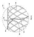
図5は、医療用ステント110を形成するためのマンドレル180の態様を示す。マンドレル180は、実質的に円筒体と、この円筒体から径方向外方に延びる複数の突出部182とを含んでよい。いくつかの実施形態では、複数の突出部182は、円筒体と一体であってよく、および/または一体的に形成されてよい。例えば、円筒体および複数の突出部182は、切断、機械加工、エッチング、研削、鋳造、射出成形などによって、単一片の材料から形成されてよい。
5 illustrates an embodiment of a
いくつかの実施形態では、複数の突出部182は、概してダイヤモンド形および/またはピラミッド形であってよい。例えば、複数の突出部182は、円筒体におけるより広い基部から、マンドレル180および/または円筒体の中心長手軸から最も外方の径方向端部におけるより狭い頂部に向かって先細になり得る。いくつかの実施形態では、複数の突出部182の1つもしくは複数またはそれぞれが、その最も外方の径方向端部において「点」を欠くことにより、突出部のいくぶん平坦な「頂部」を画定してよい。いくつかの実施形態では、突出部の「頂部」は、突出部の「頂部」において、マンドレル180および/または円筒体の中心長手軸からのマンドレル180の半径に関連付けされおよび/またはそれにより画定された、湾曲面または弧状面を有してよい。いくつかの実施形態では、複数の突出部182は、実質的に均一な高さを有してよく、ならびに/または、マンドレル180および/もしくは円筒体の中心長手軸に対して実質的に共通の径方向範囲まで延びてよい。他の構成も企図される。
In some embodiments, the plurality of
複数の突出部182は、マンドレル180の第1の端部からマンドレル180の第2の反対側端部に向かって第1の方向に円筒体の周りをらせん状に延びる複数の第1のチャネル186を画定してよい。いくつかの実施形態では、第1の方向は時計回りであってよい。複数の突出部182はまた、マンドレル180の第1の端部からマンドレル180の第2の反対側端部に向かって第1の方向と反対の第2の方向に円筒体の周りをらせん状に延びる複数の第2のチャネル188を画定してよい。いくつかの実施形態では、第2の方向は反時計回りであってよい。
The plurality of
少なくともいくつかの実施形態では、円筒体は、複数の第1のチャネル186および/または複数の第2のチャネル188の基部または底部を形成および/または画定してよい。例えば、円筒体は、マンドレル180および/または円筒体の中心長手軸に対して複数の第1のチャネル186および/または複数の第2のチャネル188の径方向に最も内方の範囲を形成してよい。いくつかの実施形態では、複数の突出部182は、複数の第1のチャネル186および/または複数の第2のチャネル188の両側面を画定してよい。いくつかの実施形態では、複数の第1のチャネル186および/または複数の第2のチャネル188は、円筒体から径方向外方へ、ならびに/またはマンドレル180および/もしくは円筒体の中心長手軸に対して開いてよい。いくつかの実施形態では、複数の第1のチャネル186および/または複数の第2のチャネル188は、複数の第1のチャネル186および/または複数の第2のチャネル188の基部または底部におけるよりも、複数の第1のチャネル186および/または複数の第2のチャネル188の径方向外方の範囲において、より広くなり得る。
In at least some embodiments, the cylinder may form and/or define the base or bottom of the
いくつかの実施形態では、複数の突出部182のうちの少なくともいくつかが、円筒体の周りを周方向に延びる、突出部に形成された(例えば、突出部の「頂部」に形成された)溝190を含む。溝190は、突出部から、円筒体から、ならびに/またはマンドレル180および/もしくは円筒体の中心長手軸に対して、径方向外方に開いてよい。いくつかの実施形態では、溝190は、マンドレル180および/または円筒体の中心長手軸に対して実質的に垂直に配向されてよい。例えば、溝190の中心線は、マンドレル180および/または円筒体の中心長手軸に対して垂直に配向された平面内に配置されてよい。いくつかの実施形態では、溝190は、複数の第1のチャネル186のうちの隣接する第1のチャネルを接続してよい。いくつかの実施形態では、溝190は、複数の第2のチャネル188のうちの隣接する第2のチャネルを接続してよい。いくつかの実施形態では、複数の突出部182のうちの形成された溝190を含む少なくともいくつかが、円筒体の周りに延びる突出部の周方向列を形成してよい。いくつかの実施形態では、溝190が形成された突出部の周方向列の各突出部の溝190は、マンドレル180および/または円筒体の中心長手軸に沿って共通の軸方向位置で軸方向および/または周方向に整合されてよい。
In some embodiments, at least some of the plurality of
いくつかの実施形態では、複数の突出部182のうちの形成された溝190を含む少なくともいくつかは、例えば、図5に示されるように、複数の突出部182のうちの残りの突出部よりも、円筒体から、ならびに/またはマンドレル180および/もしくは円筒体の中心長手軸に対して、径方向外方にさらに延びる隆起した突出部184であってよい。図5では、溝190を有する隆起した突出部184を示し、それにより、円筒体の周りに延びる突出部の周方向列も形成されているが、隆起した突出部184は、すべての実施形態で明白に必要なわけではなく、隆起した突出部184なしに、代わりに本明細書で説明されるような複数の突出部182のみを使用して、マンドレル180が作製されてもよく、その場合、複数の突出部182のうちの少なくともいくつかが溝190を含む。
In some embodiments, at least some of the plurality of
いくつかの実施形態では、複数の突出部182のうちの形成された溝190を含む少なくともいくつかが、円筒体の周りに延びる突出部の複数の周方向列を形成してよい。いくつかの実施形態では、溝190が形成された突出部の1つの周方向列内の各突出部の溝190は、マンドレル180および/または円筒体の中心長手軸に沿って共通の軸方向位置で軸方向および/または周方向に整合されてよい。突出部の複数の周方向列は、マンドレル180および/または円筒体に沿って互いに長手方向に離間されてよい。
In some embodiments, at least some of the plurality of
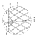
図6は、本明細書に説明されるような医療用ステント110の一部分を示す詳細図である。特定の特徴の間の関係を示すために、図6はまっすぐに側面から見たものとして示されていないことを、当業者は認識されよう。代わりに、特徴をより容易に見て理解できるようにするために、わずかな角度が図に導入されている。さらに、複数の第1のフィラメント130のうちの1つのフィラメントが、見る人に対してフィラメントおよび第1のらせん状経路を目立たせるために網掛けで示されており、断面を示すことは意図されていない。
Figure 6 is a detailed view of a portion of a
本明細書に論じられているように、医療用ステント110は、複数の第1のフィラメント130および複数の第2のフィラメント140を含んでよい。複数の第1のフィラメント130のうちの少なくとも1つは、第1のらせん状に延びる部分と第2のらせん状に延びる部分との間に配置された周方向オフセットを含んでよい。周方向オフセットは、移動防止ループ150を形成してよい。少なくともいくつかの実施形態では、複数の第1のフィラメント130は、例えば編組を形成するときなどに、複数の第2のフィラメント140と織り合わされてよい。図6は、織り合わされたフィラメントの上-下-上パターンを示す。他の構成および/またはパターンも企図される。
As discussed herein, the
いくつかの実施形態では、複数の第1のフィラメント130と複数の第2のフィラメント140とを織り合わせることが、第1のフィラメントと第2のフィラメントが互いに対して上および/または下に交差する複数の交点を画定する。複数の第1のフィラメント130のうちの少なくとも1つの第1のらせん状経路は、周方向オフセットおよび/または移動防止ループ150の第1の端部152において複数の第2のフィラメント140のうちの第1の1つの下を通過してよく、周方向オフセットおよび/または移動防止ループ150の第2の端部154において複数の第2のフィラメント140のうちの第2の1つの下を通過してよい。少なくともいくつかの実施形態では、複数の第2のフィラメント140のうちの第2の1つは、複数の第2のフィラメント140のうちの第1の1つに隣接してよい。この配列では、複数の第1のフィラメント130のうちの少なくとも1つ(例えば、図6における網掛けされたフィラメント)が、複数の第2のフィラメント140のうちの2つの隣接するフィラメントの下を通過してよい。これは、周方向オフセット、および移動防止ループ150の形成によって可能にされ、移動防止ループ150は、複数の第1のフィラメント130と複数の第2のフィラメント140との2つの隣接する交点の間で医療用ステント110の本体116の外面114から径方向外方に延びる。
In some embodiments, the interweaving of the plurality of
いくつかの実施形態では、医療用ステント110はカバード・ステントであってよい。したがって、医療用ステント110は、複数の第1のフィラメント130および複数の第2のフィラメント140に配置および/または付着された被覆160を含んでよい。被覆160は、複数の第1のフィラメント130および複数の第2のフィラメント140の隣接するフィラメントの間の隙間にまたがってよい。少なくともいくつかの実施形態では、被覆160は、流体、デブリ、および/または組織内殖に対して不浸透性であり得る。いくつかの実施形態では、被覆160は、医療用ステント110の本体に沿って第1の端部から第2の端部まで延びてよい。いくつかの実施形態では、被覆160は、医療用ステント110の全長に沿って延びてよい。いくつかの実施形態では、被覆160は本体の内面、本体の外面、もしくは本体の内面と外面の両方に配置されてよく、または移動防止ループ150が被覆160から径方向外方に突出する状態で本体が被覆160内に埋め込まれてもよい。他の構成も企図される。
In some embodiments, the
上記に論じられ、また図6に示されるように、移動防止ループ150の少なくとも一部分は、医療用ステント110の中心長手軸に対して実質的に垂直に配向されてよい。代替構成では、図7に見られるように、移動防止ループ150の一部分が第2の端部120に向かって角度を付けられてよい。いくつかの実施形態では、移動防止ループ150の径方向外側部分(径方向で外側の半分または径方向で外側の半分未満)のみが第2の端部120に向かって角度を付けられてよく、移動防止ループ150の径方向内側部分(径方向で内側の半分または残部)は、医療用ステント110の中心長手軸に対して実質的に垂直に配向され得る。別の代替構成では、図8に見られるように、移動防止ループ150の一部分が第1の端部118に向かって角度を付けられてよい。いくつかの実施形態では、移動防止ループ150の径方向外側部分(径方向で外側の半分または径方向で外側の半分未満)のみが第1の端部118に向かって角度を付けられてよく、移動防止ループ150の径方向内側部分(径方向で内側の半分または残部)は、医療用ステント110の中心長手軸に対して実質的に垂直に配向され得る。他の構成も企図される。
As discussed above and shown in FIG. 6, at least a portion of the
図9Aおよび図9Bは、医療用ステント110を形成するのに使用される第1のらせん状経路および第2のらせん状経路の態様を概略的に示す。経路および/または様々な要素をより明瞭にし、理解しやすくするために、いくつかの特徴が、隣接する特徴から見分けられるように太字またはより太い線で示されている。特徴の物理的な厚さ(または他の特性)の違いは、この表現から意図または示唆されない。
9A and 9B show schematic views of first and second helical pathways used to form a
上記に論じられたように、複数の第1のフィラメント130のうちの少なくとも1つの第1のらせん状経路は、第1の端部118と第2の端部120との間で本体116に沿って配置された周方向オフセットを含んでよい。周方向オフセットは、移動防止ループ150を形成してよい。複数の第1のフィラメント130のうちの少なくとも1つの第1のらせん状経路は、周方向オフセットおよび/または移動防止ループ150の第1の端部152において複数の第2のフィラメント140のうちの第1の1つの下を通過してよく、周方向オフセットおよび/または移動防止ループ150の第2の端部154において複数の第2のフィラメント140のうちの第2の1つの下を通過してよい。図9A~図9Bに見られ得るように、複数の第1のフィラメント130のうちの少なくとも1つは、第1のらせん状に延びる部分(移動防止ループ150に向かって右下方に角度を付けて示される)、第1のらせん状に延びる部分から周方向にオフセットされ第1のらせん状に延びる部分に実質的に平行である第2のらせん状に延びる部分(移動防止ループ150から離れるように右下方に角度を付けて示される)、ならびに第1のらせん状に延びる部分と第2のらせん状に延びる部分との間に配置された周方向に延びる部分を含んでよい。
As discussed above, the first helical path of at least one of the plurality of
図10は、マンドレル180を使用して医療用ステント110を形成する方法の態様を示す。この方法は、マンドレル180を使用する工程を含んでよく、マンドレル180は、円筒体と、円筒体から径方向外方に延びる複数の突出部182とを備えてよい。複数の突出部182は、第1の方向に円筒体の周りをらせん状に延びる複数の第1のチャネル186と、第1の方向と反対の第2の方向に円筒体の周りをらせん状に延びる複数の第2のチャネル188とを画定してよい。複数の突出部182のうちの少なくともいくつかには、円筒体の周りを周方向に延びる溝190が形成されている。
10 illustrates an embodiment of a method for forming a
この方法は、第1の方向に複数の第1のチャネル186内でマンドレル180および/または円筒体の周りに複数の第1のフィラメント130を巻き付け、第2の方向に複数の第2のチャネル188内でマンドレル180および/または円筒体の周りに複数の第2のフィラメント140を巻き付けて、複数の第1のフィラメント130と複数の第2のフィラメント140とが織り合わされて医療用ステント110の本体を画定するようにする工程を含んでよい。
The method may include winding a plurality of
この方法は、複数の第1のフィラメント130のうちの少なくともいくつかが、複数の突出部182のうちの形成された溝190を含む少なくともいくつかの上に巻き付けられることを含んでよい。複数の第1のフィラメント130のうちの少なくともいくつかを、複数の突出部182のうちの形成された溝190を含む少なくともいくつかの上に巻き付けることは、図10に見られるように、医療用ステント110の本体から径方向外方に延びる複数の移動防止ループ150を形成し得る。複数の突出部182のうちの少なくともいくつかに形成された溝190は、マンドレル180および/または円筒体および/またはその中心長手軸の周りを周方向に延びてよい。
The method may include winding at least some of the
溝190が形成された複数の突出部182の上に複数の第1のフィラメント130のうちの少なくともいくつかを巻き付けることにより、複数の第1のフィラメント130のうちの少なくともいくつかの第1のらせん状経路が周方向オフセットを有することになる。複数の第1のフィラメント130のうちの少なくともいくつかを、複数の突出部182のうちの溝190が形成された少なくともいくつかの上に溝190内で巻き付けることは、これらの第1のフィラメントを、1つの第1のチャネルから隣接する第1のチャネルへ移し得る。溝190が形成された複数の突出部182の上に複数の第1のフィラメント130のうちの少なくともいくつかを巻き付けることにより、複数の第1のフィラメント130のうちの少なくともいくつかの周方向に延びる部分および/または移動防止ループ150が、複数の第1のチャネル186および複数の第2のチャネル188によって形成および/または画定される医療用ステント110の本体から径方向外方に延びることにもなる。各移動防止ループ150は、複数の第2のフィラメント140のうちの2つの隣接する第2のフィラメントの間で医療用ステント110の本体から径方向外方に延びてよい。
By winding at least some of the
本明細書に論じられたように、いくつかの実施形態では、複数の突出部182のうちの形成された溝190を含む少なくともいくつかは、複数の突出部182のうちの残りの突出部よりも、円筒体から、ならびに/またはマンドレル180および/もしくは円筒体の中心長手軸に対して、径方向外方にさらに延びる隆起した突出部184であってよい。隆起した突出部184の上に複数の第1のフィラメント130のうちの少なくともいくつかを巻き付けることにより、複数の第1のフィラメント130のうちの少なくともいくつかの周方向に延びる部分および/または移動防止ループ150が、溝190が形成された複数の突出部182の上に複数の第1のフィラメント130のうちの少なくともいくつかを巻き付けるよりも、医療用ステント110の本体から径方向外方にさらに延びることになる。
As discussed herein, in some embodiments, at least some of the plurality of
図10に見られるように、複数の突出部182のうちの形成された溝190を含む少なくともいくつかの上に巻き付けられた複数の第1のフィラメント130のうちの少なくともいくつかの各第1のフィラメントが、溝190の第1の端部におけるおよび/またはそれに隣接する複数の第2のフィラメント140のうちの第1の1つの下に、ならびに溝190の第2の端部におけるおよび/またはそれに隣接する複数の第2のフィラメント140のうちの第2の1つの下に延びる。複数の第2のフィラメント140のうちの第2の1つは、複数の第2のフィラメント140のうちの第1の1つに隣接してよい。複数の突出部182のうちの形成された溝190を含む少なくともいくつかの上に巻き付けられた複数の第1のフィラメント130のうちの少なくともいくつかの各第1のフィラメントが、周方向オフセットおよび/または移動防止ループ150の第1の端部152におけるおよび/またはそれに隣接する複数の第2のフィラメント140のうちの第1の1つの下に、ならびに周方向オフセットおよび/または移動防止ループ150の第2の端部154におけるおよび/またはそれに隣接する複数の第2のフィラメント140のうちの第2の1つの下に延びる。少なくともいくつかの実施形態では、周方向オフセットおよび/または移動防止ループ150の第1の端部152は、溝190の第1の端部内に配置されてよく、周方向オフセットおよび/または移動防止ループ150の第2の端部154は、溝190の第2の端部内に配置されてよい。
10, each first filament of at least some of the plurality of
図11は、本開示による代替的な医療用ステント210の態様を概略的に示す。医療用ステント210は、医療用ステント110と同じ方法で形成されてよく、および/または同じもしくは同様の特徴を含んでよい。同様の特徴は同様の参照番号を使用して識別され得る。医療用ステント210は、第1の端部と、第2の端部と、第1の端部から第2の端部まで延びる中心長手軸212とを有してよい。医療用ステント210は、外面214を画定する本体216を含んでよい。いくつかの実施形態では、本体216は、第1の端部から第2の端部まで延びてよい。医療用ステント110に関して本明細書に説明される他の構成も企図される。
11 illustrates a schematic view of an alternative
医療用ステント210は、複数の第1のフィラメント230を含んでよく、それぞれの第1のフィラメントが、第1の端部から第2の端部に向かうおよび/または第2の端部までの第1の方向に中心長手軸212の周りを第1のらせん状経路で延びる。いくつかの実施形態では、第1の方向は時計回りであってよい。医療用ステント210は、複数の第2のフィラメント240を含んでよく、それぞれの第2のフィラメントが、第1の端部から第2の端部に向かうおよび/または第2の端部までの第2の方向に中心長手軸212の周りを第2のらせん状経路で延びる。いくつかの実施形態では、第2の方向は第1の方向と反対であってよい。いくつかの実施形態では、第2の方向は反時計回りであってよい。
The
いくつかの実施形態では、複数の第1のフィラメント230のうちの少なくとも1つの第1のらせん状経路は、第1の端部と第2の端部との間で本体216に沿って配置された周方向オフセットを含んでよい。例えば、複数の第1のフィラメント230の少なくとも1つは、第1のらせん状に延びる部分、第1のらせん状に延びる部分から周方向にオフセットされ第1のらせん状に延びる部分に実質的に平行である第2のらせん状に延びる部分、ならびに第1のらせん状に延びる部分と第2のらせん状に延びる部分との間に配置された周方向に延びる部分を含んでよい。
In some embodiments, the first helical path of at least one of the plurality of
いくつかの実施形態では、複数の第1のフィラメント230のうちの複数個の第1のフィラメントの第1のらせん状経路のそれぞれが、第1の端部と第2の端部との間で本体216に沿った周方向オフセットを含んでよい。いくつかの実施形態では、複数の第1のフィラメント230のそれぞれおよび/またはすべての第1のらせん状経路が、第1の端部と第2の端部との間で本体216に沿って配置された周方向オフセットを含んでよい。例えば、複数の第1のフィラメント230のそれぞれおよび/またはすべては、第1のらせん状に延びる部分、第1のらせん状に延びる部分から周方向にオフセットされ第1のらせん状に延びる部分に実質的に平行である第2のらせん状に延びる部分、ならびに第1のらせん状に延びる部分と第2のらせん状に延びる部分との間に配置された周方向に延びる部分を含んでよい。いくつかの実施形態では、複数の第1のフィラメント230のうちの少なくとも1つの第1のらせん状経路は、第1の端部と第2の端部との間で互いに長手方向に離間された複数の周方向オフセットを含む。
In some embodiments, each of the first helical paths of the plurality of first filaments of the plurality of
加えてまたは代わりに、いくつかの実施形態では、複数の第2のフィラメント240のうちの少なくとも1つの第2のらせん状経路は、第1の端部と第2の端部との間で本体216に沿って配置された周方向オフセットを含んでよい。例えば、複数の第2のフィラメント240のうちの少なくとも1つは、第1のらせん状に延びる部分、第1のらせん状に延びる部分から周方向にオフセットされ第1のらせん状に延びる部分に実質的に平行である第2のらせん状に延びる部分、ならびに第1のらせん状に延びる部分と第2のらせん状に延びる部分との間に配置された周方向に延びる部分を含んでよい。いくつかの実施形態では、複数の第2のフィラメント240のうちの複数個の第2のフィラメントの第2のらせん状経路のそれぞれが、第1の端部と第2の端部との間で本体216に沿った周方向オフセットを含んでよい。いくつかの実施形態では、複数の第2のフィラメント240のそれぞれおよび/またはすべての第2のらせん状経路が、第1の端部と第2の端部との間で本体216に沿って配置された周方向オフセットを含んでよい。例えば、複数の第2のフィラメント240のそれぞれおよび/またはすべては、第1のらせん状に延びる部分、第1のらせん状に延びる部分から周方向にオフセットされ第1のらせん状に延びる部分に実質的に平行である第2のらせん状に延びる部分、ならびに第1のらせん状に延びる部分と第2のらせん状に延びる部分との間に配置された周方向に延びる部分を含んでよい。いくつかの実施形態では、複数の第2のフィラメント240のうちの少なくとも1つの第2のらせん状経路は、第1の端部と第2の端部との間で互いに長手方向に離間された複数の周方向オフセットを含む。
Additionally or alternatively, in some embodiments, the second helical path of at least one of the plurality of
いくつかの実施形態では、複数の第1のフィラメント230のうちの少なくとも1つ(および/またはそのように構成される場合、複数の第2のフィラメント240のうちの少なくとも1つ)は、周方向オフセットで医療用ステント210の本体216の外面214から径方向外方に突出する移動防止ループ250を含んでよい。いくつかの実施形態では、周方向オフセットは、移動防止ループ250の少なくとも一部分を形成する。いくつかの実施形態では、周方向オフセットは、移動防止ループ250を形成する。いくつかの実施形態では、複数の第1のフィラメント230(および/または複数の第2のフィラメント240)のそれぞれが、周方向オフセットおよび/または移動防止ループ250を含んでよい。いくつかの実施形態では、複数の第1のフィラメント230のうちの少なくとも1つ(および/またはそのように構成される場合、複数の第2のフィラメント240のうちの少なくとも1つ)は、複数の周方向オフセットで医療用ステント210の本体216の外面214から径方向外方に突出する複数の移動防止ループ250を含んでよい。
In some embodiments, at least one of the first filaments 230 (and/or at least one of the
いくつかの実施形態では、医療用ステント210の本体216の外面214から径方向外方に突出する複数の移動防止ループ250は、医療用ステント210の本体216の周りに延びる移動防止ループ250の複数の周方向列を形成してよい。いくつかの実施形態では、移動防止ループ250の1つの周方向列内の移動防止ループ250が、医療用ステント210の中心長手軸212に沿って共通の軸方向位置で軸方向および/または周方向に整合されてよい。移動防止ループ250の複数の周方向列が、医療用ステント210の本体216に沿って互いに長手方向に離間されてよい。
In some embodiments, the multiple
いくつかの実施形態では、移動防止ループ250の少なくとも一部分は、医療用ステント210の中心長手軸212に対して実質的に垂直に配向されてよい。中心長手軸212に対して垂直に配向された移動防止ループ250は、中心長手軸212に対して斜角で配向された移動防止ループよりも、医療用ステント210がその場で軸移動に対して高い耐性があるようにし得る。
In some embodiments, at least a portion of the
図12は、本明細書に説明されるような医療用ステント210の一部分を示す詳細図である。特定の特徴の間の関係を示すために、図12はまっすぐに側面から見たものとして示されていないことを、当業者は認識されよう。代わりに、特徴をより容易に見て理解できるようにするために、わずかな角度が図に導入されている。さらに、複数の第1のフィラメント230のうちの1つのフィラメントが、見る人に対してフィラメントおよび第1のらせん状経路を目立たせるために網掛けで示されており、断面を示すことは意図されていない。
12 is a detailed view of a portion of a
本明細書に論じられているように、医療用ステント210は、複数の第1のフィラメント230および複数の第2のフィラメント240を含んでよい。複数の第1のフィラメント230のうちの少なくとも1つは、第1のらせん状に延びる部分と第2のらせん状に延びる部分との間に配置された周方向オフセットを含んでよい。周方向オフセットは、移動防止ループ250を形成してよい。少なくともいくつかの実施形態では、複数の第1のフィラメント230は、例えば編組を形成するときなどに、複数の第2のフィラメント240と織り合わされてよい。図12は、織り合わされたフィラメントの上-下-上パターンを示す。他の構成および/またはパターンも企図される。
As discussed herein, the
いくつかの実施形態では、複数の第1のフィラメント230と複数の第2のフィラメント240とを織り合わせることが、第1のフィラメントと第2のフィラメントが互いに対して上および/または下に交差する複数の交点を画定する。複数の第1のフィラメント230のうちの少なくとも1つの第1のらせん状経路は、周方向オフセットおよび/または移動防止ループ250の第1の端部において複数の第2のフィラメント240のうちの第1の1つの下を通過してよく、周方向オフセットおよび/または移動防止ループ250の第2の端部において複数の第2のフィラメント240のうちの第2の1つの下を通過してよい。少なくともいくつかの実施形態では、複数の第2のフィラメント240のうちの第2の1つは、複数の第2のフィラメント240のうちの第1の1つに隣接してよい。この配列では、複数の第1のフィラメント230のうちの少なくとも1つ(例えば、図12における網掛けされたフィラメント)が、複数の第2のフィラメント240のうちの2つの隣接するフィラメントの下を通過してよい。これは、周方向オフセット、および移動防止ループ250の形成によって可能にされ、移動防止ループ250は、複数の第1のフィラメント230と複数の第2のフィラメント240との2つの隣接する交点の間で医療用ステント210の本体の外面から径方向外方に延びる。
In some embodiments, the interweaving of the plurality of
いくつかの実施形態では、複数の第1のフィラメント230のうちの少なくとも1つの第1のらせん状経路は、第1の端部と第2の端部との間で互いに長手方向に離間された複数の周方向オフセットを含む。いくつかの実施形態では、複数の第1のフィラメント230のうちの少なくとも1つは、複数の周方向オフセットで医療用ステント210の本体の外面から径方向外方に突出する複数の移動防止ループ250を含んでよい。例えば、各周方向オフセットが移動防止ループ250を形成してよく、図12に示されるように、複数の第1のフィラメント230の単一の第1のフィラメントから形成された、および/またはそのフィラメント内に形成された複数の移動防止ループ250が存在してよい。
In some embodiments, the first helical path of at least one of the plurality of
いくつかの実施形態では、医療用ステント210の本体の外面から径方向外方に突出する複数の移動防止ループ250は、医療用ステント210の本体の周りに延びる移動防止ループ250の複数の周方向列を形成してよい。いくつかの実施形態では、移動防止ループ250の1つの周方向列内の移動防止ループ250が、医療用ステント210の中心長手軸に沿って共通の軸方向位置で軸方向および/または周方向に整合されてよい。移動防止ループ250の複数の周方向列が、医療用ステント210の本体に沿って互いに長手方向に離間されてよい。
In some embodiments, the multiple
いくつかの実施形態では、医療用ステント210はカバード・ステントであってよい。したがって、医療用ステント210は、複数の第1のフィラメント230および複数の第2のフィラメント240に配置および/または付着された被覆260を含んでよい。被覆260は、複数の第1のフィラメント230および複数の第2のフィラメント240の隣接するフィラメントの間の隙間にまたがってよい。少なくともいくつかの実施形態では、被覆260は、流体、デブリ、および/または組織内殖に対して不浸透性であり得る。いくつかの実施形態では、被覆260は、医療用ステント210の本体に沿って第1の端部から第2の端部まで延びてよい。いくつかの実施形態では、被覆260は、医療用ステント210の全長に沿って延びてよい。いくつかの実施形態では、被覆260は本体の内面、本体の外面、もしくは本体の内面と外面の両方に配置されてよく、または移動防止ループ250が被覆260から径方向外方に突出する状態で本体が被覆260内に埋め込まれてもよい。他の構成も企図される。
In some embodiments, the
上記に論じられ、また図12に示されるように、移動防止ループ250の少なくとも一部分は、医療用ステント210の中心長手軸に対して実質的に垂直に配向されてよい。代替構成では、移動防止ループ250の一部分が第2の端部に向かって角度を付けられてよい。いくつかの実施形態では、移動防止ループ250の径方向外側部分(径方向で外側の半分または径方向で外側の半分未満)のみが第2の端部に向かって角度を付けられてよく、移動防止ループ250の径方向内側部分(径方向で内側の半分または残部)は、医療用ステント210の中心長手軸に対して実質的に垂直に配向され得る。別の代替構成では、移動防止ループ250の一部分が第1の端部に向かって角度を付けられてよい。いくつかの実施形態では、移動防止ループ250の径方向外側部分(径方向で外側の半分または径方向で外側の半分未満)のみが第1の端部に向かって角度を付けられてよく、移動防止ループ250の径方向内側部分(径方向で内側の半分または残部)は、医療用ステント210の中心長手軸に対して実質的に垂直に配向され得る。他の構成も企図される。
As discussed above and shown in FIG. 12, at least a portion of the
当業者は、本明細書で記載されまた企図される特定の実施形態以外の様々な形態で本発明が明示され得ることを認識するであろう。したがって、添付の特許請求の範囲に記載されるような本発明の範囲および趣旨から逸脱することなく、形態および詳細の変更が行われ得る。 Those skilled in the art will recognize that the present invention may be manifested in a variety of forms other than the specific embodiments described and contemplated herein. Accordingly, changes may be made in form and detail without departing from the scope and spirit of the present invention as set forth in the appended claims.
本明細書に開示されている医療用ステント、マンドレル、およびその様々な要素の様々な構成要素のために使用され得る材料は、医療デバイスおよびマンドレルに一般的に関連付けられるものを含み得る。簡単にするために、以下の説明では装置に言及する。しかしながら、これは、本明細書に記載のデバイスおよび方法を限定するようには意図されず、その説明は、本明細書に開示されている他の要素、部材、構成要素、またはデバイス、例えば、以下に限定されないが、医療用ステント、マンドレル、フィラメント、移動防止ループ、被覆、および/またはその要素もしくは構成要素などに適用され得る。 Materials that may be used for the various components of the medical stents, mandrels, and various elements thereof disclosed herein may include those commonly associated with medical devices and mandrels. For simplicity, the following description refers to apparatus. However, this is not intended to limit the devices and methods described herein, and the description may apply to other elements, members, components, or devices disclosed herein, such as, but not limited to, medical stents, mandrels, filaments, anti-migration loops, coatings, and/or elements or components thereof.
いくつかの実施形態では、装置および/またはその構成要素は、金属、金属合金、ポリマー(そのいくつかの例は後で開示される)、金属-ポリマー複合材、セラミック、それらの組み合わせなど、または他の適切な材料から作られてよい。 In some embodiments, the device and/or its components may be made from metals, metal alloys, polymers (some examples of which are disclosed below), metal-polymer composites, ceramics, combinations thereof, etc., or other suitable materials.
適切なポリマーのいくつかの例は、ポリテトラフルオロエチレン(PTFE)、エチレンテトラフルオロエチレン(ETFE)、フッ化エチレンプロピレン(FEP)、ポリオキシメチレン(POM、例えば、DuPontから入手可能なDELRIN(登録商標))、ポリエーテルブロックエステル、ポリウレタン(例えば、ポリウレタン85A)、ポリプロピレン(PP)、ポリ塩化ビニル(PVC)、ポリエーテルエステル(例えば、DSM Engineering Plasticsから入手可能なARNITEL(登録商標))、エーテルまたはエステル系コポリマー(例えば、ブチレン/ポリ(アルキレンエーテル)フタレート、および/またはDuPontから入手可能なHYTREL(登録商標)などの他のポリエステルエラストマー)、ポリアミド(例えば、Bayerから入手可能なDURETHAN(登録商標)またはElf Atochemから入手可能なCRISTAMID(商標))、エラストマーポリアミド、ブロックポリアミド/エーテル、ポリエーテルブロックアミド(PEBA、例えば、商標名PEBAX(登録商標)で入手可能)、エチレンビニルアセテートコポリマー(EVA)、シリコーン、ポリエチレン(PE)、MARLEX(登録商標)高密度ポリエチレン、MARLEX(登録商標)低密度ポリエチレン、直鎖状低密度ポリエチレン(例えば、REXELL(商標))、ポリエステル、ポリブチレンテレフタレート(PBT)、ポリエチレンテレフタレート(PET)、ポリトリメチレンテレフタレート、ポリエチレンナフタレート(PEN)、ポリエーテルエーテルケトン(PEEK)、ポリイミド(PI)、ポリエーテルイミド(PEI)、ポリフェニレンスルフィド(PPS)、ポリフェニレンオキシド(PPO)、ポリパラフェニレンテレフタルアミド(例えば、KEVLAR(登録商標))、ポリスルホン、ナイロン、ナイロン-12(例えば、EMS American Grilonから入手可能なGRILAMID(登録商標))、パーフルオロ(プロピルビニルエーテル)(PFA)、エチレンビニルアルコール、ポリオレフィン、ポリスチレン、エポキシ、ポリ塩化ビニリデン(PVdC)、ポリ(スチレン-b-イソブチレン-b-スチレン)(例えば、SIBSおよび/またはSIBS50A)、ポリカーボネート、ポリウレタンシリコーンコポリマー(例えば、Aortech BiomaterialsからのElastEon(商標)、またはAdvanSource BiomaterialsからのChronoSil(商標))、生体適合性ポリマー、他の適切な材料、または混合物、組み合わせ、これらのコポリマー、およびポリマー/金属複合材などを含み得る。いくつかの実施形態では、シースが液晶ポリマー(LCP)と混合され得る。例えば、混合物は最大約6パーセントのLCPを含有し得る。 Some examples of suitable polymers are polytetrafluoroethylene (PTFE), ethylene tetrafluoroethylene (ETFE), fluorinated ethylene propylene (FEP), polyoxymethylene (POM, e.g., DELRIN® available from DuPont), polyether block esters, polyurethanes (e.g., Polyurethane 85A), polypropylene (PP), polyvinyl chloride (PVC), polyetheresters (e.g., ARNITEL® available from DSM Engineering Plastics), ether or ester based copolymers (e.g., butylene/poly(alkylene ether) phthalates, and/or other polyester elastomers such as HYTREL® available from DuPont), polyamides (e.g., DURETHAN® or Elf® available from Bayer), and polyether esters (e.g., POLY(ETHYLENE ETHER) available from Bayer). Atochem (CRISTAMID™), elastomeric polyamides, block polyamide/ethers, polyether block amides (PEBA, available, for example, under the trade name PEBAX®), ethylene vinyl acetate copolymers (EVA), silicones, polyethylene (PE), MARLEX® high density polyethylene, MARLEX® low density polyethylene, linear low density polyethylene (for example, REXELL™), polyesters, polybutylene terephthalate (PBT), polyethylene terephthalate (PET), polytrimethylene terephthalate, polyethylene naphthalate (PEN), polyether ether ketone (PEEK), polyimides (PI), polyetherimide (PEI), polyphenylene sulfide (PPS), polyphenylene oxide (PPO), polyparaphenylene terephthalamide (for example, KEVLAR®), polysulfones, nylons, nylon-12 (for example, EMS American The sheath may include, for example, GRILAMID® available from Grilon, perfluoro(propyl vinyl ether) (PFA), ethylene vinyl alcohol, polyolefins, polystyrene, epoxies, polyvinylidene chloride (PVdC), poly(styrene-b-isobutylene-b-styrene) (e.g., SIBS and/or SIBS50A), polycarbonates, polyurethane silicone copolymers (e.g., ElastEon™ from Aortech Biomaterials, or ChronoSil™ from AdvanSource Biomaterials), biocompatible polymers, other suitable materials, or mixtures, combinations, copolymers thereof, and polymer/metal composites. In some embodiments, the sheath may be blended with a liquid crystal polymer (LCP). For example, the blend may contain up to about 6 percent LCP.
適切な金属および金属合金のいくつかの例は、304V、304L、および316LVステンレス鋼などのステンレス鋼;軟鋼;線形弾性および/もしくは超弾性ニチノールなどのニッケル-チタン合金;他のニッケル合金、例えば、ニッケル-クロム-モリブデン合金(例えば、INCONEL(登録商標)625などのUNS:N06625、HASTELLOY(登録商標)C-22(登録商標)などのUNS:N06022、HASTELLOY(登録商標)C276(商標)などのUNS:N10276、および他のHASTELLOY(登録商標)合金など)、ニッケル-銅合金(例えば、MONEL(登録商標)400、NICKELVAC(商標)400、NICORROS(登録商標)400などのUNS:N04400)、ニッケル-コバルト-クロム-モリブデン合金(例えば、MP35-N(商標)などのUNS:R30035)、ニッケル-モリブデン合金(例えば、HASTELLOY(登録商標)ALLOY B2(商標)などのUNS:N10665)、他のニッケル-クロム合金、他のニッケル-モリブデン合金、他のニッケル-コバルト合金、他のニッケル-鉄合金、他のニッケル-銅合金、他のニッケル-タングステンもしくはタングステン合金など;コバルト-クロム合金;コバルト-クロム-モリブデン合金(例えば、ELGILOY(登録商標)およびPHYNOX(登録商標)などのUNS:R30003);白金富化ステンレス鋼;チタン;白金;パラジウム;金;これらの組み合わせ;または他の任意の適切な材料を含む。 Some examples of suitable metals and metal alloys are stainless steels, such as 304V, 304L, and 316LV stainless steel; mild steel; nickel-titanium alloys, such as linear elastic and/or superelastic Nitinol; other nickel alloys, for example, nickel-chromium-molybdenum alloys (e.g., UNS: N06625, such as INCONEL® 625; UNS: N06022, such as HASTELLOY® C-22®; UNS: N06024, such as HASTELLOY® C-22®; 276™, and other HASTELLOY® alloys), nickel-copper alloys (e.g., UNS:N04400, such as MONEL® 400, NICKELVAC™ 400, NICORROS® 400), nickel-cobalt-chromium-molybdenum alloys (e.g., UNS:R30035, such as MP35-N™), nickel-molybdenum alloys (e.g., HASTELLOY® ALLOY™, B2™, UNS: N10665), other nickel-chromium alloys, other nickel-molybdenum alloys, other nickel-cobalt alloys, other nickel-iron alloys, other nickel-copper alloys, other nickel-tungsten or tungsten alloys, etc.; cobalt-chromium alloys; cobalt-chromium-molybdenum alloys (e.g., UNS: R30003, such as ELGILOY® and PHYNOX®); platinum-rich stainless steels; titanium; platinum; palladium; gold; combinations thereof; or any other suitable material.
少なくともいくつかの実施形態では、装置の部分もしくは全部および/またはその構成要素が、放射線不透過性材料でドープされ、または放射線不透過性材料で作られ、または別様に放射線不透過性材料を含んでもよい。放射線不透過性材料は、医療処置中に蛍光透視スクリーンまたは他の撮像技術において比較的明るい画像を生成できる材料であると理解される。この比較的明るい画像は、装置のユーザがその場所を決定するのを支援する。放射線不透過性材料のいくつかの例は、金、白金、パラジウム、タンタル、タングステン合金、放射線不透過性フィラーを加えたポリマー材料などを含み得るが、これらに限定されない。さらに、同じ結果を達成するために、他の放射線不透過性マーカバンドおよび/またはコイルが装置の設計に組み込まれてもよい。 In at least some embodiments, portions or all of the device and/or its components may be doped with, made of, or otherwise include radiopaque materials. A radiopaque material is understood to be a material capable of producing a relatively bright image on a fluoroscopy screen or other imaging technique during a medical procedure. This relatively bright image assists the user of the device in determining its location. Some examples of radiopaque materials may include, but are not limited to, gold, platinum, palladium, tantalum, tungsten alloys, polymeric materials with radiopaque fillers, and the like. Additionally, other radiopaque marker bands and/or coils may be incorporated into the design of the device to achieve the same results.
いくつかの実施形態では、ある程度の磁気共鳴画像法(MRI)適合性が、本明細書に開示された装置および/または他の要素に付与される。例えば、装置および/またはその構成要素もしくは部分は、実質的に画像を歪ませず、また実質的なアーチファクト(例えば、画像におけるギャップ)を生成しない材料で作られてよい。例えば、特定の強磁性材料は、MRI画像にアーチファクトを生成する可能性があるため、適切でないことがある。装置またはその一部分は、MRI装置が撮像できる材料から作られてもよい。これらの特性を示すいくつかの材料は、例えば、タングステン、コバルト-クロム-モリブデン合金(例えば、ELGILOY(登録商標)およびPHYNOX(登録商標)などのUNS:R30003)、ニッケル-コバルト-クロム-モリブデン合金(例えば、MP35-N(商標)などのUNS:R30035)、ニチノールなど、およびその他を含む。 In some embodiments, a degree of magnetic resonance imaging (MRI) compatibility is imparted to the devices and/or other elements disclosed herein. For example, the devices and/or components or portions thereof may be made of materials that do not substantially distort images and do not create substantial artifacts (e.g., gaps in the image). For example, certain ferromagnetic materials may not be suitable because they may create artifacts in MRI images. The devices or portions thereof may be made of materials that MRI machines can image. Some materials that exhibit these properties include, for example, tungsten, cobalt-chromium-molybdenum alloys (e.g., UNS: R30003, such as ELGILOY® and PHYNOX®), nickel-cobalt-chromium-molybdenum alloys (e.g., UNS: R30035, such as MP35-N™), nitinol, and the like, and others.
いくつかの実施形態では、本明細書に開示された装置および/または他の要素は、適切な治療薬を含み、および/またはそれで処理され得る。適切な治療薬のいくつかの例は、抗血栓剤(例えば、ヘパリン、ヘパリン誘導体、ウロキナーゼ、およびPPack(デキシトロフェニルアラニンプロリンアルギニンクロロメチルケトン))、抗増殖剤(例えば、エノキサパリン、アンギオペプチン、平滑筋細胞増殖をブロックできるモノクローナル抗体、ヒルジン、およびアセチルサリチル酸)、抗炎症剤(例えば、デキサメタゾン、プレドニゾロン、コルチコステロン、ブデソニド、エストロゲン、スルファサラジン、およびメサラミン)、抗腫瘍/抗増殖/抗有糸分裂剤(例えば、パクリタキセル、5-フルオロウラシル、シスプラチン、ビンブラスチン、ビンクリスチン、エポチロン、エンドスタチン、アンギオスタチン、およびチミジンキナーゼ阻害剤)、麻酔剤(例えば、リドカイン、ブピバカイン、およびロピバカイン)、抗凝固剤(例えば、D-Phe-Pro-Argクロロメチルケトン、RGDペプチド含有化合物、ヘパリン、アンチトロンビン化合物、血小板受容体拮抗薬、アンチトロンビン抗体、抗血小板受容体抗体、アスピリン、プロスタグランジン阻害剤、血小板阻害剤、およびダニ抗血小板ペプチド)、血管細胞増殖促進剤(例えば、増殖因子阻害剤、増殖因子受容体拮抗剤、転写活性化因子、および翻訳促進剤)、血管細胞増殖阻害剤(例えば、増殖因子阻害剤、増殖因子受容体拮抗剤、転写抑制因子、翻訳抑制因子、複製阻害剤、阻害抗体、増殖因子に対する抗体、増殖因子と細胞毒からなる二官能分子、抗体と細胞毒からなる二官能分子)、コレステロール低下剤、血管拡張剤、および、内因性血管作動機構を妨害する薬剤を含み得る。 In some embodiments, the devices and/or other elements disclosed herein may include and/or be treated with a suitable therapeutic agent. Some examples of suitable therapeutic agents include antithrombotic agents (e.g., heparin, heparin derivatives, urokinase, and PPack (dextrophenylalanine proline arginine chloromethyl ketone)), antiproliferative agents (e.g., enoxaparin, angiopeptin, monoclonal antibodies capable of blocking smooth muscle cell proliferation, hirudin, and acetylsalicylic acid), anti-inflammatory agents (e.g., dexamethasone, prednisolone, corticosterone, budesonide, estrogen, sulfasalazine, and mesalamine), antitumor/antiproliferative/antimitotic agents (e.g., paclitaxel, 5-fluorouracil, cisplatin, vinblastine, vincristine, epothilones, endostatin, angiostatin, and thymidine kinase inhibitors), anesthetic agents (e.g., lidocaine, bupivacaine, and ropivacaine), anticoagulants (e.g., D-Phe-Pro-Arg chloromethyl ketone, RGD peptide-containing compounds, heparin, antithrombin compounds, platelet receptor antagonists, antithrombin antibodies, antiplatelet receptor antibodies, aspirin, prostaglandin inhibitors, platelet inhibitors, and tick antiplatelet peptides), vascular cell proliferation promoters (e.g., growth factor inhibitors, growth factor receptor antagonists, transcription activators, and translation promoters), vascular cell proliferation inhibitors (e.g., growth factor inhibitors, growth factor receptor antagonists, transcription repressors, translation repressors, replication inhibitors, inhibitory antibodies, antibodies against growth factors, bifunctional molecules consisting of growth factors and cytotoxins, bifunctional molecules consisting of antibodies and cytotoxins), cholesterol lowering agents, vasodilators, and agents that interfere with endogenous vasoactive mechanisms.
本開示は多くの点で例示にすぎないことを理解されたい。本発明の範囲を超えることなく、詳細について、特に形状、サイズ、および工程の配列について変更が行われ得る。これは、適切な範囲で、1つの例示的な実施形態の特徴のいずれかの使用が他の実施形態で用いられることを含む。本発明の範囲は、当然ながら、添付の特許請求の範囲が表現される文言で定義される。 It will be understood that this disclosure is in many respects merely illustrative. Changes may be made in details, particularly in matters of shape, size, and arrangement of steps, without exceeding the scope of the invention. This includes, to the extent appropriate, the use of any of the features of one illustrative embodiment in other embodiments. The scope of the invention is, of course, defined in the language in which the appended claims are expressed.
Claims (10)
それぞれが第1の方向に前記中心長手軸の周りを第1のらせん状経路で延びる複数の第1のフィラメントと、
それぞれが第2の方向に前記中心長手軸の周りを第2のらせん状経路で延びる複数の第2のフィラメントとを備え、
前記複数の第1のフィラメントは、前記複数の第2のフィラメントと織り合わされ、
前記複数の第1のフィラメントのうちの少なくとも1つの前記第1のらせん状経路は、前記第1の端部と前記第2の端部との間に配置された周方向オフセットを含み、
前記周方向オフセットは、前記複数の第1のフィラメントのうちの前記少なくとも1つの第1のらせん状に延びる部分と第2のらせん状に延びる部分との間に配置されており、
前記周方向オフセットは、径方向に突出する部分を間に有する第1の基部および第2の基部を含み、
前記周方向オフセットは、前記周方向オフセットの前記第1の基部および前記第2の基部が前記医療用ステントに沿って共通の長手方向位置および周方向に離間された場所において長手方向に整合されるように、前記中心長手軸に対して垂直である、医療用ステント。 1. A medical stent having a first end, a second end, and a central longitudinal axis extending from the first end to the second end,
a plurality of first filaments each extending in a first direction about the central longitudinal axis in a first helical path;
a plurality of second filaments each extending in a second direction about the central longitudinal axis in a second helical path;
the plurality of first filaments are interwoven with the plurality of second filaments;
the first helical path of at least one of the plurality of first filaments includes a circumferential offset disposed between the first end and the second end;
the circumferential offset is disposed between a first helically extending portion and a second helically extending portion of the at least one of the plurality of first filaments;
the circumferential offset includes a first base portion and a second base portion having a radially projecting portion therebetween;
The medical stent, wherein the circumferential offset is perpendicular to the central longitudinal axis such that the first base and the second base of the circumferential offset are longitudinally aligned at a common longitudinal position and circumferentially spaced locations along the medical stent .
Applications Claiming Priority (3)
| Application Number | Priority Date | Filing Date | Title |
|---|---|---|---|
| US202062969498P | 2020-02-03 | 2020-02-03 | |
| US62/969,498 | 2020-02-03 | ||
| PCT/US2021/016244 WO2021158564A1 (en) | 2020-02-03 | 2021-02-02 | Stent, mandrel, and method for forming a stent with anti-migration features |
Publications (2)
| Publication Number | Publication Date |
|---|---|
| JP2023512302A JP2023512302A (en) | 2023-03-24 |
| JP7581357B2 true JP7581357B2 (en) | 2024-11-12 |
Family
ID=74798056
Family Applications (1)
| Application Number | Title | Priority Date | Filing Date |
|---|---|---|---|
| JP2022547068A Active JP7581357B2 (en) | 2020-02-03 | 2021-02-02 | Stents |
Country Status (8)
| Country | Link |
|---|---|
| US (3) | US11707368B2 (en) |
| EP (1) | EP4099961B1 (en) |
| JP (1) | JP7581357B2 (en) |
| KR (2) | KR102684751B1 (en) |
| CN (1) | CN115335008B (en) |
| AU (1) | AU2021215985B2 (en) |
| CA (1) | CA3169805A1 (en) |
| WO (1) | WO2021158564A1 (en) |
Families Citing this family (4)
| Publication number | Priority date | Publication date | Assignee | Title |
|---|---|---|---|---|
| JP6636511B2 (en) * | 2014-10-09 | 2020-01-29 | ボストン サイエンティフィック サイムド,インコーポレイテッドBoston Scientific Scimed,Inc. | Pancreatic stent with drainage features |
| DE102019101238C5 (en) * | 2019-01-17 | 2025-02-27 | Stebo Sondermaschinenbau Gmbh & Co Kg | Method for producing a braided single-filament stent, device and braid core therefor and braided single-filament stent |
| JP7581357B2 (en) * | 2020-02-03 | 2024-11-12 | ボストン サイエンティフィック サイムド,インコーポレイテッド | Stents |
| CN118461218B (en) * | 2024-05-20 | 2026-03-27 | 上海恩盛医疗科技有限公司 | Mandrel, braiding equipment and fixing method |
Citations (2)
| Publication number | Priority date | Publication date | Assignee | Title |
|---|---|---|---|---|
| JP2016077884A (en) | 2014-10-21 | 2016-05-16 | テウン メディカル カンパニー リミテッド | Non-slip stent manufacturing method and anti-slip stent manufactured thereby |
| JP2017530786A (en) | 2014-10-09 | 2017-10-19 | ボストン サイエンティフィック サイムド,インコーポレイテッドBoston Scientific Scimed,Inc. | Pancreatic stent with drainage feature |
Family Cites Families (45)
| Publication number | Priority date | Publication date | Assignee | Title |
|---|---|---|---|---|
| US5238004A (en) | 1990-04-10 | 1993-08-24 | Boston Scientific Corporation | High elongation linear elastic guidewire |
| US5366504A (en) * | 1992-05-20 | 1994-11-22 | Boston Scientific Corporation | Tubular medical prosthesis |
| US5662713A (en) | 1991-10-09 | 1997-09-02 | Boston Scientific Corporation | Medical stents for body lumens exhibiting peristaltic motion |
| KR100406255B1 (en) * | 1994-05-04 | 2005-04-06 | 리전츠 오브 더 유니버스티 오브 미네소타 | Stent and its manufacturing method |
| US5591197A (en) | 1995-03-14 | 1997-01-07 | Advanced Cardiovascular Systems, Inc. | Expandable stent forming projecting barbs and method for deploying |
| DE69732229T2 (en) * | 1997-07-17 | 2005-12-29 | Schneider (Europe) Gmbh | Stent and manufacturing process for it |
| US6520983B1 (en) | 1998-03-31 | 2003-02-18 | Scimed Life Systems, Inc. | Stent delivery system |
| US6264689B1 (en) * | 1998-03-31 | 2001-07-24 | Scimed Life Systems, Incorporated | Low profile medical stent |
| DE19982467T1 (en) | 1998-11-06 | 2001-02-22 | Furukawa Electric Co Ltd | Medical guidewire based on NiTi and method of manufacturing the same |
| US6663663B2 (en) | 2001-05-14 | 2003-12-16 | M.I. Tech Co., Ltd. | Stent |
| GB2379996B (en) | 2001-06-05 | 2004-05-19 | Tayside Flow Technologies Ltd | Flow means |
| US7875068B2 (en) | 2002-11-05 | 2011-01-25 | Merit Medical Systems, Inc. | Removable biliary stent |
| FR2847155B1 (en) | 2002-11-20 | 2005-08-05 | Younes Boudjemline | METHOD FOR MANUFACTURING A MEDICAL IMPLANT WITH ADJUSTED STRUCTURE AND IMPLANT OBTAINED THEREBY |
| US20040193141A1 (en) | 2003-02-14 | 2004-09-30 | Leopold Eric W. | Intravascular flow modifier and reinforcement device and deployment system for same |
| US20050131515A1 (en) | 2003-12-16 | 2005-06-16 | Cully Edward H. | Removable stent-graft |
| DE102004012981B4 (en) | 2004-03-16 | 2009-01-02 | Alveolus Inc. | stent |
| EP2174620B1 (en) | 2004-10-25 | 2012-10-17 | Merit Medical Systems, Inc. | Stent removal and repositioning aid |
| DE102005019649A1 (en) | 2005-04-26 | 2006-11-02 | Alveolus Inc. | Flexible stent for positioning in lumen of esophagus comprises tube and stabilization members defined circumferentially about tube, where each member extends inwardly in tube to define inner diameter that is less than inner diameter of tube |
| US7594928B2 (en) | 2006-05-17 | 2009-09-29 | Boston Scientific Scimed, Inc. | Bioabsorbable stents with reinforced filaments |
| WO2008157362A2 (en) | 2007-06-13 | 2008-12-24 | Boston Scientific Scimed, Inc. | Anti-migration features and geometry for a shape memory polymer stent |
| EP2240215B1 (en) | 2008-01-17 | 2014-01-08 | Boston Scientific Scimed, Inc. | Stent with anti-migration feature |
| US8114147B2 (en) * | 2008-06-16 | 2012-02-14 | Boston Scientific Scimed, Inc. | Continuous double layered stent for migration resistance |
| US7893564B2 (en) | 2008-08-05 | 2011-02-22 | Broadcom Corporation | Phased array wireless resonant power delivery system |
| US8151682B2 (en) | 2009-01-26 | 2012-04-10 | Boston Scientific Scimed, Inc. | Atraumatic stent and method and apparatus for making the same |
| EP2563295B1 (en) | 2010-04-30 | 2020-07-01 | Boston Scientific Scimed, Inc. | Stent for repair of anastomasis surgery leaks |
| CN103561682A (en) | 2011-01-28 | 2014-02-05 | 梅瑞特医药体系股份有限公司 | Electrospun PTFE coated stents and methods of use thereof |
| US10285798B2 (en) | 2011-06-03 | 2019-05-14 | Merit Medical Systems, Inc. | Esophageal stent |
| US8715334B2 (en) | 2011-07-14 | 2014-05-06 | Boston Scientific Scimed, Inc. | Anti-migration stent with quill filaments |
| WO2013101667A1 (en) | 2011-12-29 | 2013-07-04 | Boston Scientific Scimed, Inc. | Stent with anti-migration features |
| KR20140094144A (en) | 2013-01-21 | 2014-07-30 | 주식회사 엠아이텍 | Stent for preventing migration and apparatus and method thereof |
| US20140277562A1 (en) | 2013-03-13 | 2014-09-18 | Boston Scientific Scimed, Inc. | Anti-Migration Tissue Anchoring System for a Fully Covered Stent |
| US9265635B2 (en) | 2013-03-14 | 2016-02-23 | Boston Scientific Scimed, Inc. | Stent having removable anchoring element |
| KR101498584B1 (en) | 2013-05-15 | 2015-03-04 | 주식회사 스텐다드싸이텍 | Stent to prevent migration |
| EP3043754B1 (en) | 2013-09-12 | 2020-02-12 | Boston Scientific Scimed, Inc. | Stent with anti-migration connectors |
| US20160058585A1 (en) | 2014-08-29 | 2016-03-03 | Boston Scientific Scimed, Inc. | Medical devices including covers and methods for making and using same |
| WO2016054536A1 (en) | 2014-10-02 | 2016-04-07 | Boston Scientific Scimed, Inc. | Controlled ingrowth feature for antimigration |
| US20160128852A1 (en) * | 2014-11-06 | 2016-05-12 | Boston Scientific Scimed, Inc. | Tracheal stent |
| US10449064B2 (en) | 2015-02-12 | 2019-10-22 | Boston Scientific Scimed, Inc. | Stent with anti-migration feature |
| US10307273B2 (en) | 2015-03-03 | 2019-06-04 | Boston Scientific Scimed, Inc. | Stent with anti-migration features |
| US10004617B2 (en) * | 2015-10-20 | 2018-06-26 | Cook Medical Technologies Llc | Woven stent device and manufacturing method |
| US10596017B2 (en) * | 2016-04-25 | 2020-03-24 | Solinas Medical Inc. | Self-sealing tubular grafts, patches, and methods for making and using them |
| EP3589235A1 (en) | 2017-03-02 | 2020-01-08 | Boston Scientific Scimed, Inc. | Esophageal stent including an inner liner |
| US11896506B2 (en) | 2017-07-27 | 2024-02-13 | Boston Scientific Scimed, Inc. | Adjustable mandrel for forming stent with anti-migration features |
| WO2021154422A1 (en) * | 2020-01-30 | 2021-08-05 | Boston Scientific Scimed, Inc. | Radial adjusting self-expanding stent with anti-migration features |
| JP7581357B2 (en) | 2020-02-03 | 2024-11-12 | ボストン サイエンティフィック サイムド,インコーポレイテッド | Stents |
-
2021
- 2021-02-02 JP JP2022547068A patent/JP7581357B2/en active Active
- 2021-02-02 EP EP21708830.1A patent/EP4099961B1/en active Active
- 2021-02-02 AU AU2021215985A patent/AU2021215985B2/en active Active
- 2021-02-02 US US17/165,691 patent/US11707368B2/en active Active
- 2021-02-02 WO PCT/US2021/016244 patent/WO2021158564A1/en not_active Ceased
- 2021-02-02 CA CA3169805A patent/CA3169805A1/en active Pending
- 2021-02-02 KR KR1020227030429A patent/KR102684751B1/en active Active
- 2021-02-02 KR KR1020247022961A patent/KR102755588B1/en active Active
- 2021-02-02 CN CN202180024668.8A patent/CN115335008B/en active Active
-
2023
- 2023-06-01 US US18/327,567 patent/US12433774B2/en active Active
-
2025
- 2025-09-18 US US19/332,727 patent/US20260014007A1/en active Pending
Patent Citations (2)
| Publication number | Priority date | Publication date | Assignee | Title |
|---|---|---|---|---|
| JP2017530786A (en) | 2014-10-09 | 2017-10-19 | ボストン サイエンティフィック サイムド,インコーポレイテッドBoston Scientific Scimed,Inc. | Pancreatic stent with drainage feature |
| JP2016077884A (en) | 2014-10-21 | 2016-05-16 | テウン メディカル カンパニー リミテッド | Non-slip stent manufacturing method and anti-slip stent manufactured thereby |
Also Published As
| Publication number | Publication date |
|---|---|
| WO2021158564A1 (en) | 2021-08-12 |
| CN115335008B (en) | 2026-03-27 |
| KR102755588B1 (en) | 2025-01-15 |
| US20260014007A1 (en) | 2026-01-15 |
| US20230301808A1 (en) | 2023-09-28 |
| CA3169805A1 (en) | 2021-08-12 |
| JP2023512302A (en) | 2023-03-24 |
| US12433774B2 (en) | 2025-10-07 |
| US11707368B2 (en) | 2023-07-25 |
| AU2021215985A1 (en) | 2022-08-18 |
| EP4099961A1 (en) | 2022-12-14 |
| EP4099961B1 (en) | 2025-01-22 |
| US20210236309A1 (en) | 2021-08-05 |
| KR20240111019A (en) | 2024-07-16 |
| KR20220137702A (en) | 2022-10-12 |
| KR102684751B1 (en) | 2024-07-12 |
| CN115335008A (en) | 2022-11-11 |
| AU2021215985B2 (en) | 2024-08-01 |
Similar Documents
| Publication | Publication Date | Title |
|---|---|---|
| JP7581357B2 (en) | Stents | |
| KR102855945B1 (en) | knitted stent extending along a central longitudinal axis | |
| US12364589B2 (en) | Radial adjusting self-expanding stent with anti-migration features | |
| KR102724251B1 (en) | Stents with improved anti-migratory properties | |
| US20240225863A9 (en) | Stent system for maintaining patency of a body lumen | |
| US20250352370A1 (en) | Endoprosthesis with improved characteristics | |
| US20260047946A1 (en) | Stent with reinforced flared region | |
| US20250352367A1 (en) | Helical stent with improved characteristics | |
| US20250352371A1 (en) | Endoprosthesis with improved characteristics | |
| US20250352366A1 (en) | Endoprosthesis with improved characteristics | |
| US20250352368A1 (en) | Stent design for enhanced drainage |
Legal Events
| Date | Code | Title | Description |
|---|---|---|---|
| A621 | Written request for application examination |
Free format text: JAPANESE INTERMEDIATE CODE: A621 Effective date: 20220927 |
|
| A977 | Report on retrieval |
Free format text: JAPANESE INTERMEDIATE CODE: A971007 Effective date: 20230818 |
|
| A131 | Notification of reasons for refusal |
Free format text: JAPANESE INTERMEDIATE CODE: A131 Effective date: 20230926 |
|
| A521 | Request for written amendment filed |
Free format text: JAPANESE INTERMEDIATE CODE: A523 Effective date: 20231213 |
|
| A131 | Notification of reasons for refusal |
Free format text: JAPANESE INTERMEDIATE CODE: A131 Effective date: 20240312 |
|
| A521 | Request for written amendment filed |
Free format text: JAPANESE INTERMEDIATE CODE: A523 Effective date: 20240605 |
|
| TRDD | Decision of grant or rejection written | ||
| A01 | Written decision to grant a patent or to grant a registration (utility model) |
Free format text: JAPANESE INTERMEDIATE CODE: A01 Effective date: 20241008 |
|
| A61 | First payment of annual fees (during grant procedure) |
Free format text: JAPANESE INTERMEDIATE CODE: A61 Effective date: 20241030 |
|
| R150 | Certificate of patent or registration of utility model |
Ref document number: 7581357 Country of ref document: JP Free format text: JAPANESE INTERMEDIATE CODE: R150 |