JP7581344B2 - Intramedullary nail and method of using same - Google Patents
Intramedullary nail and method of using same Download PDFInfo
- Publication number
- JP7581344B2 JP7581344B2 JP2022522971A JP2022522971A JP7581344B2 JP 7581344 B2 JP7581344 B2 JP 7581344B2 JP 2022522971 A JP2022522971 A JP 2022522971A JP 2022522971 A JP2022522971 A JP 2022522971A JP 7581344 B2 JP7581344 B2 JP 7581344B2
- Authority
- JP
- Japan
- Prior art keywords
- intramedullary nail
- tip
- bone
- cup
- nail
- Prior art date
- Legal status (The legal status is an assumption and is not a legal conclusion. Google has not performed a legal analysis and makes no representation as to the accuracy of the status listed.)
- Active
Links
Images


Classifications
-
- A—HUMAN NECESSITIES
- A61—MEDICAL OR VETERINARY SCIENCE; HYGIENE
- A61B—DIAGNOSIS; SURGERY; IDENTIFICATION
- A61B17/00—Surgical instruments, devices or methods
- A61B17/56—Surgical instruments or methods for treatment of bones or joints; Devices specially adapted therefor
- A61B17/58—Surgical instruments or methods for treatment of bones or joints; Devices specially adapted therefor for osteosynthesis, e.g. bone plates, screws or setting implements
- A61B17/68—Internal fixation devices, including fasteners and spinal fixators, even if a part thereof projects from the skin
- A61B17/72—Intramedullary devices, e.g. pins or nails
-
- A—HUMAN NECESSITIES
- A61—MEDICAL OR VETERINARY SCIENCE; HYGIENE
- A61B—DIAGNOSIS; SURGERY; IDENTIFICATION
- A61B17/00—Surgical instruments, devices or methods
- A61B17/16—Instruments for performing osteoclasis; Drills or chisels for bones; Trepans
- A61B17/17—Guides or aligning means for drills, mills, pins or wires
- A61B17/1717—Guides or aligning means for drills, mills, pins or wires for applying intramedullary nails or pins
-
- A—HUMAN NECESSITIES
- A61—MEDICAL OR VETERINARY SCIENCE; HYGIENE
- A61B—DIAGNOSIS; SURGERY; IDENTIFICATION
- A61B17/00—Surgical instruments, devices or methods
- A61B17/16—Instruments for performing osteoclasis; Drills or chisels for bones; Trepans
- A61B17/17—Guides or aligning means for drills, mills, pins or wires
- A61B17/1725—Guides or aligning means for drills, mills, pins or wires for applying transverse screws or pins through intramedullary nails or pins
-
- A—HUMAN NECESSITIES
- A61—MEDICAL OR VETERINARY SCIENCE; HYGIENE
- A61B—DIAGNOSIS; SURGERY; IDENTIFICATION
- A61B17/00—Surgical instruments, devices or methods
- A61B17/56—Surgical instruments or methods for treatment of bones or joints; Devices specially adapted therefor
- A61B17/58—Surgical instruments or methods for treatment of bones or joints; Devices specially adapted therefor for osteosynthesis, e.g. bone plates, screws or setting implements
- A61B17/68—Internal fixation devices, including fasteners and spinal fixators, even if a part thereof projects from the skin
- A61B17/72—Intramedullary devices, e.g. pins or nails
- A61B17/7283—Intramedullary devices, e.g. pins or nails with special cross-section of the nail
-
- A—HUMAN NECESSITIES
- A61—MEDICAL OR VETERINARY SCIENCE; HYGIENE
- A61B—DIAGNOSIS; SURGERY; IDENTIFICATION
- A61B17/00—Surgical instruments, devices or methods
- A61B17/56—Surgical instruments or methods for treatment of bones or joints; Devices specially adapted therefor
- A61B17/58—Surgical instruments or methods for treatment of bones or joints; Devices specially adapted therefor for osteosynthesis, e.g. bone plates, screws or setting implements
- A61B17/68—Internal fixation devices, including fasteners and spinal fixators, even if a part thereof projects from the skin
- A61B17/72—Intramedullary devices, e.g. pins or nails
- A61B17/7291—Intramedullary devices, e.g. pins or nails for small bones, e.g. in the foot, ankle, hand or wrist
-
- A—HUMAN NECESSITIES
- A61—MEDICAL OR VETERINARY SCIENCE; HYGIENE
- A61B—DIAGNOSIS; SURGERY; IDENTIFICATION
- A61B17/00—Surgical instruments, devices or methods
- A61B17/56—Surgical instruments or methods for treatment of bones or joints; Devices specially adapted therefor
- A61B17/58—Surgical instruments or methods for treatment of bones or joints; Devices specially adapted therefor for osteosynthesis, e.g. bone plates, screws or setting implements
- A61B17/88—Osteosynthesis instruments; Methods or means for implanting or extracting internal or external fixation devices
- A61B17/8897—Guide wires or guide pins
-
- A—HUMAN NECESSITIES
- A61—MEDICAL OR VETERINARY SCIENCE; HYGIENE
- A61B—DIAGNOSIS; SURGERY; IDENTIFICATION
- A61B17/00—Surgical instruments, devices or methods
- A61B17/56—Surgical instruments or methods for treatment of bones or joints; Devices specially adapted therefor
- A61B17/58—Surgical instruments or methods for treatment of bones or joints; Devices specially adapted therefor for osteosynthesis, e.g. bone plates, screws or setting implements
- A61B17/88—Osteosynthesis instruments; Methods or means for implanting or extracting internal or external fixation devices
- A61B17/92—Impactors or extractors, e.g. for removing intramedullary devices
- A61B17/921—Impactors or extractors, e.g. for removing intramedullary devices for intramedullary devices
Landscapes
- Health & Medical Sciences (AREA)
- Orthopedic Medicine & Surgery (AREA)
- Surgery (AREA)
- Life Sciences & Earth Sciences (AREA)
- Heart & Thoracic Surgery (AREA)
- Veterinary Medicine (AREA)
- Engineering & Computer Science (AREA)
- Biomedical Technology (AREA)
- Nuclear Medicine, Radiotherapy & Molecular Imaging (AREA)
- Medical Informatics (AREA)
- Molecular Biology (AREA)
- Animal Behavior & Ethology (AREA)
- General Health & Medical Sciences (AREA)
- Public Health (AREA)
- Neurology (AREA)
- Dentistry (AREA)
- Oral & Maxillofacial Surgery (AREA)
- Surgical Instruments (AREA)
Description
本発明は、概して、骨癒合装置及びシステムに関し、特に、より容易に、より正確に、そしてより効率的に、骨固定釘を所望の位置に配置するために、キルシュナー線またはピン(「K-ワイヤ」)と連結するようになっている髄内骨固定釘に関する。 The present invention relates generally to bone fusion devices and systems, and more particularly to an intramedullary bone fixation nail adapted to be coupled with Kirschner wires or pins ("K-wires") to more easily, accurately, and efficiently position the bone fixation nail in a desired location.
髄内固定釘は、当技術分野において公知である。治癒していく間に骨を安定化させるために、折れた骨の髄領域内、または骨折の整復した破片の領域内に、ねじが切られていないロッドまたは釘を埋め込むことが知られている。このような装置を埋め込むための一般的な手順として、砕けたり折れたりした骨の一端に開口部を形成し、この開口部が、髄質内に延びて、砕けたり折れたりした骨を貫通するようにする。この最初の開口部は、通常、釘を挿入するためのガイドとして骨内に挿入される滑らかなスチールのピンであるK-ワイヤを使用して形成される。その後、砕けたり折れたりした骨を整復する。次に、K-ワイヤをガイドとして使用するカニューレ付きドリルを使用して、K-ワイヤを使用して作られた開口部を、釘の挿入に適した幅に広げる。その後、釘が骨内に挿入されるのと同時に、K-ワイヤが押し出される。 Intramedullary nails are known in the art. It is known to implant an unthreaded rod or nail into the medullary region of a fractured bone, or into the area of the reduced fragments of a fracture, to stabilize the bone while it heals. The general procedure for implanting such a device involves creating an opening at one end of the fractured or broken bone, which extends into the medullary tissue and through the fractured or broken bone. This initial opening is usually created using a K-wire, which is a smooth steel pin that is inserted into the bone as a guide for inserting the nail. The fractured or broken bone is then reduced. A cannulated drill, using the K-wire as a guide, is then used to widen the opening created with the K-wire to a suitable width for the insertion of the nail. The nail is then inserted into the bone, while the K-wire is pushed out at the same time.
公知の髄内釘の欠点の1つは、いったんK-ワイヤが取り除かれると、釘が挿入される前に、破片、組織及び流体が骨に形成された開口部内に捕捉されることで、釘の挿入中にしばしば問題が生じることである。実際、破片、組織及び流体が開口部を完全に覆い隠したり覆い被さったりすることがあり、それらを除去することなく釘を挿入することは、不可能ではないにしても困難となる。 One drawback of known intramedullary nails is that once the K-wire is removed, problems often occur during nail insertion due to debris, tissue, and fluids becoming trapped within the opening formed in the bone before the nail can be inserted. In fact, the debris, tissue, and fluids can completely obscure or cover the opening, making it difficult, if not impossible, to insert the nail without removing them.
さらに、骨内に捕捉された破片、組織または流体は、釘の機能を妨げ、骨の成長を阻害し、感染のリスクを生じ、釘が正しい位置に置かれたかどうかの正確な判断を妨げる可能性がある。 In addition, debris, tissue or fluid trapped within the bone can interfere with the function of the nail, inhibit bone growth, create the risk of infection, and prevent accurate determination of whether the nail is correctly positioned.
本発明の目的は、砕けたり折れたりした骨に釘を容易かつ効率的に挿入するためにK-ワイヤと協働するようになっている髄内骨固定釘を提供するとともに、骨に設けられた釘を収容するための開口部に、破片、組織、及び/又は、流体が捕捉される可能性を大幅に低減することである。本明細書に開示された釘は、手術において挿入されると同時に髄管からK-ワイヤを押し出す。 The object of the present invention is to provide an intramedullary bone fixation nail adapted to cooperate with a K-wire to easily and efficiently insert the nail into fractured or broken bone, while significantly reducing the likelihood of debris, tissue, and/or fluids being trapped in the opening in the bone intended to receive the nail. The nail disclosed herein expels the K-wire from the medullary canal upon insertion in surgery.
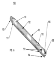
開示された髄内釘は軸部を備え、軸部は、ある長さと、一定の直径と、外側骨接触面とを有する。釘は、さらに、前(または遠位)端及び後(または近位)端を含む。先端は、挿入を容易にするために次第に先細りになっており、非侵襲的な設計であり、標準K-ワイヤの先端を受け入れるようになっているウェル(well)またはカップを備える。先端のウェルまたはカップは、必要に応じて、取り外しツールと噛み合うようになっている雌ねじ部を備えてもよい。後端は、準備された骨に釘を挿入するための駆動ツールに取り付けられるようになっている駆動取付部を備える。後端は、必要に応じて、挿入ハンドルとしても機能することができるドリルガイドに釘を固定するために使用することができる雌ねじ部を含んでもよい。釘の軸部には、必要に応じて、釘が所望のように配置された場合に、圧縮ロックねじ及び貫通ねじをそれぞれ挿入するためのねじ付き及び/又はねじなしの交差穿孔が設けられていてもよい。 The disclosed intramedullary nail comprises a shank having a length, a diameter, and an outer bone contact surface. The nail further comprises an anterior (or distal) end and a posterior (or proximal) end. The tip is tapered to facilitate insertion, is of a non-invasive design, and comprises a well or cup adapted to receive the tip of a standard K-wire. The well or cup at the tip may optionally comprise an internal thread adapted to mate with a removal tool. The posterior end comprises a drive attachment adapted to be attached to a drive tool for inserting the nail into the prepared bone. The posterior end may optionally include an internal thread that can be used to secure the nail to a drill guide that may also function as an insertion handle. The shank of the nail may optionally be provided with threaded and/or non-threaded cross-bores for inserting a compression locking screw and a through screw, respectively, once the nail is positioned as desired.
図1A~図1Bを参照すると、本発明の一実施形態に係る髄内釘(100)のいくつかの図が示されている。髄内釘(100)は長尺状の軸部(101)を備え、軸部(101)は、外側骨接触面(102)と、前(または遠位)端(103)と、後(または近位)端(104)とを有する。 1A-1B, several views of an intramedullary nail (100) according to one embodiment of the present invention are shown. The intramedullary nail (100) comprises an elongated shank (101) having an outer bone-contacting surface (102), an anterior (or distal) end (103), and a posterior (or proximal) end (104).
後端(104)は、雌ねじ部(105)と回転防止特徴部(106)とを備え、回転防止特徴部(106)は、ドリルガイド/挿入ハンドル兼用器具(200)(図3A~3B参照)の対応する特徴部(204)と噛み合うようになっている。雌ねじ部は、ロックねじ(300)の対応するねじ付き先端(303)と噛み合うようになっている(図4参照)。 The rear end (104) includes internal threads (105) and an anti-rotation feature (106) that is adapted to mate with a corresponding feature (204) on the combination drill guide/insertion handle instrument (200) (see FIGS. 3A-3B). The internal threads are adapted to mate with a corresponding threaded tip (303) on the locking screw (300) (see FIG. 4).
先端(103)は、骨への挿入時にK-ワイヤの先端を受け入れるようになっているウェルまたはカップ(107)を含む。また、先端は、必要に応じて、いったん挿入されると、髄内釘(100)を骨から押し出すのではなく引っぱるために利用され得る取り外しツール(図示せず)と噛み合うようになっている雌ねじ部(109)を含んでもよい。ロックねじ(300)(図4参照)は、必要に応じて、取り外しツールとして機能してもよい。また、先端(103)は、必要に応じて、骨への釘の挿入を容易にするために、テーパ状の先端(108)を含んでもよい(図1A、図1B参照)。 The tip (103) includes a well or cup (107) adapted to receive the tip of the K-wire during insertion into the bone. The tip may also optionally include female threads (109) adapted to mate with a removal tool (not shown) that may be utilized to pull, rather than push, the intramedullary nail (100) out of the bone once inserted. The locking screw (300) (see FIG. 4) may optionally function as a removal tool. The tip (103) may also optionally include a tapered tip (108) (see FIGS. 1A and 1B) to facilitate insertion of the nail into the bone.
また、長尺状の軸部(101)は、ロックねじ(図示せず)を挿入するためのねじ付きまたはねじなしの交差穿孔(110,111)を含んでもよい。
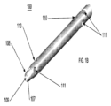
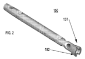
図2に示される髄内釘(150)の別の実施形態では、後端(151)は、必要に応じて、さらなる強度を提供するために、また、より直径の小さい髄内釘の場合にドリルガイド/挿入ハンドル兼用器具(200)(図3B参照)の噛み合い特徴部(204)との適切な噛み合いを確実に行うために、拡径部(152)を含んでもよい。
The elongated shaft (101) may also include threaded or unthreaded cross-bores (110, 111) for insertion of locking screws (not shown).
In another embodiment of the intramedullary nail (150) shown in FIG. 2, the rear end (151) may include an enlarged diameter portion (152) to provide additional strength, if desired, and to ensure proper engagement with the mating feature (204) of the combination drill guide/insertion handle instrument (200) (see FIG. 3B) for smaller diameter intramedullary nails.
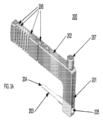
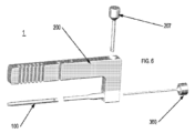
次に図3Aを参照すると、本発明の一実施形態に係るドリルガイド/挿入ハンドル兼用器具(200)(combination drill guide/insertion handle)の図がいくつか示されている。ドリルガイド/挿入ハンドル兼用器具(200)は、垂直ハンドル部(201)と水平ドリルガイド部(202)とを備えた略L字形である。垂直ハンドル部(201)とドリルガイド部(202)とは、一体構造になっていてもよいし、ドリルガイド/挿入ハンドル兼用器具を形成するために一緒に組み立てられる2以上の構成要素を含んでもよい。垂直ハンドル部(202)の底部には、水平マンドレル(203)があり、このマンドレルは、必要に応じて、その先端(204)に向かって部分的に、又は完全に、テーパ状になっていてもよい。マンドレル(203)の先端(204)は、髄内釘(100)の回転防止特徴部(106)と噛み合うようになっている(図1A参照)。 3A, there are shown several views of a combination drill guide/insertion handle (200) according to one embodiment of the present invention. The combination drill guide/insertion handle (200) is generally L-shaped with a vertical handle portion (201) and a horizontal drill guide portion (202). The vertical handle portion (201) and the drill guide portion (202) may be of unitary construction or may include two or more components assembled together to form the combination drill guide/insertion handle. At the bottom of the vertical handle portion (202) is a horizontal mandrel (203), which may be partially or fully tapered to its tip (204) as desired. The tip (204) of the mandrel (203) is adapted to mate with the anti-rotation feature (106) of the intramedullary nail (100) (see FIG. 1A).
ドリルガイド/挿入ハンドル兼用器具(200)は、さらに、垂直ハンドル(201)の後部から延びて、マンドレル(203)を通るとともにマンドレル(203)の先端(204)を通る、オリフィス(205)を備える。オリフィス(205)は、髄内釘(100)をドリルガイド/挿入ハンドル兼用器具(200)に固定するために、ロックねじ(300)(図4参照)を受け入れるようになっている。 The combination drill guide and insertion handle instrument (200) further includes an orifice (205) extending from the rear of the vertical handle (201) through the mandrel (203) and through the tip (204) of the mandrel (203). The orifice (205) is adapted to receive a locking screw (300) (see FIG. 4) for securing the intramedullary nail (100) to the combination drill guide and insertion handle instrument (200).
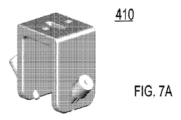
また、ドリルガイド/挿入ハンドル兼用器具(200)は、1以上のドリルスロット(206)を含む。髄内釘(100)がロックねじ(300)でマンドレルの先端(204)に取り付けられると、ドリルガイド/挿入ハンドルの1以上のドリルスロットが、髄内釘の1以上の対応する圧縮ロックねじ孔(110、図1A)と位置合わせされる。したがって、ドリルスロットは、ねじ付き垂直孔(110)(図1A、図1B、及び図8を参照)と噛み合う圧縮ロックねじのための開口部を骨に正確にあけるために使用される。ドリルガイド/挿入ハンドル兼用器具(200)に取り付けることができる追加のドリルガイド(410)を使用して、同様に、貫通ねじ孔(111)と位置合わせして、髄内釘に斜めにまたは交差方向に配向された貫通ねじ用の開口部を正確に骨にあけることができる。このようなガイドの例を図7A及び図7Bに示し、最終結果を図8A、図8B及び図8Cに示す。 The combined drill guide/insertion handle instrument (200) also includes one or more drill slots (206). When the intramedullary nail (100) is attached to the mandrel tip (204) with the locking screw (300), the one or more drill slots of the drill guide/insertion handle are aligned with one or more corresponding compression locking screw holes (110, FIG. 1A) of the intramedullary nail. The drill slots are thus used to precisely drill openings in the bone for the compression locking screws that mate with the threaded vertical holes (110) (see FIGS. 1A, 1B, and 8). An additional drill guide (410) that can be attached to the combined drill guide/insertion handle instrument (200) can be used to precisely drill openings in the bone for the through screws that are oriented obliquely or transversely to the intramedullary nail in a similar manner, aligned with the through screw holes (111). Examples of such guides are shown in FIGS. 7A and 7B, and the final result is shown in FIGS. 8A, 8B, and 8C.
ドリルガイド/挿入ハンドル兼用器具(200)は、単一の構成要素として製造されてもよいし、ドリルガイド部を挿入ハンドルから分離するためにモジュール式であってもよい。装置が2つの別個の部品として製造される場合、ドリルガイド及び挿入ハンドルは、オプションの頂部連結ねじ(207)を含む種々の手段を介して互いにロック及びロック解除され得る。 The combination drill guide/insertion handle instrument (200) may be manufactured as a single component or may be modular to separate the drill guide portion from the insertion handle. If the device is manufactured as two separate pieces, the drill guide and insertion handle may be locked and unlocked from one another via a variety of means, including an optional top interlocking screw (207).
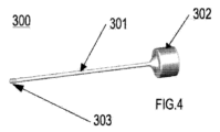
次に図4を参照すると、図5及び図6に示すように、髄内釘(100)をドリルガイド/挿入ハンドル兼用器具(200)でロックするロックねじ(300)が示されている。
連結ねじ(300)は、ノブ(302)から連結ねじの先端(303)まで延びる長尺状の軸部(301)を備える。ノブ(302)は、必要に応じて、指での回転を容易にするためにローレット加工されていてもよい。あるいは、ノブ(302)の代わりに、連結ねじを駆動ツール(図示せず)によってさらに締め付けることができる。ロックねじの先端(303)は、髄内釘(100)の後端(104)の雌ねじ部(105)と噛み合うようになっている雄ねじ部を備え、この雄ねじ部は、必要に応じて、髄内釘(100)の前端(103)の雌ねじ部(109)とも嵌合するようになっている。
4, there is shown a locking screw (300) for locking the intramedullary nail (100) with the combined drill guide/insertion handle instrument (200), as shown in FIGS.
The locking screw (300) has an elongated shank (301) that extends from a knob (302) to the tip (303) of the locking screw. The knob (302) may be knurled to facilitate finger rotation, if desired. Alternatively, instead of the knob (302), the locking screw may be further tightened by a driving tool (not shown). The tip (303) of the locking screw has male threads that are adapted to mate with the female threads (105) at the rear end (104) of the nail (100) and, if desired, also mate with the female threads (109) at the front end (103) of the nail (100).
次に図5及び図6を参照すると、さらに、髄内釘(100)、ドリルガイド/挿入ハンドル兼用器具(200)及び連結ねじ(300)がどのように噛み合うように設計されているかを示す、完全な髄内釘システム組立体(1)の組立図及び分解図が示されている。前述のように、頂部連結ねじ(207)はオプションであり、ドリルガイド/挿入ハンドル兼用器具(200)が一体構造である実施形態では不要である。 5 and 6, there are shown assembled and exploded views of the complete intramedullary nail system assembly (1), further illustrating how the intramedullary nail (100), the combination drill guide/insertion handle instrument (200), and the interlocking screw (300) are designed to mate together. As previously mentioned, the apical interlocking screw (207) is optional and not required in embodiments where the combination drill guide/insertion handle instrument (200) is of one-piece construction.
図8A、図8B、図8Cは、異なるタイプのねじを使用して中手骨及び指骨に埋め込まれた本発明の髄内釘の実施形態の例を示す。
使用方法
開示された髄内釘の挿入のための例示的な手順は、一般に、以下の工程から構成される(ここで参照される寸法は、直径4.0mmの釘のためのものであり、異なるサイズの釘に対する制限と考えるべきではない)。
8A, 8B and 8C show examples of embodiments of the intramedullary nail of the present invention implanted into the metacarpal and phalangeal bones using different types of screws.
Method of Use An exemplary procedure for insertion of the disclosed intramedullary nail generally consists of the following steps (dimensions referenced herein are for a 4.0 mm diameter nail and should not be considered a limitation for nails of different sizes):
(1)長さ20.32センチ(8インチ)、1.6mmのK-ワイヤを骨の髄内管を通じて挿入し、骨折の遠位断片及び近位断片を整列させながら治療する。これにより、釘が骨管内の中央に配置される。K-ワイヤの両端は、骨及び軟部組織の長さを超えて延びている必要がある。 (1) An 8 inch long, 1.6 mm K-wire is inserted through the intramedullary canal of the bone to align and heal the distal and proximal fragments of the fracture. This centers the nail within the bone canal. Both ends of the K-wire should extend beyond the length of the bone and soft tissue.
(2)K-ワイヤを所定の位置に維持した状態で、まず始めは、カニューレ付き突き錐で1.6mmのK-ワイヤ上をリーミングし、骨の底部の皮質骨を通過する。そして、2.7mmのカニューレ付きリーマーで、近位から遠位まで埋め込む釘の遠位端の予定位置までリーミングする。 (2) With the K-wire held in place, first ream over the 1.6 mm K-wire with a cannulated awl through the cortical bone at the base of the bone. Then ream from proximal to distal with a 2.7 mm cannulated reamer to the intended location of the distal end of the nail to be implanted.
(3)2.7mmのカニューレ付リーマーでリーミングした後、2.7mmのリーマーと同じ位置まで、次の3.3mmのリーマーでリーミングを続ける。リーマーのサイズが3.3mmで十分な場合は、3.0mmの釘を選択する。しかし、もし3.3mmのリーマーが骨の髄管に十分でない場合には、続いて3.5mmの釘または4.0mmの釘のいずれのために、それぞれ3.8mm及び4.3mmのカニューレ付きリーマーでリーミングする。 (3) After reaming with a 2.7 mm cannulated reamer, continue reaming with a 3.3 mm reamer to the same position as the 2.7 mm reamer. If the reamer size is sufficient with 3.3 mm, select a 3.0 mm nail. However, if the 3.3 mm reamer is not sufficient for the medullary canal of the bone, continue reaming with a 3.8 mm and 4.3 mm cannulated reamer for either a 3.5 mm nail or a 4.0 mm nail, respectively.
(4)釘の近位端にあるねじ山と噛み合うロックねじを使用して、釘をドリルガイド/挿入ハンドル兼用器具に取り付ける。
(5)釘の遠位端にあるウェルまたはカップを、骨の髄管内に挿入されたままのK-ワイヤの先端と噛み合わせる。釘が挿入されると、釘が骨の中に配置されると同時に1.6mmのK-ワイヤを押し出す。
(4) The nail is attached to the combined drill guide/insertion handle instrument using a locking screw that engages with the threads on the proximal end of the nail.
(5) The well or cup at the distal end of the nail is engaged with the tip of the K-wire that remains inserted into the medullary canal of the bone. Once the nail is inserted, the 1.6 mm K-wire is pushed out as the nail is positioned into the bone.
(6)釘が骨内の最終的な位置まで挿入されたら、1.4mmのK-ワイヤを使用して釘の圧縮ロックねじ孔を通じて骨に垂直孔を開ける。この際、ドリルガイド/挿入ハンドル兼用器具に刻印されたドリルガイド位置(図示略)(釘の長手方向における近位と遠位)を使用する。1.4mmのK-ワイヤは、皮質近くから延びて骨を貫通し、釘の軸部にあいた複数の垂直孔のうちの1つを通って、骨の遠い方の皮質まで延びるようにしておく。 (6) Once the nail is inserted to its final position in the bone, a 1.4 mm K-wire is used to drill a vertical hole through the compression locking screw hole in the nail, using the drill guide locations (not shown) (proximal and distal along the length of the nail) marked on the combined drill guide/insertion handle. The 1.4 mm K-wire is extended from the proximal cortex through the bone and through one of the vertical holes in the nail shaft to the distal cortex of the bone.
(7)適切なサイズの圧縮ロックねじを穿孔された交差孔に挿入し、ねじを締めて釘を所定の位置にロックする。
(8)必要に応じて、他のマークされた穿孔ガイドアダプタ位置(図示せず)を使用して、45°及び90°に配向された交差孔を穿孔して、追加のねじを挿入するようにしてもよい。
(7) Insert the appropriate size compression locking screw into the drilled cross hole and tighten the screw to lock the nail in place.
(8) If desired, other marked drill guide adapter positions (not shown) may be used to drill cross holes oriented at 45° and 90° to insert additional screws.
上記では、特定の骨の形状、釘の直径、及びねじのタイプに関して説明したが、これらの説明は、本発明の思想から逸脱することなく、また説明された実施形態と均等な範囲内で様々な修正がなされ得るものであり、説明した実施系阿智に限定することを意図するものではない。
[例1]
軸部であって、第1端及びその反対側の第2端と、ある長さと、ある直径と、外側骨接触面とを有する、軸部と、
前記第1端に隣接する先端であって、前記第1端から次第に先細りになってカップ内で終端する、先端と、
前記第2端に隣接する後端であって、駆動ツールに取り付けられるようになっている取付部で終端する、後端と、
を備え、
前記軸部、前記先端、及び前記後端は、骨の髄質に挿入されるようになっている、髄内釘。
[例2]
前記先端の前記カップが、K-ワイヤの先端を受け入れるようになっている、
上記例1に記載の髄内釘。
[例3]
前記先端の前記カップが、雌ねじ部をさらに含む、
上記例1に記載の髄内釘。
[例4]
前記先端の前記カップの前記雌ねじ部が、雄ねじが切られた取り外しツールと噛み合うようになっている、
上記例3に記載の髄内釘。
[例5]
前記後端が、雌ねじ部をさらに含む、
上記例1に記載の髄内釘。
[例6]
前記後端の前記雌ねじ部は、雄ねじが切られた挿入ハンドルと噛み合うようになっている、
上記例5に記載の髄内釘。
[例7]
前記軸部が、1以上の交差穿孔をさらに含む、
上記例1に記載の髄内釘。
[例8]
前記1以上の交差穿孔のうちの少なくとも1つは、少なくとも部分的にねじが切られている、
上記例7に記載の髄内釘。
[例9]
前記1以上の交差穿孔のうちの少なくとも1つは、ねじが切られていない、
上記例7に記載の髄内釘。
Although the above describes specific bone shapes, nail diameters, and screw types, these descriptions are not intended to be limited to the described embodiments, as various modifications may be made without departing from the spirit of the invention and within the scope of equivalents to the described embodiments.
[Example 1]
a shank having a first end and an opposing second end, a length, a diameter, and an outer bone contacting surface;
a tip adjacent the first end, the tip gradually tapering from the first end to terminate within a cup;
a rear end adjacent the second end and terminating in a mounting portion adapted to be attached to a driving tool;
Equipped with
The shank, the tip, and the rear end are adapted to be inserted into the medullary tissue of a bone.
[Example 2]
the cup at the tip is adapted to receive the tip of a K-wire;
The intramedullary nail described in Example 1 above.
[Example 3]
the cup at the tip further includes an internal thread;
The intramedullary nail described in Example 1 above.
[Example 4]
the female threads of the tip cup are adapted to mate with a male threaded removal tool;
The intramedullary nail described in Example 3 above.
[Example 5]
The rear end further includes an internal thread portion.
The intramedullary nail described in Example 1 above.
[Example 6]
The female threads at the rear end are adapted to mate with an externally threaded insertion handle.
The intramedullary nail described in Example 5 above.
[Example 7]
the shaft further comprising one or more cross-drillings.
The intramedullary nail described in Example 1 above.
[Example 8]
At least one of the one or more cross-bores is at least partially threaded.
The intramedullary nail described in Example 7 above.
[Example 9]
At least one of the one or more cross-bores is non-threaded.
The intramedullary nail described in Example 7 above.
Claims (12)
骨に前記髄内釘を挿入するための駆動ツールと、
前記髄内釘を前記骨に挿入するためのガイドとしてのK-ワイヤと、を備え、
前記髄内釘は、
軸部であって、軸方向における第1端及びその反対側の第2端と、前記軸方向におけるある長さと、ある直径と、前記第1端から前記第2端まで延びる、前記軸部の外周面である外側骨接触面とを有する、軸部と、
前記第1端に隣接する先端部であって、前記第1端に開口するように凹設されたカップを有し、前記カップの内周面は前記第1端からその内底部まで前記軸方向に沿って延びている、先端部と、
前記第2端に隣接する後端部であって、前記第2端に向けて拡径した拡径部と、前記駆動ツールに取り付けられるようになっている取付部とを有して、前記取付部で終端する、後端部と、
を備え、
前記軸部の直径は前記先端部から前記第1端に向けて次第に減少しており、
前記取付部が雌ねじ部を含み、前記駆動ツールが前記雌ねじ部と噛み合うように適合された雄ねじ部を有し、
前記カップが、K-ワイヤの先端と着脱可能に噛み合うようになっており、
前記軸部、前記先端部、及び前記後端部を含む前記髄内釘は、前記カップに噛み合った前記K-ワイヤに案内されるとともに前記取付部に取りつけられた前記駆動ツールに押されることにより、前記骨の髄質に挿入されるようになっている、髄内釘システム。 Intramedullary nails and
a driving tool for inserting the nail into bone;
a K-wire as a guide for inserting the intramedullary nail into the bone;
The intramedullary nail comprises:
a shaft portion having a first end and an opposite second end in an axial direction, a length in the axial direction, a diameter, and an outer bone contact surface that is an outer peripheral surface of the shaft portion and extends from the first end to the second end;
a tip portion adjacent to the first end, the tip portion having a cup recessed to open into the first end, the inner circumferential surface of the cup extending along the axial direction from the first end to an inner bottom portion thereof;
a rear end adjacent the second end, the rear end having an enlarged diameter portion that enlarges toward the second end and an attachment portion adapted to be attached to the driving tool and terminating in the attachment portion;
Equipped with
The diameter of the shaft portion gradually decreases from the tip portion to the first end,
the mounting portion includes an internally threaded portion, the driving tool having an externally threaded portion adapted to mate with the internally threaded portion;
The cup is adapted to releasably engage the distal end of the K-wire;
The intramedullary nail system includes an intramedullary nail including the shaft portion, the tip portion, and the rear end portion, which is adapted to be inserted into the medullary tissue of the bone by being guided by the K-wire engaged with the cup and pushed by the driving tool attached to the attachment portion.
骨に前記髄内釘を挿入するための駆動ツールと、
前記髄内釘を前記骨に挿入するためのガイドとしてのK-ワイヤと、を備え、
前記髄内釘は、
軸部であって、軸方向における第1端及びその反対側の第2端と、前記軸方向におけるある長さと、ある直径と、前記第1端から前記第2端まで延びる、前記軸部の外周面である外側骨接触面と、前記軸方向に対して斜めに又は交差方向に延びるように交差穿孔された1以上の孔と、を有する、軸部と、
前記第1端に隣接する先端部であって、前記第1端に開口するように凹設されたカップを有し、前記カップの内周面は前記第1端からその内底部まで前記軸方向に沿って延びている、先端部と、
前記第2端に隣接する後端部であって、前記駆動ツールに取り付けられるようになっている取付部を有して、前記取付部で終端する、後端部と、
を備え、
前記軸部の直径は前記先端部から前記第1端に向けて次第に減少しており、
前記取付部が雌ねじ部を含み、前記駆動ツールが前記雌ねじ部と噛み合うように適合された雄ねじ部を有し、
前記カップが、K-ワイヤの先端と着脱可能に噛み合うようになっており、
前記軸部、前記先端部、及び前記後端部を含む前記髄内釘は、前記カップに噛み合った前記K-ワイヤに案内されるとともに前記取付部に取りつけられた前記駆動ツールに押されることにより、前記骨の髄質に挿入されるようになっており、
前記1以上の孔のうちの少なくとも1つは、ねじが切られていない、髄内釘システム。 Intramedullary nails and
a driving tool for inserting the nail into bone;
a K-wire as a guide for inserting the intramedullary nail into the bone;
The intramedullary nail comprises:
a shaft portion having a first end and an opposite second end in an axial direction, a length in the axial direction, a diameter, an outer bone contacting surface that is an outer peripheral surface of the shaft portion extending from the first end to the second end, and one or more cross-drilled holes that extend obliquely or transversely to the axial direction ;
a tip portion adjacent to the first end, the tip portion having a cup recessed to open into the first end, the inner circumferential surface of the cup extending along the axial direction from the first end to an inner bottom portion thereof;
a rear end adjacent the second end, the rear end having and terminating in a mounting portion adapted to be attached to the driving tool;
Equipped with
The diameter of the shaft portion gradually decreases from the tip portion to the first end,
the mounting portion includes an internally threaded portion, the driving tool having an externally threaded portion adapted to mate with the internally threaded portion;
The cup is adapted to releasably engage the distal end of the K-wire;
the nail including the shank, the tip, and the rear end is adapted to be inserted into the medulla of the bone by being guided by the K-wire engaged with the cup and pushed by the driving tool attached to the attachment portion ;
An intramedullary nail system , wherein at least one of the one or more holes is non-threaded .
請求項1又は2に記載の髄内釘システム。 the cup of the tip is adapted to receive the tip of the K-wire, the inner diameter of the cup being larger than the diameter of the K-wire so that the tip of the K-wire fits within the cup of the nail;
3. The intramedullary nail system according to claim 1 or 2 .
請求項1又は2に記載の髄内釘システム。 The cup at the tip further includes an internal thread.
3. The intramedullary nail system according to claim 1 or 2 .
請求項1に記載の髄内釘システム。 the shaft portion further includes one or more cross-drilled holes extending obliquely or transversely to the axial direction;
The intramedullary nail system of claim 1.
請求項2又は5に記載の髄内釘システム。 At least one of the one or more holes is at least partially threaded.
6. The intramedullary nail system according to claim 2 or 5 .
請求項5に記載の髄内釘システム。 At least one of the one or more holes is unthreaded.
The intramedullary nail system of claim 5 .
請求項2に記載の髄内釘システム。 The rear end portion includes an expanded diameter portion.
The intramedullary nail system of claim 2 .
前記取り外しツールはロックねじであり、前記ロックねじは、前記カップに挿入された場合に前記カップの前記雌ねじ部と噛み合うように適合されたねじ付き先端を有する、
請求項4に記載の髄内釘システム。 a removal tool for removing the intramedullary nail from a bone,
the removal tool being a locking screw having a threaded tip adapted to mate with the internal threads of the cup when inserted into the cup;
The intramedullary nail system of claim 4 .
前記挿入ハンドルは、前記髄内釘の前記取付部の前記雌ねじ部と噛み合うように適合される雄ねじを有する、
請求項1~8のうち何れか一項に記載の髄内釘システム。 an insertion handle for inserting the intramedullary nail into a bone;
the insertion handle having external threads adapted to mate with the internal threads of the attachment portion of the intramedullary nail;
An intramedullary nail system according to any one of claims 1 to 8 .
前記髄内釘は、前記取付部の前記雌ねじ部を介して前記マンドレルの先端に取りつけられるように適合される、
請求項10に記載の髄内釘システム。 the insertion handle having a handle portion and a mandrel protruding from the handle portion;
the nail is adapted to be attached to the distal end of the mandrel via the female threads of the attachment portion;
The intramedullary nail system of claim 10.
前記マンドレルの前記先端は前記凹部と係合するように適合された凸部を有する、
請求項11に記載の髄内釘システム。 the mounting portion includes an anti-rotation feature, the anti-rotation feature being a recess formed in the second end;
the tip of the mandrel has a protrusion adapted to engage the recess;
The intramedullary nail system of claim 11.
Priority Applications (1)
| Application Number | Priority Date | Filing Date | Title |
|---|---|---|---|
| JP2024190600A JP2025003736A (en) | 2019-10-25 | 2024-10-30 | Intramedullary nail and method of using same |
Applications Claiming Priority (3)
| Application Number | Priority Date | Filing Date | Title |
|---|---|---|---|
| US201962926156P | 2019-10-25 | 2019-10-25 | |
| US62/926,156 | 2019-10-25 | ||
| PCT/US2020/056799 WO2021081168A1 (en) | 2019-10-25 | 2020-10-22 | Intramedullary fixation nail and method of use |
Related Child Applications (1)
| Application Number | Title | Priority Date | Filing Date |
|---|---|---|---|
| JP2024190600A Division JP2025003736A (en) | 2019-10-25 | 2024-10-30 | Intramedullary nail and method of using same |
Publications (3)
| Publication Number | Publication Date |
|---|---|
| JP2022553003A JP2022553003A (en) | 2022-12-21 |
| JP2022553003A5 JP2022553003A5 (en) | 2023-07-28 |
| JP7581344B2 true JP7581344B2 (en) | 2024-11-12 |
Family
ID=75585309
Family Applications (2)
| Application Number | Title | Priority Date | Filing Date |
|---|---|---|---|
| JP2022522971A Active JP7581344B2 (en) | 2019-10-25 | 2020-10-22 | Intramedullary nail and method of using same |
| JP2024190600A Pending JP2025003736A (en) | 2019-10-25 | 2024-10-30 | Intramedullary nail and method of using same |
Family Applications After (1)
| Application Number | Title | Priority Date | Filing Date |
|---|---|---|---|
| JP2024190600A Pending JP2025003736A (en) | 2019-10-25 | 2024-10-30 | Intramedullary nail and method of using same |
Country Status (7)
| Country | Link |
|---|---|
| US (2) | US11344341B2 (en) |
| EP (1) | EP4048170B1 (en) |
| JP (2) | JP7581344B2 (en) |
| AU (1) | AU2020370260B2 (en) |
| CA (1) | CA3157341C (en) |
| ES (1) | ES3030866T3 (en) |
| WO (1) | WO2021081168A1 (en) |
Families Citing this family (4)
| Publication number | Priority date | Publication date | Assignee | Title |
|---|---|---|---|---|
| US12458406B2 (en) | 2020-04-09 | 2025-11-04 | Wright Medical Technology, Inc. | Jigs, systems, and methods for correcting joint deformities |
| USD935613S1 (en) * | 2020-05-29 | 2021-11-09 | Brent Austin McNeely | Intramedullary cement spacer mold system |
| US20230031466A1 (en) * | 2021-07-29 | 2023-02-02 | Trimed, Incorporated | Bone implant and method of controlling the bone implant |
| US12349947B2 (en) * | 2021-10-14 | 2025-07-08 | Western Washington University | Distal-screw guiding system for interlocking intramedullary nail implants |
Citations (7)
| Publication number | Priority date | Publication date | Assignee | Title |
|---|---|---|---|---|
| US20020156473A1 (en) | 2001-04-24 | 2002-10-24 | Bramlet Dale G. | Intramedullary hip nail with bifurcated lock |
| US20070156144A1 (en) | 2004-06-24 | 2007-07-05 | Dieter Ulrich | Intramedullary nail |
| US20080221574A1 (en) | 2007-03-05 | 2008-09-11 | Cesare Cavallazzi | Method of Treating a Clavicle Fracture |
| US20140088595A1 (en) | 2011-02-08 | 2014-03-27 | Stryker Trauma Gmbh | Implant system for bone fixation |
| US20140188113A1 (en) | 2010-09-09 | 2014-07-03 | DePuy Synthes Products, LLC | Surgical nail |
| US20160206355A1 (en) | 2013-09-06 | 2016-07-21 | Cristobal ROBLEDO | Distal locking intramedullary nail |
| US20190175232A1 (en) | 2017-12-13 | 2019-06-13 | DePuy Synthes Products, Inc. | Intramedullary nail with cannulation access hole |
Family Cites Families (4)
| Publication number | Priority date | Publication date | Assignee | Title |
|---|---|---|---|---|
| IL48826A (en) * | 1976-01-13 | 1978-08-31 | Aginsky Yacov | Intramedullary compression nail for the treatment of bone fractures |
| US4875474A (en) | 1988-01-29 | 1989-10-24 | Biomet, Inc. | Variable wall thickness interlocking intramedullary nail |
| DE9109883U1 (en) * | 1991-08-09 | 1991-09-26 | Howmedica GmbH, 2314 Schönkirchen | Locking nail for the treatment of femoral fractures in the middle and trochanteric region |
| WO1998002104A1 (en) * | 1996-07-16 | 1998-01-22 | Philippe Vichard | Ascending centromedullary thigh bone pin with mechanical clamping of its two ends |
-
2020
- 2020-10-21 US US17/076,661 patent/US11344341B2/en active Active
- 2020-10-22 CA CA3157341A patent/CA3157341C/en active Active
- 2020-10-22 ES ES20878700T patent/ES3030866T3/en active Active
- 2020-10-22 WO PCT/US2020/056799 patent/WO2021081168A1/en not_active Ceased
- 2020-10-22 JP JP2022522971A patent/JP7581344B2/en active Active
- 2020-10-22 AU AU2020370260A patent/AU2020370260B2/en active Active
- 2020-10-22 EP EP20878700.2A patent/EP4048170B1/en active Active
-
2022
- 2022-05-27 US US17/804,433 patent/US12102359B2/en active Active
-
2024
- 2024-10-30 JP JP2024190600A patent/JP2025003736A/en active Pending
Patent Citations (7)
| Publication number | Priority date | Publication date | Assignee | Title |
|---|---|---|---|---|
| US20020156473A1 (en) | 2001-04-24 | 2002-10-24 | Bramlet Dale G. | Intramedullary hip nail with bifurcated lock |
| US20070156144A1 (en) | 2004-06-24 | 2007-07-05 | Dieter Ulrich | Intramedullary nail |
| US20080221574A1 (en) | 2007-03-05 | 2008-09-11 | Cesare Cavallazzi | Method of Treating a Clavicle Fracture |
| US20140188113A1 (en) | 2010-09-09 | 2014-07-03 | DePuy Synthes Products, LLC | Surgical nail |
| US20140088595A1 (en) | 2011-02-08 | 2014-03-27 | Stryker Trauma Gmbh | Implant system for bone fixation |
| US20160206355A1 (en) | 2013-09-06 | 2016-07-21 | Cristobal ROBLEDO | Distal locking intramedullary nail |
| US20190175232A1 (en) | 2017-12-13 | 2019-06-13 | DePuy Synthes Products, Inc. | Intramedullary nail with cannulation access hole |
Also Published As
| Publication number | Publication date |
|---|---|
| US11344341B2 (en) | 2022-05-31 |
| WO2021081168A1 (en) | 2021-04-29 |
| ES3030866T3 (en) | 2025-07-02 |
| JP2025003736A (en) | 2025-01-09 |
| AU2020370260A1 (en) | 2022-04-21 |
| US20210121209A1 (en) | 2021-04-29 |
| US12102359B2 (en) | 2024-10-01 |
| CA3157341C (en) | 2024-01-30 |
| JP2022553003A (en) | 2022-12-21 |
| US20220287743A1 (en) | 2022-09-15 |
| EP4048170B1 (en) | 2025-04-23 |
| EP4048170A4 (en) | 2023-11-29 |
| AU2020370260B2 (en) | 2024-11-14 |
| EP4048170A1 (en) | 2022-08-31 |
| CA3157341A1 (en) | 2021-04-29 |
Similar Documents
| Publication | Publication Date | Title |
|---|---|---|
| JP7581344B2 (en) | Intramedullary nail and method of using same | |
| US8663224B2 (en) | Surgical nail | |
| US8353910B2 (en) | Hip helical implant | |
| KR100904142B1 (en) | Intramedullary fixation assembly and devices and methods for installing the same | |
| EP1824401A4 (en) | BONE-SCREW PLATE WITH PRE-ASSEMBLED DRILLING GUIDE ENDS | |
| EP3484388A1 (en) | Intramedullary implant with proximal plate and method for its use | |
| US20250160918A1 (en) | Targeting guide | |
| US9510841B2 (en) | Drill bit and method for preparing a bone for a fixation screw | |
| EP3232961A1 (en) | Active fracture compression implants | |
| WO2004073544A2 (en) | Cannulated drill pin | |
| TW201345479A (en) | Self centering feature for an intramedullary nail | |
| CN107223040A (en) | Medullary fixation device and system in hipbone and femoral fracture operation | |
| US7141052B2 (en) | Surgical intramedullary implant with improved locking for fixation of fractured bone segments | |
| US8187276B1 (en) | Odd angle internal bone fixation device for use in a transverse fracture of a humerus | |
| US20250177016A1 (en) | Telescopic intramedullary nail and kit comprising said telescopic intramedullary nail and corresponding tools | |
| US12232749B2 (en) | Drill guide for orthopedic device | |
| US20230277197A1 (en) | Low profile drill and/or k-wire guide and method for use thereof | |
| US20050107793A1 (en) | Surgical intramedullary implant with improved locking for fixation of fractured bone segments |
Legal Events
| Date | Code | Title | Description |
|---|---|---|---|
| A521 | Request for written amendment filed |
Free format text: JAPANESE INTERMEDIATE CODE: A523 Effective date: 20230720 |
|
| A621 | Written request for application examination |
Free format text: JAPANESE INTERMEDIATE CODE: A621 Effective date: 20230720 |
|
| A977 | Report on retrieval |
Free format text: JAPANESE INTERMEDIATE CODE: A971007 Effective date: 20240222 |
|
| A131 | Notification of reasons for refusal |
Free format text: JAPANESE INTERMEDIATE CODE: A131 Effective date: 20240227 |
|
| A521 | Request for written amendment filed |
Free format text: JAPANESE INTERMEDIATE CODE: A523 Effective date: 20240527 |
|
| A131 | Notification of reasons for refusal |
Free format text: JAPANESE INTERMEDIATE CODE: A131 Effective date: 20240709 |
|
| A521 | Request for written amendment filed |
Free format text: JAPANESE INTERMEDIATE CODE: A523 Effective date: 20240927 |
|
| TRDD | Decision of grant or rejection written | ||
| A01 | Written decision to grant a patent or to grant a registration (utility model) |
Free format text: JAPANESE INTERMEDIATE CODE: A01 Effective date: 20241015 |
|
| A61 | First payment of annual fees (during grant procedure) |
Free format text: JAPANESE INTERMEDIATE CODE: A61 Effective date: 20241030 |
|
| R150 | Certificate of patent or registration of utility model |
Ref document number: 7581344 Country of ref document: JP Free format text: JAPANESE INTERMEDIATE CODE: R150 |