JP7581342B2 - Surgical Saw Blades - Google Patents
Surgical Saw Blades Download PDFInfo
- Publication number
- JP7581342B2 JP7581342B2 JP2022522912A JP2022522912A JP7581342B2 JP 7581342 B2 JP7581342 B2 JP 7581342B2 JP 2022522912 A JP2022522912 A JP 2022522912A JP 2022522912 A JP2022522912 A JP 2022522912A JP 7581342 B2 JP7581342 B2 JP 7581342B2
- Authority
- JP
- Japan
- Prior art keywords
- saw blade
- surgical saw
- shank
- engage
- hole
- Prior art date
- Legal status (The legal status is an assumption and is not a legal conclusion. Google has not performed a legal analysis and makes no representation as to the accuracy of the status listed.)
- Active
Links
Images


Classifications
-
- A—HUMAN NECESSITIES
- A61—MEDICAL OR VETERINARY SCIENCE; HYGIENE
- A61B—DIAGNOSIS; SURGERY; IDENTIFICATION
- A61B17/00—Surgical instruments, devices or methods
- A61B17/14—Surgical saws
- A61B17/142—Surgical saws with reciprocating saw blades, e.g. with cutting edges at the distal end of the saw blades
-
- A—HUMAN NECESSITIES
- A61—MEDICAL OR VETERINARY SCIENCE; HYGIENE
- A61B—DIAGNOSIS; SURGERY; IDENTIFICATION
- A61B17/00—Surgical instruments, devices or methods
- A61B17/16—Instruments for performing osteoclasis; Drills or chisels for bones; Trepans
- A61B17/1637—Hollow drills or saws producing a curved cut, e.g. cylindrical
-
- A—HUMAN NECESSITIES
- A61—MEDICAL OR VETERINARY SCIENCE; HYGIENE
- A61B—DIAGNOSIS; SURGERY; IDENTIFICATION
- A61B17/00—Surgical instruments, devices or methods
- A61B2017/00477—Coupling
-
- A—HUMAN NECESSITIES
- A61—MEDICAL OR VETERINARY SCIENCE; HYGIENE
- A61B—DIAGNOSIS; SURGERY; IDENTIFICATION
- A61B34/00—Computer-aided surgery; Manipulators or robots specially adapted for use in surgery
- A61B34/20—Surgical navigation systems; Devices for tracking or guiding surgical instruments, e.g. for frameless stereotaxis
- A61B2034/2046—Tracking techniques
- A61B2034/2055—Optical tracking systems
-
- A—HUMAN NECESSITIES
- A61—MEDICAL OR VETERINARY SCIENCE; HYGIENE
- A61B—DIAGNOSIS; SURGERY; IDENTIFICATION
- A61B34/00—Computer-aided surgery; Manipulators or robots specially adapted for use in surgery
- A61B34/20—Surgical navigation systems; Devices for tracking or guiding surgical instruments, e.g. for frameless stereotaxis
- A61B2034/2068—Surgical navigation systems; Devices for tracking or guiding surgical instruments, e.g. for frameless stereotaxis using pointers, e.g. pointers having reference marks for determining coordinates of body points
- A61B2034/207—Divots for calibration
Landscapes
- Health & Medical Sciences (AREA)
- Surgery (AREA)
- Life Sciences & Earth Sciences (AREA)
- Heart & Thoracic Surgery (AREA)
- Molecular Biology (AREA)
- Oral & Maxillofacial Surgery (AREA)
- Engineering & Computer Science (AREA)
- Biomedical Technology (AREA)
- Dentistry (AREA)
- Medical Informatics (AREA)
- Nuclear Medicine, Radiotherapy & Molecular Imaging (AREA)
- Animal Behavior & Ethology (AREA)
- General Health & Medical Sciences (AREA)
- Public Health (AREA)
- Veterinary Medicine (AREA)
- Orthopedic Medicine & Surgery (AREA)
- Surgical Instruments (AREA)
Description
本発明は、概して、動力鋸で使用するための外科用鋸刃に関する。 The present invention relates generally to a surgical saw blade for use in a power saw.
外科用鋸は、骨の手術を行うために広く使用されている。多くのそのような鋸は、その一端に歯付きセグメントを有する細長い鋸刃を使用しており、他端で角度振動を可能にする旋回マウントを有する。角度方式で振動する刃は、刃先端において広い切断運動を提供し得る。いくつかの場合では、患者への外傷を最小限に抑えるために、最小限の切断運動が望まれ得る。 Surgical saws are widely used to perform bone surgery. Many such saws use an elongated saw blade with a toothed segment at one end and a pivoting mount at the other end that allows for angular oscillation. A blade that oscillates in an angular manner can provide a wide cutting motion at the blade tip. In some cases, a minimal cutting motion may be desired to minimize trauma to the patient.
改善された外科用鋸刃の現在の必要性に鑑みて、様々な例示的な実施形態の簡単な概要が提示される。以下の概要では、いくつかの単純化及び省略が行われることがあり、これらは、各種の例示の実施形態のいくつかの態様を強調して紹介するためである。当業者が本明細書に開示された概念を作り上げ、使用することができるようにするうえで適切な例示的実施形態の詳細な説明が、この後の各項に続く。 In light of the current need for improved surgical saw blades, a brief overview of various exemplary embodiments is presented. In the following overview, some simplifications and omissions may be made in order to highlight and introduce certain aspects of the various exemplary embodiments. Detailed descriptions of the exemplary embodiments adequate to enable one of ordinary skill in the art to make and use the concepts disclosed herein follow in the following sections.
本明細書に開示される様々な実施形態は、上面及び下面を有する外科用鋸刃に関する。鋸刃は、右側側縁部及び左側側縁部を有する第1の端部であって、第1の端部が、動力鋸の振動ヘッドに接続するように構成されている、第1の端部と、複数の歯を上に有する第2の端部と、右側側縁部及び左側側縁部を有する細長いシャンクであって、細長いシャンクが、第1の端部と第2の端部とを接続する、細長いシャンクと、を含み得る。様々な実施形態では、第1の端部は、細長いシャンクよりも狭く、停止面は、第1の端部を細長いシャンクに接続する。停止面は、振動ヘッドに対する鋸刃の正確な位置決めを確実にするように、振動ヘッドと係合するように構成され得る。 Various embodiments disclosed herein relate to a surgical saw blade having an upper surface and a lower surface. The saw blade may include a first end having right and left side edges, the first end configured to connect to an oscillating head of a power saw, a second end having a plurality of teeth thereon, and an elongated shank having right and left side edges, the elongated shank connecting the first and second ends. In various embodiments, the first end is narrower than the elongated shank, and a stop surface connects the first end to the elongated shank. The stop surface may be configured to engage the oscillating head to ensure accurate positioning of the saw blade relative to the oscillating head.
様々な実施形態では、外科用鋸刃は、鋸刃の第1の端部の右側側縁部を細長いシャンクの右側側縁部に接続する第1の停止面と、第1の端部の左側側縁部を細長いシャンクの左側側縁部に接続する第2の停止面と、を含む、停止面を有する。第1の停止面及び第2の停止面は、振動ヘッドと係合するように構成され得る。 In various embodiments, the surgical saw blade has a stop surface including a first stop surface connecting a right side edge of a first end of the saw blade to a right side edge of the elongated shank and a second stop surface connecting a left side edge of the first end of the saw blade to a left side edge of the elongated shank. The first stop surface and the second stop surface can be configured to engage the oscillating head.
様々な実施形態では、鋸刃の第1の端部は、上面及び下面を有し、第1の端部内の穴は、上面から下面まで延在する。鋸刃の第1の端部の上面及び下面は、動力鋸上の第1のクランプ及び第2のクランプ面と係合するように構成され得る。第1の端部内の穴は、第1のクランプ面及び第2のクランプ面のうちの少なくとも1つの上の上昇した隆起部と係合するように構成され得る。 In various embodiments, the first end of the saw blade has an upper surface and a lower surface, and a hole in the first end extends from the upper surface to the lower surface. The upper and lower surfaces of the first end of the saw blade can be configured to engage with a first clamp and a second clamping surface on the power saw. The hole in the first end can be configured to engage a raised ridge on at least one of the first clamping surface and the second clamping surface.
本明細書に開示される様々な実施形態は、上面及び下面を有する外科用鋸刃に関する。鋸刃は、右側側縁部及び左側側縁部を有する第1の端部であって、第1の端部が、動力鋸の振動ヘッドに接続するように構成されている、第1の端部と、複数の歯を上に有する第2の端部と、右側側縁部及び左側側縁部を有する細長いシャンクであって、細長いシャンクが、第1の端部と第2の端部とを接続する、細長いシャンクと、を含み得る。様々な実施形態では、細長いシャンクは、上面及び下面を有し、シャンク内の少なくとも1つの穴は、上面から下面まで延在する。様々な実施形態では、シャンク内の穴は、鋸刃の共振周波数を最適化するように構成されている。シャンク内の穴は、鋸刃の共振周波数が動力鋸の振動ヘッドの振動周波数よりも大きいことを確実にするように構成され得る。 Various embodiments disclosed herein relate to a surgical saw blade having an upper surface and a lower surface. The saw blade may include a first end having a right side edge and a left side edge, the first end configured to connect to an oscillating head of a power saw, a second end having a plurality of teeth thereon, and an elongated shank having a right side edge and a left side edge, the elongated shank connecting the first end and the second end. In various embodiments, the elongated shank has an upper surface and a lower surface, and at least one hole in the shank extends from the upper surface to the lower surface. In various embodiments, the hole in the shank is configured to optimize the resonant frequency of the saw blade. The hole in the shank may be configured to ensure that the resonant frequency of the saw blade is greater than the vibration frequency of the oscillating head of the power saw.
少なくとも1つの穴のサイズ及び形状は、鋸刃の共振周波数が切断動作中に鋸の振動周波数よりも大きいことを確実にし、それによって鋸刃が使用中に共振しないことを確実にするように選択され得る。様々な実施形態では、穴は、鋸刃の共振周波数を制御するように構成され得る細長い穴である。様々な実施形態では、シャンク内の穴は、楕円形の穴、円形の穴、又は多角形の穴であり得る。細長い穴はまた、鋸刃の動的剛性を最適化するように選択され得る。様々な実施形態では、シャンク内の穴は、単一の大きな円形の穴であり得る。本明細書に開示されるいくつかの実施形態は、単一の円形又は細長い穴の代わりに、シャンク内に一連の複数の小さい穴を含み得る。 The size and shape of the at least one hole may be selected to ensure that the resonant frequency of the saw blade is greater than the vibration frequency of the saw during the cutting operation, thereby ensuring that the saw blade does not resonate during use. In various embodiments, the hole is an elongated hole that may be configured to control the resonant frequency of the saw blade. In various embodiments, the hole in the shank may be an oval hole, a circular hole, or a polygonal hole. The elongated hole may also be selected to optimize the dynamic stiffness of the saw blade. In various embodiments, the hole in the shank may be a single large circular hole. Some embodiments disclosed herein may include a series of multiple small holes in the shank instead of a single circular or elongated hole.
様々な実施形態では、外科用鋸刃は、上面及び下面を有する細長いシャンクを有し、シャンク内の複数の穴が、上面から下面まで延在する。複数の穴は、鋸刃の共振周波数が振動ヘッドの振動周波数よりも大きいことを確実にするように構成され得る。シャンク内の複数の穴は、複数の円形の穴、複数の多角形の穴、又は円形の穴と多角形の穴との組み合わせであり得る。 In various embodiments, the surgical saw blade has an elongated shank having an upper surface and a lower surface, with multiple holes in the shank extending from the upper surface to the lower surface. The multiple holes can be configured to ensure that the resonant frequency of the saw blade is greater than the vibration frequency of the vibrating head. The multiple holes in the shank can be multiple circular holes, multiple polygonal holes, or a combination of circular and polygonal holes.
本明細書に開示される様々な実施形態は、上面及び下面を有する外科用鋸刃に関する。鋸刃は、右側側縁部及び左側側縁部を有する第1の端部であって、第1の端部が、動力鋸の振動ヘッドに接続するように構成されている、第1の端部と、複数の歯を上に有する第2の端部と、右側側縁部及び左側側縁部を有する細長いシャンクであって、細長いシャンクが、第1の端部と第2の端部とを接続する、細長いシャンクと、を含み得る。様々な実施形態では、振動ヘッドと係合するように構成されている停止面は、第1の端部を細長いシャンクに接続する。様々な実施形態では、停止面は、鋸刃の第1の端部の右側側縁部を細長いシャンクの右側側縁部に接続する第1の停止面と、第1の端部の左側側縁部を細長いシャンクの左側側縁部に接続する第2の停止面と、を含む。 Various embodiments disclosed herein relate to a surgical saw blade having an upper surface and a lower surface. The saw blade may include a first end having a right side edge and a left side edge, the first end configured to connect to an oscillating head of a power saw, a second end having a plurality of teeth thereon, and an elongated shank having a right side edge and a left side edge, the elongated shank connecting the first end and the second end. In various embodiments, a stop surface configured to engage the oscillating head connects the first end to the elongated shank. In various embodiments, the stop surface includes a first stop surface connecting the right side edge of the first end of the saw blade to the right side edge of the elongated shank and a second stop surface connecting the left side edge of the first end to the left side edge of the elongated shank.
外科用鋸刃は、細長いシャンク上に少なくとも3つの位置合わせ穴を更に含み得る。細長いシャンク上の少なくとも3つの位置合わせ穴は、様々な方法で鋸刃上に自由に分配され得る。少なくとも1つの位置合わせ穴は、停止面の近くで、鋸刃の第1の端部の近くに位置決めされ得る。少なくとも1つの位置合わせ穴は、鋸刃の第2の切断端部の近くに位置決めされ得る。第3の位置合わせ穴は、鋸刃の第1の端部の近く、鋸刃の第2の端部の近く、又はシャンク上、鋸刃の第1の端部と第2の端部との間に位置決めされ得る。少なくとも2つの位置合わせ穴が、鋸刃の片側に位置決めされ得、第3の穴が、鋸刃の反対側に位置決めされている。 The surgical saw blade may further include at least three alignment holes on the elongated shank. The at least three alignment holes on the elongated shank may be freely distributed on the saw blade in various ways. At least one alignment hole may be positioned near a first end of the saw blade near the stop face. At least one alignment hole may be positioned near a second cutting end of the saw blade. A third alignment hole may be positioned near the first end of the saw blade, near the second end of the saw blade, or on the shank between the first and second ends of the saw blade. At least two alignment holes may be positioned on one side of the saw blade and a third hole is positioned on the opposite side of the saw blade.
様々な実施形態では、外科用鋸刃は、細長いシャンク上に少なくとも3つの位置合わせ穴を含み、位置合わせ穴は、鋸刃の長さに沿って又は幅にわたって分配されている。様々な実施形態では、外科用鋸刃は、細長いシャンク上に少なくとも2つの第1の位置合わせ穴を含み、各位置合わせ穴は、外科用鋸刃の第2の端部に近接している。 In various embodiments, the surgical saw blade includes at least three alignment holes on the elongated shank, the alignment holes being distributed along the length or across the width of the saw blade. In various embodiments, the surgical saw blade includes at least two first alignment holes on the elongated shank, each alignment hole being proximate the second end of the surgical saw blade.
様々な実施形態では、外科用鋸刃は、細長いシャンク上の少なくとも2つの第1の位置合わせ穴(第1の停止面及び第2の停止面に近接している)、及び細長いシャンク上の少なくとも1つの第2の位置合わせ穴(外科用鋸刃の第2の端部に近接している)を含む。 In various embodiments, the surgical saw blade includes at least two first alignment holes on the elongated shank (proximate the first stop surface and the second stop surface) and at least one second alignment hole on the elongated shank (proximate the second end of the surgical saw blade).
本明細書に開示される様々な実施形態は、外科用鋸刃であって、
右側側縁部及び左側側縁部を有する第1の端部であって、第1の端部が、動力鋸の振動ヘッドに接続するように構成されている、第1の端部と、
複数の歯を上に有する第2の端部と、
第1の端部と第2の端部とを接続する細長いシャンクと、
第1の端部を細長いシャンクに接続する停止面と、を有する、外科用鋸刃に関する。停止面は、振動ヘッドに対する鋸刃の正確な位置決めを確実にするように、振動ヘッドと係合するように構成され得る。
Various embodiments disclosed herein include a surgical saw blade comprising:
a first end having a right side edge and a left side edge, the first end configured to connect to an oscillating head of a power saw;
a second end having a plurality of teeth thereon;
an elongated shank connecting the first end and the second end;
and a stop surface connecting the first end to the elongated shank. The stop surface may be configured to engage the oscillating head to ensure precise positioning of the saw blade relative to the oscillating head.
様々な実施形態では、鋸刃の第2の端部は、平面状の上面及び下面を有し得、複数の第1の歯がその上に取り付けられている。鋸刃の第2の端部は、一定の厚さを有し得る。代替的に、鋸刃の第2の端部は、鋸刃の第2の端部内のスロット及び/又は溝が、鋸刃上の歯から離れるように鋸の動作中に発生する粉塵を運ぶように構成されている、可変の厚さを有し得る。 In various embodiments, the second end of the saw blade may have planar upper and lower surfaces with a plurality of first teeth mounted thereon. The second end of the saw blade may have a constant thickness. Alternatively, the second end of the saw blade may have a variable thickness, with slots and/or grooves in the second end of the saw blade configured to channel dust generated during operation of the saw away from the teeth on the saw blade.
様々な実施形態では、鋸刃の第2の端部は、その上に複数の第1の歯を有し得、各第1の歯は、タインの遠位端部上に取り付けられている。様々な実施形態では、各対の隣接するタインは、鋸刃の上面から鋸刃の下面まで延在する長手方向スロットによって分離され、各長手方向スロットの遠位端部は、対応する対の隣接するタインを接続するウェブによって架橋されている。様々な実施形態では、各長手方向スロットは、鋸の動作中に第1の歯から離れるように発生した粉塵を運ぶように構成されている。 In various embodiments, the second end of the saw blade may have a plurality of first teeth thereon, each first tooth mounted on a distal end of a tine. In various embodiments, adjacent tines of each pair are separated by a longitudinal slot extending from an upper surface of the saw blade to a lower surface of the saw blade, and the distal end of each longitudinal slot is bridged by a web connecting adjacent tines of a corresponding pair. In various embodiments, each longitudinal slot is configured to channel dust generated during operation of the saw away from the first teeth.
様々な実施形態では、鋸刃の厚さを部分的に通って延在する長手方向の溝(複数可)は、隣接する歯の間に位置決めされ得、長手方向の溝(複数可)は、鋸刃上の歯から離れるように鋸の動作中に発生する粉塵を運ぶように構成されている。 In various embodiments, a longitudinal groove(s) extending partially through the thickness of the saw blade may be positioned between adjacent teeth, the longitudinal groove(s) being configured to channel dust generated during operation of the saw away from the teeth on the saw blade.
様々な実施形態では、鋸刃は、細長いシャンク上に少なくとも2つの第1の位置合わせ穴を更に含み得、各第1の位置合わせ穴は、長手方向スロットに近接している。様々な実施形態では、各第1の位置合わせ穴は、異なる長手方向スロットに近接している。様々な実施形態では、外科用鋸刃は、第1の端部を鋸刃の細長いシャンクに接続する停止面に近接して、細長いシャンク上に少なくとも1つの第2の位置合わせ穴を更に含み得る。 In various embodiments, the saw blade may further include at least two first alignment holes on the elongated shank, each first alignment hole being adjacent to a longitudinal slot. In various embodiments, each first alignment hole is adjacent to a different longitudinal slot. In various embodiments, the surgical saw blade may further include at least one second alignment hole on the elongated shank adjacent to a stop surface that connects the first end to the elongated shank of the saw blade.
本明細書に開示される様々な実施形態は、外科用鋸刃に関する。鋸刃は、
上面、下面、及び上面から下面まで延在する穴を有する第1の端部であって、第1の端部が、動力鋸の振動ヘッドに接続するように構成されている、第1の端部と、
複数の歯を上に有する第2の端部と、
第2の端部に接続された細長いシャンクと、
第1の端部と細長いシャンクとを接続する停止面であって、停止面が、振動ヘッドの嵌合面と係合するように成形されている、停止面と、を含み得る。様々な実施形態では、停止面は、振動ヘッド上の平坦な嵌合面と係合するように、平面状であってもよい。様々な実施形態では、停止面は、振動ヘッド上の非平面の嵌合面と係合するように、非平面状であってもよく、例えば、湾曲していてもよい。
Various embodiments disclosed herein relate to a surgical saw blade.
a first end having an upper surface, a lower surface, and a hole extending from the upper surface to the lower surface, the first end configured to connect to an oscillating head of a power saw;
a second end having a plurality of teeth thereon;
an elongated shank connected to the second end;
and a stop surface connecting the first end and the elongate shank, the stop surface being shaped to engage a mating surface of the vibration head. In various embodiments, the stop surface may be planar to engage a flat mating surface on the vibration head. In various embodiments, the stop surface may be non-planar, e.g., curved, to engage a non-planar mating surface on the vibration head.
様々な実施形態では、第1の端部の上面及び下面は、動力鋸上の第1のクランプ面及び第2のクランプ面と係合するように構成され得、第1の端部内の穴は、第1のクランプ面及び第2のクランプ面のうちの少なくとも1つの上の上昇した隆起部と係合するように構成されている。細長いシャンクは、上面及び下面を有し得、シャンク内の細長い穴は、上面から下面まで延在する。細長い穴のサイズは、鋸刃の動的剛性、鋸刃の共振周波数、又は鋸刃の動的剛性及び共振周波数の両方を最適化するように選択され得る。様々な実施形態では、シャンク内の穴は、鋸刃の共振周波数を最適化するように構成されているため、鋸刃の共振周波数は、切断動作中の鋸の振動周波数よりも大きい。様々な実施形態では、外科用鋸刃は、細長いシャンク上に少なくとも2つの位置合わせ穴を更に含み得、第1の位置合わせ穴は、鋸刃の第2の端部に近接し、第2の位置合わせ穴は、停止面に近接している。 In various embodiments, the upper and lower surfaces of the first end can be configured to engage with a first clamping surface and a second clamping surface on the power saw, and the hole in the first end is configured to engage a raised ridge on at least one of the first and second clamping surfaces. The elongated shank can have an upper and lower surface, and the elongated hole in the shank extends from the upper surface to the lower surface. The size of the elongated hole can be selected to optimize the dynamic stiffness of the saw blade, the resonant frequency of the saw blade, or both the dynamic stiffness and the resonant frequency of the saw blade. In various embodiments, the hole in the shank is configured to optimize the resonant frequency of the saw blade such that the resonant frequency of the saw blade is greater than the vibration frequency of the saw during a cutting operation. In various embodiments, the surgical saw blade can further include at least two alignment holes on the elongated shank, a first alignment hole proximate the second end of the saw blade and a second alignment hole proximate the stop surface.
本明細書に開示される様々な実施形態は、外科用鋸アセンブリであって、
a.上面及び下面を有する外科用鋸刃であって、
右側側縁部及び左側側縁部を有する第1の端部と、
複数の歯を上に有する第2の端部と、
右側側縁部及び左側側縁部を有する細長いシャンクであって、細長いシャンクが、第1の端部と第2の端部とを接続する、細長いシャンクと、
第1の端部を細長いシャンクに接続する停止面と、を有する、外科用鋸刃と、
b.手持ち式外科用鋸ハンドルであって、
外科用鋸刃を横方向に振動させるように構成されている振動ヘッドを含み、振動ヘッドが、
外科用鋸の第1の端部の右側側縁部と係合するように構成されている第1の表面と、
外科用鋸の第1の端部の左側側縁部と係合するように構成されている第2の表面と、
停止面と係合するように構成されている第3の表面と、
鋸刃の第1の端部と係合するように構成されている少なくとも2つのクランプ面と、を含み、
隆起部が、クランプ面のうちの少なくとも1つに位置決めされ得、隆起部が、鋸刃の第1の端部を通って延在する穴と係合するように構成されている、手持ち式外科用鋸ハンドルと、を含む、外科用鋸アセンブリに関する。
Various embodiments disclosed herein include a surgical saw assembly comprising:
a. a surgical saw blade having an upper surface and a lower surface,
a first end having a right side edge and a left side edge;
a second end having a plurality of teeth thereon;
an elongated shank having a right side edge and a left side edge, the elongated shank connecting a first end and a second end;
a stop surface connecting a first end to an elongated shank;
b. A hand-held surgical saw handle,
a vibration head configured to laterally vibrate the surgical saw blade, the vibration head comprising:
a first surface configured to engage a right side edge of a first end of a surgical saw;
a second surface configured to engage a left side edge of the first end of the surgical saw;
a third surface configured to engage the stop surface; and
at least two clamping surfaces configured to engage a first end of the saw blade;
a handheld surgical saw handle, wherein a ridge can be positioned on at least one of the clamping surfaces, the ridge configured to engage with a hole extending through a first end of the saw blade.
様々な実施形態では、外科用鋸アセンブリは、
a.外科用鋸刃であって、
上面、下面、及び上面から下面まで延在する穴を有する第1の端部であって、第1の端部が、動力鋸の振動ヘッドに接続するように構成されている、第1の端部と、
複数の歯を上に有する第2の端部と、
第2の端部に接続された細長いシャンクと、
第1の端部と細長いシャンクとを接続する停止面であって、停止面が、振動ヘッドの表面と係合するように成形されている、停止面と、を有する、外科用鋸刃と、
b.手持ち式外科用鋸ハンドルであって、
外科用鋸刃を横方向に振動させるように構成されている振動ヘッドであって、外科用鋸刃の第1の端部及び外科用鋸刃の停止面と係合するように構成されている、振動ヘッドと、
鋸刃の第1の端部の上面と係合するように構成されている第1のクランプ面と、
鋸刃の第1の端部の下面と係合するように構成されている第2のクランプ面と、
第1のクランプ面及び第2のクランプ面のうちの少なくとも1つの上の上昇した隆起部であって、上昇した隆起部が、鋸刃の第1の端部内の穴と係合するように構成されている、上昇した隆起部と、を含む、手持ち式外科用鋸ハンドルと、を含む。
In various embodiments, the surgical saw assembly comprises:
a. a surgical saw blade,
a first end having an upper surface, a lower surface, and a hole extending from the upper surface to the lower surface, the first end configured to connect to an oscillating head of a power saw;
a second end having a plurality of teeth thereon;
an elongated shank connected to the second end;
a surgical saw blade having a stop surface connecting a first end and an elongated shank, the stop surface being shaped to engage a surface of the oscillating head;
b. A hand-held surgical saw handle,
a vibration head configured to laterally vibrate the surgical saw blade, the vibration head configured to engage a first end of the surgical saw blade and a stop surface of the surgical saw blade;
a first clamping surface configured to engage a top surface of the first end of the saw blade;
a second clamping surface configured to engage an underside of the first end of the saw blade;
and a raised ridge on at least one of the first clamping surface and the second clamping surface, the raised ridge configured to engage a hole in a first end of the saw blade.
様々な例示的実施形態をよりよく理解するために、添付図面を参照する。
本説明及び図面は、本発明の原理を例示する。このため、当業者は、本明細書には明示的に説明又は提示されていないが、本発明の原理を具体化し、本発明の範囲内に包含される様々な構成を考案することが可能であることを理解されたい。更に、本明細書中に示される全ての実施例は、本発明の原理、及び本技術を推し進めるために本発明者(複数可)によって寄与された概念を理解する際に読者を支援する教育的目的であることが主に明白に意図されており、このような詳細に示された実施例や条件に限定されないものとして解釈されるべきである。また、用語「又は」は、本明細書中で使用される場合、特段の指示(例えば、「又は他方」あるいは「又は代替的に」)がなければ、非排他的論理和(すなわち、及び/又は)を指す。また、いくつかの実施形態を、1つ又は2つ以上の他の実施形態と組み合わせて新しい実施形態を形成することができるため、本明細書で説明する様々な実施形態は、必ずしも相互に排他的ではない。 The present description and drawings illustrate the principles of the present invention. For this reason, it should be understood that those skilled in the art can devise various configurations that embody the principles of the present invention and are included within the scope of the present invention, although not explicitly described or presented herein. Furthermore, all examples shown in this specification are expressly intended primarily for educational purposes to assist the reader in understanding the principles of the present invention and the concepts contributed by the inventor(s) to advance the present technology, and should be construed as not being limited to such specifically shown examples and conditions. In addition, the term "or" as used herein refers to a non-exclusive logical or (i.e., and/or) unless otherwise indicated (e.g., "or otherwise" or "or alternatively"). In addition, the various embodiments described herein are not necessarily mutually exclusive, since some embodiments can be combined with one or more other embodiments to form new embodiments.
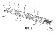
ここで図面を参照すると、同様の数字は同様の構成要素又は工程を指し、様々な例示的実施形態の広範な態様が開示されている。図1は、上面2及び下面3(図2に図示)を有する外科用鋸刃1の図である。鋸刃は、右側側縁部4a及び左側側縁部4bを有する第1の端部4を含み得、第1の端部は、動力鋸の振動ヘッドと接続するように構成されている。鋸刃の第2の切断端部6は、内側歯5a及び外側歯5bを含む複数の歯5をその上に有し、歯5bは、第2の端部の右側側縁部及び左側側縁部にある。細長いシャンク7は、第1の端部と第2の端部とを接続する。シャンク7は、それぞれ右側側縁部及び左側側縁部7a及び7bを有し得る。様々な実施形態では、鋸刃1の第1の端部4は、細長いシャンク7よりも狭く、停止面8が、第1の端部と細長いシャンクとの接続部にある。停止面8は、振動ヘッドに対する鋸刃の正確な位置決めを確実にするために、動力鋸の振動ヘッドと係合するように構成され得る。
Referring now to the drawings, in which like numerals refer to like components or steps, a broad range of aspects of various exemplary embodiments are disclosed. FIG. 1 is a diagram of a
様々な実施形態では、細長いシャンク7は、上面及び下面を有し、シャンク7内の細長い穴10が、シャンクの上面から下面まで延在する。細長い穴10は、鋸刃1の共振周波数を制御するように構成され得る。細長い穴10のサイズはまた、鋸刃1の動的剛性を最適化するように選択され得る。共振周波数Wは、以下の式によって質量M及び剛性Kに依存する。
In various embodiments, the
![]()
![]()
したがって、質量を低減すること、及び/又は剛性を増加させることによって、共振周波数を増加させることができる。穴10の存在が、鋸刃1の全体の質量を低減するため、それは、鋸刃の共振周波数を増加させるのに役立つ。穴10の形状は、鋸刃の剛性に影響を与え得る。シャンク7内の支柱11が、鋸刃の第2の端部を刃に接続する。支柱11の厚さは、穴10の幅に依存する。穴10の面積を一定に保持しながら穴10の形状を変更し、これにより刃の質量定数を保持すると、共振周波数に影響を与える。穴10が広い場合、支柱11の幅は小さくてもよく、刃の剛性Kを低減し、刃の共振周波数を減少させる。穴10の面積を変化させることなく穴10の幅を低減すると、支柱11の幅が増加し、刃1の剛性Kが増加し、結果として共振周波数が増加する。
Therefore, the resonant frequency can be increased by reducing the mass and/or increasing the stiffness. Since the presence of the
また、穴10の面積を変化させることにより、刃の質量が変わり、共振周波数に影響を与え、穴10の面積の増加は、質量Mを低減させ、共振周波数を増加させる。共振周波数は、穴10の面積、及び支柱11の幅を均衡させることによって最適化され得る。
Also, changing the area of the
本明細書に開示される様々な実施形態は、上面及び下面を有する外科用鋸刃であって、
右側側縁部及び左側側縁部を有する第1の端部であって、設計された振動周波数で動作する動力鋸の振動ヘッドに接続するように構成されている、第1の端部と、
複数の歯を上に有する第2の端部と、
第1の端部と第2の端部とを接続する細長いシャンクと、を有する、外科用鋸刃に関する。様々な実施形態では、細長いシャンクは、上面及び下面を有し、シャンク内の少なくとも1つの穴は、上面から下面まで延在し、シャンク内の穴の形状及びサイズは、鋸刃の共振周波数を最適化するように構成されている。シャンク内の穴は、鋸刃の共振周波数が動力鋸の振動ヘッドの振動周波数よりも大きいことを確実にし、それによって鋸刃が使用中に共振しないことを確実にするように構成され得る。様々な実施形態では、穴は、単一の細長い穴であり得る。様々な実施形態では、シャンク内の穴は、楕円形の穴、円形の穴、又は多角形の穴であり得る。様々な実施形態では、シャンク内の穴は、単一の大きな円形の穴であり得る。本明細書に開示されるいくつかの実施形態は、単一の円形又は細長い穴の代わりに、シャンク内に一連の複数の小さい穴を含み得る。
Various embodiments disclosed herein include a surgical saw blade having an upper surface and a lower surface,
a first end having a right side edge and a left side edge, the first end configured to connect to an oscillating head of a power saw operating at a designed vibration frequency;
a second end having a plurality of teeth thereon;
and an elongated shank connecting the first end and the second end. In various embodiments, the elongated shank has an upper surface and a lower surface, at least one hole in the shank extends from the upper surface to the lower surface, and the shape and size of the hole in the shank is configured to optimize the resonant frequency of the saw blade. The hole in the shank can be configured to ensure that the resonant frequency of the saw blade is greater than the vibration frequency of the vibration head of the power saw, thereby ensuring that the saw blade does not resonate during use. In various embodiments, the hole can be a single elongated hole. In various embodiments, the hole in the shank can be an oval hole, a circular hole, or a polygonal hole. In various embodiments, the hole in the shank can be a single large circular hole. Some embodiments disclosed herein may include a series of multiple small holes in the shank instead of a single circular or elongated hole.
様々な実施形態では、外科用鋸刃は、上面及び下面を有する細長いシャンクを有し、シャンク内の複数の穴が、上面から下面まで延在する。複数の穴は、鋸刃の共振周波数が振動ヘッドの振動周波数よりも大きいことを確実にするように構成され得る。シャンク内の複数の穴は、複数の円形の穴、複数の多角形の穴、又は円形の穴と多角形の穴との組み合わせであり得る。 In various embodiments, the surgical saw blade has an elongated shank having an upper surface and a lower surface, with multiple holes in the shank extending from the upper surface to the lower surface. The multiple holes can be configured to ensure that the resonant frequency of the saw blade is greater than the vibration frequency of the vibrating head. The multiple holes in the shank can be multiple circular holes, multiple polygonal holes, or a combination of circular and polygonal holes.
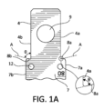
様々な実施形態では、外科用鋸刃1は、鋸刃の第1の端部4の右側側縁部4aを細長いシャンク7の右側側縁部7aに接続する第1の停止面8aと、第1の端部4の左側側縁部4bを細長いシャンク7の左側側縁部7bに接続する第2の停止面8bと、を含む、停止面8を有する。第1の停止面及び第2の停止面は、動力鋸の振動ヘッドと係合するように構成され得る。図1Aに示される様々な実施形態では、第2の停止面8b及び左側側縁部4bは、角度θで交わり、鋸刃の左側に角度付き表面を形成し得、θは、鋭角、直角、又は鈍角であり得る。同様に、第1の停止面8a及び右側側縁部4aは、対応する角度θで交わり、鋸刃の右側に角度付き表面を形成し得る。鋸刃の停止面8と第1の端部の側面とによって形成された右側及び左側の角度付き表面は、動力鋸の振動ヘッド上の対応する角度付き表面と係合するように構成されている。右側及び左側の停止面8a及び8bが振動ヘッドと係合するとき、停止面は、鋸刃の振動ヘッド内への更なる長手方向の移動を防止し、鋸刃の正確な位置決めを確実にする。様々な実施形態では、停止面8a及び8bは、所定の角度θで対応する縁部4a及び4bを満たし得、停止面8a及び8bは、平面状の表面又は湾曲面であり得る。角度θは、鋭角、鈍角、又は直角であり得る。停止面8a及び8bが平面状の表面である場合、それらは、動力鋸の振動ヘッド上の対応する平面状の表面と係合するように構成されている。停止面8a及び8bが湾曲面である場合、それらは、動力鋸の振動ヘッド上の対応する湾曲面と係合するように構成されている。様々な実施形態では、停止面8a及び8bと、対応する縁部4a及び4bとの間の交点は、丸みを帯びていてもよく、停止面8a及び8bは、平面状の表面又は湾曲面であってもよい。停止面と対応する縁部4a及び4bとの間の交点が丸みを帯びていてもよい実施形態では、交点に隣接する点で停止面8a及び8bに接している線Aは、図1Aに示されるように、所定の角度θで縁部4a及び4bを満たし得る。
In various embodiments, the
図1A及び図2に示すように、鋸刃1の第1の端部4は、上面及び下面を有し得、第1の端部内の穴9は、上面から下面まで延在する。鋸刃の第1の端部の上面及び下面は、動力鋸上の第1のクランプ面及び第2のクランプ面と係合するように構成され得、これは、本開示において後で更に説明される。第1の端部内の穴は、第1のクランプ面及び第2のクランプ面のうちの少なくとも1つの上の上昇した隆起部と係合するように構成され得る。
As shown in FIGS. 1A and 2, the
本明細書に開示される様々な実施形態は、上面及び下面を有する外科用鋸刃に関する。鋸刃は、右側側縁部及び左側側縁部を有する第1の端部であって、第1の端部が、動力鋸の振動ヘッドに接続するように構成されている、第1の端部と、複数の歯を上に有する第2の端部と、右側側縁部及び左側側縁部を有する細長いシャンクであって、細長いシャンクが、第1の端部と第2の端部とを接続する、細長いシャンクと、を含み得る。様々な実施形態では、振動ヘッドと係合するように構成されている少なくとも1つの停止面は、第1の端部を細長いシャンクに接続する。様々な実施形態では、停止面は、鋸刃の第1の端部の対向する縁部上の第1の停止面及び第2の停止面を含み得、第1の停止面及び第2の停止面は、一緒に鋸刃の第1の端部を細長いシャンクに接続する。 Various embodiments disclosed herein relate to a surgical saw blade having an upper surface and a lower surface. The saw blade may include a first end having right and left side edges, the first end configured to connect to an oscillating head of a power saw, a second end having a plurality of teeth thereon, and an elongated shank having right and left side edges, the elongated shank connecting the first and second ends. In various embodiments, at least one stop surface configured to engage the oscillating head connects the first end to the elongated shank. In various embodiments, the stop surface may include a first stop surface and a second stop surface on opposing edges of the first end of the saw blade, the first stop surface and the second stop surface together connecting the first end of the saw blade to the elongated shank.
外科用鋸刃は、細長いシャンク上に少なくとも3つの位置合わせ穴を含み得る。細長いシャンク上の少なくとも3つの位置合わせ穴は、様々な方法で鋸刃上に自由に分配され得る。図1Aに示される様々な実施形態では、少なくとも1つの位置合わせ穴12は、少なくとも1つの停止面8a又は8bに近接していてもよい。図1Bに示されるように、少なくとも1つの位置合わせ穴13は、切断縁部に近接して、鋸刃の第2の端部6の近くに位置決めされ得る。少なくとも1つの位置合わせ穴は、鋸刃の第1の端部の近く、停止面の近くに位置決めされ得、少なくとも1つの位置合わせ穴は、鋸刃の第2の切断端部の近くに位置決めされ得る。第3の位置合わせ穴は、鋸刃の第1の端部の近く、鋸刃の第2の端部の近く、又はシャンク上、鋸刃の第1の端部と第2の端部との間に位置決めされ得る。少なくとも2つの位置合わせ穴は、鋸刃の片側に位置決めされ得、第3の穴は、鋸刃の反対側に位置決めされている。図1Aに示される様々な実施形態では、位置合わせ穴12は、停止面8a及び8bの各々に近接していてもよい。
The surgical saw blade may include at least three alignment holes on the elongated shank. The at least three alignment holes on the elongated shank may be distributed freely on the saw blade in various ways. In various embodiments shown in FIG. 1A, at least one
様々な実施形態では、外科用鋸刃は、細長いシャンク上に少なくとも3つの位置合わせ穴を含み、位置合わせ穴は、鋸刃の長さに沿って又は幅にわたって分配されている。様々な実施形態では、外科用鋸刃は、細長いシャンク上に少なくとも2つの第1の位置合わせ穴を含み、各位置合わせ穴は、外科用鋸刃の第2の端部に近接している。様々な実施形態では、外科用鋸刃は、細長いシャンク上の少なくとも2つの第1の位置合わせ穴(第1の停止面及び第2の停止面に近接している)、及び細長いシャンク上の少なくとも1つの第2の位置合わせ穴(外科用鋸刃の第2の端部に近接している)を含む。 In various embodiments, the surgical saw blade includes at least three alignment holes on the elongated shank, the alignment holes being distributed along the length or across the width of the saw blade. In various embodiments, the surgical saw blade includes at least two first alignment holes on the elongated shank, each alignment hole being proximate to the second end of the surgical saw blade. In various embodiments, the surgical saw blade includes at least two first alignment holes on the elongated shank (proximate to the first stop surface and the second stop surface) and at least one second alignment hole on the elongated shank (proximate to the second end of the surgical saw blade).
図1Bは、外科用鋸刃の切断端部6を示す。切断端部6は、その上に取り付けられた複数の第1の歯5aを有する。各第1の歯5aは、タイン14の遠位端部上に取り付けられている。各対の隣接するタインは、長手方向スロット15によって分離され得、各長手方向スロット15の遠位端部は、対応する対の隣接するタインを接続するウェブ16によって架橋されている。鋸刃が、動力鋸によって横方向に振動されると、ウェブ16の表面は、鋸刃1の上面及び/又は下面から凹んでおり、それによって、鋸の動作中に発生した大鋸屑及び削屑が、ウェブ16の周りを長手方向スロット16内に移動することを可能にする。長手方向スロット16は、歯における切断縁部の先端において発生する切断材料が、歯5aから離れるように移動することを可能にし、鋸の動作中に切断縁部における切断材料の蓄積を防止する。図1Bに示される様々な実施形態では、少なくとも1つの位置合わせ穴13は、外科用鋸刃1の切断端部6、例えば、歯5又は長手方向スロット若しくは溝15の近くに近接していてもよい。図1Aに示される様々な実施形態では、少なくとも2つの位置合わせ穴13は、外科用鋸刃1の切断端部6に近接していてもよい。
FIG. 1B shows the cutting
様々な実施形態では、外科用鋸刃の切断端部6は、平面状の上面及び下面を有し得、複数の第1の歯がその上に取り付けられている。鋸刃の第2の端部は、一定の厚さを有してもよく、溝15又はその中の他の特徴部はない。代替的に、鋸刃の第2の端部は、可変厚さを有し得、スロット15は、切断端部6の全厚を通って延在する。代替的に、鋸刃の第2の端部は、複数の溝によって分離された歯を有し得、各溝は、切断端部6の全厚を通って部分的に延在する。鋸刃の第2の端部内のスロット15及び/又は溝は、鋸刃上の歯から離れるように鋸の動作中に発生する粉塵を運ぶように構成されている。様々な実施形態では、鋸刃の第2の切断端部上の任意の対の隣接する歯は、長手方向溝(複数可)によって分離され得る。
In various embodiments, the cutting
ウェブ16は、鋸刃の全体的な厚さよりも薄くてもよく、切断材料が、ウェブ16上及び/又はウェブ16下を容易に長手方向スロット15内に移動することを可能にする。切断端部6の左側縁部及び右側縁部は、タイン14aを有し得る。タイン14aは、単一の歯を有し得、それらが1つの内側のみに隣接するタインを有することを除いて、タイン14と構造的に同様であり得る。代替的に、タイン14aは、他のタイン14に対して厚さが増加してもよく、各々が遠位端部において2つの歯を有し得る。様々な実施形態では、各タイン14a上に外側歯5b及び内側歯5aが存在し得、各歯5aは、長手方向スロット15への入口においてタイン14aの端部に位置決めされ得る。タイン14aの端部における歯5aは、ウェブ16によって、隣接するタイン14上の歯5aと接続され得る。各タイン14a上の外側歯は、歯5bであり、歯5bは、タイン14a上の歯5aに隣接している。様々な実施形態では、タイン14aの端部における歯5a、及び歯5bは、溝14などの長手方向スロット又は溝によって分離されてもよく、又は分離されなくてもよい。様々な実施形態では、外側タイン14a及び内側タイン14は各々、単一の歯と同様の幅を有する。様々な実施形態では、外側タイン14aは、2つの歯を有し、内側タイン14よりも2~6倍、又は約4倍広い場合がある。タイン14aの厚さの増加は、鋸刃1の切断端部6の剛性を増加させ得る。図1Bに見られるように、歯5は非対称であり得、各歯5a及び5bは、外側切断縁部5c及び内側切断縁部5dを有し得、縁部5c及び5dは、鋭角で交わり、外側切断面5cは、内側切断縁部5dよりも鋸刃1の縁部に近い。様々な実施形態では、各歯5a及び5bの外縁部5cは、鋸刃1の縁部と平行又はほぼ平行であり得、角度βを形成し得、βは、鋸刃の縁部と160°~180°である。様々な実施形態では、各歯5a及び5bの内縁部5dは、対応する外縁部5cと30°~45°の角度αを形成し得る。様々な実施形態では、歯5は各々、鋸刃1の縁部に平行な線について非対称であり得る。様々な実施形態では、鋸刃1は、対称歯及び非対称歯の組み合わせを含み得る。
The
図2及び図3は、図1の外科用鋸刃の上面図及び底面図をそれぞれ示す。動力鋸に取設されるように構成されている、停止面8a及び8bのシャンク7及び第1の端部4に対する関係が、図2及び図3に見られる。細長いシャンク7は、一般に、停止面8a及び8bから位置合わせ穴13まで延在する。鋸刃の切断端部は、位置合わせ穴13から歯5a及び5bの先端まで延在すると考えられ得る。
2 and 3 show top and bottom views, respectively, of the surgical saw blade of FIG. 1. The relationship of the stop surfaces 8a and 8b to the
図4は、外科用鋸刃1の切断端部6の立面図を示す。切断端部6の外縁部には、2つの非対称歯5bがある。各非対称歯5bは、鋸刃1の縁部と平行又はほぼ平行である外側切断縁部5cと、内側切断縁部5dと、を含み得る。内側切断縁部5dは、鋸刃1の縁部に平行な線と鋭角を形成し得る。内側歯5aはまた、鋸刃1の縁部とほぼ平行である外側切断縁部5cと、鋸刃1の縁部と鋭角を形成する内側切断縁部5dと、を有し得る。鋸刃1は、長手方向軸に沿って対称面を有し得るため、切断端部6の左側の歯5は、右側の対応する歯の鏡像であり得る。そのような対称面が存在する場合、各歯5a及び各歯5bは、切断端部6の上面において同じ幅、及び切断端部6の下面において同じ幅を有し、切断縁部の上面及び下面における幅は、同じであっても異なっていてもよい。代替的に、切断端部6は、鋸刃1の長手方向軸を中心に180°回転したときに、2倍の回転対称性を有し得る。
4 shows an elevational view of the cutting
切断端部が2倍回転対称性を有する場合、全ての歯は、切断縁部6の上面から切断縁部6の下面まで一定の幅を有し得る。代替的に、2倍回転対称性が存在する場合、鋸刃6の右側の各歯5の幅は、切断端部6の上面における第1の選択された幅から切断端部6の下面において第2の選択された幅まで変化し得る。回転対称性を維持するために、鋸刃6の左側の各歯5の幅は、切断端部6の上面の第2の選択された幅から切断端部6の下面の第1の選択された幅まで変化し得る。図4は、回転対称性を有する切断端部6を示し、切断端部6上の歯5aは、
切断端部6の右側の下面よりも上面において狭く、かつ
切断端部6の左側の上面よりも下面において狭い。
If the cutting edge has two-fold rotational symmetry, all of the teeth may have a constant width from the top surface of the
The upper surface of the
対称面又は回転対称面が鋸刃1の周りに存在する場合、切断端部6の反対側の対応する歯の内側切断縁部5dは互いに向かい合う。任意の2つの隣接する歯5aの間に、図4において視認可能である開口部を有する長手方向スロット15が存在する。長手方向スロット15への開口部は、図4において視認可能であり、各スロット15への開口部は、ウェブ16によって部分的に閉塞されている。各ウェブ16は、隣接する歯15aを運ぶ2つのタインを連結し、タインを固定距離だけ離れて保持することによって、隣接する歯15aの間の相対的な移動を防止する。
When a plane of symmetry or rotational symmetry exists around the
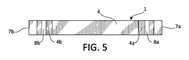
図5は、外科用鋸刃1の第1の端部4の立面図を示し、端部4は、動力鋸に取設されるように構成されている。図5に見られるように、停止面8aは、鋸刃の第1の端部4の右側側縁部4aを細長いシャンク7の右側側縁部7aに接続し、停止面8bは、第1の端部4の左側側縁部4bを細長いシャンク7の左側側縁部7bに接続する。
Figure 5 shows an elevational view of the
図5及び図6は、外科用鋸刃1の右側立面図及び左側立面図を示す。
Figures 5 and 6 show right and left elevational views of the
図8は、図2の矢印8の斜視図から見た、図1の鋸刃1の三次元断面図を示す。外科用鋸刃1は、動力鋸の振動ヘッドに接続するように構成されている第1の端部4と、図8に示される内側歯5aを含む複数の歯を有する第2の切断端部6と、第1の端部4及び切断端部6を接続する細長いシャンク7と、を有する。図8に見られるように、鋸刃1の第1の端部4は、鋸刃の上面から下面まで延在する、第1の端部内の穴9を有し得る。様々な実施形態では、細長いシャンク7は、シャンクの上面から下面まで延在する、シャンク7内の少なくとも1つの穴10を有する。穴10は、鋸刃1の共振周波数を制御するように構成され得る。様々な実施形態では、穴10の形状及びサイズは、鋸刃1の共振周波数が鋸の動作中に鋸刃の振動周波数よりも高いことを確実にするように構成されている。様々な実施形態では、鋸刃1は、振動外科用鋸ヘッドに取設されるように構成され、穴10は、鋸刃1の共振周波数が鋸ヘッドの振動周波数よりも高いことを確実にするように構成されている。図9の断面図を見るとき、穴10は、前景で見ることができ、細長い穴10の後縁部は、支柱11の内縁部を画定する。シャンク7内の支柱11は、細長い穴10の背面で視認可能である。各歯5aは、少なくとも1つの長手方向スロット15の開口部に隣接し、隣接する長手方向スロット15は、ウェブ16によって接続されている。
8 shows a three-dimensional cross-sectional view of the
様々な実施形態では、シャンク内の穴10は、単一の細長い穴、単一の楕円形の穴、又は単一の大きい円形の穴であり得る。本明細書に開示されるいくつかの実施形態は、単一の円形、楕円形、又は細長い穴の代わりに、シャンク内に一連の複数の小さい穴10を含み得る。シャンク内に一連の複数の小さい穴10を含むいくつかの実施形態では、小さい穴10は各々、同じ幾何学形状を有し得、例えば、一連の小さい穴は、一連の円形の穴、一連の楕円形の穴、又は一連の多角形の穴であり得る。シャンク内に一連の複数の小さい穴を含むいくつかの実施形態では、小さい穴10は、異なる幾何学形状、例えば、多角形の穴と組み合わせた一連の円形の穴、又は長方形若しくは平行四辺形の穴と組み合わせた一連の正方形の穴を有し得る。
In various embodiments, the
図9は、動力鋸の手持ち式外科用鋸ハンドル20内に取り付けられている鋸刃1の第1の端部4を示す。動力鋸ハンドル20は、2つのクランプ面21を含み、上部クランプ面22及び下部クランプ面23をそれぞれ含み得る。上部クランプ面22は、動力鋸ハンドル20の振動ヘッド28の下面であり得る。下部クランプ面23は、クランプスリーブ27上に取り付けられ得、クランプスリーブ27は、振動ヘッド28とは独立して上昇又は下降され得る。図9の構成では、クランプスリーブ27は、クランプ面22と23との間のギャップを増加させ、かつ鋸刃1の第1の端部4をそれらの間に挿入することを可能にするように、クランプ面22に対して下降され得る。次いで、鋸刃1の第1の端部4は、クランプスリーブ27をクランプ面22に対して上昇させることによって、クランプ面22と23との間にクランプされ得る。
9 shows the
様々な実施形態では、第1の穴26は、振動ヘッド28及び上部クランプ面22を通って延在する。対応する穴25は、下部クランプ面23内に延在し、そのため、穴25及び26は、互いに位置合わせしている。鋸刃1が、クランプ面21の間に、振動鋸内に適切に挿入されると、鋸刃内の穴9は、動力鋸ハンドル20内の穴25及び26の各々と位置合わせされる。ペグ26aが、振動ヘッド28内の穴26内に取り付けられ得、矢印Aの方向に、鋸刃内の穴9を通って、クランプスリーブ27内の穴25内に入れられ得る。したがって、ペグ26aは、鋸刃1を鋸ハンドル20から係脱することを防止するように、鋸刃1を動力鋸ハンドル20内に固定する。
In various embodiments, a
様々な実施形態では、振動ヘッド28を通って延在する第1の穴26、及び下部クランプ面23内に延在する対応する穴25は各々、ペグ27の半径とほぼ等しい、共通の半径r1を有し得る。様々な実施形態では、鋸刃1内の穴9は、半径r1よりも大きい半径r2を有し得る。様々な実施形態では、上部及び下部クランプ面22及び23のうちの少なくとも1つは、その上に隆起部24を有し、隆起部24は、r2の外径及びwの幅を有し、w=r2-r1である。したがって、隆起部は、鋸刃1上の穴9と係合するように構成されている外縁部を有する。隆起部は、ペグ26aと係合するように構成されている外縁部を有する。隆起部24は、振動ヘッド28が鋸刃1を振動させるときに、クランプ面21に対する鋸刃1の移動を防止する。
In various embodiments, the
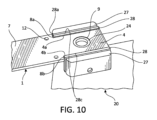
図10は、下部クランプ面23の平面に沿った図9の矢印10の方向に見られる、動力鋸ハンドル20内に取り付けられた鋸刃1の図である。第1の端部4は、第1の端部の縁部4a及び4bが振動ヘッド28の対向する接触面28cに接触するように位置決めされる。振動ヘッド28は、平面接触面28cの移動を通して、鋸刃を右から左に横方向に振動させるように構成されている。振動ヘッドは、刃への枢動接続を有しないため、振動ヘッド28の近くのシャンク7における鋸刃の横方向の移動は、鋸刃1の切断端部6(図10に図示せず)の横方向の移動と振幅において同様である。
Figure 10 is a view of the
振動ヘッド28上の第1の停止面28aは、鋸刃1上の停止面8aに接触する。振動ヘッド28上の第2の停止面28bは、鋸刃1上の停止面8bに接触する。様々な実施形態では、湾曲又は平面であり得る振動ヘッド28の停止面28a及び28bはそれぞれ各々、対応する停止面8a又は8bと嵌合する(mate)ように構成されている。鋸刃1上の停止面8a及び8bは各々、振動ヘッド28上の停止面28a又は28bとの直接的な表面と表面との接触を行い得る。上述のように、隆起部24は、鋸刃1上の穴9内に嵌合する(fit)。
The
図11は、外科用鋸29と組み合わせた鋸刃1を示し、外科用鋸20は、バレル30、ハンドル31、トリガ32、及び振動ヘッド28を含む。鋸刃1は、クランプスリーブ27を介して外科用鋸29に接続されている。カバー39は、鋸刃1の切断端部の上に取り付けられている。複数のマーカ34を有する鋸アレイ33は、外科用鋸29に取り付けられている。位置決めマーカ35は、図11にも示されており、位置決めマーカ35は、複数のマーカ37を有する位置決めアレイ36、及び無菌ポインタ先端を有するポインタ38を含む。ポインタ38上の滅菌ポインタ先端は、鋸刃1上の位置合わせ穴12及び13のうちの1つ内に嵌合する。次いで、マーカ34及び37は、カメラで画像化され、鋸アレイ33に対する位置決めアレイ36の正確な位置を決定するために使用される。ポインタ38の長さが既知であるため、鋸アレイ33に対する鋸刃1の位置の決定を可能にし、使用者が外科用鋸29に対する鋸刃1の位置を決定することを可能にする。様々な実施形態では、ポインタ38上の無菌ポインタ先端は、鋸刃1上の位置合わせ穴12及び13のうちの2つ又は3つ内に個別に位置決めされ得る。各位置合わせ穴12及び13について、マーカ34及び37を使用して、各位置合わせ穴における鋸アレイ33に対する位置決めアレイ36の正確な位置を決定し得、使用者が、鋸刃1の切断面を決定し得るように、複数の点において鋸アレイ33に対する鋸刃1の位置の決定を可能にする。
11 shows a
様々な実施形態が、それらの特定の態様を参照しながら説明されてきたが、開示された主題は、他の実施形態も可能であり、またその詳細については、種々の点において修正が可能であることを理解されたい。当業者にはすでに明らかなように、本開示の趣旨及び範囲内に留めながら変形及び修正に影響を与えることが可能である。したがって、前述の開示、説明、及び図面は、単に例示的な目的のみのためであって、本発明を何ら限定するものではなく、本発明は、特許請求の範囲によってのみ定義される。 Although various embodiments have been described with reference to specific aspects thereof, it should be understood that the disclosed subject matter is capable of other embodiments and modifications in its details in various respects. As will be readily apparent to those skilled in the art, variations and modifications can be effected while remaining within the spirit and scope of the disclosure. Accordingly, the foregoing disclosure, description, and drawings are for illustrative purposes only and are not intended to limit the invention, which is defined solely by the claims.
〔実施の態様〕
(1) 上面及び下面を有する外科用鋸刃であって、
右側側縁部及び左側側縁部を有する第1の端部であって、前記第1の端部が、動力鋸の振動ヘッドに接続するように構成されている、第1の端部と、
複数の歯を上に有する第2の端部と、
右側側縁部及び左側側縁部を有する細長いシャンクであって、前記細長いシャンクが、前記第1の端部と前記第2の端部とを接続する、細長いシャンクと、を備え、
前記第1の端部が、前記シャンクよりも狭く、停止面が、前記第1の端部を前記細長いシャンクに接続し、
前記停止面が、前記振動ヘッドに対する前記鋸刃の正確な位置決めを確実にするように、前記振動ヘッドと係合するように構成されている、外科用鋸刃。
(2) 前記停止面が、
前記第1の端部の前記右側側縁部を前記細長いシャンクの前記右側側縁部に接続する第1の停止面と、
前記第1の端部の前記左側側縁部を前記細長いシャンクの前記左側側縁部に接続する第2の停止面と、を備え、
前記第1の停止面及び前記第2の停止面が、前記振動ヘッドと係合するように構成されている、実施態様1に記載の外科用鋸刃。
(3) 前記第1の端部が、上面及び下面を有し、前記第1の端部内の穴が、前記上面から前記下面まで延在し、
前記上面及び前記下面が、前記動力鋸上の第1及び第2のクランプ面と係合するように構成され、
前記第1の端部内の前記穴が、前記第1及び第2のクランプ面のうちの少なくとも1つの上の上昇した隆起部と係合するように構成されている、実施態様1に記載の外科用鋸刃。
(4) 前記細長いシャンクが、上面及び下面を有し、前記シャンク内の穴が、前記上面から前記下面まで延在している、実施態様1に記載の外科用鋸刃。
(5) 前記シャンク内の前記穴が、前記鋸刃の共振周波数が前記振動ヘッドの振動周波数よりも大きいことを確実にするように構成されている、実施態様4に記載の外科用鋸刃。
[Embodiment]
(1) A surgical saw blade having an upper surface and a lower surface,
a first end having a right side edge and a left side edge, the first end configured to connect to an oscillating head of a power saw;
a second end having a plurality of teeth thereon;
an elongate shank having a right side edge and a left side edge, the elongate shank connecting the first end and the second end;
the first end is narrower than the shank, and a stop surface connects the first end to the elongated shank;
A surgical saw blade, wherein the stop surface is configured to engage the oscillating head to ensure precise positioning of the saw blade relative to the oscillating head.
(2) The stop surface is
a first stop surface connecting the right side edge of the first end to the right side edge of the elongate shank;
a second stop surface connecting the left side edge of the first end to the left side edge of the elongate shank;
2. The surgical saw blade of
(3) the first end has an upper surface and a lower surface, and a hole in the first end extends from the upper surface to the lower surface;
the upper and lower surfaces are configured to engage first and second clamping surfaces on the power saw;
2. The surgical saw blade of
4. The surgical saw blade of
5. The surgical saw blade of
(6) 前記シャンク内の前記穴が、細長い穴、楕円形の穴、円形の穴、又は多角形の穴である、実施態様4に記載の外科用鋸刃。
(7) 前記シャンク内の前記穴が、単一の細長い穴である、実施態様4に記載の外科用鋸刃。
(8) 前記細長いシャンクが、上面及び下面を有し、前記シャンク内の複数の穴が、前記上面から前記下面まで延在し、前記複数の穴が、前記鋸刃の共振周波数が前記振動ヘッドの振動周波数よりも大きいことを確実にするように構成されている、実施態様1に記載の外科用鋸刃。
(9) 前記シャンク内の前記複数の穴が、複数の円形の穴、複数の多角形の穴、又は円形の穴と多角形の穴との組み合わせである、実施態様1に記載の外科用鋸刃。
(10) 前記細長いシャンク上に少なくとも3つの位置合わせ穴を更に備え、前記位置合わせ穴が、前記鋸刃の長さに沿って又は幅にわたって分配されている、実施態様1に記載の外科用鋸刃。
6. The surgical saw blade of
7. The surgical saw blade of
8. The surgical saw blade of
9. The surgical saw blade of
10. The surgical saw blade of
(11) 前記細長いシャンク上に少なくとも2つの位置合わせ穴を更に備え、各位置合わせ穴が、前記外科用鋸刃の前記第2の端部に近接している、実施態様1に記載の外科用鋸刃。
(12) 前記第1の停止面及び前記第2の停止面に近接して、前記細長いシャンク上に少なくとも2つの第1の位置合わせ穴を更に備える、実施態様2に記載の外科用鋸刃。
(13) 前記外科用鋸刃の前記第2の端部に近接して、前記細長いシャンク上に少なくとも1つの第2の位置合わせ穴を更に備える、実施態様8に記載の外科用鋸刃。
(14) 前記第2の端部が、複数の第1の歯をその上に有し、
各第1の歯が、タインの遠位端部上に取り付けられ、
各対の隣接するタインが、長手方向スロットによって分離されており、
各長手方向スロットの遠位端部が、対応する対の隣接するタインを接続するウェブによって架橋されている、実施態様1に記載の外科用鋸刃。
(15) 前記細長いシャンクが、上面及び下面を有し、前記シャンク内の細長い穴が、前記上面から前記下面まで延在している、実施態様11に記載の外科用鋸刃。
11. The surgical saw blade of
12. The surgical saw blade of
13. The surgical saw blade of
(14) The second end has a plurality of first teeth thereon;
Each first tooth is mounted on a distal end of a tine;
adjacent tines of each pair are separated by a longitudinal slot;
2. The surgical saw blade of
15. The surgical saw blade of
(16) 前記細長い穴のサイズが、前記鋸刃の共振周波数が前記振動ヘッドの振動周波数よりも大きいことを確実にするように選択されている、実施態様11に記載の外科用鋸刃。
(17) 前記第2の端部が、複数の第1の歯をその上に有し、
各第1の歯が、タインの遠位端部上に取り付けられ、
各対の隣接するタインが、長手方向スロットによって分離されており、
各長手方向スロットの遠位端部が、対応する対の隣接するタインを接続するウェブによって架橋されている、実施態様11に記載の外科用鋸刃。
(18) 前記細長いシャンク上に少なくとも3つの位置合わせ穴を更に備え、第1の位置合わせ穴が、長手方向スロットに近接し、第2の位置合わせ穴が、前記停止面に近接している、実施態様11に記載の外科用鋸刃。
(19) 外科用鋸アセンブリであって、組み合わせで、
実施態様1に記載の外科用鋸刃と、
手持ち式外科用鋸ハンドルと、を備え、前記手持ち式外科用鋸ハンドルが、
前記外科用鋸刃を横方向に振動させるように構成されている振動ヘッドを備え、前記振動ヘッドが、
前記外科用鋸の前記第1の端部の前記右側側縁部と係合するように構成されている第1の表面と、
前記外科用鋸の前記第1の端部の前記左側側縁部と係合するように構成されている第2の表面と、
前記停止面と係合するように構成されている第3の表面と、
前記鋸刃の前記第1の端部と係合するように構成されている少なくとも2つのクランプ面と、を備え、
前記クランプ面のうちの少なくとも1つが、隆起部を含み、前記隆起部が、前記鋸刃の前記第1の端部を通って延在する穴と係合するように構成されている、外科用鋸アセンブリ。
(20) 外科用鋸アセンブリであって、組み合わせで、
実施態様11に記載の外科用鋸刃と、
手持ち式外科用鋸ハンドルと、を備え、前記手持ち式外科用鋸ハンドルが、
前記外科用鋸刃を横方向に振動させるように構成されている振動ヘッドであって、前記振動ヘッドが、前記外科用鋸刃の前記第1の端部及び前記外科用鋸刃の前記停止面と係合するように構成されている、振動ヘッドと、
前記鋸刃の前記第1の端部の前記上面と係合するように構成されている第1のクランプ面と、
前記鋸刃の前記第1の端部の前記下面と係合するように構成されている第2のクランプ面と、
前記第1のクランプ面及び前記第2のクランプ面のうちの少なくとも1つの上の上昇した隆起部であって、前記上昇した隆起部が、前記鋸刃の前記第1の端部内の前記穴と係合するように構成されている、上昇した隆起部と、を備える、外科用鋸アセンブリ。
16. The surgical saw blade of
(17) The second end has a plurality of first teeth thereon;
Each first tooth is mounted on a distal end of a tine;
adjacent tines of each pair are separated by a longitudinal slot;
12. The surgical saw blade of
18. The surgical saw blade of
(19) A surgical saw assembly comprising, in combination:
A surgical saw blade according to
a hand-held surgical saw handle, said hand-held surgical saw handle comprising:
a vibration head configured to laterally vibrate the surgical saw blade, the vibration head comprising:
a first surface configured to engage the right side edge of the first end of the surgical saw;
a second surface configured to engage the left side edge of the first end of the surgical saw; and
a third surface configured to engage the stop surface; and
at least two clamping surfaces configured to engage the first end of the saw blade;
A surgical saw assembly, wherein at least one of the clamping surfaces includes a ridge configured to engage a bore extending through the first end of the saw blade.
(20) A surgical saw assembly comprising, in combination:
A surgical saw blade according to
a hand-held surgical saw handle, said hand-held surgical saw handle comprising:
an oscillating head configured to laterally oscillate the surgical saw blade, the oscillating head configured to engage the first end of the surgical saw blade and the stop surface of the surgical saw blade;
a first clamping surface configured to engage the top surface of the first end of the saw blade;
a second clamping surface configured to engage the underside of the first end of the saw blade; and
a raised ridge on at least one of the first clamping surface and the second clamping surface, the raised ridge configured to engage the hole in the first end of the saw blade.
(21) 上面及び下面を有する外科用鋸刃であって、前記鋸刃が、
上面、下面、及び前記上面から前記下面まで延在する穴を有する第1の端部であって、前記第1の端部が、動力鋸の振動ヘッドに接続するように構成されている、第1の端部と、
複数の歯を上に有する第2の端部と、
前記第2の端部に接続された細長いシャンクと、
前記第1の端部と前記細長いシャンクとを接続する停止面であって、前記停止面が、前記振動ヘッドの表面と係合するように成形されている、停止面と、を備え、
前記上面及び前記下面が、前記動力鋸上の第1及び第2のクランプ面と係合するように構成され、
前記第1の端部内の前記穴が、前記第1及び第2のクランプ面のうちの少なくとも1つの上の上昇した隆起部と係合するように構成されている、外科用鋸刃。
(21) A surgical saw blade having an upper surface and a lower surface, said saw blade comprising:
a first end having an upper surface, a lower surface, and a hole extending from the upper surface to the lower surface, the first end configured to connect to an oscillating head of a power saw;
a second end having a plurality of teeth thereon;
an elongated shank connected to the second end;
a stop surface connecting the first end and the elongated shank, the stop surface being shaped to engage a surface of the vibration head;
the upper and lower surfaces are configured to engage first and second clamping surfaces on the power saw;
A surgical saw blade, wherein the hole in the first end is configured to engage a raised ridge on at least one of the first and second clamping surfaces.
Claims (20)
右側側縁部及び左側側縁部を有する第1の端部であって、前記第1の端部が、動力鋸の振動ヘッドに接続するように構成されており、前記第1の端部の前記右側側縁部及び左側側縁部は、使用時に前記振動ヘッドに係合するように構成されている、第1の端部と、
第2の端部であって、複数の歯を前記第2の端部の表面上に有する第2の端部と、
右側側縁部及び左側側縁部を有する細長いシャンクであって、前記細長いシャンクが、前記第1の端部と前記第2の端部とを接続する、細長いシャンクと、を備え、
前記第1の端部が、前記細長いシャンクよりも狭く、前記第1の端部の表面が、前記第1の端部を前記細長いシャンクに接続し、
前記第1の端部の表面が停止面からなり、前記停止面が、前記振動ヘッドに対する前記外科用鋸刃の正確な位置決めを確実にするように、前記振動ヘッドと係合するように構成されており、
前記停止面は前記第1の端部の前記右側側縁部及び左側側縁部の少なくとも一方と鋭角をなすように構成されている、外科用鋸刃。 1. A surgical saw blade having an upper surface and a lower surface,
a first end having a right side edge and a left side edge, the first end configured to connect to an oscillating head of a power saw , the right side edge and the left side edge of the first end configured to engage the oscillating head in use ;
a second end having a plurality of teeth on a surface of the second end ;
an elongate shank having a right side edge and a left side edge, the elongate shank connecting the first end and the second end;
the first end is narrower than the elongate shank, and a surface of the first end connects the first end to the elongate shank;
a surface of the first end comprising a stop surface configured to engage the vibration head to ensure precise positioning of the surgical saw blade relative to the vibration head ;
The stop surface is configured to form an acute angle with at least one of the right and left side edges of the first end .
前記第1の端部の前記右側側縁部を前記細長いシャンクの前記右側側縁部に接続する第1の停止面と、
前記第1の端部の前記左側側縁部を前記細長いシャンクの前記左側側縁部に接続する第2の停止面と、を備え、
前記第1の停止面及び前記第2の停止面が、前記振動ヘッドと係合するように構成されている、請求項1に記載の外科用鋸刃。 The stop surface is
a first stop surface connecting the right side edge of the first end to the right side edge of the elongate shank;
a second stop surface connecting the left side edge of the first end to the left side edge of the elongate shank;
The surgical saw blade of claim 1 , wherein the first stop surface and the second stop surface are configured to engage the oscillating head.
前記第1の端部の前記上面及び下面が、前記動力鋸上の第1及び第2のクランプ面と係合するように構成され、
前記第1の端部内の前記穴が、前記第1及び第2のクランプ面のうちの少なくとも1つの上の上昇した隆起部と係合するように構成されている、請求項1に記載の外科用鋸刃。 the first end has an upper surface and a lower surface, a hole in the first end extending from the upper surface to the lower surface of the first end ;
the upper and lower surfaces of the first end are configured to engage first and second clamping surfaces on the power saw;
The surgical saw blade of claim 1 , wherein the hole in the first end is configured to engage a raised ridge on at least one of the first and second clamping surfaces.
各第1の歯が、タインの遠位端部上に取り付けられ、
各対の隣接するタインが、長手方向スロットによって分離されており、
各長手方向スロットの遠位端部が、対応する対の隣接するタインを接続するウェブによって架橋されている、請求項1に記載の外科用鋸刃。 the second end having a plurality of first teeth on a surface of the second end ;
Each first tooth is mounted on a distal end of a tine;
adjacent tines of each pair are separated by a longitudinal slot;
The surgical saw blade of claim 1 , wherein a distal end of each longitudinal slot is bridged by a web connecting adjacent tines of a corresponding pair.
各第1の歯が、タインの遠位端部上に取り付けられ、
各対の隣接するタインが、長手方向スロットによって分離されており、
各長手方向スロットの遠位端部が、対応する対の隣接するタインを接続するウェブによって架橋されている、請求項11に記載の外科用鋸刃。 the second end having a plurality of first teeth on a surface of the second end ;
Each first tooth is mounted on a distal end of a tine;
adjacent tines of each pair are separated by a longitudinal slot;
The surgical saw blade of claim 11 , wherein a distal end of each longitudinal slot is bridged by a web connecting adjacent tines of a corresponding pair.
請求項1に記載の外科用鋸刃と、
手持ち式外科用鋸ハンドルと、を備え、前記手持ち式外科用鋸ハンドルが、
前記外科用鋸刃を横方向に振動させるように構成されている前記振動ヘッドを備え、前記振動ヘッドが、
前記外科用鋸刃の前記第1の端部の前記右側側縁部と係合するように構成されている第1の表面と、
前記外科用鋸刃の前記第1の端部の前記左側側縁部と係合するように構成されている第2の表面と、
前記停止面と係合するように構成されている第3の表面と、
前記外科用鋸刃の前記第1の端部と係合するように構成されている少なくとも2つのクランプ面と、を備え、
前記クランプ面のうちの少なくとも1つが、隆起部を含み、前記隆起部が、前記外科用鋸刃の前記第1の端部を通って延在する穴と係合するように構成されている、外科用鋸アセンブリ。 1. A surgical saw assembly comprising, in combination:
A surgical saw blade according to claim 1;
a hand-held surgical saw handle, said hand-held surgical saw handle comprising:
a vibration head configured to laterally vibrate the surgical saw blade, the vibration head comprising:
a first surface configured to engage the right side edge of the first end of the surgical saw blade ;
a second surface configured to engage the left side edge of the first end of the surgical saw blade ; and
a third surface configured to engage the stop surface; and
at least two clamping surfaces configured to engage the first end of the surgical saw blade;
A surgical saw assembly, wherein at least one of the clamping surfaces includes a ridge configured to engage a bore extending through the first end of the surgical saw blade.
請求項11に記載の外科用鋸刃と、
手持ち式外科用鋸ハンドルと、を備え、前記手持ち式外科用鋸ハンドルが、
前記外科用鋸刃を横方向に振動させるように構成されている前記振動ヘッドであって、前記振動ヘッドが、前記外科用鋸刃の前記第1の端部及び前記外科用鋸刃の前記停止面と係合するように構成されている、前記振動ヘッドと、
前記外科用鋸刃の前記第1の端部の前記上面と係合するように構成されている第1のクランプ面と、
前記外科用鋸刃の前記第1の端部の前記下面と係合するように構成されている第2のクランプ面と、
前記第1のクランプ面及び前記第2のクランプ面のうちの少なくとも1つの上の上昇した隆起部であって、前記上昇した隆起部が、前記外科用鋸刃の前記第1の端部内の前記穴と係合するように構成されている、上昇した隆起部と、を備える、外科用鋸アセンブリ。 1. A surgical saw assembly comprising, in combination:
A surgical saw blade according to claim 11;
a hand-held surgical saw handle, said hand-held surgical saw handle comprising:
the vibration head configured to laterally vibrate the surgical saw blade, the vibration head configured to engage the first end of the surgical saw blade and the stop surface of the surgical saw blade;
a first clamping surface configured to engage the top surface of the first end of the surgical saw blade;
a second clamping surface configured to engage the underside of the first end of the surgical saw blade; and
a raised ridge on at least one of the first clamping surface and the second clamping surface, the raised ridge configured to engage the hole in the first end of the surgical saw blade.
Applications Claiming Priority (3)
| Application Number | Priority Date | Filing Date | Title |
|---|---|---|---|
| US16/657,524 | 2019-10-18 | ||
| US16/657,524 US11490898B2 (en) | 2019-10-18 | 2019-10-18 | Surgical saw blade |
| PCT/IB2020/058943 WO2021074720A1 (en) | 2019-10-18 | 2020-09-24 | Surgical saw blade |
Publications (2)
| Publication Number | Publication Date |
|---|---|
| JP2022552700A JP2022552700A (en) | 2022-12-19 |
| JP7581342B2 true JP7581342B2 (en) | 2024-11-12 |
Family
ID=72801760
Family Applications (1)
| Application Number | Title | Priority Date | Filing Date |
|---|---|---|---|
| JP2022522912A Active JP7581342B2 (en) | 2019-10-18 | 2020-09-24 | Surgical Saw Blades |
Country Status (6)
| Country | Link |
|---|---|
| US (4) | US11490898B2 (en) |
| EP (1) | EP4044937B1 (en) |
| JP (1) | JP7581342B2 (en) |
| CN (1) | CN114554982B (en) |
| AU (1) | AU2020368057A1 (en) |
| WO (1) | WO2021074720A1 (en) |
Families Citing this family (14)
| Publication number | Priority date | Publication date | Assignee | Title |
|---|---|---|---|---|
| US12232744B2 (en) | 2019-07-15 | 2025-02-25 | Stryker Corporation | Robotic hand-held surgical instrument systems and methods |
| US11490898B2 (en) * | 2019-10-18 | 2022-11-08 | Depuy Synthes Products, Inc | Surgical saw blade |
| CA3202597A1 (en) | 2020-12-18 | 2022-06-23 | Seamus Gilhooley | Surgical sagittal blade cartridge |
| USD1032838S1 (en) * | 2021-12-09 | 2024-06-25 | Agnes Medical Co., Ltd. | Surgery needle for skin treatment device |
| WO2023122295A2 (en) * | 2021-12-22 | 2023-06-29 | Innovations 4 Surgery, LLC | Medical devices and related methods for transforming bone, other tissue, or material |
| USD1049377S1 (en) * | 2022-04-18 | 2024-10-29 | Nikolina Poranek | Device for cavitation peeling of skin of head and facial hair |
| USD1084334S1 (en) * | 2022-06-22 | 2025-07-15 | Stryker European Operations Limited | Surgical blade cartridge |
| USD1084335S1 (en) * | 2022-06-22 | 2025-07-15 | Stryker European Operations Limited | Surgical blade cartridge |
| USD1059978S1 (en) * | 2023-03-14 | 2025-02-04 | DePuy Synthes Products, Inc. | Saw blade |
| USD1047636S1 (en) * | 2023-03-14 | 2024-10-22 | DePuy Synthes Products, Inc. | Saw blade |
| US12349925B2 (en) * | 2023-03-14 | 2025-07-08 | DePuy Synthes Products, Inc. | Powered surgical tool with an oscillating saw blade |
| WO2025010213A2 (en) | 2023-07-01 | 2025-01-09 | Innovations 4 Surgery, LLC | Medical cutting and drill devices having static components, retractable sheaths, sensors, navigation components, working blade bodies, rails, struts, channels for fluid and gas flow, hand-piece, robotic arm attachment capabilities, computing devices, and associated feedbacks and outputs |
| CN119423976B (en) * | 2023-08-03 | 2025-11-21 | 北京思灵机器人科技有限责任公司 | Binocular vision plane calibration method and device and plane bone cutting robot |
| US12446894B1 (en) | 2025-04-22 | 2025-10-21 | Stryker European Operations Limited | Saw blade for use in performing a medical procedure |
Citations (5)
| Publication number | Priority date | Publication date | Assignee | Title |
|---|---|---|---|---|
| US20050245935A1 (en) | 2004-04-29 | 2005-11-03 | Casey Conor P | Surgical saw blade |
| US20060206100A1 (en) | 2005-03-09 | 2006-09-14 | Brasseler Usa Medical Llc | Surgical apparatus and power module for same, and a method of preparing a surgical apparatus |
| JP3136851U (en) | 2007-08-10 | 2007-11-08 | 国立大学法人浜松医科大学 | Bone cutting blade |
| JP2009501059A (en) | 2005-07-14 | 2009-01-15 | ストライカー・コーポレイション | Surgical sagittal saw |
| JP2009511150A (en) | 2005-10-15 | 2009-03-19 | ストライカー・アイルランド・リミテッド | Surgical sagittal saw blade with inclined teeth and reciprocating saw blade with broach teeth |
Family Cites Families (42)
| Publication number | Priority date | Publication date | Assignee | Title |
|---|---|---|---|---|
| ZA879455B (en) | 1986-12-18 | 1989-07-26 | Pfizer | Process for preparing bis(ethoxythiocarbonyl)sulfide |
| US5122142A (en) * | 1990-09-13 | 1992-06-16 | Hall Surgical Division Of Zimmer, Inc. | Irrigating saw blade |
| US5263972A (en) * | 1991-01-11 | 1993-11-23 | Stryker Corporation | Surgical handpiece chuck and blade |
| USD337160S (en) * | 1991-01-11 | 1993-07-06 | Stryker Corporation | Sagittal saw blade base |
| US7527628B2 (en) * | 1991-05-30 | 2009-05-05 | Synvasive Technology, Inc. | Surgical saw blade having at least one pair of opposed teeth shaped as right triangles |
| US5306285A (en) * | 1993-04-30 | 1994-04-26 | Komet Medical | Surgical saw blade |
| USD459805S1 (en) * | 1998-11-06 | 2002-07-02 | Microaire Surgical Instruments, Inc. | Surgical saw blade hub with tangs |
| US6113618A (en) * | 1999-01-13 | 2000-09-05 | Stryker Corporation | Surgical saw with spring-loaded, low-noise cutting blade |
| DE10047212A1 (en) * | 2000-09-23 | 2002-04-11 | C & E Fein Gmbh & Co Kg | sawblade |
| US6656186B2 (en) * | 2002-04-22 | 2003-12-02 | Molecular Metallurgy, Inc. | Bone saw blade and a method for manufacturing a bone saw blade |
| USD489823S1 (en) * | 2003-01-14 | 2004-05-11 | Synvasive Technology, Inc. | Surgical saw blade hub |
| USD492412S1 (en) * | 2003-03-07 | 2004-06-29 | De Soutter Medical Ltd. | Surgical saw blade |
| USD525707S1 (en) * | 2003-07-16 | 2006-07-25 | Gebr. Brasseler Gmbh & Co. Kg | Surgical saw blade |
| US7704254B2 (en) | 2005-09-10 | 2010-04-27 | Stryker Corporation | Surgical sagittal saw with indexing head and toolless blade coupling assembly for actuating an oscillating tip saw blade |
| EP1945125B1 (en) * | 2005-11-09 | 2013-04-03 | Stryker Corporation | Surgical saw blade with features recognizable by a surgical navigation system for determining the characteristics of the saw blade and method of using same |
| DE202006009423U1 (en) | 2006-06-16 | 2006-08-17 | Aesculap Ag & Co. Kg | Surgical saw for simple cleaning and sterilization has a retaining device for a saw blade, a base surface and a device for pressing saw blades onto a longitudinal guide device |
| JP4960902B2 (en) | 2008-02-25 | 2012-06-27 | キヤノン株式会社 | Image processing apparatus and control method thereof |
| US8920424B2 (en) * | 2008-06-11 | 2014-12-30 | Medtronic Ps Medical, Inc. | Micro-saw blade for bone-cutting surgical saws |
| USD627464S1 (en) * | 2008-09-18 | 2010-11-16 | Microaire Surgical Instruments, Inc. | Surgical saw blade teeth |
| US8672943B2 (en) * | 2009-05-12 | 2014-03-18 | Synvasive Technology, Inc. | Surgical saw blade device and system |
| DE102010014917B4 (en) | 2010-04-14 | 2014-01-16 | Mahe Medical Gmbh | Surgical saw blade |
| EP2704645A1 (en) * | 2011-05-04 | 2014-03-12 | Stryker Corporation | Surgical sagittal saw with a drive assembly capable of displacing the attached blade in a crossed loop pattern |
| DE102011056927A1 (en) | 2011-12-22 | 2013-06-27 | Aesculap Ag | Surgical saw device for guiding saw blade of surgical saw of surgical saw system, has guide body and guide groove arranged or formed on guide body for saw blade, where drive unit is provided for driving surgical saw |
| US10293422B2 (en) * | 2012-03-01 | 2019-05-21 | Milwaukee Electric Tool Corporation | Blade for a reciprocating saw |
| US9192390B2 (en) * | 2012-12-14 | 2015-11-24 | DePuy Synthes Products, Inc. | Surgical saw blade |
| USD742002S1 (en) * | 2013-09-04 | 2015-10-27 | Mako Surgical Corp. | Surgical saw blade |
| US10342553B2 (en) | 2015-01-21 | 2019-07-09 | Stryker European Holdings I, Llc | Surgical sagittal saw and complementary blade with features that fixedly hold the blade static to the saw |
| EP3282956A4 (en) * | 2015-04-09 | 2019-01-16 | T.A.G. Medical Devices - Agriculture Cooperative Ltd. | BONE MATERIAL REMOVAL DEVICE AND METHOD OF USING THE SAME |
| US10543000B2 (en) * | 2015-07-02 | 2020-01-28 | AOD Holdings, LLC | Reciprocating surgical saw blade |
| AU2016411988A1 (en) * | 2016-06-13 | 2018-12-13 | Synthes Gmbh | Saw gear set |
| US10568637B2 (en) * | 2016-09-06 | 2020-02-25 | Cutting Edge Medical Llc | Surgical saw |
| JP1612149S (en) * | 2017-10-13 | 2018-08-27 | ||
| USD882789S1 (en) * | 2018-01-31 | 2020-04-28 | Beijing Smtp Technology Co., Ltd. | Ultrasonic cutter head |
| US11529163B2 (en) * | 2018-04-02 | 2022-12-20 | Stryker European Holdings I, Llc | Surgical systems and tools for moving energy applicators in superimposed modes |
| WO2020003244A2 (en) * | 2018-06-29 | 2020-01-02 | DePuy Synthes Products, Inc. | Hybrid saw blade |
| DE102019120294A1 (en) * | 2019-07-26 | 2021-01-28 | Aesculap Ag | Compound saw blade for a medical bone saw |
| USD939697S1 (en) * | 2019-08-30 | 2021-12-28 | Shukla Medical | Broken screw extractor |
| US11490898B2 (en) * | 2019-10-18 | 2022-11-08 | Depuy Synthes Products, Inc | Surgical saw blade |
| EP4185217A2 (en) * | 2020-07-23 | 2023-05-31 | Stryker Corporation | Surgical saw blade cartridge and coupler therefor |
| USD989309S1 (en) * | 2021-08-13 | 2023-06-13 | Misonix, Llc | Ultrasonic surgical blade |
| USD1032838S1 (en) * | 2021-12-09 | 2024-06-25 | Agnes Medical Co., Ltd. | Surgery needle for skin treatment device |
| WO2023122295A2 (en) * | 2021-12-22 | 2023-06-29 | Innovations 4 Surgery, LLC | Medical devices and related methods for transforming bone, other tissue, or material |
-
2019
- 2019-10-18 US US16/657,524 patent/US11490898B2/en active Active
-
2020
- 2020-09-24 AU AU2020368057A patent/AU2020368057A1/en active Pending
- 2020-09-24 WO PCT/IB2020/058943 patent/WO2021074720A1/en not_active Ceased
- 2020-09-24 JP JP2022522912A patent/JP7581342B2/en active Active
- 2020-09-24 CN CN202080072917.6A patent/CN114554982B/en active Active
- 2020-09-24 EP EP20788881.9A patent/EP4044937B1/en active Active
-
2022
- 2022-07-25 US US29/865,419 patent/USD1021092S1/en active Active
- 2022-09-30 US US17/937,243 patent/US12408926B2/en active Active
-
2024
- 2024-01-23 US US29/925,176 patent/USD1080872S1/en active Active
Patent Citations (5)
| Publication number | Priority date | Publication date | Assignee | Title |
|---|---|---|---|---|
| US20050245935A1 (en) | 2004-04-29 | 2005-11-03 | Casey Conor P | Surgical saw blade |
| US20060206100A1 (en) | 2005-03-09 | 2006-09-14 | Brasseler Usa Medical Llc | Surgical apparatus and power module for same, and a method of preparing a surgical apparatus |
| JP2009501059A (en) | 2005-07-14 | 2009-01-15 | ストライカー・コーポレイション | Surgical sagittal saw |
| JP2009511150A (en) | 2005-10-15 | 2009-03-19 | ストライカー・アイルランド・リミテッド | Surgical sagittal saw blade with inclined teeth and reciprocating saw blade with broach teeth |
| JP3136851U (en) | 2007-08-10 | 2007-11-08 | 国立大学法人浜松医科大学 | Bone cutting blade |
Also Published As
| Publication number | Publication date |
|---|---|
| JP2022552700A (en) | 2022-12-19 |
| USD1080872S1 (en) | 2025-06-24 |
| US20230013089A1 (en) | 2023-01-19 |
| US11490898B2 (en) | 2022-11-08 |
| AU2020368057A1 (en) | 2022-04-14 |
| US12408926B2 (en) | 2025-09-09 |
| WO2021074720A1 (en) | 2021-04-22 |
| EP4044937A1 (en) | 2022-08-24 |
| CN114554982A (en) | 2022-05-27 |
| USD1021092S1 (en) | 2024-04-02 |
| EP4044937B1 (en) | 2025-08-20 |
| US20210113215A1 (en) | 2021-04-22 |
| CN114554982B (en) | 2026-04-14 |
Similar Documents
| Publication | Publication Date | Title |
|---|---|---|
| JP7581342B2 (en) | Surgical Saw Blades | |
| US6896679B2 (en) | Surgical saw blade comprising recesses in the working area | |
| US11577413B2 (en) | Electric handheld hair trimmer including blade with beveled portions | |
| JP6147457B1 (en) | Ultrasonic probe and vibrator unit for arthroscopic surgery | |
| US10926428B2 (en) | Winged cutter | |
| US7744616B2 (en) | Surgical sagittal saw blade with angled teeth and chip catchment and reciprocating saw blade with broached teeth | |
| JP6970830B2 (en) | Cutting unit | |
| KR20170100570A (en) | A shaving blade cartridge and a shaver comprising such shaving blade cartridge | |
| JP2011045732A (en) | Dermatome with orientation guide | |
| KR20210015700A (en) | Surgical instrument | |
| EP3685972A1 (en) | Double-sided comb for a hair-cutting device | |
| JP2008541888A (en) | Shaving razor | |
| JP2022500192A5 (en) | ||
| KR20190065081A (en) | The surgical saw blade | |
| JP2001347421A (en) | Circular saw | |
| JP2020512174A (en) | Hair cutter and hair cutting blade | |
| JPH0546239U (en) | Cutting blade for brush cutter | |
| JP2004216463A (en) | Indexable drill and indexable tip mounted on indexable drill | |
| RU2000127287A (en) | MANUAL SOIL PROCESSING TOOLS |
Legal Events
| Date | Code | Title | Description |
|---|---|---|---|
| A621 | Written request for application examination |
Free format text: JAPANESE INTERMEDIATE CODE: A621 Effective date: 20230817 |
|
| A977 | Report on retrieval |
Free format text: JAPANESE INTERMEDIATE CODE: A971007 Effective date: 20240306 |
|
| A131 | Notification of reasons for refusal |
Free format text: JAPANESE INTERMEDIATE CODE: A131 Effective date: 20240319 |
|
| A521 | Request for written amendment filed |
Free format text: JAPANESE INTERMEDIATE CODE: A523 Effective date: 20240617 |
|
| TRDD | Decision of grant or rejection written | ||
| A01 | Written decision to grant a patent or to grant a registration (utility model) |
Free format text: JAPANESE INTERMEDIATE CODE: A01 Effective date: 20241001 |
|
| A61 | First payment of annual fees (during grant procedure) |
Free format text: JAPANESE INTERMEDIATE CODE: A61 Effective date: 20241030 |
|
| R150 | Certificate of patent or registration of utility model |
Ref document number: 7581342 Country of ref document: JP Free format text: JAPANESE INTERMEDIATE CODE: R150 |