JP7581335B2 - Method for modifying gas density relay, gas density relay with online self-check function and method for checking same - Google Patents
Method for modifying gas density relay, gas density relay with online self-check function and method for checking same Download PDFInfo
- Publication number
- JP7581335B2 JP7581335B2 JP2022515059A JP2022515059A JP7581335B2 JP 7581335 B2 JP7581335 B2 JP 7581335B2 JP 2022515059 A JP2022515059 A JP 2022515059A JP 2022515059 A JP2022515059 A JP 2022515059A JP 7581335 B2 JP7581335 B2 JP 7581335B2
- Authority
- JP
- Japan
- Prior art keywords
- gas density
- density relay
- temperature
- value
- control unit
- Prior art date
- Legal status (The legal status is an assumption and is not a legal conclusion. Google has not performed a legal analysis and makes no representation as to the accuracy of the status listed.)
- Active
Links
Images

Classifications
-
- G—PHYSICS
- G05—CONTROLLING; REGULATING
- G05D—SYSTEMS FOR CONTROLLING OR REGULATING NON-ELECTRIC VARIABLES
- G05D16/00—Control of fluid pressure
- G05D16/04—Control of fluid pressure without auxiliary power
- G05D16/06—Control of fluid pressure without auxiliary power the sensing element being a flexible membrane, yielding to pressure, e.g. diaphragm, bellows, capsule
- G05D16/0616—Control of fluid pressure without auxiliary power the sensing element being a flexible membrane, yielding to pressure, e.g. diaphragm, bellows, capsule the sensing element being a bellow
-
- G—PHYSICS
- G01—MEASURING; TESTING
- G01N—INVESTIGATING OR ANALYSING MATERIALS BY DETERMINING THEIR CHEMICAL OR PHYSICAL PROPERTIES
- G01N9/00—Investigating density or specific gravity of materials; Analysing materials by determining density or specific gravity
- G01N9/002—Investigating density or specific gravity of materials; Analysing materials by determining density or specific gravity using variation of the resonant frequency of an element vibrating in contact with the material submitted to analysis
-
- G—PHYSICS
- G01—MEASURING; TESTING
- G01N—INVESTIGATING OR ANALYSING MATERIALS BY DETERMINING THEIR CHEMICAL OR PHYSICAL PROPERTIES
- G01N9/00—Investigating density or specific gravity of materials; Analysing materials by determining density or specific gravity
- G01N9/36—Analysing materials by measuring the density or specific gravity, e.g. determining quantity of moisture
-
- G—PHYSICS
- G01—MEASURING; TESTING
- G01R—MEASURING ELECTRIC VARIABLES; MEASURING MAGNETIC VARIABLES
- G01R31/00—Arrangements for testing electric properties; Arrangements for locating electric faults; Arrangements for electrical testing characterised by what is being tested not provided for elsewhere
- G01R31/327—Testing of circuit interrupters, switches or circuit-breakers
- G01R31/3271—Testing of circuit interrupters, switches or circuit-breakers of high voltage or medium voltage devices
- G01R31/3275—Fault detection or status indication
-
- G—PHYSICS
- G05—CONTROLLING; REGULATING
- G05D—SYSTEMS FOR CONTROLLING OR REGULATING NON-ELECTRIC VARIABLES
- G05D16/00—Control of fluid pressure
- G05D16/20—Control of fluid pressure characterised by the use of electric means
- G05D16/2006—Control of fluid pressure characterised by the use of electric means with direct action of electric energy on controlling means
-
- G—PHYSICS
- G05—CONTROLLING; REGULATING
- G05D—SYSTEMS FOR CONTROLLING OR REGULATING NON-ELECTRIC VARIABLES
- G05D23/00—Control of temperature
- G05D23/19—Control of temperature characterised by the use of electric means
- G05D23/1919—Control of temperature characterised by the use of electric means characterised by the type of controller
-
- H—ELECTRICITY
- H01—ELECTRIC ELEMENTS
- H01H—ELECTRIC SWITCHES; RELAYS; SELECTORS; EMERGENCY PROTECTIVE DEVICES
- H01H33/00—High-tension or heavy-current switches with arc-extinguishing or arc-preventing means
- H01H33/02—Details
- H01H33/53—Cases; Reservoirs, tanks, piping or valves, for arc-extinguishing fluid; Accessories therefor, e.g. safety arrangements, pressure relief devices
- H01H33/56—Gas reservoirs
- H01H33/563—Gas reservoirs comprising means for monitoring the density of the insulating gas
-
- H—ELECTRICITY
- H01—ELECTRIC ELEMENTS
- H01H—ELECTRIC SWITCHES; RELAYS; SELECTORS; EMERGENCY PROTECTIVE DEVICES
- H01H35/00—Switches operated by change of a physical condition
- H01H35/24—Switches operated by change of fluid pressure, by fluid pressure waves, or by change of fluid flow
- H01H35/26—Details
- H01H35/28—Compensation for variation of ambient pressure or temperature
-
- G—PHYSICS
- G01—MEASURING; TESTING
- G01N—INVESTIGATING OR ANALYSING MATERIALS BY DETERMINING THEIR CHEMICAL OR PHYSICAL PROPERTIES
- G01N9/00—Investigating density or specific gravity of materials; Analysing materials by determining density or specific gravity
- G01N9/002—Investigating density or specific gravity of materials; Analysing materials by determining density or specific gravity using variation of the resonant frequency of an element vibrating in contact with the material submitted to analysis
- G01N2009/006—Investigating density or specific gravity of materials; Analysing materials by determining density or specific gravity using variation of the resonant frequency of an element vibrating in contact with the material submitted to analysis vibrating tube, tuning fork
-
- G—PHYSICS
- G01—MEASURING; TESTING
- G01N—INVESTIGATING OR ANALYSING MATERIALS BY DETERMINING THEIR CHEMICAL OR PHYSICAL PROPERTIES
- G01N9/00—Investigating density or specific gravity of materials; Analysing materials by determining density or specific gravity
- G01N9/26—Investigating density or specific gravity of materials; Analysing materials by determining density or specific gravity by measuring pressure differences
-
- G—PHYSICS
- G01—MEASURING; TESTING
- G01R—MEASURING ELECTRIC VARIABLES; MEASURING MAGNETIC VARIABLES
- G01R31/00—Arrangements for testing electric properties; Arrangements for locating electric faults; Arrangements for electrical testing characterised by what is being tested not provided for elsewhere
- G01R31/327—Testing of circuit interrupters, switches or circuit-breakers
- G01R31/3271—Testing of circuit interrupters, switches or circuit-breakers of high voltage or medium voltage devices
Landscapes
- Physics & Mathematics (AREA)
- General Physics & Mathematics (AREA)
- Fluid Mechanics (AREA)
- Engineering & Computer Science (AREA)
- Automation & Control Theory (AREA)
- Analytical Chemistry (AREA)
- Life Sciences & Earth Sciences (AREA)
- Chemical & Material Sciences (AREA)
- Health & Medical Sciences (AREA)
- Biochemistry (AREA)
- General Health & Medical Sciences (AREA)
- Immunology (AREA)
- Pathology (AREA)
- Gas-Insulated Switchgears (AREA)
- Investigating Or Analyzing Materials By The Use Of Electric Means (AREA)
- Measuring Fluid Pressure (AREA)
Description
本発明は電力技術分野に関し、具体的に高圧、中圧の電気機器に応用され、オンラインセルフチェック機能を有するガス密度リレー及びそのチェック方法、並びにガス密度リレーの改造方法に関する。 The present invention relates to the field of electric power technology, specifically to a gas density relay with an online self-check function that is applied to high-voltage and medium-voltage electrical equipment, a method for checking the same, and a method for modifying the gas density relay.
現在、SF6(六フッ化硫黄)電気機器は既に電力部門、産業および鉱業企業に広く応用され、電力業界の急速な発展を促進する。近年、経済の急速な発展に伴い、中国の電力システムの容量が急激に拡大し、SF6電気機器の使用量はますます多くなる。SF6ガスの高圧電気機器における作用は消弧及び絶縁であり、高圧電気機器内のSF6ガスの密度の低下及び微水分の含有量が基準を超えると、SF6高圧電気機器の安全稼働に深刻な影響を与える。1)SF6ガスの密度がある程度まで低下すると、絶縁及び消弧の性能の喪失を招く。2)いくつかの金属物の関与で、SF6ガスは高温200℃以上の温度で水と加水分解反応を発生させることができ、活性なHF及びSOF2を生成し、絶縁材及び金属材を腐食するとともに、大量の熱量を生成し、エアチャンバーの圧力を上昇させる。3)温度が低下する場合に、過剰な水分は結露水を形成する可能性があり、絶縁材の表面の絶縁強度を著しく低下させ、さらにフラッシュオーバーし、深刻な危害をもたらす。したがって、電力網運転プロトコルは、機器の稼働前及び稼働中にいずれもSF6ガスの密度及び含水量を定期的に検出しなければならないと強制的に規定される。 At present, SF6 (sulfur hexafluoride) electrical equipment has been widely applied in the power sector, industrial and mining enterprises, promoting the rapid development of the power industry. In recent years, with the rapid development of the economy, the capacity of China's power system has expanded rapidly, and the use of SF6 electrical equipment has become more and more. The function of SF6 gas in high-voltage electrical equipment is arc extinguishing and insulation. When the density of SF6 gas in high-voltage electrical equipment decreases and the content of trace moisture exceeds the standard, it will have a serious impact on the safe operation of SF6 high-voltage electrical equipment. 1) When the density of SF6 gas decreases to a certain extent, it will lead to the loss of insulation and arc extinguishing performance. 2) With the participation of some metal objects, SF6 gas can generate hydrolysis reaction with water at a high temperature of 200 ° C or more, generating active HF and SOF 2 , corroding the insulating material and metal material, and generating a large amount of heat and increasing the pressure of the air chamber. 3) When the temperature decreases, the excess moisture may form condensation water, which significantly reduces the insulating strength of the surface of the insulating material, and even causes flashover, resulting in serious harm. Therefore, power grid operation protocols mandatorily stipulate that the density and water content of SF6 gas must be detected periodically both before and during equipment operation.
無人変電所のネットワーク化、デジタル化方向への発展及び遠隔制御、遠隔測定への要求の継続的な強化に伴い、SF6電気機器のガス密度及び微水分含有量状態のオンライン監視について重要な現実的意義を有する。中国のスマートグリッドの継続的な発展に伴い、スマート高圧電気機器はスマート変電所の重要な構成部分及び重要なノードとして、スマートグリッドの安全に重要な役割を果たす。高圧電気機器は、現在SF6ガス絶縁装置であることが多く、ガス密度が(例えば漏れなどに起因して)低下すると、機器の電気性能に深刻な影響を与え、安全稼働に深刻なリスクをもたらす。現在、SF6高圧電気機器におけるガス密度値をオンライン監視するのは、既に非常に一般的であり、このためガス密度監視システム(ガス密度リレー)の応用は急速に発展している。なお、現在のガス密度監視システム(ガス密度リレー)は基本的に以下のとおりである。1)遠隔伝送式SF6ガス密度リレーを用いて密度、圧力及び温度の収集、アップロードを実現し、ガス密度のオンライン監視を実現する。2)ガス密度トランスミッターを用いて密度、圧力及び温度の収集、アップロードを実現し、ガス密度のオンライン監視を実現する。SF6ガス密度リレーはコア及び重要な部品である。しかし、高圧変電所の現場で稼働する環境が悪く、特に電磁干渉が非常に強いため、現在使用されているガス密度監視システム(ガス密度リレー)において、その遠隔伝送式SF6ガス密度リレーは機械式密度リレー及び電子遠隔伝送部分から構成されるものであり、また、ガス密度トランスミッターを用いる電力網システムにおいて、いずれも従来の機械式密度リレーを保留する。該機械式密度リレーは一組、二組又は三組の機械接点を有し、圧力が警報、閉鎖又は過圧に達した状態で、情報を接点接続回路を介して対象機器端末に伝送し、機器の安全稼働を保証することができる。同時に、監視システムはさらに安全で信頼性の高い回路伝送機能を備え、リアルタイムデータの遠隔データ読み取り及び情報監視を実現するために有効なプラットフォームを構築し、圧力、温度、密度等の情報を対象機器(例えばコンピュータ端末)にタイムリーに伝送してオンライン監視を実現することができる。 With the development of unmanned substations toward networking and digitalization and the continuous strengthening of requirements for remote control and remote measurement, online monitoring of the gas density and micro-moisture content status of SF6 electrical equipment has important practical significance. With the continuous development of China's smart grid, smart high-voltage electrical equipment, as an important component and key node of smart substations, plays an important role in the safety of smart grid. High-voltage electrical equipment is currently often SF6 gas insulated equipment, and if the gas density decreases (for example due to leakage, etc.), it will have a serious impact on the electrical performance of the equipment and bring about serious risks to safe operation. At present, online monitoring of the gas density value in SF6 high-voltage electrical equipment is already very common, and the application of gas density monitoring systems (gas density relays) is developing rapidly. At present, gas density monitoring systems (gas density relays) are basically as follows: 1) A remote transmission type SF6 gas density relay is used to realize the collection and uploading of density, pressure and temperature, and realize online monitoring of gas density. 2) A gas density transmitter is used to realize the collection and uploading of density, pressure and temperature, and realize online monitoring of gas density. The SF6 gas density relay is the core and important part. However, due to the poor working environment at the high voltage substation, especially the strong electromagnetic interference, the currently used gas density monitoring system (gas density relay) has a remote transmission type SF6 gas density relay composed of a mechanical density relay and an electronic remote transmission part, and the power grid system using the gas density transmitter retains the traditional mechanical density relay. The mechanical density relay has one, two or three sets of mechanical contacts, and when the pressure reaches an alarm, a closed state or an overpressure state, it can transmit information to the target equipment terminal through the contact connection circuit to ensure the safe operation of the equipment. At the same time, the monitoring system is further equipped with a safe and reliable circuit transmission function, which builds an effective platform for realizing remote data reading and information monitoring of real-time data, and can transmit information such as pressure, temperature, density, etc. to the target equipment (such as a computer terminal) in a timely manner to realize online monitoring.
電気機器におけるガス密度リレーを定期的にチェックすることは、未然に防止し、電気機器が安全で確実に稼働することを保証する必要な措置である。「電力予防性試験規定」及び「電力生産の重大な事故を防止する二十五項の重点要求」はいずれもガス密度リレーを定期的にチェックすることを要求する。実際の稼働状況から見ると、ガス密度リレーを定期的にチェックすることは電力機器の安全、確実な稼働を保障する必要な手段の1つである。したがって、現在ガス密度リレーのチェックは電力システムにおいて非常に重視され普及し、各電力供給会社、発電所、大型工場鉱企業でいずれも実施される。なお、電力供給会社、発電所、大型工場鉱企業はガス密度リレーの現場チェック検出作業を完了するために試験者、機器車両及び高価値のSF6ガスを配置する必要がある。検出時の停電営業損失が含まれ、大まかに計算すると、各高圧スイッチステーションの毎年に割り当てられた検出費用は約数万から数十万元程度である。また、検出者の現場チェックは操作を規範化しないと、潜在的な安全リスクが存在する。このため、従来のガス密度セルフチェックガス密度リレー、特にガス密度オンラインセルフチェックガス密度リレー又はシステムにおいて、革新を行う必要があり、ガス密度オンライン監視を実現するガス密度リレー又は構成された監視システムにガス密度リレーのチェック機能を更に備えさせ、さらに(機械式)ガス密度リレーの定期的なチェック作業を完了する。 Regularly checking the gas density relay in electrical equipment is a necessary measure to prevent accidents and ensure the safe and reliable operation of electrical equipment. Both the "Electricity Preventive Testing Regulations" and the "25 Key Requirements for Preventing Major Accidents in Electricity Production" require regular checking of the gas density relay. From the actual operating situation, regular checking of the gas density relay is one of the necessary measures to ensure the safe and reliable operation of power equipment. Therefore, at present, the inspection of the gas density relay is highly attached to and widespread in the power system, and is carried out by all power supply companies, power plants, and large factories and mining enterprises. In addition, power supply companies, power plants, and large factories and mining enterprises need to allocate testers, equipment vehicles, and high-value SF6 gas to complete the on-site inspection detection work of the gas density relay. Including the business loss due to power outage during the detection, roughly calculated, the annually allocated inspection cost of each high-voltage switch station is about tens of thousands to hundreds of thousands of yuan. In addition, if the on-site inspection of the detector is not standardized, there will be potential safety risks. Therefore, it is necessary to innovate the conventional gas density self-check gas density relay, especially the gas density online self-check gas density relay or system, so that the gas density relay that realizes gas density online monitoring or the configured monitoring system further has a gas density relay check function, and further completes the periodic check work of the (mechanical) gas density relay.
本発明は上記技術背景に提供された問題を解決するために、ガス密度リレーの改造方法、オンラインセルフチェック機能を有するガス密度リレー及びそのチェック方法を提供することを目的とする。 The present invention aims to provide a method for modifying a gas density relay, a gas density relay with an online self-check function, and a method for checking the same, in order to solve the problems presented in the above technical background.
上記目的を達成するために、本発明は以下の技術的解決手段を採用する。 To achieve the above objective, the present invention employs the following technical solutions:
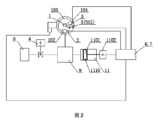
本願の第1態様は、オンラインセルフチェック機能を有するガス密度リレー(又はガス密度監視装置)を提供し、ガス密度リレー本体、ガス密度検出センサ、温度調節機構、オンラインチェック接点信号サンプリングユニット及び知能制御ユニットを含み、
前記温度調節機構は、温度調整可能な調節機構であり、前記ガス密度リレー本体に接点信号動作を発生させるように、前記ガス密度リレー本体の温度補償素子の温度昇降を調節するように配置され、
前記ガス密度検出センサは、前記ガス密度リレー本体に連通し、
前記オンラインチェック接点信号サンプリングユニットは、前記ガス密度リレー本体に直接的又は間接的に接続され、前記ガス密度リレー本体の接点が動作する時に生成される接点信号をサンプリングするように配置され、
前記知能制御ユニットは、それぞれ前記ガス密度検出センサ、前記温度調節機構及び前記オンラインチェック接点信号サンプリングユニットに接続され、前記温度調節機構の制御、圧力値収集及び温度値収集、及び/又はガス密度値収集、並びに前記ガス密度リレー本体の接点信号動作値及び/又は接点信号戻り値の検出を完了するように配置され、
ここで、前記接点信号は警報、及び/又は閉鎖を含む。
A first aspect of the present application provides a gas density relay (or a gas density monitor) with an online self-check function, comprising: a gas density relay body, a gas density detection sensor, a temperature control mechanism, an online check contact signal sampling unit and an intelligent control unit;
the temperature adjustment mechanism is a temperature adjustable adjustment mechanism and is arranged to adjust the temperature rise and fall of the temperature compensation element of the gas density relay body so as to generate a contact signal operation in the gas density relay body;
the gas density detection sensor is in communication with the gas density relay body;
the online check contact signal sampling unit is directly or indirectly connected to the gas density relay body and is arranged to sample a contact signal generated when a contact of the gas density relay body operates;
The intelligent control unit is respectively connected to the gas density detection sensor, the temperature adjustment mechanism and the online check contact signal sampling unit, and is arranged to complete the control of the temperature adjustment mechanism, the pressure value collection and the temperature value collection, and/or the gas density value collection, and the detection of the contact signal operation value and/or the contact signal return value of the gas density relay body;
Here, the contact signal includes an alarm and/or a closure.
好ましくは、前記ガス密度リレー本体は、バイメタルシート補償のガス密度リレー、ガス補償のガス密度リレー、バイメタルシート及びガス補償混合型のガス密度リレー、完全機械のガス密度リレー、デジタル型ガス密度リレー、機械及びデジタル結合型のガス密度リレー、指針表示付きのガス密度リレー、デジタル表示型ガス密度リレー、表示又は指示なしのガス密度スイッチ、SF6ガス密度リレー、SF6混合ガス密度リレー、N2ガス密度リレーを含むが、これらに限定されない。 Preferably, the gas density relay body includes, but is not limited to, a bimetallic sheet compensated gas density relay, a gas compensated gas density relay, a bimetallic sheet and gas compensated mixed gas density relay, a fully mechanical gas density relay, a digital type gas density relay, a combined mechanical and digital type gas density relay, a gas density relay with pointer display, a digital display type gas density relay, a gas density switch without display or indication, a SF6 gas density relay, a SF6 mixed gas density relay, and a N2 gas density relay.
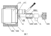
好ましくは、前記ガス密度リレー本体は、ケース、及び前記ケース内に設けられたベース、圧力検出器、温度補償素子、少なくとも1つの信号発生器を含み、ここで、前記信号発生器は、マイクロスイッチ又は磁気アシスト式電気接点を含み、前記ガス密度リレー本体は、前記信号発生器を介して接点信号を出力し、前記圧力検出器はバーデン管又は波形管を含み、前記温度補償素子は温度補償シート又はケース内に封止されたガスを採用する。 Preferably, the gas density relay body includes a case, a base provided in the case, a pressure detector, a temperature compensation element, and at least one signal generator, where the signal generator includes a microswitch or a magnetically assisted electrical contact, the gas density relay body outputs a contact signal via the signal generator, the pressure detector includes a Burden tube or a corrugated tube, and the temperature compensation element employs a temperature compensation sheet or a gas sealed in the case.
より好ましくは、前記オンラインチェック接点信号サンプリングユニットは、前記信号発生器に接続される。 More preferably, the online check contact signal sampling unit is connected to the signal generator.
より好ましくは、前記ガス密度リレー本体は表示機構を更に含み、前記表示機構は、ムーブメント、指針、ダイヤルを含み、前記ムーブメントは、前記ベース又はケース内に固定され、前記温度補償素子は他端がリンクにより前記ムーブメントに接続され、又は前記ムーブメントに直接接続され、前記指針は、前記ムーブメントに取り付けられ、かつ前記ダイヤルの前に設けられ、前記指針は前記ダイヤルと合わせてガス密度値を表示し、且つ/又は前記表示機構は表示値表示を有するデジタルデバイス又は液晶デバイスを含む。 More preferably, the gas density relay body further includes a display mechanism, the display mechanism including a movement, a pointer, and a dial, the movement is fixed within the base or case, the temperature compensation element has the other end connected to the movement by a link or directly connected to the movement, the pointer is attached to the movement and is provided in front of the dial, the pointer indicates the gas density value together with the dial, and/or the display mechanism includes a digital device or a liquid crystal device having a display value display.
より好ましくは、前記ガス密度リレー本体又は知能制御ユニットは、接触抵抗検出ユニットを更に含み、前記接触抵抗検出ユニットは、接点信号に接続され、又は信号発生器に直接接続され、オンラインチェック接点信号サンプリングユニットの制御で、ガス密度リレー本体の接点信号はその制御回路と分離され、ガス密度リレー本体の接点信号が動作する時、及び/又は接点接触抵抗を検出する指令を受信した時に、接触抵抗検出ユニットはガス密度リレー本体の接点接触抵抗値を検出することができる。 More preferably, the gas density relay body or the intelligent control unit further includes a contact resistance detection unit, which is connected to a contact signal or directly connected to a signal generator, and under the control of the online check contact signal sampling unit, the contact signal of the gas density relay body is separated from its control circuit, and when the contact signal of the gas density relay body operates and/or when a command to detect the contact resistance of the contact is received, the contact resistance detection unit can detect the contact resistance value of the gas density relay body.
より好ましくは、前記ガス密度リレー本体又は知能制御ユニットは、絶縁抵抗検出ユニットを更に含み、前記絶縁抵抗検出ユニットは、接点信号に接続され、又は信号発生器に直接接続され、オンラインチェック接点信号サンプリングユニットの制御で、ガス密度リレー本体の接点信号はその制御回路と分離され、ガス密度リレー本体の接点信号が動作する時、及び/又は接点絶縁抵抗を検出する指令を受信した時に、絶縁抵抗検出ユニットはガス密度リレー本体の接点絶縁抵抗値を検出することができる。 More preferably, the gas density relay body or the intelligent control unit further includes an insulation resistance detection unit, which is connected to a contact signal or directly connected to a signal generator, and under the control of the online check contact signal sampling unit, the contact signal of the gas density relay body is separated from its control circuit, and when the contact signal of the gas density relay body operates and/or when a command to detect the contact insulation resistance is received, the insulation resistance detection unit can detect the contact insulation resistance value of the gas density relay body.
好ましくは、前記温度調節機構は加熱素子であり、或いは、
前記温度調節機構は、加熱素子、保温材、温度コントローラー、温度検出器、温度調節機構ハウジングを含み、或いは、
前記温度調節機構は、加熱素子と温度コントローラーを含み、或いは、
前記温度調節機構は、加熱素子、加熱電力レギュレーター及び温度コントローラーを含み、或いは、
前記温度調節機構は、加熱素子、冷却素子、加熱電力レギュレーター及び温度コントローラーを含み、或いは、
前記温度調節機構は、加熱素子、加熱電力レギュレーター及び恒温コントローラーを含み、或いは、
前記温度調節機構は、加熱素子、温度コントローラー、温度検出器を含み、或いは、
前記温度調節機構は加熱素子であり、前記加熱素子は温度補償素子の近傍に設けられ、或いは、
前記温度調節機構はマイクロ恒温ボックスであり、
ここで、前記加熱素子の数は少なくとも1つであり、前記加熱素子はシリコーンゴム加熱器、抵抗線、電熱ベルト、電熱棒、熱風機、赤外線加熱デバイス、半導体のうちの一種を含むが、これらに限定されなく、
前記温度コントローラーは、前記加熱素子に接続され、加熱素子の加熱温度を制御するためのものであり、前記温度コントローラーは、PIDコントローラー、PIDとファジー制御を組み合わせたコントローラー、周波数変換コントローラー、PLCコントローラーのうちの一種を含むが、これらに限定されない。
Preferably, the temperature adjustment mechanism is a heating element; or
the temperature adjustment mechanism includes a heating element, a thermal insulation material, a temperature controller, a temperature detector, and a temperature adjustment mechanism housing; or
The temperature adjustment mechanism includes a heating element and a temperature controller; or
The temperature adjustment mechanism includes a heating element, a heating power regulator, and a temperature controller; or
The temperature adjustment mechanism includes a heating element, a cooling element, a heating power regulator, and a temperature controller; or
The temperature control mechanism includes a heating element, a heating power regulator, and a constant temperature controller; or
The temperature adjustment mechanism may include a heating element, a temperature controller, or a temperature detector; or
The temperature adjustment mechanism is a heating element, and the heating element is disposed adjacent to the temperature compensation element; or
The temperature control mechanism is a micro thermostatic box,
Here, the number of the heating elements is at least one, and the heating elements include, but are not limited to, a silicone rubber heater, a resistance wire, an electric heating belt, an electric heating rod, a hot air blower, an infrared heating device, and a semiconductor;
The temperature controller is connected to the heating element and is for controlling the heating temperature of the heating element, and the temperature controller can include, but is not limited to, a PID controller, a controller combining PID and fuzzy control, a frequency conversion controller, and a PLC controller.
より好ましくは、前記温度調節機構における加熱素子は、少なくとも電力が同じ又は異なる2つの加熱素子、或いは加熱電力が調整可能な加熱素子を含む。 More preferably, the heating elements in the temperature adjustment mechanism include at least two heating elements with the same or different power, or a heating element with adjustable heating power.
より好ましくは、少なくとも2つの前記加熱素子の設置位置は同じであっても異なってもよく、必要に応じて合理的に設置されてもよい。 More preferably, the installation positions of at least two of the heating elements may be the same or different, and may be rationally installed as required.
より好ましくは、前記温度調節機構の温度昇降方式は多段制御である。 More preferably, the temperature adjustment mechanism uses a multi-stage temperature control method.
好ましくは、前記温度調節機構は知能制御ユニットの制御により、ガス密度リレー接点信号の動作値を測定する時、動作値に近い時に温度変化速度が一秒当たり1.0℃以下である(又は必要に応じて該要求を設定する)と、すなわち温度が安定して上昇し又は下降するように要求される。 Preferably, the temperature adjustment mechanism is controlled by an intelligent control unit to measure the operating value of the gas density relay contact signal and to request that the temperature change rate be less than 1.0°C per second (or to set the requirement as necessary) when approaching the operating value, i.e., that the temperature rises or falls steadily.
好ましくは、前記ガス密度リレー(又はガス密度監視装置)は相互自己校正ユニットを更に含み、知能制御ユニットは、相互自己校正ユニットによって検出されたデータを比較することにより、ガス密度リレーのメンテナンスフリーを実現し、或いは、知能制御ユニット及び相互自己校正ユニットにより検出されたデータを比較することにより、ガス密度リレーのメンテナンスフリーを実現する。 Preferably, the gas density relay (or gas density monitoring device) further includes a mutual self-calibration unit, and the intelligent control unit realizes a maintenance-free gas density relay by comparing data detected by the mutual self-calibration unit, or realizes a maintenance-free gas density relay by comparing data detected by the intelligent control unit and the mutual self-calibration unit.
好ましくは、前記知能制御ユニットは、深度計算ユニットを更に含み、深度計算ユニットは環境温度値、電気機器のガス密度値又は圧力値に基づいて、ガス圧力-温度特性により、チャック必要がある前記ガス密度リレーに対してチェック初期密度が適切なガス源を提供し、又は、前記知能制御ユニットは、チェック時の環境温度値、電気機器のエアチャンバーのガス圧力値、前記ガス密度リレーのチェック必要がある温度値に基づいて、ガス圧力-温度特性により、チェック必要がある前記ガス密度リレーに対してチェック初期密度が適切なガス源を提供することができる。 Preferably, the intelligent control unit further includes a depth calculation unit, which provides a gas source with an appropriate initial density for checking the gas density relay that needs to be chucked according to gas pressure-temperature characteristics based on the environmental temperature value, the gas density value or pressure value of the electrical equipment, or the intelligent control unit can provide a gas source with an appropriate initial density for checking the gas density relay according to gas pressure-temperature characteristics based on the environmental temperature value at the time of checking, the gas pressure value of the air chamber of the electrical equipment, and the temperature value of the gas density relay that needs to be checked.
好ましくは、前記ガス密度検出センサは前記ガス密度リレー本体に設けられ、或いは、前記温度調節機構は、前記ガス密度リレー本体内又は本体外に設けられ、或いは、前記ガス密度検出センサ、前記オンラインチェック接点信号サンプリングユニット及び前記知能制御ユニットは、前記ガス密度リレー本体に設けられ、或いは、前記温度調節機構、前記ガス密度検出センサ、前記オンラインチェック接点信号サンプリングユニット及び前記知能制御ユニットは、前記ガス密度リレー本体に設けられる。 Preferably, the gas density detection sensor is provided in the gas density relay body, or the temperature adjustment mechanism is provided inside or outside the gas density relay body, or the gas density detection sensor, the online check contact signal sampling unit, and the intelligent control unit are provided in the gas density relay body, or the temperature adjustment mechanism, the gas density detection sensor, the online check contact signal sampling unit, and the intelligent control unit are provided in the gas density relay body.
より好ましくは、前記ガス密度リレー本体、前記ガス密度検出センサは一体化構造であり、好ましくは、前記ガス密度リレー本体、前記ガス密度検出センサは一体化構造の遠隔伝送式ガス密度リレーである。 More preferably, the gas density relay body and the gas density detection sensor are of an integrated structure, and preferably, the gas density relay body and the gas density detection sensor are of an integrated structure, which is a remote transmission type gas density relay.
好ましくは、前記ガス密度検出センサは一体化構造である。 Preferably, the gas density detection sensor is an integrated structure.
より好ましくは、前記ガス密度検出センサは一体化構造のガス密度トランスミッターであり、好ましくは、前記オンラインチェック接点信号サンプリングユニット、前記知能制御ユニットは前記ガス密度トランスミッターに設けられる。 More preferably, the gas density detection sensor is an integrated gas density transmitter, and preferably, the online check contact signal sampling unit and the intelligent control unit are provided in the gas density transmitter.
好ましくは、前記ガス密度検出センサは、少なくとも1つの圧力センサ及び少なくとも1つの温度センサを含み、或いは、前記ガス密度検出センサは圧力センサ及び温度センサで構成されたガス密度トランスミッターであり、或いは、前記ガス密度検出センサはクォーツ音叉テクノロジーを採用する密度検出センサである。 Preferably, the gas density detection sensor includes at least one pressure sensor and at least one temperature sensor, or the gas density detection sensor is a gas density transmitter composed of a pressure sensor and a temperature sensor, or the gas density detection sensor is a density detection sensor employing quartz tuning fork technology.
より好ましくは、前記圧力センサは前記ガス密度リレー本体のガス路に取り付けられる。 More preferably, the pressure sensor is attached to the gas path of the gas density relay body.
より好ましくは、前記温度センサは、前記ガス密度リレー本体のガス路上又はガス路外、或いは前記ガス密度リレー本体内、或いは前記ガス密度リレー本体内の温度補償素子の近傍、或いは前記ガス密度リレー本体外に取り付けられる。 More preferably, the temperature sensor is mounted on or outside the gas path of the gas density relay body, or inside the gas density relay body, or near a temperature compensation element in the gas density relay body, or outside the gas density relay body.
より好ましくは、温度センサは、熱電対、サーミスタ、半導体式であってもよく、接触式及び非接触式であってもよく、熱抵抗及び熱電対であってもよい。 More preferably, the temperature sensor may be a thermocouple, a thermistor, a semiconductor type, a contact type and a non-contact type, a thermal resistor and a thermocouple.
より好ましくは、少なくとも1つの前記温度センサは、前記ガス密度リレー本体の温度補償素子の近傍に設けられ、又は温度補償素子に設けられ、又は前記温度補償素子に集積される。好ましくは、少なくとも1つの前記温度センサは前記ガス密度リレー本体の圧力検出器の温度補償素子に近接する一端に設けられる。 More preferably, the at least one temperature sensor is provided near the temperature compensation element of the gas density relay body, or is provided on the temperature compensation element, or is integrated into the temperature compensation element. Preferably, the at least one temperature sensor is provided on one end of the gas density relay body that is close to the temperature compensation element of the pressure detector.
より好ましくは、前記圧力センサは、相対圧力センサ、及び/又は絶対圧力センサを含むが、これらに限定されない。 More preferably, the pressure sensor includes, but is not limited to, a relative pressure sensor and/or an absolute pressure sensor.
さらに、前記圧力センサが絶対圧力センサである場合に、絶対圧力値で表し、そのチェック結果は対応する20℃の絶対圧力値であり、相対圧力値で表し、そのチェック結果は対応する20℃の相対圧力値に換算し、
前記圧力センサが相対圧力センサである場合に、相対圧力値で表し、そのチェック結果は対応する20℃の相対圧力値であり、絶対圧力値で表し、そのチェック結果は対応する20℃の絶対圧力値に換算し、
前記絶対圧力値と前記相対圧力値との間の換算関係は以下のとおりである。
P絶対圧力=P相対圧力+P標準大気圧。
Furthermore, when the pressure sensor is an absolute pressure sensor, the pressure is expressed as an absolute pressure value, and the check result is the corresponding absolute pressure value at 20° C. When the pressure sensor is an absolute pressure sensor, the pressure is expressed as a relative pressure value, and the check result is converted into the corresponding relative pressure value at 20° C.
When the pressure sensor is a relative pressure sensor, the pressure sensor is expressed as a relative pressure value, and the check result is a corresponding relative pressure value at 20° C. When the pressure sensor is expressed as an absolute pressure value, the check result is converted into a corresponding absolute pressure value at 20° C.;
The conversion relationship between the absolute pressure value and the relative pressure value is as follows:
P absolute pressure = P relative pressure + P standard atmospheric pressure .
さらに、前記圧力センサは拡散シリコン圧力センサ、MEMS圧力センサ、チップ式圧力センサ、コイル誘導圧力センサ(例えばバーデン管に誘導コイルが付いた圧力センサ)、抵抗圧力センサ(例えばバーデン管に滑り線抵抗が付いた圧力センサ)であってもよく、アナログ量圧力センサであってもよく、デジタル量圧力センサであってもよい。 Furthermore, the pressure sensor may be a diffused silicon pressure sensor, a MEMS pressure sensor, a chip-based pressure sensor, a coil-inductive pressure sensor (e.g., a pressure sensor with an inductive coil in a Burden tube), a resistive pressure sensor (e.g., a pressure sensor with a sliding line resistor in a Burden tube), an analog quantity pressure sensor, or a digital quantity pressure sensor.
好ましくは、前記オンラインチェック接点信号サンプリングユニットと前記知能制御ユニットは一体に設けられる。 Preferably, the online check contact signal sampling unit and the intelligent control unit are integrally provided.
より好ましくは、前記オンラインチェック接点信号サンプリングユニットと前記知能制御ユニットは1つのキャビティ又はケース内に封止される。 More preferably, the online check contact signal sampling unit and the intelligent control unit are sealed within one cavity or case.
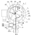
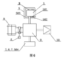
好ましくは、前記ガス密度リレー(又はガス密度監視装置)は、圧力調節機構を更に含み、前記圧力調節機構のガス路は、前記ガス密度リレー本体に連通し、前記圧力調節機構は、前記ガス密度リレー本体の圧力昇降を調節するように配置され、さらに温度調節機構と嵌合し、かつ/又は結合することで、前記ガス密度リレー本体に接点信号動作を発生させ、前記知能制御ユニットは前記圧力調節機構に接続され、前記圧力調節機構の制御を完了し、或いは、
加熱デバイスを更に含み、前記知能制御ユニットは前記加熱デバイスに接続され、或いは、
エアチャンバー及び加熱デバイスを更に含み、前記エアチャンバーは前記ガス密度リレー本体に連通し、前記加熱デバイスは前記エアチャンバーの外部又は内部に設けられ、前記知能制御ユニットは前記加熱デバイスに接続される。
Preferably, the gas density relay (or gas density monitor) further includes a pressure adjusting mechanism, the gas path of the pressure adjusting mechanism is connected to the gas density relay body, the pressure adjusting mechanism is arranged to adjust the pressure rise and fall of the gas density relay body, and is further fitted and/or coupled with a temperature adjusting mechanism to generate a contact signal operation in the gas density relay body, and the intelligent control unit is connected to the pressure adjusting mechanism and completes the control of the pressure adjusting mechanism; or
Further comprising a heating device, the intelligent control unit being connected to the heating device; or
The gas density relay further includes an air chamber and a heating device, the air chamber communicates with the gas density relay body, the heating device is disposed outside or inside the air chamber, and the intelligent control unit is connected to the heating device.
より好ましくは、前記圧力調節機構のガス路は前記ガス密度リレー本体の圧力検出器と連通する。 More preferably, the gas path of the pressure adjustment mechanism communicates with the pressure detector of the gas density relay body.
より好ましくは、前記圧力調節機構は1つのキャビティ又はケース内に封止される。 More preferably, the pressure adjustment mechanism is sealed within a single cavity or case.
より好ましくは、チェック時、前記圧力調節機構は密閉エアチャンバーであり、前記密閉エアチャンバーの外部又は内部に加熱素子、及び/又は冷却素子が設けられ、前記加熱素子により加熱し、かつ/又は前記冷却素子により冷却し、前記密閉エアチャンバー内のガスの温度変化をもたらし、さらに前記ガス密度リレーの圧力昇降を完了する。 More preferably, during checking, the pressure adjustment mechanism is a sealed air chamber, a heating element and/or a cooling element are provided outside or inside the sealed air chamber, and the heating element heats and/or the cooling element cools the gas in the sealed air chamber, causing a change in temperature, and further completing the pressure increase/decrease of the gas density relay.
さらに、前記加熱素子、及び/又は前記冷却素子は半導体である。 Furthermore, the heating element and/or the cooling element are semiconductors.
さらに、前記圧力調節機構は保温材を更に含み、前記保温材は前記密閉エアチャンバーの外部に設けられる。 Furthermore, the pressure adjustment mechanism further includes a thermal insulation material, which is provided outside the sealed air chamber.
より好ましくは、チェック時に、前記圧力調節機構は一端が開口したキャビティであり、前記キャビティの他端は前記ガス密度リレー本体に連通し、前記キャビティ内にピストンがあり、前記ピストンの一端に調節ロッドが接続され、前記調節ロッドの外端は駆動部材に接続され、前記ピストンの他端は前記開口内に伸び込み、かつ前記キャビティの内壁と密封接触し、前記駆動部材は前記調節ロッドを駆動してさらに前記ピストンが前記キャビティ内を移動するように連動させる。 More preferably, during checking, the pressure adjustment mechanism is a cavity with one open end, the other end of the cavity is connected to the gas density relay body, a piston is present within the cavity, an adjustment rod is connected to one end of the piston, the outer end of the adjustment rod is connected to a drive member, the other end of the piston extends into the opening and is in sealing contact with the inner wall of the cavity, and the drive member drives the adjustment rod to further engage the piston to move within the cavity.
より好ましくは、チェック時に、前記圧力調節機構は密閉エアチャンバーであり、前記密閉エアチャンバーの内部にピストンが設けられ、前記ピストンは前記密閉エアチャンバーの内壁と密封接触し、前記密閉エアチャンバーの外部に駆動部材が設けられ、前記駆動部材は電磁力により前記ピストンが前記キャビティ内を移動するように駆動する。 More preferably, during checking, the pressure adjustment mechanism is a sealed air chamber, a piston is provided inside the sealed air chamber, the piston is in sealed contact with the inner wall of the sealed air chamber, a driving member is provided outside the sealed air chamber, and the driving member drives the piston to move within the cavity by electromagnetic force.
より好ましくは、前記圧力調節機構は一端が駆動部材に接続されたエアバッグであり、前記エアバッグは前記駆動部材の駆動で体積変化が発生し、前記エアバッグは前記ガス密度リレー本体に連通する。 More preferably, the pressure adjustment mechanism is an airbag having one end connected to a drive member, the volume of the airbag changes when the drive member is driven, and the airbag is connected to the gas density relay body.
より好ましくは、前記圧力調節機構は波形管であり、前記波形管の一端は前記ガス密度リレー本体に連通し、前記波形管の他端は前記駆動部材の駆動で伸縮する。 More preferably, the pressure adjustment mechanism is a corrugated tube, one end of which is connected to the gas density relay body, and the other end of which is expanded and contracted by the drive member.
上記圧力調節機構における前記駆動部材は、磁力、電機(可変周波数電機又はステッピング電機)、往復運動機構、カルノー循環機構、空気圧素子のうちの一種を含むが、これらに限定されない。 The driving member in the pressure adjustment mechanism includes, but is not limited to, a magnetic force, an electric motor (variable frequency electric motor or stepping electric motor), a reciprocating mechanism, a Carnot circulation mechanism, or a pneumatic element.
より好ましくは、前記圧力調節機構はリリースバルブである。 More preferably, the pressure adjustment mechanism is a release valve.
さらに、前記圧力調節機構はガスリリース流量を制御する流量弁を更に含む。 Furthermore, the pressure adjustment mechanism further includes a flow valve that controls the gas release flow rate.
さらに、前記リリースバルブは電磁弁又は電動弁、或いは他の電気又はガスの方式で実現されるリリースバルブである。 Furthermore, the release valve may be a solenoid valve, an electric valve, or any other electrical or gas type release valve.
より好ましくは、前記圧力調節機構は圧縮機である。 More preferably, the pressure adjustment mechanism is a compressor.
より好ましくは、前記圧力調節機構はポンプである。 More preferably, the pressure adjustment mechanism is a pump.
さらに、前記ポンプは、圧力発生ポンプ、加圧ポンプ、電動エアポンプ、電磁エアポンプのうちの一種を含むが、これらに限定されない。 Furthermore, the pump may include, but is not limited to, a pressure generating pump, a pressurizing pump, an electric air pump, or an electromagnetic air pump.
より好ましくは、前記ガス密度リレー(又はガス密度監視装置)は弁を更に含み、前記弁の一端に電気機器に連通する接続ポートが設けられ、前記弁は他端が前記圧力調節機構、前記ガス密度リレー本体のガス路に連通する。 More preferably, the gas density relay (or gas density monitor) further includes a valve, one end of which is provided with a connection port that communicates with an electrical device, and the other end of which is connected to the pressure adjustment mechanism and the gas path of the gas density relay body.
さらに、前記弁は前記知能制御ユニットに接続され、前記知能制御ユニットの制御で前記弁の閉じ又は開きを実現する。 Furthermore, the valve is connected to the intelligent control unit, and the valve is closed or opened under the control of the intelligent control unit.
さらに、前記弁は、他端がガス密度リレー本体のベース、圧力検出器に連通し、又は前記弁は他端が前記圧力調節機構のガス路に接続されることで、前記弁を前記ベース、前記圧力検出器に連通する。 Furthermore, the other end of the valve is connected to the base of the gas density relay body and the pressure detector, or the other end of the valve is connected to the gas path of the pressure adjustment mechanism, thereby connecting the valve to the base and the pressure detector.
さらに、前記弁は電動弁である。 Furthermore, the valve is an electrically operated valve.
さらに、前記弁は電磁弁である。 Furthermore, the valve is a solenoid valve.
さらに、前記弁は永久磁石式電磁弁である。 Furthermore, the valve is a permanent magnet solenoid valve.
さらに、前記弁はピエゾバルブ、又は温度制御の弁であり、或いは、スマート記憶材料で製造され、電気加熱で開閉する新型弁である。 Furthermore, the valve may be a piezoelectric valve, or a temperature-controlled valve, or a new type of valve made of smart memory material that opens and closes by electrical heating.
さらに、前記弁はホースを折り曲げ、又は挟む方式で閉じ又は開くことを実現する。 Furthermore, the valve can be closed or opened by bending or pinching the hose.
さらに、前記弁は1つのキャビティ又はケース内に封止される。 Furthermore, the valve is sealed within a cavity or case.
さらに、前記弁及び前記圧力調節機構は1つのキャビティ又はケース内に封止される。 Furthermore, the valve and the pressure adjustment mechanism are sealed within a single cavity or case.
さらに、前記弁のガス路の両側にはそれぞれ圧力センサが設けられる。 In addition, pressure sensors are provided on both sides of the gas passage of the valve.
さらに、前記弁は電気機器接続継手により前記電気機器に連通する。 Furthermore, the valve is connected to the electrical equipment via an electrical equipment connection joint.
さらに、前記ガス密度リレー(又はガス密度監視装置)は、自己密封弁を更に含み、前記自己密封弁は、前記電気機器と前記弁との間に取り付けられ、或いは、前記弁は前記電気機器と前記自己密封弁との間に取り付けられる。 Furthermore, the gas density relay (or gas density monitor) further includes a self-sealing valve, and the self-sealing valve is mounted between the electrical equipment and the valve, or the valve is mounted between the electrical equipment and the self-sealing valve.
さらに、前記ガス密度リレー(又はガス密度監視装置)は、ガス補充ポートを更に含み、前記ガス補充ポートは、前記圧力調節機構に設けられ、或いは、前記ガス補充ポートは前記電気機器に設けられ、或いは、前記ガス補充ポートは、前記電気機器と前記弁との間に設けられ、或いは、前記ガス補充ポートは第2接続管に設けられ、前記第2接続管は前記弁と前記圧力調節機構のガス路に連通し、又は、前記第2接続管は前記弁と前記ガス密度リレー本体とに連通する。 Furthermore, the gas density relay (or gas density monitor) further includes a gas refill port, the gas refill port being provided in the pressure adjustment mechanism, or the gas refill port being provided in the electrical device, or the gas refill port being provided between the electrical device and the valve, or the gas refill port being provided in a second connecting tube, the second connecting tube being connected to the gas path of the valve and the pressure adjustment mechanism, or the second connecting tube being connected to the valve and the gas density relay body.
好ましくは、前記電気機器はSF6ガス電気機器、SF6混合ガス電気機器、環境保護型ガス電気機器、又は他の絶縁ガス電気機器を含む。 Preferably, the electrical equipment includes SF6 gas electrical equipment, SF6 mixed gas electrical equipment, environmentally friendly gas electrical equipment, or other insulated gas electrical equipment.
具体的には、前記電気機器は、GIS、GIL、PASS、遮断器、変流器、計器用変圧器、変圧器、ガス充填キャビネット、リングメインキャビネットを含む。 Specifically, the electrical equipment includes GIS, GIL, PASS, circuit breakers, current transformers, potential transformers, transformers, gas-filled cabinets, and ring main cabinets.
好ましくは、前記オンラインチェック接点信号サンプリングユニットによる前記ガス密度リレー本体の接点信号のサンプリングは、下記を満たす。前記オンラインチェック接点信号サンプリングユニットは独立した少なくとも一組のサンプリング接点を有し、同時に少なくとも1つの接点に対してチェックを自動的に完了するとともに、接点を交換し又は接点を再選択する必要がなく、連続的に測定することができ、ここで、前記接点は、警報接点、警報接点+閉鎖接点、警報接点+閉鎖1接点+閉鎖2接点、警報接点+閉鎖接点+過電圧接点のうちの一種を含むが、これらに限定されない。 Preferably, the sampling of the contact signal of the gas density relay body by the online check contact signal sampling unit satisfies the following: The online check contact signal sampling unit has at least one set of independent sampling contacts, automatically completes a check on at least one contact at a time, and can continuously measure without the need to replace or reselect the contacts, where the contacts include, but are not limited to, one of the following: alarm contact, alarm contact + close contact, alarm contact + close 1 contact + close 2 contact, and alarm contact + close contact + overvoltage contact.
好ましくは、前記オンラインチェック接点信号サンプリングユニットの前記ガス密度リレー本体の接点信号動作値又はその切替値に対するテスト電圧は24V以上であり、即ちチェック時に、接点信号の対応する端子の間に24V以上の電圧を印加する。 Preferably, the test voltage for the contact signal operating value or its switching value of the gas density relay body of the online check contact signal sampling unit is 24 V or more, i.e., during the check, a voltage of 24 V or more is applied between the corresponding terminals of the contact signal.
好ましくは、前記知能制御ユニットは、前記ガス密度検出センサにより収集されたガス密度値を取得し、或いは、前記知能制御ユニットは前記ガス密度検出センサにより収集された圧力値及び温度値を取得し、前記ガス密度リレーのガス密度リレー本体に対するオンライン監視を完了し、即ち前記ガス密度リレーの監視される電気機器のガス密度に対するオンライン監視を完了する。 Preferably, the intelligent control unit obtains the gas density value collected by the gas density detection sensor, or the intelligent control unit obtains the pressure value and temperature value collected by the gas density detection sensor, and completes online monitoring of the gas density relay body of the gas density relay, i.e., completes online monitoring of the gas density of the electrical equipment monitored by the gas density relay.
より好ましくは、前記知能制御ユニットは、平均法(平均値法)を採用して前記ガス密度値を計算し、前記平均法は以下のとおりである。設定された時間間隔内に、収集頻度を設定し、全ての収集して得られた異なる時点のN個のガス密度値に平均値計算処理を行い、そのガス密度値を取得し、或いは、設定された時間間隔内に、温度間隔刻み幅を設定し、全ての温度範囲で収集して得られたN個の異なる温度値に対応する密度値に平均値計算処理を行い、そのガス密度値を取得し、或いは、設定された時間間隔内に、圧力間隔刻み幅を設定し、全ての圧力変化範囲で収集して得られたN個の異なる圧力値に対応する密度値に平均値計算処理を行い、そのガス密度値を取得し、ここで、Nは1以上の正整数である。 More preferably, the intelligent control unit adopts an averaging method (average value method) to calculate the gas density value, and the averaging method is as follows: within a set time interval, a collection frequency is set, and an average value calculation process is performed on all collected and obtained N gas density values at different time points to obtain the gas density value; alternatively, within a set time interval, a temperature interval step width is set, and an average value calculation process is performed on density values corresponding to N different temperature values collected and obtained in all temperature ranges to obtain the gas density value; alternatively, within a set time interval, a pressure interval step width is set, and an average value calculation process is performed on density values corresponding to N different pressure values collected and obtained in all pressure change ranges to obtain the gas density value, where N is a positive integer equal to or greater than 1.
好ましくは、前記知能制御ユニットは、前記ガス密度リレー本体に接点信号動作又は切り替えが発生する時に、前記ガス密度検出センサが収集したガス密度値を取得し、前記ガス密度リレーのオンラインチェックを完了し、或いは、
前記知能制御ユニットは、前記ガス密度リレー本体に接点信号動作又は切り替えが発生する時に前記ガス密度検出センサが収集した圧力値及び温度値を取得するとともに、ガス圧力-温度特性に応じて20℃に対応する圧力値であるガス密度値に換算し、前記ガス密度リレーのオンラインチェックを完了する。
Preferably, the intelligent control unit obtains the gas density value collected by the gas density detection sensor when the gas density relay body generates a contact signal operation or switching, and completes an online check of the gas density relay; or
The intelligent control unit obtains the pressure value and temperature value collected by the gas density detection sensor when a contact signal operation or switching occurs in the gas density relay body, and converts it into a gas density value, which is a pressure value corresponding to 20°C, according to the gas pressure-temperature characteristics, to complete an online check of the gas density relay.
好ましくは、前記ガス密度リレー本体は、比較密度値出力信号を有し、該比較密度値出力信号は、前記知能制御ユニットに接続され、或いは、前記ガス密度リレー本体は、比較圧力値出力信号を有し、該比較圧力値出力信号は、前記知能制御ユニットに接続される。 Preferably, the gas density relay body has a comparative density value output signal, which is connected to the intelligent control unit, or the gas density relay body has a comparative pressure value output signal, which is connected to the intelligent control unit.
好ましくは、前記知能制御ユニットは、マイクロプロセッサの組み込みシステムの組み込みアルゴリズム及び制御プログラムに基づいて、チェックプロセス全体を自動的に制御し、全ての周辺機器、論理及び入出力を含む。 Preferably, the intelligent control unit automatically controls the entire checking process based on the built-in algorithms and control programs of the microprocessor embedded system, including all peripherals, logic and inputs/outputs.
より好ましくは、前記知能制御ユニットは、汎用コンピュータ、産業用コンピュータ、ARMチップ、AIチップ、CPU、MCU、FPGA、PLCなど、産業用制御メインボード、組み込み主制御基板などの組み込みアルゴリズム及び制御プログラムに基づいて、チェックプロセス全体を自動的に制御し、全ての周辺機器、論理及び入出力を含む。 More preferably, the intelligent control unit automatically controls the entire checking process based on the built-in algorithm and control program of general-purpose computers, industrial computers, ARM chips, AI chips, CPUs, MCUs, FPGAs, PLCs, industrial control mainboards, built-in main control boards, etc., and includes all peripherals, logic and inputs and outputs.
好ましくは、前記知能制御ユニットに電気インタフェースが設けられ、前記電気インタフェースはテストデータの記憶、及び/又はテストデータの導出、及び/又はテストデータの印刷、及び/又はホストコンピューターとのデータ通信、及び/又はアナログ量、デジタル量情報の入力を完了する。 Preferably, the intelligent control unit is provided with an electrical interface, which completes the storage of test data, and/or the derivation of test data, and/or the printing of test data, and/or data communication with a host computer, and/or the input of analog quantity and digital quantity information.
より好ましくは、前記ガス密度リレー(又はガス密度監視装置)はガス密度リレーの基本的な情報入力をサポートし、前記基本的な情報は出荷番号、精度要求、定格パラメータ、製造所、稼働位置のうちの一種又は複数種を含むが、これらに限定されない。 More preferably, the gas density relay (or gas density monitor) supports input of basic information for the gas density relay, the basic information including, but not limited to, one or more of the following: shipping number, accuracy requirements, rated parameters, place of manufacture, and operating location.
好ましくは、前記知能制御ユニットはテストデータ、及び/又はチェック結果の遠距離伝送を実現する通信モジュールを更に含む。 Preferably, the intelligent control unit further includes a communication module for enabling long-distance transmission of test data and/or check results.
より好ましくは、前記通信モジュールの通信方式は有線通信又は無線通信方式である。 More preferably, the communication method of the communication module is a wired communication or wireless communication method.
さらに、前記有線通信方式は、RS232バス、RS485バス、CAN-BUSバス、4-20mA、Hart、IIC、SPI、Wire、同軸ケーブル、PLC電力キャリア、ケーブルのうちの一種又は複数種を含むが、これらに限定されない。 Furthermore, the wired communication method includes, but is not limited to, one or more of the following: RS232 bus, RS485 bus, CAN-BUS bus, 4-20mA, Hart, IIC, SPI, Wire, coaxial cable, PLC power carrier, cable.
さらに、前記無線通信方式は、NB-IOT、2G/3G/4G/5G、WIFI、ブルートゥース(登録商標)、Lora、Lorawan、Zigbee、赤外線、超音波、音波、衛星、光波、量子通信、ソナーのうちの一種又は複数種を含むが、これらに限定されない。 Furthermore, the wireless communication method includes, but is not limited to, one or more of NB-IOT, 2G/3G/4G/5G, WIFI, Bluetooth (registered trademark), Lora, Lorawan, Zigbee, infrared, ultrasonic, sound wave, satellite, light wave, quantum communication, and sonar.
好ましくは、前記知能制御ユニットにはクロックが更に設けられ、前記クロックは、前記ガス密度リレーのチェック時間を定期的に設定し、又はテスト時間を記録し、又はイベント時間を記録するために用いるように配置される。 Preferably, the intelligent control unit is further provided with a clock, the clock being arranged to be used to periodically set a check time for the gas density relay or to record a test time or to record an event time.
好ましくは、前記知能制御ユニットの制御は現場、及び/又はバックグラウンドにより制御される。 Preferably, the intelligent control unit is controlled locally and/or in the background.
より好ましくは、前記ガス密度リレー(又はガス密度監視装置)は、前記バックグラウンドの設置又は指令に基づいて、前記ガス密度リレーのオンラインチェックを完了し、或いは、設定された前記ガス密度リレーのチェック時間に基づいて、前記ガス密度リレーのオンラインチェックを完了する。 More preferably, the gas density relay (or gas density monitor) completes an online check of the gas density relay based on the background installation or command, or completes an online check of the gas density relay based on a set check time of the gas density relay.
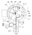
好ましくは、前記ガス密度リレー(又はガス密度監視装置)は、多方継手を更に含み、前記ガス密度リレー本体、前記温度調節機構は、前記多方継手に設けられ、或いは、前記温度調節機構は前記多方継手に固定され、或いは、前記ガス密度リレー本体、ガス密度検出センサ、前記温度調節機構は、前記多方継手に設けられる。 Preferably, the gas density relay (or gas density monitoring device) further includes a multi-way joint, and the gas density relay body and the temperature adjustment mechanism are provided in the multi-way joint, or the temperature adjustment mechanism is fixed to the multi-way joint, or the gas density relay body, the gas density detection sensor, and the temperature adjustment mechanism are provided in the multi-way joint.
より好ましくは、少なくとも2つのガス密度リレー本体、少なくとも2つの温度調節機構、少なくとも2つのオンラインチェック接点信号サンプリングユニット及び1つの知能制御ユニット、1つのガス密度検出センサは、前記ガス密度リレーのオンラインチェックを完了し、或いは、少なくとも2つのガス密度リレー本体、少なくとも2つの多方継手、少なくとも2つの温度調節機構、少なくとも2つのオンラインチェック接点信号サンプリングユニット、少なくとも2つの知能制御ユニット及び1つのガス密度検出センサは、前記ガス密度リレーのオンラインチェックを完了し、或いは、少なくとも2つのガス密度リレー本体、少なくとも2つの多方継手、少なくとも2つの温度調節機構、少なくとも2つのオンラインチェック接点信号サンプリングユニット、少なくとも2つのガス密度検出センサ及び1つの知能制御ユニットは、前記ガス密度リレーのオンラインチェックを完了する。 More preferably, at least two gas density relay bodies, at least two temperature adjustment mechanisms, at least two online check contact signal sampling units, and one intelligent control unit, and one gas density detection sensor complete the online check of the gas density relay, or at least two gas density relay bodies, at least two multi-way joints, at least two temperature adjustment mechanisms, at least two online check contact signal sampling units, at least two intelligent control units, and one gas density detection sensor complete the online check of the gas density relay, or at least two gas density relay bodies, at least two multi-way joints, at least two temperature adjustment mechanisms, at least two online check contact signal sampling units, at least two gas density detection sensors, and one intelligent control unit complete the online check of the gas density relay.
より好ましくは、前記ガス密度リレー(又はガス密度監視装置)は第1接続管を更に含み、前記圧力調節機構のガス路は、前記第1接続管を介して前記ガス密度リレー本体に連通し、前記多方継手の第1インタフェースは前記第1接続管の前記ガス密度リレー本体、前記圧力調節機構の間の箇所に連通する。 More preferably, the gas density relay (or gas density monitor) further includes a first connecting pipe, the gas path of the pressure adjustment mechanism is connected to the gas density relay body via the first connecting pipe, and the first interface of the multi-way joint is connected to a location of the first connecting pipe between the gas density relay body and the pressure adjustment mechanism.
より好ましくは、前記弁は前記多方継手の第2インタフェースに連通するとともに、前記多方継手により前記ガス密度リレー本体に連通する。 More preferably, the valve communicates with the second interface of the multi-way joint and communicates with the gas density relay body through the multi-way joint.
より好ましくは、前記弁と電気機器とが連通するポートは、前記多方継手の第1インタフェースに連通し、前記ガス密度リレー本体は前記弁により前記多方継手に連通し、前記多方継手の第2インタフェースは電気機器を接続するために用いる。 More preferably, the port through which the valve and the electrical device communicate is connected to a first interface of the multi-way joint, the gas density relay body is connected to the multi-way joint by the valve, and the second interface of the multi-way joint is used to connect the electrical device.
より好ましくは、温度センサは、前記多方継手のガス路に連通し、又は前記多方継手の第3インタフェースに連通する。 More preferably, the temperature sensor is connected to the gas path of the multi-way joint or to the third interface of the multi-way joint.
好ましくは、前記ガス密度リレー(又はガス密度監視装置)は、前記知能制御ユニットに接続され、現在のチェックデータをリアルタイムに表示し、かつ/又はデータ入力をサポートするマンマシンインタラクション用の表示インタフェースをさらに含む。 Preferably, the gas density relay (or gas density monitor) is connected to the intelligent control unit and further includes a display interface for man-machine interaction to display current check data in real time and/or support data entry.
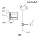
好ましくは、前記ガス密度リレー(又はガス密度監視装置)は、マイクロウォーターセンサをさらに含み、前記マイクロウォーターセンサはそれぞれ前記ガス密度リレー本体と前記知能制御ユニットに接続される。 Preferably, the gas density relay (or gas density monitoring device) further includes a micro water sensor, which is connected to the gas density relay body and the intelligent control unit, respectively.
より好ましくは、前記ガス密度リレー(又はガス密度監視装置)は、ガス循環機構をさらに含み、前記ガス循環機構はそれぞれ前記ガス密度リレー本体と前記知能制御ユニットに接続され、前記ガス循環機構は毛細管、密閉チャンバー及び加熱素子を含む。 More preferably, the gas density relay (or gas density monitor) further includes a gas circulation mechanism, which is connected to the gas density relay body and the intelligent control unit, respectively, and which includes a capillary tube, a sealed chamber, and a heating element.
さらに、前記マイクロウォーターセンサは、前記ガス循環機構の密閉チャンバー、毛細管中、毛細管口、毛細管外に取り付けられてもよい。 Furthermore, the micro water sensor may be attached to a sealed chamber of the gas circulation mechanism, inside a capillary, at a capillary mouth, or outside a capillary.
好ましくは、前記ガス密度リレー(又はガス密度監視装置)は、分解物センサを更に含み、前記分解物センサは、それぞれ前記ガス密度リレー本体と前記知能制御ユニットとに接続される。 Preferably, the gas density relay (or gas density monitor) further includes a decomposition product sensor, which is connected to the gas density relay body and the intelligent control unit, respectively.
好ましくは、前記ガス密度リレー(又はガス密度監視装置)は、監視するためのカメラを更に含む。 Preferably, the gas density relay (or gas density monitor) further includes a camera for monitoring.
上記内容において、前記オンラインセルフチェック機能を有するガス密度リレーは、一般的にその構成要素が一体構造に設計されることを指し、ガス密度監視装置は一般的にその構成要素が別体構造に設計され、柔軟に構成されることを指す。 In the above, a gas density relay with an online self-check function generally refers to components that are designed as an integrated structure, while a gas density monitor generally refers to components that are designed as separate structures and are flexibly configured.
本願の第2態様はガス密度リレーのチェック方法を提供し、
正常動作状態の場合に、ガス密度リレー(又はガス密度監視装置)は電気機器内のガス密度値を監視することと、
ガス密度リレー(又はガス密度監視装置)は設定されたチェック時間及び/又はチェック指令、及びガス密度値状況及び/又は温度値状況に基づいて、ガス密度リレーを許可し及び/又はチェックできる状況で、
知能制御ユニットの温度調節機構への制御により、ガス密度リレーの温度を上昇させ、さらにガス密度リレー本体の温度補償素子の温度が上昇し、ガス密度リレー本体に接点動作を発生させ、接点動作はオンラインチェック接点信号サンプリングユニットを介して知能制御ユニットに伝達され、知能制御ユニットは接点動作時の圧力値、温度値に基づいてガス密度値を取得し、又はガス密度値を直接取得し、ガス密度リレー本体の接点信号動作値を検出し、ガス密度リレーの接点信号動作値のチェック作業を完了することと、
全ての接点信号チェック作業が完了した後、知能制御ユニットは温度調節機構の加熱素子をオフにすることと、を含む。
A second aspect of the present application provides a method for checking a gas density relay, comprising:
Under normal operating conditions, the gas density relay (or the gas density monitor) monitors a gas density value within the electrical equipment;
The gas density relay (or the gas density monitor) can enable and/or check the gas density relay based on the set check time and/or check command, and the gas density value status and/or the temperature value status.
The intelligent control unit controls the temperature regulating mechanism to increase the temperature of the gas density relay, and further increases the temperature of the temperature compensation element of the gas density relay body, causing the gas density relay body to operate contacts. The contact operation is transmitted to the intelligent control unit through the online check contact signal sampling unit, and the intelligent control unit obtains the gas density value according to the pressure value and temperature value at the time of contact operation, or directly obtains the gas density value, detects the contact signal operation value of the gas density relay body, and completes the checking work of the contact signal operation value of the gas density relay.
After all the contact signal checking operations are completed, the intelligent control unit turns off the heating element of the temperature adjustment mechanism.
好ましくは、ガス密度リレーのチェック方法であって、
正常動作状態の場合に、ガス密度リレー(又はガス密度監視装置)は電気機器内のガス密度値を監視すると同時に、ガス密度リレー(又はガス密度監視装置)はガス密度検出センサ及び知能制御ユニットにより電気機器内のガス密度値をオンラインで監視することと、
ガス密度リレー(又はガス密度監視装置)は設定されたチェック時間及び/又はチェック指令、及びガス密度値状況及び/又は温度値状況に基づいて、ガス密度リレーを許可し及び/又はチェックできる状況で、
知能制御ユニットによりオンラインチェック接点信号サンプリングユニットをチェック状態に調整し、チェック状態で、オンラインチェック接点信号サンプリングユニットは、ガス密度リレー本体の接点信号の制御回路を切断し、ガス密度リレー本体の接点を知能制御ユニットに接続することと、
知能制御ユニットの温度調節機構への制御により、ガス密度リレーの温度を上昇させ、さらにガス密度リレー本体の温度補償素子の温度が上昇し、ガス密度リレー本体に接点動作を発生させ、接点動作はオンラインチェック接点信号サンプリングユニットを介して知能制御ユニットに伝達され、知能制御ユニットは接点動作時の圧力値、温度値に基づいてガス密度値を取得し、又はガス密度値を直接取得し、ガス密度リレー本体の接点信号動作値を検出し、ガス密度リレーの接点信号動作値のチェック作業を完了することと、
知能制御ユニットの温度調節機構への制御により、ガス密度リレーの温度を低下させ、さらにガス密度リレー本体の温度補償素子の温度が低下することにより、ガス密度リレー本体に接点リセットが発生し、接点リセットはオンラインチェック接点信号サンプリングユニットを介して知能制御ユニットに伝達され、知能制御ユニットは接点リセット時の圧力値、温度値に基づいてガス密度値を取得し、又はガス密度値を直接取得し、ガス密度リレー本体の接点信号の戻り値を検出し、ガス密度リレーの接点信号戻り値のチェック作業を完了することと、
全ての接点信号チェック作業が完了した後、知能制御ユニットは温度調節機構の加熱素子をオフにするとともに、オンラインチェック接点信号サンプリングユニットを動作状態に調整し、ガス密度リレー本体の接点信号の制御回路は正常動作状態に復帰して稼働することと、を含む。
Preferably, the method for checking a gas density relay comprises the steps of:
Under normal operation, the gas density relay (or the gas density monitoring device) monitors the gas density value in the electrical equipment, and at the same time, the gas density relay (or the gas density monitoring device) monitors the gas density value in the electrical equipment online through the gas density detection sensor and the intelligent control unit;
The gas density relay (or the gas density monitor) can enable and/or check the gas density relay based on the set check time and/or check command, and the gas density value status and/or the temperature value status.
The intelligent control unit adjusts the online check contact signal sampling unit to a check state, and in the check state, the online check contact signal sampling unit cuts off the control circuit of the contact signal of the gas density relay body, and connects the contact of the gas density relay body to the intelligent control unit;
The intelligent control unit controls the temperature regulating mechanism to increase the temperature of the gas density relay, and further increases the temperature of the temperature compensation element of the gas density relay body, causing the gas density relay body to operate contacts. The contact operation is transmitted to the intelligent control unit through the online check contact signal sampling unit, and the intelligent control unit obtains the gas density value according to the pressure value and temperature value at the time of contact operation, or directly obtains the gas density value, detects the contact signal operation value of the gas density relay body, and completes the checking work of the contact signal operation value of the gas density relay.
The intelligent control unit controls the temperature regulating mechanism to reduce the temperature of the gas density relay, and the temperature of the temperature compensation element of the gas density relay body is reduced, causing a contact reset in the gas density relay body. The contact reset is transmitted to the intelligent control unit through the online check contact signal sampling unit, and the intelligent control unit obtains the gas density value according to the pressure value and temperature value at the time of contact reset, or directly obtains the gas density value, detects the contact signal return value of the gas density relay body, and completes the check work of the contact signal return value of the gas density relay.
After all the contact signal checking operations are completed, the intelligent control unit turns off the heating element of the temperature regulating mechanism, adjusts the online check contact signal sampling unit to an operating state, and the contact signal control circuit of the gas density relay body returns to a normal operating state and operates.
好ましくは、前記ガス密度リレー(又はガス密度監視装置)は弁及び圧力調節機構を更に含み、前記圧力調節機構のガス路はガス密度リレー本体のガス路に連通し、前記弁の一端には電気機器に連通する接続ポートが設けられ、弁の他端はガス密度リレー本体のガス路に連通し、前記チェック方法は、
正常動作状態の場合に、ガス密度リレー(又はガス密度監視装置)は電気機器内のガス密度値を監視することと、
ガス密度リレー(又はガス密度監視装置)は設定されたチェック時間及び/又はチェック指令、及びガス密度値状況及び/又は温度値状況に基づいて、ガス密度リレーを許可し及び/又はチェックできる状況で、
知能制御ユニットにより弁を閉じることと、
知能制御ユニットにより圧力調節機構を駆動し、ガス圧力を徐々に低下させ、かつ知能制御ユニットにより温度調節機構を制御し、ガス密度リレーの温度を上昇させ、さらにガス密度リレー本体の温度補償素子の温度が上昇し、ガス密度リレー本体に接点動作を発生させ、接点動作はオンラインチェック接点信号サンプリングユニットを介して知能制御ユニットに伝達され、知能制御ユニットは接点動作時の圧力値、温度値に基づいてガス密度値を取得し、又はガス密度値を直接取得し、ガス密度リレー本体の接点信号動作値を検出し、ガス密度リレーの接点信号動作値のチェック作業を完了することと、
全ての接点信号チェック作業が完了した後、知能制御ユニットは弁を開き、かつ知能制御ユニットは温度調節機構の加熱素子をオフにすること、をさらに含む。
Preferably, the gas density relay (or gas density monitoring device) further includes a valve and a pressure regulating mechanism, a gas path of the pressure regulating mechanism communicates with a gas path of the gas density relay body, one end of the valve is provided with a connection port communicating with an electric device, and the other end of the valve communicates with the gas path of the gas density relay body, and the checking method includes the steps of:
Under normal operating conditions, the gas density relay (or the gas density monitor) monitors a gas density value within the electrical equipment;
The gas density relay (or the gas density monitor) can enable and/or check the gas density relay based on the set check time and/or check command, and the gas density value status and/or the temperature value status.
closing the valve with an intelligent control unit;
The intelligent control unit drives the pressure regulating mechanism to gradually reduce the gas pressure, and the intelligent control unit controls the temperature regulating mechanism to increase the temperature of the gas density relay, and the temperature of the temperature compensation element of the gas density relay body increases, causing the gas density relay body to operate in contact, and the contact operation is transmitted to the intelligent control unit through the online check contact signal sampling unit, and the intelligent control unit obtains the gas density value according to the pressure value and temperature value at the time of contact operation, or directly obtains the gas density value, detects the contact signal operation value of the gas density relay body, and completes the checking work of the contact signal operation value of the gas density relay;
After all the contact signal checking operations are completed, the intelligent control unit opens the valve, and the intelligent control unit turns off the heating element of the temperature regulating mechanism.
好ましくは、前記ガス密度リレー(又はガス密度監視装置)は弁及び圧力調節機構を更に含み、前記圧力調節機構のガス路はガス密度リレー本体のガス路に連通し、前記弁の一端には電気機器に連通する接続ポートが設けられ、弁の他端はガス密度リレー本体のガス路に連通し、前記チェック方法は、
正常動作状態の場合に、ガス密度リレー(又はガス密度監視装置)は電気機器内のガス密度値を監視すると同時に、ガス密度リレー(又はガス密度監視装置)はガス密度検出センサ及び知能制御ユニットにより電気機器内のガス密度値をオンラインで監視することと、
ガス密度リレー(又はガス密度監視装置)は設定されたチェック時間及び/又はチェック指令、及びガス密度値状況及び/又は温度値状況に基づいて、ガス密度リレーを許可し及び/又はチェックできる状況で、
知能制御ユニットにより弁を閉じることと、
知能制御ユニットによりオンラインチェック接点信号サンプリングユニットをチェック状態に調整し、チェック状態で、オンラインチェック接点信号サンプリングユニットは、ガス密度リレー本体の接点信号の制御回路を切断し、ガス密度リレー本体の接点を知能制御ユニットに接続することと、
知能制御ユニットの温度調節機構への制御により、ガス密度リレーの温度を上昇させ、さらにガス密度リレー本体の温度補償素子の温度が上昇し、かつ知能制御ユニットにより圧力調節機構を駆動することにより、ガス圧力を徐々に低下させ、ガス密度リレー本体に接点動作を発生させ、接点動作はオンラインチェック接点信号サンプリングユニットを介して知能制御ユニットに伝達され、知能制御ユニットは接点動作時の圧力値、温度値に基づいてガス密度値を取得し、又はガス密度値を直接取得し、ガス密度リレー本体の接点信号動作値を検出し、ガス密度リレーの接点信号動作値のチェック作業を完了することと、
知能制御ユニットの温度調節機構への制御により、ガス密度リレーの温度を低下させ、さらにガス密度リレー本体の温度補償素子の温度が低下し、かつ知能制御ユニットにより圧力調節機構を駆動することにより、ガス圧力を徐々に上昇させ、ガス密度リレー本体に接点リセットを発生させ、接点リセットはオンラインチェック接点信号サンプリングユニットを介して知能制御ユニットに伝達され、知能制御ユニットは接点リセット時の圧力値、温度値に基づいてガス密度値を取得し、又はガス密度値を直接取得し、ガス密度リレー本体の接点信号戻り値を検出し、ガス密度リレーの接点信号戻り値のチェック作業を完了することと、
全ての接点信号チェック作業が完了した後、知能制御ユニットは弁を開き、かつ知能制御ユニットは温度調節機構の加熱素子をオフにするとともに、オンラインチェック接点信号サンプリングユニットを動作状態に調整し、ガス密度リレー本体の接点信号の制御回路は正常動作状態に復帰して稼働することと、を更に含む。
Preferably, the gas density relay (or gas density monitoring device) further includes a valve and a pressure regulating mechanism, a gas path of the pressure regulating mechanism communicates with a gas path of the gas density relay body, one end of the valve is provided with a connection port communicating with an electric device, and the other end of the valve communicates with the gas path of the gas density relay body, and the checking method includes the steps of:
Under normal operation, the gas density relay (or the gas density monitoring device) monitors the gas density value in the electrical equipment, and at the same time, the gas density relay (or the gas density monitoring device) monitors the gas density value in the electrical equipment online through the gas density detection sensor and the intelligent control unit;
The gas density relay (or the gas density monitor) can enable and/or check the gas density relay based on the set check time and/or check command, and the gas density value status and/or the temperature value status.
closing the valve with an intelligent control unit;
The intelligent control unit adjusts the online check contact signal sampling unit to a check state, and in the check state, the online check contact signal sampling unit cuts off the control circuit of the contact signal of the gas density relay body, and connects the contact of the gas density relay body to the intelligent control unit;
The intelligent control unit controls the temperature regulating mechanism to increase the temperature of the gas density relay, and then the temperature of the temperature compensation element of the gas density relay body increases, and the intelligent control unit drives the pressure regulating mechanism to gradually reduce the gas pressure, causing the gas density relay body to operate in contact, and the contact operation is transmitted to the intelligent control unit through the online check contact signal sampling unit, and the intelligent control unit obtains the gas density value according to the pressure value and temperature value at the time of contact operation, or directly obtains the gas density value, detects the contact signal operation value of the gas density relay body, and completes the checking work of the contact signal operation value of the gas density relay;
The intelligent control unit controls the temperature regulating mechanism to reduce the temperature of the gas density relay, and the temperature of the temperature compensation element of the gas density relay body is reduced. The intelligent control unit drives the pressure regulating mechanism to gradually increase the gas pressure, causing a contact reset in the gas density relay body. The contact reset is transmitted to the intelligent control unit through the online check contact signal sampling unit, and the intelligent control unit obtains the gas density value according to the pressure value and temperature value at the time of contact reset, or directly obtains the gas density value, detects the contact signal return value of the gas density relay body, and completes the check work of the contact signal return value of the gas density relay.
After all the contact signal checking operations are completed, the intelligent control unit opens the valve, and the intelligent control unit turns off the heating element of the temperature regulating mechanism, and adjusts the online check contact signal sampling unit to an operating state, and the contact signal control circuit of the gas density relay body returns to a normal operating state and operates.
好ましくは、前記ガス密度リレー(又はガス密度監視装置)は加熱デバイス及び弁を更に含み、前記加熱デバイスは前記知能制御ユニットに接続され、前記弁の一端には電気機器に連通する接続ポートが設けられ、前記弁の他端はガス密度リレー本体のガス路に連通し、前記チェック方法は、
正常動作状態の場合に、ガス密度リレー(又はガス密度監視装置)は電気機器内のガス密度値を監視すると同時に、ガス密度リレー(又はガス密度監視装置)はガス密度検出センサ及び知能制御ユニットにより電気機器内のガス密度値をオンラインで監視することと、
ガス密度リレー(又はガス密度監視装置)は設定されたチェック時間及び/又はチェック指令、及びガス密度値状況及び/又は温度値状況に基づいて、ガス密度リレーを許可し及び/又はチェックできる状況で、
知能制御ユニットにより接点信号サンプリングユニットをチェック状態に調整し、チェック状態で、接点信号サンプリングユニットはガス密度リレー本体の接点信号の制御回路を切断し、ガス密度リレー本体の接点を知能制御ユニットに接続することと、
知能制御ユニットにより前記加熱デバイスの加熱を制御し、ガス密度リレー本体のガスの温度変化をもたらし、設定値に達した後、知能制御ユニットにより弁を閉じ、さらに知能制御ユニットにより前記加熱デバイスをオフにすることと、
ガスの温度又は圧力が適切値まで低下した後、さらに知能制御ユニットの温度調節機構への制御により、ガス密度リレーの温度を上昇させ、さらにガス密度リレー本体の温度補償素子の温度が上昇し、ガス密度リレー本体に接点動作を発生させ、接点動作は接点信号サンプリングユニットを介して知能制御ユニットに伝達され、知能制御ユニットは接点動作時の圧力値、温度値に基づいてガス密度値を取得し、又はガス密度値を直接取得し、ガス密度リレー本体の接点信号動作値を検出し、ガス密度リレーの接点信号動作値のチェック作業を完了することと、
全ての接点信号チェック作業が完了した後、知能制御ユニットは弁を開き、かつ知能制御ユニットは温度調節機構をオフにすることと、を更に含む。
Preferably, the gas density relay (or gas density monitor) further includes a heating device and a valve, the heating device is connected to the intelligent control unit, one end of the valve is provided with a connection port communicating with an electrical device, and the other end of the valve is connected to a gas path of the gas density relay body, and the checking method includes:
Under normal operation, the gas density relay (or the gas density monitoring device) monitors the gas density value in the electrical equipment, and at the same time, the gas density relay (or the gas density monitoring device) monitors the gas density value in the electrical equipment online through the gas density detection sensor and the intelligent control unit;
The gas density relay (or the gas density monitor) can enable and/or check the gas density relay based on the set check time and/or check command, and the gas density value status and/or the temperature value status.
The intelligent control unit adjusts the contact signal sampling unit to a check state, and in the check state, the contact signal sampling unit cuts off the control circuit of the contact signal of the gas density relay body, and connects the contact of the gas density relay body to the intelligent control unit;
Control the heating of the heating device by the intelligent control unit, so as to cause the temperature change of the gas in the gas density relay body, and after reaching a set value, close the valve by the intelligent control unit, and then turn off the heating device by the intelligent control unit;
After the gas temperature or pressure is reduced to an appropriate value, the intelligent control unit controls the temperature regulating mechanism to further increase the temperature of the gas density relay, and the temperature of the temperature compensation element of the gas density relay body is further increased, causing the gas density relay body to make a contact operation, and the contact operation is transmitted to the intelligent control unit through the contact signal sampling unit, and the intelligent control unit obtains the gas density value according to the pressure value and temperature value at the time of contact operation, or directly obtains the gas density value, detects the contact signal operation value of the gas density relay body, and completes the checking work of the contact signal operation value of the gas density relay;
After all the contact signal checking operations are completed, the intelligent control unit opens the valve, and the intelligent control unit turns off the temperature adjustment mechanism.
好ましくは、前記接点信号は警報、及び/又は閉鎖を含む。 Preferably, the contact signal includes an alarm and/or a closure.
好ましくは、前記ガス密度検出センサは、少なくとも1つの圧力センサ及び少なくとも1つの温度センサを含み、或いは、前記ガス密度検出センサは圧力センサ及び温度センサで構成されたガス密度トランスミッターであり、或いは、前記ガス密度検出センサはクォーツ音叉テクノロジーを採用する密度検出センサである。 Preferably, the gas density detection sensor includes at least one pressure sensor and at least one temperature sensor, or the gas density detection sensor is a gas density transmitter composed of a pressure sensor and a temperature sensor, or the gas density detection sensor is a density detection sensor employing quartz tuning fork technology.
好ましくは、前記ガス密度リレー(又はガス密度監視装置)はチェックを完了した後、異常があれば、警報を自動的に発するとともに、遠位端にアップロードし、又は指定された受信機に送信することができる。 Preferably, after completing the check, the gas density relay (or gas density monitor) can automatically issue an alarm if there is an abnormality and upload it to the remote end or transmit it to a designated receiver.
好ましくは、前記チェック方法は、現場でガス密度値及びチェック結果を表示し、又はバックグラウンドでガス密度値及びチェック結果を表示することを更に含む。 Preferably, the checking method further includes displaying the gas density value and the check result on-site or displaying the gas density value and the check result in the background.
好ましくは、前記チェック方法は、前記知能制御ユニットの制御が現場、及び/又はバックグラウンドにより制御されることを更に含む。 Preferably, the checking method further includes controlling the intelligent control unit locally and/or in the background.
本願の第3態様はガス密度リレーの改造方法を提供し、
ガス密度検出センサを、ガス密度リレー本体に連通することと、
前記ガス密度検出センサのガス路を、多方継手の第1インタフェースに接続することと、
温度調節機構をガス密度リレー本体のケース内又はケース外に設け、前記温度調節機構は前記ガス密度リレー本体の温度補償素子の温度昇降を調節し、前記ガス密度リレー本体に接点信号動作を発生させることと、
オンラインチェック接点信号サンプリングユニットを、前記ガス密度リレー本体に直接的又は間接的に接続し、前記オンラインチェック接点信号サンプリングユニットは、前記ガス密度リレー本体の接点が動作する時に生成される接点信号をサンプリングすることと、
知能制御ユニットを、それぞれ前記ガス密度検出センサ、前記温度調節機構及び前記オンラインチェック接点信号サンプリングユニットに接続し、前記温度調節機構の制御、圧力値収集及び温度値収集、及び/又はガス密度値収集、並びに前記ガス密度リレー本体の接点信号動作値及び/又は接点信号戻り値の検出を完了することと、を更に含み、
ここで、前記接点信号は警報、及び/又は閉鎖を含む。
A third aspect of the present application provides a method for retrofitting a gas density relay, comprising:
A gas density detection sensor is connected to a gas density relay body;
Connecting a gas path of the gas density detection sensor to a first interface of a multi-way joint;
a temperature control mechanism is provided inside or outside the case of the gas density relay body, and the temperature control mechanism controls the temperature rise and fall of the temperature compensation element of the gas density relay body to generate a contact signal operation in the gas density relay body;
An online check contact signal sampling unit is directly or indirectly connected to the gas density relay body, and the online check contact signal sampling unit samples a contact signal generated when a contact of the gas density relay body operates;
Further comprising: connecting an intelligent control unit to the gas density detection sensor, the temperature adjustment mechanism and the online check contact signal sampling unit respectively, and completing the control of the temperature adjustment mechanism, the pressure value collection and temperature value collection, and/or the gas density value collection, and the detection of the contact signal operating value and/or contact signal return value of the gas density relay body;
Here, the contact signal includes an alarm and/or a closure.
好ましくは、前記ガス密度検出センサ、前記オンラインチェック接点信号サンプリングユニット及び前記知能制御ユニットは前記ガス密度リレー本体に設けられ、或いは、
前記温度調節機構は前記ガス密度リレー本体に設けられ、或いは、
前記温度調節機構は前記ガス密度リレー本体内に設けられ、或いは、
前記ガス密度検出センサ、前記温度調節機構、前記オンラインチェック接点信号サンプリングユニット及び前記知能制御ユニットは前記ガス密度リレー本体に設けられ、或いは、
前記多方継手は前記ガス密度リレー本体に設けられ、或いは、
前記温度調節機構は前記多方継手に固定され、或いは、
前記温度調節機構、前記ガス密度検出センサは前記多方継手に設けられ、或いは、
前記オンラインチェック接点信号サンプリングユニット及び前記知能制御ユニットは前記多方継手に設けられる。
Preferably, the gas density detection sensor, the online check contact signal sampling unit and the intelligent control unit are installed in the gas density relay body; or
The temperature adjustment mechanism is provided in the gas density relay body, or
The temperature adjustment mechanism is provided within the gas density relay body, or
The gas density detection sensor, the temperature control mechanism, the online check contact signal sampling unit and the intelligent control unit are installed in the gas density relay body; or
The multi-way joint is provided on the gas density relay body, or
The temperature adjustment mechanism is fixed to the multi-way joint; or
The temperature adjustment mechanism and the gas density detection sensor are provided in the multi-way joint, or
The online check contact signal sampling unit and the intelligent control unit are installed in the multi-way joint.
好ましくは、前記ガス密度リレーの改造方法は、弁の一端を電気機器に連通し、前記弁の他端を前記ガス密度リレー本体のガス路に連通することを更に含む。 Preferably, the method for modifying the gas density relay further includes connecting one end of the valve to an electrical device and connecting the other end of the valve to a gas path of the gas density relay body.
より好ましくは、前記弁を前記知能制御ユニットにも接続することにより、前記弁が前記知能制御ユニットの制御で閉じ又は開くことを実現する。 More preferably, the valve is also connected to the intelligent control unit, thereby enabling the valve to be closed or opened under the control of the intelligent control unit.
より好ましくは、前記ガス密度リレーの改造方法は、自己密封弁を前記多方継手と前記弁との間に取り付け、或いは、前記弁を前記多方継手と自己密封弁との間に取り付けることを更に含む。 More preferably, the method for modifying the gas density relay further includes installing a self-sealing valve between the multi-way fitting and the valve, or installing the valve between the multi-way fitting and the self-sealing valve.
好ましくは、前記ガス密度リレーの改造方法は、圧力調節機構であって、前記圧力調節機構のガス路を、前記ガス密度リレー本体に連通し、前記圧力調節機構は前記ガス密度リレー本体の圧力昇降を調整し、さらに温度調節機構と嵌合及び/又は結合することにより、前記ガス密度リレー本体に接点信号動作を発生させるように配置され、前記圧力調節機構を前記知能制御ユニットにも接続することにより、前記圧力調節機構が前記知能制御ユニットの制御で動作することを更に含み、或いは、
加熱デバイスであって、前記知能制御ユニットを前記加熱デバイスに接続することを更に含み、或いは、
エアチャンバー及び加熱デバイスであって、前記エアチャンバーを前記ガス密度リレー本体に連通し、前記エアチャンバーの外部又は内部に前記加熱デバイスが設けられ、前記知能制御ユニットを前記加熱デバイスに接続することを更に含む。
Preferably, the method for modifying the gas density relay further includes a pressure regulating mechanism, the gas path of the pressure regulating mechanism being connected to the gas density relay body, the pressure regulating mechanism being arranged to adjust the pressure rise and fall of the gas density relay body, and further being fitted and/or coupled with a temperature regulating mechanism to generate a contact signal operation in the gas density relay body, and the pressure regulating mechanism is also connected to the intelligent control unit, so that the pressure regulating mechanism operates under the control of the intelligent control unit; or
A heating device, further comprising connecting the intelligent control unit to the heating device, or
The present invention further includes an air chamber and a heating device, the air chamber being connected to the gas density relay body, the heating device being disposed outside or inside the air chamber, and the intelligent control unit being connected to the heating device.
より好ましくは、前記ガス密度リレーの改造方法は、前記圧力調節機構にガス補充ポートを設け、或いは、ガス密度リレーにより監視された電気機器にガス補充ポートを設け、或いは、前記多方継手にガス補充ポートを設け、或いは、前記ガス密度リレー本体にガス補充ポートを設けることを更に含む。 More preferably, the method for modifying the gas density relay further includes providing a gas refill port in the pressure adjustment mechanism, or providing a gas refill port in an electrical device monitored by the gas density relay, or providing a gas refill port in the multi-way joint, or providing a gas refill port in the gas density relay body.
従来技術に比べて、本発明の技術的解決手段は以下の有益な効果を有する。 Compared with the prior art, the technical solution of the present invention has the following beneficial effects:
本願は、オンラインセルフチェック機能を有するガス密度リレー及びそのチェック方法を提供し、高圧、中圧電気機器に用いられ、ガス密度リレー本体、ガス密度検出センサ、温度調節機構、オンラインチェック接点信号サンプリングユニット及び知能制御ユニットを含む。温度調節機構により密度リレーの温度補償素子の温度昇降を調節することにより、ガス密度リレー本体に接点動作を発生させ、接点動作はオンラインチェック接点信号サンプリングユニットを介して知能制御ユニットに伝達され、知能制御ユニットは接点動作時の密度値に基づいて、ガス密度リレー本体の警報及び/又は閉鎖接点信号動作値及び/又は戻り値を検出し、密度リレーチェック継手を増設する必要がなく、点検員が現場に出ること必要がなくガス密度リレーのチェック作業を完了することができ、電網の信頼性を向上させ、作業効率を向上させ、コストを低減する。同時に、知能制御ユニットによりガス密度リレー本体とガス密度検出センサとの間の相互セルフチェックを行い、オンラインセルフチェック機能を有するガス密度リレーのメンテナンスフリーを実現することができる。 The present application provides a gas density relay with an online self-check function and a check method thereof, which is used in high-voltage and medium-voltage electrical equipment, and includes a gas density relay body, a gas density detection sensor, a temperature adjustment mechanism, an online check contact signal sampling unit, and an intelligent control unit. The temperature adjustment mechanism adjusts the temperature rise and fall of the temperature compensation element of the density relay to generate a contact operation in the gas density relay body, and the contact operation is transmitted to the intelligent control unit via the online check contact signal sampling unit. The intelligent control unit detects the alarm and/or close contact signal operation value and/or return value of the gas density relay body based on the density value at the time of contact operation, and the check work of the gas density relay can be completed without the need to add a density relay check joint or send an inspector to the site, thereby improving the reliability of the power grid, improving work efficiency, and reducing costs. At the same time, the intelligent control unit performs mutual self-check between the gas density relay body and the gas density detection sensor, thereby realizing a maintenance-free gas density relay with an online self-check function.
本願を構成する一部の図面は本願のさらなる理解を提供するために用いられ、本願の例示的な実施例及びその説明は本願を説明するために用いられ、本願を不当に限定するものではない。 Some of the drawings constituting this application are used to provide further understanding of this application, and the exemplary embodiments and their descriptions are used to explain this application and are not intended to unduly limit this application.
本発明の目的、技術的解決手段及び効果をより明瞭で明確にするために、以下に図面を参照しながら実例を挙げて本発明をさらに詳細に説明する。理解されるように、ここで説明される具体的な実施例は本発明を説明するために用いられ、本発明を限定するものではない。 In order to make the objectives, technical solutions and effects of the present invention clearer and more precise, the present invention will be described in more detail below by way of examples with reference to the drawings. It should be understood that the specific embodiments described herein are used to illustrate the present invention, and are not intended to limit the present invention.
実施例1:
図1は本願の実施例1の高中圧電気機器用のオンラインチェック機能を有するガス密度リレーの構造概略図である。図1に示すように、オンラインチェック機能を有するガス密度リレーはガス密度リレー本体1を含み、ガス密度リレー本体1は、ケース101、及びケース101内に設けられたベース102、端座108、圧力検出器103、温度補償素子104、いくつかの信号発生器109、ムーブメント105、指針106、ダイヤル107を含む。圧力検出器103の一端はベース102に固定され連通し、圧力検出器103の他端は端座108により温度補償素子104の一端に接続され、前記温度補償素子104の他端に横梁が設けられ、前記横梁に前記信号発生器109を駆動し、前記信号発生器109の接点をオン・オフにする調節材が設けられる。前記ムーブメント105は前記ベース102に固定され、前記温度補償素子104の他端はリンクにより前記ムーブメント105に接続され、又は前記ムーブメント105に直接接続され、前記指針106は前記ムーブメント105の芯に取り付けられ前記ダイヤル107の前に設けられ、前記指針106は前記ダイヤル107と合わせてガス密度値を表示する。前記ガス密度リレー本体1は表示値表示を有するデジタルデバイス又は液晶デバイスを更に含んでもよい。
Example 1:
Fig. 1 is a structural schematic diagram of a gas density relay with online check function for high and medium voltage electrical equipment according to a first embodiment of the present invention. As shown in Fig. 1, the gas density relay with online check function includes a gas
また、前記ガス密度リレーは、圧力センサ2、温度センサ3、温度調節機構5、オンラインチェック接点信号サンプリングユニット6、知能制御ユニット7をさらに含む。前記圧力センサ2はガス路で圧力検出器103に連通し、前記温度調節機構5はケース101内(又はケース101)に設けられ、オンラインチェック接点信号サンプリングユニット6はそれぞれ信号発生器109と知能制御ユニット7とに接続され、前記温度センサ3はケース101内に設けられ、前記圧力センサ2、前記温度センサ3、前記温度調節機構5はそれぞれ知能制御ユニット7に接続される。前記温度調節機構5は主に加熱素子501、温度調節機構ハウジング503で構成される。
The gas density relay further includes a
ここで、前記信号発生器109は、マイクロスイッチ又は磁気アシスト式電気接点を含み、ガス密度リレー本体1は前記信号発生器109を介して接点信号を出力し、前記圧力検出器103はバーデン管又は波形管を含み、前記温度補償素子104は温度補償シート又はケース内に封止されたガスを採用する。本願のガス密度リレーは、オイル充填タイプの密度リレー、オイルレスタイプの密度リレー、ガス密度計、ガス密度スイッチ又はガス圧力計を含んでもよい。
Here, the
本実施例のガス密度リレーにおいて、圧力検出器103に基づいて温度補償素子104により、変化した圧力及び温度を補正することにより、六フッ化硫黄ガス密度の変化を反映する。即ち、被測定媒体の六フッ化硫黄(SF6)ガスの圧力作用で、温度補償素子104の作用を有するため、六フッ化硫黄ガスの密度値が変化する時、六フッ化硫黄ガスの圧力値も対応して変化し、圧力検出器103の末端に対応する弾性変形変位を強制的に発生させ、温度補償素子104を介して、ムーブメント105に伝達し、ムーブメント105はまた指針106に伝達し、それにより被測定の六フッ化硫黄ガスの密度値をダイヤル107に指示する。信号発生器109は出力警報閉鎖接点とする。このようにガス密度リレー本体1は六フッ化硫黄ガスの密度値を表示することができる。ガス漏れが発生し、六フッ化硫黄ガスの密度値が低下すれば、圧力検出器103は対応する下向き変位を生成し、温度補償素子104を介してムーブメント105に伝達し、ムーブメント105はまた指針106に伝達し、指針106は表示値が小さい方向に移動し、ダイヤル107にガス漏れ程度を具体的に表示する同時に、圧力検出器103は温度補償素子104により横梁が下向きに変位するように連動させ、横梁における調節材は信号発生器109から徐々に離れ、一定の程度になると、信号発生器109の接点がオンになり、対応する接点信号(警報又は閉鎖)を送信し、電気スイッチ等の機器における六フッ化硫黄ガスの密度を監視し制御することを達成し、電気機器を安全に動作させる。
In the gas density relay of this embodiment, the
ガス密度値が上昇すると、即ち密封エアチャンバー内の六フッ化硫黄ガス圧力値が設定された六フッ化硫黄ガス圧力値より大きい場合、圧力値も対応に上昇し、圧力検出器103の末端と温度補償素子104は対応する上向き変位を生成し、温度補償素子104によって横梁も上向きに変位し、横梁における調節材は上向きに変位し信号発生器109の接点をオフにするように駆動し、接点信号(警報又は閉鎖)が解除される。
When the gas density value rises, i.e. when the sulfur hexafluoride gas pressure value in the sealed air chamber is greater than the set sulfur hexafluoride gas pressure value, the pressure value also rises correspondingly, the end of the
前記温度調節機構5は加熱素子であり、或いは、前記温度調節機構は主に加熱素子、保温材、温度コントローラー、温度検出器、温度調節機構ハウジング等で構成され、或いは、前記温度調節機構は主に加熱素子及び温度コントローラーで構成され、或いは、前記温度調節機構は主に加熱素子、加熱電力レギュレーター及び温度コントローラーで構成され、或いは、前記温度調節機構は主に加熱素子、冷却素子、加熱電力レギュレーター及び温度コントローラーで構成され、或いは、前記温度調節機構は主に加熱素子、加熱電力レギュレーター及び恒温コントローラーで構成され、或いは、前記温度調節機構は主に加熱素子、温度コントローラー、温度検出器等で構成され、或いは、前記温度調節機構は加熱素子であり、前記加熱素子は温度補償素子の近傍に設けられ、或いは、前記温度調節機構はマイクロ恒温ボックスであり、ここで、前記加熱素子はシリコーンゴム加熱器、抵抗線、電熱ベルト、電熱棒、熱ファン、赤外線加熱素子、半導体のうちの一種を含むが、これらに限定されなく、前記温度コントローラーはPIDコントローラー、PIDとファジー制御を組み合わせたコントローラー、周波数変換コントローラー、PLCコントローラーのうちの一種を含むが、これらに限定されない。 The temperature adjustment mechanism 5 is a heating element, or the temperature adjustment mechanism is mainly composed of a heating element, a heat retaining material, a temperature controller, a temperature detector, a temperature adjustment mechanism housing, etc., or the temperature adjustment mechanism is mainly composed of a heating element and a temperature controller, or the temperature adjustment mechanism is mainly composed of a heating element, a heating power regulator, and a temperature controller, or the temperature adjustment mechanism is mainly composed of a heating element, a cooling element, a heating power regulator, and a temperature controller, or the temperature adjustment mechanism is mainly composed of a heating element, a heating power regulator, and a constant temperature controller, or the temperature adjustment mechanism is mainly composed of a heating element, a temperature controller, a temperature detector, etc., or the temperature adjustment mechanism is a heating element, and the heating element is disposed near a temperature compensation element, or the temperature adjustment mechanism is a micro constant temperature box, where the heating element includes, but is not limited to, a silicone rubber heater, a resistance wire, an electric heating belt, an electric heating rod, a thermal fan, an infrared heating element, and a semiconductor, and the temperature controller includes, but is not limited to, a PID controller, a controller combining PID and fuzzy control, a frequency conversion controller, and a PLC controller.
圧力センサ2のタイプとしては、絶対圧力センサ、相対圧力センサ、又は絶対圧力センサ及び相対圧力センサであってもよく、数は複数であってもよい。圧力センサの形式としては、拡散シリコン圧力センサ、MEMS圧力センサ、チップ式圧力センサ、コイル誘導圧力センサ(例えばバーデン管に誘導コイルが付いた圧力測定センサ)、抵抗圧力センサ(例えばバーデン管に滑り線抵抗が付いた圧力測定センサ)であってもよく、アナログ量圧力センサであってもよく、デジタル量圧力センサであってもよい。圧力収集は圧力センサ、圧力トランスミッターなどの様々な感圧素子であり、例えば拡散シリコン式、サファイア式、圧電式、歪みゲージ式(抵抗歪みゲージ式、セラミック歪みゲージ式)である。
The type of
温度センサ3は熱電対、サーミスタ、光ファイバ、半導体式であってもよく、接触式及び非接触式であってもよく、熱抵抗及び熱電対であってもよく、デジタル式及びアナログ式であってもよく、例えばDS18B20、pt100である。要するに、温度収集は温度センサ、温度トランスミッターなどの様々な温度感知素子を用いることができる。
The
前記オンラインチェック接点信号サンプリングユニット6は主にガス密度リレー本体1の接点信号サンプリングを完了する。すなわち、オンラインチェック接点信号サンプリングユニット6の基本的な要求又は機能は以下のとおりである。1)チェック時に電気機器の安全稼働に影響を与えず、つまりチェック時に、ガス密度リレー本体1の接点信号が動作する時に、電気機器の安全稼働に影響を与えなく、2)ガス密度リレー本体1の接点信号制御回路はガス密度リレーの性能に影響を与えず、特に知能制御ユニット7の性能に影響を与えず、ガス密度リレーに損傷を与え、又はテスト作業に影響を与えない。
The online check contact
前記知能制御ユニット7の基本的な要求又は機能としては、知能制御ユニット7により温度調節機構5(乃至圧力調節機構11)への制御及び信号収集を完了する。実現:ガス密度リレー本体1の接点信号が動作する時の圧力値及び温度値を検出することができ、対応する20℃時の圧力値P20(密度値)に換算し、即ちガス密度リレー本体1の接点動作値PD20を検出することができ、ガス密度リレー本体1のチェック作業を完了する。或いは、ガス密度リレー本体1の接点信号が動作する時の密度値PD20を直接検出し、ガス密度リレー本体1のチェック作業を完了することができる。同時に、ガス密度リレー本体1の定格圧力値のテストにより、ガス密度リレー本体1、圧力センサ2、温度センサ3の間のセルフチェック作業を完了し、メンテナンスフリーを実現することができる。
The basic requirement or function of the
当然のことながら、知能制御ユニット7は、テストデータ記憶、及び/又はテストデータ導出、及び/又はテストデータ印刷、及び/又はホストコンピューターとのデータ通信、及び/又はアナログ量、デジタル量の情報入力を更に実現することができる。知能制御ユニット7は通信モジュールを含んでもよく、通信モジュールによりテストデータ及び/又はチェック結果等の情報を遠距離で伝送することを実現し、ガス密度リレー本体1の定格圧力値が信号を出力する時、知能制御ユニット7は同時にその時の密度値を収集し、ガス密度リレー本体1の定格圧力値のチェックを完了する。
Of course, the
電気機器は、SF6ガス電気機器、SF6混合ガス電気機器、環境保護型ガス電気機器、又は他の絶縁ガス電気機器を含む。具体的には、電気機器は、GIS、GIL、PASS、遮断器、変流器、計器用変圧器、変圧器、ガス充填キャビネット、リングメインキャビネット等を含む。 The electrical equipment includes SF6 gas electrical equipment, SF6 mixed gas electrical equipment, environmentally friendly gas electrical equipment, or other insulated gas electrical equipment. Specifically, the electrical equipment includes GIS, GIL, PASS, circuit breakers, current transformers, potential transformers, transformers, gas-filled cabinets, ring main cabinets, etc.
ガス密度リレー本体1、圧力センサ2、温度センサ3、温度調節機構5、オンラインチェック接点信号サンプリングユニット6及び知能制御ユニット7の間は必要に応じて柔軟に設置されることができる。例えば、ガス密度リレー本体1、圧力センサ2及び温度センサ3を一体に設けることができ、或いは、ガス密度リレー本体1及び圧力調節機構5を一体に設けることができ、要するに、それらの間の設置は柔軟に配列して組み合わせることができる。
The gas
本実施例のオンラインチェック機能を有するガス密度リレーのチェック及び監視作業作原理は以下のとおりである。 The principle of the check and monitoring operation of the gas density relay with online check function in this embodiment is as follows.
知能制御ユニット7は圧力センサ2、温度センサ3に基づいて電気機器のガス圧力及び温度を監視し、対応する20℃の圧力値P20(即ちガス密度値)を取得する。密度リレー1をチェックする必要がある場合、及び/又はチェックすることができる場合、この時にガス密度値P20≧設定された安全チェック密度値PSであれば、ガス密度リレーは指令を発し、すなわち知能制御ユニット7によりガス密度リレー本体1の制御回路をオフにすることにより、ガス密度リレー本体1をオンラインチェックする場合に電気機器の安全稼働に影響を与えず、チェック時に警報信号を誤って発し、又は制御回路をロックすることもない。ガス密度リレーはチェックを開始する前に、ガス密度値P20≧設定された安全チェック密度値PSの監視及び判断を行ったため、電気機器のガスは安全稼働範囲内にあり、かつガス漏れは緩やかな過程であり、チェック時に安全である。同時に、知能制御ユニット7はガス密度リレー本体1の接点サンプリング回路に連通し、次に、知能制御ユニット7は温度調節機構5に対する操作又は制御により、ガス密度リレーの温度を上昇させ、さらにガス密度リレー本体1の温度補償素子の温度を上昇させ、動作値に近い時に温度変化速度は一秒当たり1.0℃以下であり(乃至一秒当たり0.5℃以下であり、又は必要に応じて該要求を設定する)、すなわち温度要求は安定して上昇し又は下降する。ガス密度リレー本体1に接点動作が発生するまで、接点動作はオンラインチェック接点信号サンプリングユニット6を介して知能制御ユニット7に伝達され、知能制御ユニット7は接点動作時の圧力値、温度値に基づいてガス密度値を取得し、又はガス密度値を直接取得し、ガス密度リレーの接点信号動作値を検出し、ガス密度リレーの接点信号動作値のチェック作業を完了する。例えば、密度リレーパラメータが0.6/0.52/0.50MPa(定格値0.6MPa/警報圧力値0.52MPa/警報圧力値0.50MPa、相対圧力)であるガス密度リレーについて、環境温度が5℃である場合、電気機器のエアチャンバーのガス圧力が0.5562MPa(相対圧力)であり、この時にチェックシステムにおいて、圧力値が変化せず、温度が29.5℃まで上昇すると、その警報接点が動作し、知能制御ユニット7は接点動作時の圧力値0.5562MPa(相対圧力)、温度値29.5℃に基づいてガス密度リレーの警報接点動作値0.5317MPa(相対圧力)を取得することができ、知能制御ユニット7は警報接点動作値の誤差0.0117MPa(0.5317MPa-0.52MPa=0.0117MPa)を取得することができ、ガス密度リレーの警報接点動作値のチェックを完了する。
The
知能制御ユニット7の温度調節機構5に対する操作又は制御により、ガス密度リレーの温度を低下させ、さらにガス密度リレー本体1の温度補償素子の温度が低下することにより、ガス密度リレー本体1に接点リセットを発生させ、接点リセットはオンラインチェック接点信号サンプリングユニット6を介して知能制御ユニット7に伝達され、知能制御ユニット7は接点リセット時の圧力値、温度値に基づいてガス密度値を取得し、又はガス密度値を直接取得し、ガス密度リレー本体1の接点信号戻り値を検出し、ガス密度リレーの接点信号戻り値のチェック作業を完了する。例えば、上記密度リレーパラメータが0.6/0.52/0.50MPa(定格値0.6MPa/警報圧力値0.52MPa/警報圧力値0.50MPa、相対圧力)であるガス密度リレーについて、環境温度が5℃である場合、電気機器内のガス圧力が0.5562MPa(相対圧力)であり、同様にこの時にチェックシステムにおいて、圧力値が変化せず、温度が24.8℃まで低下すると、その警報接点に接点リセットが発生し、知能制御ユニット7は接点リッセット時の圧力値0.5562MPa(相対圧力)、温度値24.8℃に基づいてガス密度リレーの警報接点戻り値0.5435MPa(相対圧力)を取得することができ、知能制御ユニット7は警報接点の切り替え差0.0118MPa(0.5435MPa-0.5317MPa=0.0118MPa)を取得することができ、このように基本的に密度リレーの警報接点動作値のチェックを完了する。知能制御ユニット7は要求に応じて、チェック結果(チェックデータ)に基づいて、チェックされたガス密度リレーの性能状況(例えば合格であるか、又は不合格であるか)を判定することができる。このように繰り返して複数回(例えば2~3回)チェックしてからその平均値を計算し、このようにガス密度リレー本体1のチェック作業を完了する。次に、知能制御ユニット7はガス密度リレー本体1の接点サンプリング回路をオフにし、この時にガス密度リレー本体1の接点は知能制御ユニット7に接続されない。同時に、知能制御ユニット7により温度調節機構の加熱素子をオフにし、オンラインチェック接点信号サンプリングユニット6を動作状態に調整し、ガス密度リレー本体1の接点信号の制御回路が正常動作状態に復帰して稼働する。すなわち知能制御ユニット7によりガス密度リレー本体1の制御回路に連通し、ガス密度リレー本体1の密度監視回路が正常に動作し、ガス密度リレー本体1が電気機器のガス密度を安全に監視し、電気機器が安全で確実に動作する。このようにガス密度リレー本体1のオンラインチェック作業を完了しやすく、同時にガス密度リレー本体1をオンラインチェックする時に電気機器の安全動作に影響を与えない。
By operating or controlling the
ガス密度リレー本体1がチェック作業を完了した後、ガス密度リレー(又はガス密度監視装置)は判定を行い、検出結果を示すことができ、方式が柔軟である。具体的には、1)ガス密度リレー(又はガス密度監視装置)は現場で報知することができ、例えば指示ランプ、デジタル又は液晶等により表示し、2)又はオンライン遠隔伝送通信方式によりアップロードを実施し、例えばオンライン監視システムのバックグラウンドにアップロードすることができ、3)又は無線アップロードにより、特定の端末にアップロードし、例えば携帯電話に無線アップロードすることができ、4)又は別の手段によりアップロードし、5)又は異常結果を警報信号線又は専用信号線によりアップロードし、6)単独でアップロードし、又は他の信号と結合してアップロードする。要するに、ガス密度リレー(又はガス密度監視装置)はオンラインチェック作業を完了した後、異常があれば、警報を自動的に発信することができ、遠位端にアップロードすることができ、又は指定された受信機に送信することができ、例えば携帯電話に送信する。又は、ガス密度リレー(又はガス密度監視装置)がチェック作業を完了した後、異常があれば、知能制御ユニット7はガス密度リレー本体1の警報接点信号により遠位端(監視室、バックグラウンド監視プラットフォーム等)をアップロードし、かつその現場で報知を表示することができる。簡単バージョンのガス密度リレーのオンラインチェックは、チェックに異常がある結果を警報信号線によりアップロードすることができる。一定の規則でアップロードすることができ、例えば異常時に、警報信号接点に1つの接点を並列接続し、規則的に開閉し、解析により状況を取得することができ、又は独立したチェック信号線によりアップロードする。具体的には状態がよくアップロードし、又は問題があってアップロードし、或いはチェク結果を単独の検証信号線によりアップロードするか、又はその現場で表示し、その現場で警報するか、或いは無線アップロードにより、スマートフォンとネットワーキングしてアップロードすることができる。その通信方式は有線又は無線であり、有線の通信方式はRS232、RS 485、CAN-BUS等の工業バス、光ファイバイーサネット、4-20 mA、Hart、IIC、SPI、Wire、同軸ケーブル、PLC電力キャリア等であってもよく、無線通信方式は2G/3G/4G/5G等、WIFI、ブルートゥース(登録商標)、Lora、Lorawan、Zigbee、赤外線、超音波、音波、衛星、光波、量子通信、ソナー、センサ内蔵5G/NB-IOT通信モジュール(例えばNB-IOT)等であってもよい。要するに、多重方式、複数種の組み合わせで、ガス密度リレーの信頼性を十分に保証することができる。
After the gas
ガス密度リレーは安全保護機能を有し、すなわち設定値より低い場合、ガス密度リレーは密度リレーに対してオンラインチェックを自動的に行わず、報知信号を発する。例えば、機器のガス密度値が設定値PSより小さい場合、チェックを停止し、機器のガス密度値≧(警報圧力値+0.02MPa)である場合のみ、オンラインチェックを行うことができる。 The gas density relay has a safety protection function, that is, if the gas density is lower than the set value, the gas density relay will not automatically perform online check on the density relay and will send out an alarm signal. For example, if the gas density value of the device is lower than the set value PS , the check will be stopped, and only if the gas density value of the device is ≧ (alarm pressure value + 0.02 MPa), the online check can be performed.
ガス密度リレーは設定された時間に基づいてオンラインチェックを行ってもよく、設定された温度(例えば限界高温、高温、限界低温、低温、常温、20度など)に基づいてオンラインチェックを行ってもよい。高温、低温、常温、20℃の環境温度でオンラインチェックする場合、その誤差判定要求は異なり、例えば20℃の環境温度でチェックする場合、ガス密度リレーの精度要求は1.0級、又は1.6級であってもよく、高温の場合に2.5級であってもよい。具体的には温度の要求に応じて、相関標準に従って実施することができる。例えば、DL/T259「六フッ化硫黄ガス密度リレーチェック規則」における4.8条の温度補償性能の規定により、各温度値に対応する精度要求。 The gas density relay may perform online checking based on a set time, or may perform online checking based on a set temperature (e.g., high limit, high limit, low limit, low limit, normal temperature, 20 degrees, etc.). When online checking is performed at high, low, normal, and 20°C environmental temperatures, the error judgment requirements are different. For example, when checking at an environmental temperature of 20°C, the accuracy requirement of the gas density relay may be 1.0 class or 1.6 class, and at high temperatures it may be 2.5 class. Specifically, it can be performed according to the correlation standard depending on the temperature requirements. For example, according to the provisions of the temperature compensation performance in Article 4.8 of DL/T259 "Sulfur Hexafluoride Gas Density Relay Check Regulation", the accuracy requirements corresponding to each temperature value.
ガス密度リレーは異なる温度で、異なる時間帯にその誤差性能の比較、すなわち異なる時期、同じ温度範囲内の比較を行い、ガス密度リレー、電気機器の性能を判定することができる。履歴の各時期の比較、履歴と現在の比較を有する。 The gas density relay can compare its error performance at different temperatures and different time periods, i.e., comparisons at different times and within the same temperature range, to determine the performance of the gas density relay and electrical equipment. It has a comparison of each period of history and a comparison of the history and the present.
ガス密度リレーは複数回(例えば2~3回)繰り返してチェックし、毎回のチェック結果に基づいて、その平均値を計算することができる。必要な場合、ガス密度リレーに対してオンラインチェックを随時行うことができる。 The gas density relay can be checked multiple times (e.g., 2-3 times) and the average value calculated based on the results of each check. If necessary, online checks can be performed on the gas density relay at any time.
同時に、ガス密度リレーは電気機器のガス密度値、及び/又は圧力値、及び/又は温度値をオンライン監視するとともに、対象機器にアップロードしてオンライン監視を実現してもよい。 At the same time, the gas density relay may monitor the gas density value, and/or pressure value, and/or temperature value of the electrical equipment online and upload them to the target equipment to realize online monitoring.
実施例2:
図2に示すように、本発明の実施例2が提供するオンラインセルフチェック機能を有するガス密度リレー又はガス密度監視装置は、ガス密度リレー本体1、圧力センサ2、温度センサ3、弁4、温度調節機構5、オンラインチェック接点信号サンプリングユニット6、知能制御ユニット7、多方継手9、圧力調節機構11を含む。弁4の一端は電気機器8に密封接続され、弁4の他端は多方継手9に接続される。ガス密度リレー本体1は多方継手9に取り付けられ、圧力センサ2、温度センサ3はガス密度リレー本体1に設けられ、圧力センサ2はガス路においてガス密度リレー本体1に連通し、温度調節機構5はガス密度リレー本体1に設けられ、温度調節機構5は主に加熱素子501で構成され、知能制御ユニット7により制御され、即ち加熱素子501のコントローラーは知能制御ユニット7と一体に設けられ、又は設計される。圧力調節機構11は多方継手9に取り付けられ、圧力調節機構11はガス密度リレー本体1のガス路に連通し、オンラインチェック接点信号サンプリングユニット6、圧力センサ2、温度センサ3、弁4、温度調節機構5及び圧力調節機構11はそれぞれ知能制御ユニット7に接続される。
Example 2:
As shown in Fig. 2, the gas density relay or gas density monitoring device with online self-check function provided by the second embodiment of the present invention includes a gas
実施例1と異なるのは、本実施例が弁4及び圧力調節機構11を更に含むことである。前記圧力調節機構11はピストン1101、駆動機構1102、シールリング1110を含み、駆動機構1102によりピストン1101が圧力調節機構内を移動するように連動させ、さらに圧力の昇降を完了する。
The difference from Example 1 is that this Example further includes a
動作原理としては、知能制御ユニット7によりオンラインチェック接点信号サンプリングユニット6をチェック状態に調整し、チェック状態で、オンラインチェック接点信号サンプリングユニット6はガス密度リレー本体1の接点信号の制御回路を切断し、ガス密度リレー本体1の接点を知能制御ユニット7に接続し、知能制御ユニット7により、ガス密度リレー本体1と電気機器8との間の弁4を閉じ、知能制御ユニット7により圧力調節機構11を駆動することにより、ガス密度リレーの圧力を徐々に低下させ、目標圧力値まで低下させた後、該操作を停止することができる。次に、知能制御ユニット7の温度調節機構5への制御により、ガス密度リレー1の温度を上昇させ、さらにガス密度リレー本体1の温度補償素子の温度が上昇し、ガス密度リレー本体1に接点動作を発生させ、接点動作はオンラインチェック接点信号サンプリングユニット6を介して知能制御ユニット7に伝達され、知能制御ユニット7は接点動作時の圧力値、温度値に基づいてガス密度値を取得し、又はガス密度値を直接取得し、ガス密度リレー本体の接点信号動作値を検出し、ガス密度リレーの接点信号動作値のチェック作業を完了し、この操作は実施例1と類似する。
The operating principle is that the
知能制御ユニット7の温度調節機構5への制御により、ガス密度リレー1の温度を低下させ、さらにガス密度リレー本体1の温度補償素子の温度が低下することにより、ガス密度リレー本体に接点リセットが発生し、接点リセットはオンラインチェック接点信号サンプリングユニット6を介して知能制御ユニット7に伝達され、知能制御ユニット7は接点リセット時の圧力値、温度値に基づいてガス密度値を取得し、又はガス密度値を直接取得し、ガス密度リレー本体1の接点信号の戻り値を検出し、ガス密度リレーの接点信号戻り値のチェック作業を完了する。
The
全ての接点信号チェック作業が完了した後、知能制御ユニット7は温度調節機構5の加熱素子をオフにするとともに、オンラインチェック接点信号サンプリングユニット6を動作状態に調整し、ガス密度リレー本体1の接点信号の制御回路は正常動作状態に復帰して稼働する。本実施例において、温度調節機構5と圧力調節機構11の操作順序は柔軟であってもよく、すなわちまず圧力調節機構11を操作してから、温度調節機構5を操作してもよく、或いはまず温度調節機構5を操作してから、圧力調節機構11を操作してもよく、或いは、圧力調節機構11と温度調節機構5を同時に操作してもよい。
After all the contact signal checking operations are completed, the
実施例3:
図3に示すように、本発明の実施例3が提供するオンラインセルフチェック機能を有するガス密度リレー又はガス密度監視装置は、その温度調整機構5が主に加熱素子501、(絶縁)固定座507で構成され、ガス密度リレー本体1のケース101内(又はケース101)に設けられる。実施例2と主に異なるのは、本実施例の圧力調節機構11が加熱又は冷却方式により圧力の調整を実現することである。具体的には、前記圧力調節機構11は主にエアチャンバー1107、加熱素子1108(及び/又は冷却素子)、保温材1109、ケース1111で構成される。前記加熱素子1108(及び/又は冷却素子)はエアチャンバー1107の外部又は内部に設けられ、前記加熱素子1107により加熱し(及び/又は前記冷却素子により冷却し)、前記エアチャンバー1107内のガスの温度変化をもたらし、さらに前記ガス密度リレー本体1の圧力昇降を完了する。
Example 3:
As shown in FIG. 3, the gas density relay or gas density monitor with online self-check function provided by the third embodiment of the present invention has a
実施例4:
図4に示すように、本発明の実施例4が提供するオンラインセルフチェック機能を有するガス密度リレー又はガス密度監視装置は、ガス密度リレー本体1、第1圧力センサ21、第2圧力センサ22、第1温度センサ31、第2温度センサ32、温度調節機構5、オンラインチェック接点信号サンプリングユニット6、知能制御ユニット7、多方継手9、ガス補充ポート10、自己密封弁を含む。前記自己密封弁の一端は電気機器に密封接続され、前記自己密封弁の他端は多方継手9に接続される。ガス密度リレー本体1、第2圧力センサ22、第2温度センサ32、温度調節機構5、ガス補充ポート10は多方継手9に設けられ、第1圧力センサ21、第1温度センサ31はガス密度リレー本体1に設けられる。前記第1圧力センサ21、第2圧力センサ22、第1温度センサ31、第2温度センサ32はそれぞれ知能制御ユニット7に接続される。第1圧力センサ21、第2圧力センサ22、ガス密度リレー本体1はガス路において連通する。
Example 4:
As shown in FIG. 4, the gas density relay or gas density monitoring device with online self-check function provided by the fourth embodiment of the present invention includes a gas
実施例1と異なるのは、前記圧力センサが2つあり、それぞれ第1圧力センサ21、第2圧力センサ22であり、前記温度センサが2つあり、それぞれ第1温度センサ31、第2温度センサ32であることである。本実施例は複数の圧力センサと温度センサを提供し、第1圧力センサ21と第2圧力センサ22の監視して得られた圧力値を比較し、相互にチェックすることができ、第1温度センサ31と第2温度センサ32の監視して得られた温度値を比較し、相互にチェックすることができ、第1圧力センサ21と第1温度センサ31の監視して得られた密度値P120と、第2圧力センサ22と第2温度センサ32の監視して得られた密度値P220との間を比較し、相互にチェックすることができ、さらにオンラインチェックしてガス密度リレー本体1の定格値の密度値Pe20を取得して、相互に比較し、相互にチェックすることができる。
The difference from the first embodiment is that there are two pressure sensors, a
本発明の技術は安全保護機能を有し、具体的には以下のとおりである。1)第1圧力センサ21と第1温度センサ31又は第2圧力センサ22と第2温度センサ32に基づいて監視して得られた密度値が設定値より低い場合、ガス密度リレーは自動的にガス密度リレー本体1をチェックせず、報知信号を発する。例えば、機器のガス密度値が設定値より小さい場合、チェックせず、機器のガス密度値≧(閉鎖圧力+0.02MPa)である場合のみ、チェックすることができる。接点警報に状態指示がある。2)又はチェックする時に、この時に弁4を閉じ、第2圧力センサ22及び第2温度センサ32に基づいて監視して得られた密度値が設定値より低い時に、ガス密度リレーはガス密度リレー本体1を自動的にチェックせず、同時に報知信号(ガス漏れ)を発する。例えば、機器のガス密度値が設定値(閉鎖圧力+0.02MPa)より小さい場合、チェックせず、設定値を必要に応じて任意に設定することができる。同時に該ガス密度リレーはさらに複数の圧力センサ、温度センサの相互チェック、及びセンサとガス密度リレーとの相互チェックを有し、ガス密度リレーの動作が正常であることを確保する。
The technology of the present invention has a safety protection function, specifically as follows: 1) If the density value obtained by monitoring based on the
実施例5:
図5に示すように、本発明の実施例5が提供するオンラインセルフチェック機能を有するガス密度リレー又はガス密度監視装置は、実施例3と異なるのは、本実施例の圧力調節機構11とバルブ4の位置が異なり、ガス密度リレー本体1、圧力センサ2、温度センサ3、温度調節機構5、オンラインチェック接点信号サンプリングユニット6及び知能制御ユニット7が一体に設けられることである。これらの間の設置は必要に応じて適宜柔軟に設計することができる。
Example 5:
As shown in Figure 5, the gas density relay or gas density monitoring device with online self-check function provided by the fifth embodiment of the present invention is different from the third embodiment in that the
実施例6:
図6に示すように、本発明の実施例6が提供するオンラインセルフチェック機能を有するガス密度リレー又はガス密度監視装置は、実施例と異なる点として、本実施例は、弁4及び多方継手9をさらに含み、弁4の一端は電気機器8に連通し、弁4の他端は多方継手9によりガス密度リレー本体1のガス路に連通し、弁4は知能制御ユニット7に接続される;圧力センサ2、オンラインチェック接点信号サンプリングユニット6、知能制御ユニット7は一体で、多方継手9に設けられることである。温度調節機構5は主に加熱素子501、保温材502、温度コントローラー504、温度検出器3(温度センサと同様である)、温度調節機構ハウジング503で構成される。温度コントローラー504はPID制御を採用してもよく、又はPIDとファジー制御を組み合わせた制御方式を採用してもよい。加熱素子501の電気加熱動作電力範囲は温度コントローラー504及び温度昇降幅設定値により制御され、異なる電力の大きさにより温度の変化幅を制御する。乖離度を設定することにより、それを早めに加熱又は冷却することができる。温度調節機構5内の温度は、知能制御ユニット7及び温度コントローラー504により、ガス密度リレー接点信号の動作値を測定する時に、動作値に近い時に温度変化速度が一秒当たり1.0℃以下であり(乃至一秒当たり0.5℃以下であり、又は必要に応じて該要求を設定する)、すなわち温度要求が安定して上昇又は下降する。
Example 6:
As shown in FIG. 6, the gas density relay or gas density monitor with online self-check function provided by the sixth embodiment of the present invention is different from the first embodiment in that the sixth embodiment further includes a
動作原理としては、設定されたチェック時間、及びガス密度値状況及び/又は温度値状況に基づいて、ガス密度リレーを許可及び/又はチェックできる状況で、例えば冬に電気機器のガス圧力が低い時が選択され、知能制御ユニット7によりオンラインチェック接点信号サンプリングユニット6をチェック状態に調整し、チェック状態で、オンラインチェック接点信号サンプリングユニット6はガス密度リレー本体1の接点信号の制御回路を切断し、ガス密度リレー本体1の接点を知能制御ユニット7に接続し、知能制御ユニット7の温度調節機構5への制御により、ガス密度リレーのガスの温度を上昇させ、設定値(例えば設定値温度が70℃である)に達した後、知能制御ユニット7により弁4を閉じ、ガス密度リレーのガスの温度又は圧力が適切に低下した後(例えば環境温度が、12℃である)、さらに知能制御ユニット7の温度調節機構5への制御により、ガス密度リレーの温度を上昇させ、さらにガス密度リレー本体1の温度補償素子の温度が上昇すると(45.6℃まで上昇すると)、ガス密度リレー本体1に接点動作を発生させ、接点動作はオンラインチェック接点信号サンプリングユニット6を介して知能制御ユニット7に伝達され、知能制御ユニット7は接点動作時の圧力値、温度値に基づいてガス密度値を取得し、又はガス密度値を直接取得し、ガス密度リレー本体1の接点信号動作値を検出し、ガス密度リレー本体1の接点信号動作値のチェック作業を完了し、全ての接点信号チェク作業が完了した後、知能制御ユニット7は弁4を開くとともに、温度調節機構5をオフにする。
The operating principle is that, based on the set check time and the gas density value situation and/or temperature value situation, a situation in which the gas density relay can be enabled and/or checked is selected, for example, when the gas pressure of the electrical appliance is low in winter, and the
実施例7:
図7に示すように、本発明の実施例7が提供するオンラインセルフチェック機能を有するガス密度リレー又はガス密度監視装置であって、本実施例は弁4及び加熱デバイス1108をさらに含み、弁4の一端は継手1010に接続され(継手1010は電気機器に連通する)、弁4の他端はガス密度リレー本体1のガス路に連通し、弁4は知能制御ユニット7にも接続され、加熱デバイス1108はガス密度リレーの接続管1011に設けられ、接続管1011の内部は中空であり、加熱デバイス1108は知能制御ユニット7にも接続され、加熱デバイス1108の外部に保温材1109が設けられる。
Example 7:
As shown in FIG. 7,
動作原理としては、設定されたチェック時間及び/又はチェック指令、及びガス密度値状況及び/又は温度値状況に基づいて、ガス密度リレーを許可及び/又はチェックできる状況で、知能制御ユニット7によりオンラインチェック接点信号サンプリングユニット6をチェック状態に調整し、チェック状態で、オンラインチェック接点信号サンプリングユニット6はガス密度リレー本体1の接点信号の制御回路を切断し、ガス密度リレー本体1の接点を知能制御ユニット7に接続する。知能制御ユニット7により前記加熱デバイス1108の加熱を制御することにより、前記弁4とガス密度リレー本体1との間の接続管1011内部のエアチャンバー内のガスの温度が変化し、設定値(例えば設定値の温度が70℃である)に達した後、知能制御ユニット7により弁4を閉じ、さらに知能制御ユニット7により前記加熱デバイス1108をオフにする。接続管1011の内部エアチャンバーの温度又は圧力が適切に低下した後(例えば環境温度、-10℃)、さらに知能制御ユニット7により温度調節機構5を制御し、ガス密度リレーの温度を上昇させ、さらにガス密度リレー本体1の温度補償素子の温度が上昇し(38.5℃まで上昇するとする)、ガス密度リレー本体1に接点動作を発生させ、接点動作はオンラインチェック接点信号サンプリングユニット6を介して知能制御ユニット7に伝達され、知能制御ユニット7は接点動作時の圧力値、温度値に基づいてガス密度値を取得し、又はガス密度値を直接取得し、ガス密度リレー本体1の接点信号動作値を検出し、ガス密度リレーの接点信号動作値のチェック作業を完了する。全ての接点信号チェック動作が完了した後、知能制御ユニット7は弁4を開くとともに、温度調節機構5をオフにする。
The operating principle is that, in a state where the gas density relay can be allowed and/or checked based on the set check time and/or check command, and the gas density value situation and/or temperature value situation, the
上記内容において、オンラインセルフチェック機能を有するガス密度リレーは、一般的にその構成要素が一体構造に設計されることを指し、ガス密度監視装置は一般的にその構成要素が別体構造に設計され、柔軟に構成されることを指す。 In the above, a gas density relay with an online self-check function generally refers to components that are designed as an integrated structure, while a gas density monitor generally refers to components that are designed as separate structures and are flexibly configured.
前記のように、本発明の提供するオンラインセルフチェック機能を有するガス密度リレー及びそのチェック方法は、ガス路(管路を介してもよい)接続部分、温度調整部分(乃至圧力調整部分を含む)、信号測定制御部分等で構成され、主な機能は環境温度でのガス密度リレーの接点信号(警報/閉鎖動作時の圧力値)に対してオンラインチェック測定を行うとともに、20℃時の対応する圧力値に自動的に換算し、オンラインでガス密度リレーの接点(警報及び閉鎖)値に対する性能検出を実現することである。そのガス密度リレー、圧力センサ、温度センサ、温度調節機構、圧力調節機構、弁、オンラインチェック接点信号サンプリングユニット、知能制御ユニットの取付位置は柔軟に組み合わせることができる。例えば、ガス密度リレー本体、圧力センサ、温度センサ、オンラインチェック接点信号サンプリングユニット、知能制御ユニットは一体に組み合わせることができ、一体化設計されてもよく、別体設計されてもよく、ケース、又は多方継手に取り付けられてもよく、接続管により一体に接続されてもよい。弁は電気機器に直接接続されてもよく、自己密封弁、又はガス管により接続されてもよい。圧力センサ、温度センサ、オンラインチェック接点信号サンプリングユニット、知能制御ユニットを組み合わせることができ、一体化設計し、圧力センサ、温度センサを組み合わせることができ、一体化設計し、オンラインチェック接点信号サンプリングユニット、知能制御ユニットを組み合わせることができ、一体化設計する。要するに、構造は制限されない。 As described above, the gas density relay with online self-check function and the checking method thereof provided by the present invention are composed of a gas line (may be via a pipe line) connection part, a temperature adjustment part (including a pressure adjustment part), a signal measurement control part, etc., and its main function is to perform online check measurement on the contact signal (pressure value at the time of alarm/close operation) of the gas density relay at the ambient temperature, and automatically convert it to the corresponding pressure value at 20°C, thereby realizing online performance detection of the contact (alarm and close) value of the gas density relay. The mounting positions of the gas density relay, pressure sensor, temperature sensor, temperature adjustment mechanism, pressure adjustment mechanism, valve, online check contact signal sampling unit, and intelligent control unit can be flexibly combined. For example, the gas density relay body, pressure sensor, temperature sensor, online check contact signal sampling unit, and intelligent control unit can be combined together, and may be designed as an integrated unit or designed separately, and may be attached to a case or a multi-way joint, or may be connected together by a connecting pipe. The valve may be directly connected to the electrical equipment, or may be connected by a self-sealing valve or a gas pipe. Pressure sensors, temperature sensors, online check contact signal sampling units, and intelligent control units can be combined and designed as an integrated unit. Pressure sensors, temperature sensors can be combined and designed as an integrated unit. Online check contact signal sampling units, and intelligent control units can be combined and designed as an integrated unit. In short, the structure is not limited.
オンラインセルフチェック機能を有するガス密度リレーは、高温、低温、常温、20℃の環境温度で密度リレー接点をチェックする時、その誤差に対する判定要求が異なってもよく、具体的には温度の要求に応じて、関連標準に応じて実施することができ、密度リレーが異なる温度で、異なる時間帯に応じてその誤差性能の比較、すなわち異なる時期、同じ温度範囲内の比較を行い、密度リレーの性能を判定することができる。履歴の各時期の比較、履歴と現在の比較を有する。密度リレー本体を健診することもできる。必要な場合、密度リレー接点信号を随時にチェックすることができ、ガス密度リレー本体を有し、監視された電気機器の密度値が正常であるか否かを判定する。すなわち、電気機器自体の密度値、ガス密度リレー本体、圧力センサ、温度センサに対して正常及び異常の判定及び分析、比較を行うことができ、さらに電気機器のガス密度監視、密度リレー本体等の状態に対する判定、比較、分析を実現し、さらにガス密度リレーの接点信号状態を監視し、その状態を遠隔伝送することができる。バックグラウンドでガス密度リレーの接点信号状態を知ることができる。オフであるか又はオフであるか、それにより多く監視し、信頼性を向上させ、さらにガス密度リレー本体の温度補償性能を検出し、又は検出して判定することができ、さらにガス密度リレー本体の接点接触抵抗を検出し、又は検出して判定することができ、さらにガス密度リレー本体の絶縁性能を検出し、又は検出して判定することができる。また、SF6ガスにとって、SF6ガス圧力-温度特性の具体的な換算方法はベティ-ブリッジマン方程式に基づいて計算することができ、SF6混合ガスにとって、SF6混合ガス圧力-温度特性の具体的な換算方法はダルトン分圧法則、ベティ-ブリッジマン方程式、理想ガス状態方程式に基づいて計算することができる。温度調節機構はガス密度リレー本体のケース内又はケース外に設けられてもよく、ケースに設けられることが含まれる。 When the gas density relay with online self-check function checks the density relay contacts at high, low, normal, and 20°C environmental temperatures, the judgment requirements for the error may be different. Specifically, it can be implemented according to the temperature requirements and related standards, and the density relay can compare its error performance at different temperatures and different time periods, that is, comparisons at different times and within the same temperature range, to judge the performance of the density relay. It has a comparison of each period of history, and a comparison of history and the present. It can also check the density relay body. If necessary, the density relay contact signal can be checked at any time, and it has a gas density relay body, and it can judge whether the density value of the monitored electrical equipment is normal or not. That is, it can judge, analyze, and compare the density value of the electrical equipment itself, the gas density relay body, the pressure sensor, and the temperature sensor as normal and abnormal, and further realize the gas density monitoring of the electrical equipment, the judgment, comparison, and analysis of the status of the density relay body, etc., and further monitor the contact signal status of the gas density relay, and transmit the status remotely. It is possible to know the contact signal status of the gas density relay in the background. Whether it is off or not can be monitored more, and reliability can be improved, and the temperature compensation performance of the gas density relay body can be detected or detected and determined, and the contact resistance of the contact of the gas density relay body can be detected or detected and determined, and the insulation performance of the gas density relay body can be detected or detected and determined. In addition, for SF6 gas, a specific conversion method of the SF6 gas pressure-temperature characteristic can be calculated based on the Bettie-Bridgeman equation, and for SF6 mixed gas, a specific conversion method of the SF6 mixed gas pressure-temperature characteristic can be calculated based on the Dalton partial pressure law, the Bettie-Bridgeman equation, and the ideal gas state equation. The temperature adjustment mechanism may be provided inside or outside the case of the gas density relay body, including being provided in the case.
前記信号発生器は、マイクロスイッチ、磁気アシスト式電気接点、リードスイッチ、小型スイッチを含むが、これらに限定されなく、前記ガス密度リレー本体は前記信号発生器を介して接点信号を出力し、前記圧力検出器はバーデン管、波形管、波形管+バネ、圧力センサを含むが、これらに限定されなく、前記温度補償素子は温度補償シート、ケース内に封止されたガス、温度補償シート+ケース内に封止されたガスを含むが、これらに限定されない。 The signal generator includes, but is not limited to, a microswitch, a magnetically assisted electrical contact, a reed switch, and a miniature switch; the gas density relay body outputs a contact signal via the signal generator; the pressure detector includes, but is not limited to, a Burden tube, a corrugated tube, a corrugated tube + spring, and a pressure sensor; the temperature compensation element includes, but is not limited to, a temperature compensation sheet, a gas sealed in a case, and a temperature compensation sheet + gas sealed in a case.
本願は構造配置がコンパクトで、合理的であり、各部材は優れた防錆、防振能力を有し、取り付けが堅固であり、使用が確実である。ガス密度リレーの各管路の接続、着脱は操作しやすく、機器及び部品はメンテナンスしやすい。本願は点検員が現場まで出る必要がなくガス密度リレーのチェック作業を完了することができ、電網の信頼性を大幅に向上させ、作業効率を向上させ、運転メンテナンスのコストを低減する。 The structural layout of this application is compact and reasonable, each component has excellent anti-rust and anti-vibration capabilities, is firmly installed, and is reliable to use. The gas density relay's pipelines can be easily connected and disconnected, and the equipment and parts are easy to maintain. This application allows inspectors to complete the inspection work of the gas density relay without going to the site, greatly improving the reliability of the power grid, improving work efficiency, and reducing operation and maintenance costs.
以上は本発明の具体的な実施例を詳細に説明したが、それは単に例示的なものであり、本発明は以上に説明した具体的な実施例に限定されるものではない。当業者にとって、本発明に対して行われた任意の同等の修正及び代替も本発明の範囲内にある。したがって、本発明の精神及び範囲から逸脱することなく行われた均等変換及び修正は、いずれも本発明の範囲内に含まれるべきである。 Although the specific embodiments of the present invention have been described in detail above, they are merely illustrative, and the present invention is not limited to the specific embodiments described above. Any equivalent modifications and substitutions made to the present invention by those skilled in the art are also within the scope of the present invention. Therefore, any equivalent conversions and modifications made without departing from the spirit and scope of the present invention should be included within the scope of the present invention.
本願は下記の特許出願の優先権を請求する。
1、2019年9月4日に出願された出願番号が201910830172.4であるもの(発明の名称:オンラインセルフチェック機能を有するガス密度リレー及びそのチェック方法);
2、2019年9月4日に出願された出願番号が201910830184.7であるもの(発明の名称:オンラインセルフチェック機能を有するガス密度リレー及びそのチェック方法);
3、2019年9月4日に出願された出願番号が201910830140.4であるもの(発明の名称:ガス密度リレーの改造方法)。
This application claims priority from the following patent applications:
1. Application number 201910830172.4 filed on September 4, 2019 (name of invention: gas density relay with online self-check function and checking method thereof);
2. Application number 201910830184.7 filed on September 4, 2019 (name of invention: Gas density relay with online self-check function and checking method thereof);
3. The application number 201910830140.4 filed on September 4, 2019 (name of invention: Method for modifying gas density relay).
1 ガス密度リレー本体
2 圧力センサ
3 温度センサ
4 弁
5 温度調節機構
6 オンラインチェック接点信号サンプリングユニット
7 知能制御ユニット
8 電気機器
9 多方継手
10 ガス補充ポート
11 圧力調節機構
21 第1圧力センサ
22 第2圧力センサ
31 第1温度センサ
32 第2温度センサ
101 ケース
102 ベース
103 圧力検出器
104 温度補償素子
105 ムーブメント
106 指針
107 ダイヤル
108 端座
109 信号発生器
501 加熱素子
502 保温材
503 温度調節機構ハウジング
504 温度コントローラー
507 (絶縁)固定座
1010 継手
1011 接続管
1101 ピストン
1102 駆動機構
1107 エアチャンバー
1108 加熱素子
1109 保温材
1110 シールリング
1111 ケース
1 Gas
Claims (13)
前記温度調節機構は、温度調整可能な調節機構であり、前記ガス密度リレー本体に接点信号動作を発生させるように、前記ガス密度リレー本体の温度補償素子の温度昇降を調節するように配置され、
前記ガス密度検出センサは、前記ガス密度リレー本体に連通し、
前記オンラインチェック接点信号サンプリングユニットは、前記ガス密度リレー本体に直接的又は間接的に接続され、前記ガス密度リレー本体の接点が動作する時に生成される接点信号をサンプリングするように配置され、
前記知能制御ユニットは、それぞれ前記ガス密度検出センサ、前記温度調節機構及び前記オンラインチェック接点信号サンプリングユニットに接続され、前記温度調節機構の制御、圧力値収集及び温度値収集、及び/又はガス密度値収集、並びに前記ガス密度リレー本体の接点信号動作値及び/又は接点信号戻り値の検出を完了するように配置され、
ここで、前記接点信号は警報、及び/又は閉鎖を含む
ことを特徴とするオンラインセルフチェック機能を有するガス密度リレー。 A gas density relay with an online self-check function, comprising: a gas density relay body, a gas density detection sensor, a temperature control mechanism, an online check contact signal sampling unit and an intelligent control unit;
the temperature adjustment mechanism is a temperature adjustable adjustment mechanism and is arranged to adjust the temperature rise and fall of the temperature compensation element of the gas density relay body so as to generate a contact signal operation in the gas density relay body;
the gas density detection sensor is in communication with the gas density relay body;
the online check contact signal sampling unit is directly or indirectly connected to the gas density relay body and is arranged to sample a contact signal generated when a contact of the gas density relay body operates;
The intelligent control unit is respectively connected to the gas density detection sensor, the temperature adjustment mechanism and the online check contact signal sampling unit, and is arranged to complete the control of the temperature adjustment mechanism, the pressure value collection and the temperature value collection, and/or the gas density value collection, and the detection of the contact signal operation value and/or the contact signal return value of the gas density relay body;
A gas density relay with an online self-check function, wherein the contact signal includes an alarm and/or a closure.
ことを特徴とする請求項1に記載のオンラインセルフチェック機能を有するガス密度リレー。 The gas density relay body includes a case, a base provided in the case, a pressure detector, a temperature compensation element, and at least one signal generator, where the signal generator includes a microswitch or a magnetically assisted electrical contact, the gas density relay body outputs a contact signal through the signal generator, the pressure detector includes a Burden tube or a corrugated tube, and the temperature compensation element adopts a temperature compensation sheet or a gas sealed in the case;
2. The gas density relay with online self-check function according to claim 1.
ことを特徴とする請求項1に記載のオンラインセルフチェック機能を有するガス密度リレー。 The gas density relay with online self-check function as claimed in claim 1, characterized in that the gas density detection sensor includes at least one pressure sensor and at least one temperature sensor, wherein the pressure sensor is mounted in a gas path of the gas density relay body, and the temperature sensor is mounted on or outside the gas path of the gas density relay body, or mounted within the gas density relay body, or mounted outside the gas density relay body, or the gas density detection sensor is a gas density transmitter composed of a pressure sensor and a temperature sensor, or the gas density detection sensor is a density detection sensor adopting quartz tuning fork technology.
加熱デバイスを更に含み、前記知能制御ユニットは前記加熱デバイスに接続され、或いは、
エアチャンバー及び加熱デバイスを更に含み、前記エアチャンバーは前記ガス密度リレー本体に連通し、前記加熱デバイスは前記エアチャンバーの外部又は内部に設けられ、前記知能制御ユニットは前記加熱デバイスに接続される
ことを特徴とする請求項1に記載のオンラインセルフチェック機能を有するガス密度リレー。 The gas density relay further includes a pressure adjusting mechanism, the gas path of the pressure adjusting mechanism is connected to the gas density relay body, the pressure adjusting mechanism is arranged to adjust the pressure rise and fall of the gas density relay body, and further fits and/or couples with a temperature adjusting mechanism to generate a contact signal operation in the gas density relay body, and the intelligent control unit is connected to the pressure adjusting mechanism and completes the control of the pressure adjusting mechanism; or
Further comprising a heating device, the intelligent control unit being connected to the heating device; or
The gas density relay with online self-check function as claimed in claim 1, further comprising an air chamber and a heating device, the air chamber communicates with the gas density relay body, the heating device is provided outside or inside the air chamber, and the intelligent control unit is connected to the heating device.
前記圧力調節機構は一端が開口したキャビティであり、前記キャビティの他端は前記ガス密度リレー本体に連通し、前記キャビティ内にピストンがあり、前記ピストンの一端に調節ロッドが接続され、前記調節ロッドの外端は駆動部材に接続され、前記ピストンの他端は前記開口内に伸び込み、かつ前記キャビティの内壁と密封接触し、前記駆動部材は前記調節ロッドを駆動してさらに前記ピストンが前記キャビティ内を移動するように連動させ、或いは、
前記圧力調節機構は密閉エアチャンバーであり、前記密閉エアチャンバーの内部にピストンが設けられ、前記ピストンは前記密閉エアチャンバーの内壁と密封接触し、前記密閉エアチャンバーの外部に駆動部材が設けられ、前記駆動部材は電磁力により前記ピストンが前記キャビティ内を移動するように駆動し、或いは、
前記圧力調節機構は一端が駆動部材に接続されたエアバッグであり、前記エアバッグは前記駆動部材の駆動で体積変化が発生し、前記エアバッグは前記ガス密度リレー本体に連通し、或いは、
前記圧力調節機構は波形管であり、前記波形管の一端は前記ガス密度リレー本体に連通し、前記波形管の他端は前記駆動部材の駆動で伸縮し、或いは、
前記圧力調節機構はリリースバルブであり、前記リリースバルブは電磁弁又は電動弁であり、或いは、
前記圧力調節機構は圧縮機であり、或いは、
前記圧力調節機構はポンプであり、前記ポンプは圧力発生ポンプ、加圧ポンプ、電動エアポンプ、及び電磁エアポンプのうちの一種を含み、
ここで、前記駆動部材は磁力、電機、往復運動機構、カルノー循環機構、及び空気圧素子のうちの一種を含む
ことを特徴とする請求項4に記載のオンラインセルフチェック機能を有するガス密度リレー。 The pressure regulating mechanism is a sealed air chamber, and a heating element and/or a cooling element are provided outside or inside the sealed air chamber, and when checking, the heating element heats and/or the cooling element cools, causing a change in the temperature of the gas in the sealed air chamber, and then completing the pressure increase and decrease of the gas density relay; or
the pressure adjustment mechanism is a cavity with one open end, the other end of the cavity communicating with the gas density relay body, a piston in the cavity, an adjustment rod connected to one end of the piston, an outer end of the adjustment rod connected to a drive member, the other end of the piston extending into the opening and in sealing contact with an inner wall of the cavity, the drive member driving the adjustment rod to further move the piston within the cavity, or
The pressure regulating mechanism is a sealed air chamber, a piston is provided inside the sealed air chamber, the piston is in sealing contact with an inner wall of the sealed air chamber, and a driving member is provided outside the sealed air chamber, and the driving member drives the piston to move within the cavity by electromagnetic force; or
The pressure adjustment mechanism is an airbag having one end connected to a driving member, the volume of the airbag changes when the driving member is driven, and the airbag is in communication with the gas density relay body, or
The pressure adjustment mechanism is a corrugated pipe, one end of the corrugated pipe is connected to the gas density relay body, and the other end of the corrugated pipe is extended and retracted by the driving member, or
The pressure adjustment mechanism is a release valve, and the release valve is a solenoid valve or an electric valve; or
the pressure regulation mechanism is a compressor; or
The pressure adjustment mechanism is a pump, and the pump includes one of a pressure generating pump, a pressurizing pump, an electric air pump, and an electromagnetic air pump;
5. The gas density relay with online self-check function as claimed in claim 4 , wherein the driving member comprises one of a magnetic force, an electric machine, a reciprocating mechanism, a Carnot circulation mechanism, and a pneumatic element.
前記知能制御ユニットは、前記ガス密度リレー本体に接点信号動作又は切り替えが発生する時に前記ガス密度検出センサが収集した圧力値及び温度値を取得するとともに、ガス圧力-温度特性に応じて20℃に対応する圧力値であるガス密度値に換算し、前記ガス密度リレーのオンラインチェックを完了する
ことを特徴とする請求項1に記載のオンラインセルフチェック機能を有するガス密度リレー。 The intelligent control unit obtains the gas density value collected by the gas density detection sensor when the gas density relay body generates a contact signal operation or switching, and completes an online check of the gas density relay; or
The gas density relay with online self-check function as described in claim 1, characterized in that the intelligent control unit obtains the pressure value and temperature value collected by the gas density detection sensor when a contact signal operation or switching occurs in the gas density relay body, and converts it into a gas density value, which is a pressure value corresponding to 20°C, according to the gas pressure-temperature characteristics, to complete an online check of the gas density relay.
ガス密度リレーは設定されたチェック時間及び/又はチェック指令、及びガス密度値状況及び/又は温度値状況に基づいて、ガス密度リレーを許可し及び/又はチェックできる状況で、
知能制御ユニットの温度調節機構への制御により、ガス密度リレーの温度を上昇させ、さらにガス密度リレー本体の温度補償素子の温度が上昇し、ガス密度リレー本体に接点動作を発生させ、接点動作はオンラインチェック接点信号サンプリングユニットを介して知能制御ユニットに伝達され、知能制御ユニットは接点動作時の圧力値、温度値に基づいてガス密度値を取得し、又はガス密度値を直接取得し、ガス密度リレー本体の接点信号動作値を検出し、ガス密度リレーの接点信号動作値のチェック作業を完了することと、
全ての接点信号チェック作業が完了した後、知能制御ユニットは温度調節機構の加熱素子をオフにすることと、を含む
ことを特徴とする請求項1に記載のオンラインセルフチェック機能を有するガス密度リレーのチェック方法。 Under normal operating conditions, the gas density relay monitors a gas density value within the electrical equipment;
The gas density relay can enable and/or check the gas density relay based on the set check time and/or check command, and the gas density value status and/or the temperature value status.
The intelligent control unit controls the temperature regulating mechanism to increase the temperature of the gas density relay, and further increases the temperature of the temperature compensation element of the gas density relay body, causing the gas density relay body to operate contacts. The contact operation is transmitted to the intelligent control unit through the online check contact signal sampling unit, and the intelligent control unit obtains the gas density value according to the pressure value and temperature value at the time of contact operation, or directly obtains the gas density value, detects the contact signal operation value of the gas density relay body, and completes the checking work of the contact signal operation value of the gas density relay.
The method for checking a gas density relay with online self-check function as claimed in claim 1, further comprising: after all contact signal checking operations are completed, the intelligent control unit turns off the heating element of the temperature adjustment mechanism.
ガス密度リレーは設定されたチェック時間及び/又はチェック指令、及びガス密度値状況及び/又は温度値状況に基づいて、ガス密度リレーを許可し及び/又はチェックできる状況で、
知能制御ユニットによりオンラインチェック接点信号サンプリングユニットをチェック状態に調整し、チェック状態で、オンラインチェック接点信号サンプリングユニットは、ガス密度リレー本体の接点信号の制御回路を切断し、ガス密度リレー本体の接点を知能制御ユニットに接続することと、
知能制御ユニットの温度調節機構への制御により、ガス密度リレーの温度を上昇させ、さらにガス密度リレー本体の温度補償素子の温度が上昇し、ガス密度リレー本体に接点動作を発生させ、接点動作はオンラインチェック接点信号サンプリングユニットを介して知能制御ユニットに伝達され、知能制御ユニットは接点動作時の圧力値、温度値に基づいてガス密度値を取得し、又はガス密度値を直接取得し、ガス密度リレー本体の接点信号動作値を検出し、ガス密度リレーの接点信号動作値のチェック作業を完了することと、
知能制御ユニットの温度調節機構への制御により、ガス密度リレーの温度を低下させ、さらにガス密度リレー本体の温度補償素子の温度が低下することにより、ガス密度リレー本体に接点リセットが発生し、接点リセットはオンラインチェック接点信号サンプリングユニットを介して知能制御ユニットに伝達され、知能制御ユニットは接点リセット時の圧力値、温度値に基づいてガス密度値を取得し、又はガス密度値を直接取得し、ガス密度リレー本体の接点信号の戻り値を検出し、ガス密度リレーの接点信号戻り値のチェック作業を完了することと、
全ての接点信号チェック作業が完了した後、知能制御ユニットは温度調節機構の加熱素子をオフにするとともに、オンラインチェック接点信号サンプリングユニットを動作状態に調整し、ガス密度リレー本体の接点信号の制御回路は正常動作状態に復帰して稼働することと、を含む
ことを特徴とする請求項7に記載のガス密度リレーのチェック方法。 Under normal operation, the gas density relay monitors the gas density value in the electrical equipment, and at the same time, the gas density relay monitors the gas density value in the electrical equipment online through the gas density detection sensor and the intelligent control unit;
The gas density relay can enable and/or check the gas density relay based on the set check time and/or check command, and the gas density value status and/or the temperature value status.
The intelligent control unit adjusts the online check contact signal sampling unit to a check state, and in the check state, the online check contact signal sampling unit cuts off the control circuit of the contact signal of the gas density relay body, and connects the contact of the gas density relay body to the intelligent control unit;
The intelligent control unit controls the temperature regulating mechanism to increase the temperature of the gas density relay, and further increases the temperature of the temperature compensation element of the gas density relay body, causing the gas density relay body to operate contacts. The contact operation is transmitted to the intelligent control unit through the online check contact signal sampling unit, and the intelligent control unit obtains the gas density value according to the pressure value and temperature value at the time of contact operation, or directly obtains the gas density value, detects the contact signal operation value of the gas density relay body, and completes the checking work of the contact signal operation value of the gas density relay.
The intelligent control unit controls the temperature regulating mechanism to reduce the temperature of the gas density relay, and the temperature of the temperature compensation element of the gas density relay body is reduced, causing a contact reset in the gas density relay body. The contact reset is transmitted to the intelligent control unit through the online check contact signal sampling unit, and the intelligent control unit obtains the gas density value according to the pressure value and temperature value at the time of contact reset, or directly obtains the gas density value, detects the contact signal return value of the gas density relay body, and completes the check work of the contact signal return value of the gas density relay.
The method for checking a gas density relay as described in claim 7, characterized in that after all the contact signal checking operations are completed, the intelligent control unit turns off the heating element of the temperature control mechanism, and adjusts the online check contact signal sampling unit to an operating state, so that the control circuit for the contact signal of the gas density relay body returns to a normal operating state and operates.
正常動作状態の場合に、ガス密度リレーは電気機器内のガス密度値を監視することと、
ガス密度リレーは設定されたチェック時間及び/又はチェック指令、及びガス密度値状況及び/又は温度値状況に基づいて、ガス密度リレーを許可し及び/又はチェックできる状況で、
知能制御ユニットにより弁を閉じることと、
知能制御ユニットにより圧力調節機構を駆動し、ガス圧力を徐々に低下させ、かつ知能制御ユニットにより温度調節機構を制御し、ガス密度リレーの温度を上昇させ、さらにガス密度リレー本体の温度補償素子の温度が上昇し、ガス密度リレー本体に接点動作を発生させ、接点動作はオンラインチェック接点信号サンプリングユニットを介して知能制御ユニットに伝達され、知能制御ユニットは接点動作時の圧力値、温度値に基づいてガス密度値を取得し、又はガス密度値を直接取得し、ガス密度リレー本体の接点信号動作値を検出し、ガス密度リレーの接点信号動作値のチェック作業を完了することと、
全ての接点信号チェック作業が完了した後、知能制御ユニットは弁を開き、かつ知能制御ユニットは温度調節機構の加熱素子をオフにすること、をさらに含む
ことを特徴とする請求項7に記載のガス密度リレーのチェック方法。 The gas density relay further includes a valve and a pressure regulating mechanism, a gas passage of the pressure regulating mechanism is connected to a gas passage of a gas density relay body, one end of the valve is provided with a connection port connected to an electrical device, and the other end of the valve is connected to the gas passage of the gas density relay body, and the checking method includes:
Under normal operating conditions, the gas density relay monitors a gas density value within the electrical equipment;
The gas density relay can enable and/or check the gas density relay based on the set check time and/or check command, and the gas density value status and/or the temperature value status.
closing the valve with an intelligent control unit;
The intelligent control unit drives the pressure regulating mechanism to gradually reduce the gas pressure, and the intelligent control unit controls the temperature regulating mechanism to increase the temperature of the gas density relay, and the temperature of the temperature compensation element of the gas density relay body increases, causing the gas density relay body to operate in contact, and the contact operation is transmitted to the intelligent control unit through the online check contact signal sampling unit, and the intelligent control unit obtains the gas density value according to the pressure value and temperature value at the time of contact operation, or directly obtains the gas density value, detects the contact signal operation value of the gas density relay body, and completes the checking work of the contact signal operation value of the gas density relay;
The method for checking a gas density relay as claimed in claim 7 , further comprising: after all contact signal checking operations are completed, the intelligent control unit opens the valve, and the intelligent control unit turns off the heating element of the temperature adjustment mechanism.
正常動作状態の場合に、ガス密度リレーは電気機器内のガス密度値を監視すると同時に、ガス密度リレーはガス密度検出センサ及び知能制御ユニットにより電気機器内のガス密度値をオンラインで監視することと、
ガス密度リレーは設定されたチェック時間及び/又はチェック指令、及びガス密度値状況及び/又は温度値状況に基づいて、ガス密度リレーを許可し及び/又はチェックできる状況で、
知能制御ユニットにより弁を閉じることと、
知能制御ユニットによりオンラインチェック接点信号サンプリングユニットをチェック状態に調整し、チェック状態で、オンラインチェック接点信号サンプリングユニットは、ガス密度リレー本体の接点信号の制御回路を切断し、ガス密度リレー本体の接点を知能制御ユニットに接続することと、
知能制御ユニットの温度調節機構への制御により、ガス密度リレーの温度を上昇させ、さらにガス密度リレー本体の温度補償素子の温度が上昇し、かつ知能制御ユニットにより圧力調節機構を駆動することにより、ガス圧力を徐々に低下させ、ガス密度リレー本体に接点動作を発生させ、接点動作はオンラインチェック接点信号サンプリングユニットを介して知能制御ユニットに伝達され、知能制御ユニットは接点動作時の圧力値、温度値に基づいてガス密度値を取得し、又はガス密度値を直接取得し、ガス密度リレー本体の接点信号動作値を検出し、ガス密度リレーの接点信号動作値のチェック作業を完了することと、
知能制御ユニットの温度調節機構への制御により、ガス密度リレーの温度を低下させ、さらにガス密度リレー本体の温度補償素子の温度が低下し、かつ知能制御ユニットにより圧力調節機構を駆動することにより、ガス圧力を徐々に上昇させ、ガス密度リレー本体に接点リセットを発生させ、接点リセットはオンラインチェック接点信号サンプリングユニットを介して知能制御ユニットに伝達され、知能制御ユニットは接点リセット時の圧力値、温度値に基づいてガス密度値を取得し、又はガス密度値を直接取得し、ガス密度リレー本体の接点信号戻り値を検出し、ガス密度リレーの接点信号戻り値のチェック作業を完了することと、
全ての接点信号チェック作業が完了した後、知能制御ユニットは弁を開き、かつ知能制御ユニットは温度調節機構の加熱素子をオフにするとともに、オンラインチェック接点信号サンプリングユニットを動作状態に調整し、ガス密度リレー本体の接点信号の制御回路は正常動作状態に復帰して稼働することと、を更に含む
ことを特徴とする求項7に記載のガス密度リレーのチェック方法。 The gas density relay further includes a valve and a pressure regulating mechanism, a gas passage of the pressure regulating mechanism is connected to a gas passage of the gas density relay body, one end of the valve is provided with a connection port connected to an electrical device, and the other end of the valve is connected to the gas passage of the gas density relay body, and the checking method includes:
Under normal operation, the gas density relay monitors the gas density value in the electrical equipment, and at the same time, the gas density relay monitors the gas density value in the electrical equipment online through the gas density detection sensor and the intelligent control unit;
The gas density relay can enable and/or check the gas density relay based on the set check time and/or check command, and the gas density value status and/or the temperature value status.
closing the valve with an intelligent control unit;
The intelligent control unit adjusts the online check contact signal sampling unit to a check state, and in the check state, the online check contact signal sampling unit cuts off the control circuit of the contact signal of the gas density relay body, and connects the contact of the gas density relay body to the intelligent control unit;
The intelligent control unit controls the temperature regulating mechanism to increase the temperature of the gas density relay, and then the temperature of the temperature compensation element of the gas density relay body increases, and the intelligent control unit drives the pressure regulating mechanism to gradually reduce the gas pressure, causing the gas density relay body to operate in contact, and the contact operation is transmitted to the intelligent control unit through the online check contact signal sampling unit, and the intelligent control unit obtains the gas density value according to the pressure value and temperature value at the time of contact operation, or directly obtains the gas density value, detects the contact signal operation value of the gas density relay body, and completes the checking work of the contact signal operation value of the gas density relay;
The intelligent control unit controls the temperature regulating mechanism to reduce the temperature of the gas density relay, and the temperature of the temperature compensation element of the gas density relay body is reduced. The intelligent control unit drives the pressure regulating mechanism to gradually increase the gas pressure, causing a contact reset in the gas density relay body. The contact reset is transmitted to the intelligent control unit through the online check contact signal sampling unit, and the intelligent control unit obtains the gas density value according to the pressure value and temperature value at the time of contact reset, or directly obtains the gas density value, detects the contact signal return value of the gas density relay body, and completes the check work of the contact signal return value of the gas density relay.
The method for checking a gas density relay according to claim 7 further includes: after all the contact signal checking operations are completed, the intelligent control unit opens the valve, and the intelligent control unit turns off the heating element of the temperature control mechanism, and adjusts the online check contact signal sampling unit to an operating state, so that the control circuit for the contact signal of the gas density relay body returns to a normal operating state and operates.
正常動作状態の場合に、ガス密度リレーは電気機器内のガス密度値を監視すると同時に、ガス密度リレーはガス密度検出センサ及び知能制御ユニットにより電気機器内のガス密度値をオンラインで監視することと、
ガス密度リレーは設定されたチェック時間及び/又はチェック指令、及びガス密度値状況及び/又は温度値状況に基づいて、ガス密度リレーを許可し及び/又はチェックできる状況で、
知能制御ユニットによりオンラインチェック接点信号サンプリングユニットをチェック状態に調整し、チェック状態で、オンラインチェック接点信号サンプリングユニットは、ガス密度リレー本体の接点信号の制御回路を切断し、ガス密度リレー本体の接点を知能制御ユニットに接続することと、
知能制御ユニットにより前記加熱デバイスの加熱を制御し、ガス密度リレー本体のガスの温度変化をもたらし、設定値に達した後、知能制御ユニットにより弁を閉じ、さらに知能制御ユニットにより前記加熱デバイスをオフにすることと、
ガスの温度又は圧力が適切値まで低下した後、さらに知能制御ユニットの温度調節機構への制御により、ガス密度リレーの温度を上昇させ、さらにガス密度リレー本体の温度補償素子の温度が上昇し、ガス密度リレー本体に接点動作を発生させ、接点動作は接点信号サンプリングユニットを介して知能制御ユニットに伝達され、知能制御ユニットは接点動作時の圧力値、温度値に基づいてガス密度値を取得し、又はガス密度値を直接取得し、ガス密度リレー本体の接点信号動作値を検出し、ガス密度リレーの接点信号動作値のチェック作業を完了することと、
全ての接点信号チェック作業が完了した後、知能制御ユニットは弁を開き、かつ知能制御ユニットは温度調節機構をオフにすることと、を更に含む
ことを特徴とする請求項7に記載のガス密度リレーのチェック方法。 The gas density relay further includes a heating device and a valve, the heating device is connected to the intelligent control unit, one end of the valve is provided with a connection port communicating with an electrical device, and the other end of the valve is connected to a gas path of the gas density relay body, and the checking method includes:
Under normal operation, the gas density relay monitors the gas density value in the electrical equipment, and at the same time, the gas density relay monitors the gas density value in the electrical equipment online through the gas density detection sensor and the intelligent control unit;
The gas density relay can enable and/or check the gas density relay based on the set check time and/or check command, and the gas density value status and/or the temperature value status.
The intelligent control unit adjusts the online check contact signal sampling unit to a check state, and in the check state, the online check contact signal sampling unit cuts off the control circuit of the contact signal of the gas density relay body, and connects the contact of the gas density relay body to the intelligent control unit;
Control the heating of the heating device by the intelligent control unit, so as to cause the temperature change of the gas in the gas density relay body, and after reaching a set value, close the valve by the intelligent control unit, and then turn off the heating device by the intelligent control unit;
After the gas temperature or pressure is reduced to an appropriate value, the intelligent control unit controls the temperature regulating mechanism to further increase the temperature of the gas density relay, and the temperature of the temperature compensation element of the gas density relay body is further increased, causing the gas density relay body to make a contact operation, and the contact operation is transmitted to the intelligent control unit through the contact signal sampling unit, and the intelligent control unit obtains the gas density value according to the pressure value and temperature value at the time of contact operation, or directly obtains the gas density value, detects the contact signal operation value of the gas density relay body, and completes the checking work of the contact signal operation value of the gas density relay;
8. The method for checking a gas density relay as claimed in claim 7 , further comprising: after all contact signal checking operations are completed, the intelligent control unit opens the valve, and the intelligent control unit turns off the temperature adjustment mechanism.
前記ガス密度検出センサのガス路を、多方継手の第1インタフェースに接続することと、
温度調節機構をガス密度リレー本体のケース内又はケース外に設け、前記温度調節機構は前記ガス密度リレー本体の温度補償素子の温度昇降を調節し、前記ガス密度リレー本体に接点信号動作を発生させることと、
オンラインチェック接点信号サンプリングユニットを、前記ガス密度リレー本体に直接的又は間接的に接続し、前記オンラインチェック接点信号サンプリングユニットは、前記ガス密度リレー本体の接点が動作する時に生成される接点信号をサンプリングすることと、
知能制御ユニットを、それぞれ前記ガス密度検出センサ、前記温度調節機構及び前記オンラインチェック接点信号サンプリングユニットに接続し、前記温度調節機構の制御、圧力値収集及び温度値収集、及び/又はガス密度値収集、並びに前記ガス密度リレー本体の接点信号動作値及び/又は接点信号戻り値の検出を完了することと、を更に含み、
ここで、前記接点信号は警報、及び/又は閉鎖を含む
ことを特徴とする請求項1に記載のガス密度リレーの改造方法。 A gas density detection sensor is connected to a gas density relay body;
Connecting a gas path of the gas density detection sensor to a first interface of a multi-way joint;
a temperature control mechanism is provided inside or outside the case of the gas density relay body, and the temperature control mechanism controls the temperature rise and fall of the temperature compensation element of the gas density relay body to generate a contact signal operation in the gas density relay body;
An online check contact signal sampling unit is directly or indirectly connected to the gas density relay body, and the online check contact signal sampling unit samples a contact signal generated when a contact of the gas density relay body operates;
Further comprising: connecting an intelligent control unit to the gas density detection sensor, the temperature adjustment mechanism and the online check contact signal sampling unit respectively, and completing the control of the temperature adjustment mechanism, the pressure value collection and temperature value collection, and/or the gas density value collection, and the detection of the contact signal operating value and/or contact signal return value of the gas density relay body;
2. The method of claim 1, wherein the contact signal includes an alarm and/or a closure.
弁の一端を電気機器に連通し、弁の他端を前記ガス密度リレー本体のガス路に連通し、前記弁を前記知能制御ユニットにも接続することにより、前記弁が前記知能制御ユニットの制御で閉じ又は開きを実現する
ことを特徴とする請求項12に記載のガス密度リレーの改造方法。 The gas passage of a pressure adjustment mechanism is connected to the gas density relay body, and the pressure adjustment mechanism is arranged to adjust the pressure rise and fall of the gas density relay body, and to generate a contact signal operation in the gas density relay body by fitting and/or coupling with a temperature adjustment mechanism, and the pressure adjustment mechanism is also connected to the intelligent control unit, so that the pressure adjustment mechanism operates under the control of the intelligent control unit; and/or
The method for modifying a gas density relay according to claim 12, characterized in that one end of the valve is connected to an electrical device, the other end of the valve is connected to a gas path of the gas density relay body, and the valve is also connected to the intelligent control unit, so that the valve can be closed or opened under the control of the intelligent control unit .
Applications Claiming Priority (7)
| Application Number | Priority Date | Filing Date | Title |
|---|---|---|---|
| CN201910830172.4A CN110530758B (en) | 2019-09-04 | 2019-09-04 | Gas density relay with online self-checking function and checking method thereof |
| CN201910830140.4A CN110542852B (en) | 2019-09-04 | 2019-09-04 | Transformation method of gas density relay |
| CN201910830184.7 | 2019-09-04 | ||
| CN201910830140.4 | 2019-09-04 | ||
| CN201910830172.4 | 2019-09-04 | ||
| CN201910830184.7A CN110441195B (en) | 2019-09-04 | 2019-09-04 | Gas density relay with online self-checking function and checking method thereof |
| PCT/CN2020/111247 WO2021043035A1 (en) | 2019-09-04 | 2020-08-26 | Method for modifying gas density relay, and gas density relay having online self-checking function and checking method therefor |
Publications (2)
| Publication Number | Publication Date |
|---|---|
| JP2022547139A JP2022547139A (en) | 2022-11-10 |
| JP7581335B2 true JP7581335B2 (en) | 2024-11-12 |
Family
ID=74853045
Family Applications (1)
| Application Number | Title | Priority Date | Filing Date |
|---|---|---|---|
| JP2022515059A Active JP7581335B2 (en) | 2019-09-04 | 2020-08-26 | Method for modifying gas density relay, gas density relay with online self-check function and method for checking same |
Country Status (5)
| Country | Link |
|---|---|
| US (1) | US12154738B2 (en) |
| EP (1) | EP4027152B1 (en) |
| JP (1) | JP7581335B2 (en) |
| BR (1) | BR112022004053A2 (en) |
| WO (1) | WO2021043035A1 (en) |
Families Citing this family (6)
| Publication number | Priority date | Publication date | Assignee | Title |
|---|---|---|---|---|
| US12099093B2 (en) * | 2019-12-11 | 2024-09-24 | Shanghai Roye Electric Co., Ltd. | Method for modifying gas density relay, and gas density relay having online self-checking function and checking method therefor |
| CN113960265B (en) * | 2021-11-25 | 2024-03-01 | 浙江盛暄电力科技有限公司 | Sulfur hexafluoride gas leakage detection alarm device and working method thereof |
| CN116625878B (en) * | 2023-04-23 | 2025-02-21 | 朗松珂利(上海)仪器仪表有限公司 | Dial assembly for gas density relay and gas density relay |
| CN116957543B (en) * | 2023-09-19 | 2023-12-22 | 成都秦川物联网科技股份有限公司 | Smart gas equipment management method and Internet of Things system based on big data |
| CN119001026A (en) * | 2024-08-23 | 2024-11-22 | 国网江苏省电力有限公司南通供电分公司 | Monitoring device for online monitoring of sulfur hexafluoride decomposition products and control method |
| CN119000420B (en) * | 2024-10-23 | 2024-12-20 | 西安航电精密仪器有限公司 | Pointer type density relay calibration method and system |
Citations (3)
| Publication number | Priority date | Publication date | Assignee | Title |
|---|---|---|---|---|
| US20120306656A1 (en) | 2011-03-02 | 2012-12-06 | Franklin Fueling Systems, Inc. | Gas density monitoring system |
| CN104616931A (en) | 2015-02-02 | 2015-05-13 | 国家电网公司 | Low temperature-resistant digital SF6 relay |
| JP2015108561A (en) | 2013-12-05 | 2015-06-11 | 株式会社東芝 | Testing device of gas density switch |
Family Cites Families (29)
| Publication number | Priority date | Publication date | Assignee | Title |
|---|---|---|---|---|
| US3593582A (en) * | 1969-09-26 | 1971-07-20 | Jay Instr And Specialty Co | Combination pressure-responsive indicating and actuating device |
| DE2744549C2 (en) * | 1977-10-04 | 1984-03-29 | Alexander Wiegand Gmbh U. Co Armaturen- U. Manometerfabrik, 8763 Klingenberg | Device for monitoring the density of a gas within a pressure vessel |
| JPH02133113U (en) * | 1989-04-04 | 1990-11-05 | ||
| US5388451A (en) * | 1993-07-30 | 1995-02-14 | Consolidated Electronics Inc. | High voltage transmission switching apparatus with gas monitoring device |
| US5629869A (en) * | 1994-04-11 | 1997-05-13 | Abb Power T&D Company | Intelligent circuit breaker providing synchronous switching and condition monitoring |
| CN2574047Y (en) * | 2002-10-23 | 2003-09-17 | 上海珂利电气有限公司 | Sulfur hexafluoride gas density relay calibrator |
| CN2650118Y (en) * | 2003-07-09 | 2004-10-20 | 上海珂利电气有限公司 | Pointer-type SF6 gas density relay |
| CN201796123U (en) * | 2010-09-09 | 2011-04-13 | 辽宁省电力有限公司抚顺供电公司 | Checking system of sulfur hexafluoride density relay |
| CN101937060B (en) * | 2010-09-09 | 2013-03-06 | 辽宁省电力有限公司抚顺供电公司 | Sulfur hexafluoride density relay calibration system and calibration method |
| CN103913704A (en) * | 2013-01-07 | 2014-07-09 | 王金胜 | Full-automatic SF6 gas density relay calibration instrument capable of recycling gas |
| CN104698371A (en) * | 2013-12-04 | 2015-06-10 | 上海乐研电气科技有限公司 | Multifunctional gas density relay calibration device |
| CN204165926U (en) * | 2014-09-30 | 2015-02-18 | 国家电网公司 | A kind of primary cut-out sulfur hexafluoride characteristic on-Line Monitor Device |
| CN104299843B (en) * | 2014-10-21 | 2017-01-25 | 上海乐研电气有限公司 | Gas density relay free of detachment in verification process |
| CN104460480B (en) | 2014-11-11 | 2018-02-09 | 国家电网公司 | The micro- water on-line monitoring system of sulfur hexafluoride gas density |
| CN206401232U (en) * | 2017-01-06 | 2017-08-11 | 国家电网公司 | A kind of SF6 density monitors temperature and humidity monitor adjusting means |
| CN108226768A (en) * | 2017-11-20 | 2018-06-29 | 国家电网公司 | Temperature-compensating check system and method |
| CN108872847A (en) * | 2018-08-01 | 2018-11-23 | 国网新疆电力有限公司和田供电公司 | The detection system of sulfur hexafluoride density relay |
| CN109243914B (en) * | 2018-09-28 | 2024-03-29 | 上海乐研电气有限公司 | Method for improving accuracy of gas density relay and gas density relay |
| CN109752649B (en) * | 2019-01-11 | 2024-07-30 | 南京固攀自动化科技有限公司 | A density relay intelligent calibration monitoring device and gas supply calibration method thereof |
| CN110530758B (en) * | 2019-09-04 | 2024-07-23 | 上海乐研电气有限公司 | Gas density relay with online self-checking function and checking method thereof |
| CN110542852B (en) * | 2019-09-04 | 2022-08-26 | 上海乐研电气有限公司 | Transformation method of gas density relay |
| CN110534377A (en) * | 2019-09-04 | 2019-12-03 | 上海乐研电气有限公司 | A kind of non-maintaining gas density relay |
| CN110501260B (en) * | 2019-09-04 | 2024-07-23 | 上海乐研电气有限公司 | Gas density relay with online self-checking function and checking method thereof |
| JP7621343B2 (en) * | 2019-09-04 | 2025-01-24 | 上▲海▼▲楽▼研▲電▼▲気▼有限公司 | Method for modifying gas density relay, gas density relay with online self-verification function and verification method thereof |
| CN110441195B (en) * | 2019-09-04 | 2024-05-14 | 上海乐研电气有限公司 | Gas density relay with online self-checking function and checking method thereof |
| US12099093B2 (en) * | 2019-12-11 | 2024-09-24 | Shanghai Roye Electric Co., Ltd. | Method for modifying gas density relay, and gas density relay having online self-checking function and checking method therefor |
| CN111446118B (en) * | 2020-04-29 | 2024-05-28 | 上海乐研电气有限公司 | Gas density relay with simulation verification function and simulation verification method thereof |
| CN111446113B (en) * | 2020-04-29 | 2024-06-07 | 上海乐研电气有限公司 | A gas density relay with online self-calibration function and calibration method thereof |
| CN111446116B (en) * | 2020-04-29 | 2025-07-01 | 上海乐研电气有限公司 | A self-diagnostic gas density relay and its use method |
-
2020
- 2020-08-26 EP EP20860654.1A patent/EP4027152B1/en active Active
- 2020-08-26 US US17/640,787 patent/US12154738B2/en active Active
- 2020-08-26 JP JP2022515059A patent/JP7581335B2/en active Active
- 2020-08-26 WO PCT/CN2020/111247 patent/WO2021043035A1/en not_active Ceased
- 2020-08-26 BR BR112022004053A patent/BR112022004053A2/en unknown
Patent Citations (3)
| Publication number | Priority date | Publication date | Assignee | Title |
|---|---|---|---|---|
| US20120306656A1 (en) | 2011-03-02 | 2012-12-06 | Franklin Fueling Systems, Inc. | Gas density monitoring system |
| JP2015108561A (en) | 2013-12-05 | 2015-06-11 | 株式会社東芝 | Testing device of gas density switch |
| CN104616931A (en) | 2015-02-02 | 2015-05-13 | 国家电网公司 | Low temperature-resistant digital SF6 relay |
Also Published As
| Publication number | Publication date |
|---|---|
| EP4027152B1 (en) | 2026-01-28 |
| EP4027152A4 (en) | 2023-10-11 |
| EP4027152A1 (en) | 2022-07-13 |
| JP2022547139A (en) | 2022-11-10 |
| US12154738B2 (en) | 2024-11-26 |
| BR112022004053A2 (en) | 2022-05-24 |
| US20220336172A1 (en) | 2022-10-20 |
| WO2021043035A1 (en) | 2021-03-11 |
Similar Documents
| Publication | Publication Date | Title |
|---|---|---|
| JP7581335B2 (en) | Method for modifying gas density relay, gas density relay with online self-check function and method for checking same | |
| CN111446113B (en) | A gas density relay with online self-calibration function and calibration method thereof | |
| CN110487670B (en) | A gas density relay with online self-calibration function and calibration method thereof | |
| CN110530758B (en) | Gas density relay with online self-checking function and checking method thereof | |
| CN111443283B (en) | Online verification device and online verification method for gas density relay | |
| JP7621343B2 (en) | Method for modifying gas density relay, gas density relay with online self-verification function and verification method thereof | |
| CN110988667B (en) | A gas density relay with online self-calibration function and calibration method thereof | |
| CN110501260B (en) | Gas density relay with online self-checking function and checking method thereof | |
| US12099093B2 (en) | Method for modifying gas density relay, and gas density relay having online self-checking function and checking method therefor | |
| CN110514995B (en) | Gas density relay with online self-checking function and checking method thereof | |
| CN110554309B (en) | On-line calibration method for field gas density relay | |
| CN110441195B (en) | Gas density relay with online self-checking function and checking method thereof | |
| CN211426165U (en) | Gas density relay with online self-checking function and monitoring device | |
| CN110542853B (en) | A gas density relay with online self-calibration function and calibration method thereof | |
| CN110441680B (en) | Gas density relay with online self-checking function and checking method thereof | |
| CN211179413U (en) | Gas density relay with online self-checking function and monitoring device | |
| CN110542852B (en) | Transformation method of gas density relay | |
| CN211718032U (en) | Gas density relay with online self-checking function and monitoring device | |
| CN211426166U (en) | Gas density relay with online self-checking function and monitoring device | |
| CN110514996B (en) | Transformation method of gas density relay | |
| CN211318092U (en) | Gas density relay with online self-checking function and monitoring device | |
| CN211179416U (en) | Gas density relay with online self-checking function and monitoring device | |
| CN210775758U (en) | Gas density relay with online self-checking function and monitoring device | |
| CN212646903U (en) | Online calibration device of gas density relay | |
| CN111446120B (en) | A gas density relay with online self-calibration function and calibration method thereof |
Legal Events
| Date | Code | Title | Description |
|---|---|---|---|
| A521 | Request for written amendment filed |
Free format text: JAPANESE INTERMEDIATE CODE: A523 Effective date: 20220509 |
|
| A621 | Written request for application examination |
Free format text: JAPANESE INTERMEDIATE CODE: A621 Effective date: 20230828 |
|
| A977 | Report on retrieval |
Free format text: JAPANESE INTERMEDIATE CODE: A971007 Effective date: 20240823 |
|
| TRDD | Decision of grant or rejection written | ||
| A01 | Written decision to grant a patent or to grant a registration (utility model) |
Free format text: JAPANESE INTERMEDIATE CODE: A01 Effective date: 20240930 |
|
| A61 | First payment of annual fees (during grant procedure) |
Free format text: JAPANESE INTERMEDIATE CODE: A61 Effective date: 20241030 |
|
| R150 | Certificate of patent or registration of utility model |
Ref document number: 7581335 Country of ref document: JP Free format text: JAPANESE INTERMEDIATE CODE: R150 |