JP7581329B2 - Puncture needle and catheter assembly - Google Patents
Puncture needle and catheter assembly Download PDFInfo
- Publication number
- JP7581329B2 JP7581329B2 JP2022509505A JP2022509505A JP7581329B2 JP 7581329 B2 JP7581329 B2 JP 7581329B2 JP 2022509505 A JP2022509505 A JP 2022509505A JP 2022509505 A JP2022509505 A JP 2022509505A JP 7581329 B2 JP7581329 B2 JP 7581329B2
- Authority
- JP
- Japan
- Prior art keywords
- visual
- blood
- state
- chamber
- section
- Prior art date
- Legal status (The legal status is an assumption and is not a legal conclusion. Google has not performed a legal analysis and makes no representation as to the accuracy of the status listed.)
- Active
Links
- 230000000007 visual effect Effects 0.000 claims description 174
- 239000003550 marker Substances 0.000 claims description 146
- 210000004369 blood Anatomy 0.000 claims description 113
- 239000008280 blood Substances 0.000 claims description 113
- 210000004204 blood vessel Anatomy 0.000 claims description 86
- 238000012790 confirmation Methods 0.000 claims description 39
- 230000004087 circulation Effects 0.000 claims description 21
- 239000007788 liquid Substances 0.000 claims description 18
- 238000012800 visualization Methods 0.000 claims description 16
- 230000007423 decrease Effects 0.000 claims description 15
- 230000005484 gravity Effects 0.000 claims description 9
- 239000007787 solid Substances 0.000 claims description 4
- 230000004308 accommodation Effects 0.000 claims 1
- 230000017531 blood circulation Effects 0.000 description 14
- 239000000463 material Substances 0.000 description 8
- 230000002209 hydrophobic effect Effects 0.000 description 7
- 230000002093 peripheral effect Effects 0.000 description 7
- 230000036772 blood pressure Effects 0.000 description 5
- 238000012986 modification Methods 0.000 description 4
- 230000004048 modification Effects 0.000 description 4
- -1 polytetrafluoroethylene Polymers 0.000 description 4
- 239000011347 resin Substances 0.000 description 4
- 229920005989 resin Polymers 0.000 description 4
- 229920001971 elastomer Polymers 0.000 description 3
- 238000007789 sealing Methods 0.000 description 3
- PEDCQBHIVMGVHV-UHFFFAOYSA-N Glycerine Chemical compound OCC(O)CO PEDCQBHIVMGVHV-UHFFFAOYSA-N 0.000 description 2
- 239000004952 Polyamide Substances 0.000 description 2
- 239000004743 Polypropylene Substances 0.000 description 2
- 238000004891 communication Methods 0.000 description 2
- 229920000840 ethylene tetrafluoroethylene copolymer Polymers 0.000 description 2
- 239000000203 mixture Substances 0.000 description 2
- 229920002647 polyamide Polymers 0.000 description 2
- 229920005672 polyolefin resin Polymers 0.000 description 2
- 229920001155 polypropylene Polymers 0.000 description 2
- 229920001343 polytetrafluoroethylene Polymers 0.000 description 2
- 239000004810 polytetrafluoroethylene Substances 0.000 description 2
- 229920002635 polyurethane Polymers 0.000 description 2
- 239000004814 polyurethane Substances 0.000 description 2
- RVHSTXJKKZWWDQ-UHFFFAOYSA-N 1,1,1,2-tetrabromoethane Chemical compound BrCC(Br)(Br)Br RVHSTXJKKZWWDQ-UHFFFAOYSA-N 0.000 description 1
- 229920000178 Acrylic resin Polymers 0.000 description 1
- 239000004925 Acrylic resin Substances 0.000 description 1
- 229910000838 Al alloy Inorganic materials 0.000 description 1
- YCKRFDGAMUMZLT-UHFFFAOYSA-N Fluorine atom Chemical compound [F] YCKRFDGAMUMZLT-UHFFFAOYSA-N 0.000 description 1
- 206010020772 Hypertension Diseases 0.000 description 1
- 239000004677 Nylon Substances 0.000 description 1
- 229920001774 Perfluoroether Polymers 0.000 description 1
- 239000004698 Polyethylene Substances 0.000 description 1
- 239000004721 Polyphenylene oxide Substances 0.000 description 1
- 229910001069 Ti alloy Inorganic materials 0.000 description 1
- RTAQQCXQSZGOHL-UHFFFAOYSA-N Titanium Chemical compound [Ti] RTAQQCXQSZGOHL-UHFFFAOYSA-N 0.000 description 1
- 229920000122 acrylonitrile butadiene styrene Polymers 0.000 description 1
- 229910052782 aluminium Inorganic materials 0.000 description 1
- XAGFODPZIPBFFR-UHFFFAOYSA-N aluminium Chemical compound [Al] XAGFODPZIPBFFR-UHFFFAOYSA-N 0.000 description 1
- 239000007864 aqueous solution Substances 0.000 description 1
- 210000001367 artery Anatomy 0.000 description 1
- 230000008602 contraction Effects 0.000 description 1
- 229920001577 copolymer Polymers 0.000 description 1
- 238000013461 design Methods 0.000 description 1
- 230000000694 effects Effects 0.000 description 1
- 239000013013 elastic material Substances 0.000 description 1
- 229910052731 fluorine Inorganic materials 0.000 description 1
- 239000011737 fluorine Substances 0.000 description 1
- 235000011187 glycerol Nutrition 0.000 description 1
- 230000002439 hemostatic effect Effects 0.000 description 1
- 238000001802 infusion Methods 0.000 description 1
- QSHDDOUJBYECFT-UHFFFAOYSA-N mercury Chemical compound [Hg] QSHDDOUJBYECFT-UHFFFAOYSA-N 0.000 description 1
- 229910052753 mercury Inorganic materials 0.000 description 1
- 239000007769 metal material Substances 0.000 description 1
- 238000000034 method Methods 0.000 description 1
- 229920001778 nylon Polymers 0.000 description 1
- 229920001200 poly(ethylene-vinyl acetate) Polymers 0.000 description 1
- 229920002492 poly(sulfone) Polymers 0.000 description 1
- 229920001230 polyarylate Polymers 0.000 description 1
- 229920000515 polycarbonate Polymers 0.000 description 1
- 239000004417 polycarbonate Substances 0.000 description 1
- 229920000728 polyester Polymers 0.000 description 1
- 229920000570 polyether Polymers 0.000 description 1
- 229920000573 polyethylene Polymers 0.000 description 1
- 239000000243 solution Substances 0.000 description 1
- 239000010935 stainless steel Substances 0.000 description 1
- 229910001220 stainless steel Inorganic materials 0.000 description 1
- 229920005992 thermoplastic resin Polymers 0.000 description 1
- 239000010936 titanium Substances 0.000 description 1
- 229910052719 titanium Inorganic materials 0.000 description 1
- 238000013022 venting Methods 0.000 description 1
Images


Classifications
-
- A—HUMAN NECESSITIES
- A61—MEDICAL OR VETERINARY SCIENCE; HYGIENE
- A61M—DEVICES FOR INTRODUCING MEDIA INTO, OR ONTO, THE BODY; DEVICES FOR TRANSDUCING BODY MEDIA OR FOR TAKING MEDIA FROM THE BODY; DEVICES FOR PRODUCING OR ENDING SLEEP OR STUPOR
- A61M25/00—Catheters; Hollow probes
- A61M25/01—Introducing, guiding, advancing, emplacing or holding catheters
- A61M25/06—Body-piercing guide needles or the like
-
- A—HUMAN NECESSITIES
- A61—MEDICAL OR VETERINARY SCIENCE; HYGIENE
- A61M—DEVICES FOR INTRODUCING MEDIA INTO, OR ONTO, THE BODY; DEVICES FOR TRANSDUCING BODY MEDIA OR FOR TAKING MEDIA FROM THE BODY; DEVICES FOR PRODUCING OR ENDING SLEEP OR STUPOR
- A61M5/00—Devices for bringing media into the body in a subcutaneous, intra-vascular or intramuscular way; Accessories therefor, e.g. filling or cleaning devices, arm-rests
- A61M5/14—Infusion devices, e.g. infusing by gravity; Blood infusion; Accessories therefor
- A61M5/158—Needles for infusions; Accessories therefor, e.g. for inserting infusion needles, or for holding them on the body
Landscapes
- Health & Medical Sciences (AREA)
- Life Sciences & Earth Sciences (AREA)
- Hematology (AREA)
- Anesthesiology (AREA)
- Biomedical Technology (AREA)
- Heart & Thoracic Surgery (AREA)
- Engineering & Computer Science (AREA)
- Animal Behavior & Ethology (AREA)
- General Health & Medical Sciences (AREA)
- Public Health (AREA)
- Veterinary Medicine (AREA)
- Vascular Medicine (AREA)
- Biophysics (AREA)
- Pulmonology (AREA)
- Media Introduction/Drainage Providing Device (AREA)
Description
本発明は、穿刺針及びカテーテル組立体に関する。 The present invention relates to a puncture needle and catheter assembly.
留置針等の穿刺針は、血管に穿刺するための中空状の針体と針体の基端部に設けられた針ハブとを備える。針ハブは、針体の血管確保時に前記針体の内腔を介して血液が導入されるチャンバ(フラッシュバックチャンバ)が形成された血液導入部を有する(例えば、特開2009-233007号公報参照)。ユーザは、チャンバ内への血液流入(血液の流れ)を視認することにより、針体の血管確保を知ることができる。A puncture needle such as an indwelling needle comprises a hollow needle body for puncturing a blood vessel and a needle hub provided at the base end of the needle body. The needle hub has a blood introduction section in which a chamber (flashback chamber) is formed into which blood is introduced via the inner cavity of the needle body when the needle body secures the blood vessel (see, for example, JP 2009-233007 A). The user can tell that the needle body has secured the blood vessel by visually checking the blood flow (blood flow) into the chamber.
ところで、上述したような穿刺針では、チャンバ内への血液流入を確認する前にチャンバ内が血液で満たされると、ユーザは、その後の針体の血管確保を確認することができなくなる。特に、血圧の高い血管(例えば、動脈)に穿刺針を穿刺する場合には、チャンバ内の血液流入が開始してからチャンバ内が血液で満たされるまでの時間(血流確認時間)が短いため、針体の血管確保の確認が容易ではない。血流確認時間を長くするためにチャンバの容量を増大させると、血液導入部(針ハブ)が大型化するため、穿刺針の操作性が悪化したり穿刺針の廃棄量が多くなったりするおそれがある。However, with the above-mentioned puncture needle, if the chamber fills with blood before the user confirms that blood has flowed into the chamber, the user is unable to confirm that the needle has secured the blood vessel. In particular, when inserting the puncture needle into a blood vessel with high blood pressure (e.g., an artery), it is not easy to confirm that the needle has secured the blood vessel because the time from when blood starts to flow into the chamber until the chamber is filled with blood (blood flow confirmation time) is short. If the capacity of the chamber is increased to extend the blood flow confirmation time, the blood introduction part (needle hub) will become larger, which may worsen the operability of the puncture needle and increase the amount of puncture needle discarded.
本発明は、このような課題を考慮してなされたものであり、血液導入部の小型化を図ることができ、針体の血管確保を継続的に確認し続けることができる穿刺針及びカテーテル組立体を提供することを目的とする。The present invention has been made in consideration of these problems, and aims to provide a puncture needle and catheter assembly that can reduce the size of the blood introduction section and continuously confirm that the needle body has secured a blood vessel.
本発明の一態様は、血管に穿刺するための中空状の針体と前記針体の基端部に設けられた針ハブとを備えた穿刺針であって、前記針ハブは、前記針体の血管確保時に前記針体の内腔を介して血液が導入されるチャンバが形成された血液導入部と、前記血液導入部に設けられてユーザが視認可能な視認部と、を備え、前記視認部は、前記チャンバ内の圧力上昇により、第1状態から第2状態に見え方が変化し、前記チャンバ内の圧力低下により、前記第2状態から前記第1状態に戻り、前記視認部は、視認マーカと、前記視認マーカを収容する収容部と、を有し、前記視認マーカは、前記チャンバ内の圧力の変化により、前記視認部が前記第1状態となる第1位置と前記視認部が前記第2状態となる第2位置とに可逆的に移動可能であり、前記収容部は、前記第2位置にある前記視認マーカを外側から視認可能なように形成され、前記視認部は、前記収容部内と前記チャンバとの間の空気の流通を許可する一方で前記チャンバから前記収容部内の血液の流入を阻止するフィルタ部を備える、穿刺針である。
One aspect of the present invention is a puncture needle comprising a hollow needle body for puncturing a blood vessel and a needle hub provided at the base end of the needle body, the needle hub comprising: a blood introduction section having a chamber formed therein into which blood is introduced via an inner cavity of the needle body when the needle body is used to secure a blood vessel; and a visualization section provided in the blood introduction section and visible to a user, the visualization section changing its appearance from a first state to a second state due to an increase in pressure within the chamber, and returning from the second state to the first state due to a decrease in pressure within the chamber; a puncture needle having a visual marker and a storage section for storing the visual marker, the visual marker being reversibly movable between a first position where the visual marker is in the first state and a second position where the visual marker is in the second state due to a change in pressure in the chamber, the storage section being formed so that the visual marker in the second position can be viewed from the outside, and the visual marker having a filter section that allows air to flow between the storage section and the chamber while preventing blood from flowing into the storage section from the chamber .
本発明の他の態様は、上述した穿刺針と、前記針体が挿通される内腔を有するカテーテルシャフトと、前記カテーテルシャフトの基端部に設けられたカテーテルハブと、を備える、カテーテル組立体である。Another aspect of the present invention is a catheter assembly comprising the above-mentioned puncture needle, a catheter shaft having an inner cavity through which the needle body is inserted, and a catheter hub provided at the base end of the catheter shaft.
本発明によれば、針体の血管確保によりチャンバ内に血液が流入すると、チャンバ内の圧力が上昇するため、視認部の見え方が第1状態から第2状態に変化する。この場合、ユーザは、視認部の第2状態を視認することにより、針体の血管確保を知ることができる。一方、血管確保状態の針体が血管未確保状態になると、針体の内腔の血液に血圧が作用しなくなるため、チャンバ内の圧力が低下して視認部の見え方が第2状態から第1状態に戻る。この場合、ユーザは、視認部の第1状態を視認することにより、針体の血管未確保を知ることができる。このように、視認部の見え方は、チャンバ内の圧力に応じて第1状態と第2状態とに可逆的に変化する。これにより、針体の血管確保を継続的に確認し続けることができる。また、ユーザは、チャンバ内の血液流入(血液の流れ)を視認する必要がないため(血流確認時間を長くする必要がないため)、血液導入部の小型化を図ることができる。According to the present invention, when blood flows into the chamber due to the needle body securing the blood vessel, the pressure in the chamber rises, and the visibility of the visual confirmation part changes from the first state to the second state. In this case, the user can know that the needle body has secured the blood vessel by visually confirming the second state of the visual confirmation part. On the other hand, when the needle body in the blood vessel securing state becomes a blood vessel unsecured state, the blood pressure no longer acts on the blood in the lumen of the needle body, so the pressure in the chamber drops and the visibility of the visual confirmation part returns from the second state to the first state. In this case, the user can know that the needle body has not secured the blood vessel by visually confirming the first state of the visual confirmation part. In this way, the visibility of the visual confirmation part reversibly changes between the first state and the second state depending on the pressure in the chamber. This makes it possible to continuously confirm that the needle body has secured the blood vessel. In addition, since the user does not need to visually confirm the blood inflow (blood flow) in the chamber (because there is no need to extend the blood flow confirmation time), the blood introduction part can be made smaller.
以下、本発明に係る穿刺針及びカテーテル組立体について好適な実施形態を挙げ、添付の図面を参照しながら説明する。Below, a preferred embodiment of the puncture needle and catheter assembly according to the present invention is presented and described with reference to the attached drawings.
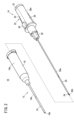
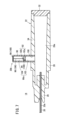
本発明の一実施形態に係るカテーテル組立体10は、患者(生体)の血管内に輸液(薬液)を投与するための留置針として構成されている。図1及び図2に示すように、カテーテル組立体10は、カテーテル部材12及び穿刺針14を有する。カテーテル部材12は、カテーテルシャフト16と、カテーテルシャフト16の基端部に設けられたカテーテルハブ18とを有する。A
カテーテルシャフト16は、可撓性を有し患者の血管内に持続的に挿入可能な管状部材である。カテーテルシャフト16は、その全長に亘って軸線方向に沿って延在した内腔16aを有する。カテーテルシャフト16の先端には、内腔16aに連通する先端開口16bが形成されている。The
カテーテルシャフト16の構成材料は、特に限定されるものではないが、透明性を有する樹脂材料、特に軟質樹脂材料が好適であり、例えば、ポリテトラフルオロエチレン(PTFE)、エチレン・テトラフルオロエチレン共重合体(ETFE)、ペルフルオロアルコキシフッ素樹脂(PFA)等のフッ素系樹脂、ポリエチレン、ポリプロピレン等のオレフィン系樹脂又はこれらの混合物、ポリウレタン、ポリエステル、ポリアミド、ポリエーテルナイロン樹脂、オレフィン系樹脂とエチレン-酢酸ビニル共重合体との混合物等が挙げられる。The material constituting the
カテーテルハブ18は、中空状(円筒状)に形成されている。カテーテルハブ18の内腔18aには、図示を省略するが、止血弁、シール部材及びプラグが配設される。カテーテルハブ18は、カテーテルハブ18の内腔18aに流入した血液をカテーテルハブ18の外側から視認可能なように透明性を有している。The
カテーテルハブ18は、カテーテルシャフト16よりも硬い材料によって構成されることが好ましい。カテーテルハブ18の構成材料は、特に限定されるものではないが、例えば、ポリプロピレン、ポリカーボネート、ポリアミド、ポリサルホン、ポリアリレート、メタクリレート-ブチレン-スチレン共重合体、ポリウレタン、アクリル樹脂、ABS樹脂等の熱可塑性樹脂を好適に用いることができる。The
穿刺針14は、針体20と、針体20の基端部に設けられた針ハブ22とを備える。針体20は、患者の皮膚を穿刺可能な剛性を有する管状部材である。針体20は、軸線方向に沿って延在した内腔20aを有する。針体20は、カテーテル組立体10の初期状態(組立状態)で、カテーテルシャフト16の内腔16a及びカテーテルハブ18の内腔18aに挿通される(図1参照)。The
針体20の構成材料としては、例えば、ステンレス鋼、アルミニウム、アルミニウム合金、チタン、チタン合金のような金属材料が挙げられる。針体20は、カテーテルシャフト16に比べて充分に長く形成され、カテーテル組立体10の初期状態においてカテーテルシャフト16の先端開口16bから突出している(図1参照)。The
図1及び図2において、針体20の先端部には、針体20の軸線に対して傾斜した刃面24が形成されている。刃面24には、針体20の内腔20aに連通する先端開口20bが形成されている。1 and 2, a
図2及び図3において、針ハブ22は、中空状(筒状)に形成されている。針ハブ22の構成材料は、上述したカテーテルハブ18の構成材料と同様のものが挙げられる。針ハブ22の全長は、3cm以上7cm以下に設定されるのが好ましく、4cm以上5cm以下に設定されるのがさらに好ましい。2 and 3, the
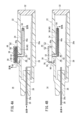
針ハブ22は、その先端部を形成する針体支持部26と、針体支持部26から基端側に延出した血液導入部28と、血液導入部28に設けられてユーザが視認可能な視認部30とを有する。針体支持部26には、針体20の基端部が固着される。血液導入部28は、外側から内部を視認することができないように不透明に形成されている。ただし、血液導入部28は、透明性を有してもよい。The
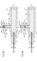
図3において、血液導入部28には、針体20の血管確保時に針体20の内腔20aを介して血液が導入されるチャンバ28aが形成されている。血液導入部28の基端開口は、封止部材32によって液密及び気密に封止されている。血液導入部28は、穿刺針14又はカテーテル組立体10を操作する際の操作部としても機能する。3, the
視認部30は、刃面24を上方に向けた際に、血液導入部28の壁部のうち上方に位置する側壁部34に設けられている(図1及び図2参照)。側壁部34と刃面24とは、針体20の周方向の位置が同じである。視認部30は、視認マーカ36と、視認マーカ36を移動可能に収容する収容部38とを有する。視認マーカ36は、血液とは異なる色(赤色以外の色)に着色された着色液体40である。着色液体40の詳細については後述する。The
収容部38は、チャンバ28a内に設けられた第1収容部42と、血液導入部28の外側に設けられた第2収容部44とを含む。第1収容部42は、針体20の軸線方向に沿って延在した第1管状部46と、第1管状部46から延出して血液導入部28の側壁部34に固定された第2管状部48とを有する。The
第1管状部46の一端部(針体支持部26側の端部)には、第2管状部48が連結している。第1管状部46の第1内腔46aは、着色液体40の全体が収容可能な大きさに設定されている。第1管状部46の他端部(封止部材32側の端部)には、チャンバ28a内と第1内腔46aとの間の空気の連通を許可する一方でチャンバ28aから第1内腔46aへの血液の流入を阻止するフィルタ部50が設けられている。フィルタ部50としては、例えば、疎水性フィルタを用いることができる。フィルタ部50は、第1管状部46の他端部に対して液密且つ気密に固着されている。
The second
第2管状部48は、第1管状部46の一端部から第1管状部46の延在方向と交差する方向(例えば、直交する方向)に延出している。第2管状部48は、血液導入部28の側壁部34に形成された貫通孔52に挿入されている。第2管状部48の外周面は、貫通孔52の内周面に対して液密且つ気密に固着されている。第2管状部48の第2内腔48aは、第1内腔46aと第2収容部44の内腔44aとを互いに連通する。The second
第2収容部44の内腔44aは、着色液体40の全体が収容可能な大きさに設定されている。具体的に、第2収容部44の内腔44aの体積は、第1内腔46aの体積と略同一である。第2収容部44は、外部から内部が視認可能なように透明性を有している。The
第2収容部44は、血液導入部28の側壁部34の外面から外方に突出した周壁部54と、周壁部54の突出端部に設けられた天壁部56とを含む。周壁部54に形成された開口部58には、空気流通部60が設けられている。空気流通部60は、第2収容部44の内腔44aと針ハブ22の外側空間との間の空気の流通を許可する一方で第2収容部44の内腔44aから外側空間への着色液体40の流通を阻止する。空気流通部60としては、例えば、疎水性フィルタを用いることができる。空気流通部60は、開口部58の内面に対して液密且つ気密に固着されている。空気流通部60は、周壁部54ではなく天壁部56に設けられてもよい。The
視認マーカ36は、第1管状部46の第1内腔46a(第1位置)と第2収容部44の内腔44a(第2位置)とに可逆的に移動可能である。視認マーカ36は、チャンバ28a内の圧力上昇により、第1位置から第2位置に移動する(図4A参照)。また、視認マーカ36は、チャンバ28a内の圧力が低下すると、視認マーカ36の自重と大気圧によって第2位置から第1位置に戻る(図4B参照)。The
着色液体40の液柱圧は、血圧よりも小さい。これにより、着色液体40は、チャンバ28aへの血液の流入により(血圧により)第1位置から第2位置に移動可能となる。着色液体40は、例えば、水銀、テトラブロモエタン等の比較的比重の大きなものを用いることができる。この場合、着色液体40は、自重によって第2位置から第1位置に戻りやすくなる。また、着色液体40は、例えば、グリセリン水溶液等の比較的比重の小さなものを用いることもできる。この場合、視認マーカ36は、チャンバ28a内の圧力上昇によって第1位置から第2位置に移動し易くなる。The liquid column pressure of the colored
次に、カテーテル組立体10を用いた血管穿刺の手技について説明する。なお、図4A及び図4Bにおいて、カテーテル部材12の図示は省略している。後述する図6A、図6B、図8A、図8B、図10A及び図10Bについても同様である。Next, a procedure for puncturing a blood vessel using the
図1に示すように、カテーテル組立体10の初期状態で、刃面24は、上方に向いた状態でカテーテルシャフト16の先端開口16bから先端方向に突出している。また、カテーテル組立体10の初期状態で、視認マーカ36は、第1管状部46の第1内腔46a(第1位置)に位置する(図3参照)。つまり、ユーザは、第2収容部44の内腔44aに視認マーカ36を視認することができない(又は視認マーカ36を視認し難い)。すなわち、視認部30は、針体20の血管未確保を示す第1状態になっている。As shown in Figure 1, in the initial state of the
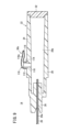
ユーザは、カテーテル組立体10を初期状態のまま皮膚を介して血管に穿刺する。そして、針体20の先端開口20bが血管内に位置すると、血管内の血液は、針体20の内腔20aを介して血液導入部28のチャンバ28a内に流入する。そうすると、図4Aに示すように、チャンバ28a内の圧力が上昇するため、チャンバ28a内の空気は、フィルタ部50を介して第1位置にある視認マーカ36を針体20の先端側に押圧する。なお、第1管状部46の流路断面積は、十分に小さく、フィルタ部50の断面積と同一或いはそれ未満である。そのため、チャンバ28a内の空気は、視認マーカ36を効果的に押圧することができる。The user punctures the blood vessel through the skin with the
空気により押された視認マーカ36は、第2管状部48の第2内腔48aを介して第2収容部44の内腔44a(第2位置)に移動する。この際、第2内腔48a及び第2収容部44の内腔44aに存在していた空気は、空気流通部60を介して針ハブ22の外側空間に排出される。これにより、視認部30は、針体20の血管未確保を示す第1状態から血管確保を示す第2状態に見え方が変化する。そして、ユーザは、視認部30の第2状態(第2収容部44の内腔44aに視認マーカ36が位置する状態)を視認することにより、針体20が血管確保状態であることを知ることができる。The
一方、血管確保状態であった針体20が血管未確保状態になった(例えば、針体20の先端開口20bが血管から外れた場所に位置した)場合、針体20の内腔20aの血液に血圧が作用しなくなる。そのため、針体20の内腔20aに存在していた血液は、大気圧と視認マーカ36の自重とによって針体20の外側に押し出される。On the other hand, when the
この際、図4Bに示すように、チャンバ28a内の圧力が低下するため、第2収容部44の内腔44a(第2位置)にあった視認マーカ36は、大気圧と視認マーカ36の自重とによって第2管状部48の第2内腔48aを介して第1管状部46の第1内腔46a(第1位置)に戻される。これにより、ユーザは、視認部30の第1状態(第2収容部44の内腔44aに視認マーカ36が位置しなくなった状態)を視認することにより、針体20が血管未確保状態であることを知ることができる。At this time, as shown in Fig. 4B, the pressure in the
図4Bの状態において、針体20の血管確保が再度なされると、視認部30は、図4Aの状態になる。つまり、視認部30の見え方は、第1状態から第2状態に変化する。そのため、ユーザは、針体20の血管確保を継続的に確認し続けることができる。
When the
本実施形態に係る穿刺針14及びカテーテル組立体10は、以下の効果を奏する。The
穿刺針14において、針ハブ22は、針体20の血管確保時に針体20の内腔20aを介して血液が導入されるチャンバ28aが形成された血液導入部28と、血液導入部28に設けられてユーザが視認可能な視認部30と、を備える。視認部30は、チャンバ28a内の圧力上昇により、第1状態から第2状態に見え方が変化し、チャンバ28a内の圧力低下により、第2状態から第1状態に戻る。In the
このような構成によれば、針体20の血管確保によりチャンバ28a内に血液が流入すると、チャンバ28a内の圧力が上昇するため、視認部30の見え方が第1状態から第2状態に変化する。この場合、ユーザは、視認部30の第2状態を視認することにより、針体20の血管確保を知ることができる。
With this configuration, when blood flows into the
一方、血管確保状態の針体20が血管未確保状態になると、針体20の内腔20aに血圧が作用しなくなるため、チャンバ28a内の圧力が低下して視認部30の見え方が第2状態から第1状態に戻る。この場合、ユーザは、視認部30の第1状態を視認することにより、針体20の血管未確保を知ることができる。On the other hand, when the
このように、視認部30の見え方は、チャンバ28a内の圧力に応じて第1状態と第2状態とに可逆的に変化する。これにより、針体20の血管確保を継続的に確認し続けることができる。また、ユーザは、チャンバ28a内の血液流入(血液の流れ)を視認する必要がないため(血流確認時間を長くする必要がないため)、血液導入部28の小型化を図ることができる。
In this way, the visibility of the
視認部30は、視認マーカ36と、視認マーカ36を収容する収容部38とを有する。視認マーカ36は、チャンバ28a内の圧力の変化により、視認部30が第1状態となる第1位置と視認部30が第2状態となる第2位置とに可逆的に移動可能である。収容部38は、第2位置にある視認マーカ36を外側から視認可能なように形成されている。The
このような構成によれば、視認マーカ36が第1位置と第2位置とに移動することにより、視認部30の見え方を効果的に変化させることができる。
With this configuration, the
視認部30は、収容部38内とチャンバ28aとの間の空気の流通を許可する一方でチャンバ28aから収容部38内の血液の流入を阻止するフィルタ部50を備える。The
このような構成によれば、チャンバ28a内の空気の圧力を、フィルタ部50を介して視認マーカ36に直接作用させて視認マーカ36を第1位置から第2位置に移動させることができる。また、フィルタ部50により、チャンバ28a内に流入した血液が収容部38内に流入することを阻止することができる。
With this configuration, the air pressure in the
視認部30は、収容部38に設けられた空気流通部60を有する。空気流通部60は、視認マーカ36が第1位置から第2位置に移動する際に収容部38内の空気を針ハブ22の外側空間に排出する。The
このような構成によれば、視認マーカ36を第1位置から第2位置に円滑に移動させることができる。
With this configuration, the
視認マーカ36は、着色液体40である。
The
このような構成によれば、視認マーカ36を収容部38の形状に合わせて変形させることができるため、収容部38の設計の自由度が向上する。
With this configuration, the
上述した穿刺針14及びカテーテル組立体10において、視認部30は、空気流通部60を有しなくてもよい。この場合、視認マーカ36は、針体20の血管確保時に、第2収容部44の内腔44aの空気を圧縮しながら第1位置から第2位置に移動する。また、視認マーカ36は、針体20の血管未確保時に、第2収容部44の内腔44aの圧縮された空気の圧力と視認マーカ36の自重とによって、第2位置から第1位置に移動する。In the above-described
(第1変形例)
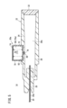
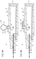
次に、第1変形例に係る視認部30aについて説明する。図5に示すように、本変形例に係る視認部30aは、収容部70、視認マーカ72、空気流通部74、弾性体76及びフィルタ部78を備える。
(First Modification)
Next, a
収容部70は、筒状に形成されている。収容部70は、血液導入部28の側壁部34の外面に形成された凹部82に設けられている。収容部70は、収容部70の一部が凹部82から外方に突出するように凹部82に挿入されている。収容部70のうち少なくとも凹部82から突出している部位は、外側から内部を視認可能なように透明性を有している。収容部70は、凹部82を形成する壁面に対して液密且つ気密に固着されている。なお、収容部70は、血液導入部28に対して一体成形されてもよい。The
視認マーカ72は、収容部70の軸線方向に移動可能な状態で収容部70の内腔70aに配設されたピストン(固体)である。視認マーカ72は、収容部70の内腔70aを、収容部70の一端側の第1空間84と他端側の第2空間86とに仕切る(図6A参照)。視認マーカ72は、収容部70の内周面に対して摺動する。視認マーカ72は、収容部70の内周面に対して液密且つ気密に接触する。視認マーカ72は、収容部70の一端側(血液導入部28側)の第1位置と収容部70の他端側(空気流通部74側)の第2位置とに可逆的に移動可能である。The
視認マーカ72は、第1位置で血液導入部28の凹部82内に位置する。そのため、ユーザは、第1位置にある視認マーカ72を針ハブ22の外側から見難い。一方、視認マーカ72は、第2位置で凹部82の外側に位置する。そのため、ユーザは、第2位置にある視認マーカ72を針ハブ22の外側から見易い。The
空気流通部74は、収容部70の他端部(突出端部)を形成する。空気流通部74は、第2空間86と針ハブ22の外側空間との間の空気の流通を許可する一方で血液の流通を阻止する。空気流通部74としては、例えば、疎水性フィルタを用いることができる。The
弾性体76は、収容部70の第2空間86に配設されている。換言すれば、弾性体76は、視認マーカ72と空気流通部74との間に介設されている。弾性体76は、視認マーカ72を収容部70の一端側(血液導入部28側)に付勢する。弾性体76は、ばね部材である。ただし、弾性体76は、弾性変形可能なゴム部材であってもよい。弾性体76は、視認マーカ72を第2位置から第1位置に復帰させるための復帰手段77として機能する。The
フィルタ部78は、血液導入部28の側壁部34に形成されてチャンバ28aと収容部70の内腔70a(第1空間84)とを互いに連通する貫通孔88に配設されている。フィルタ部78は、チャンバ28aと収容部70の第1空間84との間の空気の連通を許可する一方でチャンバ28aから収容部70の第1空間84への血液の流入を阻止する。フィルタ部78としては、例えば、疎水性フィルタを用いることができる。フィルタ部78は、貫通孔88の内面に対して液密且つ気密に固着されている。The
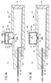
視認部30aにおいて、カテーテル組立体10の初期状態で、視認マーカ72は、収容部70の一端側の第1位置にある(図5参照)。図6Aに示すように、針体20の血管確保によりチャンバ28a内に血液が流入してチャンバ28a内の圧力が上昇すると、視認マーカ72は、チャンバ28a内の空気に押されて収容部70の一端側の第1位置から他端側の第2位置に移動する。この際、弾性体76は、視認マーカ72に押されて弾性変形(圧縮変形)する。また、視認マーカ72と空気流通部74との間の空気は、視認マーカ72に押されて空気流通部74を介して外側空間に排出される。In the
すなわち、視認部30aは、針体20の血管未確保を示す第1状態(視認マーカ72が第1位置にある状態)から針体20の血管確保を示す第2状態(視認マーカ72が第2位置にある状態)に見え方が変化する。これにより、ユーザは、視認部30aの第2状態を視認することにより、針体20の血管確保を知ることができる。That is, the visibility of the
一方、血管確保状態であった針体20が血管未確保状態になった場合、チャンバ28a内の圧力が低下する。そうすると、図6Bに示すように、第2位置にあった視認マーカ72は、視認マーカ72の自重、弾性体76の弾性力(復元力)及び大気圧により第1位置に戻される。これにより、ユーザは、視認部30aの第1状態を視認することにより、針体20が血管未確保状態であることを知ることができる。On the other hand, when the
図6Bの状態において、針体20の血管確保が再度なされると、視認部30aは、図6Aの状態になる。つまり、視認部30aの見え方は、第1状態から第2状態に変化する。そのため、ユーザは、針体20の血管確保を継続的に確認し続けることができる。
When the
本変形例において、視認部30aは、視認マーカ72を第2位置から第1位置に復帰させる復帰手段77を有する。In this modified example, the
このような構成によれば、復帰手段77により視認マーカ72を第2位置から第1位置に容易に復帰させることができる。
With this configuration, the return means 77 can easily return the
視認マーカ72は、固体であって、復帰手段77は、収容部70内に設けられて視認マーカ72の第1位置から第2位置への移動によって弾性変形する弾性体76を有する。The
このような構成によれば、弾性体76の復元力により視認マーカ72を第2位置から第1位置に容易に復帰させることができる。
With this configuration, the restoring force of the
視認部30aは、空気流通部74を有しなくてもよい。この場合、収容部70の突出端部は、空気及び血液を流通しない壁部により形成される。そうすると、視認マーカ72は、収容部70の第2空間86の空気を圧縮しながら第1位置から第2位置に移動する。また、視認マーカ72は、圧縮された第2空間86の空気の圧力と弾性体76の復元力とによって、第2位置から第1位置に移動する。このような形態の場合、収容部70の第2空間86の空気と弾性体76とは、視認マーカ72を第2位置から第1位置に復帰させるための復帰手段77として機能する。The
(第2変形例)
次に、第2変形例に係る視認部30bについて説明する。図7に示すように、本変形例に係る視認部30bは、筒状部90、視認マーカ92、フィルタ部94、吊り下げ部96及び空気流通部98を備える。
(Second Modification)
Next, a
筒状部90は、血液導入部28の側壁部34から外方に突出するように側壁部34に設けられている。具体的に、筒状部90は、血液導入部28の側壁部34に形成された貫通孔100に挿入されている。筒状部90のうち少なくとも貫通孔100から突出している部分は、外側から内部が視認可能なように透明性を有している。筒状部90のうち貫通孔100に挿入されている部分は、貫通孔100の内周面に対して液密且つ気密に接触している。なお、筒状部90は、血液導入部28に対して一体成形されてもよい。The
視認マーカ92は、筒状部90の軸線方向に移動可能な状態で筒状部90の内腔90aに配設されたマーカ本体92aと、マーカ本体92aに設けられた錘部92bとを有する。マーカ本体92aは、筒状部90の内周面に対して摺動する。マーカ本体92aは、筒状部90の内周面に対して液密且つ気密に接触する。マーカ本体92aは、筒状部90の内腔90aを、筒状部90の一端側の第1空間102と筒状部90の他端側の第2空間104とに仕切る。筒状部90の第1空間102は、チャンバ28aに連通する。The
錘部92bは、視認マーカ92における血液導入部28とは反対側の面に固定されている。視認マーカ92の比重(マーカ本体92aと錘部92bとを合わせたものの比重)は、血液の比重よりも軽い。すなわち、視認マーカ92は、血液に対して浮くように形成されている。視認マーカ92は、チャンバ28a内の圧力の変化により(筒状部90内の血液の液面の変化により)、視認部30bが第1状態となる第1位置と視認部30bが第2状態となる第2位置とに可逆的に移動可能である。The
フィルタ部94は、マーカ本体92aに設けられている。フィルタ部94は、筒状部90の第1空間102と第2空間104との間の空気の流通を許可する一方で第1空間102から第2空間104への血液の流通を阻止する。フィルタ部94としては、例えば、疎水性フィルタを用いることができる。The
吊り下げ部96は、筒状部90の突出端部(空気流通部98)に設けられ、針体20の血管未確保の状態で視認マーカ92を第1位置に吊り下げるためのものである。吊り下げ部96は、視認マーカ92が第1位置から第2位置に移動することにより弾性変形する弾性体106である。弾性体106としては、例えば、ばね又はゴム等が用いられる。吊り下げ部96は、弾性体106に限定されず、例えば、糸であってもよい。The hanging
吊り下げ部96の一端は、錘部92bに固着され、吊り下げ部96の他端は、空気流通部98に固着されている。吊り下げ部96の長さは、視認マーカ92に血液が接触していない状態で、筒状部90の軸線方向の中間に位置するように設定される。ただし、吊り下げ部96の長さは、適宜設定可能である。One end of the hanging
空気流通部98は、筒状部90の突出端部を形成する。空気流通部98は、筒状部90の第2空間104と針ハブ22の外側空間との間の空気の流通を許可する一方で第2空間104から外側空間への血液の流出を阻止する。空気流通部98としては、例えば、疎水性フィルタを用いることができる。フィルタ部94と空気流通部98とは、チャンバ28a内の空気を外部に逃がすための空気逃がし部108を形成する。The
視認部30bにおいて、カテーテル組立体10の初期状態で、視認マーカ92は、筒状部90の軸線方向の途中の第1位置にある(図7参照)。また、筒状部90の第1空間102には、血液が存在していない。In the initial state of the
図8Aに示すように、針体20の血管確保によりチャンバ28aに血液が流入すると、チャンバ28a内の空気は、筒状部90の第1空間102からフィルタ部94、第2空間104及び空気流通部98を介して外側空間に排出される。そして、血液は、チャンバ28a内を満たした後で筒状部90の第1空間102に流入し、マーカ本体92aに接触する。As shown in Figure 8A, when blood flows into the
そうすると、マーカ本体92aは、血液により上方に押圧されて第1位置から筒状部90の他端側の第2位置に移動する。この際、筒状部90の第2空間104の空気が空気流通部98を介して外部に排出されるとともに吊り下げ部96が弾性変形する。Then, the
すなわち、視認部30bは、針体20の血管未確保を示す第1状態(視認マーカ92が第1位置にあるとともに第1空間102に血液が存在しない状態)から針体20の血管確保を示す第2状態(視認マーカ92が第2位置にあるとともに第1空間102に血液が存在する状態)に見え方が変化する。そのため、ユーザは、視認部30bの第2状態を視認することにより、針体20の血管確保を知ることができる。That is, the visibility of the
一方、血管確保状態であった針体20が血管未確保状態になった場合、筒状部90内の血液の液柱圧や大気圧によりチャンバ28a内の血液が針体20の内腔20aを介して外部に押し出されるため、チャンバ28a内の圧力が低下する。そうすると、図8Bに示すように、視認マーカ92は、視認マーカ92の自重(マーカ本体92aの自重及び錘部92bの自重)、弾性体106(吊り下げ部96)の復元力及び大気圧により第2位置から第1位置に移動する。この際、視認マーカ92は、吊り下げ部96によって第1位置に停止する。そのため、ユーザは、視認部30bの第1状態を視認することにより、針体20が血管未確保状態であることを知ることができる。On the other hand, when the
図8Bの状態において、針体20の血管確保が再度なされると、視認部30bは、図8Aの状態になる。つまり、視認部30bの見え方は、第1状態から第2状態に変化する。そのため、ユーザは、針体20の血管確保を継続的に確認し続けることができる。
When the
本変形例において、視認部30bは、血液導入部28から外方に突出するように当該血液導入部28に設けられた筒状部90を有する。筒状部90のうち少なくとも血液導入部28から突出している部分は、外部から内部が視認可能なように形成されている。筒状部90の内腔90a(第1空間102)は、チャンバ28aに連通している。視認部30bには、チャンバ28a内の空気を外部に逃がすための空気逃がし部108が設けられている。In this modified example, the
このような構成によれば、針体20の血管確保時に、筒状部90の内腔90a(第1空間102)に血液を流入させることができる。また、針体20の血管未確保時に、筒状部90の内腔90a(第1空間102)から血液をチャンバ28a側に流出させることができる。そのため、筒状部90の内腔90aの血液によって、視認部30bの見え方を第1状態と第2状態とに変化させることができる。
With this configuration, when the
筒状部90の突出端部には、筒状部90の内腔90aと筒状部90の外側空間との間の空気の流通を許可する一方で筒状部90の内腔90aから外側空間への血液の流出を阻止する空気流通部98が設けられている。An
このような構成によれば、筒状部90の内腔90aに血液を円滑に流入させることができる。
With this configuration, blood can flow smoothly into the
視認部30bは、筒状部90の内腔90aに設けられて血液よりも比重の軽い視認マーカ92を有している。視認マーカ92は、チャンバ28a内の圧力の変化により、視認部30bが第1状態となる第1位置と視認部30bが第2状態となる第2位置とに可逆的に移動可能である。The
このような構成によれば、視認マーカ92が第1位置と第2位置とに移動することにより、視認部30bの見え方を効果的に変化させることができる。
With this configuration, the
視認部30bは、筒状部90の端部に設けられて視認マーカ92を吊るすための吊り下げ部96を有している。視認マーカ92は、筒状部90の内周面に対して液密且つ気密に接触した状態で筒状部90の軸線方向に沿って摺動可能に設けられている。The
このような構成によれば、筒状部90の内腔90aに血液が流入していない状態で吊り下げ部96により視認マーカ92を第1位置に位置させることができる。
With this configuration, the
吊り下げ部96は、視認マーカ92の第1位置から第2位置への移動によって弾性変形する弾性体106である。The hanging
このような構成によれば、弾性体106の復元力により、視認マーカ92を第2位置から第1位置に円滑に戻すことができる。
With this configuration, the restoring force of the
空気逃がし部108は、フィルタ部94と空気流通部98とで形成されなくてもよい。空気逃がし部108は、フィルタ部94と同様に構成された疎水性フィルタを血液導入部28又は封止部材32に設けてもよい。視認マーカ92は、錘部92bを有しなくてもよい。つまり、視認マーカ92は、マーカ本体92aの重量により比重を調整してもよい。The
(第3変形例)
次に、第3変形例に係る視認部30cについて説明する。図9に示すように、本変形例に係る視認部30cは、チャンバ28a内の圧力の変化により拡張及び収縮するバルーン110を有する。
(Third Modification)
Next, a
バルーン110は、ゴム等の弾性材料によって袋状に形成されている。バルーン110は、血液導入部28の側壁部34から外方に突出した突起112に固着される固定部114と、固定部114に設けられたバルーン本体116とを含む。突起112には、チャンバ28aとバルーン本体116の内腔116aとを互いに連通する貫通孔118が形成されている。固定部114は、突起112に対して気密に固着されている。バルーン本体116は、内圧が上昇することにより拡張し(膨らみ)、内圧が低下することにより収縮する(萎む)。The
視認部30cにおいて、カテーテル組立体10の初期状態で、バルーン本体116は収縮している(図9参照)。図10Aに示すように、針体20の血管確保によりチャンバ28a内に血液が流入してチャンバ28a内の圧力が上昇すると、バルーン本体116の内圧が上昇するため、バルーン本体116が拡張する。In the
すなわち、視認部30cは、針体20の血管未確保を示す第1状態(バルーン本体116が収縮した状態)から針体20の血管確保を示す第2状態(バルーン本体116が拡張した状態)に見え方が変化する。これにより、ユーザは、視認部30cの第2状態を視認することにより、針体20の血管確保を知ることができる。That is, the visibility of the visualizing
一方、血管確保状態であった針体20が血管未確保状態になった場合、チャンバ28a内の圧力が低下する。そうすると、図10Bに示すように、バルーン本体116の内圧が低下するため、バルーン本体116が収縮する。これにより、ユーザは、視認部30cの第1状態を視認することにより、針体20が血管未確保状態であることを知ることができる。On the other hand, when the
図10Bの状態において、針体20の血管確保が再度なされると、視認部30cは、図10Aの状態になる。つまり、視認部30cの見え方は、第1状態から第2状態に変化する。そのため、ユーザは、針体20の血管確保を継続的に確認し続けることができる。
When the
本変形例において、視認部30cは、チャンバ28a内の圧力の変化により拡張及び収縮するバルーン110を有する。In this modified example, the
このような構成によれば、ユーザは、バルーン110の拡張及び収縮を視認することにより、針体20の血管確保及び血管未確保を容易に知ることができる。
With this configuration, the user can easily tell whether the
本発明は上述した実施形態に限定されるものではなく、本発明の要旨を逸脱しない範囲において、種々の改変が可能である。The present invention is not limited to the above-described embodiments, and various modifications are possible without departing from the spirit and scope of the present invention.
以上の実施形態をまとめると、以下のようになる。The above embodiments can be summarised as follows:
上記実施形態は、血管に穿刺するための中空状の針体(20)と前記針体の基端部に設けられた針ハブ(22)とを備えた穿刺針(14)であって、前記針ハブは、前記針体の血管確保時に前記針体の内腔(22a)を介して血液が導入されるチャンバ(28a)が形成された血液導入部(28)と、前記血液導入部に設けられてユーザが視認可能な視認部(30、30a~30c)と、を備え、前記視認部は、前記チャンバ内の圧力上昇により、第1状態から第2状態に見え方が変化し、前記チャンバ内の圧力低下により、前記第2状態から前記第1状態に戻る、穿刺針を開示している。The above embodiment discloses a puncture needle (14) comprising a hollow needle body (20) for puncturing a blood vessel and a needle hub (22) provided at the base end of the needle body, the needle hub comprising a blood introduction section (28) in which a chamber (28a) is formed into which blood is introduced via the inner cavity (22a) of the needle body when the needle body is used to secure a blood vessel, and a viewing section (30, 30a-30c) provided in the blood introduction section and visible to the user, the viewing section changing its appearance from a first state to a second state as pressure in the chamber increases, and returning from the second state to the first state as pressure in the chamber decreases.
上記の穿刺針において、前記視認部は、視認マーカ(36、72)と、前記視認マーカを収容する収容部(38、70)と、を有し、前記視認マーカは、前記チャンバ内の圧力の変化により、前記視認部が前記第1状態となる第1位置と前記視認部が前記第2状態となる第2位置とに可逆的に移動可能であり、前記収容部は、前記第2位置にある前記視認マーカを外側から視認可能なように形成されてもよい。In the above puncture needle, the viewing portion has a viewing marker (36, 72) and a storage portion (38, 70) for storing the viewing marker, and the viewing marker is reversibly movable between a first position where the viewing portion is in the first state and a second position where the viewing portion is in the second state due to a change in pressure in the chamber, and the storage portion may be formed so that the viewing marker in the second position can be viewed from the outside.
上記の穿刺針において、前記視認部は、前記収容部内と前記チャンバとの間の空気の流通を許可する一方で前記チャンバから前記収容部内の血液の流入を阻止するフィルタ部(50、78)を備えてもよい。In the above puncture needle, the viewing portion may be provided with a filter portion (50, 78) that allows air to flow between the storage portion and the chamber while preventing blood from flowing from the chamber into the storage portion.
上記の穿刺針において、前記視認部は、前記収容部に設けられた空気流通部(60、74)を有し、前記空気流通部は、前記視認マーカが前記第1位置から前記第2位置に移動する際に前記収容部内の空気を前記針ハブの外側空間に排出してもよい。In the above puncture needle, the visibility portion has an air circulation portion (60, 74) provided in the storage portion, and the air circulation portion may exhaust air within the storage portion into the outer space of the needle hub when the visibility marker moves from the first position to the second position.
上記の穿刺針において、前記視認マーカは、着色液体(40)であってもよい。In the above puncture needle, the visual marker may be a colored liquid (40).
上記の穿刺針において、前記視認部は、前記視認マーカを前記第2位置から前記第1位置に復帰させるための復帰手段(77)を有してもよい。In the above puncture needle, the visualization portion may have a return means (77) for returning the visualization marker from the second position to the first position.
上記の穿刺針において、前記視認マーカは、固体であって、前記復帰手段は、前記収容部内に設けられて前記視認マーカの前記第1位置から前記第2位置への移動によって弾性変形する弾性体(76)を有してもよい。In the above puncture needle, the visual marker may be a solid, and the return means may have an elastic body (76) provided in the storage section and elastically deformed by movement of the visual marker from the first position to the second position.
上記の穿刺針において、前記視認部は、前記血液導入部から外方に突出するように当該血液導入部に設けられた筒状部(90)を有し、前記筒状部のうち少なくとも前記血液導入部から突出している部分は、外側から内部が視認可能なように形成され、前記筒状部の内腔は、前記チャンバに連通し、前記視認部には、前記チャンバ内の空気を外部に逃がすための空気逃がし部(108)が設けられてもよい。In the above puncture needle, the viewing portion has a tubular portion (90) provided in the blood introduction portion so as to protrude outward from the blood introduction portion, at least the portion of the tubular portion protruding from the blood introduction portion is formed so that the inside can be viewed from the outside, the inner cavity of the tubular portion is connected to the chamber, and the viewing portion may be provided with an air escape portion (108) for venting air in the chamber to the outside.
上記の穿刺針において、前記筒状部の突出端部には、前記筒状部の前記内腔と前記筒状部の外側空間との間の空気の流通を許可する一方で前記筒状部の前記内腔から前記外側空間への血液の流出を阻止する空気流通部(98)が設けられてもよい。In the above puncture needle, the protruding end of the tubular portion may be provided with an air flow section (98) that allows air to flow between the inner cavity of the tubular portion and the outer space of the tubular portion while preventing blood from flowing out from the inner cavity of the tubular portion to the outer space.
上記の穿刺針において、前記視認部は、前記筒状部の内腔(90a)に設けられて血液よりも比重の軽い視認マーカ(92)を有し、前記視認マーカは、前記チャンバ内の圧力の変化により、前記視認部が前記第1状態となる第1位置と前記視認部が前記第2状態となる第2位置とに可逆的に移動可能であってもよい。In the above puncture needle, the viewing portion has a viewing marker (92) provided in the inner cavity (90a) of the tubular portion and having a specific gravity lighter than blood, and the viewing marker may be reversibly movable between a first position where the viewing portion is in the first state and a second position where the viewing portion is in the second state due to a change in pressure in the chamber.
上記の穿刺針において、前記視認部は、前記筒状部の突出端部に設けられて前記視認マーカを吊るすための吊り下げ部(96)を有し、前記視認マーカは、前記筒状部の内周面に対して液密且つ気密に接触した状態で前記筒状部の軸線方向に沿って摺動可能に設けられてもよい。In the above puncture needle, the visualization portion has a hanging portion (96) provided at the protruding end of the tubular portion for hanging the visualization marker, and the visualization marker may be arranged to be slidable along the axial direction of the tubular portion while in liquid-tight and airtight contact with the inner surface of the tubular portion.
上記の穿刺針において、前記吊り下げ部は、前記視認マーカの前記第1位置から前記第2位置への移動によって弾性変形する弾性体(106)であってもよい。In the above puncture needle, the hanging portion may be an elastic body (106) that elastically deforms upon movement of the visual marker from the first position to the second position.
上記の穿刺針において、前記視認部は、前記チャンバ内の圧力の変化により拡張及び収縮するバルーン(110)を有してもよい。In the above puncture needle, the viewing portion may have a balloon (110) that expands and contracts due to changes in pressure in the chamber.
本実施形態は、上述した穿刺針と、前記針体が挿通される内腔を有するカテーテルシャフト(16)と、前記カテーテルシャフトの基端部に設けられたカテーテルハブ(18)と、を備える、カテーテル組立体(10)を開示している。This embodiment discloses a catheter assembly (10) comprising the above-mentioned puncture needle, a catheter shaft (16) having an inner cavity through which the needle body is inserted, and a catheter hub (18) provided at the base end of the catheter shaft.
Claims (12)
前記針ハブは、
前記針体の血管確保時に前記針体の内腔を介して血液が導入されるチャンバが形成された血液導入部と、
前記血液導入部に設けられてユーザが視認可能な視認部と、を備え、
前記視認部は、前記チャンバ内の圧力上昇により、第1状態から第2状態に見え方が変化し、前記チャンバ内の圧力低下により、前記第2状態から前記第1状態に戻り、
前記視認部は、
視認マーカと、
前記視認マーカを収容する収容部と、を有し、
前記視認マーカは、前記チャンバ内の圧力の変化により、前記視認部が前記第1状態となる第1位置と前記視認部が前記第2状態となる第2位置とに可逆的に移動可能であり、
前記収容部は、前記第2位置にある前記視認マーカを外側から視認可能なように形成され、
前記視認部は、前記収容部内と前記チャンバとの間の空気の流通を許可する一方で前記チャンバから前記収容部内の血液の流入を阻止するフィルタ部を備える、穿刺針。 A puncture needle having a hollow needle body for puncturing a blood vessel and a needle hub provided at a base end of the needle body,
The needle hub includes:
a blood introduction section in which a chamber is formed into which blood is introduced through an inner cavity of the needle body when the blood vessel is secured by the needle body;
A visual confirmation section provided in the blood guiding section and visible to a user,
an appearance of the visual confirmation portion changes from a first state to a second state due to an increase in pressure within the chamber, and returns from the second state to the first state due to a decrease in pressure within the chamber;
The visual confirmation unit is
A visual marker;
A storage section for storing the visual marker,
the visual marker is reversibly movable between a first position where the visual portion is in the first state and a second position where the visual portion is in the second state, in response to a change in pressure within the chamber;
The storage portion is formed so that the visual marker in the second position can be visually recognized from the outside,
A puncture needle , wherein the viewing portion includes a filter portion that allows air to flow between the storage portion and the chamber while preventing blood from flowing from the chamber into the storage portion .
前記針ハブは、
前記針体の血管確保時に前記針体の内腔を介して血液が導入されるチャンバが形成された血液導入部と、
前記血液導入部に設けられてユーザが視認可能な視認部と、を備え、
前記視認部は、前記チャンバ内の圧力上昇により、第1状態から第2状態に見え方が変化し、前記チャンバ内の圧力低下により、前記第2状態から前記第1状態に戻り、
前記視認部は、
視認マーカと、
前記視認マーカを収容する収容部と、を有し、
前記視認マーカは、前記チャンバ内の圧力の変化により、前記視認部が前記第1状態となる第1位置と前記視認部が前記第2状態となる第2位置とに可逆的に移動可能であり、
前記収容部は、前記第2位置にある前記視認マーカを外側から視認可能なように形成され、
前記視認部は、前記収容部に設けられた空気流通部を有し、
前記空気流通部は、前記視認マーカが前記第1位置から前記第2位置に移動する際に前記収容部内の空気を前記針ハブの外側空間に排出する、穿刺針。 A puncture needle having a hollow needle body for puncturing a blood vessel and a needle hub provided at a base end of the needle body,
The needle hub includes:
a blood introduction section in which a chamber is formed into which blood is introduced through an inner cavity of the needle body when the blood vessel is secured by the needle body;
A visual confirmation section provided in the blood guiding section and visible to a user,
an appearance of the visual confirmation portion changes from a first state to a second state due to an increase in pressure within the chamber, and returns from the second state to the first state due to a decrease in pressure within the chamber;
The visual confirmation unit is
A visual marker;
A storage section for storing the visual marker,
the visual marker is reversibly movable between a first position where the visual portion is in the first state and a second position where the visual portion is in the second state, in response to a change in pressure within the chamber;
The storage portion is formed so that the visual marker in the second position can be visually recognized from the outside,
The visual confirmation section has an air circulation section provided in the storage section,
The air circulation section discharges air within the storage section to the outer space of the needle hub when the visual marker moves from the first position to the second position.
前記針ハブは、
前記針体の血管確保時に前記針体の内腔を介して血液が導入されるチャンバが形成された血液導入部と、
前記血液導入部に設けられてユーザが視認可能な視認部と、を備え、
前記視認部は、前記チャンバ内の圧力上昇により、第1状態から第2状態に見え方が変化し、前記チャンバ内の圧力低下により、前記第2状態から前記第1状態に戻り、
前記視認部は、
視認マーカと、
前記視認マーカを収容する収容部と、を有し、
前記視認マーカは、前記チャンバ内の圧力の変化により、前記視認部が前記第1状態となる第1位置と前記視認部が前記第2状態となる第2位置とに可逆的に移動可能であり、
前記収容部は、前記第2位置にある前記視認マーカを外側から視認可能なように形成され、
前記視認マーカは、着色液体である、穿刺針。 A puncture needle having a hollow needle body for puncturing a blood vessel and a needle hub provided at a base end of the needle body,
The needle hub includes:
a blood introduction section in which a chamber is formed into which blood is introduced through an inner cavity of the needle body when the blood vessel is secured by the needle body;
A visual confirmation section provided in the blood guiding section and visible to a user,
an appearance of the visual confirmation portion changes from a first state to a second state due to an increase in pressure within the chamber, and returns from the second state to the first state due to a decrease in pressure within the chamber;
The visual confirmation unit is
A visual marker;
A storage section for storing the visual marker,
the visual marker is reversibly movable between a first position where the visual portion is in the first state and a second position where the visual portion is in the second state, in response to a change in pressure within the chamber;
The storage portion is formed so that the visual marker in the second position can be visually recognized from the outside,
The visual marker is a colored liquid.
前記針ハブは、
前記針体の血管確保時に前記針体の内腔を介して血液が導入されるチャンバが形成された血液導入部と、
前記血液導入部に設けられてユーザが視認可能な視認部と、を備え、
前記視認部は、前記チャンバ内の圧力上昇により、第1状態から第2状態に見え方が変化し、前記チャンバ内の圧力低下により、前記第2状態から前記第1状態に戻り、
前記視認部は、
視認マーカと、
前記視認マーカを収容する収容部と、を有し、
前記視認マーカは、前記チャンバ内の圧力の変化により、前記視認部が前記第1状態となる第1位置と前記視認部が前記第2状態となる第2位置とに可逆的に移動可能であり、
前記収容部は、前記第2位置にある前記視認マーカを外側から視認可能なように形成され、
前記視認部は、前記視認マーカを前記第2位置から前記第1位置に復帰させるための復帰手段を有する、穿刺針。 A puncture needle having a hollow needle body for puncturing a blood vessel and a needle hub provided at a base end of the needle body,
The needle hub includes:
a blood introduction section in which a chamber is formed into which blood is introduced through an inner cavity of the needle body when the blood vessel is secured by the needle body;
A visual confirmation section provided in the blood guiding section and visible to a user,
an appearance of the visual confirmation portion changes from a first state to a second state due to an increase in pressure within the chamber, and returns from the second state to the first state due to a decrease in pressure within the chamber;
The visual confirmation unit is
A visual marker;
A storage section for storing the visual marker,
the visual marker is reversibly movable between a first position where the visual portion is in the first state and a second position where the visual portion is in the second state, in response to a change in pressure within the chamber;
The storage portion is formed so that the visual marker in the second position can be visually recognized from the outside,
The visualization portion has a return means for returning the visualization marker from the second position to the first position.
前記視認マーカは、固体であって、
前記復帰手段は、前記収容部内に設けられて前記視認マーカの前記第1位置から前記第2位置への移動によって弾性変形する弾性体を有する、穿刺針。 The puncture needle according to claim 4 ,
The visual marker is a solid,
The returning means has an elastic body that is provided in the accommodation portion and elastically deforms in response to movement of the visual marker from the first position to the second position.
前記針ハブは、
前記針体の血管確保時に前記針体の内腔を介して血液が導入されるチャンバが形成された血液導入部と、
前記血液導入部に設けられてユーザが視認可能な視認部と、を備え、
前記視認部は、前記チャンバ内の圧力上昇により、第1状態から第2状態に見え方が変化し、前記チャンバ内の圧力低下により、前記第2状態から前記第1状態に戻り、
前記視認部は、前記血液導入部から外方に突出するように当該血液導入部に設けられた筒状部を有し、
前記筒状部のうち少なくとも前記血液導入部から突出している部分は、外側から内部が視認可能なように形成され、
前記筒状部の内腔は、前記チャンバに連通し、
前記視認部には、前記チャンバ内の空気を外部に逃がすための空気逃がし部が設けられている、穿刺針。 A puncture needle having a hollow needle body for puncturing a blood vessel and a needle hub provided at a base end of the needle body,
The needle hub includes:
a blood introduction section in which a chamber is formed into which blood is introduced through an inner cavity of the needle body when the blood vessel is secured by the needle body;
A visual confirmation section provided in the blood guiding section and visible to a user,
an appearance of the visual confirmation portion changes from a first state to a second state due to an increase in pressure within the chamber, and returns from the second state to the first state due to a decrease in pressure within the chamber;
the visualization portion has a tubular portion provided in the blood guiding portion so as to protrude outward from the blood guiding portion,
At least a portion of the tubular portion protruding from the blood guiding portion is formed so that the inside can be visually confirmed from the outside,
The inner cavity of the cylindrical portion communicates with the chamber,
The puncture needle, wherein the visual confirmation portion is provided with an air release portion for releasing air within the chamber to the outside.
前記筒状部の突出端部には、前記筒状部の前記内腔と前記筒状部の外側空間との間の空気の流通を許可する一方で前記筒状部の前記内腔から前記外側空間への血液の流出を阻止する空気流通部が設けられている、穿刺針。 The puncture needle according to claim 6 ,
A puncture needle, wherein the protruding end of the tubular portion is provided with an air flow portion that allows air to flow between the inner cavity of the tubular portion and the outer space of the tubular portion while preventing blood from flowing out from the inner cavity of the tubular portion to the outer space.
前記視認部は、前記筒状部の内腔に設けられて血液よりも比重の軽い視認マーカを有し、
前記視認マーカは、前記チャンバ内の圧力の変化により、前記視認部が前記第1状態となる第1位置と前記視認部が前記第2状態となる第2位置とに可逆的に移動可能である、穿刺針。 The puncture needle according to claim 6 or 7 ,
the visual recognition portion has a visual recognition marker that is provided in an inner cavity of the tubular portion and has a specific gravity lighter than blood,
A puncture needle, wherein the visual marker is reversibly movable between a first position where the visual portion is in the first state and a second position where the visual portion is in the second state in response to a change in pressure in the chamber.
前記視認部は、前記筒状部の突出端部に設けられて前記視認マーカを吊るすための吊り下げ部を有し、
前記視認マーカは、前記筒状部の内周面に対して液密且つ気密に接触した状態で前記筒状部の軸線方向に沿って摺動可能に設けられている、穿刺針。 The puncture needle according to claim 8 ,
the visual recognition portion has a hanging portion provided at a protruding end of the cylindrical portion for hanging the visual recognition marker,
The visual marker is provided slidably along the axial direction of the cylindrical portion while being in liquid-tight and air-tight contact with the inner surface of the cylindrical portion.
前記吊り下げ部は、前記視認マーカの前記第1位置から前記第2位置への移動によって弾性変形する弾性体である、穿刺針。 The puncture needle according to claim 9 ,
The puncture needle, wherein the hanging portion is an elastic body that is elastically deformed by movement of the visual marker from the first position to the second position.
前記針ハブは、
前記針体の血管確保時に前記針体の内腔を介して血液が導入されるチャンバが形成された血液導入部と、
前記血液導入部に設けられてユーザが視認可能な視認部と、を備え、
前記視認部は、前記チャンバ内の圧力上昇により、第1状態から第2状態に見え方が変化し、前記チャンバ内の圧力低下により、前記第2状態から前記第1状態に戻り、
前記視認部は、前記チャンバ内の圧力の変化により拡張及び収縮するバルーンを有する、穿刺針。 A puncture needle having a hollow needle body for puncturing a blood vessel and a needle hub provided at a base end of the needle body,
The needle hub includes:
a blood introduction section in which a chamber is formed into which blood is introduced through an inner cavity of the needle body when the blood vessel is secured by the needle body;
A visual confirmation section provided in the blood guiding section and visible to a user,
an appearance of the visual confirmation portion changes from a first state to a second state due to an increase in pressure within the chamber, and returns from the second state to the first state due to a decrease in pressure within the chamber;
The viewing portion has a balloon that expands and contracts with changes in pressure in the chamber.
前記針体が挿通される内腔を有するカテーテルシャフトと、
前記カテーテルシャフトの基端部に設けられたカテーテルハブと、を備える、カテーテル組立体。 The puncture needle according to any one of claims 1 to 11 ,
a catheter shaft having an inner cavity through which the needle body is inserted;
a catheter hub provided at a proximal end of the catheter shaft.
Applications Claiming Priority (3)
| Application Number | Priority Date | Filing Date | Title |
|---|---|---|---|
| JP2020050609 | 2020-03-23 | ||
| JP2020050609 | 2020-03-23 | ||
| PCT/JP2021/009034 WO2021192964A1 (en) | 2020-03-23 | 2021-03-08 | Puncture needle and catheter assembly |
Publications (2)
| Publication Number | Publication Date |
|---|---|
| JPWO2021192964A1 JPWO2021192964A1 (en) | 2021-09-30 |
| JP7581329B2 true JP7581329B2 (en) | 2024-11-12 |
Family
ID=77891829
Family Applications (1)
| Application Number | Title | Priority Date | Filing Date |
|---|---|---|---|
| JP2022509505A Active JP7581329B2 (en) | 2020-03-23 | 2021-03-08 | Puncture needle and catheter assembly |
Country Status (2)
| Country | Link |
|---|---|
| JP (1) | JP7581329B2 (en) |
| WO (1) | WO2021192964A1 (en) |
Families Citing this family (1)
| Publication number | Priority date | Publication date | Assignee | Title |
|---|---|---|---|---|
| CN115400330A (en) * | 2022-08-29 | 2022-11-29 | 河北康誉医疗器械有限公司 | Catheter device for cerebral angiography |
Citations (1)
| Publication number | Priority date | Publication date | Assignee | Title |
|---|---|---|---|---|
| JP2004216156A (en) | 2003-01-14 | 2004-08-05 | Radi Medical Systems Ab | Device for visually indicating blood pressure |
Family Cites Families (3)
| Publication number | Priority date | Publication date | Assignee | Title |
|---|---|---|---|---|
| JPS5832774A (en) * | 1981-08-19 | 1983-02-25 | テルモ株式会社 | Staying needle |
| US5501671A (en) * | 1993-11-02 | 1996-03-26 | Novoste Corporation | Vascular blood containment device |
| US8202253B1 (en) * | 2008-10-17 | 2012-06-19 | Wexler Toby J | Method and apparatus for introducing an intravenous catheter |
-
2021
- 2021-03-08 WO PCT/JP2021/009034 patent/WO2021192964A1/en not_active Ceased
- 2021-03-08 JP JP2022509505A patent/JP7581329B2/en active Active
Patent Citations (1)
| Publication number | Priority date | Publication date | Assignee | Title |
|---|---|---|---|---|
| JP2004216156A (en) | 2003-01-14 | 2004-08-05 | Radi Medical Systems Ab | Device for visually indicating blood pressure |
Also Published As
| Publication number | Publication date |
|---|---|
| WO2021192964A1 (en) | 2021-09-30 |
| JPWO2021192964A1 (en) | 2021-09-30 |
Similar Documents
| Publication | Publication Date | Title |
|---|---|---|
| US7011650B2 (en) | Multiple-dose syringe with collapsible container | |
| US5501671A (en) | Vascular blood containment device | |
| US5222948A (en) | Injection port for single-use syringe | |
| ES2672623T3 (en) | Rinse syringe with positive displacement | |
| US5013303A (en) | Constant pressure infusion device | |
| KR970005840B1 (en) | Continuous drug solution injector equipped with balloon | |
| WO2018207758A1 (en) | Valved needle assembly | |
| JP2005516689A (en) | Liquid supply device | |
| JP2000279527A (en) | Indwelling needle assembly and valve element | |
| JP7581329B2 (en) | Puncture needle and catheter assembly | |
| JP2001190683A (en) | Needling tool | |
| JP3892157B2 (en) | Indwelling needle assembly | |
| US20020091361A1 (en) | Multiple-dose syringe | |
| JP2021146026A (en) | Catheter assembly | |
| JP6129825B2 (en) | Catheter assembly | |
| JPWO2015133279A1 (en) | Catheter assembly | |
| JP2000279526A (en) | Indwelling needle assembly and valve element | |
| JP4525528B2 (en) | Medical suction device | |
| JP4812472B2 (en) | Indwelling needle assembly | |
| WO2023280281A1 (en) | Disposable indwelling needle flushing capsule | |
| JP7658364B2 (en) | Needle Assembly | |
| JP2024522567A (en) | Medical devices to assist with needle placement | |
| JP2637579B2 (en) | Balloon infuser | |
| JP7564027B2 (en) | catheter | |
| JPH11342196A (en) | Balloon catheters and catheter aids |
Legal Events
| Date | Code | Title | Description |
|---|---|---|---|
| A621 | Written request for application examination |
Free format text: JAPANESE INTERMEDIATE CODE: A621 Effective date: 20231115 |
|
| A131 | Notification of reasons for refusal |
Free format text: JAPANESE INTERMEDIATE CODE: A131 Effective date: 20240709 |
|
| A521 | Request for written amendment filed |
Free format text: JAPANESE INTERMEDIATE CODE: A523 Effective date: 20240903 |
|
| TRDD | Decision of grant or rejection written | ||
| A01 | Written decision to grant a patent or to grant a registration (utility model) |
Free format text: JAPANESE INTERMEDIATE CODE: A01 Effective date: 20241008 |
|
| A61 | First payment of annual fees (during grant procedure) |
Free format text: JAPANESE INTERMEDIATE CODE: A61 Effective date: 20241030 |
|
| R150 | Certificate of patent or registration of utility model |
Ref document number: 7581329 Country of ref document: JP Free format text: JAPANESE INTERMEDIATE CODE: R150 |