JP7581327B2 - Input unit, input device, and a cover that can be attached to the input unit - Google Patents
Input unit, input device, and a cover that can be attached to the input unit Download PDFInfo
- Publication number
- JP7581327B2 JP7581327B2 JP2022508355A JP2022508355A JP7581327B2 JP 7581327 B2 JP7581327 B2 JP 7581327B2 JP 2022508355 A JP2022508355 A JP 2022508355A JP 2022508355 A JP2022508355 A JP 2022508355A JP 7581327 B2 JP7581327 B2 JP 7581327B2
- Authority
- JP
- Japan
- Prior art keywords
- pattern
- region
- inner region
- input
- touch
- Prior art date
- Legal status (The legal status is an assumption and is not a legal conclusion. Google has not performed a legal analysis and makes no representation as to the accuracy of the status listed.)
- Active
Links
Images


Classifications
-
- G—PHYSICS
- G06—COMPUTING OR CALCULATING; COUNTING
- G06F—ELECTRIC DIGITAL DATA PROCESSING
- G06F3/00—Input arrangements for transferring data to be processed into a form capable of being handled by the computer; Output arrangements for transferring data from processing unit to output unit, e.g. interface arrangements
- G06F3/01—Input arrangements or combined input and output arrangements for interaction between user and computer
- G06F3/03—Arrangements for converting the position or the displacement of a member into a coded form
- G06F3/033—Pointing devices displaced or positioned by the user, e.g. mice, trackballs, pens or joysticks; Accessories therefor
- G06F3/0338—Pointing devices displaced or positioned by the user, e.g. mice, trackballs, pens or joysticks; Accessories therefor with detection of limited linear or angular displacement of an operating part of the device from a neutral position, e.g. isotonic or isometric joysticks
-
- A—HUMAN NECESSITIES
- A63—SPORTS; GAMES; AMUSEMENTS
- A63F—CARD, BOARD, OR ROULETTE GAMES; INDOOR GAMES USING SMALL MOVING PLAYING BODIES; VIDEO GAMES; GAMES NOT OTHERWISE PROVIDED FOR
- A63F13/00—Video games, i.e. games using an electronically generated display having two or more dimensions
- A63F13/20—Input arrangements for video game devices
- A63F13/24—Constructional details thereof, e.g. game controllers with detachable joystick handles
-
- A—HUMAN NECESSITIES
- A63—SPORTS; GAMES; AMUSEMENTS
- A63F—CARD, BOARD, OR ROULETTE GAMES; INDOOR GAMES USING SMALL MOVING PLAYING BODIES; VIDEO GAMES; GAMES NOT OTHERWISE PROVIDED FOR
- A63F13/00—Video games, i.e. games using an electronically generated display having two or more dimensions
- A63F13/90—Constructional details or arrangements of video game devices not provided for in groups A63F13/20 or A63F13/25, e.g. housing, wiring, connections or cabinets
- A63F13/98—Accessories, i.e. detachable arrangements optional for the use of the video game device, e.g. grip supports of game controllers
-
- G—PHYSICS
- G05—CONTROLLING; REGULATING
- G05G—CONTROL DEVICES OR SYSTEMS INSOFAR AS CHARACTERISED BY MECHANICAL FEATURES ONLY
- G05G1/00—Controlling members, e.g. knobs or handles; Assemblies or arrangements thereof; Indicating position of controlling members
-
- G—PHYSICS
- G06—COMPUTING OR CALCULATING; COUNTING
- G06F—ELECTRIC DIGITAL DATA PROCESSING
- G06F3/00—Input arrangements for transferring data to be processed into a form capable of being handled by the computer; Output arrangements for transferring data from processing unit to output unit, e.g. interface arrangements
- G06F3/01—Input arrangements or combined input and output arrangements for interaction between user and computer
- G06F3/03—Arrangements for converting the position or the displacement of a member into a coded form
- G06F3/033—Pointing devices displaced or positioned by the user, e.g. mice, trackballs, pens or joysticks; Accessories therefor
- G06F3/039—Accessories therefor, e.g. mouse pads
-
- H—ELECTRICITY
- H05—ELECTRIC TECHNIQUES NOT OTHERWISE PROVIDED FOR
- H05K—PRINTED CIRCUITS; CASINGS OR CONSTRUCTIONAL DETAILS OF ELECTRIC APPARATUS; MANUFACTURE OF ASSEMBLAGES OF ELECTRICAL COMPONENTS
- H05K5/00—Casings, cabinets or drawers for electric apparatus
- H05K5/02—Details
- H05K5/03—Covers
-
- A—HUMAN NECESSITIES
- A63—SPORTS; GAMES; AMUSEMENTS
- A63F—CARD, BOARD, OR ROULETTE GAMES; INDOOR GAMES USING SMALL MOVING PLAYING BODIES; VIDEO GAMES; GAMES NOT OTHERWISE PROVIDED FOR
- A63F2300/00—Features of games using an electronically generated display having two or more dimensions, e.g. on a television screen, showing representations related to the game
- A63F2300/10—Features of games using an electronically generated display having two or more dimensions, e.g. on a television screen, showing representations related to the game characterized by input arrangements for converting player-generated signals into game device control signals
- A63F2300/1043—Features of games using an electronically generated display having two or more dimensions, e.g. on a television screen, showing representations related to the game characterized by input arrangements for converting player-generated signals into game device control signals being characterized by constructional details
-
- G—PHYSICS
- G05—CONTROLLING; REGULATING
- G05G—CONTROL DEVICES OR SYSTEMS INSOFAR AS CHARACTERISED BY MECHANICAL FEATURES ONLY
- G05G1/00—Controlling members, e.g. knobs or handles; Assemblies or arrangements thereof; Indicating position of controlling members
- G05G1/04—Controlling members for hand actuation by pivoting movement, e.g. levers
- G05G1/06—Details of their grip parts
Landscapes
- Engineering & Computer Science (AREA)
- Multimedia (AREA)
- Human Computer Interaction (AREA)
- General Engineering & Computer Science (AREA)
- Theoretical Computer Science (AREA)
- Physics & Mathematics (AREA)
- General Physics & Mathematics (AREA)
- Microelectronics & Electronic Packaging (AREA)
- Automation & Control Theory (AREA)
- Position Input By Displaying (AREA)
- Switches With Compound Operations (AREA)
Description
本開示はゲーム操作などのために用いられる入力デバイスに設けられる入力ユニットの構造及び入力ユニットに取り付け可能なカバーの構造に関する。 The present disclosure relates to the structure of an input unit provided on an input device used for game operations, etc., and the structure of a cover that can be attached to the input unit.
ゲーム操作に用いられる入力デバイスには、ユーザが指で動かす入力ユニットの一つとして、入力スティックを有しているものがある。入力スティックは、その最上部にユーザの指が触れるタッチ部を有している。入力スティックは、半径方向に倒したり、初期位置を中心にして回転させることができる。特許文献1において、タッチ部は円盤状である。ユーザは親指をタッチ部に載せて、入力スティックを操作する。入力ユニットは、入力スティックの基部に、入力スティックを支持するとともに入力スティックの位置(傾き)を検知するセンサが取り付けられた支持機構を有している。Some input devices used for game operation have an input stick as one of the input units that the user moves with his/her finger. The input stick has a touch part at the top where the user's finger touches. The input stick can be tilted radially or rotated around its initial position. In
入力スティックを初期位置から半径方向に倒すとき、親指はタッチ部の上面を押しながら半径方向の力を加える。入力スティックを初期位置に戻すとき、親指はタッチ部の外縁に対して力を加えることがある。入力スティックを半径方向に倒すときと、入力スティックを初期位置に戻すときのいずれにおいても、親指の力が入力スティックにスムーズに作用するのが望ましい。 When tilting the input stick radially from its initial position, the thumb applies a radial force while pressing against the top surface of the touch area. When returning the input stick to its initial position, the thumb may apply force against the outer edge of the touch area. It is desirable for the force of the thumb to act smoothly on the input stick, both when tilting the input stick radially and when returning the input stick to its initial position.
本開示で提案する入力ユニットの一例は、上方に膨らんでいる外周部を有している上面を有し、初期位置から半径方向に動かすことのできるタッチ部と、前記外周部の頂部より外側の領域であり、凹部と凸部の少なくとも一方が規則的に並ぶパターンが形成されている外側領域と、前記外周部の頂部の内側の領域であり、凹部と凸部の少なくとも一方が規則的に並ぶパターンが形成されている内側領域とを有している。この入力ユニットによると、タッチ部を半径方向に動かすときと、タッチ部を初期位置に戻すときのいずれにおいても、親指の力をタッチ部にスムーズに作用させることができる。 One example of an input unit proposed in this disclosure has a touch section that has an upper surface with an outer periphery that bulges upward and can be moved radially from an initial position, an outer region that is a region outside the apex of the outer periphery and in which a pattern of at least one of recesses and protrusions is formed in a regular arrangement, and an inner region that is a region inside the apex of the outer periphery and in which a pattern of at least one of recesses and protrusions is formed in a regular arrangement. With this input unit, the force of the thumb can be smoothly applied to the touch section both when moving the touch section radially and when returning the touch section to the initial position.
本開示で提案する入力ユニットの他の例は、初期位置から半径方向に動かすことのできるタッチ部と、前記タッチ部の外周部に規定され、凹部と凸部の少なくとも一方が並んでいるパターンが形成されている外側領域と、前記タッチ部の上面において前記外側領域の内側に規定され、凹部と凸部の少なくとも一方が並んでいるパターンが形成されている内側領域とを有している。前記内側領域のパターンと前記外側領域のパターンは異なっている。この入力ユニットによると、タッチ部を半径方向に動かすという親指の動きに最適なパターンと、タッチ部を初期位置に戻すという親指の動きに最適なパターンを、2つの領域にそれぞれ形成できる。なお、この構造は、外周部が上方に膨らんでいないタッチ部に適用されてもよい。Another example of an input unit proposed in this disclosure has a touch section that can be moved radially from an initial position, an outer region that is defined on the outer periphery of the touch section and in which a pattern of at least one of concave portions and convex portions is formed, and an inner region that is defined inside the outer region on the upper surface of the touch section and in which a pattern of at least one of concave portions and convex portions is formed. The pattern of the inner region and the pattern of the outer region are different. With this input unit, a pattern that is optimal for thumb movement to move the touch section radially and a pattern that is optimal for thumb movement to return the touch section to the initial position can be formed in the two regions, respectively. This structure may also be applied to a touch section whose outer periphery does not bulge upward.
本開示で提案するカバーの一例は、入力ユニットに脱着可能なカバーである。前記カバーは、上方に膨らんでいる外周部を有している上面と、前記外周部の頂部より外側の領域であり、凹部と凸部の少なくとも一方が規則的に並んでいるパターンが形成されている外側領域と、前記外周部の頂部の内側の領域であり、凹部と凸部の少なくとも一方が規則的に並んでいるパターンが形成されている内側領域とを有している。このカバーによると、タッチ部を半径方向に動かすときと、タッチ部を初期位置に戻すときのいずれにおいても、ユーザの指の力がタッチ部にスムーズに加えられる。One example of a cover proposed in this disclosure is a cover that is detachable from an input unit. The cover has an upper surface having an outer periphery that bulges upward, an outer region that is an area outside the top of the outer periphery and in which a pattern in which at least one of recesses and protrusions is regularly arranged is formed, and an inner region that is an area inside the top of the outer periphery and in which a pattern in which at least one of recesses and protrusions is regularly arranged is formed. With this cover, the force of the user's finger can be smoothly applied to the touch part both when moving the touch part in the radial direction and when returning the touch part to the initial position.
本開示で提案するカバーの他の例は、入力ユニットに脱着可能なカバーである。前記カバーの外周部に規定され、凹部と凸部の少なくとも一方が並んでいるパターンが形成されている外側領域と、前記外側領域の内側に規定され、凹部と凸部の少なくとも一方が並んでいるパターンが形成されている内側領域とを有している。前記内側領域のパターンと前記外側領域のパターンは異なっている。このカバーによると、タッチ部を半径方向に動かすという親指の動きに最適なパターンと、タッチ部を初期位置に戻すという親指の動きに最適なパターンとを、2つの領域にそれぞれ形成できる。なお、この構造は、外周部が上方に膨らんでいない上面を有しているカバーに適用されてもよい。Another example of a cover proposed in this disclosure is a cover that is detachable from an input unit. The cover has an outer region that is defined on the outer periphery of the cover and in which a pattern of at least one of concave portions and convex portions is formed, and an inner region that is defined inside the outer region and in which a pattern of at least one of concave portions and convex portions is formed. The pattern of the inner region is different from the pattern of the outer region. With this cover, a pattern that is optimal for thumb movement to move the touch part in a radial direction and a pattern that is optimal for thumb movement to return the touch part to an initial position can be formed in the two regions, respectively. This structure may also be applied to a cover that has a top surface whose outer periphery does not bulge upward.
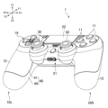
以下、本開示で提案する入力デバイスの例について説明する。図1は入力デバイスの一例を示す斜視図である。以下の説明において、図1に示すY1及びY2はそれぞれ前方及び後方である。また、X1及びX2はそれぞれ右方向及び左方向である。また、Z1及びZ2はそれぞれ上方及び下方である。An example of an input device proposed in this disclosure will now be described. FIG. 1 is a perspective view showing an example of an input device. In the following description, Y1 and Y2 shown in FIG. 1 are respectively forward and backward. X1 and X2 are respectively rightward and leftward. Z1 and Z2 are respectively upward and downward.
入力デバイス1は、ゲームプログラムの実行機能や、動画像再生機能、インターネットを通した通信機能などを有する情報処理装置に対する入力デバイスとして利用される。入力デバイス1は、ユーザが入力デバイス1に対して行った操作に応じた信号を情報処理装置に有線又は無線で送信する。入力デバイス1は、入力デバイス1の姿勢や動きの検出に利用される種々のセンサ(加速度センサ、ジャイロセンサなど)や、バッテリなどを内蔵している。入力デバイス1は、センサの出力も情報処理装置に送信する。The
図1に示す例において、入力デバイス1は、その左部及び右部に、ユーザが左右の手でそれぞれ保持するための左右の被保持部10L・10Rを有している。被保持部10L・10Rの前部の間に中央部21が配置されている。被保持部10L・10Rは、その後部にグリップ12を有している。グリップ12は中央部21の後面よりも後方に伸びている。In the example shown in Figure 1, the
被保持部10L・10Rの前部の上面に、ユーザが操作するための複数の入力部材が設けられている。例えば、右側の被保持部10Rの前部の上面に、複数の操作ボタン11が設けられている。例えば、4つの操作ボタン11が十字の端部に位置している。また、左側の被保持部10Lの前部の上面に、十字形状を有する方向キー19が設けられている。A plurality of input members for user operation are provided on the upper front surface of the held
図1に示すように、入力デバイス1はキャビネット40を有している。キャビネット40は入力デバイス1の外面を構成するとともに、入力デバイス1が備える種々の部品を収容している。この例のキャビネット40は上キャビネット半体41と下キャビネット半体49とを有し、これらは上下方向において互いに組み合わされている。As shown in Figure 1, the
図1に示すように、入力デバイス1は、中央部21の上面に、板状の入力部材22を有している。入力部材22は、その上面に触れた指の位置を検出するためのタッチセンサを含んでいる。また、入力部材22はユーザの押下操作に応じて上下動できるように支持されている。入力デバイス1は、入力部材22が押されたことを検知するスイッチを有しており、入力部材22はオン/オフ操作が可能なボタンとして機能している。As shown in FIG. 1, the
なお、図1で示す例とは異なり、入力デバイス1はユーザが片手で保持するデバイスであってもよい。例えば、入力デバイス1は1本の棒状グリップを有してよい。この場合、入力デバイス1は、上述した左右の被保持部10L・10Rや中央部21を有していなくてよい。Unlike the example shown in FIG. 1, the
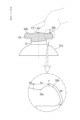
入力デバイス1は、初期位置から半径方向に動かすことのできるタッチ部32を含む入力ユニットを有している。入力ユニットは、左右の入力スティック30を有している。入力スティック30は支柱部31(図2参照)を有し、タッチ部32は支柱部31の最上部に設けられている。ユーザの指はタッチ部32に触れて、入力スティック30を操作する。タッチ部32は円盤状であり、その外径は支柱部31の外径よりも大きい。入力スティック30の高さ(長さ)は、被保持部10R・10Lの上面に設けられた他の入力部材(すなわち、操作ボタン11及び方向キー19)よりも高い。入力スティック30は、例えば、初期位置からその半径方向に傾けたり、傾けた状態で初期位置を中心にして回転させることができる。入力ユニットは、入力スティック30の基部に、入力スティック30を支持する支持機構と、入力スティック30の位置(傾き角度と傾けた方向)とに応じた信号を出力するセンサとを有している。入力スティック30は、支柱部31の下部に支持機構を覆うスカート31aを有している。入力デバイス1は傾きや傾いた
方向に応じた信号を情報処理装置に送信する。
The
なお、入力ユニットを構成する入力部材として、図で示す入力スティック30に替えて、半径方向にスライド可能なタッチ部を有している入力部材が利用されてもよい。In addition, as an input member constituting the input unit, an input member having a radially slidable touch portion may be used instead of the
タッチ部32は、例えばポリカーボネートやABS(acrylonitrile butadiene styrene)などの樹脂で形成される。タッチ部32は2種類の材料で形成されてもよい。例えば、タッチ部32の外面(後述する凹凸のパターンを形成する部分)は、ゴムやエラストマーなど弾性を有する材料で形成され、タッチ部32の内部はポリカーボネートやABSなどの樹脂で形成されてもよい。入力スティック30の位置や材料は、入力デバイス1の例に限られない。例えば、入力スティック30は、被保持部10R・10Lの前部に位置してよい。
The
[タッチ部]
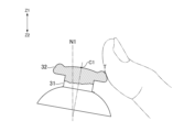
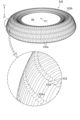
図2Aで示すように、タッチ部32の上面は上方に膨らんでいる外周部32bを有している。外周部32bは、入力デバイス1の平面視において、入力スティック30の上面の中心C1を取り囲む環状である。親指は入力スティック30を倒すとき、外周部32bの頂部Tより内側に規定されている内側領域R1に引っかかり、半径方向の外側に向かう力を入力スティック30に加える。反対に、入力スティック30を初期位置に戻すとき、親指は、図2Bで示すように、外周部32bの頂部Tより外側に規定されている外側領域R2(図2A参照)に当たり、鉛直線N1に向かう力を入力スティック30に加える。
[Touch section]
As shown in Fig. 2A, the upper surface of the
ここで、頂部Tは、例えば、タッチ部32の外周部32bの上面において最も高い位置である。入力スティック30の初期位置とは、例えば、入力スティック30が配置されている面(入力デバイス1においては、中央部21の上面)に対して垂直な姿勢である。鉛直線N1は入力スティック30が初期位置にあるときに、その入力スティック30の支柱部31の中心を通る線である。入力デバイス1は、入力スティック30を初期位置に付勢する機構(例えば、ばね)を有していてもよいし、そのような機構を有していなくてもよい。
Here, the top T is, for example, the highest position on the upper surface of the outer
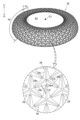
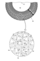
内側領域R1と外側領域R2のいずれの領域も、タッチ部32の上面の中心を取り囲む環状の領域である。図3及び図4で示すように、外側領域R2と内側領域R1のそれぞれに、凹部と凸部の少なくとも一方が規則的に並ぶパターンが形成されてよい。このように、外側領域R2と内側領域R1のそれぞれにパターンが形成されると、親指が入力スティック30を倒すときと、親指が入力スティック30を初期位置に戻すときのいずれにおいても、パターンが滑り止めとして機能し、親指の力が入力スティック30にスムーズに加わる。なお、「凹部と凸部の少なくとも一方が規則的に並ぶ」とは、1つの凸部や1つの凹部であるパターン単位が、内側領域R1において周方向及び半径方向に周期的に繰り返し、外側領域R2において周方向及び軸方向に周期的に繰り返すことを意味する。入力デバイス1の例においては、内側領域R1のパターンは、内側領域R1の全周に亘って形成され、外側領域R2のパターンは、外側領域R2の全周に亘って形成されている。入力デバイス1の例とは異なり、内側領域R1のパターンは、内側領域R1の周方向における一部(例えば、ユーザの指が触れる頻度が特に高い部分)にだけ形成されてよい。同様に、外側領域R2のパターンは、外側領域R2の周方向における一部(例えば、ユーザの指が触れる頻度が特に高い部分)にだけ形成されてもよい。Both the inner region R1 and the outer region R2 are annular regions surrounding the center of the upper surface of the
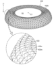
図2Aで示すように、凹凸のパターンが形成されている内側領域R1は、外周部32bの頂部Tに向かって徐々に高くなる斜面を含んでいる。タッチ部32の上面は内側領域R1よりもさらに内側に、凹凸のパターンが形成されていない領域(中央領域R3と称する)を有してもよい。また、入力スティック30の例とは異なり、中央領域R3にも凹凸のパターンが形成されてもよい。中央領域R3は、上面の中心C1の位置が最も高くなるように湾曲している。As shown in FIG. 2A, the inner region R1 in which the uneven pattern is formed includes a slope that gradually becomes higher toward the top T of the
また、図で示す例では、タッチ部32の上面は、外周部32bの内側に凹部32c(図2A参照)を有している。凹凸のパターンが形成されている内側領域R1は、凹部32cにおい最も低い部分よりもさらに内側にも及んでいる。また、凹凸のパターンが形成されている外側領域R2は、タッチ部32の上面だけで無く、タッチ部32の側面にまで及んでいる。In the example shown in the figure, the top surface of the
[パターン]
外側領域R2に形成されているパターンと、内側領域R1に形成されているパターンは相互に異なっているとよい。つまり、外側領域R2と内側領域R1とは、パターンを構成する各凹部又は各凸部において、形状、サイズ、及び姿勢の少なくとも1つが相違しているとよい。(ここでは、各凸部と各凹部の双方をパターン単位と称する。)こうすることによって、入力スティック30を半径方向に倒すという親指の動きに適したパターンと、入力スティック30を初期位置に戻すという親指の動きに適したパターンを、2つの領域R1・R2にそれぞれ形成できる。
[pattern]
The pattern formed in the outer region R2 and the pattern formed in the inner region R1 may be different from each other. In other words, the outer region R2 and the inner region R1 may differ in at least one of the shape, size, and attitude of each concave or convex portion constituting the pattern. (Here, both the convex portion and the concave portion are referred to as a pattern unit.) In this way, a pattern suitable for the thumb movement of tilting the
内側領域R1における適切なパターンは、例えば、親指が入力スティック30を半径方向に倒すときに親指の滑りを防止するのに効果的なパターンである。このようなパターンとして、立ち面(例えば、後述する凸部33の立ち面33n)を有するパターンがある。立ち面は、内側領域R1に形成される凸部の外面の一部、或いは内側領域R1に形成される凹部の内面の一部であり、且つ、内側領域R1の内側に向いている面である。立ち面は、例えば、タッチ部32の表面に沿う面(例えば、凹部32cから外周部32bの頂部Tに向かって徐々に高くなる、図2Aで示す斜面)との間に30度以上の角度を有する。An appropriate pattern in the inner region R1 is, for example, a pattern that is effective in preventing the thumb from slipping when the thumb tilts the
外側領域R2における適切なパターンは、例えば、親指が入力スティック30を初期位置に戻すときに親指の滑りを防止するのに効果的なパターンである。このようなパターンとして、立ち面(例えば、後述する凸部34の立ち面34n)を有するパターンがある。立ち面は、外側領域R2に形成される凸部の外面の一部、或いは外側領域R2に形成される凹部の内面の一部であり、且つ、内側領域R1とは反対側に向いている面である。立ち面は、例えば、タッチ部32の表面に沿う面(例えば、外周部32bの頂部Tから湾曲しながら下がる、図2Aで示す曲面)との間に30度以上の角度を有する。An appropriate pattern in the outer region R2 is, for example, a pattern that is effective in preventing the thumb from slipping when returning the
図4で示すように、内側領域R1に形成されているパターンは複数の凸部33を有している。(以下では凸部33を内側凸部と称する。)各内側凸部33は略Y字形状であり、内側凸部33の中心C2から3方向にそれぞれ伸びている第1部分凸33a、第2部分凸33b、及び第3部分凸33cを有している。各部分凸33a・33b・33cは、図4で示すように、それらの先端に近づくにつれて徐々に細くなっていてよい。図3で示すように、外側領域R2に形成されているパターンは複数の凸部34を有している。(以下では凸部34を外側凸部と称する。)各外側凸部34は略Y字形状であり、外側凸部34の中心C3から3方向にそれぞれ伸びている第1部分凸34a、第2部分凸34b、及び第3部分凸34cを有している。各部分凸34a・34b・34cも、図3で示すように、それらの先端に近づくにつれて徐々に細くなっていてよい。領域R1・R2において、凸部33・34と後述する中間凸部35以外の部分は相対的に凹んでいる。つまり、内側領域R1と外側領域R2のそれぞれに凸部と凹部とを含むパターンが形成されている。As shown in FIG. 4, the pattern formed in the inner region R1 has a plurality of
内側凸部33の第1部分凸33aと第2部分凸33bは、中心C2に対して概ね10時の位置と2時の位置とにそれぞれ形成されている。それに対して、外側凸部34の第1部分凸34aと第2部分凸34bは、中心C3に対して概ね8時の位置と4時の位置とにそれぞれ形成されている。つまり、凸部33・34は概ね同じ形状を有しているものの、それらの姿勢(向き)において相違している。具体的には、外側凸部34の姿勢(向き)と内側凸部33の姿勢(向き)は、鉛直線N1に直交する平面に対して対称である。The first and second
外側領域R2のパターン単位(すなわち、各凸部又は各凹部)と内側領域R1のパターン単位は、パターン単位の向きではなく、パターン単位の形状、及び/又はパターン単位のサイズにおいて相違していてもよい。The pattern units of the outer region R2 (i.e., each convex portion or each concave portion) and the pattern units of the inner region R1 may differ in the shape of the pattern units and/or the size of the pattern units, but not in the orientation of the pattern units.
図4で示すように、内側凸部33において、第1部分凸33aと第2部分凸33bは、内側領域R1の内側に向いている立ち面33nを有している。ここで、「立ち面33nが内側領域R1の内側に向いている」とは、タッチ部32の外面に対して直交する方向にこれを見たときに、立ち面33nの垂線(図4の線L3参照)が半径方向の内側に向かうことを意味する。図で示す例では、立ち面33nの垂線L3は半径方向に対して斜めの方向に向いている。親指は入力スティック30を倒すために内側領域R1にあたるとき、立ち面33nに引っかかる。このことによって、親指の滑りを効果的に抑えることができる。As shown in FIG. 4, in the inner
特に、立ち面33nは、タッチ部32の平面視において、内側領域R1の内側に向かって開いている略V字形状である。つまり、立ち面33nは、立ち面33nの中心33mで屈曲し凹んでいる。このことによって、親指の滑りをさらに効果的に抑えることができる。立ち面33nの形状はこれに限られない。立ち面33nは内側領域R1の内側に向かって開いている略U字形状であってもよい。また、立ち面33nの角度(立ち面33nが形成されているタッチ部32の上面に対する角度)は、親指が引っかかる角度であれば、上面に対して垂直であってもよいし、上面に対して斜めであってもよい。In particular, the standing
内側凸部33は、立ち面33n(言い換えれば、部分凸33a・33b)から半径方向の外方に伸びている第3部分凸33cを有している。このことによって、親指が入力スティック30を半径方向に倒すために内側領域R1にあたるとき、内側凸部33の変形を抑えることができる。The
内側凸部33のこのような形状によって、内側領域R1に沿って半径方向の外側に動こうとする親指に対する摩擦が、反対方向に動こうとする親指に対する摩擦より大きくなる。This shape of the inner
なお、内側領域R1には、パターン単位として凹部が形成されてもよい。この場合、凹部の内面の一部が、親指が引っかかる立ち面として機能し得る。In addition, recesses may be formed as pattern units in the inner region R1. In this case, a portion of the inner surface of the recess may function as a standing surface on which the thumb can be hooked.
図3で示すように、外側凸部34において、第1部分凸34aと第2部分凸34bは、内側領域R1とは反対側に向いている立ち面34nを有している。ここで、「立ち面34nが内側領域R1とは反対側に向いている」とは、タッチ部32の外面に対して直交する方向にこれを見たときに、立ち面34nの垂線(図3の線L4参照)が下側又は半径方向の外側に向いていることを意味する。図で示す例では、立ち面34nの垂線L4は斜め下側に向いている。親指は入力スティック30を初期位置に戻すとき、外側領域R2にあたり、立ち面34nに引っかかる。このことによって、親指の滑りを効果的に抑えることができる。
As shown in Fig. 3, in the outer
特に、立ち面34nは、内側領域R1とは反対側に向かって開いている略V字形状である。つまり、立ち面34nは、立ち面34nの中心34mで屈曲し、凹んでいる。このことによって、親指の滑りをさらに効果的に抑えることができる。立ち面34nの形状はこれに限られない。立ち面34nはタッチ部32の中心C1とは下側又は半径方向の外側に向かって開いている略U字形状であってもよい。また、立ち面34nの角度(立ち面34nが形成されているタッチ部32の上面或いは側面に対する角度)は、親指が引っかかる角度であれば、これらの面に対して垂直であってもよいし、これらの面に対して斜めであってもよい。In particular, the standing
外側凸部34は、立ち面34n(言い換えれば、部分凸34a・34b)から中心C1に向かって伸びている第3部分凸34cを有している。このことによって、親指が入力スティック30を初期位置に戻すために外側領域R2にあたるとき、外側凸部34の変形を抑えることができる。The outer
外側凸部34のこのような形状によって、外側領域R2に沿ってタッチ部32の中心C1に向かって動こうとする親指に対する摩擦が、反対方向に向かって動こうとする親指に対する摩擦より大きくなる。Due to this shape of the outer
なお、外側領域R2には、パターン単位として凹部が形成されてもよい。この場合、凹部の内面の一部が、親指が引っかかる立ち面として機能し得る。In addition, recesses may be formed as pattern units in the outer region R2. In this case, a portion of the inner surface of the recess may function as a standing surface on which the thumb can rest.
図3で示すように、外側領域R2において、第1部分凸34aの端部は隣の外側凸部34(より具体的には、隣の外側凸部34の第1部分凸34aと第3部分凸34cとの間)に近接している。同様に、第2部分凸34bの端部は隣の外側凸部34に近接し、第3部分凸34cの端部は隣の外側凸部34に近接している。このことによって、外側凸部34の密度が高くなり、親指の滑りを効果的に抑えることができる。3, in the outer region R2, the end of the first partial convex 34a is adjacent to the adjacent outer convex portion 34 (more specifically, between the first partial convex 34a and the third partial convex 34c of the adjacent outer convex portion 34). Similarly, the end of the second partial convex 34b is adjacent to the adjacent outer
また、図4で示すように、内側領域R1において、第1部分凸33aの端部は隣の内側凸部33(より具体的には、隣の内側凸部33の第1部分凸33aと第3部分凸33cとの間)に近接している。同様に、第2部分凸33bの端部は隣の内側凸部33に近接し、第3部分凸33cの端部は隣の内側凸部33に近接している。このことによって、内側凸部33の密度が高くなり、親指の滑りを効果的に抑えることができる。4, in the inner region R1, the end of the first partial convex 33a is adjacent to the adjacent inner convex portion 33 (more specifically, between the first partial convex 33a and the third partial convex 33c of the adjacent inner convex portion 33). Similarly, the end of the second partial convex 33b is adjacent to the adjacent inner
[中間凸部]
図5で示すように、タッチ部32は、内側領域R1と外側領域R2とに跨がる複数の凸部35を有している。(以下では凸部35を中間凸部と称する。)中間凸部35は、内側凸部33が有している立ち面33nに対応する立ち面35n1と、外側凸部34が有している立ち面34nに対応する立ち面35n2とを有している。
[Middle convex part]
5, the
すなわち、立ち面35n1は、内側領域R1の内側に向いている面である。親指が入力スティック30を半径方向に倒すとき、立ち面35n1も親指に引っかかり、親指の滑りを抑えることができる。一方、立ち面35n2は、内側領域R1とは反対側に向いている。親指が入力スティック30を初期位置に戻すとき、立ち面35n2も親指に引っかかり、親指の滑りを抑えることができる。
In other words, the upright surface 35n1 is a surface facing inward of the inner region R1. When the thumb tilts the
中間凸部35は、互いに反対方向に向いている2つの略Y字形状を繋げた形状である。すなわち、中間凸部35は、第1部分凸35a、第2部分凸35b、第3部分凸35c、第4部分凸35d、及び連結凸35eを有している。連結凸35eの一端は第1部分凸35aと第2部分凸35bとの間に接続している。第1部分凸35aと第2部分凸35bは、連結凸35eの一端に対して概ね10時の位置と2時の位置とにそれぞれ形成されている。連結凸35eの他端は第3部分凸35cと第4部分凸35dとの間に接続している。第3部分凸35cと第4部分凸35dは、連結凸35eの他端に対して概ね8時と4時の位置にそれぞれ形成されている。The
複数の中間凸部35はタッチ部32の中心C1を中心とする周方向で並んでいる。隣り合う2つの中間凸部35の位置は、タッチ部32の周方向で重なっている。すなわち、中間凸部35の第1部分凸35aと第3部分凸35cのうちの一方の部分凸は、隣の中間凸部35の第2部分凸35bと第4部分凸35dとの間に位置している。同様に、中間凸部35の第2部分凸35bと第4部分凸35dのうちの一方の部分凸は、反対隣の中間凸部35の第1部分凸35aと第3部分凸35cとの間に位置している。このことによって、中間凸部35の密度が高くなり、親指の滑りをさらに効果的に抑えることができる。
The multiple intermediate
[変形例]
本開示で提案する入力スティックは、これまで説明した入力スティック30に限られない。図6乃至図10は、本開示で提案する入力スティックの他の例を示す図である。
[Modification]
The input stick proposed in this disclosure is not limited to the above-described
図6乃至図10は、本開示で提案する入力スティックのタッチ部の例として、タッチ部132~532をそれぞれ示している。タッチ部132~532の上面は、タッチ部32と同様に、上方に膨らんでいる外周部132b~532bをそれぞれ有している。また、タッチ部132~532の外面は、タッチ部32と同様に、外周部132b~532bの頂部Tより内側に規定されている内側領域R1(図2A参照)と、頂部Tより外側に規定されている外側領域R2(図2A参照)とを有している。タッチ部132~532は、内側領域R1と外側領域R2の双方において共通の凹凸パターンを有している。
Figures 6 to 10
図6は、本開示で提案する入力スティックのタッチ部の変形例として、タッチ部132を示している。タッチ部132は複数の凸部133a・133bを有している。各凸部133a・133bは三角形であり、6つの凸部133a・133bが、全体として6角形となる1つの組を構成している。各凸部133a・133bは内側領域R1の内側に向いて斜めに立ち面133nを有している。また、各凸部133a・133bは内側領域R1とは反対側に向いて斜めに形成されている立ち面133mを有している。親指は、入力スティック30を半径方向に倒すとき、内側領域R1にあたり、内側領域R1に形成されている凸部133a・133bの立ち面133nに引っかかる。また、親指は、入力スティック30を初期位置に戻すとき、外側領域R2にあたり、外側領域R2に形成されている凸部133a・133bの立ち面133mに引っかかる。
Figure 6 shows
図7は、本開示で提案する入力スティックのタッチ部の変形例として、タッチ部232を示している。タッチ部232は複数の凸部233を有している。各凸部233は六角形であり、内側領域R1の内側に向いている立ち面233nを有している。また、各凸部233は内側領域R1とは反対側に向いている立ち面233mを有している。親指は、入力スティック30を半径方向に倒すとき、内側領域R1にあたり、内側領域R1に形成されている凸部233の立ち面233nに引っかかる。また、親指は、入力スティック30を初期位置に戻すとき、外側領域R2にあたり、外側領域R2に形成されている凸部233の立ち面233mに引っかかる。
Figure 7 shows a
図8は、本開示で提案する入力スティックのタッチ部の変形例として、タッチ部332を示している。タッチ部332は複数の凸部333a・333bを有している。各凸部333a・333bは直角三角形である。凸部333aは、内側領域R1の内側に向いている立ち面333nを有している。凸部333bは、内側領域R1とは反対側に向いている立ち面333mを有している。親指は、入力スティック30を半径方向に倒すとき、内側領域R1にあたり、内側領域R1に形成されている凸部333aの立ち面333nに引っかかる。また、親指は、入力スティック30を初期位置に戻すとき、外側領域R2にあたり、外側領域R2に形成されている凸部333bの立ち面333mに引っかかる。
Figure 8 shows
図9は、本開示で提案する入力スティックのタッチ部の変形例として、タッチ部432を示している。タッチ部432は複数の凸部433を有している。各凸部433は、タッチ部432の外面に対して直交する方向で見たときに、四角形である。各凸部433は四角錐であり、斜面433nと斜面433mを有している。親指は、入力スティック30を半径方向に倒すとき、内側領域R1にあたり、内側領域R1に形成されている凸部433の斜面433nに引っかかる。また、親指は、入力スティック30を初期位置に戻すとき、外側領域R2にあたり、外側領域R2に形成されている凸部433の斜面433mに引っかかる。
Figure 9 shows
図10は、本開示で提案する入力スティックのタッチ部の変形例として、タッチ部532を示している。タッチ部532は複数の凸部533を有している。各凸部533は、タッチ部532の外面に対して直交する方向で見たときに、細長い四角形である。凸部533は、内側領域R1の内側に向いている立ち面533nと、内側領域R1とは反対側に向いている立ち面533mを有している。親指は、入力スティック30を半径方向に倒すとき、内側領域R1にあたり、内側領域R1に形成されている凸部533の立ち面533nに引っかかる。また、親指は、入力スティック30を初期位置に戻すとき、外側領域R2にあたり、外側領域R2に形成されている凸部533の立ち面533mに引っかかる。複数の凸部533が、タッチ部532の中心C1から半径方向に外側に向かって伸びている列を形成している。隣り合う2つの列の間に溝533eが形成されている。
FIG. 10 shows a
[まとめ]
以上説明したように、入力スティック30は、その最上部に、ユーザの指が触るタッチ部32・132~532を有している。タッチ部32・132~532の上面は、上方に膨らんでいる外周部32b・132b~532bを有している。タッチ部32・132~532は、外周部の頂部Tより外側の領域であり凹部又は凸部の少なくとも一方が規則的に並ぶパターンが形成されている外側領域R2と、外周部の頂部Tの内側の領域であり凹部又は凸部の少なくとも一方が規則的に並ぶパターンが形成されている内側領域R1とを有している。この構造によると、親指は入力スティック30を半径方向に倒すとき、内側領域R1にあたり内側領域R1のパターンに引っかかる。また、親指は入力スティック30を初期位置に戻すとき、外側領域R2にあたり外側領域R2のパターンに引っかかる。このことによって、入力スティック30を半径方向に倒すときと、入力スティック30を初期位置に戻すときのいずれにおいても、親指の力が入力スティック30にスムーズに加えられる。
[summary]
As described above, the
また、タッチ部32は、その外周部に規定され凹部又は凸部の少なくとも一方が並ぶパターンが形成されている外側領域R2と、外側領域R2の内側に規定され凹部又は凸部の少なくとも一方が並ぶパターンが形成されている内側領域R1とを有している。内側領域R1のパターンと外側領域R2のパターンは異なっている。こうすることによって、入力スティック30を半径方向に倒すという親指の動きに適したパターン(すなわち親指が入力スティック30を倒すときに親指の滑りを防止するのに効果的なパターン)と、入力スティック30を初期位置に戻すという親指の動きに適したパターン(すなわち親指が入力スティック30を初期位置に戻すときに親指の滑りを防止するのに効果的なパターン)を、2つの領域R1・R2にそれぞれ形成できる。なお、この構造は、外周部32bが上方に膨らんでいないタッチ部に適用されてもよい。
The
以上説明したタッチ部32・132~532の構造は、入力スティック30に替えて、半径方向にスライド可能な入力部材に適用されてもよい。半径方向にスライド可能な入力部としては、360度の全方位にスライド可能な入力部材だけでなく、直交する2方向(十字方向)にスライド可能な入力部材などに適用されてよい。さらに他の例では、内側領域R1の周方向における一部、及び/又は外側領域R2の周方向における一部にだけ、上述したパターンが形成されてもよい。The structure of the
[カバー]
また、内側領域R1と外側領域R2とに形成されている凹凸のパターンは、入力デバイス自体ではなく、入力ユニットのタッチ部に脱着可能なカバーに適用されてもよい。図11はこのようなカバーの例としてカバー100を示している。
[cover]
The concave and convex patterns formed in the inner region R1 and the outer region R2 may be applied to a cover that is detachable from the touch part of the input unit, rather than to the input device itself. Fig. 11 shows a cover 100 as an example of such a cover.
カバー100は、入力スティック90のタッチ部92を覆うように形成されている。カバー100は、ゴムやエラストマーなどの柔軟性がある材料で形成されている。タッチ部92の外周面に沿って下がる側部101を有し、側部101の縁101aはタッチ部92の下面に引っかけることができる。ユーザは、側部101を広げることでカバー100をタッチ部92から取り外すことできる。The cover 100 is formed to cover the
カバー100の上面の外周部102は、上方に膨らんでいる。カバー100は、外周部102の頂部Tより外側に規定され凹部及び凸部の少なくとも一方が規則的に並ぶパターンが形成されている外側領域R2と、外周部102の頂部Tより内側に規定され凹部及び凸部の少なくとも一方が規則的に並ぶパターンが形成されている内側領域R1とを有している。領域R1・R2に形成されるパターンは、例えば、図3乃至図5を参照しながら説明したタッチ部32の領域R1・R2に形成されているパターンであってよい。領域R1・R2に形成されるパターンは、図6乃至図10を参照しながら説明したタッチ部132~532の領域R1・R2に形成されているパターンであってもよい。The outer
カバー100のこの構造によると、親指は入力スティック90を半径方向に倒すとき、内側領域R1にあたり内側領域R1のパターンに引っかかる。また、親指は入力スティック90を初期位置に戻すとき、外側領域R2にあたり外側領域R2のパターンに引っかかる。このことによって、入力スティック90を半径方向に倒すときと、入力スティック90を初期位置に戻すときのいずれにおいても、ユーザの指の力が入力スティック90にスムーズに加えられる。
According to this structure of the cover 100, when the
また、カバー100において、領域R1・R2に形成されるパターンは、例えば、図3乃至図5を参照しながら説明したタッチ部32と同様に、互いに異なっていてよい。すなわち、カバー100の外側領域R2と内側領域R1は、パターンを構成する各凹部又は各凸部(パターン単位)の形状、サイズ、及び姿勢の少なくとも1つにおいて相違しているとよい。こうすることによって、入力スティック90を半径方向に倒すという親指の動きに適したパターン(すなわち、親指が入力スティック90を半径方向に倒すときに親指とカバー100との間の滑りを防止するのに効果的なパターン)と、入力スティック90を初期位置に戻すという親指の動きに適したパターン(親指が入力スティック90を初期位置に戻すときに親指とカバー100との滑りを防止するのに効果的なパターン)を、2つの領域R1・R2にそれぞれ形成できる。なお、この構造は外周部102が上方に膨らんでいないカバーに適用されてもよい。
In addition, in the cover 100, the patterns formed in the regions R1 and R2 may be different from each other, for example, as in the
また、以上説明したカバー100の構造は、入力スティック90に脱着可能なカバーではなく、半径方向にスライド可能な入力部材に脱着可能なカバーに適用されてもよい。この場合、カバー100の構造は、360度の全方位にスライド可能な入力部材に脱着可能なカバーだけでなく、直交する2方向(十字方向)にスライド可能な入力部材に脱着可能なカバーに適用されてよい。さらに他の例では、内側領域R1の周方向における一部、及び/又は外側領域R2の周方向における一部にだけ上述したパターンが形成されてもよい。
Furthermore, the structure of the cover 100 described above may be applied to a cover that is detachable from an input member that is slidable in a radial direction, rather than a cover that is detachable from the
Claims (9)
前記外周部の頂部より外側の領域であり、凹部と凸部の少なくとも一方が規則的に並ぶパターンが形成されている外側領域と、
前記外周部の頂部の内側の領域であり、凹部と凸部の少なくとも一方が規則的に並ぶパターンが形成されている内側領域と
を有しており、
前記内側領域に形成されているパターンは、前記タッチ部の平面視において前記内側領域の内側に向いている複数の立ち面を有し、
前記外側領域に形成されているパターンは、前記内側領域とは反対側に向いている複数の立ち面を有している
入力ユニット。 a touch portion having an upper surface with an upwardly expanding outer periphery and movable in a radial direction from an initial position;
an outer region that is an area outside the apex of the outer periphery and in which a pattern in which at least one of recesses and protrusions is regularly arranged is formed;
an inner region that is an inner region of the apex of the outer periphery, in which a pattern in which at least one of recesses and protrusions is regularly arranged is formed;
the pattern formed in the inner region has a plurality of standing surfaces facing inward of the inner region in a plan view of the touch portion,
An input unit, wherein the pattern formed in the outer area has a plurality of elevations facing in the opposite direction to the inner area.
請求項1に記載される入力ユニット。 The input unit according to claim 1 , wherein the pattern formed in the outer region and the pattern formed in the inner region are different.
請求項1に記載される入力ユニット。 The input unit according to claim 1 , wherein each of the plurality of standing surfaces formed in the inner area has a substantially V-shape that opens toward the inside of the inner area or a substantially U-shape that opens toward the inside of the inner area.
請求項1に記載される入力ユニット。 2. The input unit according to claim 1, wherein each of the plurality of vertical surfaces formed in the outer region is approximately V-shaped and opens toward the opposite side of the vertical surface in the inner region, or approximately U-shaped and opens toward the opposite side of the vertical surface in the inner region.
前記タッチ部の外周部に規定され、凹部と凸部の少なくとも一方が並んでいるパターンが形成されている外側領域と、
前記タッチ部の上面において前記外側領域の内側に規定され、凹部と凸部の少なくとも一方が並んでいるパターンが形成されている内側領域とを有し、
前記内側領域のパターンと前記外側領域のパターンは異なっており、
前記外側領域に形成されているパターンは、前記内側領域とは反対側に向いている複数の立ち面を有している
入力ユニット。 a touch portion that can be moved in a radial direction from an initial position;
an outer region defined on the outer periphery of the touch section, in which a pattern in which at least one of concave portions and convex portions is arranged is formed;
an inner region defined inside the outer region on the upper surface of the touch portion, the inner region having a pattern in which at least one of concave portions and convex portions is arranged;
the pattern in the inner region and the pattern in the outer region are different;
An input unit, wherein the pattern formed in the outer area has a plurality of elevations facing in the opposite direction to the inner area.
請求項5に記載される入力ユニット。 The input unit according to claim 5 , wherein the pattern formed in the inner region has a plurality of standing surfaces facing inwardly of the inner region in a plan view of the touch portion.
上方に膨らんでいる外周部を有している上面と、
前記外周部の頂部より外側の領域であり、凹部と凸部の少なくとも一方が規則的に並んでいるパターンが形成されている外側領域と、
前記外周部の頂部の内側の領域であり、凹部と凸部の少なくとも一方が規則的に並んでいるパターンが形成されている内側領域と
を有しており、
前記内側領域に形成されているパターンは、前記上面の平面視において前記内側領域の内側に向いている複数の立ち面を有し、
前記外側領域に形成されているパターンは、前記内側領域とは反対側に向いている複数の立ち面を有している
カバー。 A cover that is detachable from the input unit,
a top surface having an upwardly bulging periphery;
an outer region that is an area outside the apex of the outer periphery and in which a pattern in which at least one of recesses and protrusions is regularly arranged is formed;
an inner region that is an inner region of the apex of the outer periphery, in which a pattern in which at least one of recesses and protrusions is regularly arranged is formed;
the pattern formed in the inner region has a plurality of standing surfaces facing inwardly of the inner region in a plan view of the upper surface ,
The pattern formed in the outer region has a plurality of upright surfaces facing away from the inner region.
前記カバーの外周部に規定され、凹部と凸部の少なくとも一方が並んでいるパターンが形成されている外側領域と、
前記外側領域の内側に規定され、凹部と凸部の少なくとも一方が並んでいるパターンが形成されている内側領域と
を有し、
前記内側領域のパターンと前記外側領域のパターンは異なっており、
前記外側領域に形成されているパターンは、前記内側領域とは反対側に向いている複数の立ち面を有している
カバー。 A cover that is detachable from the input unit,
an outer region defined in an outer periphery of the cover, the outer region having a pattern in which at least one of recesses and protrusions is arranged;
an inner region defined inside the outer region and having a pattern in which at least one of concave portions and convex portions is arranged;
the pattern in the inner region and the pattern in the outer region are different;
The pattern formed in the outer region has a plurality of upright surfaces facing away from the inner region.
Applications Claiming Priority (3)
| Application Number | Priority Date | Filing Date | Title |
|---|---|---|---|
| JP2020046866 | 2020-03-17 | ||
| JP2020046866 | 2020-03-17 | ||
| PCT/JP2021/010426 WO2021187436A1 (en) | 2020-03-17 | 2021-03-15 | Input unit, input device, and cover mountable to input unit |
Publications (3)
| Publication Number | Publication Date |
|---|---|
| JPWO2021187436A1 JPWO2021187436A1 (en) | 2021-09-23 |
| JPWO2021187436A5 JPWO2021187436A5 (en) | 2022-11-09 |
| JP7581327B2 true JP7581327B2 (en) | 2024-11-12 |
Family
ID=77770870
Family Applications (1)
| Application Number | Title | Priority Date | Filing Date |
|---|---|---|---|
| JP2022508355A Active JP7581327B2 (en) | 2020-03-17 | 2021-03-15 | Input unit, input device, and a cover that can be attached to the input unit |
Country Status (5)
| Country | Link |
|---|---|
| US (1) | US20230127210A1 (en) |
| EP (1) | EP4122567A4 (en) |
| JP (1) | JP7581327B2 (en) |
| CN (1) | CN115004135A (en) |
| WO (1) | WO2021187436A1 (en) |
Families Citing this family (1)
| Publication number | Priority date | Publication date | Assignee | Title |
|---|---|---|---|---|
| JP7695701B2 (en) * | 2022-05-06 | 2025-06-19 | 株式会社キーズファクトリー | Stopper and cover |
Citations (2)
| Publication number | Priority date | Publication date | Assignee | Title |
|---|---|---|---|---|
| JP2011143216A (en) | 2010-01-15 | 2011-07-28 | Shin Nakada | Cover for game controller stick |
| JP2016123469A (en) | 2014-12-26 | 2016-07-11 | 株式会社ホリ | controller |
Family Cites Families (11)
| Publication number | Priority date | Publication date | Assignee | Title |
|---|---|---|---|---|
| JPS5544485Y2 (en) * | 1978-07-13 | 1980-10-20 | ||
| JP4408754B2 (en) * | 2004-06-18 | 2010-02-03 | 株式会社クボタ | Riding work machine |
| AU2011310580C1 (en) * | 2010-10-01 | 2016-03-10 | Bracco Imaging Spa | Finger-grip device for medical syringe or cartridge |
| US9713768B2 (en) * | 2012-09-26 | 2017-07-25 | Razer (Asia-Pacific) Pte. Ltd. | Game controller |
| US9789395B2 (en) | 2012-10-15 | 2017-10-17 | Sony Interactive Entertainment Inc. | Operating device |
| JP6414794B2 (en) * | 2014-11-28 | 2018-10-31 | エスゼット ディージェイアイ テクノロジー カンパニー リミテッドSz Dji Technology Co.,Ltd | Dial structure and remote controller using this dial structure |
| US9925457B2 (en) * | 2015-06-09 | 2018-03-27 | Microsoft Technology Licensing, Llc | User-replaceable thumbstick top for game controller |
| US9868058B2 (en) * | 2015-06-30 | 2018-01-16 | Microsoft Technology Licensing, Llc | Thumbstick with adjustable tension |
| EP3272402B1 (en) * | 2016-06-10 | 2019-02-27 | Nintendo Co., Ltd. | Game controller |
| US10561935B2 (en) * | 2017-01-17 | 2020-02-18 | Microsoft Technology Licensing, Llc | Thumbstick for user input device |
| FR3087664B1 (en) * | 2018-10-25 | 2021-09-10 | Bigben Interactive | GAME CONTROLLER INCLUDING AT LEAST ONE REMOVABLE ADJUSTING ELEMENT ALLOWING THE ADJUSTMENT OF THE STOP ANGLE OF A SWIVELING CONTROLLER OF THE CONTROLLER |
-
2021
- 2021-03-15 JP JP2022508355A patent/JP7581327B2/en active Active
- 2021-03-15 WO PCT/JP2021/010426 patent/WO2021187436A1/en not_active Ceased
- 2021-03-15 CN CN202180010888.5A patent/CN115004135A/en active Pending
- 2021-03-15 US US17/909,457 patent/US20230127210A1/en active Pending
- 2021-03-15 EP EP21771989.7A patent/EP4122567A4/en active Pending
Patent Citations (2)
| Publication number | Priority date | Publication date | Assignee | Title |
|---|---|---|---|---|
| JP2011143216A (en) | 2010-01-15 | 2011-07-28 | Shin Nakada | Cover for game controller stick |
| JP2016123469A (en) | 2014-12-26 | 2016-07-11 | 株式会社ホリ | controller |
Non-Patent Citations (3)
| Title |
|---|
| Hotline Games 2.0 PLUS Mouse Grip Tape,日本,amazon [オンライン],2017年08月16日,[検索日 2024.02.22] インターネット:<https://www.amazon.co.jp/Hotline-Games-Anti-Slip-Gaming-Pre-Cut/dp/B08ML7W29F/?th=1>,滑り止めグリップテープの画像 |
| Yossy,ビット・トレード・ワンから独自仕様のマウスソール「HyperMouseSkater」、ゲーミングマウスの操作性を高めるグリップシール「Grips for Gaming」が登場,日本,Negitaku.org,2019年06月08日,[検索日 2024.02.22] インターネット:<https://www.negitaku.org/news/n-23414>,マウスグリップシールの画像 |
| 岩泉茂,お気に入りの1台を見つけよう! ゲームコントローラー特集2019,GAME Watch,日本,Impress Corporation [オンライン],2019年12月18日,[検索日 2023.10.10] インターネット:<URL:https://game.watch.impress.co.jp/docs/feature/1223432.html>,各種ゲームコントローラの画像におけるアナログスティックの形状 |
Also Published As
| Publication number | Publication date |
|---|---|
| EP4122567A4 (en) | 2024-05-01 |
| CN115004135A (en) | 2022-09-02 |
| EP4122567A1 (en) | 2023-01-25 |
| WO2021187436A1 (en) | 2021-09-23 |
| US20230127210A1 (en) | 2023-04-27 |
| JPWO2021187436A1 (en) | 2021-09-23 |
Similar Documents
| Publication | Publication Date | Title |
|---|---|---|
| US7167159B2 (en) | Joystick cover | |
| US4573682A (en) | Joy stick holder | |
| US9908041B2 (en) | Game controller with removable faceted fingerpad | |
| CN112587906B (en) | Glove, in particular goalkeeper glove | |
| US20180207523A1 (en) | Game Controller | |
| TWI576725B (en) | Joystick module | |
| US20180178117A1 (en) | Game controller with removable faceted finger pad | |
| JP7581327B2 (en) | Input unit, input device, and a cover that can be attached to the input unit | |
| WO2018236966A1 (en) | PORTABLE CONTROL DEVICE HAVING REAR HULL AND UNDERLYUCING SENSITIVE STRENGTH RESISTORS | |
| WO2017067387A1 (en) | Handle type gesture recognition device | |
| US8803803B2 (en) | Operation member provided in electronic device, and electronic device | |
| EP1191418A1 (en) | Control device | |
| TWM633344U (en) | Roller | |
| WO2000058819A1 (en) | An actuator device for a personal computer | |
| JPWO2021187436A5 (en) | ||
| JP3196915U (en) | Handle and umbrella | |
| JP6837041B2 (en) | Hemispherical mouse. | |
| WO1999042919A1 (en) | Cursor control device with control stick and hand support | |
| JP7645014B1 (en) | Finger strength training device | |
| JP2004029865A (en) | Mouse | |
| JP2008511939A (en) | Computer mouse | |
| KR100759486B1 (en) | Mouse with fast horizontal movement of cursor | |
| JP6526762B2 (en) | Cleaning tool | |
| KR200398826Y1 (en) | A support apparatus for user's wrist using a mouse | |
| KR200279240Y1 (en) | Joy-stick for game machine |
Legal Events
| Date | Code | Title | Description |
|---|---|---|---|
| A521 | Request for written amendment filed |
Free format text: JAPANESE INTERMEDIATE CODE: A523 Effective date: 20220906 |
|
| A621 | Written request for application examination |
Free format text: JAPANESE INTERMEDIATE CODE: A621 Effective date: 20220906 |
|
| A131 | Notification of reasons for refusal |
Free format text: JAPANESE INTERMEDIATE CODE: A131 Effective date: 20231017 |
|
| A131 | Notification of reasons for refusal |
Free format text: JAPANESE INTERMEDIATE CODE: A131 Effective date: 20240227 |
|
| A601 | Written request for extension of time |
Free format text: JAPANESE INTERMEDIATE CODE: A601 Effective date: 20240430 |
|
| A521 | Request for written amendment filed |
Free format text: JAPANESE INTERMEDIATE CODE: A523 Effective date: 20240524 |
|
| A131 | Notification of reasons for refusal |
Free format text: JAPANESE INTERMEDIATE CODE: A131 Effective date: 20240709 |
|
| A521 | Request for written amendment filed |
Free format text: JAPANESE INTERMEDIATE CODE: A523 Effective date: 20240906 |
|
| TRDD | Decision of grant or rejection written | ||
| A01 | Written decision to grant a patent or to grant a registration (utility model) |
Free format text: JAPANESE INTERMEDIATE CODE: A01 Effective date: 20241001 |
|
| A61 | First payment of annual fees (during grant procedure) |
Free format text: JAPANESE INTERMEDIATE CODE: A61 Effective date: 20241030 |
|
| R150 | Certificate of patent or registration of utility model |
Ref document number: 7581327 Country of ref document: JP Free format text: JAPANESE INTERMEDIATE CODE: R150 |