JP7581324B2 - Welding unit for welding track rails together - Google Patents
Welding unit for welding track rails together Download PDFInfo
- Publication number
- JP7581324B2 JP7581324B2 JP2022506154A JP2022506154A JP7581324B2 JP 7581324 B2 JP7581324 B2 JP 7581324B2 JP 2022506154 A JP2022506154 A JP 2022506154A JP 2022506154 A JP2022506154 A JP 2022506154A JP 7581324 B2 JP7581324 B2 JP 7581324B2
- Authority
- JP
- Japan
- Prior art keywords
- unit
- clamping
- unit part
- rail
- slide
- Prior art date
- Legal status (The legal status is an assumption and is not a legal conclusion. Google has not performed a legal analysis and makes no representation as to the accuracy of the status listed.)
- Active
Links
Images

Classifications
-
- B—PERFORMING OPERATIONS; TRANSPORTING
- B23—MACHINE TOOLS; METAL-WORKING NOT OTHERWISE PROVIDED FOR
- B23K—SOLDERING OR UNSOLDERING; WELDING; CLADDING OR PLATING BY SOLDERING OR WELDING; CUTTING BY APPLYING HEAT LOCALLY, e.g. FLAME CUTTING; WORKING BY LASER BEAM
- B23K11/00—Resistance welding; Severing by resistance heating
- B23K11/04—Flash butt welding
- B23K11/046—Apparatus therefor
-
- B—PERFORMING OPERATIONS; TRANSPORTING
- B23—MACHINE TOOLS; METAL-WORKING NOT OTHERWISE PROVIDED FOR
- B23K—SOLDERING OR UNSOLDERING; WELDING; CLADDING OR PLATING BY SOLDERING OR WELDING; CUTTING BY APPLYING HEAT LOCALLY, e.g. FLAME CUTTING; WORKING BY LASER BEAM
- B23K37/00—Auxiliary devices or processes, not specially adapted for a procedure covered by only one of the other main groups of this subclass
- B23K37/02—Carriages for supporting the welding or cutting element
- B23K37/0211—Carriages for supporting the welding or cutting element travelling on a guide member, e.g. rail, track
- B23K37/0217—Carriages for supporting the welding or cutting element travelling on a guide member, e.g. rail, track the guide member being fixed to the workpiece
-
- B—PERFORMING OPERATIONS; TRANSPORTING
- B23—MACHINE TOOLS; METAL-WORKING NOT OTHERWISE PROVIDED FOR
- B23K—SOLDERING OR UNSOLDERING; WELDING; CLADDING OR PLATING BY SOLDERING OR WELDING; CUTTING BY APPLYING HEAT LOCALLY, e.g. FLAME CUTTING; WORKING BY LASER BEAM
- B23K37/00—Auxiliary devices or processes, not specially adapted for a procedure covered by only one of the other main groups of this subclass
- B23K37/02—Carriages for supporting the welding or cutting element
- B23K37/0282—Carriages forming part of a welding unit
-
- E—FIXED CONSTRUCTIONS
- E01—CONSTRUCTION OF ROADS, RAILWAYS, OR BRIDGES
- E01B—PERMANENT WAY; PERMANENT-WAY TOOLS; MACHINES FOR MAKING RAILWAYS OF ALL KINDS
- E01B11/00—Rail joints
- E01B11/44—Non-dismountable rail joints; Welded joints
- E01B11/46—General methods for making gapless tracks
-
- E—FIXED CONSTRUCTIONS
- E01—CONSTRUCTION OF ROADS, RAILWAYS, OR BRIDGES
- E01B—PERMANENT WAY; PERMANENT-WAY TOOLS; MACHINES FOR MAKING RAILWAYS OF ALL KINDS
- E01B29/00—Laying, rebuilding, or taking-up tracks; Tools or machines therefor
- E01B29/42—Undetachably joining or fastening track components in or on the track, e.g. by welding, by gluing; Pre-assembling track components by gluing; Sealing joints with filling components
- E01B29/46—Devices for holding, positioning, or urging together the rail ends
-
- B—PERFORMING OPERATIONS; TRANSPORTING
- B23—MACHINE TOOLS; METAL-WORKING NOT OTHERWISE PROVIDED FOR
- B23K—SOLDERING OR UNSOLDERING; WELDING; CLADDING OR PLATING BY SOLDERING OR WELDING; CUTTING BY APPLYING HEAT LOCALLY, e.g. FLAME CUTTING; WORKING BY LASER BEAM
- B23K2101/00—Articles made by soldering, welding or cutting
- B23K2101/26—Railway- or like rails
Landscapes
- Engineering & Computer Science (AREA)
- Mechanical Engineering (AREA)
- Architecture (AREA)
- Civil Engineering (AREA)
- Structural Engineering (AREA)
- Physics & Mathematics (AREA)
- Optics & Photonics (AREA)
- Machines For Laying And Maintaining Railways (AREA)
- Butt Welding And Welding Of Specific Article (AREA)
Description
本発明は、軌道のレール同士を溶接するための溶接ユニットであって、第1のユニット部分を備えており、この第1のユニット部分は、ユニットガイドに沿って第2のユニット部分に対して複数のスライドシリンダを用いてレール長手方向に摺動可能であり、各々のユニット部分は、ユニットガイドの下側に、レールをクランプするための、クランプジョーに連結された複数のクランプシリンダを備えている、溶接ユニットに関する。 The present invention relates to a welding unit for welding track rails together, comprising a first unit part, which is slidable in the longitudinal direction of the rail relative to a second unit part along a unit guide using a plurality of slide cylinders, and each unit part is provided below the unit guide with a plurality of clamp cylinders connected to clamp jaws for clamping the rail.
レール同士を溶接するための公知の溶接ユニットは、2つのユニット部分を有しており、一方のユニット部分は、ユニットガイドに沿ってスライドシリンダを用いてレール長手方向に他方のユニット部分に対して摺動可能である。各々のユニット部分は、溶接すべきレールのレール端部を不動にクランプするためのクランプ装置を備えている。溶接工程時に両ユニット部分およびユニット部分において不動にクランプされた両レール端部は、互いに接近移動させることができる。冒頭に述べた形態の溶接ユニットは、中性温度を下回る温度における最終溶接のためにも使用される。このとき、レール端部には、大きな引張り力が加えられなければならない。したがって、ユニットガイド、スライドシリンダおよびクランプ装置に対して、かなり高い要求が課される。 Known welding units for welding rails together have two unit parts, one of which can be slid relative to the other unit part in the rail longitudinal direction by means of a slide cylinder along a unit guide. Each unit part is equipped with a clamping device for immovably clamping the rail end of the rail to be welded. During the welding process, both unit parts and the rail ends immovably clamped in the unit parts can be moved toward each other. The welding unit of the type mentioned at the beginning is also used for final welding at temperatures below the neutral temperature. In this case, high tensile forces must be applied to the rail ends. Therefore, rather high demands are placed on the unit guides, slide cylinders and clamping devices.
オーストリア国実用新案第006690号明細書、西独国特許出願公開第2801249号明細書および国際公開第2010/119461号には、トング状のユニット部分を備えた構造形態が開示されている。公知の構造形態で各々のユニット部分は、レール長手方向に向けられた回転軸線を中心として旋回可能な2つのトングレバーを備えている。下側のレバーアームには、レール端部を不動にクランプするためのクランプジョーが配置されている。上側のレバーアームは、クランプシリンダに連結されている。クランプシリンダへの液圧供給によって、クランプジョーはレバー機構を介して各々のレール端部をクランプする。スライドシリンダは、溶接すべきレールの両側に配置されている。このとき、スライドシリンダは、付加的に、ユニットガイドとしての、回転軸線に配置されたガイドコラムと一緒に働く。ユニット部分のトング状の構造形態に起因して、クランプシリンダはユニットガイドの上に配置されており、クランプ力は、ガイドコラムにおけるユニット部分の支持を必要とする。 Austrian Utility Model No. 006690, German Patent Application No. 2801249 and WO 2010/119461 disclose constructions with tongue-shaped unit parts. In the known constructions, each unit part has two tongue levers that can be pivoted about a rotation axis oriented in the longitudinal direction of the rail. Clamping jaws for immobile clamping of the rail end are arranged on the lower lever arm. The upper lever arm is connected to a clamping cylinder. By hydraulic supply to the clamping cylinder, the clamping jaws clamp the respective rail end via a lever mechanism. Slide cylinders are arranged on both sides of the rail to be welded. In this case, the slide cylinders additionally act together with a guide column arranged on the rotation axis as a unit guide. Due to the tongue-shaped construction of the unit parts, the clamping cylinders are arranged on the unit guides, and the clamping force requires support of the unit parts on the guide columns.
他の構造形態は、オーストリア国特許出願公開第507243号明細書およびオーストリア国特許出願公開第507560号明細書に基づいて公知である。これらの構造形態では、3つのガイドコラムがユニットガイドとして配置されており、このとき、少なくとも2つのユニットガイドは、端面側の横方向支持体を介して結合されている。各々のユニット部分は、剛性の基体を備えており、この基体はその下側に、クランプすべきレール端部のための空間を有している。クランプジョーが、ユニットガイドの下側に配置されたクランプシリンダに直接連結されている。したがって、クランプシリンダへの作用によって、直接クランプ力が生じ、このとき、基体が反力を受け止める。一方のユニット部分に対する他方のユニット部分のスライドは、引張りロッドと、横方向支持体に支持されているスライドシリンダとを介して行われる。 Other constructional configurations are known from AU 507 243 A1 and AU 507 560 A1. In these constructional configurations, three guide columns are arranged as unit guides, with at least two unit guides being connected via lateral supports on the end faces. Each unit part has a rigid base body, which has a space on its underside for the rail end to be clamped. The clamping jaws are directly connected to a clamping cylinder arranged on the underside of the unit guide. Acting on the clamping cylinder thus generates a direct clamping force, with the base body taking up the reaction force. The sliding of one unit part relative to the other takes place via a tension rod and a sliding cylinder supported on the lateral supports.
本発明の根底にある課題は、冒頭に述べた形態の溶接ユニットを改良して、構造が改善された溶接ユニットを提供することである。 The problem underlying the present invention is to improve the welding unit of the type described at the beginning and provide a welding unit with an improved structure.
本発明によれば、この課題は、請求項1の特徴によって解決される。従属請求項には、本発明の有利な構成が記載されている。 According to the invention, this problem is solved by the features of claim 1. Advantageous configurations of the invention are described in the dependent claims.
本発明では、両方のユニット部分が、スライドシリンダを用いて互いに結合されており、各々のスライドシリンダのシリンダボディが、一方のユニット部分に結合されていて、各々のスライドシリンダのピストンロッドが、他方のユニット部分に結合されている。このように構成されていると、スライドシリンダを端面側の横方向支持体に支持する必要がなくなる。このようにして、スライドシリンダは、クランプシリンダと一緒に、溶接すべきレール端部に長手方向力を伝達するためのユニットを形成する。この場合に重要なのは、ユニットガイドを力伝達装置から機能的に分離することである。ユニットガイドは、両ユニット部分相互のガイド機能を引き受け、クランプシリンダのクランプ機能に関与することはない。ユニットガイドは、引張り力または押圧力から解放されている。 In the present invention, both unit parts are connected to each other by means of slide cylinders, the cylinder body of each slide cylinder being connected to one unit part and the piston rod of each slide cylinder being connected to the other unit part. With this configuration, it is not necessary to support the slide cylinders on the lateral supports on the end faces. In this way, the slide cylinders together with the clamping cylinders form a unit for transmitting longitudinal forces to the rail ends to be welded. What is important in this case is the functional separation of the unit guide from the force transmission device. The unit guide takes over the mutual guiding function of both unit parts and does not participate in the clamping function of the clamping cylinders. The unit guide is free from tensile or compressive forces.
有利な発展形態では、スライドシリンダの長手方向軸線とクランプシリンダの長手方向軸線とが、ほぼ共通の平面に配置されている。これによって、ユニット部分における負荷が減少する。なぜならば、互いに離隔された力軸線に基づく付加的な曲げ応力が発生しないからである。 In an advantageous development, the longitudinal axis of the sliding cylinder and the longitudinal axis of the clamping cylinder are arranged approximately in a common plane. This reduces the load on the unit parts, since no additional bending stresses due to mutually separated force axes occur.
クランプジョーは、溶接すべきレールが、共通の平面に位置している中立軸でもって不動にクランプ可能であるように配置されていると有利である。このような配置形態によって、スライド力が、レールの中立軸を含む平面内で作用するので、ユニット部分およびユニットガイドは、傾倒モーメントを受け止める必要がない。ユニットガイドには、ユニット部分の重量と、溶接工程中に不動にクランプされていて、持ち上げられているレール端部の重量としか作用しない。 Advantageously, the clamping jaws are arranged so that the rails to be welded can be clamped stationary with their neutral axes lying in a common plane. With this arrangement, the unit parts and the unit guides do not have to bear tilting moments, since the sliding forces act in a plane containing the neutral axis of the rails. The unit guides are only subjected to the weight of the unit parts and the weight of the rail ends which are clamped stationary and raised during the welding process.
本発明の発展形態では、各々のユニット部分が、ユニットガイドの下側にクランプボディを備えており、このクランプボディ内に相並んで複数のクランプシリンダが組み込まれていることが特定されている。このように構成されていると、各々のユニット部分のコンパクトな構造形態が得られ、結果として、十分に高い総クランプ力が得られる。 In a further development of the invention, it is specified that each unit part has a clamping body on the underside of the unit guide, in which a number of clamping cylinders are assembled side by side. In this way, a compact construction of each unit part is obtained, which results in a sufficiently high total clamping force.
溶接ユニット全体のコンパクトな構造形態を得るために、有利には、スライドシリンダが、ユニット部分の側方の外面にフランジ結合されている。このように構成されていると、スライドシリンダの配置が、ユニット部分およびクランプシリンダから構造的に分離されている。これによって、溶接ユニットの設計が容易になり、種々様々なスライドシリンダの配置によって、得ることができるスライド力を変化させることができる。結果として、同一構造のユニット部分を異なる出力の溶接ユニットのために使用することができるモジュールシステムが得られる。 In order to obtain a compact construction of the entire welding unit, the sliding cylinders are advantageously flange-connected to the lateral outer surface of the unit part. In this way, the arrangement of the sliding cylinders is structurally separated from the unit part and the clamping cylinder. This makes it easier to design the welding unit and allows the obtainable sliding force to be varied by various arrangements of the sliding cylinders. As a result, a modular system is obtained in which unit parts of the same construction can be used for welding units of different power.
ガイドの構成では、ガイドシステムとして、特に滑り管として形成された3つのユニットガイドが、互いにずらされて配置されていると有利である。このように構成されていると、ガイドシステムの重量と安定性との間の最適な形態を得ることができる。 In the configuration of the guide, it is advantageous if the three unit guides, in particular those formed as sliding tubes, are arranged offset from one another as a guide system. In this way, an optimum can be achieved between the weight and stability of the guide system.
好ましくは、外側の2つのユニットガイドが相並んで配置されていて、真ん中のユニットガイドが上方に向かってずらされて配置されている。このように構成されていると、受け止めるべき力が、可能な限り均等に3つのユニットガイドに分配される。 Preferably, the two outer unit guides are arranged side by side, and the middle unit guide is offset upwards. In this configuration, the forces to be received are distributed as evenly as possible to the three unit guides.
ガイドシステムの安定性は、第1のユニット部分が、第2のユニット部分と横方向結合部材との間に配置されており、ユニットガイドが、一方で第2のユニット部分に不動に結合されていて、他方で横方向結合部材に不動に結合されていると、さらに高められる。横方向結合部材は、単にガイドシステムのコンポーネントであり、スライド力またはクランプ力を伝達しない。 The stability of the guide system is further increased if the first unit part is arranged between the second unit part and the lateral connecting member and the unit guide is fixedly connected on the one hand to the second unit part and on the other hand to the lateral connecting member. The lateral connecting member is merely a component of the guide system and does not transmit sliding or clamping forces.
構造をさらに改善することによって、各々のユニット部分が、同一構造の基体を備えることが特定されている。この有利な構成は、ガイドシステムとスライドシリンダとの分離によって得られる。 By further improving the structure, it has been specified that each unit part has a base body of the same structure. This advantageous configuration is obtained by separating the guide system and the slide cylinder.
各々の基体が、両長辺側に、それぞれ異なる長さのスライドシリンダをフランジ結合するための複数の結合箇所を相並んで有していると有利である。このように構成されていると、スライドシリンダの取付け形態を簡単に変化させることができる。それぞれ異なる出力の溶接ユニットは、スライドシリンダの交換によって実現することができる。 Each base body advantageously has a number of adjacent connection points on both long sides for flange-connecting slide cylinders of different lengths. In this way, the mounting configuration of the slide cylinders can be easily changed. Welding units of different outputs can be realized by replacing the slide cylinders.
次に本発明の実施例を、添付の図面を参照しながら説明する。 Next, an embodiment of the present invention will be described with reference to the attached drawings.
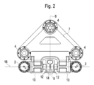
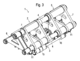
図1~図4に示した溶接ユニット1では、第1のユニット部分2が、スライドシリンダ3を用いてユニットガイド4に沿って第2のユニット部分5に対して摺動可能である。横断面で見て二等辺三角形の各頂点に配置されたユニットガイド4は、端部側で横方向結合部材6に不動に結合されている。横方向結合部材6の反対に位置している側では、ユニットガイド4は第2のユニット部分5に不動に結合されている。両結合部の間には、摺動可能な第1のユニット部分2が配置されている。このようにして、ユニットガイド4は端部側の結合部と共に不動のガイドシステムを形成している。
In the welding unit 1 shown in Figures 1 to 4, the
各々のユニット部分2,5は、例えば溶接構造体として形成された同一構造の基体7を備えている。図示の構成では、ユニットガイド4は、3つの滑り管を備えている。下側の2つの滑り管は、鉛直の対称面8に対して対称に配置されている。上側の滑り管は、それに対して真ん中に配置されているので、この滑り管の長手方向軸線は、対称面8に位置している。第1のユニット部分2の基体7には、滑り管に沿って滑動する滑りブシュが配置されている。第2のユニット部分5の基体7には、滑り管は不動にクランプされている。
Each of the
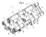
ユニットガイド4の下側では、各々のユニット部分2,5が、空間9の両側に各々のクランプボディ10を含んでいる。各々のクランプボディ10には、3つのインナシリンダが相並んで配置されており、これらのインナシリンダ内で、ピストンロッドを備えたピストンがガイドされている。このようにして、各々のクランプボディ10は、液圧的に連結された3つのクランプシリンダ11を備えており、これらのクランプシリンダ11のピストンロッドは、端部側で1つの共通のクランプジョー12に結合されている。各々のクランプボディ10の外面において、クランプシリンダ11はシリンダカバー13を用いて閉鎖されている。
Below the
クランプボディ10同士の間の空間9内に、互いに溶接すべきレール14が収容され、そこで不動にクランプされる。具体的には、運転中に、クランプシリンダ11に液圧が加えられ、これによって、クランプジョー12が、互いに溶接すべきレール14に押し付けられる。
The
スライドシリンダ3は、両側でユニット部分2,5の側方の外面にフランジ結合されている。各々のスライドシリンダ3のシリンダボディ15は、一方のユニット部分2に結合されていて、ピストンロッド16は、他方のユニット部分5に結合されている。好ましくは、スライドシリンダ3のための結合箇所17は、各々のクランプボディ10の2つのクランプシリンダ11の間の領域に配置されている。このようにして、スライドシリンダ3の長手方向軸線とクランプシリンダ11の長手方向軸線とは、ほぼ共通の平面18に配置されている。目的は、鉛直方向で互いに離隔された力軸線による曲げモーメントの回避である。
The sliding
異なる長さのスライドシリンダ3の使用のためには、各々のクランプボディ10が3つのクランプシリンダ11の間に2つの結合箇所17を有していると好適である。このように構成されていると、より大きな摺動力を加えるために、互いに最も離れて位置する結合箇所17に、複数の圧力室を有するより長いスライドシリンダ3をフランジ結合可能である。
To use
スライドシリンダアセンブリとガイドシステムとを構造的に分離することによって、溶接工程時に、引張り力がガイドシステムに導入されなくなる。ガイドシステムへは単に溶接ユニットおよび溶接すべきレール14の重力ならびに鉛直方向におけるレール応力しか作用しない。
By structurally separating the slide cylinder assembly and the guide system, no tensile forces are introduced into the guide system during the welding process. The guide system is subjected only to the gravity of the welding unit and the
両ユニット部分2,5の間には、溶接隆起部を除去するための剪断装置が設けられている。両ユニット部分2,5の各々の外側の端面には、レールを持ち上げるための扛上装置が固定されている。
A shearing device is provided between the two
溶接工程の準備のために、両レール14は、扛上装置によって、その下側に位置しているまくらぎから持ち上げられ、当接要素に押圧される。次いで、クランプシリンダ11に液圧が供給され、これによって、クランプジョーを高いクランプ力(例えば1600kN)で各々のレール14のレールウェブに押し付けることができる。クランプジョー12は、溶接ユニット1の二次電流回路に接続されていて、レール14に電流を供給する。その代わりに、別体の電極をレール14に押し付けることも可能である。
To prepare for the welding process, the
溶接工程を開始するために、ユニット部分2,5は、スライド駆動装置3に引張り力を加えることによって、把持されたレール14と一緒に、互いに接近移動させられる。このとき、いわゆる最終溶接時には、1500kNに至るまでの力が得られる。両レール端部の、溶接のために必要な間隔が得られるや否や、電流供給が開始される。
To start the welding process, the
周囲温度が中性温度を上回っている場合には、最終溶接時に、溶接間隙を形成するために、両スライド駆動装置3への相応の液圧供給によって、レール14をまず互いに離反移動させることも可能である。
If the ambient temperature is above the neutral temperature, it is also possible to first move the
Claims (5)
溶接構造体として形成された二等辺三角形状の基体(7)を有している第1のユニット部分(2)及び第2のユニット部分(5)を備えており、前記第1のユニット部分(2)と前記第2のユニット部分(5)は、溶接すべき2つのレール(14)の端部にそれぞれ配置され、
前記第1のユニット部分(2)は、前記第2のユニット部分(5)に不動に結合されている3つの滑り管から構成されたユニットガイド(4)に沿って前記第2のユニット部分(5)に対してレール長手方向に摺動可能に構成されており、前記第1及び第2のユニット部分(2,5)はそれぞれ、前記レール(14)に面する側に、前記レール(14)をクランプするための、クランプジョー(12)に連結された複数のクランプシリンダ(11)を備えている、クランプおよびスライド装置において、
前記第1及び第2のユニット部分(2,5)の前記レール(14)とは反対側にそれぞれ少なくとも1つのスライドシリンダ(3)が設けられており、各スライドシリンダ(3)のシリンダボディ(15)が、前記第1または第2のユニット部分(2,5)の一方に結合されていて、各スライドシリンダ(3)のピストンロッド(16)が、前記第1または第2のユニット部分(2,5)の他方に結合されており、
前記スライドシリンダ(3)の長手方向軸線と前記クランプシリンダ(11)の長手方向軸線とは、ほぼ共通の平面(18)に配置されており、前記クランプジョー(12)は、溶接すべき前記レール(14)が、前記共通の平面(18)に位置している中立軸でもって不動にクランプ可能であるように配置されていることを特徴とする、クランプおよびスライド装置(1)。 A clamp and slide device (1) for use in welding track rails (14) together, comprising:
The welding device comprises a first unit part (2) and a second unit part (5) having an isosceles triangular base body (7) formed as a welded structure , the first unit part (2) and the second unit part (5) being respectively disposed at the ends of two rails (14) to be welded;
A clamping and sliding device, wherein the first unit part (2) is configured to be slidable relative to the second unit part (5) in the rail longitudinal direction along a unit guide (4) consisting of three sliding tubes immovably connected to the second unit part (5), and the first and second unit parts (2, 5) each have, on the side facing the rail (14) , a number of clamping cylinders (11) connected to clamping jaws (12) for clamping the rail (14),
At least one slide cylinder (3) is provided on each of the first and second unit parts (2, 5) on the opposite side to the rail (14), a cylinder body (15) of each slide cylinder (3) is connected to one of the first or second unit part (2 , 5), and a piston rod (16) of each slide cylinder (3) is connected to the other of the first or second unit part ( 2, 5 ) ;
The clamping and sliding device (1), characterized in that the longitudinal axis of the slide cylinder (3) and the longitudinal axis of the clamping cylinder (11) are arranged approximately in a common plane (18), and the clamping jaws (12) are arranged such that the rail (14) to be welded can be immovably clamped with a neutral axis located in the common plane (18) .
Applications Claiming Priority (3)
| Application Number | Priority Date | Filing Date | Title |
|---|---|---|---|
| ATA265/2019A AT522860B1 (en) | 2019-07-31 | 2019-07-31 | Welding unit for welding rails of a track |
| ATA265/2019 | 2019-07-31 | ||
| PCT/EP2020/068321 WO2021018497A1 (en) | 2019-07-31 | 2020-06-30 | Welding unit for welding rails of a track |
Publications (2)
| Publication Number | Publication Date |
|---|---|
| JP2022542689A JP2022542689A (en) | 2022-10-06 |
| JP7581324B2 true JP7581324B2 (en) | 2024-11-12 |
Family
ID=71409413
Family Applications (1)
| Application Number | Title | Priority Date | Filing Date |
|---|---|---|---|
| JP2022506154A Active JP7581324B2 (en) | 2019-07-31 | 2020-06-30 | Welding unit for welding track rails together |
Country Status (13)
| Country | Link |
|---|---|
| US (1) | US12281448B2 (en) |
| EP (1) | EP4004287B1 (en) |
| JP (1) | JP7581324B2 (en) |
| KR (1) | KR20220038292A (en) |
| CN (1) | CN114173979A (en) |
| AT (1) | AT522860B1 (en) |
| AU (1) | AU2020322628B2 (en) |
| CA (1) | CA3143281A1 (en) |
| ES (1) | ES2956458T3 (en) |
| MX (1) | MX2022000986A (en) |
| PL (1) | PL4004287T3 (en) |
| UA (1) | UA126784C2 (en) |
| WO (1) | WO2021018497A1 (en) |
Families Citing this family (1)
| Publication number | Priority date | Publication date | Assignee | Title |
|---|---|---|---|---|
| EP4100179B1 (en) * | 2020-02-03 | 2024-04-03 | Danieli & C. Officine Meccaniche S.p.A. | Welding machine |
Citations (10)
| Publication number | Priority date | Publication date | Assignee | Title |
|---|---|---|---|---|
| JP2007509759A (en) | 2003-11-06 | 2007-04-19 | フランツ・プラッサー・バーンバウマシーネン−インドゥストリーゲゼルシャフト・ミット・ベシュレンクテル・ハフツング | Method for welding two rails of a track |
| JP2011529792A (en) | 2008-08-04 | 2011-12-15 | フランツ プラツセル バーンバウマシーネン−インズストリーゲゼルシヤフト ミツト ベシユレンクテル ハフツング | Welding unit for welded connection of rails of track |
| JP2012523965A (en) | 2009-04-16 | 2012-10-11 | ダヴィデ ヴァイア, | Welding head for rail welding |
| CN104562875A (en) | 2015-01-12 | 2015-04-29 | 株洲旭阳机电科技开发有限公司 | Steel rail aligning device and aligning method thereof |
| JP2016530415A (en) | 2013-08-02 | 2016-09-29 | プラッサー ウント トイラー エクスポート フォン バーンバウマシーネン ゲゼルシャフト ミット ベシュレンクテル ハフツングPlasser & Theurer, Export von Bahnbaumaschinen, Gesellschaft m.b.H. | Deburring device for butt welded rail butt |
| JP2017530277A (en) | 2014-10-06 | 2017-10-12 | システム・セブン−レールサポート・ゲゼルシャフト・ミト・ベシュレンクテル・ハフツング | Orbital tamping machine for compression of track, ballast track bed |
| WO2017216515A1 (en) | 2016-06-17 | 2017-12-21 | Mirage Ltd | Railway rail induction-welding device |
| CN112012059A (en) | 2020-08-07 | 2020-12-01 | 谢忠雷 | Hydraulic rail stretcher for railway |
| CN112252101A (en) | 2019-07-22 | 2021-01-22 | 中国铁建高新装备股份有限公司 | Precise rail aligning device and method for steel rails |
| CN112281558A (en) | 2019-07-22 | 2021-01-29 | 中国铁建高新装备股份有限公司 | Steel rail aligning mechanism and aligning method |
Family Cites Families (15)
| Publication number | Priority date | Publication date | Assignee | Title |
|---|---|---|---|---|
| GB1056812A (en) * | 1964-01-17 | 1967-02-01 | Inst Elektroswarki Patona | Resistance flash butt-welding machine |
| AU517045B2 (en) * | 1977-07-08 | 1981-07-02 | C. Delachaux SA | Aligning and setting gap between rails |
| US4175897A (en) | 1978-01-05 | 1979-11-27 | Golomovzjuk Ivan K | Apparatus for removing flash from resistance butt-weld joints in rails |
| JPS63238984A (en) * | 1986-03-05 | 1988-10-05 | Nkk Corp | Rail clamping method for rail pressure welding and clamping device used therefor |
| AT394960B (en) * | 1990-06-15 | 1992-08-10 | Plasser Bahnbaumasch Franz | MOBILE TORCH WELDING UNIT |
| SE9504368D0 (en) * | 1995-12-05 | 1995-12-05 | Esab Ab | Hopsvetsningsanordning |
| DE19735195C1 (en) | 1997-08-14 | 1999-01-21 | Bosch Gmbh Robert | Welding unit |
| AT507560B1 (en) | 2008-12-03 | 2010-06-15 | Plasser Bahnbaumasch Franz | WELDING UNIT FOR WELDING RAILS |
| CH703854B1 (en) * | 2010-09-20 | 2016-02-29 | Schlatter Ind Ag Kurt Sury | Abbrennstumpfschweissanlage, particularly for railway rails. |
| US10570573B2 (en) * | 2014-10-01 | 2020-02-25 | Plasser & Theurer Export Von Bahnbaumaschinen Gesellschaft M.B.H. | Rail welding unit with eccentric cam driven clamping levers |
| UA116022C2 (en) * | 2015-12-15 | 2018-01-25 | Інститут Електрозварювання Ім. Є.О. Патона Нан України | CONTACT STICK WELDING MACHINE |
| AT518319B1 (en) * | 2016-02-04 | 2018-02-15 | Plasser & Theurer Export Von Bahnbaumaschinen Gmbh | Welding unit for welding rails of a track |
| AT15368U1 (en) * | 2016-04-01 | 2017-07-15 | Plasser & Theurer Export Von Bahnbaumaschinen Gmbh | Welding unit for welding two rails of a track |
| CN107825050B (en) * | 2017-12-13 | 2019-04-26 | 重庆朝旺机械制造有限公司 | Wire mesh welding jig for six-point seat cushion support |
| FR3085873B1 (en) * | 2018-09-17 | 2021-01-15 | Mornac Jean Pierre | RAIL PORTION ALIGNMENT SYSTEM FOR INDUCTION WELDER |
-
2019
- 2019-07-31 AT ATA265/2019A patent/AT522860B1/en active
-
2020
- 2020-06-30 CA CA3143281A patent/CA3143281A1/en active Pending
- 2020-06-30 WO PCT/EP2020/068321 patent/WO2021018497A1/en not_active Ceased
- 2020-06-30 ES ES20735558T patent/ES2956458T3/en active Active
- 2020-06-30 PL PL20735558.7T patent/PL4004287T3/en unknown
- 2020-06-30 MX MX2022000986A patent/MX2022000986A/en unknown
- 2020-06-30 CN CN202080053975.4A patent/CN114173979A/en active Pending
- 2020-06-30 AU AU2020322628A patent/AU2020322628B2/en active Active
- 2020-06-30 UA UAA202107235A patent/UA126784C2/en unknown
- 2020-06-30 US US17/631,567 patent/US12281448B2/en active Active
- 2020-06-30 KR KR1020217041970A patent/KR20220038292A/en not_active Ceased
- 2020-06-30 JP JP2022506154A patent/JP7581324B2/en active Active
- 2020-06-30 EP EP20735558.7A patent/EP4004287B1/en active Active
Patent Citations (10)
| Publication number | Priority date | Publication date | Assignee | Title |
|---|---|---|---|---|
| JP2007509759A (en) | 2003-11-06 | 2007-04-19 | フランツ・プラッサー・バーンバウマシーネン−インドゥストリーゲゼルシャフト・ミット・ベシュレンクテル・ハフツング | Method for welding two rails of a track |
| JP2011529792A (en) | 2008-08-04 | 2011-12-15 | フランツ プラツセル バーンバウマシーネン−インズストリーゲゼルシヤフト ミツト ベシユレンクテル ハフツング | Welding unit for welded connection of rails of track |
| JP2012523965A (en) | 2009-04-16 | 2012-10-11 | ダヴィデ ヴァイア, | Welding head for rail welding |
| JP2016530415A (en) | 2013-08-02 | 2016-09-29 | プラッサー ウント トイラー エクスポート フォン バーンバウマシーネン ゲゼルシャフト ミット ベシュレンクテル ハフツングPlasser & Theurer, Export von Bahnbaumaschinen, Gesellschaft m.b.H. | Deburring device for butt welded rail butt |
| JP2017530277A (en) | 2014-10-06 | 2017-10-12 | システム・セブン−レールサポート・ゲゼルシャフト・ミト・ベシュレンクテル・ハフツング | Orbital tamping machine for compression of track, ballast track bed |
| CN104562875A (en) | 2015-01-12 | 2015-04-29 | 株洲旭阳机电科技开发有限公司 | Steel rail aligning device and aligning method thereof |
| WO2017216515A1 (en) | 2016-06-17 | 2017-12-21 | Mirage Ltd | Railway rail induction-welding device |
| CN112252101A (en) | 2019-07-22 | 2021-01-22 | 中国铁建高新装备股份有限公司 | Precise rail aligning device and method for steel rails |
| CN112281558A (en) | 2019-07-22 | 2021-01-29 | 中国铁建高新装备股份有限公司 | Steel rail aligning mechanism and aligning method |
| CN112012059A (en) | 2020-08-07 | 2020-12-01 | 谢忠雷 | Hydraulic rail stretcher for railway |
Also Published As
| Publication number | Publication date |
|---|---|
| US12281448B2 (en) | 2025-04-22 |
| WO2021018497A1 (en) | 2021-02-04 |
| PL4004287T3 (en) | 2023-11-27 |
| CN114173979A (en) | 2022-03-11 |
| AT522860B1 (en) | 2023-05-15 |
| AU2020322628A1 (en) | 2022-01-27 |
| ES2956458T3 (en) | 2023-12-21 |
| MX2022000986A (en) | 2022-02-16 |
| CA3143281A1 (en) | 2021-02-04 |
| EP4004287B1 (en) | 2023-06-21 |
| US20220316146A1 (en) | 2022-10-06 |
| AT522860A1 (en) | 2021-02-15 |
| EP4004287A1 (en) | 2022-06-01 |
| BR112022001525A2 (en) | 2022-03-22 |
| AU2020322628B2 (en) | 2025-06-05 |
| EP4004287C0 (en) | 2023-06-21 |
| KR20220038292A (en) | 2022-03-28 |
| UA126784C2 (en) | 2023-02-01 |
| JP2022542689A (en) | 2022-10-06 |
Similar Documents
| Publication | Publication Date | Title |
|---|---|---|
| AU2009278291C1 (en) | Welding unit for welding rails of a track | |
| JP4073086B2 (en) | Insulator replacement device for double tension insulators | |
| KR101670526B1 (en) | Welding unit for welding rails | |
| US5136140A (en) | Rail tensioning apparatus | |
| JP7581324B2 (en) | Welding unit for welding track rails together | |
| CA2043849A1 (en) | Mobile electric flash-butt welding unit | |
| US7739919B2 (en) | Test specimen holder | |
| JP2007522963A (en) | Equipment for separating steam-cured building material blocks | |
| US2908316A (en) | Compact stretch-straightening mechanism with gripping heads having separate upper and lower sections composed of vertical laminations | |
| RS56864B1 (en) | Welding machine, in particular grid welding machine, with at least two adjustable welding devices | |
| US20090134562A1 (en) | Clamping Element for Workpieces, in Particular a Vice | |
| CN107592834B (en) | Continuous duty press | |
| US4753424A (en) | Method of clamping rails for pressure welding the same and clamping apparatus therefor | |
| EA041681B1 (en) | WELDING UNIT FOR RAIL RAIL WELDING | |
| US4403498A (en) | Press | |
| SU1201094A1 (en) | Device for assembling and welding panels with rigidity sections | |
| CZ275496A3 (en) | Process and apparatus for connecting parts of a crane box girder for welding on site | |
| US4264232A (en) | Method and device for assembling a layer of concrete paving bricks forming a brick disk in the form of a stretcher bond which may be used as one setting unit | |
| KR101988766B1 (en) | Apparatus for manufacturing prestressed steel girder | |
| CN119188097B (en) | A heavy-duty vehicle chassis auxiliary welding device | |
| FI64076B (en) | VIRKESPRESS | |
| CA2041303C (en) | Rail tensioning apparatus | |
| ITMO20100211A1 (en) | MACHINE TO ASSEMBLE LAMELLAR BODIES | |
| US9701085B1 (en) | Radial press | |
| JPS6058817B2 (en) | material testing machine |
Legal Events
| Date | Code | Title | Description |
|---|---|---|---|
| A621 | Written request for application examination |
Free format text: JAPANESE INTERMEDIATE CODE: A621 Effective date: 20230629 |
|
| A977 | Report on retrieval |
Free format text: JAPANESE INTERMEDIATE CODE: A971007 Effective date: 20240628 |
|
| A131 | Notification of reasons for refusal |
Free format text: JAPANESE INTERMEDIATE CODE: A131 Effective date: 20240703 |
|
| A521 | Request for written amendment filed |
Free format text: JAPANESE INTERMEDIATE CODE: A523 Effective date: 20241003 |
|
| TRDD | Decision of grant or rejection written | ||
| A01 | Written decision to grant a patent or to grant a registration (utility model) |
Free format text: JAPANESE INTERMEDIATE CODE: A01 Effective date: 20241024 |
|
| A61 | First payment of annual fees (during grant procedure) |
Free format text: JAPANESE INTERMEDIATE CODE: A61 Effective date: 20241030 |
|
| R150 | Certificate of patent or registration of utility model |
Ref document number: 7581324 Country of ref document: JP Free format text: JAPANESE INTERMEDIATE CODE: R150 |