JP7581323B2 - Light-emitting device - Google Patents
Light-emitting device Download PDFInfo
- Publication number
- JP7581323B2 JP7581323B2 JP2022505971A JP2022505971A JP7581323B2 JP 7581323 B2 JP7581323 B2 JP 7581323B2 JP 2022505971 A JP2022505971 A JP 2022505971A JP 2022505971 A JP2022505971 A JP 2022505971A JP 7581323 B2 JP7581323 B2 JP 7581323B2
- Authority
- JP
- Japan
- Prior art keywords
- light
- vehicle
- reflector
- emitting device
- area
- Prior art date
- Legal status (The legal status is an assumption and is not a legal conclusion. Google has not performed a legal analysis and makes no representation as to the accuracy of the status listed.)
- Active
Links
Images


Classifications
-
- B—PERFORMING OPERATIONS; TRANSPORTING
- B60—VEHICLES IN GENERAL
- B60Q—ARRANGEMENT OF SIGNALLING OR LIGHTING DEVICES, THE MOUNTING OR SUPPORTING THEREOF OR CIRCUITS THEREFOR, FOR VEHICLES IN GENERAL
- B60Q1/00—Arrangement of optical signalling or lighting devices, the mounting or supporting thereof or circuits therefor
- B60Q1/02—Arrangement of optical signalling or lighting devices, the mounting or supporting thereof or circuits therefor the devices being primarily intended to illuminate the way ahead or to illuminate other areas of way or environments
- B60Q1/24—Arrangement of optical signalling or lighting devices, the mounting or supporting thereof or circuits therefor the devices being primarily intended to illuminate the way ahead or to illuminate other areas of way or environments for lighting other areas than only the way ahead
- B60Q1/247—Arrangement of optical signalling or lighting devices, the mounting or supporting thereof or circuits therefor the devices being primarily intended to illuminate the way ahead or to illuminate other areas of way or environments for lighting other areas than only the way ahead for illuminating the close surroundings of the vehicle, e.g. to facilitate entry or exit
-
- F—MECHANICAL ENGINEERING; LIGHTING; HEATING; WEAPONS; BLASTING
- F21—LIGHTING
- F21S—NON-PORTABLE LIGHTING DEVICES; SYSTEMS THEREOF; VEHICLE LIGHTING DEVICES SPECIALLY ADAPTED FOR VEHICLE EXTERIORS
- F21S41/00—Illuminating devices specially adapted for vehicle exteriors, e.g. headlamps
- F21S41/10—Illuminating devices specially adapted for vehicle exteriors, e.g. headlamps characterised by the light source
- F21S41/14—Illuminating devices specially adapted for vehicle exteriors, e.g. headlamps characterised by the light source characterised by the type of light source
- F21S41/141—Light emitting diodes [LED]
- F21S41/147—Light emitting diodes [LED] the main emission direction of the LED being angled to the optical axis of the illuminating device
- F21S41/148—Light emitting diodes [LED] the main emission direction of the LED being angled to the optical axis of the illuminating device the main emission direction of the LED being perpendicular to the optical axis
-
- F—MECHANICAL ENGINEERING; LIGHTING; HEATING; WEAPONS; BLASTING
- F21—LIGHTING
- F21S—NON-PORTABLE LIGHTING DEVICES; SYSTEMS THEREOF; VEHICLE LIGHTING DEVICES SPECIALLY ADAPTED FOR VEHICLE EXTERIORS
- F21S41/00—Illuminating devices specially adapted for vehicle exteriors, e.g. headlamps
- F21S41/10—Illuminating devices specially adapted for vehicle exteriors, e.g. headlamps characterised by the light source
- F21S41/14—Illuminating devices specially adapted for vehicle exteriors, e.g. headlamps characterised by the light source characterised by the type of light source
- F21S41/16—Laser light sources
-
- F—MECHANICAL ENGINEERING; LIGHTING; HEATING; WEAPONS; BLASTING
- F21—LIGHTING
- F21S—NON-PORTABLE LIGHTING DEVICES; SYSTEMS THEREOF; VEHICLE LIGHTING DEVICES SPECIALLY ADAPTED FOR VEHICLE EXTERIORS
- F21S41/00—Illuminating devices specially adapted for vehicle exteriors, e.g. headlamps
- F21S41/10—Illuminating devices specially adapted for vehicle exteriors, e.g. headlamps characterised by the light source
- F21S41/14—Illuminating devices specially adapted for vehicle exteriors, e.g. headlamps characterised by the light source characterised by the type of light source
- F21S41/162—Incandescent light sources, e.g. filament or halogen lamps
-
- F—MECHANICAL ENGINEERING; LIGHTING; HEATING; WEAPONS; BLASTING
- F21—LIGHTING
- F21S—NON-PORTABLE LIGHTING DEVICES; SYSTEMS THEREOF; VEHICLE LIGHTING DEVICES SPECIALLY ADAPTED FOR VEHICLE EXTERIORS
- F21S41/00—Illuminating devices specially adapted for vehicle exteriors, e.g. headlamps
- F21S41/30—Illuminating devices specially adapted for vehicle exteriors, e.g. headlamps characterised by reflectors
- F21S41/32—Optical layout thereof
- F21S41/33—Multi-surface reflectors, e.g. reflectors with facets or reflectors with portions of different curvature
-
- F—MECHANICAL ENGINEERING; LIGHTING; HEATING; WEAPONS; BLASTING
- F21—LIGHTING
- F21S—NON-PORTABLE LIGHTING DEVICES; SYSTEMS THEREOF; VEHICLE LIGHTING DEVICES SPECIALLY ADAPTED FOR VEHICLE EXTERIORS
- F21S41/00—Illuminating devices specially adapted for vehicle exteriors, e.g. headlamps
- F21S41/60—Illuminating devices specially adapted for vehicle exteriors, e.g. headlamps characterised by a variable light distribution
- F21S41/67—Illuminating devices specially adapted for vehicle exteriors, e.g. headlamps characterised by a variable light distribution by acting on reflectors
- F21S41/675—Illuminating devices specially adapted for vehicle exteriors, e.g. headlamps characterised by a variable light distribution by acting on reflectors by moving reflectors
-
- F—MECHANICAL ENGINEERING; LIGHTING; HEATING; WEAPONS; BLASTING
- F21—LIGHTING
- F21V—FUNCTIONAL FEATURES OR DETAILS OF LIGHTING DEVICES OR SYSTEMS THEREOF; STRUCTURAL COMBINATIONS OF LIGHTING DEVICES WITH OTHER ARTICLES, NOT OTHERWISE PROVIDED FOR
- F21V14/00—Controlling the distribution of the light emitted by adjustment of elements
- F21V14/04—Controlling the distribution of the light emitted by adjustment of elements by movement of reflectors
-
- F—MECHANICAL ENGINEERING; LIGHTING; HEATING; WEAPONS; BLASTING
- F21—LIGHTING
- F21V—FUNCTIONAL FEATURES OR DETAILS OF LIGHTING DEVICES OR SYSTEMS THEREOF; STRUCTURAL COMBINATIONS OF LIGHTING DEVICES WITH OTHER ARTICLES, NOT OTHERWISE PROVIDED FOR
- F21V23/00—Arrangement of electric circuit elements in or on lighting devices
-
- F—MECHANICAL ENGINEERING; LIGHTING; HEATING; WEAPONS; BLASTING
- F21—LIGHTING
- F21V—FUNCTIONAL FEATURES OR DETAILS OF LIGHTING DEVICES OR SYSTEMS THEREOF; STRUCTURAL COMBINATIONS OF LIGHTING DEVICES WITH OTHER ARTICLES, NOT OTHERWISE PROVIDED FOR
- F21V7/00—Reflectors for light sources
-
- G—PHYSICS
- G01—MEASURING; TESTING
- G01C—MEASURING DISTANCES, LEVELS OR BEARINGS; SURVEYING; NAVIGATION; GYROSCOPIC INSTRUMENTS; PHOTOGRAMMETRY OR VIDEOGRAMMETRY
- G01C3/00—Measuring distances in line of sight; Optical rangefinders
- G01C3/02—Details
- G01C3/06—Use of electric means to obtain final indication
-
- G—PHYSICS
- G01—MEASURING; TESTING
- G01S—RADIO DIRECTION-FINDING; RADIO NAVIGATION; DETERMINING DISTANCE OR VELOCITY BY USE OF RADIO WAVES; LOCATING OR PRESENCE-DETECTING BY USE OF THE REFLECTION OR RERADIATION OF RADIO WAVES; ANALOGOUS ARRANGEMENTS USING OTHER WAVES
- G01S17/00—Systems using the reflection or reradiation of electromagnetic waves other than radio waves, e.g. lidar systems
- G01S17/02—Systems using the reflection of electromagnetic waves other than radio waves
- G01S17/06—Systems determining position data of a target
- G01S17/42—Simultaneous measurement of distance and other co-ordinates
-
- G—PHYSICS
- G01—MEASURING; TESTING
- G01S—RADIO DIRECTION-FINDING; RADIO NAVIGATION; DETERMINING DISTANCE OR VELOCITY BY USE OF RADIO WAVES; LOCATING OR PRESENCE-DETECTING BY USE OF THE REFLECTION OR RERADIATION OF RADIO WAVES; ANALOGOUS ARRANGEMENTS USING OTHER WAVES
- G01S7/00—Details of systems according to groups G01S13/00, G01S15/00, G01S17/00
- G01S7/48—Details of systems according to groups G01S13/00, G01S15/00, G01S17/00 of systems according to group G01S17/00
- G01S7/481—Constructional features, e.g. arrangements of optical elements
-
- G—PHYSICS
- G02—OPTICS
- G02B—OPTICAL ELEMENTS, SYSTEMS OR APPARATUS
- G02B26/00—Optical devices or arrangements for the control of light using movable or deformable optical elements
- G02B26/08—Optical devices or arrangements for the control of light using movable or deformable optical elements for controlling the direction of light
- G02B26/10—Scanning systems
- G02B26/12—Scanning systems using multifaceted mirrors
-
- F—MECHANICAL ENGINEERING; LIGHTING; HEATING; WEAPONS; BLASTING
- F21—LIGHTING
- F21W—INDEXING SCHEME ASSOCIATED WITH SUBCLASSES F21K, F21L, F21S and F21V, RELATING TO USES OR APPLICATIONS OF LIGHTING DEVICES OR SYSTEMS
- F21W2102/00—Exterior vehicle lighting devices for illuminating purposes
-
- F—MECHANICAL ENGINEERING; LIGHTING; HEATING; WEAPONS; BLASTING
- F21—LIGHTING
- F21W—INDEXING SCHEME ASSOCIATED WITH SUBCLASSES F21K, F21L, F21S and F21V, RELATING TO USES OR APPLICATIONS OF LIGHTING DEVICES OR SYSTEMS
- F21W2102/00—Exterior vehicle lighting devices for illuminating purposes
- F21W2102/10—Arrangement or contour of the emitted light
-
- F—MECHANICAL ENGINEERING; LIGHTING; HEATING; WEAPONS; BLASTING
- F21—LIGHTING
- F21W—INDEXING SCHEME ASSOCIATED WITH SUBCLASSES F21K, F21L, F21S and F21V, RELATING TO USES OR APPLICATIONS OF LIGHTING DEVICES OR SYSTEMS
- F21W2107/00—Use or application of lighting devices on or in particular types of vehicles
- F21W2107/20—Use or application of lighting devices on or in particular types of vehicles for water vehicles
-
- F—MECHANICAL ENGINEERING; LIGHTING; HEATING; WEAPONS; BLASTING
- F21—LIGHTING
- F21W—INDEXING SCHEME ASSOCIATED WITH SUBCLASSES F21K, F21L, F21S and F21V, RELATING TO USES OR APPLICATIONS OF LIGHTING DEVICES OR SYSTEMS
- F21W2107/00—Use or application of lighting devices on or in particular types of vehicles
- F21W2107/30—Use or application of lighting devices on or in particular types of vehicles for aircraft
-
- F—MECHANICAL ENGINEERING; LIGHTING; HEATING; WEAPONS; BLASTING
- F21—LIGHTING
- F21Y—INDEXING SCHEME ASSOCIATED WITH SUBCLASSES F21K, F21L, F21S and F21V, RELATING TO THE FORM OR THE KIND OF THE LIGHT SOURCES OR OF THE COLOUR OF THE LIGHT EMITTED
- F21Y2101/00—Point-like light sources
-
- F—MECHANICAL ENGINEERING; LIGHTING; HEATING; WEAPONS; BLASTING
- F21—LIGHTING
- F21Y—INDEXING SCHEME ASSOCIATED WITH SUBCLASSES F21K, F21L, F21S and F21V, RELATING TO THE FORM OR THE KIND OF THE LIGHT SOURCES OR OF THE COLOUR OF THE LIGHT EMITTED
- F21Y2115/00—Light-generating elements of semiconductor light sources
- F21Y2115/10—Light-emitting diodes [LED]
-
- F—MECHANICAL ENGINEERING; LIGHTING; HEATING; WEAPONS; BLASTING
- F21—LIGHTING
- F21Y—INDEXING SCHEME ASSOCIATED WITH SUBCLASSES F21K, F21L, F21S and F21V, RELATING TO THE FORM OR THE KIND OF THE LIGHT SOURCES OR OF THE COLOUR OF THE LIGHT EMITTED
- F21Y2115/00—Light-generating elements of semiconductor light sources
- F21Y2115/20—Electroluminescent [EL] light sources
-
- F—MECHANICAL ENGINEERING; LIGHTING; HEATING; WEAPONS; BLASTING
- F21—LIGHTING
- F21Y—INDEXING SCHEME ASSOCIATED WITH SUBCLASSES F21K, F21L, F21S and F21V, RELATING TO THE FORM OR THE KIND OF THE LIGHT SOURCES OR OF THE COLOUR OF THE LIGHT EMITTED
- F21Y2115/00—Light-generating elements of semiconductor light sources
- F21Y2115/30—Semiconductor lasers
Landscapes
- Engineering & Computer Science (AREA)
- Physics & Mathematics (AREA)
- General Engineering & Computer Science (AREA)
- General Physics & Mathematics (AREA)
- Optics & Photonics (AREA)
- Radar, Positioning & Navigation (AREA)
- Remote Sensing (AREA)
- Electromagnetism (AREA)
- Computer Networks & Wireless Communication (AREA)
- Microelectronics & Electronic Packaging (AREA)
- Mechanical Engineering (AREA)
- Optical Radar Systems And Details Thereof (AREA)
- Lighting Device Outwards From Vehicle And Optical Signal (AREA)
- Measurement Of Optical Distance (AREA)
Description
本開示は、発光装置、およびセンサユニットに関連する。 The present disclosure relates to a light emitting device and a sensor unit.
特許文献1は、車両の外部を照明する照明光を出射する発光装置を開示している。当該発光装置の灯室内には、車両の外部の情報を検出するためのレーダが配置されている。
特許文献1は、車両の外部の情報を検出するためのセンサの一例であるレーダを備えたセンサユニットも開示している。
発光装置の多機能化を実現しつつも、大型化を抑制することが求められている(第一の要求)。 There is a need to realize multifunctionality in light-emitting devices while preventing them from becoming too large (first requirement).
情報を検出する構成の大型化と情報を検出する能力の低下を抑制することが求められている(第二の要求)。 There is a need to suppress the increase in size of the information detection structure and the decrease in the ability to detect information (second requirement).
第一の要求に応えるために提供される本開示の一態様は、発光装置であって、
可視波長である第一波長を含む第一の光を出射する第一光源と、
前記第一波長と異なる第二波長を含む第二の光を出射する第二光源と、
前記第一光源を支持するとともに、前記第二の光の通過を許容する開口部を有している基板と、
前記第一の光が第一方向へ走査されつつ第一領域を照射するように、かつ前記開口部を通過した前記第二の光が当該第一方向へ走査されつつ第二領域へ向かうように、回転または回動しつつ前記第一の光および前記第二の光を反射するミラーと、
を備えている。
One aspect of the present disclosure provided to address the first need is a light emitting device, comprising:
A first light source that emits a first light having a first wavelength that is a visible wavelength;
A second light source that emits a second light having a second wavelength different from the first wavelength;
a substrate supporting the first light source and having an opening for allowing the second light to pass therethrough;
a mirror that rotates or pivots to reflect the first light and the second light so that the first light is scanned in a first direction to irradiate a first region, and the second light that has passed through the opening is scanned in the first direction to travel toward a second region;
It is equipped with:
回転または回動しつつ入射光を反射するリフレクタを用いると、より少ない数の光源で広範囲に出射光を到達させることができる。他方、そのようなリフレクタを含む走査光学系は、ある程度の設置スペースを必要とする。上記のような構成によれば、可視光である第一の光とは異なる機能を第二の光に割り当て、かつ第一の光を走査するために用いられるリフレクタを第二の光の走査にも共用できる。これにより、相違する機能に割り当てられた第一の光と第二の光について走査光学系を適用しつつも、設置スペースの増大を抑制できる。したがって、発光装置の多機能化を実現しつつも、大型化を抑制できる。 By using a reflector that reflects incident light while rotating or pivoting, it is possible to make the emitted light reach a wide area with a smaller number of light sources. On the other hand, a scanning optical system including such a reflector requires a certain amount of installation space. With the above-mentioned configuration, a function different from that of the first light, which is visible light, can be assigned to the second light, and the reflector used to scan the first light can also be used to scan the second light. This makes it possible to apply a scanning optical system to the first light and the second light assigned to different functions while suppressing an increase in installation space. Therefore, it is possible to suppress an increase in size while realizing multi-functionality of the light-emitting device.
第二の要求に応えるために提供される本開示の一態様は、センサユニットであって、
所定の領域へ向けて検出光を出射する発光素子と、
入射した光の強度に対応する検出信号を出力する受光素子と、
前記検出光が前記所定の領域に位置する物体に反射されることにより生じる戻り光を回転または回動しつつ前記受光素子へ向けて反射するリフレクタと、
前記リフレクタの回転または回動の角度と関連付けて前記検出信号を受け付ける処理装置と、
を備えている。
In order to address the second need, one aspect of the present disclosure provides a sensor unit, comprising:
A light emitting element that emits detection light toward a predetermined area;
a light receiving element that outputs a detection signal corresponding to the intensity of incident light;
a reflector that rotates or turns to reflect return light generated when the detection light is reflected by an object located in the predetermined area toward the light receiving element;
a processor that receives the detection signal in relation to an angle of rotation or pivoting of the reflector;
It is equipped with:
上記の構成によれば、所定の領域内の異なる位置からの戻り光が、リフレクタの回転または回動に伴って受光素子へ向けて順次反射され、反射に供される戻り光の到来元の位置がリフレクタの回転または回動の角度位置と関連付けて特定されうるので、少なくとも一つの受光素子を用いて広がりを有する領域の情報を取得できる。また、当該情報の検出分解能は、受光素子の数(空間分解能)ではなく、リフレクタの回転または回動速度と検出信号の取得サイクル(時間分解能)に依存させることができる。したがって、情報を検出する構造の大型化と情報を検出する能力の低下を抑制できる。 According to the above configuration, the return light from different positions within a predetermined area is sequentially reflected toward the light receiving element as the reflector rotates or turns, and the position from which the return light reflected can be received can be identified in association with the angular position of the reflector's rotation or turning, so that information on a wide area can be obtained using at least one light receiving element. Furthermore, the detection resolution of the information can be made to depend not on the number of light receiving elements (spatial resolution) but on the rotation or turning speed of the reflector and the acquisition cycle of the detection signal (temporal resolution). This makes it possible to suppress the increase in size of the structure for detecting information and the decrease in the ability to detect information.
本明細書において用いられる「センサユニット」という語は、所望の情報検出機能を備えつつ、それ自身が単体で流通可能な部品の構成単位を意味する。The term "sensor unit" as used in this specification refers to a component unit that has the desired information detection function and can be distributed individually.
本明細書において、「回転」という語は、部材が軸線を中心として360度以上の角度で変位することを意味する。本明細書において、「回動」という語は、部材が軸線を中心として360度未満の角度で変位することを意味する。As used herein, the term "rotate" means that a member is displaced about an axis through an angle of 360 degrees or more. As used herein, the term "pivot" means that a member is displaced about an axis through an angle of less than 360 degrees.
添付の図面を参照しつつ、実施形態の例について以下詳細に説明する。以下の説明に用いる各図面では、各部材を認識可能な大きさとするために縮尺を適宜変更している。 An example of an embodiment will be described in detail below with reference to the attached drawings. The scale of each drawing used in the following description has been appropriately changed so that each component can be recognized.
添付の図面において、矢印Fは、図示された構造の前方向を示している。矢印Bは、図示された構造の後方向を示している。矢印Lは、図示された構造の左方向を示している。矢印Rは、図示された構造の右方向を示している。以降の説明に用いる「左」および「右」は、運転席から見た左右の方向を示している。In the accompanying drawings, arrow F indicates the forward direction of the illustrated structure. Arrow B indicates the rearward direction of the illustrated structure. Arrow L indicates the leftward direction of the illustrated structure. Arrow R indicates the rightward direction of the illustrated structure. In the following explanation, "left" and "right" refer to the left and right directions as seen from the driver's seat.
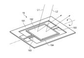
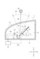
図1は、一実施形態に係る発光装置1の構成を例示している。発光装置1は、図2に例示される車両20に搭載される。本例においては、発光装置1は、車両20の左前部LFに配置されている。左前部LFは、車両20の左右方向における中央よりも左側、かつ車両20の前後方向における中央よりも前側に位置する領域である。車両20は、移動体の一例である。
Figure 1 illustrates an example of the configuration of a light-
図1に例示されるように、発光装置1は、ハウジング11と透光カバー12を備えている。ハウジング11は、透光カバー12とともに灯室13を区画している。透光カバー12は、車両20の外面の一部を形成している。As illustrated in Fig. 1, the light-
発光装置1は、第一光源141を備えている。第一光源141は、灯室13内に配置されている。第一光源141は、第一の光L1を出射するように構成されている。第一の光L1は、可視波長である第一波長を含んでいる。本実施形態においては、第一光源141は、半導体発光素子により実現されている。半導体発光素子の例としては、発光ダイオード(LED)、レーザダイオード(LD)、EL素子が挙げられる。第一光源141は、ハロゲンランプなどのランプ光源により実現されてもよい。The
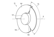
発光装置1は、回転リフレクタ15を備えている。回転リフレクタ15は、灯室13内に配置されている。図3に例示されるように、回転リフレクタ15は、基部151と複数の反射板152を備えている。基部151は、回転軸Aを中心として回転可能な円筒形状の部材として構成されている。複数の反射板152は、基部151の外周面に固定されている。複数の反射板152は、基部151の回転方向に沿って配列されている。The
図1に例示されるように、回転リフレクタ15は、第一光源141から出射された第一の光L1が複数の反射板152の一つに入射するように配置されている。複数の反射板152の一つにより反射された第一の光L1は、透光カバー12を通過して車両20の前方に位置する領域へ向かう。1, the rotating
各反射板152の形状および配置は、反射された第一の光L1の進行方向が、回転リフレクタ15の回転に伴って車両20の左右方向へ変化するように定められている。換言すると、各反射板152は、回転リフレクタ15の回転に伴って第一の光L1の進路を横切りながら、第一の光L1の反射方向を車両20の左右方向へ変化させる。車両20の左右方向は、第一方向の一例である。The shape and arrangement of each
すなわち、回転リフレクタ15は、第一の光L1が車両20の左右方向へ走査されつつ車両20の外部を照明するように、回転しながら第一の光L1を反射する。図1においては、回転リフレクタ15の回転中に複数の反射板152の一つによって反射された第一の光L1が進みうる方向の範囲が、第一走査範囲SR1として例示されている。That is, the rotating
特定の反射板152が第一の光L1の進路を横切り終えると、回転リフレクタ15の回転方向に隣接する別の反射板152が第一の光L1の進路を横切り始める。これにより、第一の光L1による第一走査範囲SR1の走査が繰り返される。When a
車両20の上下方向に配列された複数の第一光源141から出射された第一の光L1を回転リフレクタ15で車両20の左右方向へ走査することにより、車両20の前方に位置する第一走査範囲SR1に対応する領域に二次元的な配光パターンを形成できる。あるいは、第一光源141から出射された第一の光L1の車両20の左右方向への走査を繰り返しながら回転リフレクタ15を車両20の上下方向へスイブルさせることによっても、二次元的な配光パターンを形成できる。回転リフレクタ15による第一の光L1の反射方向と第一光源141の点消灯動作を同期させれば、配光パターン内の特定の位置に非照明領域を形成することもできる。車両20の前方に位置する第一走査範囲SR1に対応する領域は、第一領域の一例である。車両の前方は、移動体の進路の一例である。
A two-dimensional light distribution pattern can be formed in an area corresponding to the first scanning range SR1 located in front of the
図3に例示されるように、各反射板152は、回転リフレクタ15の回転方向に沿う周長CLを有している(符号CLは、一つの反射板152についてのみ示されている)。この周長CLは、第一の光L1による第一走査範囲SR1の走査が繰り返される周期に対応している。3, each
図1に例示されるように、発光装置1は、第一基板161を備えている。第一基板161は、灯室13内に配置されている。第一基板161は、第一光源141を支持している。図示を省略するが、第一基板161上には、第一光源141の動作を制御するための回路が形成されうる。1, the
発光装置1は、第二光源142を備えている。第二光源142は、灯室13内に配置されている。第二光源142は、第二の光L2を出射するように構成されている。第二の光L2は、車両20の外部を照明する第一の光L1とは異なる機能に割り当てられている。本実施形態においては、第二の光L2は、測距機能を実現するために、赤外波長である第二波長を含んでいる。すなわち、第一の光L1の波長と第二の光L2の波長とは、相違している。The light-emitting
本実施形態においては、第二光源142は、半導体発光素子により実現されている。半導体発光素子の例としては、発光ダイオード(LED)、レーザダイオード(LD)、EL素子が挙げられる。第二光源142は、赤外線ランプなどのランプ光源により実現されてもよい。In this embodiment, the second
発光装置1は、第二基板162を備えている。第二基板162は、灯室13内に配置されている。第二基板162は、第二光源142を支持している。図示を省略するが、第二基板162上には、第二光源142の点消灯動作を制御するための回路が形成されうる。The
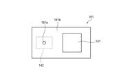
第一基板161は、開口部161aを有している。開口部161aは、第一基板161の第一主面161bと第二主面161cにおいて開口しており、両主面を連通するように延びている。第一光源141は、第一主面161b上に配置されている。本明細書で用いられる「基板の主面」という語は、当該基板を形成している複数の面のうち最大の面積を有する面を意味する。The
第一基板161は第二光源142から出射された第二の光L2の進路を横切るように配置されているが、開口部161aが第二の光L2の通過を許容している。具体的には、第二光源142から出射された第二の光L2は、第二主面161cの側から開口部161aに入り、第一主面161bの側へ出る。The
開口部161aを通過した第二の光L2は、回転リフレクタ15における複数の反射板152の一つに入射する。複数の反射板152の一つにより反射された第二の光L2は、透光カバー12を通過して車両20の前方に位置する領域へ向かう。The second light L2 that passes through the
第一の光L1と同様に、各反射板152は、回転リフレクタ15の回転に伴って第二の光L2の進路を横切りながら、第二の光L2の反射方向を車両20の左右方向へ変化させる。すなわち、回転リフレクタ15は、第二の光L2が車両20の左右方向へ走査されつつ車両20の外部へ向かうように、回転しながら第二の光L2を反射する。図1においては、回転リフレクタ15の回転中に複数の反射板152の一つによって反射された第二の光L2が進みうる方向の範囲が、第二走査範囲SR2として例示されている。As with the first light L1, each
特定の反射板152が第二の光L2の進路を横切り終えると、回転リフレクタ15の回転方向に隣接する別の反射板152が第二の光L2の進路を横切り始める。これにより、第二の光L2による第二走査範囲SR2の走査が繰り返される。When a
発光装置1は、受光素子10を備えている。受光素子10は、灯室13内に配置されている。受光素子10は、車両20の前方に位置する第二走査範囲SR2に対応する領域内の物体に第二の光L2が反射された結果として得られる戻り光L2’を検出するように構成されている。すなわち、受光素子10は、第二の光L2の波長に感度を有し、入射した戻り光L2’の強度に応じた信号を出力するように構成されている。受光素子10の例としては、フォトダイオード、フォトトランジスタ、フォトレジスタが挙げられる。車両20の前方に位置する第二走査範囲SR2に対応する領域は、第二領域の一例である。第一領域と第二領域は、少なくとも一部が重なっていてもよいし、重なっていなくてもよい。The
第二光源142から第二の光L2が出射されたタイミングから受光素子10により戻り光L2’が検出されるまでの時間に基づいて、戻り光L2’に関連付けられた物体までの距離を取得できる。そのような距離情報を回転リフレクタ15による走査方向と関連付けて集積することにより、戻り光L2’に関連付けられた物体の形状に係る情報も取得できる。これらの処理は、不図示の処理装置により行なわれうる。処理装置は、灯室13内に配置されてもよいし、ハウジング11の外側に配置されてもよい。処理装置の機能は、車両20に搭載されている制御装置によって実現されてもよい。Based on the time from when the second light L2 is emitted from the second
回転リフレクタ15のような走査光学系を用いると、より少ない数の光源で広範囲に出射光を到達させることができる。他方、走査光学系は、ある程度の設置スペースを必要とする。上記のような構成によれば、車両20の外部を照明するための第一の光L1とは異なる機能を第二の光L2に割り当て、かつ第一の光L1を走査するために用いられる回転リフレクタ15を第二の光L2の走査にも共用できる。これにより、相違する機能に割り当てられた第一の光L1と第二の光L2について走査光学系を適用しつつも、設置スペースの増大を抑制できる。したがって、発光装置1の多機能化を実現しつつも、大型化を抑制できる。
By using a scanning optical system such as the rotating
例えば、第二の光L2として赤外光を使用することにより、測距機能を実現できる。あるいは、可視波長を含む第二の光L2を回転リフレクタ15に路面へ向けて反射させ、第二光源142の点消灯動作と回転リフレクタ15の回転動作を適宜に同期させることにより、第二走査範囲SR2内に位置する路面に特定のマークなどの情報を描画できる。For example, a distance measurement function can be realized by using infrared light as the second light L2. Alternatively, the second light L2 containing visible wavelengths can be reflected by the rotating
図4に例示されるように、本実施形態においては、開口部161aを通過した第二の光のL2の進行方向に対応する第一主面161bの法線方向から見ると、第二光源142は、第一基板161の背後に隠れるように配置されている。As illustrated in FIG. 4, in this embodiment, when viewed from the normal direction of the first
このような構成によれば、特に第一基板161の主面に沿う方向における発光装置1の大型化を抑制できる。
With this configuration, it is possible to prevent the
図4に例示されるように、本実施形態においては、第一基板161に形成された開口部161aは、ピンホールである。ピンホールは、第一基板161の第一主面161bおよび第二主面161cの法線方向から見て円形の断面を有している。換言すると、開口部161aの断面形状は、第一基板161の第一主面161bおよび第二主面161cの法線方向から見て等方性を有している。4, in this embodiment, the
ピンホールの半径rは、例えば次式により定められうる。
r2=λb
λは、第二の光L2の波長である。bは、回転リフレクタ15の反射板152に対する焦点距離である。
The radius r of the pinhole can be determined, for example, by the following formula:
r2 = λb
λ is the wavelength of the second light L2, and b is the focal length of the
ピンホールは限られたスペースに形成可能であるので、第一基板161における第一光源141およびその駆動回路のレイアウトに与える影響が小さい。また、第一主面161bと第二主面161cの法線方向にピンホールを通過する第二の光L2により形成される光スポットの形状に等方性を確保しやすくなるので、光学系の複雑化を抑制できる。したがって、非常に簡易な手法かつ高い自由度で、第一光源141と第二光源142が回転リフレクタ15を共用する光学系を構成できる。Since the pinhole can be formed in a limited space, it has little effect on the layout of the first
しかしながら、開口部161aの断面形状は、第一主面161bまたは第二主面161cの法線方向から見て、短手方向と長手方向を有してもよい。そのような開口部161aの形状の例としては、スリットや切欠きが挙げられる。その場合、回転リフレクタ15による走査方向に対応する第一基板161上の方向が短手方向となるように、スリットや切欠きが形成されることが好ましい。この場合、開口部161aを通過した第二の光L2により形成される光スポットの走査方向に沿う方向の寸法を小さくできるので、走査分解能の低下を抑制できる。However, the cross-sectional shape of the
図1に例示されるように、発光装置1は、集光光学系17を備えうる。集光光学系17は、第二光源142から出射された第二の光L2を、開口部161aに向けて集光するように構成と配置が定められている。1, the light-emitting
このような構成によれば、第二光源142から出射された第二の光L2に効率よく開口部161aを通過させることができる。したがって、第二の光L2の利用効率を高めることができる。With this configuration, the second light L2 emitted from the second
上記の実施形態は、本開示の理解を容易にするための例示にすぎない。上記の実施形態に係る構成は、本開示の趣旨を逸脱しなければ、適宜に変更・改良されうる。The above embodiments are merely examples to facilitate understanding of the present disclosure. The configurations according to the above embodiments may be modified or improved as appropriate without departing from the spirit and scope of the present disclosure.
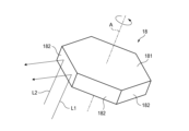
上記の実施形態においては、第一の光L1および第二の光L2を所望の方向へ走査することができれば、回転リフレクタ15は、図5に例示されるポリゴンミラー18や、図6に例示されるMEMSミラー19で置き換えられうる。In the above embodiment, if the first light L1 and the second light L2 can be scanned in the desired direction, the rotating
ポリゴンミラー18は、回転軸Aを中心として回転可能な基部181を有している。基部181は、回転軸Aの延びる方向から見て多角形状の断面を有している。当該多角形状の各辺に対応する部分に反射板182が配置される。基部181が回転軸Aを中心として回転すると、複数の反射板182の一つが第一の光L1と第二の光L2の進路を横切りつつ、第一の光L1と第二の光L2の反射方向を変更する。特定の反射板182が第一の光L1と第二の光L2の進路を横切り終えると、ポリゴンミラー18の回転方向に隣接する別の反射板182が第一の光L1と第二の光L2の進路を横切り始める。これにより、第一の光L1による第一走査範囲SR1と第二の光L2による第二走査範囲SR2の走査が繰り返される。The
MEMSミラー19は、フレーム191、反射板192、トーションバー193、およびコイル194を備えている。反射板192は、トーションバー193を介してフレーム191に支持されている。不図示の磁石から生じた磁界内にコイル194を配置して電流を流すことにより、トーションバー193を中心として反射板192を回動させる力が生じる。反射板192の回動に伴い、第一の光L1と第二の光L2の反射方向が変化する。反射板192の回動が繰り返されることにより、第一の光L1による第一走査範囲SR1と第二の光L2による第二走査範囲SR2の走査が繰り返される。The
発光装置1は、車両20の右前部RFにも搭載されうる。右前部RFは、車両20の左右方向における中央よりも右側、かつ車両20の前後方向における中央よりも前側に位置する領域である。右前部RFに搭載される発光装置1は、図1に例示された発光装置1と左右対称の構成を有しうる。The light-emitting
発光装置1は、車両20の左後部LBと右後部RBにも搭載されうる。左後部LBは、車両20の左右方向における中央よりも左側、かつ車両20の前後方向における中央よりも後側に位置する領域である。右後部RBは、車両20の左右方向における中央よりも右側、かつ車両20の前後方向における中央よりも後側に位置する領域である。左後部LBに搭載される発光装置1は、図1に例示された発光装置1と前後対称の構成を有しうる。右後部RBに搭載される発光装置1は、左後部LBに搭載される発光装置1と左右対称の構成を有しうる。The light-emitting
発光装置1が搭載される移動体は、車両20に限られない。その他の移動体の例としては、鉄道、飛行体、航空機、船舶などが挙げられる。発光装置1が搭載される移動体は、運転者を必要としなくてもよい。The moving body on which the light-emitting
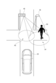
発光装置1は、移動体に搭載されることを要しない。図7に例示されるように、発光装置1は、街路灯30や交通信号機40などの交通インフラ設備にも搭載されうる。The light-emitting
発光装置1が街路灯30に搭載される場合、第一光源141から出射される可視光により領域A1が照明されるとともに、第二光源142から出射される赤外光により領域A1内に位置する歩行者50や車両などが検出されうる。歩行者50もまた移動体の一例である。領域A1は、移動体の進路の一例である。例えば、赤外光を用いた測距機能により歩行者50や車両が交差点に進入しようとしていることが検出されると、当該情報が通信を介して別方向から当該交差点に進入しようとしている車両20へ通知されうる。When the light-emitting
発光装置1が交通信号機40に搭載される場合、交通道路面上の領域A2に情報を描画するために第一光源141が使用されうる。領域A2は、移動体の進路の一例である。上記の例と同様に、第二光源142から出射される赤外光は、領域A1内に位置する歩行者50や車両などを検出するために使用されうる。例えば、赤外光を用いた測距機能により歩行者50や車両が交差点に進入しようとしていることが検出されると、別方向から当該交差点に進入しようとしている車両20に注意を促す情報(文字、標識、点滅する警戒色など)が領域A2に描画されうる。When the light-emitting
発光装置1は、住宅や施設などに設置される照明装置にも搭載されうる。例えば、当該照明装置は、第二光源142から出射される赤外光を用いて所定の領域に進入した移動体が検知されると、第一光源141を点灯して当該領域を照明するように構成されうる。The light-emitting
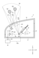
図8は、一実施形態に係るセンサユニット2の構成を例示している。センサユニット2は、図2に例示される車両20に搭載される。本例においては、センサユニット2は、車両20の左前部LFに配置されている。
Figure 8 illustrates an example of the configuration of a
図8に例示されるように、センサユニット2は、ハウジング21と透光カバー22を備えている。ハウジング21は、透光カバー22とともに収容空間23を区画している。透光カバー22は、車両20の外面の一部を形成している。As illustrated in Figure 8, the
センサユニット2は、発光素子241を備えている。発光素子241は、収容空間23内に配置されている。発光素子241は、検出光SLを出射するように構成されている。発光素子241から出射された検出光SLは、透光カバー22を通過して車両20の前方に位置する領域へ向かう。本実施形態においては、検出光SLは、赤外波長を含んでいる。The
本実施形態においては、発光素子241は、半導体発光素子により実現されている。半導体発光素子の例としては、発光ダイオード(LED)、レーザダイオード(LD)、EL素子が挙げられる。発光素子241は、ハロゲンランプなどのランプ光源により実現されてもよい。In this embodiment, the light-emitting
センサユニット2は、受光素子242を備えている。受光素子242は、収容空間23内に配置されている。受光素子242は、検出光SLが検出可能領域DA内に存在する物体に反射された結果として得られる戻り光RLを検出するように構成されている。すなわち、受光素子242は、検出光SLの波長に感度を有し、入射した戻り光RLの強度に応じた検出信号DSを出力するように構成されている。受光素子242は、フォトダイオード、フォトトランジスタ、フォトレジスタなどにより実現されうる。本例においては、検出可能領域DAは、車両20の前方に設定されている。車両20の前方は、移動体の進路の一例である。The
センサユニット2は、回転リフレクタ25を備えている。回転リフレクタ25は、収容空間23内に配置されている。回転リフレクタ25は、基部251および複数の反射板252を備えている。回転リフレクタ25の構成は、図3に例示された回転リフレクタ15の構成と同じであるので、繰り返しとなる説明を省略する。The
図8に例示されるように、回転リフレクタ25は、検出可能領域DAから到来する戻り光RLが複数の反射板252の一つに入射するように配置されている。複数の反射板252の一つにより反射された戻り光RLは、受光素子242へ向かう。8, the rotating
各反射板252の形状および配置は、受光素子242へ向けて反射される戻り光RLが生じうる検出可能領域DA内の位置が、回転リフレクタ25の回転に伴って車両20の左右方向へ変化するように定められている。換言すると、各反射板252の形状および配置は、受光素子242へ向けて反射される戻り光RLの入射方向が、回転リフレクタ25の回転に伴って車両20の左右方向へ変化するように定められている。車両20の左右方向は、第一方向の一例である。The shape and arrangement of each
図8に示される例においては、検出可能領域DA内に物体601と物体602が位置している。発光素子241から出射される検出光SLは検出可能領域DA全体に照射されるので、物体601と物体602は、同時に戻り光RLを生じている。In the example shown in Figure 8, objects 601 and 602 are located within the detectable area DA. Since the detection light SL emitted from the light-emitting
前述の構成によれば、回転リフレクタ25の反射板252にある位置と姿勢をとる時点t1において、物体601により生じた戻り光RLが受光素子242へ反射される経路が形成される。そして、反射板252が別の位置と姿勢をとる時点t2において、検出可能領域DA内の別の位置にある物体602により生じた戻り光RLが受光素子242へ反射される経路が形成される。本明細書においては、このようにして反射板252に対する角度が異なる検出可能領域DA内の複数の位置からの戻り光RLを順次反射する動作を、「反射走査」と称する。
According to the above-mentioned configuration, at time t1 when the
特定の反射板252による検出可能領域DAの反射走査が完了すると、回転リフレクタ25の回転方向に隣接する別の反射板252が検出可能領域DAの反射走査を開始する。これにより、回転リフレクタ25の回転に伴い、検出可能領域DAの反射走査が繰り返される。When a reflective scan of the detectable area DA by a
各反射板252は、回転リフレクタ25の回転方向に沿う周長を有している)。この周長は、回転リフレクタ25による検出可能領域DAの反射走査が繰り返される周期に対応している。Each
センサユニット2は、処理装置26を備えている。処理装置26は、発光素子241の動作を制御する制御信号CS1を出力するように構成されている。処理装置26は、受光素子242から出力された検出信号DSを受け付けるように構成されている。処理装置26は、回転リフレクタ25の回転動作を制御する制御信号CS2を出力するように構成されている。The
処理装置26は、回転軸Aを中心とする回転リフレクタ25の回転角度と関連付けて検出信号DSを受け付けるように構成されている。具体的には、制御信号CS2に基づいて回転リフレクタ25の回転角度が特定されうる。回転リフレクタ25の回転角度を特定することにより、複数の反射板252のいずれが反射走査を行なっているのか、検出可能領域DA内のいずれの位置からの戻り光RLが受光素子242へ反射されているのかを特定できる。The
広がりを有する検出可能領域DAからの戻り光を同時に検出しようとする場合、複数の受光素子が一次元的あるいは二次元的に配列されたアレイが必要になる。この場合、受光素子を設置するためにより広いスペースが必要になる。また、検出可能領域DA内の情報の検出分解能は、アレイを構成している複数の受光素子の数に依存する。 When attempting to simultaneously detect return light from a detectable area DA that has a large area, an array in which multiple light receiving elements are arranged one-dimensionally or two-dimensionally is required. In this case, a larger space is required to install the light receiving elements. Furthermore, the detection resolution of the information within the detectable area DA depends on the number of multiple light receiving elements that make up the array.
他方、本実施形態の構成によれば、検出可能領域DA内の異なる位置からの戻り光RLが、回転リフレクタ25の回転に伴って受光素子242へ向けて順次反射され、反射に供される戻り光RLの到来元の位置が回転リフレクタ25の回転角度位置と関連付けて特定されうるので、少なくとも一つの受光素子242を用いて広がりを有する検出可能領域DA内の情報を取得できる。また、当該情報の検出分解能は、受光素子242の数(空間分解能)ではなく、回転リフレクタ25の回転速度と検出信号DSの取得サイクル(時間分解能)に依存させることができる。したがって、車両20の前方に位置する領域の情報を検出する構造の大型化と情報を検出する能力の低下を抑制できる。On the other hand, according to the configuration of this embodiment, the return light RL from different positions within the detectable area DA is sequentially reflected toward the
車両20の前方に位置する領域の情報の一例として、発光素子241から検出光SLが出射されたタイミングから、ある回転位置の回転リフレクタ25により反射された戻り光RLが受光素子242に検出されるタイミングまでの時間に基づいて、当該回転位置に関連付けられた検出可能領域DA内の位置における物体までの距離が特定されうる。As an example of information about the area located in front of the
車両20の前方に位置する領域の情報の別例として、発光素子241から出射された検出光SLの波形と、ある回転位置の回転リフレクタ25により反射されて受光素子242により検出された戻り光RLの波形との相違に基づいて、当該回転位置に関連付けられた検出可能領域DA内の位置における物体の材質などの属性が特定されうる。As another example of information about the area located in front of the
上記の機能を有する処理装置26は、汎用メモリと協働して動作する汎用マイクロプロセッサとして提供されてもよいし、専用集積回路素子として提供されてもよい。汎用マイクロプロセッサとしては、CPU、MPU、GPUなどが例示されうる。汎用メモリとしては、RAMやROMが例示されうる。専用集積回路素子としては、マイクロコントローラ、ASIC、FPGAなどが例示されうる。処理装置26は、汎用マイクロプロセッサと専用集積回路素子の組合せにより実現されてもよい。The
センサユニット2は、第一結像光学系201を備えうる。第一結像光学系201は、回転リフレクタ25へ向けて戻り光RLを集光するように構成と配置が定められている。The
このような構成によれば、検出可能領域DAの広さを維持しつつ、回転リフレクタ25において戻り光RLを反射するために必要な領域の面積を低減できる。回転リフレクタ25の大型化を抑制できるので、情報を検出する構成の大型化をさらに抑制できる。
With this configuration, it is possible to reduce the area of the area required to reflect the return light RL in the
センサユニット2は、第二結像光学系202を備えうる。第二結像光学系202は、回転リフレクタ25により反射された戻り光RLを、受光素子242の受光面に向けて集光するように構成と配置が定められている。The
このような構成によれば、検出可能領域DA内に位置する物体からの戻り光RLを効率よく受光素子242の受光面に結像させることができ、検出可能領域DA内の情報の検出分解能の低下をさらに抑制できる。
With this configuration, the return light RL from an object located within the detectable area DA can be efficiently imaged on the light receiving surface of the
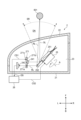
図9は、別実施形態に係るセンサユニット2の構成を例示している。図8に例示された構成と実質的に同一の要素については同一の参照符号を付与し、繰り返しとなる説明は省略する。
Figure 9 illustrates the configuration of a
本実施形態においては、発光素子241から出射された検出光SLもまた回転リフレクタ25による反射に供される。発光素子241は、出射された検出光SLが複数の反射板252の一つに入射するように配置されている。複数の反射板252の一つにより反射された検出光SLは、透光カバー22を通過して車両20の前方に位置する領域へ向かう。In this embodiment, the detection light SL emitted from the light-emitting
各反射板252の形状および配置は、反射された検出光SLの進行方向が、回転リフレクタ25の回転に伴って車両20の左右方向へ変化するように定められている。換言すると、各反射板252は、回転リフレクタ25の回転に伴って検出光SLの進路を横切りながら、検出光SLの反射方向を車両20の左右方向へ変化させる。The shape and arrangement of each
すなわち、回転リフレクタ25は、検出光SLが車両20の左右方向へ走査されつつ車両20の外部へ向かうように、回転しながら検出光SLを反射する。図9においては、回転リフレクタ25の回転中に複数の反射板252の一つによって反射された検出光SLが進みうる方向の範囲が、走査範囲SRとして例示されている。That is, the rotating
特定の反射板252が検出光SLの進路を横切り終えると、回転リフレクタ25の回転方向に隣接する別の反射板252が検出光SLの進路を横切り始める。これにより、検出光SLによる走査範囲SRの走査が繰り返される。When a
本実施形態においては、センサユニット2は、基板271を備えている。基板271は、収容空間23内に配置されている。基板271は、発光素子241を支持している。図示を省略するが、基板271上には、発光素子241の動作を制御するための回路が形成されうる。In this embodiment, the
基板271には、ピンホール271aが形成されている。ピンホール271aは、基板271の第一主面271bと第二主面271cにおいて開口しており、両主面を連通するように延びている。発光素子241は、第一主面271b上に配置されている。A
基板271は回転リフレクタ25に反射された戻り光RLの進路を横切るように配置されているが、ピンホール271aが戻り光RLの通過を許容している。具体的には、回転リフレクタ25に反射された戻り光RLは、第一主面271bの側からピンホール271aに入り、第二主面271cの側へ出る。ピンホール271aを通過した戻り光RLは、受光素子242に入射する。The
図10に例示されるように、ピンホール271aは、基板271の第一主面271bおよび第二主面271cの法線方向から見て円形の断面を有している。換言すると、ピンホール271aの断面形状は、基板271の第一主面271bおよび第二主面271cの法線方向から見て等方性を有している。10, the
ピンホールの半径rは、例えば次式により定められうる。
r2=λb
λは、戻り光RLの波長である。bは、受光素子242に対する焦点距離である。
The radius r of the pinhole can be determined, for example, by the following formula:
r2 = λb
λ is the wavelength of the return light RL, and b is the focal length for the
上記のように構成されたピンホール271aは、前述した第二結像光学系として機能しうる。ピンホール271aは限られたスペースに形成可能であるので、基板271における発光素子241およびその駆動回路のレイアウトに与える影響が小さい。また、第一主面271bと第二主面271cの法線方向にピンホール271aを通過する戻り光RLにより形成される光スポットの形状に等方性を確保しやすくなるので、光学系の複雑化を抑制できる。したがって、非常に簡易な手法かつ高い自由度で、結像光学系を構成できる。The
ピンホール271aを利用した結像光学系は、発光素子241から出射された検出光SLが回転リフレクタ25に反射されることなく車両20の外部へ向かう、図8に例示された構成にも適用可能である。ピンホール271aは、回転リフレクタ25により反射された戻り光RLが受光素子242に至る経路上に配置される適宜の基板に形成されうる。The imaging optical system using the pinhole 271a can also be applied to the configuration illustrated in FIG. 8, in which the detection light SL emitted from the light-emitting
なお、図11に例示されるように、受光素子242は、発光素子241を支持している基板271と回転リフレクタ25の間に配置されうる。すなわち、回転リフレクタ25により反射された戻り光RLが、基板271を通過することなく受光素子242により受光されうる。この場合、受光素子242に入射する戻り光RLの強度の低下を抑制できる。11, the
上記の実施形態は、本開示の理解を容易にするための例示にすぎない。上記の実施形態に係る構成は、本開示の趣旨を逸脱しなければ、適宜に変更・改良されうる。The above embodiments are merely examples to facilitate understanding of the present disclosure. The configurations according to the above embodiments may be modified or improved as appropriate without departing from the spirit and scope of the present disclosure.
反射走査を遂行しつつ戻り光RLを受光素子242へ向けて反射することができれば、回転リフレクタ25は、図5に例示されるポリゴンミラー18や、図6に例示されるMEMSミラー19で置き換えられうる。If it is possible to reflect the return light RL toward the
ポリゴンミラー18の基部181が回転軸Aを中心として回転すると、受光素子242へ向けて反射される戻り光RLの入射角度が変化する。特定の反射板182が検出可能領域DAの反射走査を終えると、ポリゴンミラー18の回転方向に隣接する別の反射板182が検出可能領域DAの反射走査を開始する。これにより、検出可能領域DAの反射走査が繰り返される。When the
MEMSミラー19の反射板192の回動に伴い、受光素子242へ向けて反射される戻り光RLの入射角度が変化する。反射板192の回動が繰り返されることにより、検出可能領域DAの反射走査が繰り返される。As the
センサユニット2は、車両20の右前部RFにも搭載されうる。右前部RFに搭載されるセンサユニット2は、図8に例示されたセンサユニット2と左右対称の構成を有しうる。The
センサユニット2は、車両20の左後部LBと右後部RBにも搭載されうる。左後部LBに搭載されるセンサユニット2は、図8に例示されたセンサユニット2と前後対称の構成を有しうる。右後部RBに搭載されるセンサユニット2は、左後部LBに搭載されるセンサユニット2と左右対称の構成を有しうる。The
センサユニット2が搭載される移動体は、車両20に限られない。その他の移動体の例としては、鉄道、飛行体、航空機、船舶などが挙げられる。センサユニット2が搭載される移動体は、運転者を必要としなくてもよい。The moving body on which the
センサユニット2は、移動体に搭載されることを要しない。図7に例示されるように、センサユニット2は、街路灯30や交通信号機40などの交通インフラ設備にも搭載されうる。The
センサユニット2が街路灯30に搭載される場合、発光素子241から出射される検出光SLにより領域A1内に位置する歩行者50や車両などが検出されうる。歩行者50もまた移動体の一例である。領域A1は、移動体の進路の一例である。When the
センサユニット2が交通信号機40に搭載される場合、発光素子241から出射される検出光SLは、領域A1内に位置する歩行者50や車両などを検出するために使用されうる。例えば、歩行者50や車両が交差点に進入しようとしていることが検出されると、可視光を出射する別光源により、別方向から当該交差点に進入しようとしている車両20に注意を促す情報(文字、標識、点滅する警戒色など)が領域A2に描画されうる。When the
本出願の記載の一部を構成するものとして、2020年3月9日に提出された日本国特許出願2020-039752号、2020年3月9日に提出された日本国特許出願2020-039753号、2020年12月18日に提出された日本国特許出願2020-210429号、および2020年12月18日に提出された日本国特許出願2020-210430号の内容が援用される。The contents of Japanese Patent Application No. 2020-039752 filed on March 9, 2020, Japanese Patent Application No. 2020-039753 filed on March 9, 2020, Japanese Patent Application No. 2020-210429 filed on December 18, 2020, and Japanese Patent Application No. 2020-210430 filed on December 18, 2020 are incorporated by reference as part of the description of this application.
Claims (6)
前記第一波長と異なる第二波長を含む第二の光を出射する第二光源と、
前記第一光源を支持するとともに、前記第二の光の通過を許容する開口部を有している基板と、
前記第一の光が第一方向へ走査されつつ第一領域を照射するように、かつ前記開口部を通過した前記第二の光が当該第一方向へ走査されつつ第二領域へ向かうように、回転または回動しつつ前記第一の光および前記第二の光を反射するミラーと、
を備えており、
前記開口部は、ピンホールである、
発光装置。 A first light source that emits a first light having a first wavelength that is a visible wavelength;
A second light source that emits a second light having a second wavelength different from the first wavelength;
a substrate supporting the first light source and having an opening for allowing the second light to pass therethrough;
a mirror that rotates or pivots to reflect the first light and the second light so that the first light is scanned in a first direction to irradiate a first region, and the second light that has passed through the opening is scanned in the first direction to travel toward a second region;
Equipped with
The opening is a pinhole.
Light emitting device.
請求項1に記載の発光装置。 When the substrate is viewed from a traveling direction of the second light that has passed through the opening, the second light source is disposed so as to be hidden behind the substrate.
The light emitting device according to claim 1 .
前記第一波長と異なる第二波長を含む第二の光を出射する第二光源と、
前記第一光源を支持するとともに、前記第二の光の通過を許容する開口部を有している基板と、
前記第一の光が第一方向へ走査されつつ第一領域を照射するように、かつ前記開口部を通過した前記第二の光が当該第一方向へ走査されつつ第二領域へ向かうように、回転または回動しつつ前記第一の光および前記第二の光を反射するミラーと、
前記第二の光を前記開口部へ向けて集光する集光光学系と、
を備えている、
発光装置。 A first light source that emits a first light having a first wavelength that is a visible wavelength;
A second light source that emits a second light having a second wavelength different from the first wavelength;
a substrate supporting the first light source and having an opening for allowing the second light to pass therethrough;
a mirror that rotates or pivots to reflect the first light and the second light so that the first light is scanned in a first direction to irradiate a first region, and the second light that has passed through the opening is scanned in the first direction to travel toward a second region;
a focusing optical system that focuses the second light toward the opening;
Equipped with
Light emitting device.
請求項1から3のいずれか一項に記載の発光装置。 a light receiving element for detecting return light generated when the second light is reflected by an object located in the second area,
A light emitting device according to claim 1 .
請求項1から4のいずれか一項に記載の発光装置。 The second wavelength is an infrared wavelength.
A light emitting device according to claim 1 .
請求項1から5のいずれか一項に記載の発光装置。 The first area and the second area are set to be located on a path of a moving object.
A light emitting device according to claim 1 .
Priority Applications (1)
| Application Number | Priority Date | Filing Date | Title |
|---|---|---|---|
| JP2024190360A JP2025010302A (en) | 2020-03-09 | 2024-10-30 | Sensor Unit |
Applications Claiming Priority (9)
| Application Number | Priority Date | Filing Date | Title |
|---|---|---|---|
| JP2020039753 | 2020-03-09 | ||
| JP2020039752 | 2020-03-09 | ||
| JP2020039752 | 2020-03-09 | ||
| JP2020039753 | 2020-03-09 | ||
| JP2020210430 | 2020-12-18 | ||
| JP2020210429 | 2020-12-18 | ||
| JP2020210430 | 2020-12-18 | ||
| JP2020210429 | 2020-12-18 | ||
| PCT/JP2021/008167 WO2021182231A1 (en) | 2020-03-09 | 2021-03-03 | Light-emitting device and sensor unit |
Related Child Applications (1)
| Application Number | Title | Priority Date | Filing Date |
|---|---|---|---|
| JP2024190360A Division JP2025010302A (en) | 2020-03-09 | 2024-10-30 | Sensor Unit |
Publications (2)
| Publication Number | Publication Date |
|---|---|
| JPWO2021182231A1 JPWO2021182231A1 (en) | 2021-09-16 |
| JP7581323B2 true JP7581323B2 (en) | 2024-11-12 |
Family
ID=77671637
Family Applications (2)
| Application Number | Title | Priority Date | Filing Date |
|---|---|---|---|
| JP2022505971A Active JP7581323B2 (en) | 2020-03-09 | 2021-03-03 | Light-emitting device |
| JP2024190360A Pending JP2025010302A (en) | 2020-03-09 | 2024-10-30 | Sensor Unit |
Family Applications After (1)
| Application Number | Title | Priority Date | Filing Date |
|---|---|---|---|
| JP2024190360A Pending JP2025010302A (en) | 2020-03-09 | 2024-10-30 | Sensor Unit |
Country Status (3)
| Country | Link |
|---|---|
| JP (2) | JP7581323B2 (en) |
| CN (1) | CN115244332A (en) |
| WO (1) | WO2021182231A1 (en) |
Families Citing this family (1)
| Publication number | Priority date | Publication date | Assignee | Title |
|---|---|---|---|---|
| JP7258115B1 (en) | 2021-12-24 | 2023-04-14 | 株式会社ライトショー・テクノロジー | projection display |
Citations (2)
| Publication number | Priority date | Publication date | Assignee | Title |
|---|---|---|---|---|
| JP2015044586A (en) | 2010-04-13 | 2015-03-12 | 株式会社小糸製作所 | Vehicle monitoring device and obstacle detection device |
| JP2019216013A (en) | 2018-06-13 | 2019-12-19 | 株式会社小糸製作所 | Vehicle lamp |
Family Cites Families (9)
| Publication number | Priority date | Publication date | Assignee | Title |
|---|---|---|---|---|
| JP4960599B2 (en) * | 2005-03-23 | 2012-06-27 | 三井造船株式会社 | Collision prevention device and vehicle equipped with collision prevention device |
| JP2016125970A (en) * | 2015-01-08 | 2016-07-11 | 株式会社リコー | Optical scanning device, distance measurement device, and mobile body device |
| JP6510381B2 (en) * | 2015-10-13 | 2019-05-08 | 浜松ホトニクス株式会社 | Ranging device |
| WO2018091970A1 (en) * | 2016-11-16 | 2018-05-24 | Innoviz Technologies Ltd. | Lidar systems and methods |
| JP6809946B2 (en) * | 2017-03-17 | 2021-01-06 | トヨタ自動車株式会社 | Vehicle headlight device |
| CN107131463A (en) * | 2017-05-25 | 2017-09-05 | 上海小糸车灯有限公司 | A kind of projection lens set with different imaging capabilities |
| US11592527B2 (en) * | 2018-02-16 | 2023-02-28 | Cepton Technologies, Inc. | Systems for incorporating LiDAR sensors in a headlamp module of a vehicle |
| CN111868434B (en) * | 2018-03-14 | 2022-04-12 | 株式会社小糸制作所 | Lamp unit |
| JP6979591B2 (en) * | 2018-06-26 | 2021-12-15 | パナソニックIpマネジメント株式会社 | Lighting device and light emitting device |
-
2021
- 2021-03-03 WO PCT/JP2021/008167 patent/WO2021182231A1/en not_active Ceased
- 2021-03-03 CN CN202180020243.XA patent/CN115244332A/en active Pending
- 2021-03-03 JP JP2022505971A patent/JP7581323B2/en active Active
-
2024
- 2024-10-30 JP JP2024190360A patent/JP2025010302A/en active Pending
Patent Citations (2)
| Publication number | Priority date | Publication date | Assignee | Title |
|---|---|---|---|---|
| JP2015044586A (en) | 2010-04-13 | 2015-03-12 | 株式会社小糸製作所 | Vehicle monitoring device and obstacle detection device |
| JP2019216013A (en) | 2018-06-13 | 2019-12-19 | 株式会社小糸製作所 | Vehicle lamp |
Also Published As
| Publication number | Publication date |
|---|---|
| CN115244332A (en) | 2022-10-25 |
| JP2025010302A (en) | 2025-01-20 |
| JPWO2021182231A1 (en) | 2021-09-16 |
| WO2021182231A1 (en) | 2021-09-16 |
Similar Documents
| Publication | Publication Date | Title |
|---|---|---|
| CN111853690B (en) | Light device for integrated LIDAR of vehicle | |
| JP6292534B2 (en) | Object detection device and sensing device | |
| US11333745B2 (en) | LIDAR integrated lamp apparatus of vehicle | |
| JP7732036B2 (en) | Infrared sensor system for vehicles | |
| EP3486557B1 (en) | Vehicular lamp | |
| JP6579303B2 (en) | Optical device and vehicle equipped with optical device | |
| WO2016072504A1 (en) | Illumination device and vehicle | |
| US20210208251A1 (en) | Lidar system including scanning field of illumination | |
| US11697369B2 (en) | LiDAR integrated lamp device for vehicle | |
| JP2025010302A (en) | Sensor Unit | |
| KR102663206B1 (en) | Lidar ntegrated lamp device for vehicle | |
| JP7379206B2 (en) | Vehicle lights | |
| JP7215838B2 (en) | Optical units and vehicle headlights | |
| CN114402162A (en) | Vehicle lighting system and vehicle lighting | |
| JP2020177854A (en) | Vehicle lighting equipment and road surface condition detection system | |
| JP7538607B2 (en) | Sensor unit and lighting device | |
| JP2023548794A (en) | Illumination device for automobile floodlights | |
| WO2020189289A1 (en) | Vehicle light and vehicle light system | |
| JP7340596B2 (en) | Vehicle lights | |
| JP6203541B2 (en) | Rear fog lamp device | |
| JP2020080281A (en) | Vehicular headlight | |
| KR20170080301A (en) | The Apparatus And Method For Parking Guide |
Legal Events
| Date | Code | Title | Description |
|---|---|---|---|
| A621 | Written request for application examination |
Free format text: JAPANESE INTERMEDIATE CODE: A621 Effective date: 20231225 |
|
| A131 | Notification of reasons for refusal |
Free format text: JAPANESE INTERMEDIATE CODE: A131 Effective date: 20240702 |
|
| A521 | Request for written amendment filed |
Free format text: JAPANESE INTERMEDIATE CODE: A523 Effective date: 20240724 |
|
| TRDD | Decision of grant or rejection written | ||
| A01 | Written decision to grant a patent or to grant a registration (utility model) |
Free format text: JAPANESE INTERMEDIATE CODE: A01 Effective date: 20241001 |
|
| A61 | First payment of annual fees (during grant procedure) |
Free format text: JAPANESE INTERMEDIATE CODE: A61 Effective date: 20241030 |
|
| R150 | Certificate of patent or registration of utility model |
Ref document number: 7581323 Country of ref document: JP Free format text: JAPANESE INTERMEDIATE CODE: R150 |