JP7581321B2 - Heart-lung machine - Google Patents
Heart-lung machine Download PDFInfo
- Publication number
- JP7581321B2 JP7581321B2 JP2022505156A JP2022505156A JP7581321B2 JP 7581321 B2 JP7581321 B2 JP 7581321B2 JP 2022505156 A JP2022505156 A JP 2022505156A JP 2022505156 A JP2022505156 A JP 2022505156A JP 7581321 B2 JP7581321 B2 JP 7581321B2
- Authority
- JP
- Japan
- Prior art keywords
- drive unit
- heart
- unit
- lung
- wall portion
- Prior art date
- Legal status (The legal status is an assumption and is not a legal conclusion. Google has not performed a legal analysis and makes no representation as to the accuracy of the status listed.)
- Active
Links
- 238000003780 insertion Methods 0.000 claims description 68
- 230000037431 insertion Effects 0.000 claims description 68
- 210000004072 lung Anatomy 0.000 claims description 62
- 230000007246 mechanism Effects 0.000 claims description 18
- 239000008280 blood Substances 0.000 claims description 17
- 210000004369 blood Anatomy 0.000 claims description 17
- 230000005540 biological transmission Effects 0.000 claims description 16
- 238000001816 cooling Methods 0.000 claims description 15
- 230000002265 prevention Effects 0.000 claims description 12
- 230000002093 peripheral effect Effects 0.000 claims description 7
- 230000008878 coupling Effects 0.000 claims description 5
- 238000010168 coupling process Methods 0.000 claims description 5
- 238000005859 coupling reaction Methods 0.000 claims description 5
- 230000004308 accommodation Effects 0.000 claims description 4
- 238000000926 separation method Methods 0.000 claims 1
- CURLTUGMZLYLDI-UHFFFAOYSA-N Carbon dioxide Chemical compound O=C=O CURLTUGMZLYLDI-UHFFFAOYSA-N 0.000 description 10
- 239000007789 gas Substances 0.000 description 9
- 238000002618 extracorporeal membrane oxygenation Methods 0.000 description 8
- 238000010586 diagram Methods 0.000 description 6
- 230000006870 function Effects 0.000 description 6
- 239000001569 carbon dioxide Substances 0.000 description 5
- 229910002092 carbon dioxide Inorganic materials 0.000 description 5
- 230000000694 effects Effects 0.000 description 5
- MYMOFIZGZYHOMD-UHFFFAOYSA-N Dioxygen Chemical compound O=O MYMOFIZGZYHOMD-UHFFFAOYSA-N 0.000 description 4
- 230000017531 blood circulation Effects 0.000 description 4
- 229910001882 dioxygen Inorganic materials 0.000 description 4
- 239000012510 hollow fiber Substances 0.000 description 4
- 239000012528 membrane Substances 0.000 description 4
- QVGXLLKOCUKJST-UHFFFAOYSA-N atomic oxygen Chemical compound [O] QVGXLLKOCUKJST-UHFFFAOYSA-N 0.000 description 3
- 239000002184 metal Substances 0.000 description 3
- 229910052760 oxygen Inorganic materials 0.000 description 3
- 239000001301 oxygen Substances 0.000 description 3
- 206010009192 Circulatory collapse Diseases 0.000 description 2
- 208000004756 Respiratory Insufficiency Diseases 0.000 description 2
- 230000004087 circulation Effects 0.000 description 2
- 210000000078 claw Anatomy 0.000 description 2
- 239000004020 conductor Substances 0.000 description 2
- 230000000241 respiratory effect Effects 0.000 description 2
- 201000004193 respiratory failure Diseases 0.000 description 2
- 206010040560 shock Diseases 0.000 description 2
- 230000005494 condensation Effects 0.000 description 1
- 238000009833 condensation Methods 0.000 description 1
- 239000000463 material Substances 0.000 description 1
- 230000013011 mating Effects 0.000 description 1
- 238000012986 modification Methods 0.000 description 1
- 230000004048 modification Effects 0.000 description 1
- 230000004044 response Effects 0.000 description 1
- 230000000630 rising effect Effects 0.000 description 1
- 230000035807 sensation Effects 0.000 description 1
Images


Classifications
-
- B—PERFORMING OPERATIONS; TRANSPORTING
- B01—PHYSICAL OR CHEMICAL PROCESSES OR APPARATUS IN GENERAL
- B01D—SEPARATION
- B01D63/00—Apparatus in general for separation processes using semi-permeable membranes
- B01D63/02—Hollow fibre modules
-
- A—HUMAN NECESSITIES
- A61—MEDICAL OR VETERINARY SCIENCE; HYGIENE
- A61M—DEVICES FOR INTRODUCING MEDIA INTO, OR ONTO, THE BODY; DEVICES FOR TRANSDUCING BODY MEDIA OR FOR TAKING MEDIA FROM THE BODY; DEVICES FOR PRODUCING OR ENDING SLEEP OR STUPOR
- A61M60/00—Blood pumps; Devices for mechanical circulatory actuation; Balloon pumps for circulatory assistance
- A61M60/80—Constructional details other than related to driving
- A61M60/802—Constructional details other than related to driving of non-positive displacement blood pumps
- A61M60/804—Impellers
-
- A—HUMAN NECESSITIES
- A61—MEDICAL OR VETERINARY SCIENCE; HYGIENE
- A61M—DEVICES FOR INTRODUCING MEDIA INTO, OR ONTO, THE BODY; DEVICES FOR TRANSDUCING BODY MEDIA OR FOR TAKING MEDIA FROM THE BODY; DEVICES FOR PRODUCING OR ENDING SLEEP OR STUPOR
- A61M60/00—Blood pumps; Devices for mechanical circulatory actuation; Balloon pumps for circulatory assistance
- A61M60/80—Constructional details other than related to driving
- A61M60/802—Constructional details other than related to driving of non-positive displacement blood pumps
- A61M60/818—Bearings
- A61M60/82—Magnetic bearings
Landscapes
- Health & Medical Sciences (AREA)
- Engineering & Computer Science (AREA)
- Heart & Thoracic Surgery (AREA)
- Biomedical Technology (AREA)
- Cardiology (AREA)
- Chemical Kinetics & Catalysis (AREA)
- Mechanical Engineering (AREA)
- Anesthesiology (AREA)
- Chemical & Material Sciences (AREA)
- Hematology (AREA)
- Life Sciences & Earth Sciences (AREA)
- Animal Behavior & Ethology (AREA)
- General Health & Medical Sciences (AREA)
- Public Health (AREA)
- Veterinary Medicine (AREA)
- External Artificial Organs (AREA)
Description
本発明は、人工心肺装置に関する。 The present invention relates to a heart-lung machine.
ECMO(Extracorporeal membrane oxygenation)は、人工肺とポンプとを用いた体外循環回路による治療であって、重症呼吸不全患者又は循環器不全患者に対し、治療・回復までの間、呼吸と循環の機能を代替する。ECMOは、病院外で救急治療として行われたり、病院内の集中治療室で行われたりする。そのため、ECMOで使用される人工心肺装置は、使用場面を変える際(例えば、病院外の使用から病院内の使用に変える際)に、取り扱い易くする必要がある。 ECMO (Extracorporeal membrane oxygenation) is a treatment using an extracorporeal circulation circuit with an artificial lung and a pump, which substitutes for the respiratory and circulatory functions of patients with severe respiratory failure or circulatory failure until they are treated and recover. ECMO is performed as emergency treatment outside of hospitals, or in intensive care units within hospitals. For this reason, the heart-lung machine used in ECMO needs to be easy to handle when changing the setting of use (for example, when switching from outside of a hospital to inside of a hospital).
例えば、独国特許出願公開第10341221号明細書には、ECMOに使用される人工心肺装置が開示されている。この人工心肺装置は、人工肺と、人工肺に血液を流通させるためのポンプ(ロータ)と、ポンプを駆動させるためのモータとを備える。ポンプとモータとは、人工肺に一体的に組み込まれている。For example, German Patent Application Publication No. 10341221 discloses an artificial heart-lung machine used in ECMO. This artificial heart-lung machine comprises an artificial lung, a pump (rotor) for circulating blood through the artificial lung, and a motor for driving the pump. The pump and motor are integrally built into the artificial lung.
ところで、人工心肺装置では、ポンプユニット(人工肺及びポンプ)を駆動ユニット(モータ)に対して簡単に着脱できることが望ましい。また、ポンプユニットを駆動ユニットに装着した際に、ポンプユニットが駆動ユニットに対して意図せずに離脱することを抑える必要がある。In an artificial heart-lung machine, it is desirable that the pump unit (oxygenator and pump) can be easily attached to and detached from the drive unit (motor). In addition, when the pump unit is attached to the drive unit, it is necessary to prevent the pump unit from unintentionally detaching from the drive unit.
本発明は、このような課題を考慮してなされたものであり、ポンプユニットを駆動ユニットに対して簡単に着脱することができ、簡易な構成によりポンプユニットの駆動ユニットに対する意図しない離脱を抑えることができる人工心肺装置を提供することを目的とする。The present invention has been made in consideration of these problems, and aims to provide an artificial heart-lung device that allows the pump unit to be easily attached and detached from the drive unit, and has a simple configuration that prevents the pump unit from unintentionally detaching from the drive unit.
本発明の一態様は、人工肺と前記人工肺に血液を流通させるためのポンプとを有するポンプユニットと、前記ポンプを駆動させるための駆動部を有するとともに前記ポンプユニットが着脱可能に形成された駆動ユニットと、を備えた人工心肺装置であって、前記駆動ユニットは、前記ポンプユニットを配置するための配置空間と当該配置空間に前記ポンプユニットを挿入するための挿入口とが形成された駆動ユニット本体と、前記駆動ユニット本体に設けられて前記挿入口の少なくとも一部を開閉する開閉部と、を有し、前記開閉部は、前記配置空間に前記ポンプユニットを配置するとともに前記挿入口の少なくとも一部を閉じた状態で前記挿入口から外部への前記ポンプユニットの移動を制限する、人工心肺装置である。One aspect of the present invention is an artificial heart-lung machine comprising a pump unit having an artificial lung and a pump for circulating blood through the artificial lung, and a drive unit having a drive part for driving the pump and formed so that the pump unit is detachable, the drive unit having a drive unit body in which an arrangement space for placing the pump unit and an insertion port for inserting the pump unit into the arrangement space are formed, and an opening/closing part provided on the drive unit body for opening and closing at least a portion of the insertion port, the opening/closing part placing the pump unit in the arrangement space and restricting movement of the pump unit from the insertion port to the outside with at least a portion of the insertion port closed.
本発明の他の態様は、人工肺に血液を流通させるためのポンプを有するポンプユニットと、前記ポンプを駆動させるための駆動部を有するとともに前記ポンプユニットが着脱可能に形成された駆動ユニットと、を備えた人工心肺装置であって、前記駆動ユニットは、前記ポンプユニットを配置するための配置空間と当該配置空間に前記ポンプユニットを挿入するための挿入口とが形成された駆動ユニット本体と、前記駆動ユニット本体に設けられて前記挿入口の少なくとも一部を開閉する開閉部と、を有し、前記開閉部は、前記配置空間に前記ポンプユニットを配置するとともに前記挿入口の少なくとも一部を閉じた状態で前記挿入口から外部への前記ポンプユニットの移動を制限する、人工心肺装置である。Another aspect of the present invention is an artificial heart-lung machine comprising a pump unit having a pump for circulating blood through an artificial lung, and a drive unit having a drive part for driving the pump and formed so that the pump unit is detachable, the drive unit having a drive unit body formed with an arrangement space for placing the pump unit and an insertion port for inserting the pump unit into the arrangement space, and an opening/closing part provided on the drive unit body for opening and closing at least a portion of the insertion port, the opening/closing part placing the pump unit in the arrangement space and restricting movement of the pump unit from the insertion port to the outside with at least a portion of the insertion port closed.
本発明によれば、開閉部を開けた状態で挿入口から配置空間にポンプユニットを挿入した後で開閉部を閉状態に操作することにより、ポンプユニットを駆動ユニットに対して装着することができる。一方、ポンプユニットを駆動ユニットから取り外す場合には、開閉部を開状態に操作し、ポンプユニットを挿入口から外部に取り出すことができる。これにより、ポンプユニットを駆動ユニットに対して簡単に着脱することができる。また、ポンプユニットを配置空間に配置して開閉部を閉操作した状態で、開閉部は、ポンプユニットの挿入口から外部への移動を制限している。そのため、簡易な構成により、ポンプユニットの駆動ユニットに対する意図しない離脱を抑えることができる。 According to the present invention, the pump unit can be attached to the drive unit by inserting the pump unit into the arrangement space through the insertion port with the opening/closing part open and then closing the opening/closing part. On the other hand, when removing the pump unit from the drive unit, the opening/closing part is opened and the pump unit can be taken out from the insertion port. This allows the pump unit to be easily attached and detached from the drive unit. Also, when the pump unit is placed in the arrangement space and the opening/closing part is closed, the opening/closing part restricts the movement of the pump unit from the insertion port to the outside. Therefore, the simple configuration makes it possible to prevent the pump unit from being unintentionally detached from the drive unit.
以下、本発明に係る人工心肺装置について好適な実施形態を挙げ、添付の図面を参照しながら説明する。 Below, we will present a preferred embodiment of the artificial heart-lung device of the present invention and explain it with reference to the attached drawings.
以下に示す人工心肺装置10A~10Cは、重症呼吸不全患者又は循環器不全患者に対して呼吸と循環の機能を代替するものであって、ユーザが持ち運びすることができるように可搬式に構成される。The heart-
(第1実施形態)
本発明の第1実施形態に係る人工心肺装置10Aについて説明する。図1及び図2に示すように、人工心肺装置10Aは、可搬式の人工心肺本体12と、人工心肺本体12が着脱可能に形成された拡張ユニット14とを備える。人工心肺本体12は、ポンプユニット16と、ポンプユニット16が着脱可能に形成された駆動ユニット18とを有する。
First Embodiment
An artificial heart-
ポンプユニット16は、体外循環において、血液中の二酸化炭素を除去するとともに血液中に酸素を供給する人工肺ユニットである。ポンプユニット16は、ポンプユニット16の軸線方向(長手方向)が水平方向(矢印X方向)に沿うように(水平置きの状態で)駆動ユニット18に装着される。ポンプユニット16は、人工肺20と、人工肺20に血液を流通させるためのポンプ22(図3参照)と、人工肺20に設けられた複数(本実施形態では2本)のポート部24とを有する。The
図2において、人工肺20は、一方向に延在するとともに第1端面20aと第2端面20bとを有する。人工肺20は、円筒状(有底円筒状)に形成されている。つまり、人工肺20には、第2端面20bに開口した内穴26が形成されている。なお、内穴26は、第1端面20aには開口していない。In Fig. 2, the
詳細な図示は省略するが、人工肺20は、例えば、複数本の中空糸膜によって円筒状に形成されたガス交換部を有する。ガス交換部は、各中空糸膜の内腔に形成されたガス流路と、各中空糸膜の外側に形成された血液流路とを含む。ガス流路には、酸素ガス及び二酸化炭素ガスが流通する。血液流路には、血液が流通する。各中空糸膜は、酸素ガス及び二酸化炭素ガスを透過させる一方で血液を透過させないように構成されている。このようなガス交換部では、ガス流路に酸素ガスを流通させるとともに血液流路に血液を流通させることにより、血液中の二酸化炭素が酸素に置換される。なお、人工肺20は、血液の温度調整をするための熱交換部を有してもよい。Although detailed illustration is omitted, the
複数のポート部24は、人工肺20の第1端面20aから人工肺20の長手方向に沿って直線状に延出している。ポート部24は、血液、酸素ガス及び二酸化炭素ガス等を導入又は導出するためのものである。なお、ポート部24の数、位置、大きさ、形状は、適宜設定可能である。The
図3において、ポンプ22は、人工肺20の内部に配置されている。ポンプ22は、遠心ポンプとして構成されている。ポンプ22は、回転可能なインペラ28と、駆動ユニット18の駆動力をインペラ28に伝達するための動力伝達機構30(動力伝達部)とを有する。インペラ28の回転軸は、人工肺20の長手方向(軸線方向)に沿って延在している。インペラ28は、血液を人工肺20の径方向外方に向かって移送する。人工肺20には、インペラ28から移送された血液が導かれる流路31が形成されている。
In FIG. 3, the
動力伝達機構30は、人工肺20の内穴26の底部に設けられている。動力伝達機構30は、磁気カップリングである。ただし、動力伝達機構30は、磁気カップリングに限定されず、駆動ユニット18とインペラ28とを機械的に連結可能なものであってもよい。The
図2に示すように、駆動ユニット18は、ポンプ22を駆動するためのユニットである。駆動ユニット18の電力は、例えば、外部電源から入力される。ただし、駆動ユニット18は、図示しないバッテリを内蔵してもよい。As shown in FIG. 2, the
駆動ユニット18は、ポンプユニット16を配置するための配置空間32と配置空間32にポンプユニット16を挿入するための挿入口34とが形成された駆動ユニット本体36と、挿入口34の一部を開閉する開閉部38とを備える。駆動ユニット18は、ポンプユニット16が配置空間32に配置された状態で人工肺20の軸線が水平方向に延在するように形成されている。駆動ユニット本体36は、ポンプユニット16を支持する支持部42と、ポンプ22を駆動させるための駆動部44と、駆動部44を冷却する冷却ファン46(図3参照)とを有する。The
支持部42は、一方向(矢印X方向)に延在した支持本体48と、支持本体48の矢印X2方向の端部から上方(矢印Z1方向)に延出した支持凸部50とを含む。支持本体48は、直方体形状に形成されている。支持本体48の下面の幅方向(矢印Y方向)の両端部は、R形状に形成されている。The
支持本体48の上面は、配置空間32の一部を形成する。支持本体48の上面の矢印X1方向の端部は、挿入口34の一部を形成する。支持本体48の上面には、下方(矢印Z2方向)に向かって窪むように形成された案内面52が設けられている。The upper surface of the
案内面52は、ポンプユニット16を駆動ユニット18に装着する際に、ポンプユニット16を挿入口34から配置空間32へ案内する。案内面52は、円弧状の横断面を有する。すなわち、案内面52は、配置空間32の下方に位置するとともに人工肺20の外周面の形状に対応した形状に形成されている。案内面52は、支持本体48の一端(矢印X1方向の端)から他端(矢印X2方向)に向かって延在している。案内面52の全長は、人工肺20の全長よりも長い。支持本体48の一端部には、挿入口34に連通する一対の側溝54が形成されている。各側溝54は、上下方向(矢印Z方向)に延在するとともに支持本体48の上面に開口している。The
支持本体48の幅方向の各側面には、スライド突起56と固定突起58とが設けられている。スライド突起56は、支持本体48の各側面の矢印X2方向の端部に位置する。スライド突起56は、矢印X方向に延びるとともに四角形状の横断面を有する。各スライド突起56の矢印X2方向の端面には、第1端子部60が設けられている。各第1端子部60は、例えば、金属等の電気導電性を有する材料で構成されている。A
図2及び図4に示すように、第1端子部60は、平板状の第1端子ベース部62と、第1端子ベース部62から矢印X2方向に延出した第1端子凸部64と含む。第1端子ベース部62は、スライド突起56に対して固定されている。第1端子凸部64は、その延出端部が第1端子ベース部62側の根元部よりも幅広に形成されている。2 and 4, the first
図2において、固定突起58は、スライド突起56よりも矢印X1方向に間隔を空けて設けられている。固定突起58は、矢印X方向に延びるとともに四角形状の横断面を有する。固定突起58の上面には、嵌合凹部66が固定突起58の全長に亘って形成されている。支持凸部50は、支持本体48の全幅(矢印Y方向の全長)に亘って延在している。2, the fixing
駆動部44は、インペラ28を回転させるためのモータ68を有する。モータ68は、モータ本体70と、モータ本体70に設けられた軸部72とを含む。モータ本体70は、支持凸部50に対して矢印X1方向に隣接して設けられたモータケース74を備える。モータケース74の矢印X1方向の外面には、ポンプユニット16を駆動ユニット18に装着した状態で人工肺20の第2端面20bが対向する対向面76が設けられている。The
図3に示すように、軸部72は、ポンプユニット16が駆動ユニット18に装着された状態で、人工肺20の内穴26に挿入される。軸部72は、モータ軸78と、モータ軸78を覆うように設けられた軸カバー80とを有する。モータ軸78は、矢印X方向に沿って直線状に延在している。軸カバー80は、モータケース74の外面の中央部から矢印X1方向に突出している。軸カバー80とモータ軸78との間には、隙間が形成されている。冷却ファン46は、モータケース74内に収容されている。ただし、冷却ファン46は、支持部42の内部に収容されてもよい。冷却ファン46は、モータ軸78と軸カバー80との間の隙間に冷却風(空気)を供給する。As shown in FIG. 3, the
図1及び図2に示すように、開閉部38は、挿入口34の一部を開閉可能なように支持凸部50の上端部に設けられている。開閉部38は、U字を上下反転させたような形状を有する開閉部本体81と、開閉部本体81と支持凸部50とを互いに連結するアーム部82とを有する。開閉部本体81は、一対の脚部84と、これら脚部84の端部を互いに連結する連結部85とを含む。一対の脚部84は、開閉部38の閉状態(図1の状態)で、一対の側溝54のそれぞれに配置される。すなわち、開閉部本体81は、開閉部38の閉状態で挿入口34の一部を閉じる。開閉部本体81には、ポンプユニット16の複数のポート部24が挿通可能な挿通孔87が形成されている。1 and 2, the opening/
開閉部38は、配置空間32にポンプユニット16を配置するとともに挿入口34の一部を閉じた状態で挿入口34から外部へのポンプユニット16の移動を制限する。具体的に、開閉部本体81は、開閉部38の閉状態で、配置空間32に配置された人工肺20の第1端面20aに対向(接触又は近接)する(図5参照)。The opening/closing
アーム部82は、支持凸部50の上端部に対して矢印X方向に傾動可能に設けられている。アーム部82は、連結部85から一対の脚部84とは反対方向に膨出するように湾曲している。そのため、ポンプユニット16を駆動ユニット18に装着した状態(図1の状態)で、人工肺20とアーム部82との間には、ユーザの手指を挿入することができる空間が形成される。すなわち、アーム部82は、ユーザによって把持可能に形成されている。換言すれば、アーム部82は、駆動ユニット18を持ち運ぶ際の把持部としても機能する。The
駆動ユニット18は、開閉部38を閉状態にロックするためのロック機構86を有している。具体的に、図2において、ロック機構86は、各側溝54の溝壁面に設けられた第1係合部88と、各脚部84に設けられた第2係合部90とを有する。ロック機構86は、開閉部38の閉状態で、第2係合部90が第1係合部88に係合することにより開閉部本体81を支持本体48に対してロックする。The
第1係合部88は、例えば、係合穴である。第2係合部90は、例えば、係合穴に嵌入する係合凸部である。なお、ロック機構86による開閉部38のロックは、図示しないロック解除部(例えば、解除ボタン)を操作することによって解除される。ロック機構86は、適宜変更可能である。例えば、第1係合部88を係合凸部として構成し、第2係合部90を係合穴として構成してもよい。
The
拡張ユニット14は、ECMOを行うのに必要な機能を拡張するためのユニットである。拡張ユニット14は、例えば、図示しないセンサ類(流量センサ、温度センサ、酸素センサ、気泡センサ等)を有する。駆動ユニット18は、拡張ユニット14に対して水平方向にスライドさせることにより拡張ユニット14に装着される。The
拡張ユニット14は、一方向に延在して駆動ユニット18を下方から支持するための底壁部92と、底壁部92の幅方向の両端部から互いに対向するように上方に突出した一対の側壁部94とを有する。The
底壁部92の上面の幅方向の中央部には、下方に向かって窪むように形成された底壁案内面96が形成されている。底壁案内面96は、支持本体48の下面に対応した形状に形成されている。換言すれば、底壁案内面96は、横断面がU字状に形成されるとともに角部がR形状に形成されている。底壁案内面96は、底壁部92の一端から他端まで延在している。底壁案内面96は、駆動ユニット18のスライド動作を案内する。A bottom
各側壁部94は、底壁部92の長手方向の一部に延在している。つまり、各側壁部94は、底壁部92の矢印X方向の端部に設けられている。詳細には、各側壁部94の全長は、底壁部92の全長の半分以下である。Each
一対の側壁部94のそれぞれの内面には、底壁部92の長手方向(矢印X方向)に沿って延びたガイド溝97と、ガイド溝97に連通する保持溝98とが形成されている。ガイド溝97の一端は、側壁部94の一端に開口している。ガイド溝97は、スライド突起56を底壁部92の長手方向に案内する。A
保持溝98は、ガイド溝97の他端に連通している。保持溝98の溝幅は、ガイド溝97の溝幅よりも広い。換言すれば、保持溝98は、ガイド溝97に対して上下の両方向に広がっている。保持溝98は、底壁案内面96に開口している。The retaining
保持溝98の溝側面のうちガイド溝97の一端側(矢印X1方向)を指向する部位には、第1端子部60に対して電気的に接続可能な第2端子部100が設けられている。第2端子部100は、例えば、金属等の電気導電性を有する材料で構成されている。A
図2及び図4に示すように、第2端子部100は、平板状の第2端子ベース部102と、第2端子ベース部102から矢印X1方向に延出した一対の第2端子凸部104とを含む。一対の第2端子凸部104は、上下方向(矢印Z方向)に互いに離間して対向している。互いに対向する第2端子凸部104の間には、第1端子凸部64が嵌合可能である。2 and 4, the second
底壁部92には、駆動ユニット18が拡張ユニット14に装着された状態で、駆動ユニット18の底壁部92からの離脱を防止する離脱防止部106が設けられている。離脱防止部106は、底壁部92の幅方向の両側部のそれぞれに設けられたU字形状のレバー107を有する。レバー107は、底壁部92に対して矢印Y方向に傾動可能に設けられている。レバー107は、駆動ユニット18が拡張ユニット14に装着された状態で固定突起58の嵌合凹部66に嵌合可能である。The
次に、人工心肺装置10Aの動作について説明する。Next, the operation of the heart-
ユーザは、人工心肺装置10Aを使用する際、ポンプユニット16を駆動ユニット18に装着する。具体的に、図6に示すように、まず、ユーザは、図示しないロック解除部を操作した状態で開閉部38を矢印X2方向に傾動させる。そうすると、開閉部本体81が側溝54から離れて配置空間32の上方に位置するため、駆動ユニット18の挿入口34の全体が開放される。When using the heart-
続いて、ユーザは、ポンプユニット16を駆動ユニット18の挿入口34に挿入する。この際、ユーザは、ポンプユニット16を第2端面20b側から挿入口34に挿入する。そうすると、ポンプユニット16は、駆動ユニット18の案内面52を水平方向(矢印X2方向)にスライドし、人工肺20の内穴26に駆動ユニット18の軸部72が差し込まれる。Next, the user inserts the
その後、ユーザは、開閉部38を矢印X1方向に傾動させる。そうすると、開閉部本体81の一対の脚部84が一対の側溝54のそれぞれに挿入され、ロック機構86によって開閉部本体81が駆動ユニット本体36に対してロックされる。この状態で、駆動ユニット18の挿入口34の一部が開閉部本体81によって閉じられる。これにより、人工肺20の一端面は、開閉部本体81に対向する。なお、ポンプユニット16の複数のポート部24は、開閉部38の挿通孔87に挿通する。以上の動作により、ポンプユニット16と拡張ユニット14とが一体的に組み込まれた人工心肺本体12が得られる。
Then, the user tilts the opening/
次に、ユーザは、人工心肺本体12を拡張ユニット14に装着する。具体的に、図7に示すように、ユーザは、例えば、駆動ユニット18の下面を拡張ユニット14の底壁案内面96に載せた状態で、駆動ユニット18を矢印X2方向にスライドさせる。そうすると、一対のスライド突起56が一対のガイド溝97のそれぞれに挿入される。そして、第1端子凸部64が一対の第2端子凸部104の間に嵌合することにより、駆動ユニット18のスライド動作が停止する。この際、第1端子凸部64の突出端部が第2端子凸部104の内面に摺動することにより、ユーザは、クリック感(手応え)を得ることができる。そのため、ユーザは、駆動ユニット18が所定の装着位置に到達したこと(第1端子部60が第2端子部100に到達したこと)を容易に知ることができる。Next, the user attaches the heart-lung machine
その後、ユーザは、一対のレバー107を矢印Y方向に傾動させる(上方に立ち上げる)。そうすると、各レバー107が各固定突起58の嵌合凹部66に嵌合する。これにより、駆動ユニット18が拡張ユニット14に対して保持される。以上の動作により、ポンプユニット16、駆動ユニット18及び拡張ユニット14が一体的に組み込まれた人工心肺装置10Aが得られる。The user then tilts the pair of
本実施形態に係る人工心肺装置10Aは、以下の効果を奏する。The heart-
駆動ユニット18は、ポンプユニット16を配置するための配置空間32と配置空間32にポンプユニット16を挿入するための挿入口34とが形成された駆動ユニット本体36と、駆動ユニット本体36に設けられて挿入口34の一部を開閉する開閉部38とを有する。開閉部38は、配置空間32にポンプユニット16を配置するとともに挿入口34の少なくとも一部を閉じた状態で挿入口34から外部へのポンプユニット16の移動を制限する。The
このような構成によれば、開閉部38を開けた状態で挿入口34から配置空間32にポンプユニット16を挿入した後で開閉部38を閉状態に操作することにより、ポンプユニット16を駆動ユニット18に対して装着することができる。一方、ポンプユニット16を駆動ユニット18から取り外す場合には、開閉部38を開状態に操作し、ポンプユニット16を挿入口34から外部に取り出すことができる。これにより、ポンプユニット16を駆動ユニット18に対して簡単に着脱することができる。また、ポンプユニット16を配置空間32に配置して開閉部38を閉操作した状態で、開閉部38は、ポンプユニット16の挿入口34から外部への移動を制限している。そのため、簡易な構成により、ポンプユニット16の駆動ユニット18に対する意図しない離脱を抑えることができる。
According to this configuration, the
人工肺20は、一方向に延在するとともに第1端面20aと第2端面20bとを有し、ポンプユニット16を駆動ユニット18に装着した状態で、第1端面20aが開閉部38に対向するとともに第2端面20bが駆動ユニット18に対向する。The
このような構成によれば、ポンプユニット16の駆動ユニット18に対する意図しない離脱を効果的に抑えることができる。
With this configuration, unintended detachment of the
ポンプ22は、回転可能なインペラ28と、ポンプユニット16が駆動ユニット18に装着された状態で、駆動ユニット18の回転駆動力をインペラ28に伝達するための動力伝達機構30と、を有する。The
このような構成によれば、ポンプユニット16が駆動ユニット18に装着された状態で、ポンプユニット16のインペラ28をモータ68により回転させることができる。
With this configuration, when the
動力伝達機構30は、磁気カップリングである。
The
このような構成によれば、動力伝達機構30の構成を簡素化することができる。
With this configuration, the configuration of the
人工肺20には、第2端面20bに開口する内穴26が形成され、動力伝達機構30は、人工肺20の内穴26の底部に設けられ、駆動部44は、インペラ28を回転させるためのモータ68を有し、モータ68の軸部72は、ポンプユニット16が駆動ユニット18に装着された状態で、人工肺20の内穴26に挿入される。The
このような構成によれば、動力伝達機構30とモータ68の軸部72との位置合わせを容易に行うことができる。
With this configuration, it is easy to align the
駆動ユニット18は、軸部72に冷却風を供給するための冷却ファン46を有する。The
このような構成によれば、人工肺20の内穴26でモータ68の軸部72の温度が過度に上昇することを冷却ファン46からの冷却風により抑えることができる。
With this configuration, the cooling air from the cooling
人工肺20は、筒状に形成され、駆動ユニット18は、ポンプユニット16が配置空間32に配置された状態で人工肺20の軸線が水平方向に沿って延在するように形成されている。The
このような構成によれば、ポンプユニット16を水平配置(人工肺20の軸線が水平方向に沿うように配置)することができる。
With this configuration, the
駆動ユニット本体36には、挿入口34から配置空間32へのポンプユニット16の挿入を案内する案内面52が設けられている。The
このような構成によれば、ポンプユニット16を駆動ユニット18の配置空間32にスムーズに挿入することができる。
With this configuration, the
案内面52は、配置空間32の下方に位置するとともに人工肺20の外周面の形状に対応した形状に形成されている。The
このような構成によれば、ポンプユニット16を駆動ユニット18の配置空間32に一層スムーズに挿入することができる。また、案内面52によってポンプユニット16を支持可能である。さらに、人工心肺装置10Aの持ち運び時のガタツキを抑えることができる。
This configuration allows the
駆動ユニット18は、開閉部38を閉状態にロックするためのロック機構86を有している。The
このような構成によれば、開閉部38がポンプユニット16に押されて開状態になることを抑えることができる。
With this configuration, it is possible to prevent the opening/closing
開閉部38は、当該開閉部38の閉状態で挿入口34の少なくとも一部を閉じる開閉部本体81と、開閉部本体81と駆動ユニット本体36とを互いに連結するアーム部82と、を有し、アーム部82は、駆動ユニット本体36に対して傾動可能に設けられるとともにユーザによって把持可能に形成されている。The opening/
このような構成によれば、ユーザは、開閉部38のアーム部82を把持して駆動ユニット18(人工心肺本体12又は人工心肺装置10A)を容易に持ち運びすることができる。
With this configuration, the user can easily carry the drive unit 18 (artificial lung
人工心肺装置10Aは、駆動ユニット18が着脱可能な拡張ユニット14を備える。The heart-
このような構成によれば、ECMOを行う際に必要な機能を拡張することができる。 With this configuration, it is possible to expand the functions required when performing ECMO.
拡張ユニット14は、一方向に延在して駆動ユニット18を下方から支持するための底壁部92と、底壁部92の幅方向の両側部から互いに対向するように上方に突出した一対の側壁部94と、を有する。The
このような構成によれば、駆動ユニット18を拡張ユニット14に装着する際に、側壁部94によって駆動ユニット18を底壁部92の上面に案内することができる。
With this configuration, when the
一対の側壁部94のそれぞれの内面には、底壁部92の長手方向に沿って延びたガイド溝97が形成され、ガイド溝97の一端は、一対の側壁部94のそれぞれの一端に開口し、駆動ユニット18には、ガイド溝97に案内される一対のスライド突起56が設けられている。A
このような構成によれば、駆動ユニット18のスライド突起56を拡張ユニット14のガイド溝97に挿入することにより、駆動ユニット18を拡張ユニット14に対して水平方向に案内することができる。
With this configuration, the
一対の側壁部94のそれぞれは、底壁部92の長手方向の一部に延在している。Each of the pair of
このような構成によれば、側壁部94が底壁部92の全長に亘って延在していないため、スライド突起56をガイド溝97に対してスライドさせる長さを短くすることができる。これにより、ガイド溝97の溝壁面に対するスライド突起56の摺動による負荷を低減することができる。
With this configuration, since the
一対の側壁部94のそれぞれの内面には、ガイド溝97の他端に連通する保持溝98が形成され、一対のスライド突起56のそれぞれには、第1端子部60が設けられ、保持溝98の溝壁面のうちガイド溝97の他端側を指向する部位には、第1端子部60に対して電気的に接続可能な第2端子部100が設けられている。A retaining
このような構成によれば、スライド突起56をガイド溝97にスライドさせることにより、第1端子部60を第2端子部100に対して電気的に接続させることができる。
With this configuration, the first
底壁部92の上面には、下方に凹状に窪んで駆動ユニット18のスライド動作を案内する底壁案内面96が形成され、保持溝98は、底壁案内面96に開口している。A bottom
このような構成によれば、底壁案内面96によって駆動ユニット18を拡張ユニット14に対してスムーズにスライドさせることができる。また、保持溝98が底壁案内面96に開口しているため、結露等により保持溝98内に存在する溝を底壁案内面96に逃がすことができる。これにより、第1端子部60及び第2端子部100の水濡れを抑えることができる。
With this configuration, the bottom
底壁案内面96は、横断面がU字状に形成されるとともに角部がR形状に形成されている。The bottom
このような構成によれば、底壁案内面96によって駆動ユニット18を拡張ユニット14に対して一層スムーズにスライドさせることができる。
With this configuration, the bottom
底壁部92には、駆動ユニット18が拡張ユニット14に装着された状態で、駆動ユニット18の底壁部92からの離脱を防止する離脱防止部106が設けられている。The
このような構成によれば、駆動ユニット18の拡張ユニット14に対する離脱を効果的に抑えることができる。
With this configuration, it is possible to effectively prevent the
(第2実施形態)
次に、本発明の第2実施形態に係る人工心肺装置10Bについて説明する。なお、第2実施形態の人工心肺装置10Bにおいて、上述した第1実施形態に係る人工心肺装置10Aと同一の構成要素には同一の参照符号を付し、詳細な説明は省略する。また、人工心肺装置10Bにおいて、上述した人工心肺装置10Aと同一の構成については、同一の効果を奏する。
Second Embodiment
Next, an artificial heart-
図8及び図9に示すように、人工心肺装置10Bは、可搬式の人工心肺本体12aと、人工心肺本体12aが着脱可能に形成された拡張ユニット14aとを備える。人工心肺本体12aは、ポンプユニット16と、ポンプユニット16が着脱可能に形成された駆動ユニット18aとを有する。ポンプユニット16は、ポンプユニット16の軸線方向(長手方向)が水平方向に沿うように(水平置きの状態で)駆動ユニット18aに装着される。8 and 9, the heart-
図9において、駆動ユニット18aは、駆動ユニット本体36と、開閉部38と、アーム部82とを備える。駆動ユニット本体36の支持本体48の幅方向の各側面には、第1スライド突起110と第2スライド突起112とが設けられている。9, the
各第1スライド突起110は、上述したスライド突起56を矢印X方向に短くしたものである。第1スライド突起110の矢印X2方向の外面には、第1端子部60が設けられている。各第2スライド突起112は、上述したスライド突起56を矢印X方向に短くしたものである。第2スライド突起112は、第1スライド突起110に対して矢印X1方向に離間して設けられている。Each
拡張ユニット14aは、底壁部92と、一対の第1側壁部114と、一対の第2側壁部116と、離脱防止部118とを有する。一対の第1側壁部114は、底壁部92の幅方向の両側部から互いに対向するように上方に突出している。一対の第1側壁部114は、底壁部92の矢印X2方向の端部に位置している。一対の第1側壁部114のそれぞれの内面には、第1スライド突起110が挿入される第1ガイド溝120が形成されている。第1ガイド溝120は、第1側壁部114の矢印X1方向の外面に開口している。第1ガイド溝120の矢印X1方向を指向する溝壁面には、第2端子部100が設けられている。The
一対の第2側壁部116は、底壁部92の幅方向の両端部から互いに対向するように上方に突出している。一対の第2側壁部116は、一対の第1側壁部114に対して矢印X1方向に離間して位置している。一対の第2側壁部116のそれぞれの内面には、第2スライド突起112が挿入される第2ガイド溝122が形成されている。第2ガイド溝122は、第2側壁部116の矢印X1方向の外面に開口している。The pair of
離脱防止部118は、駆動ユニット18aの拡張ユニット14aに対する矢印X1方向への移動を規制するためのものである。離脱防止部118は、底壁部92の矢印X1方向の端面に回転可能に設けられた非円形状のストッパ部124と、ストッパ部124に設けられた摘まみ部126とを含む。ストッパ部124は、円形状の板材の周壁の一部が円の弦に沿って切り欠かれた形状を有する。The
ストッパ部124は、ストッパ部124の回転により、ストッパ部124の一部(外周部)が底壁部92の上面(底壁案内面96の最下部)よりも上方に突出する固定位置とストッパ部124の全体が底壁部92の上面(底壁案内面96の最下部)よりも下方に位置する解除位置とに切換可能である。摘まみ部126は、ストッパ部124の外面から底壁部92とは反対方向に突出した凸部である。
The
このような人工心肺装置10Bでは、人工心肺本体12aの駆動ユニット18aを拡張ユニット14aに装着する場合、次のように操作する。ユーザは、第1スライド突起110が第1側壁部114と第2側壁部116との間に位置するとともに第2スライド突起112が第2側壁部116よりも矢印X1方向に位置するように、駆動ユニット18aの底面を拡張ユニット14aの底壁案内面96に載せる。続いて、ユーザは、駆動ユニット18aを拡張ユニット14aに対して矢印X2方向に移動させる。In this type of artificial heart-
そうすると、第1スライド突起110が第1ガイド溝120に挿入されるとともに第2スライド突起112が第2ガイド溝122に挿入される。そして、第1端子凸部64が一対の第2端子凸部104の間に嵌合することにより、駆動ユニット18aのスライド動作が停止する。Then, the
その後、図8に示すように、ユーザは、摘まみ部126を持ち、ストッパ部124を拡張ユニット14aに対して回転させることにより、ストッパ部124を解除位置から固定位置に切り換える。これにより、駆動ユニット18aが拡張ユニット14aに対して保持される。8, the user holds the
本実施形態に係る人工心肺装置10Bは、以下の効果を奏する。The heart-
離脱防止部118は、底壁部92の端面に回転可能に設けられた非円形状のストッパ部124を有し、ストッパ部124は、当該ストッパ部124の回転により、ストッパ部124の一部が底壁部92の上面よりも上方に突出する固定位置と当該ストッパ部124の全体が底壁部92の上面よりも下方に位置する解除位置とに切換可能である。The
このような構成によれば、離脱防止部118の構成を簡素化することができる。
With this configuration, the configuration of the
拡張ユニット14aは、一方向に延在して駆動ユニット18aを下方から支持する底壁部92と、底壁部92の幅方向の両側部から互いに対向するように上方に突出した一対の第1側壁部114及び一対の第2側壁部116と、を有する。一対の第1側壁部114と一対の第2側壁部116とは、底壁部92の長手方向に互いに離間している。一対の第1側壁部114のそれぞれの内面には、第1ガイド溝120が形成され、一対の第2側壁部116のそれぞれの内面には、第2ガイド溝122が形成されている。駆動ユニット18aには、第1ガイド溝120に案内される一対の第1スライド突起110と、第2ガイド溝122に案内される一対の第2スライド突起112と、が設けられている。The
このような構成によれば、第1ガイド溝120及び第2ガイド溝122に対する第1スライド突起110及び第2スライド突起112のスライド長を比較的短くすることができる。
With this configuration, the sliding length of the
(第3実施形態)
次に、本発明の第3実施形態に係る人工心肺装置10Cについて説明する。なお、第3実施形態の人工心肺装置10Cにおいて、上述した第1実施形態に係る人工心肺装置10Aと同一の構成要素には同一の参照符号を付し、詳細な説明は省略する。また、人工心肺装置10Cにおいて、上述した人工心肺装置10Aと同一の構成については、同一の効果を奏する。
Third Embodiment
Next, an artificial heart-
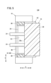
図10及び図11に示すように、人工心肺装置10Cは、可搬式の人工心肺本体12bと、人工心肺本体12bが着脱可能に形成された拡張ユニット14bとを備える。人工心肺本体12bは、ポンプユニット16aと、ポンプユニット16aが着脱可能に形成された駆動ユニット18bとを有する。ポンプユニット16aは、ポンプユニット16aの軸線方向(長手方向)が鉛直方向に沿うように(鉛直置きの状態で)駆動ユニット18bに装着される。10 and 11, the heart-
ポンプユニット16aは、上述したポンプユニット16と比較して、複数のポート部24の位置が異なっている。ポンプユニット16aにおいて、各ポート部24は、人工肺20の外周面から人工肺20の長手方向に沿って直線状に延出している。各ポート部24は、人工肺20の一端側に位置している。The
図11に示すように、駆動ユニット18bは、ポンプユニット16aを配置するための第1配置空間130と第1配置空間130にポンプユニット16aを挿入するための挿入口132とが形成された駆動ユニット本体134と、挿入口132を開閉する開閉部136とを備える。As shown in FIG. 11, the
駆動ユニット本体134は、人工肺20を支持する支持部138と、ポンプ22を駆動させるための駆動部44と、駆動部44を冷却する上述した冷却ファン46(図3参照)とを有する。The
支持部138は、U字状に形成されている。具体的に、支持部138は、一方向(図10の矢印X方向)に延在した支持部本体142と、支持部本体142の一端部(矢印X1方向の端部)に設けられた第1支持壁部144と、支持部本体142の他端部(矢印X2方向の端部)に設けられた第2支持壁部146とを有する。第1支持壁部144及び第2支持壁部146のそれぞれは、支持部本体142の上面よりも上方に延出している。第1支持壁部144と第2支持壁部146との間には、第1配置空間130が形成されている。The
支持部本体142の幅方向(矢印Y方向)の各側面には、係止突起148が設けられている。係止突起148は、金属板を90度に折り曲げたような形状を有する。係止突起148は、支持部本体142の幅方向外側に突出している。第1支持壁部144の支持部本体142とは反対側(矢印X1方向)の外面の両角部は、R形状に形成されている。A locking
図11及び図14Aに示すように、第1支持壁部144の矢印X1方向の外面には、第1穴150と、一対の第2穴152とが設けられている。第1穴150は、第1支持壁部144の下部に位置している。第1穴150は、第1支持壁部144の幅方向(矢印Y方向)の中央に位置している。第1穴150は、第1支持壁部144の幅方向に沿って長方形状に延在している。第1穴150の底面には、板状の第1端子部154が設けられている。
As shown in Figures 11 and 14A, a
一対の第2穴152は、第1穴150を矢印Y方向から挟むように位置している。各第2穴152は、円形状に形成されている。各第2穴152の内周面は、嵌合穴の開口部から底面に向かってテーパ状に縮径している(図14A参照)。The pair of
図11及び図12において、第2支持壁部146の支持部本体142とは反対側(矢印X2方向)の外面の両角部は、R形状に形成されている。第2支持壁部146の矢印X2方向の外面には、矢印X2方向に突出した突出部156が設けられている。突出部156は、第2支持壁部146の下部に位置している。突出部156は、支持部138の長手方向から見て四角形状に形成されている。突出部156は、第2支持壁部146の幅方向の中央に位置している。突出部156の第2支持壁部146とは反対側の外面には、突出部156の下端(矢印Z2方向の端)から上端(矢印Z1方向の端)に向かって第2支持壁部146側(矢印X1方向)に傾斜した第1テーパ面156aが形成されている。11 and 12, both corners of the outer surface of the
第2支持壁部146の上端面には、複数のポート部24が挿通する複数の挿通孔158が形成されている。各挿通孔158は、第2支持壁部146を矢印X方向に貫通するとともに第2支持壁部146の上面に開口している。A plurality of
図11において、駆動部44は、上述したインペラ28(図3参照)を回転させるためのモータ68を有する。モータ68は、軸部72が上下方向に沿うように支持部本体142の上面に設けられている。すなわち、モータ68の軸部72は、モータケース74から上方に延出している。モータケース74の上面には、第1配置空間130にポンプユニット16aが配置された状態で人工肺20の第2端面20bが対向する対向面76が設けられている。11, the
開閉部136は、挿入口132の全体を開閉するためのものである。開閉部136は、平板状に形成されている。開閉部136は、第1支持壁部144の上部にヒンジ160を介して開閉可能に設けられている。The opening/
開閉部136は、第1配置空間130にポンプユニット16aを配置するとともに挿入口132を閉じた状態で挿入口132から外部へのポンプユニット16aの移動を制限する。具体的に、開閉部136は、開閉部136の閉状態で、第1配置空間130に配置されたポンプユニット16aの第1端面20aに対向(接触又は近接)する。The opening/
図11及び図13に示すように、拡張ユニット14bは、一方向に延在して駆動ユニット18bを下方から支持するための底壁部162と、底壁部162の一端部(矢印X1方向の端部)に設けられた第1側壁部164と、底壁部162の他端部(矢印X2方向の端部)に設けられた第2側壁部166とを有する。第1側壁部164と第2側壁部166とは、矢印X方向に互いに対向する。第1側壁部164と第2側壁部166とは、底壁部162の上面よりも上方に延出している。第1側壁部164と第2側壁部166との間には、駆動ユニット18bが配置可能な第2配置空間168が設けられている。11 and 13, the
底壁部162の幅方向の各側面には、係止突起148を係止するための留め具170が設けられている。留め具170は、係止突起148の上面を下方に押さえ付けるための爪部172を有する。Each side surface of the
第1側壁部164のうち第2側壁部166側の壁面には、駆動ユニット18bの第1支持壁部144を鉛直方向に案内するための凹状の第1案内面174が形成されている。第1案内面174は、第1支持壁部144の矢印X1方向の外面形状に対応した形状を有する。第1案内面174は、横断面がU字状に形成されるとともに両角部がR形状に形成されている。A concave
図13及び図14Aに示すように、第1案内面174の下部には、押圧部材176を収容する収容穴178が形成されている。押圧部材176は、第2配置空間168に駆動ユニット18bが配置された状態で駆動ユニット18bを第2側壁部166側に押圧するためのものである。13 and 14A, a
押圧部材176は、第1側壁部164に対して底壁部162の長手方向に沿って移動可能なように収容穴178に配設されている。押圧部材176のうち第2側壁部166側の面には、中央凸部180と、一対の押圧突起182とが突出している。中央凸部180は、駆動ユニット18bを拡張ユニット14bに装着した状態で、駆動ユニット18bの第1穴150に挿入される。中央凸部180は、押圧部材176の矢印Y方向の中央に位置する。中央凸部180は、矢印Y方向に沿って長方形状に延在している。中央凸部180の突出端面には、中央凸部180が第1穴150に挿入された状態で第1端子部154に電気的に接続する第2端子部184が設けられている。The pressing
一対の押圧突起182のそれぞれは、駆動ユニット18bを拡張ユニット14bに装着した状態で、駆動ユニット18bの第2穴152のそれぞれに挿入される。一対の押圧突起182は、中央凸部180を矢印Y方向から挟むように位置している。各押圧突起182は、円錐台形状に形成されている。つまり、押圧突起182の外周面は、押圧突起182の押圧部材176側の根元から突出端までテーパ状に縮径している。押圧突起182のテーパ面は、第2穴152のテーパ面に当接する。Each of the pair of pressing
押圧部材176は、第1側壁部164に設けられた操作部186を回転操作することにより、矢印X方向に移動する。操作部186は、第1側壁部164の矢印Y方向の側面に設けられている。ただし、操作部186の配置は、適宜変更可能である。The pressing
第2側壁部166のうち第1側壁部164側の壁面には、駆動ユニット18bの第2支持壁部146を鉛直方向に案内するための凹状の第2案内面188が形成されている。第2案内面188は、第2側壁部166の矢印X2方向の外面形状に対応した形状を有する。第2案内面188は、横断面がU字状に形成されるとともに両角部がR形状に形成されている。A concave
第2側壁部166の下部には、駆動ユニット18bの突出部156が挿入可能な凹部190が形成されている。凹部190は、第2案内面188の矢印Y方向の中央に位置している。凹部190の底面は、溝部の下端から上端に向かって矢印X1方向に傾斜した第2テーパ面190aが形成されている。A
次に、人工心肺装置10Cの動作について説明する。Next, the operation of the heart-
ユーザは、駆動ユニット18bの開閉部136を開状態にし、ポンプユニット16aを挿入口132から第1配置空間130に下方に挿入する。これにより、人工肺20の第2端面20bが駆動ユニット本体134の対向面76に当接する。なお、ポンプユニット16aの複数のポート部24は、第2支持壁部146の挿通孔158に挿通される。The user opens the opening/
続いて、ユーザは、開閉部136を閉状態にする。これにより、挿入口132の全体が開閉部136によって閉じられる。つまり、人工肺20の第1端面20aは、開閉部136に対向する。以上の動作により、ポンプユニット16aと拡張ユニット14bとが一体的に組み込まれた人工心肺本体12bが得られる。Next, the user closes the opening/
その後、ユーザは、人工心肺本体12bを拡張ユニット14bに装着する。具体的に、ユーザは、駆動ユニット18bを拡張ユニット14bの第2配置空間168に下方に挿入する。この際、駆動ユニット18bの第1支持壁部144が第1案内面174によって下方に案内され、駆動ユニット18bの第2支持壁部146が第2案内面188によって下方に案内される。そして、駆動ユニット18bの底面が拡張ユニット14bの底壁部162の上面に当接すると、ユーザは、操作部186を回転操作する。そうすると、図14A及び図14Bに示すように、押圧部材176が矢印X2方向に移動し、中央凸部180が第1穴150に挿入されるとともに各押圧突起182が第2穴152に挿入される。
Then, the user attaches the heart-lung machine
そして、押圧部材176によって矢印X2方向に押された駆動ユニット18bは、第2側壁部166側に移動する。そのため、第2支持壁部146に設けられた突出部156が第2側壁部166の凹部190内に挿入される(図14B及び図15参照)。これにより、第1テーパ面156aと第2テーパ面190aとが互いに対向(接触又は近接)する。よって、拡張ユニット14bに対して駆動ユニット18bが上方に抜け出ることを抑えることができる。また、中央凸部180に設けられた第2端子部184が第1端子部154に対して電気的に接続される。
The
続いて、ユーザは、留め具170の爪部172により係止突起148を下方に押圧する。これにより駆動ユニット18bが拡張ユニット14bに固定される。以上の動作により、ポンプユニット16a、駆動ユニット18b及び拡張ユニット14bが一体的に組み込まれた人工心肺装置10Cが得られる。Next, the user presses the locking
本実施形態に係る人工心肺装置10Cは、以下の効果を奏する。The heart-
人工肺20は、筒状に形成され、駆動ユニット18bは、ポンプユニット16aが第1配置空間130に配置された状態で人工肺20の軸線が鉛直方向に沿って延在するように形成されている。The
このような構成によれば、ポンプユニット16aを鉛直配置(人工肺20の軸線が鉛直方向に沿うように配置)することができる。
With this configuration, the
人工心肺装置10Cは、駆動ユニット18bが着脱可能な拡張ユニット14bを備える。The heart-
このような構成によれば、ECMOを行う際に必要な機能を拡張することができる。 With this configuration, it is possible to expand the functions required when performing ECMO.
拡張ユニット14bは、一方向に延在して駆動ユニット18bを下方から支持するための底壁部162と、底壁部162の長手方向の両端部に互いに対向するように設けられた第1側壁部164及び第2側壁部166と、を有し、第1側壁部164と第2側壁部166との間には、駆動ユニット18bが配置される第2配置空間168が形成されている。The
このような構成によれば、駆動ユニット18bを拡張ユニット14bに装着する際に、第1側壁部164及び第2側壁部166によって駆動ユニット18bを第2配置空間168に案内することができる。
With this configuration, when the
第1側壁部164の内面には、駆動ユニット本体134の外面の形状に対応した形状の第1案内面174が形成され、第2側壁部166の内面には、駆動ユニット本体134の外面の形状に対応した形状の第2案内面188が形成されている。A
このような構成によれば、第1案内面174及び第2案内面188により、駆動ユニット18bを第2配置空間168に効果的に案内することができる。
With this configuration, the
拡張ユニット14bは、第2配置空間168に駆動ユニット18bが配置された状態で当該駆動ユニット18bを第2側壁部166側に押圧する押圧部材176を有し、押圧部材176は、第1案内面174に形成された収容穴178に底壁部162の長手方向に移動可能に配設されている。The
このような構成によれば、押圧部材176によって駆動ユニット18bを第2側壁部166に保持することができる。
With this configuration, the
押圧部材176には、第2側壁部166側に向かって突出した押圧突起182が設けられ、駆動ユニット18bには、押圧突起182が挿入される第2穴152が形成されている。The pressing
このような構成によれば、駆動ユニット18bを拡張ユニット14bに対して効果的に保持することができる。
With this configuration, the
押圧突起182は、突出方向にテーパ状に縮径され、第2穴152は、当該第2穴152の開口から底面に向かってテーパ状に縮径している。The
このような構成によれば、押圧突起182を第2穴152に挿入し易くすることができる。
This configuration makes it easier to insert the
本発明は上述した実施形態に限定されるものではなく、本発明の要旨を逸脱しない範囲において、種々の改変が可能である。The present invention is not limited to the above-described embodiments, and various modifications are possible without departing from the spirit and scope of the present invention.
人工心肺装置10A、10Bにおいて、第1端子部60及び第2端子部100は、1つずつ設けられてもよい。上述した実施形態において、ポンプユニット16、16aは、人工肺20とポンプ22とを備える。ただし、本発明に係る人工心肺装置のポンプユニットは、ポンプ22を備えるとともに人工肺20を備えないものであってもよい。In the artificial heart-
以上の実施形態をまとめると、以下のようになる。The above embodiments can be summarised as follows:
上記実施形態は、人工肺(20)と前記人工肺に血液を流通させるためのポンプ(22)とを有するポンプユニット(16、16a)と、前記ポンプを駆動させるための駆動部(44)を有するとともに前記ポンプユニットが着脱可能に形成された駆動ユニット(18、18a、18b)と、を備えた人工心肺装置(10A~10C)であって、前記駆動ユニットは、前記ポンプユニットを配置するための配置空間(32、130)と当該配置空間に前記ポンプユニットを挿入するための挿入口(34、132)とが形成された駆動ユニット本体(36、134)と、前記駆動ユニット本体に設けられて前記挿入口の少なくとも一部を開閉する開閉部(38、136)と、を有し、前記開閉部は、前記配置空間に前記ポンプユニットを配置するとともに前記挿入口の少なくとも一部を閉じた状態で前記挿入口から外部への前記ポンプユニットの移動を制限する、人工心肺装置を開示している。The above embodiment discloses an artificial heart-lung device (10A-10C) including a pump unit (16, 16a) having an artificial lung (20) and a pump (22) for circulating blood through the artificial lung, and a drive unit (18, 18a, 18b) having a drive section (44) for driving the pump and in which the pump unit is formed so as to be detachable, the drive unit having a drive unit body (36, 134) in which an arrangement space (32, 130) for arranging the pump unit and an insertion port (34, 132) for inserting the pump unit into the arrangement space are formed, and an opening/closing section (38, 136) provided on the drive unit body for opening and closing at least a portion of the insertion port, the opening/closing section disposing the pump unit in the arrangement space and restricting movement of the pump unit from the insertion port to the outside with at least a portion of the insertion port closed.
上記の人工心肺装置において、前記人工肺は、一方向に延在するとともに第1端面(20a)と第2端面(20b)とを有し、前記ポンプユニットを前記駆動ユニットに装着した状態で、前記第1端面が前記開閉部に対向するとともに前記第2端面が前記駆動ユニットに対向してもよい。In the above-mentioned artificial heart-lung device, the artificial lung extends in one direction and has a first end face (20a) and a second end face (20b), and when the pump unit is attached to the drive unit, the first end face faces the opening/closing portion and the second end face faces the drive unit.
上記の人工心肺装置において、前記ポンプは、回転可能なインペラ(28)と、前記ポンプユニットが前記駆動ユニットに装着された状態で、前記駆動ユニットの回転駆動力を前記インペラに伝達するための動力伝達部(30)と、を有してもよい。In the above-mentioned artificial heart-lung device, the pump may have a rotatable impeller (28) and a power transmission section (30) for transmitting the rotational driving force of the drive unit to the impeller when the pump unit is attached to the drive unit.
上記の人工心肺装置において、前記動力伝達部は、磁気カップリングであってもよい。In the above-mentioned artificial heart-lung device, the power transmission part may be a magnetic coupling.
上記の人工心肺装置において、前記人工肺には、前記第2端面に開口する内穴(26)が形成され、前記動力伝達部は、前記人工肺の前記内穴の底部に設けられ、前記駆動部は、前記インペラを回転させるためのモータ(68)を有し、前記モータの軸部(72)は、前記ポンプユニットが前記駆動ユニットに装着された状態で、前記人工肺の前記内穴に挿入されてもよい。In the above-mentioned artificial heart-lung device, the artificial lung has an inner hole (26) that opens to the second end face, the power transmission unit is provided at the bottom of the inner hole of the artificial lung, the drive unit has a motor (68) for rotating the impeller, and the shaft portion (72) of the motor may be inserted into the inner hole of the artificial lung with the pump unit attached to the drive unit.
上記の人工心肺装置において、前記駆動ユニットは、前記軸部に冷却風を供給するための冷却ファン(46)を有してもよい。In the above-mentioned artificial heart-lung machine, the drive unit may have a cooling fan (46) for supplying cooling air to the shaft portion.
上記の人工心肺装置において、前記人工肺は、筒状に形成され、前記駆動ユニットは、前記ポンプユニットが前記配置空間に配置された状態で前記人工肺の軸線が水平方向に沿って延在するように形成されてもよい。In the above-mentioned artificial heart-lung device, the artificial lung may be formed in a cylindrical shape, and the drive unit may be formed so that the axis of the artificial lung extends horizontally when the pump unit is disposed in the arrangement space.
上記の人工心肺装置において、前記駆動ユニット本体には、前記挿入口から前記配置空間への前記ポンプユニットの挿入を案内する案内面(52)が設けられてもよい。In the above-mentioned artificial heart-lung device, the drive unit body may be provided with a guide surface (52) for guiding the insertion of the pump unit from the insertion port into the arrangement space.
上記の人工心肺装置において、前記案内面は、前記配置空間の下方に位置するとともに前記人工肺の外周面の形状に対応した形状に形成されてもよい。In the above-mentioned artificial heart-lung device, the guide surface may be located below the arrangement space and formed into a shape corresponding to the shape of the outer peripheral surface of the artificial lung.
上記の人工心肺装置において、前記駆動ユニットは、前記開閉部を閉状態にロックするためのロック機構(86)を有してもよい。In the above-mentioned artificial heart-lung device, the drive unit may have a locking mechanism (86) for locking the opening and closing part in a closed state.
上記の人工心肺装置において、前記開閉部は、当該開閉部の閉状態で前記挿入口の少なくとも一部を閉じる開閉部本体(81)と、前記開閉部本体と前記駆動ユニット本体とを互いに連結するアーム部(82)と、を有し、前記アーム部は、前記駆動ユニット本体に対して傾動可能に設けられるとともにユーザによって把持可能に形成されてもよい。In the above-mentioned artificial heart-lung device, the opening/closing part has an opening/closing part main body (81) that closes at least a portion of the insertion opening when the opening/closing part is in a closed state, and an arm part (82) that connects the opening/closing part main body and the drive unit main body to each other, and the arm part may be tiltably arranged relative to the drive unit main body and formed so as to be grippable by a user.
上記の人工心肺装置において、前記人工心肺装置は、前記駆動ユニットが着脱可能な拡張ユニット(14、14a)を備えてもよい。In the above-mentioned heart-lung machine, the heart-lung machine may be provided with an expansion unit (14, 14a) to which the drive unit is detachable.
上記の人工心肺装置において、前記拡張ユニットは、一方向に延在して前記駆動ユニットを下方から支持するための底壁部(92)と、前記底壁部の幅方向の両側部から互いに対向するように上方に突出した一対の側壁部(94)と、を有してもよい。In the above-mentioned artificial heart-lung device, the expansion unit may have a bottom wall portion (92) extending in one direction to support the drive unit from below, and a pair of side wall portions (94) protruding upwardly from both widthwise sides of the bottom wall portion so as to face each other.
上記の人工心肺装置において、前記一対の側壁部のそれぞれの内面には、前記底壁部の長手方向に沿って延びたガイド溝(97)が形成され、前記ガイド溝の一端は、前記一対の側壁部のそれぞれの一端に開口し、前記駆動ユニットには、前記ガイド溝に案内される一対のスライド突起(56)が設けられてもよい。In the above-mentioned artificial heart-lung device, a guide groove (97) extending along the longitudinal direction of the bottom wall portion is formed on the inner surface of each of the pair of side wall portions, one end of the guide groove opens into one end of each of the pair of side wall portions, and the drive unit may be provided with a pair of slide protrusions (56) guided by the guide groove.
上記の人工心肺装置において、前記一対の側壁部のそれぞれは、前記底壁部の長手方向の一部に延在してもよい。In the above-mentioned heart-lung machine, each of the pair of side wall portions may extend along a portion of the longitudinal direction of the bottom wall portion.
上記の人工心肺装置において、前記一対の側壁部のそれぞれの内面には、前記ガイド溝の他端に連通する保持溝(98)が形成され、前記一対のスライド突起の少なくともいずれかには、第1端子部(60)が設けられ、前記保持溝の溝壁面のうち前記ガイド溝の一端側を指向する部位には、前記第1端子部に対して電気的に接続可能な第2端子部(100)が設けられてもよい。In the above-mentioned artificial heart-lung device, a retaining groove (98) communicating with the other end of the guide groove is formed on the inner surface of each of the pair of side wall portions, a first terminal portion (60) is provided on at least one of the pair of slide protrusions, and a second terminal portion (100) electrically connectable to the first terminal portion may be provided on a portion of the groove wall surface of the retaining groove that faces one end side of the guide groove.
上記の人工心肺装置において、前記底壁部の上面には、下方に凹状に窪んで前記駆動ユニットのスライド動作を案内する底壁案内面(96)が形成され、前記保持溝は、前記底壁案内面に開口してもよい。In the above-mentioned artificial heart-lung device, a bottom wall guide surface (96) is formed on the upper surface of the bottom wall portion so as to be concave downward and guide the sliding movement of the drive unit, and the retaining groove may open into the bottom wall guide surface.
上記の人工心肺装置において、前記底壁案内面は、横断面がU字状に形成されるとともに角部がR形状に形成されてもよい。In the above-mentioned artificial heart-lung device, the bottom wall guide surface may have a U-shaped cross section and an R-shaped corner.
上記の人工心肺装置において、前記底壁部には、前記駆動ユニットが前記拡張ユニットに装着された状態で、前記駆動ユニットの前記底壁部からの離脱を防止する離脱防止部(106、118)が設けられてもよい。In the above-mentioned artificial heart-lung device, the bottom wall portion may be provided with a detachment prevention portion (106, 118) that prevents the drive unit from detaching from the bottom wall portion when the drive unit is attached to the expansion unit.
上記の人工心肺装置において、前記離脱防止部は、前記底壁部の端面に回転可能に設けられた非円形状のストッパ部(124)を有し、前記ストッパ部は、当該ストッパ部の回転により、前記ストッパ部の一部が前記底壁部の上面よりも上方に突出する固定位置と当該ストッパ部の全体が底壁部の上面よりも下方に位置する解除位置とに切換可能であってもよい。In the above-mentioned artificial heart-lung machine, the detachment prevention portion may have a non-circular stopper portion (124) rotatably provided on the end surface of the bottom wall portion, and the stopper portion may be switchable, by rotation of the stopper portion, between a fixed position in which a part of the stopper portion protrudes above the upper surface of the bottom wall portion and a released position in which the entire stopper portion is positioned below the upper surface of the bottom wall portion.
上記の人工心肺装置において、前記拡張ユニットは、一方向に延在して前記駆動ユニットを下方から支持する底壁部(92)と、前記底壁部の幅方向の両側部から互いに対向するように上方に突出した一対の第1側壁部(114)及び一対の第2側壁部(116)と、を有し、前記一対の第1側壁部と前記一対の第2側壁部とは、前記底壁部の長手方向に互いに離間し、前記一対の第1側壁部のそれぞれの内面には、第1ガイド溝(120)が形成され、前記一対の第2側壁部のそれぞれの内面には、第2ガイド溝(122)が形成され、前記駆動ユニットには、前記第1ガイド溝に案内される一対の第1スライド突起(110)と、前記第2ガイド溝に案内される一対の第2スライド突起(112)と、が設けられてもよい。In the above-mentioned artificial heart-lung device, the expansion unit has a bottom wall portion (92) extending in one direction and supporting the drive unit from below, and a pair of first side wall portions (114) and a pair of second side wall portions (116) protruding upward from both sides in the width direction of the bottom wall portion so as to face each other, the pair of first side wall portions and the pair of second side wall portions are spaced apart from each other in the longitudinal direction of the bottom wall portion, a first guide groove (120) is formed on the inner surface of each of the pair of first side wall portions, and a second guide groove (122) is formed on the inner surface of each of the pair of second side wall portions, and the drive unit may be provided with a pair of first slide protrusions (110) guided by the first guide groove and a pair of second slide protrusions (112) guided by the second guide groove.
上記の人工心肺装置において、前記人工肺は、筒状に形成され、前記駆動ユニットは、前記ポンプユニットが前記配置空間に配置された状態で前記人工肺の軸線が鉛直方向に沿って延在するように形成されてもよい。In the above-mentioned artificial heart-lung device, the artificial lung may be formed in a cylindrical shape, and the drive unit may be formed so that the axis of the artificial lung extends vertically when the pump unit is placed in the arrangement space.
上記の人工心肺装置において、前記人工心肺装置は、前記駆動ユニットが着脱可能な拡張ユニット(14b)を備えてもよい。In the above-mentioned heart-lung machine, the heart-lung machine may be provided with an expansion unit (14b) to which the drive unit is detachable.
上記の人工心肺装置において、前記拡張ユニットは、一方向に延在して前記駆動ユニットを下方から支持するための底壁部(162)と、前記底壁部の長手方向の両端部に互いに対向するように設けられた第1側壁部(164)及び第2側壁部(166)と、を有し、前記配置空間は、第1配置空間(130)であり、前記第1側壁部と前記第2側壁部との間には、前記駆動ユニットが配置される第2配置空間(168)が形成されてもよい。In the above-mentioned artificial heart-lung device, the expansion unit has a bottom wall portion (162) extending in one direction for supporting the drive unit from below, and a first side wall portion (164) and a second side wall portion (166) arranged opposite each other at both longitudinal ends of the bottom wall portion, and the arrangement space is a first arrangement space (130), and a second arrangement space (168) in which the drive unit is arranged may be formed between the first side wall portion and the second side wall portion.
上記の人工心肺装置において、前記第1側壁部の内面には、前記駆動ユニット本体の外面の形状に対応した形状の第1案内面(174)が形成され、前記第2側壁部の内面には、前記駆動ユニット本体の外面の形状に対応した形状の第2案内面(188)が形成されてもよい。In the above-mentioned artificial heart-lung device, a first guide surface (174) having a shape corresponding to the shape of the outer surface of the drive unit body may be formed on the inner surface of the first side wall portion, and a second guide surface (188) having a shape corresponding to the shape of the outer surface of the drive unit body may be formed on the inner surface of the second side wall portion.
上記の人工心肺装置において、前記拡張ユニットは、前記第2配置空間に前記駆動ユニットが配置された状態で当該駆動ユニットを前記第2側壁部側に押圧する押圧部材(176)を有し、前記押圧部材は、前記第1案内面に形成された収容穴(178)に前記底壁部の長手方向に移動可能に配設されてもよい。In the above-mentioned artificial heart-lung device, the expansion unit has a pressing member (176) that presses the drive unit toward the second side wall portion when the drive unit is placed in the second placement space, and the pressing member may be arranged in an accommodation hole (178) formed in the first guide surface so as to be movable in the longitudinal direction of the bottom wall portion.
上記の人工心肺装置において、前記押圧部材には、前記第2側壁部側に向かって突出した押圧突起(182)が設けられ、前記駆動ユニットには、前記押圧突起が挿入される穴(152)が形成されてもよい。In the above-mentioned artificial heart-lung device, the pressing member may be provided with a pressing protrusion (182) protruding toward the second side wall portion, and the drive unit may be formed with a hole (152) into which the pressing protrusion is inserted.
上記の人工心肺装置において、前記押圧突起は、突出方向にテーパ状に縮径され、前記穴は、当該穴の開口から底面に向かってテーパ状に縮径してもよい。In the above-mentioned artificial heart-lung device, the pressure projection may be tapered in diameter in the protruding direction, and the hole may be tapered in diameter from the opening of the hole toward the bottom surface.
上記実施形態は、人工肺に血液を流通させるためのポンプを有するポンプユニットと、前記ポンプを駆動させるための駆動部を有するとともに前記ポンプユニットが着脱可能に形成された駆動ユニットと、を備えた人工心肺装置であって、前記駆動ユニットは、前記ポンプユニットを配置するための配置空間と当該配置空間に前記ポンプユニットを挿入するための挿入口とが形成された駆動ユニット本体と、前記駆動ユニット本体に設けられて前記挿入口の少なくとも一部を開閉する開閉部と、を有し、前記開閉部は、前記配置空間に前記ポンプユニットを配置するとともに前記挿入口の少なくとも一部を閉じた状態で前記挿入口から外部への前記ポンプユニットの移動を制限する、人工心肺装置を開示している。The above embodiment discloses an artificial heart-lung device comprising a pump unit having a pump for circulating blood through an artificial lung, and a drive unit having a drive part for driving the pump and in which the pump unit is formed so as to be detachable, the drive unit having a drive unit body in which an arrangement space for placing the pump unit and an insertion port for inserting the pump unit into the arrangement space are formed, and an opening/closing part provided on the drive unit body for opening and closing at least a portion of the insertion port, the opening/closing part placing the pump unit in the arrangement space and restricting movement of the pump unit from the insertion port to the outside with at least a portion of the insertion port closed.
Claims (29)
前記駆動ユニットは、
前記ポンプユニットを配置するための配置空間と当該配置空間に前記ポンプユニットを挿入するための挿入口とが形成された駆動ユニット本体と、
前記駆動ユニット本体に設けられて前記挿入口の少なくとも一部を開閉する開閉部と、を有し、
前記開閉部は、前記配置空間に前記ポンプユニットを配置するとともに前記挿入口の少なくとも一部を閉じた状態で前記挿入口から外部への前記ポンプユニットの移動を制限する、人工心肺装置。 An artificial heart-lung device comprising: a pump unit having an artificial lung and a pump for circulating blood through the artificial lung; and a drive unit having a drive section for driving the pump and having the pump unit formed so as to be detachable,
The drive unit includes:
a drive unit body having an arrangement space for arranging the pump unit and an insertion port for inserting the pump unit into the arrangement space;
an opening/closing section provided in the drive unit body for opening and closing at least a portion of the insertion opening,
The opening/closing section places the pump unit in the placement space and restricts movement of the pump unit from the insertion opening to the outside while closing at least a portion of the insertion opening.
前記人工肺は、一方向に延在するとともに第1端面と第2端面とを有し、
前記ポンプユニットを前記駆動ユニットに装着した状態で、前記第1端面が前記開閉部に対向するとともに前記第2端面が前記駆動ユニットに対向する、人工心肺装置。 2. The heart-lung machine of claim 1,
The oxygenator extends in one direction and has a first end surface and a second end surface,
the first end surface faces the opening/closing portion and the second end surface faces the drive unit when the pump unit is attached to the drive unit.
前記ポンプは、
回転可能なインペラと、
前記ポンプユニットが前記駆動ユニットに装着された状態で、前記駆動ユニットの回転駆動力を前記インペラに伝達するための動力伝達部と、を有する、人工心肺装置。 3. The heart-lung machine according to claim 2,
The pump comprises:
A rotatable impeller;
a power transmission section for transmitting the rotational driving force of the drive unit to the impeller when the pump unit is attached to the drive unit.
前記動力伝達部は、磁気カップリングである、人工心肺装置。 4. The heart-lung machine of claim 3,
The power transmission unit is a magnetic coupling.
前記人工肺には、前記第2端面に開口する内穴が形成され、
前記動力伝達部は、前記人工肺の前記内穴の底部に設けられ、
前記駆動部は、前記インペラを回転させるためのモータを有し、
前記モータの軸部は、前記ポンプユニットが前記駆動ユニットに装着された状態で、前記人工肺の前記内穴に挿入される、人工心肺装置。 5. The heart-lung machine according to claim 3,
The oxygenator has an inner hole that opens to the second end surface,
The power transmission unit is provided at the bottom of the inner lumen of the oxygenator,
The drive unit has a motor for rotating the impeller,
An artificial heart-lung device, wherein the shaft portion of the motor is inserted into the inner lumen of the artificial lung with the pump unit attached to the drive unit.
前記駆動ユニットは、前記軸部に冷却風を供給するための冷却ファンを有する、人工心肺装置。 6. The heart-lung machine of claim 5,
The drive unit has a cooling fan for supplying cooling air to the shaft portion.
前記人工肺は、筒状に形成され、
前記駆動ユニットは、前記ポンプユニットが前記配置空間に配置された状態で前記人工肺の軸線が水平方向に沿って延在するように形成されている、人工心肺装置。 The heart-lung machine according to any one of claims 1 to 6,
The oxygenator is formed in a cylindrical shape,
The drive unit is formed so that the axis of the oxygenator extends horizontally when the pump unit is disposed in the arrangement space.
前記駆動ユニット本体には、前記挿入口から前記配置空間への前記ポンプユニットの挿入を案内する案内面が設けられている、人工心肺装置。 8. The heart-lung machine of claim 7,
The drive unit body is provided with a guide surface that guides the insertion of the pump unit from the insertion opening into the arrangement space.
前記案内面は、前記配置空間の下方に位置するとともに前記人工肺の外周面の形状に対応した形状に形成されている、人工心肺装置。 9. The heart-lung machine of claim 8,
An artificial heart-lung device, wherein the guide surface is located below the arrangement space and is formed into a shape corresponding to the shape of the outer peripheral surface of the artificial lung.
前記駆動ユニットは、前記開閉部を閉状態にロックするためのロック機構を有している、人工心肺装置。 The heart-lung machine according to any one of claims 7 to 9,
The drive unit has a locking mechanism for locking the opening/closing part in a closed state.
前記開閉部は、
当該開閉部の閉状態で前記挿入口の少なくとも一部を閉じる開閉部本体と、
前記開閉部本体と前記駆動ユニット本体とを互いに連結するアーム部と、を有し、
前記アーム部は、前記駆動ユニット本体に対して傾動可能に設けられるとともにユーザによって把持可能に形成されている、人工心肺装置。 11. The heart-lung machine of claim 10,
The opening and closing portion is
an opening/closing unit main body that closes at least a portion of the insertion opening when the opening/closing unit is in a closed state;
an arm portion that connects the opening/closing portion main body and the drive unit main body to each other,
The arm portion is tiltably provided with respect to the drive unit body and is configured to be grippable by a user.
前記人工心肺装置は、前記駆動ユニットが着脱可能な拡張ユニットを備える、人工心肺装置。 The heart-lung machine according to any one of claims 7 to 11,
The heart-lung machine includes an expansion unit to which the drive unit is detachable.
前記拡張ユニットは、
一方向に延在して前記駆動ユニットを下方から支持するための底壁部と、
前記底壁部の幅方向の両側部から互いに対向するように上方に突出した一対の側壁部と、を有する、人工心肺装置。 13. The heart-lung machine of claim 12,
The expansion unit includes:
a bottom wall portion extending in one direction to support the drive unit from below;
a pair of side walls protruding upwardly from both sides in the width direction of the bottom wall so as to face each other,
前記一対の側壁部のそれぞれの内面には、前記底壁部の長手方向に沿って延びたガイド溝が形成され、
前記ガイド溝の一端は、前記一対の側壁部のそれぞれの一端に開口し、
前記駆動ユニットには、前記ガイド溝に案内される一対のスライド突起が設けられている、人工心肺装置。 14. The heart-lung machine of claim 13,
A guide groove is formed on each inner surface of the pair of side walls, the guide groove extending along the longitudinal direction of the bottom wall,
One end of the guide groove opens to one end of each of the pair of side wall portions,
The drive unit is provided with a pair of slide protrusions that are guided by the guide grooves.
前記一対の側壁部のそれぞれは、前記底壁部の長手方向の一部に延在している、人工心肺装置。 15. The heart-lung machine of claim 14,
An artificial heart-lung machine, wherein each of the pair of side wall portions extends along a portion of the longitudinal direction of the bottom wall portion.
前記一対の側壁部のそれぞれの内面には、前記ガイド溝の他端に連通する保持溝が形成され、
前記一対のスライド突起の少なくともいずれかには、第1端子部が設けられ、
前記保持溝の溝壁面のうち前記ガイド溝の一端側を指向する部位には、前記第1端子部に対して電気的に接続可能な第2端子部が設けられている、人工心肺装置。 16. The heart-lung machine according to claim 14 or 15,
A holding groove is formed on an inner surface of each of the pair of side walls, the holding groove being connected to the other end of the guide groove,
At least one of the pair of slide protrusions is provided with a first terminal portion,
An artificial heart-lung machine, wherein a second terminal portion electrically connectable to the first terminal portion is provided on a portion of the groove wall surface of the holding groove that faces one end side of the guide groove.
前記底壁部の上面には、下方に凹状に窪んで前記駆動ユニットのスライド動作を案内する底壁案内面が形成され、
前記保持溝は、前記底壁案内面に開口している、人工心肺装置。 17. The heart-lung machine of claim 16,
a bottom wall guide surface that is recessed downward and guides the sliding movement of the drive unit is formed on an upper surface of the bottom wall portion;
The retaining groove opens into the bottom wall guide surface.
前記底壁案内面は、横断面がU字状に形成されるとともに角部がR形状に形成されている、人工心肺装置。 18. The heart-lung machine of claim 17,
In the heart-lung machine, the bottom wall guide surface has a U-shaped cross section and has R-shaped corners.
前記底壁部には、前記駆動ユニットが前記拡張ユニットに装着された状態で、前記駆動ユニットの前記底壁部からの離脱を防止する離脱防止部が設けられている、人工心肺装置。 The heart-lung machine according to any one of claims 13 to 18,
The bottom wall portion is provided with a detachment prevention portion that prevents the drive unit from detaching from the bottom wall portion when the drive unit is attached to the expansion unit, in the artificial heart-lung device.
前記離脱防止部は、前記底壁部の端面に回転可能に設けられた非円形状のストッパ部を有し、
前記ストッパ部は、当該ストッパ部の回転により、前記ストッパ部の一部が前記底壁部の上面よりも上方に突出する固定位置と当該ストッパ部の全体が底壁部の上面よりも下方に位置する解除位置とに切換可能である、人工心肺装置。 20. The heart-lung machine of claim 19,
The separation prevention portion has a non-circular stopper portion rotatably provided on an end surface of the bottom wall portion,
The stopper portion can be switched, by rotating the stopper portion, between a fixed position in which a portion of the stopper portion protrudes above the upper surface of the bottom wall portion and a released position in which the entire stopper portion is positioned below the upper surface of the bottom wall portion.
前記拡張ユニットは、
一方向に延在して前記駆動ユニットを下方から支持する底壁部と、
前記底壁部の幅方向の両側部から互いに対向するように上方に突出した一対の第1側壁部及び一対の第2側壁部と、を有し、
前記一対の第1側壁部と前記一対の第2側壁部とは、前記底壁部の長手方向に互いに離間し、
前記一対の第1側壁部のそれぞれの内面には、第1ガイド溝が形成され、
前記一対の第2側壁部のそれぞれの内面には、第2ガイド溝が形成され、
前記駆動ユニットには、
前記第1ガイド溝に案内される一対の第1スライド突起と、
前記第2ガイド溝に案内される一対の第2スライド突起と、が設けられている、人工心肺装置。 13. The heart-lung machine of claim 12,
The expansion unit includes:
a bottom wall portion extending in one direction and supporting the drive unit from below;
a pair of first side wall portions and a pair of second side wall portions protruding upward from both sides in a width direction of the bottom wall portion so as to face each other;
The pair of first side wall portions and the pair of second side wall portions are spaced apart from each other in a longitudinal direction of the bottom wall portion,
A first guide groove is formed on each inner surface of the pair of first side wall portions,
A second guide groove is formed on each inner surface of the pair of second side walls,
The drive unit includes:
a pair of first slide protrusions guided by the first guide grooves;
a pair of second slide protrusions guided by the second guide grooves.
前記人工肺は、筒状に形成され、
前記駆動ユニットは、前記ポンプユニットが前記配置空間に配置された状態で前記人工肺の軸線が鉛直方向に沿って延在するように形成されている、人工心肺装置。 The heart-lung machine according to any one of claims 1 to 6,
The oxygenator is formed in a cylindrical shape,
The drive unit is formed so that the axis of the oxygenator extends vertically when the pump unit is disposed in the arrangement space.
前記人工心肺装置は、前記駆動ユニットが着脱可能な拡張ユニットを備える、人工心肺装置。 23. The heart-lung machine of claim 22,
The heart-lung machine includes an expansion unit to which the drive unit is detachable.
前記拡張ユニットは、
一方向に延在して前記駆動ユニットを下方から支持するための底壁部と、
前記底壁部の長手方向の両端部に互いに対向するように設けられた第1側壁部及び第2側壁部と、を有し、
前記配置空間は、第1配置空間であり、
前記第1側壁部と前記第2側壁部との間には、前記駆動ユニットが配置される第2配置空間が形成されている、人工心肺装置。 24. The heart-lung machine of claim 23,
The expansion unit includes:
a bottom wall portion extending in one direction to support the drive unit from below;
a first side wall portion and a second side wall portion provided opposite each other at both longitudinal ends of the bottom wall portion,
The arrangement space is a first arrangement space,
The heart-lung machine has a second arrangement space formed between the first side wall portion and the second side wall portion, in which the drive unit is arranged.
前記第1側壁部の内面には、前記駆動ユニット本体の外面の形状に対応した形状の第1案内面が形成され、
前記第2側壁部の内面には、前記駆動ユニット本体の外面の形状に対応した形状の第2案内面が形成されている、人工心肺装置。 25. The heart-lung machine of claim 24,
a first guide surface having a shape corresponding to a shape of an outer surface of the drive unit body is formed on an inner surface of the first side wall portion;
an inner surface of the second side wall portion is formed with a second guide surface having a shape corresponding to a shape of an outer surface of the drive unit body;
前記拡張ユニットは、前記第2配置空間に前記駆動ユニットが配置された状態で当該駆動ユニットを前記第2側壁部側に押圧する押圧部材を有し、
前記押圧部材は、前記第1案内面に形成された収容穴に前記底壁部の長手方向に移動可能に配設されている、人工心肺装置。 26. The heart-lung machine of claim 25,
the extension unit has a pressing member that presses the drive unit toward the second side wall portion when the drive unit is disposed in the second arrangement space,
The pressing member is disposed in an accommodation hole formed in the first guide surface so as to be movable in the longitudinal direction of the bottom wall portion.
前記押圧部材には、前記第2側壁部側に向かって突出した押圧突起が設けられ、
前記駆動ユニットには、前記押圧突起が挿入される穴が形成されている、人工心肺装置。 27. The heart-lung machine of claim 26,
The pressing member is provided with a pressing protrusion protruding toward the second side wall portion,
The drive unit has a hole into which the pressing protrusion is inserted.
前記押圧突起は、突出方向にテーパ状に縮径され、
前記穴は、当該穴の開口から底面に向かってテーパ状に縮径している、人工心肺装置。 28. The heart-lung machine of claim 27,
The pressing protrusion is tapered in a protruding direction,
The hole has a tapered diameter from an opening of the hole toward a bottom surface of the hole.
前記駆動ユニットは、
前記ポンプユニットを配置するための配置空間と当該配置空間に前記ポンプユニットを挿入するための挿入口とが形成された駆動ユニット本体と、
前記駆動ユニット本体に設けられて前記挿入口の少なくとも一部を開閉する開閉部と、を有し、
前記開閉部は、前記配置空間に前記ポンプユニットを配置するとともに前記挿入口の少なくとも一部を閉じた状態で前記挿入口から外部への前記ポンプユニットの移動を制限する、人工心肺装置。 An artificial heart-lung device comprising: a pump unit having a pump for circulating blood through an artificial lung; and a drive unit having a drive section for driving the pump and to which the pump unit is detachably formed,
The drive unit includes:
a drive unit body having an arrangement space for arranging the pump unit and an insertion port for inserting the pump unit into the arrangement space;
an opening/closing section provided in the drive unit body for opening and closing at least a portion of the insertion opening,
The opening/closing section places the pump unit in the placement space and restricts movement of the pump unit from the insertion opening to the outside while closing at least a portion of the insertion opening.
Applications Claiming Priority (3)
| Application Number | Priority Date | Filing Date | Title |
|---|---|---|---|
| JP2020035753 | 2020-03-03 | ||
| JP2020035753 | 2020-03-03 | ||
| PCT/JP2021/007115 WO2021177136A1 (en) | 2020-03-03 | 2021-02-25 | Artificial cardiopulmonary device |
Publications (2)
| Publication Number | Publication Date |
|---|---|
| JPWO2021177136A1 JPWO2021177136A1 (en) | 2021-09-10 |
| JP7581321B2 true JP7581321B2 (en) | 2024-11-12 |
Family
ID=77613050
Family Applications (1)
| Application Number | Title | Priority Date | Filing Date |
|---|---|---|---|
| JP2022505156A Active JP7581321B2 (en) | 2020-03-03 | 2021-02-25 | Heart-lung machine |
Country Status (2)
| Country | Link |
|---|---|
| JP (1) | JP7581321B2 (en) |
| WO (1) | WO2021177136A1 (en) |
Citations (6)
| Publication number | Priority date | Publication date | Assignee | Title |
|---|---|---|---|---|
| JP2002536126A (en) | 1999-02-12 | 2002-10-29 | ライフブリッジ メディツィンテクニーク ゲゼルシャフト ミット ベシュレンクテル ハフツング | Mobile heart-lung machine |
| JP2006142031A (en) | 2004-11-24 | 2006-06-08 | Lifebridge Medizintechnik Gmbh | Extracorporeal blood circulating apparatus |
| JP2010227154A (en) | 2009-03-25 | 2010-10-14 | Terumo Corp | Artificial lung holder |
| US20130226064A1 (en) | 2010-11-05 | 2013-08-29 | Rand S.R.L. | Portable medical apparatus for cardiopulmonary aid to patients |
| JP2014046026A (en) | 2012-08-31 | 2014-03-17 | Kyocera Medical Corp | Driving device for artificial heart lung pump |
| JP2019005036A (en) | 2017-06-22 | 2019-01-17 | 株式会社ジェイ・エム・エス | Artificial cardiopulmonary pump drive |
-
2021
- 2021-02-25 JP JP2022505156A patent/JP7581321B2/en active Active
- 2021-02-25 WO PCT/JP2021/007115 patent/WO2021177136A1/en not_active Ceased
Patent Citations (6)
| Publication number | Priority date | Publication date | Assignee | Title |
|---|---|---|---|---|
| JP2002536126A (en) | 1999-02-12 | 2002-10-29 | ライフブリッジ メディツィンテクニーク ゲゼルシャフト ミット ベシュレンクテル ハフツング | Mobile heart-lung machine |
| JP2006142031A (en) | 2004-11-24 | 2006-06-08 | Lifebridge Medizintechnik Gmbh | Extracorporeal blood circulating apparatus |
| JP2010227154A (en) | 2009-03-25 | 2010-10-14 | Terumo Corp | Artificial lung holder |
| US20130226064A1 (en) | 2010-11-05 | 2013-08-29 | Rand S.R.L. | Portable medical apparatus for cardiopulmonary aid to patients |
| JP2014046026A (en) | 2012-08-31 | 2014-03-17 | Kyocera Medical Corp | Driving device for artificial heart lung pump |
| JP2019005036A (en) | 2017-06-22 | 2019-01-17 | 株式会社ジェイ・エム・エス | Artificial cardiopulmonary pump drive |
Also Published As
| Publication number | Publication date |
|---|---|
| JPWO2021177136A1 (en) | 2021-09-10 |
| WO2021177136A1 (en) | 2021-09-10 |
Similar Documents
| Publication | Publication Date | Title |
|---|---|---|
| CN111542352B (en) | Easy to move blood purification system | |
| JPH01501207A (en) | surgical bone drilling machine | |
| JP2000041795A (en) | Rotary type mattress for baby | |
| JP7581321B2 (en) | Heart-lung machine | |
| JP2006501000A (en) | Dialysis machine with combined display and handle | |
| WO2008118719A1 (en) | Laryngoscope blade | |
| CN104120588A (en) | Door assembly and clothes treatment apparatus having same | |
| TWI763303B (en) | Tool arrangement and method for managing tool elements by the tool arrangement | |
| EP1142598B1 (en) | Intraoperative autotransfusion device | |
| WO2014059892A1 (en) | Valve positioning structure | |
| JP4587531B2 (en) | Incubator | |
| JP2008178444A (en) | Roller pump | |
| JP2002028199A (en) | Incubator | |
| JP2810349B2 (en) | Microwave oven turntable moving device | |
| CN217285701U (en) | Endoscope switching device | |
| JP6164482B2 (en) | Medical device connection structure | |
| JP4660847B2 (en) | Roller pump | |
| JP3918092B2 (en) | Tube pump | |
| CN218280930U (en) | Quick clamping mechanism of filter | |
| CN217426579U (en) | Switch starting structure and hair-dryer | |
| CN113082443B (en) | Lid opening/closing member, container lid, container body, container device, and ventilation therapy device | |
| CN219440422U (en) | A Microcomputer Pulse Therapeutic Apparatus | |
| JP3409324B2 (en) | Medical fluid flow switching device | |
| JP5682399B2 (en) | Artificial lung holder | |
| JP4192161B2 (en) | Tube pump |
Legal Events
| Date | Code | Title | Description |
|---|---|---|---|
| A621 | Written request for application examination |
Free format text: JAPANESE INTERMEDIATE CODE: A621 Effective date: 20231013 |
|
| TRDD | Decision of grant or rejection written | ||
| A01 | Written decision to grant a patent or to grant a registration (utility model) |
Free format text: JAPANESE INTERMEDIATE CODE: A01 Effective date: 20241001 |
|
| A61 | First payment of annual fees (during grant procedure) |
Free format text: JAPANESE INTERMEDIATE CODE: A61 Effective date: 20241030 |
|
| R150 | Certificate of patent or registration of utility model |
Ref document number: 7581321 Country of ref document: JP Free format text: JAPANESE INTERMEDIATE CODE: R150 |