JP7580098B1 - Tools for electric wires and methods for working with electric wires - Google Patents

Tools for electric wires and methods for working with electric wires Download PDF

Info

Publication number
JP7580098B1
JP7580098B1 JP2024101629A JP2024101629A JP7580098B1 JP 7580098 B1 JP7580098 B1 JP 7580098B1 JP 2024101629 A JP2024101629 A JP 2024101629A JP 2024101629 A JP2024101629 A JP 2024101629A JP 7580098 B1 JP7580098 B1 JP 7580098B1
Authority
JP
Japan
Prior art keywords
core material
holding
holding portion
electric wire
wire
Prior art date
Legal status (The legal status is an assumption and is not a legal conclusion. Google has not performed a legal analysis and makes no representation as to the accuracy of the status listed.)
Active
Application number
JP2024101629A
Other languages
Japanese (ja)
Other versions
JP2026003646A (en
Inventor
広治 三浦
景尚 松木
健司 鈴木
友也 安倍
Original Assignee
株式会社ユアテック
日本安全産業株式会社
Priority date (The priority date is an assumption and is not a legal conclusion. Google has not performed a legal analysis and makes no representation as to the accuracy of the date listed.)
Filing date
Publication date
Application filed by 株式会社ユアテック, 日本安全産業株式会社 filed Critical 株式会社ユアテック
Priority to JP2024101629A priority Critical patent/JP7580098B1/en
Application granted granted Critical
Publication of JP7580098B1 publication Critical patent/JP7580098B1/en
Publication of JP2026003646A publication Critical patent/JP2026003646A/en
Active legal-status Critical Current
Anticipated expiration legal-status Critical

Links

Images

Landscapes

  • Electric Cable Installation (AREA)

Abstract

Figure 0007580098000001

【課題】操作性および安全性に優れた電線用工具および電線作業方法を提供すること。
【解決手段】電線用工具1は、電線を切断または接続する際に使用する電線用工具であって、長尺な芯材2と、芯材2に配置され、電線を保持する第1保持部3Aと、芯材2に第1保持部3Aと離間して配置され、電線を保持する第2保持部3Bと、を有する。そして、芯材2は、第1保持部3Aと第2保持部3Bとの間の少なくとも一部の領域において可撓変形し、かつ、可撓変形後の形状を維持することができる。
【選択図】図2

Figure 0007580098000001

The present invention provides a tool for electric wires and a method for working with electric wires that are easy to operate and safe.
[Solution] The electric wire tool 1 is an electric wire tool used when cutting or connecting an electric wire, and has a long core material 2, a first holding portion 3A arranged on the core material 2 and holding the electric wire, and a second holding portion 3B arranged on the core material 2 and spaced apart from the first holding portion 3A and holding the electric wire. The core material 2 is capable of flexibly deforming in at least a partial region between the first holding portion 3A and the second holding portion 3B, and maintaining the shape after the flexibly deformation.
[Selected figure] Figure 2

Description

本発明は、電線用工具および電線作業方法に関する。 The present invention relates to a tool for electric wires and a method for working with electric wires.

例えば、特許文献1には、電線の切断および再接続時に用いられる高圧引下線用切断補助具が記載されている。高圧引下線用切断補助具は、第1管体および第1管体に対してスライド可能な第2管体を備える管体と、第1管体に設けられ引下線を把持する第1クリップと、第2管体に設けられ引下線を把持する第2クリップと、を有する。このような高圧引下線用切断補助具は、次のようにして使用する。まず、管体を収縮させた状態で高圧引下線を第1、第2クリップで把持する。次に、高圧引下線を第1、第2クリップで把持された2か所の間で切断する。すると、管体が自重によって予め定めた長さまで自然に伸長する。これにより、高圧引下線の端末同士が離間する。 For example, Patent Document 1 describes a cutting aid for high-voltage down-line used when cutting and reconnecting electric wires. The cutting aid for high-voltage down-line has a tube body with a first tube body and a second tube body that can slide relative to the first tube body, a first clip that is provided on the first tube body and holds the down-line, and a second clip that is provided on the second tube body and holds the down-line. Such a cutting aid for high-voltage down-line is used as follows. First, the high-voltage down-line is held by the first and second clips while the tube body is contracted. Next, the high-voltage down-line is cut between the two points held by the first and second clips. Then, the tube body naturally extends to a predetermined length due to its own weight. This causes the ends of the high-voltage down-line to separate from each other.

特開2018-074826号公報JP 2018-074826 A

しかしながら、特許文献1の高圧引下線用切断補助具では、使用する際に予め管体を収縮させ、かつ、伸長時の管体の長さを定めておかなければならず、使い勝手が悪い。さらには、特許文献1の高圧引下線用切断補助具では、管体の伸長によって第1、第2クリップを離間させることができても、第1、第2クリップの相対的な向きを変化させることができない。そのため、高圧引下線の端末同士が向かい合った状態が維持され、高い安全性を確保することが困難でもある。 However, with the high-voltage downline cutting aid of Patent Document 1, the tube must be contracted before use and the length of the tube when extended must be determined, making it difficult to use. Furthermore, with the high-voltage downline cutting aid of Patent Document 1, although the first and second clips can be separated by extending the tube, the relative orientation of the first and second clips cannot be changed. As a result, the ends of the high-voltage downline remain facing each other, making it difficult to ensure high safety.

本発明の目的は、上述の問題点に鑑みてなされたものであり、操作性に優れ、かつ、高い安全性を有する電線用工具および当該電線用工具を用いた安全性の高い電線作業方法を提供することにある。 The object of the present invention, which has been made in consideration of the above-mentioned problems, is to provide a tool for electric wires that is easy to operate and has a high level of safety, and a method for working with electric wires that uses the tool for electric wires and is therefore highly safe.

このような目的は、下記の本発明により達成される。 This objective is achieved by the present invention described below.

(1) 電線を切断または接続する際に使用する電線用工具であって、
長尺な芯材と、
前記芯材に配置され、前記電線を保持する第1保持部と、
前記芯材に前記第1保持部と離間して配置され、前記電線を保持する第2保持部と、を有し、
前記芯材は、前記第1保持部と前記第2保持部との間の少なくとも一部の領域において可撓変形し、かつ、前記可撓変形後の形状を維持することができることを特徴とする電線用工具。
(1) A tool for cutting or connecting electric wires,
A long core material,
A first holding portion that is disposed on the core material and holds the electric wire;
a second holding portion disposed on the core material and spaced apart from the first holding portion and holding the electric wire;
The core material is capable of flexibly deforming in at least a portion of the region between the first holding portion and the second holding portion, and of maintaining the shape after the flexibly deforming.

(2) 前記第1保持部および前記第2保持部は、それぞれ、前記芯材に対して前記芯材の中心軸まわりに回転可能である上記(1)に記載の電線用工具。 (2) The wire tool according to (1) above, in which the first holding part and the second holding part are each rotatable around the central axis of the core material relative to the core material.

(3) 前記第1保持部および前記第2保持部は、前記芯材に対して前記芯材の長手方向における位置が固定されている上記(1)に記載の電線用工具。 (3) The wire tool according to (1) above, in which the first holding portion and the second holding portion are fixed in position relative to the core material in the longitudinal direction of the core material.

(4) 前記芯材は、金属製である上記(1)に記載の電線用工具。 (4) The wire tool according to (1) above, in which the core material is made of metal.

(5) 前記芯材を被覆する絶縁性の保護被覆を有する上記(4)に記載の電線用工具。 (5) The wire tool described in (4) above, which has an insulating protective coating that covers the core material.

(6) 前記第1保持部および前記第2保持部は、それぞれ、前記電線を把持するクリップである上記(1)に記載の電線用工具。 (6) The electric wire tool described in (1) above, in which the first holding part and the second holding part are each a clip that grips the electric wire.

(7) 前記クリップは、前記芯材の中心軸まわりに開閉する一対の保持アームを有する上記(6)に記載の電線用工具。 (7) The wire tool described in (6) above, in which the clip has a pair of holding arms that open and close around the central axis of the core material.

(8) 前記第1保持部と前記第2保持部との離間距離は、30cm以上60cm以下である上記(1)に記載の電線用工具。 (8) The wire tool described in (1) above, in which the distance between the first holding part and the second holding part is 30 cm or more and 60 cm or less.

(9) 前記第1保持部は、前記芯材の一端部に配置され、
前記第2保持部は、前記芯材の他端部に配置されている上記(1)に記載の電線用工具。
(9) The first holding portion is disposed at one end of the core material,
The wire tool according to (1) above, wherein the second holding portion is disposed at the other end of the core material.

(10) 長尺な芯材と、
前記芯材に配置され、電線を保持する第1保持部と、
前記芯材に前記第1保持部と離間して配置され、前記電線を保持する第2保持部と、を有し、
前記芯材は、前記第1保持部と前記第2保持部との間の少なくとも一部の領域において可撓変形し、かつ、前記可撓変形後の形状を維持することができる電線用工具を用い、
前記電線の延在方向の間隔をあけた箇所を前記第1保持部および前記第2保持部でそれぞれ保持する装着工程と、
前記電線を前記第1保持部および前記第2保持部の間の箇所で切断する切断工程と、を有することを特徴とする電線作業方法。
(10) A long core material;
A first holding portion that is disposed on the core material and holds an electric wire;
a second holding portion disposed on the core material and spaced apart from the first holding portion and holding the electric wire;
a tool for an electric wire, the core material being capable of being flexibly deformed in at least a portion of a region between the first holding portion and the second holding portion and capable of maintaining a shape after the flexibly deformed;
an attachment step of holding the electric wire at intervals in an extending direction thereof with the first holding portion and the second holding portion, respectively;
a cutting step of cutting the electric wire at a location between the first holding portion and the second holding portion.

(11) 前記切断工程の後に行われ、
前記芯材を可撓変形させて前記電線の切断箇所を所定の向きに向ける向き変更工程を有する上記(10)に記載の電線作業方法。
(11) A process is carried out after the cutting step,
The wire working method according to (10) above, further comprising a direction changing step of flexibly deforming the core material to orient the cut portion of the wire in a predetermined direction.

(12) 前記切断工程の後に行われ、
前記電線の切断箇所を接続する接続工程と、
前記電線から電線用工具を取り外す取外工程と、を有する上記(10)に記載の電線作業方法。
(12) A process is carried out after the cutting step,
a connecting step of connecting the cut portions of the electric wire;
The wire working method according to claim 10, further comprising a removal step of removing the wire tool from the wire.

本発明の電線用工具によれば、芯材が第1保持部と第2保持部との間の少なくとも一部の領域において可撓変形し、かつ、可撓変形後の形状を維持することのできる構成となっている。そのため、例えば、電線を第1、第2保持部のそれぞれで保持した状態で、第1、第2保持部で保持された2か所の間で切断し、その後、芯材を可撓変形(曲げ変形、捩り変形等)させるだけで、電線の端末同士を離間させたり、電線の端末同士が向かい合わないように向きを変えたりすることができる。そのため、操作性に優れ、かつ、高い安全性を有する電線用工具となる。また、本発明の電線作業方法によれば、上述の電線用工具を用いるため、高い安全性を発揮することができる。 According to the electric wire tool of the present invention, the core material is flexibly deformed in at least a portion of the region between the first holding portion and the second holding portion, and is configured to be able to maintain the shape after the flexibly deformed. Therefore, for example, while the electric wire is held by each of the first and second holding portions, it is possible to cut the electric wire between two places held by the first and second holding portions, and then, by simply flexibly deforming (bending, twisting, etc.) the core material, it is possible to separate the ends of the electric wire or change the orientation so that the ends of the electric wire do not face each other. This results in an electric wire tool that is excellent in operability and has a high level of safety. Furthermore, according to the electric wire working method of the present invention, the use of the above-mentioned electric wire tool allows for a high level of safety to be achieved.

縁廻し線に装着した状態の電線用工具を示す図である。FIG. 13 is a diagram showing the wire tool attached to an edge wire. 図1に示す電線用工具の平面図である。FIG. 2 is a plan view of the wire tool shown in FIG. 1 . 芯材の断面図である。FIG. 芯材の変形例を示す平面図である。FIG. 13 is a plan view showing a modified example of the core material. 芯材の変形例を示す平面図である。FIG. 13 is a plan view showing a modified example of the core material. 保護被覆を示す断面図である。FIG. 2 is a cross-sectional view showing a protective coating. 保護被覆の変形例を示す断面図である。FIG. 11 is a cross-sectional view showing a modified example of the protective coating. 保護被覆の変形例を示す断面図である。FIG. 11 is a cross-sectional view showing a modified example of the protective coating. 第1保持部および第2保持部を示す側面図である。FIG. 4 is a side view showing the first holding portion and the second holding portion. 第1保持部および第2保持部を示す断面図である。4 is a cross-sectional view showing a first holding portion and a second holding portion. FIG. 電線作業の工程を示すフローチャートである。1 is a flowchart showing the steps of wiring work. 電線作業を説明する図である。FIG. 電線作業を説明する図である。FIG. 電線作業を説明する図である。FIG. 電線作業を説明する図である。FIG. 電線作業を説明する図である。FIG. 電線作業を説明する図である。FIG. 電線作業を説明する図である。FIG. 電線作業を説明する図である。FIG. 電線用工具の別の使用方法を示す図である。11A and 11B are diagrams showing another method of using the wire tool. 電線用工具の別の使用方法を示す図である。11A and 11B are diagrams showing another method of using the wire tool. 電線用工具の別の使用方法を示す図である。11A and 11B are diagrams showing another method of using the wire tool. 電線用工具の別の使用方法を示す図である。11A and 11B are diagrams showing another method of using the wire tool.

以下、本発明の電線用工具および電線作業方法に示す実施形態に基づいて詳細に説明する。 The following is a detailed explanation of the embodiments of the electric wire tool and electric wire work method of the present invention.

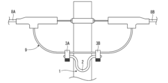
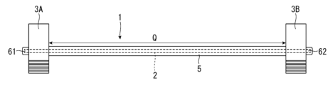
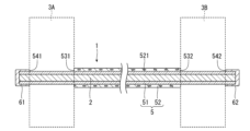
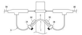
図1に示す電線用工具1は、電線作業の際、例えば、電柱の両側から来る2本の低圧電線8A、8Bの端部間に架設され、これら2本の低圧電線8A、8Bを接続する縁回し線9を切断または接続する際に使用する工具である。このような電線用工具1は、図2に示すように、長尺な芯材2と、芯材2の両端部に配置された第1保持部3Aおよび第2保持部3Bと、芯材2を被覆する保護被覆5およびキャップ61、62と、を有する。以下、これら各部について順に説明する。 The electric wire tool 1 shown in Figure 1 is a tool used during electric wire work, for example, when cutting or connecting an edge wire 9 that is installed between the ends of two low-voltage wires 8A, 8B coming from both sides of a utility pole and connects these two low-voltage wires 8A, 8B. As shown in Figure 2, such an electric wire tool 1 has a long core material 2, a first holding part 3A and a second holding part 3B arranged at both ends of the core material 2, and a protective coating 5 and caps 61, 62 that cover the core material 2. Each of these parts will be explained in order below.

まず、芯材2について説明する。芯材2は、第1保持部3Aと第2保持部3Bとの間の領域Qの少なくとも一部において作業者の腕力によって可撓変形(曲げ変形、捩り変形等)し、かつ、電線作業時に受ける応力に抗して可撓変形後の形状を維持することができる。このような構成によれば、芯材2を可撓変形させるだけで、第1保持部3Aと第2保持部3Bとの相対的位置関係を容易に変化させることができるため、高い作業性を発揮することができる。さらに、操作が簡単なため高い安全性を発揮することができる。 First, the core material 2 will be described. The core material 2 is flexibly deformed (bending, twisting, etc.) by the strength of the worker in at least a part of the region Q between the first holding portion 3A and the second holding portion 3B, and can maintain its shape after flexibly deforming against the stress it receives during wire work. With this configuration, simply by flexibly deforming the core material 2, the relative positional relationship between the first holding portion 3A and the second holding portion 3B can be easily changed, thereby providing high workability. Furthermore, the simple operation provides high safety.

特に、電線用工具1では、芯材2の可撓範囲内において、第1保持部3Aと第2保持部3Bとの相対的位置関係を実質的に無段階で変化させることができる点が従来と比較して顕著な利点となる。ちなみに、前述した特許文献1では、管体が収縮した状態と管体が伸長した状態との2段階でしか第1クリップと第2クリップとの相対的位置関係を変化させることができない。 In particular, the wire tool 1 has a notable advantage over conventional techniques in that the relative positional relationship between the first holding portion 3A and the second holding portion 3B can be changed essentially steplessly within the flexibility range of the core material 2. Incidentally, in the aforementioned Patent Document 1, the relative positional relationship between the first clip and the second clip can only be changed in two stages: when the tube is contracted and when the tube is extended.

本実施形態の芯材2は、金属製であり、長手方向の全域において可撓変形する。そのため、電線用工具1の操作性がより高まる。このように、芯材2を金属製とすることにより、適度な硬さ、具体的には、前述したように、作業者の腕力で芯材2を容易に可撓変形させることができ、かつ、電線作業時に生じる応力に抗して可撓変形後の形状を維持することができる硬さを有し、さらには、高い強度を有する芯材2となる。そのため、高い操作性および安全性を有する電線用工具1となる。 The core material 2 in this embodiment is made of metal and is flexible over the entire length. This improves the operability of the electric wire tool 1. In this way, by making the core material 2 out of metal, the core material 2 has a moderate hardness, specifically, as described above, a hardness that allows the core material 2 to be easily flexible deformed by the strength of the worker and to maintain its shape after flexible deformation against the stress generated during electric wire work, and furthermore, the core material 2 has high strength. This results in an electric wire tool 1 that is highly operable and safe.

なお、芯材2を構成する金属材料としては、特に限定されないが、例えば、アルミニウム(アルミニウム合金を含む)、錫(錫合金を含む)、銅(銅合金を含む)、鉄(鉄合金を含む)、タングステン(タングステン合金を含む)等、比較的柔らかい金属を好適に用いることができる。特に、本実施形態の芯材2は、アルミニウムで構成されている。 The metal material constituting the core material 2 is not particularly limited, but may be a relatively soft metal such as aluminum (including aluminum alloys), tin (including tin alloys), copper (including copper alloys), iron (including iron alloys), or tungsten (including tungsten alloys). In particular, the core material 2 of this embodiment is made of aluminum.

また、芯材2は、図3に示すように、1本の素線で構成されており、その横断面は、円形である。このような構成によれば、芯材2を上下左右どの方向へも同じように可撓変形させることができる。なお、芯材2の直径としては、特に限定されないが、例えば、本実施形態のように構成材料がアルミニウムの場合には、5mm以上、20mm以下程度であることが好ましく、5mm以上、10mm以下であることがより好ましい。このような直径とすることにより、芯材2が適度な硬さとなり、電線用工具1の操作性および安全性が向上する。また、芯材2の長さとしては、特に限定されないが、例えば、300mm以上、700mm以下程度であることが好ましく、400mm以上、600mm以下であることがより好ましい。このような長さとすることにより、芯材2が電線作業に適した長さとなり、電線用工具1の操作性が向上する。 As shown in FIG. 3, the core material 2 is made of a single wire and has a circular cross section. With this configuration, the core material 2 can be flexibly deformed in any direction, including up, down, left, and right. The diameter of the core material 2 is not particularly limited, but for example, when the constituent material is aluminum as in this embodiment, it is preferably 5 mm or more and 20 mm or less, and more preferably 5 mm or more and 10 mm or less. By setting the diameter to such a value, the core material 2 has an appropriate hardness, and the operability and safety of the electric wire tool 1 are improved. The length of the core material 2 is not particularly limited, but for example, it is preferably 300 mm or more and 700 mm or less, and more preferably 400 mm or more and 600 mm or less. By setting the length to such a value, the core material 2 has a length suitable for electric wire work, and the operability of the electric wire tool 1 is improved.

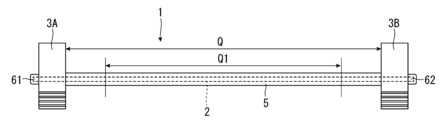
以上、芯材2について説明した。ただし、芯材2の構成は、第1保持部3Aと第2保持部3Bとの間の領域Qの少なくとも一部において可撓変形可能であり、変形後の形状を維持することができれば、限定されない。例えば、芯材2は、樹脂材料等、金属以外の材料で構成されていてもよい。また、芯材2の横断面形状は、円形に限定されず、例えば、四角形、六角形等であってもよい。また、例えば、芯材2は、複数の比較的細い素線を同心円状により合わせた構成であってもよい。また、例えば、図4に示すように、領域Q内の一部の領域Q1が可撓変形し、それ以外の領域では可撓変形しない構成であってもよい。例えば、領域Q1とそれ以外の領域とで構成材料を異ならせることにより、このような構成を実現することができる。また、例えば、図5に示すように、長手方向に沿って複数の自在継手20が連設され、各自在継手20において芯材2を曲げることができる構成であってもよい。 The above describes the core material 2. However, the configuration of the core material 2 is not limited as long as it can be flexibly deformed in at least a part of the region Q between the first holding portion 3A and the second holding portion 3B and can maintain the shape after deformation. For example, the core material 2 may be made of a material other than metal, such as a resin material. The cross-sectional shape of the core material 2 is not limited to a circle, and may be, for example, a square, a hexagon, or the like. For example, the core material 2 may be made of a plurality of relatively thin wires twisted together in a concentric circle. For example, as shown in FIG. 4, a portion of the region Q1 in the region Q may be flexibly deformed, and the other regions may not be flexibly deformed. For example, such a configuration can be realized by making the constituent materials of the region Q1 and the other regions different. For example, as shown in FIG. 5, a plurality of universal joints 20 may be arranged in series along the longitudinal direction, and the core material 2 may be bent at each universal joint 20.

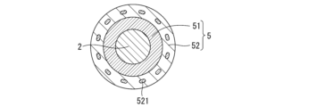
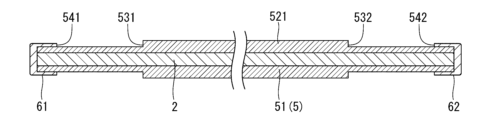
次に、保護被覆5について説明する。保護被覆5は、芯材2を被覆し、絶縁する。このような保護被覆5は、図3に示すように、芯材2を被覆する第1保護被覆51と、第1保護被覆51を被覆する第2保護被覆52と、を有する。第1保護被覆51および第2保護被覆52は、それぞれ、絶縁性を有する。そのため、芯材2を保護被覆5で覆うことにより、電線作業時における芯材2と縁廻し線9との接触が防止され、電線用工具1の安全性が確保される。また、第1保護被覆51および第2保護被覆52は、芯材2の可撓変形を阻害しないよう、十分な柔軟性を有する。 Next, the protective coating 5 will be described. The protective coating 5 covers and insulates the core material 2. As shown in FIG. 3, such a protective coating 5 has a first protective coating 51 that covers the core material 2 and a second protective coating 52 that covers the first protective coating 51. The first protective coating 51 and the second protective coating 52 each have insulating properties. Therefore, by covering the core material 2 with the protective coating 5, contact between the core material 2 and the edge wrapping wire 9 during wire work is prevented, and the safety of the wire tool 1 is ensured. In addition, the first protective coating 51 and the second protective coating 52 have sufficient flexibility so as not to hinder the flexible deformation of the core material 2.

このような第1保護被覆51および第2保護被覆52の構成材料としては、特に限定されず、例えば、PVC(ポリ塩化ビニル)、PE(ポリエチレン)等の樹脂材料や、PTFE(ポリテトラフルオロエチレンシリコーンゴム)等のゴム材料を用いることができる。このような材料を用いることにより、柔軟で、かつ、高い絶縁性を有する第1保護被覆51および第2保護被覆52を安価に形成することができる。 The constituent materials of the first protective coating 51 and the second protective coating 52 are not particularly limited, and may be, for example, a resin material such as PVC (polyvinyl chloride) or PE (polyethylene), or a rubber material such as PTFE (polytetrafluoroethylene silicone rubber). By using such materials, the first protective coating 51 and the second protective coating 52 that are flexible and have high insulating properties can be formed inexpensively.

特に、本実施形態では、第1保護被覆51は、PVC(ポリ塩化ビニル)で形成されたチューブであり、優れた絶縁性を発揮することができる。一方、第2保護被覆52は、シリコーンゴムで形成されたチューブであり、優れた耐候性を発揮することができる。つまり、保護被覆5では、絶縁性および耐候性を共に高いレベルで両立させることができる。このように、第1保護被覆51および第2保護被覆52を別材料で構成し、第1保護被覆51および第2保護被覆52に互いに異なる利点(機能)を付与することにより、より信頼性の高い保護被覆5となる。 In particular, in this embodiment, the first protective coating 51 is a tube made of PVC (polyvinyl chloride) and can exhibit excellent insulation properties. On the other hand, the second protective coating 52 is a tube made of silicone rubber and can exhibit excellent weather resistance. In other words, the protective coating 5 can achieve both high levels of insulation and weather resistance. In this way, by making the first protective coating 51 and the second protective coating 52 out of different materials and imparting different advantages (functions) to the first protective coating 51 and the second protective coating 52, a more reliable protective coating 5 can be obtained.

また、図3に示すように、第2保護被覆52には、繊維を編んで形成されたメッシュ521が埋設されている。このように、第2保護被覆52をメッシュ入りのチューブとすることにより、保護被覆5の強度を高めることができる。 As shown in FIG. 3, a mesh 521 formed by weaving fibers is embedded in the second protective coating 52. In this way, by making the second protective coating 52 a tube containing a mesh, the strength of the protective coating 5 can be increased.

また、図6に示すように、第1保護被覆51は、芯材2とほぼ同じ長さであり、芯材2の長手方向の全域を覆っている。これに対して、第2保護被覆52は、芯材2よりも短く、芯材2の両端部を除く中央部を覆っている。したがって、保護被覆5の両端部では、第1保護被覆51が第2保護被覆52から露出しており、第1保護被覆51の表面と第2保護被覆52の端面とで形成された段差531、532が形成されている。後述するように、電線用工具1では、これら段差531、532に第1保持部3Aおよび第2保持部3Bを突き当てることにより、第1保持部3Aおよび第2保持部3Bの位置を定めている。つまり、保護被覆5は、芯材2を絶縁被覆するだけでなく、第1保持部3Aおよび第2保持部3Bの位置を定める位置決め部としても機能する。そのため、別途、位置決め部を設ける場合と比べて電線用工具1の構成がシンプルとなり、電線用工具1の軽量化や、製造コストの削減を図ることができる。 6, the first protective coating 51 is approximately the same length as the core material 2 and covers the entire area of the core material 2 in the longitudinal direction. In contrast, the second protective coating 52 is shorter than the core material 2 and covers the center of the core material 2 except for both ends. Therefore, at both ends of the protective coating 5, the first protective coating 51 is exposed from the second protective coating 52, and steps 531, 532 are formed between the surface of the first protective coating 51 and the end face of the second protective coating 52. As will be described later, in the electric wire tool 1, the first holding portion 3A and the second holding portion 3B are abutted against these steps 531, 532 to determine the positions of the first holding portion 3A and the second holding portion 3B. In other words, the protective coating 5 not only insulates the core material 2, but also functions as a positioning portion that determines the positions of the first holding portion 3A and the second holding portion 3B. This simplifies the configuration of the wire tool 1 compared to when a separate positioning unit is provided, making it possible to reduce the weight of the wire tool 1 and reduce manufacturing costs.

また、第2保護被覆52は、光透過性を有しており、第2保護被覆52を介して、その下層側に位置する第1保護被覆51を視認可能である。特に、本実施形態では、実質的に無色透明である。これにより、第1保護被覆51の破損、損傷等をいち早く発見することができる。そのため、電線用工具1の安全性がより高まる。 The second protective coating 52 is also optically transparent, and the first protective coating 51 located underneath can be seen through the second protective coating 52. In particular, in this embodiment, the second protective coating 52 is substantially colorless and transparent. This allows for early detection of any breakage or damage to the first protective coating 51. This further enhances the safety of the wire tool 1.

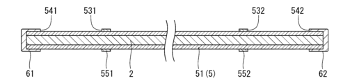
以上、保護被覆5について説明した。ただし、保護被覆5の構成は、特に限定されない。例えば、保護被覆5から第2保護被覆52を省略してもよい。この場合、例えば、図7に示すように、第1保護被覆52の両端部の肉厚を中央部の肉厚よりも薄くすることにより、段差531、532を形成してもよいし、図8に示すように、第1保護被覆52の外周面にリング状のストッパー551、552を固定することにより、段差531、532を形成してもよい。また、例えば、第2保護被覆52をさらに第3、第4…の保護被覆で覆ってもよい。また、例えば、芯材2が絶縁性の材料で構成されている場合には、保護被覆5を省略してもよい。 The protective coating 5 has been described above. However, the configuration of the protective coating 5 is not particularly limited. For example, the second protective coating 52 may be omitted from the protective coating 5. In this case, for example, as shown in FIG. 7, the thickness of both ends of the first protective coating 52 may be made thinner than the thickness of the center, thereby forming steps 531, 532, or as shown in FIG. 8, the steps 531, 532 may be formed by fixing ring-shaped stoppers 551, 552 to the outer circumferential surface of the first protective coating 52. In addition, for example, the second protective coating 52 may be further covered with a third, fourth, ... protective coating. In addition, for example, when the core material 2 is made of an insulating material, the protective coating 5 may be omitted.

次に、キャップ61、62について説明する。これらキャップ61、62は、共に絶縁性を有する。図6に示すように、キャップ61は、第1保護被覆51(芯材2)の一方の端部に被せられ、芯材2の一方の端面を被覆している。一方、キャップ62は、第1保護被覆51(芯材2)の他方の端部に被せられ、芯材2の他方の端面を被覆している。このように、芯材2の両端面を絶縁性のキャップ61、62で覆うことにより、電線作業時における芯材2と縁廻し線9との接触が防止され、電線用工具1の安全性が確保される。なお、キャップ61、62の抜けを防止するために、接着剤等を用いてキャップ61、62と第1保護被覆51とを強固に固定することが好ましい。これにより、電線用工具1の安全性が向上する。 Next, the caps 61 and 62 will be described. Both of these caps 61 and 62 are insulating. As shown in FIG. 6, the cap 61 is placed on one end of the first protective coating 51 (core material 2) and covers one end face of the core material 2. On the other hand, the cap 62 is placed on the other end of the first protective coating 51 (core material 2) and covers the other end face of the core material 2. In this way, by covering both end faces of the core material 2 with the insulating caps 61 and 62, contact between the core material 2 and the edge wrapping wire 9 during wire work is prevented, and the safety of the wire tool 1 is ensured. In addition, in order to prevent the caps 61 and 62 from coming off, it is preferable to firmly fix the caps 61 and 62 to the first protective coating 51 using an adhesive or the like. This improves the safety of the wire tool 1.

このようなキャップ61、62の構成材料としては、特に限定されず、例えば、PVC(ポリ塩化ビニル)、PE(ポリエチレン)、PC(ポリカーボネート)等の樹脂材料や、PTFE(ポリテトラフルオロエチレンシリコーンゴム)等のゴム材料を用いることができる。このような材料を用いることにより、高い絶縁性を有するキャップ61、62を安価に形成することができる。 The constituent material of the caps 61, 62 is not particularly limited, and may be, for example, a resin material such as PVC (polyvinyl chloride), PE (polyethylene), or PC (polycarbonate), or a rubber material such as PTFE (polytetrafluoroethylene silicone rubber). By using such materials, the caps 61, 62 having high insulating properties can be formed inexpensively.

また、キャップ61、62は、第1保護被覆51と異なる色を有する。例えば、キャップ61、62が黒色であり、第1保護被覆51が赤色、青色、黄色等である。このような構成によれば、キャップ61、62を容易に確認することができ、キャップ61、62の離脱をいち早く発見することができる。そのため、電線用工具1の安全性がより高まる。 The caps 61, 62 have a different color from the first protective coating 51. For example, the caps 61, 62 are black, and the first protective coating 51 is red, blue, yellow, or the like. With this configuration, the caps 61, 62 can be easily identified, and any detachment of the caps 61, 62 can be quickly detected. This further increases the safety of the wire tool 1.

また、図6に示すように、保護被覆5の一方の端部には第1保護被覆51の表面とキャップ61の端面とで形成された段差541が形成され、保護被覆5の他方の端部には第1保護被覆51の表面とキャップ62の端面とで形成された段差542が形成されている。後述するように、これら段差541、542に第1保持部3Aおよび第2保持部3Bが突き当たることにより、芯材2からの第1保持部3Aおよび第2保持部3Bの離脱が防止される。つまり、キャップ61、62は、芯材2を絶縁被覆するだけでなく、第1保持部3Aおよび第2保持部3Bの離脱を防止する離脱防止部としても機能する。そのため、別途、離脱防止部を設ける場合と比べて電線用工具1の構成がシンプルとなり、電線用工具1の軽量化や、製造コストの削減を図ることができる。 As shown in FIG. 6, a step 541 is formed at one end of the protective coating 5 by the surface of the first protective coating 51 and the end face of the cap 61, and a step 542 is formed at the other end of the protective coating 5 by the surface of the first protective coating 51 and the end face of the cap 62. As described later, the first holding portion 3A and the second holding portion 3B abut against these steps 541, 542, preventing the first holding portion 3A and the second holding portion 3B from being separated from the core material 2. In other words, the caps 61, 62 not only insulate the core material 2, but also function as a separation prevention portion that prevents the first holding portion 3A and the second holding portion 3B from being separated. Therefore, the configuration of the electric wire tool 1 is simpler than when a separate separation prevention portion is provided, and the weight of the electric wire tool 1 and the manufacturing cost can be reduced.

以上、キャップ61、62について説明した。ただし、キャップ61、62の構成は、特に限定されない。例えば、キャップ61、62は、第1保護被覆51と同じ色であってもよい。また、例えば、第1保護被覆51等によって芯材2の両端面が既に被覆されている場合には、キャップ61、62を省略してもよい。 The caps 61 and 62 have been described above. However, the configuration of the caps 61 and 62 is not particularly limited. For example, the caps 61 and 62 may be the same color as the first protective coating 51. Also, for example, if both end faces of the core material 2 are already covered with the first protective coating 51 or the like, the caps 61 and 62 may be omitted.

次に、第1保持部3Aおよび第2保持部3Bについて説明する。図2に示すように、第1保持部3Aは、芯材2の一方の端部(一端部)に配置され、第2保持部3Bは、芯材2の他方の端部(他端部)に配置されている。このように、芯材2の両端部に第1保持部3Aおよび第2保持部3Bを配置することにより、芯材2の全長を短く抑えつつ、第1保持部3Aおよび第2保持部3Bの離間距離を大きく確保することができる。また、第1保持部3Aや第2保持部3Bよりも外側への芯材2の突出が抑えられる。そのため、小型で高い操作性を有する電線用工具1となる。 Next, the first holding portion 3A and the second holding portion 3B will be described. As shown in FIG. 2, the first holding portion 3A is disposed at one end (one end) of the core material 2, and the second holding portion 3B is disposed at the other end (the other end) of the core material 2. By disposing the first holding portion 3A and the second holding portion 3B at both ends of the core material 2 in this way, it is possible to ensure a large separation distance between the first holding portion 3A and the second holding portion 3B while keeping the overall length of the core material 2 short. In addition, the core material 2 is prevented from protruding outward beyond the first holding portion 3A and the second holding portion 3B. This results in a small-sized electric wire tool 1 with high operability.

なお、第1保持部3Aおよび第2保持部3Bは、互いに同じ構成であるため、以下では、これらをまとめて「保持部3」として説明する。 Note that the first holding unit 3A and the second holding unit 3B have the same configuration, so in the following they will be collectively referred to as "holding unit 3."

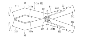
保持部3は、縁廻し線9を保持(挟持)するクリップである。このように、保持部3をクリップで構成することにより、縁廻し線9を容易かつ確実に保持することができる。なお、保持部3は、外径の異なる縁廻し線9を保持するができる。具体的には、一般的な縁廻し線9の外径が7mm以上、23mm以下であるため、保持部3は、この範囲の外径を有する縁廻し線9を好適に保持できるように構成されている。このような保持部3は、図9および図10に示すように、回動軸Jまわりに反対方向に回動することにより開閉して縁廻し線9を保持(挟持)する一対の保持アーム31、32と、保持アーム31、32を閉じる方向に付勢するトーションばね33と、を有する。 The holding part 3 is a clip that holds (clamps) the edge wrapping wire 9. In this way, by configuring the holding part 3 as a clip, the edge wrapping wire 9 can be easily and securely held. The holding part 3 can hold edge wrapping wires 9 with different outer diameters. Specifically, since the outer diameter of a typical edge wrapping wire 9 is 7 mm or more and 23 mm or less, the holding part 3 is configured to suitably hold edge wrapping wires 9 with outer diameters in this range. As shown in Figures 9 and 10, such a holding part 3 has a pair of holding arms 31, 32 that open and close by rotating in opposite directions around the rotation axis J to hold (clamp) the edge wrapping wire 9, and a torsion spring 33 that biases the holding arms 31, 32 in a closing direction.

保持アーム31は、樹脂材料等の絶縁性の材料で構成されている。また、保持アーム31は、回動軸Jよりも先端側に位置する作用部311と、回動軸Jよりも基端側に位置する操作部312と、作用部311と操作部312との間に位置し、回動軸Jに沿う方向に離間して配置された一対の接続部313、314と、を有する。また、作用部311の縁廻し線9と接触する面(後述する作用部321と対向する面)には、ゴム材料で構成された滑り止め311aが設けられている。また、一対の接続部313、314には、芯材2を挿通するための挿通孔313a、314aが形成されており、これら2つの挿通孔313a、314aは、回動軸Jに沿って配置されている。 The holding arm 31 is made of an insulating material such as a resin material. The holding arm 31 has an action part 311 located on the tip side of the rotation axis J, an operation part 312 located on the base side of the rotation axis J, and a pair of connection parts 313, 314 located between the action part 311 and the operation part 312 and arranged at a distance in the direction along the rotation axis J. A non-slip surface 311a made of a rubber material is provided on the surface of the action part 311 that contacts the edge wrapping line 9 (the surface facing the action part 321 described later). The pair of connection parts 313, 314 have insertion holes 313a, 314a for inserting the core material 2, and these two insertion holes 313a, 314a are arranged along the rotation axis J.

保持アーム32は、前述した保持アーム31と同様の構成である。つまり、保持アーム32は、樹脂材料等の絶縁性の材料で構成されている。また、保持アーム32は、回動軸Jよりも先端側に位置する作用部321と、回動軸Jよりも基端側に位置する操作部322と、作用部321と操作部322との間に位置し、回動軸Jに沿う方向に離間して配置された一対の接続部323、324と、を有する。また、作用部321の縁廻し線9と接触する面(作用部311と対向する面)には、ゴム材料で構成された滑り止め321aが設けられている。また、一対の接続部323、324には、芯材2を挿通するための挿通孔323a、324aが形成され、これら2つの挿通孔323a、324aは、回動軸Jに沿って配置されている。また、接続部323は、接続部313に内接し、接続部324は、接続部314に外接している。つまり、接続部323の外側の主面が接続部313の内側の主面に接し、接続部324の内側の主面が接続部314の外側の主面に接している。 The holding arm 32 has the same configuration as the holding arm 31 described above. That is, the holding arm 32 is made of an insulating material such as a resin material. The holding arm 32 also has an action part 321 located on the tip side of the rotation axis J, an operation part 322 located on the base end side of the rotation axis J, and a pair of connection parts 323, 324 located between the action part 321 and the operation part 322 and arranged at a distance in the direction along the rotation axis J. In addition, a non-slip surface 321a made of a rubber material is provided on the surface of the action part 321 that contacts the edge wrapping line 9 (the surface facing the action part 311). In addition, the pair of connection parts 323, 324 are formed with insertion holes 323a, 324a for inserting the core material 2, and these two insertion holes 323a, 324a are arranged along the rotation axis J. Additionally, connection portion 323 is inscribed in connection portion 313, and connection portion 324 is circumscribed in connection portion 314. In other words, the outer main surface of connection portion 323 is in contact with the inner main surface of connection portion 313, and the inner main surface of connection portion 324 is in contact with the outer main surface of connection portion 314.

そして、芯材2が第1保護被覆51毎、挿通孔313a、314a、323a、324aに挿通されている。具体的には、キャップ61、62が装着される前の芯材2を挿通孔313a、323a、314a、324aの順でこれらに挿通し、端部を挿通孔324aから突出させる。そして、突出した端部にキャップ61、62を装着する。そのため、電線用工具1では、回動軸Jと芯材2の中心軸とが一致する。 The core material 2 is then inserted into the insertion holes 313a, 314a, 323a, and 324a for each first protective coating 51. Specifically, before the caps 61 and 62 are attached, the core material 2 is inserted into the insertion holes 313a, 323a, 314a, and 324a in this order, and the end portion protrudes from the insertion hole 324a. The caps 61 and 62 are then attached to the protruding end portion. Therefore, in the wire tool 1, the rotation axis J and the central axis of the core material 2 coincide with each other.

なお、挿通孔313a、314a、323a、324aの内径は、第1保護被覆51の外径と等しいか、若干大きい。そして、トーションばね33の反力により、挿通孔313a、314a、323a、324aにせん断方向に開く力により抵抗が生じる。そのため、第1保護被覆51と各保持アーム31、32との間に適度な摺動抵抗が生じ、作業者の腕力によって保持部3を芯材2に対して回動軸Jまわりに回転させることができ、かつ、電線作業時に受ける応力に抗して回転後の保持部3の向きを維持することができる構成となる。このような構成によれば、芯材2の可撓変形(曲げ変形、捩り変形等)に加えて、保持部3の回動軸Jまわりの回転によっても第1、第2保持部3A、3Bの相対的な位置関係を変化させることができる。そのため、電線用工具1の操作性がより高まる。 The inner diameters of the insertion holes 313a, 314a, 323a, and 324a are equal to or slightly larger than the outer diameter of the first protective coating 51. The reaction force of the torsion spring 33 creates resistance in the insertion holes 313a, 314a, 323a, and 324a by opening them in the shear direction. Therefore, a moderate sliding resistance is generated between the first protective coating 51 and each holding arm 31, 32, and the holding part 3 can be rotated around the rotation axis J relative to the core material 2 by the arm strength of the worker, and the orientation of the holding part 3 after rotation can be maintained against the stress received during wire work. With this configuration, in addition to the flexible deformation (bending deformation, torsional deformation, etc.) of the core material 2, the relative positional relationship between the first and second holding parts 3A and 3B can also be changed by the rotation of the holding part 3 around the rotation axis J. Therefore, the operability of the wire tool 1 is further improved.

トーションばね33は、接続部323、324の間に位置し、回動軸Jに沿う方向に離間して2つ設けられている。各トーションばね33は、コイル331と、コイル331の一端から延出するアーム332と、コイル331の他端から延出するアーム333と、を有する。そして、芯材2が第1保護被覆51毎、各トーションばね33のコイル331に挿入されている。なお、各コイル331の内径は、第1保護被覆51の外径よりも若干大きい。また、各トーションばね33は、圧縮させた状態(コイル331を巻き込んだ状態)で保持アーム31、32の間に配置され、一方のアーム332が保持アーム31の操作部312に当接し、他方のアーム333が保持アーム32の操作部322に当接している。そのため、各トーションばね33の弾性(復元力)によって、保持アーム31、32が閉じる方向に常に付勢される。 The torsion spring 33 is located between the connection parts 323 and 324, and two are provided spaced apart in the direction along the rotation axis J. Each torsion spring 33 has a coil 331, an arm 332 extending from one end of the coil 331, and an arm 333 extending from the other end of the coil 331. The core material 2 is inserted into the coil 331 of each torsion spring 33 for each first protective coating 51. The inner diameter of each coil 331 is slightly larger than the outer diameter of the first protective coating 51. Each torsion spring 33 is disposed between the holding arms 31 and 32 in a compressed state (with the coil 331 wound), with one arm 332 abutting against the operating part 312 of the holding arm 31 and the other arm 333 abutting against the operating part 322 of the holding arm 32. Therefore, the elasticity (restoring force) of each torsion spring 33 constantly biases the holding arms 31 and 32 in the closing direction.

このような構成の保持部3では、操作部312、322を摘まみ、トーションばね33の弾性に抗して作用部311、321を開き、作用部311、321の間に縁廻し線9を挿入し、その後、作用部311、321を閉じて縁廻し線9を挟持することにより、縁廻し線9を保持することができる。特に、本実施形態では、回動軸Jが芯材2の中心軸と一致しているため、保持アーム31、32が芯材2の中心軸まわりに回動して保持部3が開閉する。そのため、保持部3の操作性が高まる。 In the holding unit 3 configured in this way, the edge wrapping wire 9 can be held by pinching the operating parts 312, 322, opening the action parts 311, 321 against the elasticity of the torsion spring 33, inserting the edge wrapping wire 9 between the action parts 311, 321, and then closing the action parts 311, 321 to clamp the edge wrapping wire 9. In particular, in this embodiment, since the rotation axis J coincides with the central axis of the core material 2, the holding arms 31, 32 rotate around the central axis of the core material 2 to open and close the holding unit 3. This improves the operability of the holding unit 3.

ここで、電線用工具1では、第1保持部3Aの接続部313の外側の主面が段差531と当接し、接続部314の外側の主面が段差541と当接している。つまり、第1保持部3Aは、段差531、541の間に挟まれるように設けられている。このような構成によれば、第1保持部3Aは、芯材2に対して芯材2の長手方向にスライドすることができず、芯材2の長手方向における位置が固定される。同様に、第2保持部3Bの接続部313の外側の主面が段差532と当接し、接続部314の外側の主面が段差542と当接している。つまり、第2保持部3Bは、段差532、542の間に挟まれるように設けられている。このような構成によれば、第2保持部3Bは、芯材2に対して芯材2の長手方向にスライドすることができず、芯材2の長手方向における位置が固定される。このように、第1、第2保持部3A、3Bの芯材2の長手方向における位置を固定することにより、第1、第2保持部3A、3Bの余計な動きを規制することができ、電線用工具1の操作性がより高まる。 Here, in the electric wire tool 1, the outer main surface of the connection portion 313 of the first holding portion 3A abuts against the step 531, and the outer main surface of the connection portion 314 abuts against the step 541. That is, the first holding portion 3A is provided so as to be sandwiched between the steps 531 and 541. According to this configuration, the first holding portion 3A cannot slide in the longitudinal direction of the core material 2 relative to the core material 2, and the position in the longitudinal direction of the core material 2 is fixed. Similarly, the outer main surface of the connection portion 313 of the second holding portion 3B abuts against the step 532, and the outer main surface of the connection portion 314 abuts against the step 542. That is, the second holding portion 3B is provided so as to be sandwiched between the steps 532 and 542. According to this configuration, the second holding portion 3B cannot slide in the longitudinal direction of the core material 2 relative to the core material 2, and the position in the longitudinal direction of the core material 2 is fixed. In this way, by fixing the positions of the first and second holding parts 3A and 3B in the longitudinal direction of the core material 2, unnecessary movement of the first and second holding parts 3A and 3B can be restricted, and the operability of the electric wire tool 1 is further improved.

なお、芯材2がまっすぐに伸びた状態における第1保持部3Aと第2保持部3Bとの離間距離、言い換えると芯材2の領域Qの長さとしては、特に限定されないが、例えば、300mm以上、600mm以下程度であることが好ましく、400mm以上、500mm以下であることがより好ましい。このような長さとすることにより、第1保持部3Aと第2保持部3Bとの離間距離が電線作業に適した長さとなり、電線用工具1の操作性が向上する。 The distance between the first and second holding parts 3A and 3B when the core material 2 is stretched straight, in other words the length of the region Q of the core material 2, is not particularly limited, but is preferably, for example, 300 mm or more and 600 mm or less, and more preferably 400 mm or more and 500 mm or less. By setting it to such a length, the distance between the first and second holding parts 3A and 3B becomes a length suitable for wire work, improving the operability of the wire tool 1.

以上、第1保持部3Aおよび第2保持部3Bについて説明した。ただし、第1保持部3Aおよび第2保持部3Bの構成は、特に限定されない。例えば、第1保持部3Aおよび第2保持部3Bは、芯材2の中心軸まわりに回転することができなくてもよい。また、第1保持部3Aおよび第2保持部3Bは、芯材2に対して芯材2の長手方向に移動可能であってもよい。また、トーションばね33の数は、1つであってもよいし、3つ以上であってもよい。 The above describes the first retaining portion 3A and the second retaining portion 3B. However, the configuration of the first retaining portion 3A and the second retaining portion 3B is not particularly limited. For example, the first retaining portion 3A and the second retaining portion 3B may not be able to rotate around the central axis of the core material 2. Furthermore, the first retaining portion 3A and the second retaining portion 3B may be able to move in the longitudinal direction of the core material 2 relative to the core material 2. Furthermore, the number of torsion springs 33 may be one, or three or more.

また、例えば、挿通孔313a、314a、323a、324aの内径が第1保護被覆51の外径と等しいか、第1保護被覆51の外径よりも若干大きく、各コイル331の内径が第1保護被覆51の外径よりも小さくなっていてもよい。つまり、芯材2が挿通孔313a、314a、323a、324aではなく、各コイル331に圧入されていてもよい。このような構成とすることにより、第1保護被覆51と各コイル331との間に適度な摺動抵抗が生じ、本実施形態と同様に、作業者の腕力によって保持部3を芯材2に対して回動軸Jまわりに回転させることができ、かつ、電線作業時に受ける応力に抗して回転後の保持部3の向きを維持することができる構成となる。さらには、保持アーム31、32と第1保護被覆51との間の摺動抵抗を小さくおさえることができるため、保持アーム31、32の開閉を行い易くなる。 For example, the inner diameter of the insertion holes 313a, 314a, 323a, and 324a may be equal to or slightly larger than the outer diameter of the first protective coating 51, and the inner diameter of each coil 331 may be smaller than the outer diameter of the first protective coating 51. In other words, the core material 2 may be pressed into each coil 331, not into the insertion holes 313a, 314a, 323a, and 324a. With this configuration, an appropriate sliding resistance is generated between the first protective coating 51 and each coil 331, and as in this embodiment, the holding part 3 can be rotated around the rotation axis J relative to the core material 2 by the worker's strength, and the orientation of the holding part 3 after rotation can be maintained against the stress received during wire work. Furthermore, since the sliding resistance between the holding arms 31 and 32 and the first protective coating 51 can be kept small, it becomes easier to open and close the holding arms 31 and 32.

以上、電線用工具1の構成について説明した。次に、電線用工具1を用いた電線作業方法について説明する。電線作業方法は、図11に示すように、縁廻し線9に電線用工具1を装着する装着工程S1と、縁廻し線9を切断する切断工程S2と、縁廻し線9の切断端末91、92を所定の向きとする向き変更工程S3と、縁廻し線9の切断端末91、92同士を接続する接続工程S4と、縁廻し線9から電線用工具1を取り外す取外工程S5と、を有する。 The configuration of the electric wire tool 1 has been described above. Next, an electric wire work method using the electric wire tool 1 will be described. As shown in FIG. 11, the electric wire work method includes an attachment process S1 for attaching the electric wire tool 1 to the edge wrapping wire 9, a cutting process S2 for cutting the edge wrapping wire 9, an orientation change process S3 for orienting the cutting ends 91, 92 of the edge wrapping wire 9 in a predetermined orientation, a connection process S4 for connecting the cutting ends 91, 92 of the edge wrapping wire 9 to each other, and a removal process S5 for removing the electric wire tool 1 from the edge wrapping wire 9.

装着工程S1では、図12に示すように、予め芯材2をU字状に曲げておき、縁廻し線9の延在方向の間隔をあけた箇所を第1保持部3Aおよび第2保持部3Bでそれぞれ保持する。次に、切断工程S2では、図13に示すように、縁廻し線9を第1保持部3Aおよび第2保持部3Bの間の箇所で切断する。次に、図14に示すように、向き変更工程S3では、芯材2を可撓変形させたり、第1保持部3Aおよび第2保持部3Bの少なくとも一方を芯材2に対して回転させたりして、縁廻し線9の切断端末91、92同士を離隔すると共に、各端末を所定の向きに向ける。次に、図15に示すように、各切断端末91、92に絶縁性の端末カバー90を装着する。 In the installation step S1, as shown in FIG. 12, the core material 2 is bent into a U-shape in advance, and the first and second holding parts 3A and 3B hold the edge-wrapped wire 9 at intervals in the extension direction. Next, in the cutting step S2, as shown in FIG. 13, the edge-wrapped wire 9 is cut at a location between the first and second holding parts 3A and 3B. Next, as shown in FIG. 14, in the orientation change step S3, the core material 2 is flexibly deformed, or at least one of the first and second holding parts 3A and 3B is rotated relative to the core material 2, to separate the cut ends 91 and 92 of the edge-wrapped wire 9 from each other and to orient each end in a predetermined direction. Next, as shown in FIG. 15, an insulating terminal cover 90 is attached to each cut end 91 and 92.

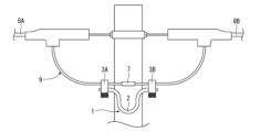
そして、この状態で所定の必要な作業が行われ、作業が終了した後に接続工程S4を行う。図16に示すように、接続工程S4では、芯材2を可撓変形させたり、第1保持部3Aおよび第2保持部3Bの少なくとも一方を芯材2に対して回転させたりして、縁廻し線9の各切断端末91、92を切断時の位置に戻し、各切断端末91、92から端末カバー90を取り外す。そして、各切断端末91、92の皮剥ぎをし、図17に示すように、皮剥ぎをした切断端末91、92同士をスリーブ7で接続する。次に、取り外す取外工程S5では、図18に示すように、縁廻し線9から電線用工具1を取り外す。以上により、電線作業が終了する。 Then, in this state, the required work is performed, and after the work is completed, the connection step S4 is performed. As shown in FIG. 16, in the connection step S4, the core material 2 is flexibly deformed, and at least one of the first holding part 3A and the second holding part 3B is rotated relative to the core material 2, so that the cut ends 91, 92 of the edge wrapping wire 9 are returned to the positions at the time of cutting, and the end covers 90 are removed from the cut ends 91, 92. Then, the cut ends 91, 92 are stripped, and the stripped cut ends 91, 92 are connected to each other with a sleeve 7, as shown in FIG. 17. Next, in the removal step S5, the wire tool 1 is removed from the edge wrapping wire 9, as shown in FIG. 18. With the above, the wire work is completed.

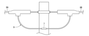
このような電線作業方法によれば、操作性および安全性に優れた電線用工具1を用いるため、高い安全性を発揮することができる。なお、電線用工具1を収納する際は、例えば、図19に示すように、芯材2を円状に湾曲させることによりコンパクトな収納が可能となる。 This method of working with electric wires uses the electric wire tool 1, which is easy to operate and safe, and therefore provides a high level of safety. When storing the electric wire tool 1, for example, as shown in FIG. 19, the core material 2 can be curved into a circular shape to allow compact storage.

以上、本発明の電線用工具および電線作業方法を図示の実施形態に基づいて説明したが、本発明は、これに限定されるものではなく、各部の構成は、同様の機能を有する任意の構成または工程に置換することができる。また、本発明に、他の任意の構成または工程が付加されていてもよい。 The wire tool and wire working method of the present invention have been described above based on the illustrated embodiment, but the present invention is not limited to this, and the configuration of each part can be replaced with any configuration or process having a similar function. In addition, any other configuration or process may be added to the present invention.

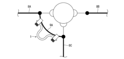
電線用工具1の使用方法としては、上述した実施形態に限定されず、どのような電線作業にも好適に用いることができる。例えば、図20に示すように、電線用工具1は、低圧電線8Aと電柱から分岐する低圧電線8Cとの端部間に架設され、これら2本の低圧電線8A、8Cを接続する縁回し線9Aに装着してもよい。また、図21に示すように、電線用工具1は、低圧電線8Aと建物への引込線8Dとの端部間に架設され、低圧電線8Aと引込線8Dを接続する縁回し線9Bに装着してもよい。また、図22に示すように、電線用工具1は、変圧器100と低圧電線8Aを繋ぐ立ち上がり線8Eに装着してもよい。また、図23に示すように、電線用工具1は、立ち上がり線8Eと引込線8Dとの間に架設され、立ち上がり線8Eと引込線8Dを接続する縁回し線9Cに装着してもよい。 The method of using the electric wire tool 1 is not limited to the above-mentioned embodiment, and it can be suitably used for any electric wire work. For example, as shown in FIG. 20, the electric wire tool 1 may be installed between the ends of a low-voltage wire 8A and a low-voltage wire 8C branching off from a utility pole, and may be attached to an edge wire 9A connecting these two low-voltage wires 8A and 8C. Also, as shown in FIG. 21, the electric wire tool 1 may be installed between the ends of a low-voltage wire 8A and a service line 8D to a building, and may be attached to an edge wire 9B connecting the low-voltage wire 8A and the service line 8D. Also, as shown in FIG. 22, the electric wire tool 1 may be installed on a riser wire 8E connecting a transformer 100 and a low-voltage wire 8A. Also, as shown in FIG. 23, the electric wire tool 1 may be installed between the riser wire 8E and the service line 8D, and may be attached to an edge wire 9C connecting the riser wire 8E and the service line 8D.

1…電線用工具、100…変圧器、2…芯材、20…自在継手、3…保持部、3A…第1保持部、3B…第2保持部、31…保持アーム、311…作用部、311a…滑り止め、311b…爪部、312…操作部、313…接続部、313a…挿通孔、314…接続部、314a…挿通孔、32…保持アーム、321…作用部、321a…滑り止め、321b…爪部、322…操作部、323…接続部、323a…挿通孔、324…接続部、324a…挿通孔、33…トーションばね、331…コイル、332…アーム、333…アーム、5…保護被覆、51…第1保護被覆、52…第2保護被覆、521…メッシュ、531…段差、532…段差、541…段差、542…段差、551…ストッパー、552…ストッパー、61…キャップ、62…キャップ、7…スリーブ、8A…低圧電線、8B…低圧電線、8C…低圧電線、8D…引込線、8E…立ち上がり線、9…縁廻し線、9A…縁廻し線、9B…縁廻し線、90…端末カバー、91…切断端末、92…切断端末、J…回動軸、Q…領域、Q1…領域、S1…装着工程、S2…切断工程、S3…向き変更工程、S4…接続工程、S5…取外工程 1...tool for electric wire, 100...transformer, 2...core material, 20...universal joint, 3...holding part, 3A...first holding part, 3B...second holding part, 31...holding arm, 311...action part, 311a...anti-slip, 311b...claw part, 312...operation part, 313...connection part, 313a...insertion hole, 314...connection part, 314a...insertion hole, 32...holding arm, 321...action part, 321a...anti-slip, 321b...claw part, 322...operation part, 323...connection part, 323a...insertion hole, 324...connection part, 324a...insertion hole, 33...torsion spring, 331...coil, 332...arm, 333...arm, 5...protective coating , 51...first protective covering, 52...second protective covering, 521...mesh, 531...step, 532...step, 541...step, 542...step, 551...stopper, 552...stopper, 61...cap, 62...cap, 7...sleeve, 8A...low-voltage wire, 8B...low-voltage wire, 8C...low-voltage wire, 8D...inlet wire, 8E...rise wire, 9...edge wire, 9A...edge wire, 9B...edge wire, 90...terminal cover, 91...disconnection terminal, 92...disconnection terminal, J...rotation axis, Q...area, Q1...area, S1...mounting process, S2...disconnection process, S3...orientation change process, S4...connection process, S5...removal process

Claims (12)

電線を切断または接続する際に使用する電線用工具であって、
長尺な芯材と、
前記芯材に配置され、前記電線を保持する第1保持部と、
前記芯材に前記第1保持部と離間して配置され、前記電線を保持する第2保持部と、を有し、
前記芯材は、前記第1保持部と前記第2保持部との間の少なくとも一部の領域において可撓変形し、かつ、前記可撓変形後の形状を維持することができることを特徴とする電線用工具。
A tool for electric wires used for cutting or connecting electric wires,
A long core material,
A first holding portion that is disposed on the core material and holds the electric wire;
a second holding portion disposed on the core material and spaced apart from the first holding portion and holding the electric wire;
The core material is capable of flexibly deforming in at least a portion of the region between the first holding portion and the second holding portion, and of maintaining the shape after the flexibly deforming.
前記第1保持部および前記第2保持部は、それぞれ、前記芯材に対して前記芯材の中心軸まわりに回転可能である請求項1に記載の電線用工具。 The wire tool according to claim 1, wherein the first holding part and the second holding part are each rotatable around the central axis of the core material relative to the core material. 前記第1保持部および前記第2保持部は、前記芯材に対して前記芯材の長手方向における位置が固定されている請求項1に記載の電線用工具。 The wire tool according to claim 1, wherein the first holding part and the second holding part are fixed in position relative to the core material in the longitudinal direction of the core material. 前記芯材は、金属製である請求項1に記載の電線用工具。 The wire tool according to claim 1, wherein the core material is made of metal. 前記芯材を被覆する絶縁性の保護被覆を有する請求項4に記載の電線用工具。 The wire tool according to claim 4, which has an insulating protective coating covering the core material. 前記第1保持部および前記第2保持部は、それぞれ、前記電線を把持するクリップである請求項1に記載の電線用工具。 The electric wire tool according to claim 1, wherein the first holding part and the second holding part are clips that grip the electric wire. 前記クリップは、前記芯材の中心軸まわりに開閉する一対の保持アームを有する請求項6に記載の電線用工具。 The wire tool according to claim 6, wherein the clip has a pair of holding arms that open and close around the central axis of the core material. 前記第1保持部と前記第2保持部との離間距離は、30cm以上60cm以下である請求項1に記載の電線用工具。 The wire tool according to claim 1, wherein the distance between the first holding part and the second holding part is 30 cm or more and 60 cm or less. 前記第1保持部は、前記芯材の一端部に配置され、
前記第2保持部は、前記芯材の他端部に配置されている請求項1に記載の電線用工具。
The first retaining portion is disposed at one end of the core material,
The wire tool according to claim 1 , wherein the second holding portion is disposed at the other end of the core.
長尺な芯材と、
前記芯材に配置され、電線を保持する第1保持部と、
前記芯材に前記第1保持部と離間して配置され、前記電線を保持する第2保持部と、を有し、
前記芯材は、前記第1保持部と前記第2保持部との間の少なくとも一部の領域において可撓変形し、かつ、前記可撓変形後の形状を維持することができる電線用工具を用い、
前記電線の延在方向の間隔をあけた箇所を前記第1保持部および前記第2保持部でそれぞれ保持する装着工程と、
前記電線を前記第1保持部および前記第2保持部の間の箇所で切断する切断工程と、を有することを特徴とする電線作業方法。
A long core material,
A first holding portion that is disposed on the core material and holds an electric wire;
a second holding portion disposed on the core material and spaced apart from the first holding portion and holding the electric wire;
a tool for an electric wire, the core material being capable of being flexibly deformed in at least a portion of a region between the first holding portion and the second holding portion and capable of maintaining a shape after the flexibly deformed;
an attachment step of holding the electric wire at intervals in an extending direction thereof with the first holding portion and the second holding portion, respectively;
a cutting step of cutting the electric wire at a location between the first holding portion and the second holding portion.
前記切断工程の後に行われ、
前記芯材を可撓変形させて前記電線の切断箇所を所定の向きに向ける向き変更工程を有する請求項10に記載の電線作業方法。
This is carried out after the cutting step,
The wire working method according to claim 10, further comprising a direction changing step of flexibly deforming the core member so that the cut portion of the wire faces a predetermined direction.
前記切断工程の後に行われ、
前記電線の切断箇所を接続する接続工程と、
前記電線から電線用工具を取り外す取外工程と、を有する請求項10に記載の電線作業方法。
This is carried out after the cutting step,
a connecting step of connecting the cut portions of the electric wire;
The method for working on an electric wire according to claim 10, further comprising a detachment step of detaching the electric wire tool from the electric wire.
JP2024101629A 2024-06-25 2024-06-25 Tools for electric wires and methods for working with electric wires Active JP7580098B1 (en)

Priority Applications (1)

Application Number Priority Date Filing Date Title
JP2024101629A JP7580098B1 (en) 2024-06-25 2024-06-25 Tools for electric wires and methods for working with electric wires

Applications Claiming Priority (1)

Application Number Priority Date Filing Date Title
JP2024101629A JP7580098B1 (en) 2024-06-25 2024-06-25 Tools for electric wires and methods for working with electric wires

Publications (2)

Publication Number Publication Date
JP7580098B1 true JP7580098B1 (en) 2024-11-11
JP2026003646A JP2026003646A (en) 2026-01-14

Family

ID=93429309

Family Applications (1)

Application Number Title Priority Date Filing Date
JP2024101629A Active JP7580098B1 (en) 2024-06-25 2024-06-25 Tools for electric wires and methods for working with electric wires

Country Status (1)

Country Link
JP (1) JP7580098B1 (en)

Citations (3)

* Cited by examiner, † Cited by third party
Publication number Priority date Publication date Assignee Title
JP2008167591A (en) 2006-12-28 2008-07-17 Tokyo Electric Power Co Inc:The Electric wire gripper
JP2010233302A (en) 2009-03-26 2010-10-14 Chugoku Electric Power Co Inc:The Overhead wire end connecting device
JP2014207825A (en) 2013-04-15 2014-10-30 中国電力株式会社 Overhead wiring end connection tool

Patent Citations (3)

* Cited by examiner, † Cited by third party
Publication number Priority date Publication date Assignee Title
JP2008167591A (en) 2006-12-28 2008-07-17 Tokyo Electric Power Co Inc:The Electric wire gripper
JP2010233302A (en) 2009-03-26 2010-10-14 Chugoku Electric Power Co Inc:The Overhead wire end connecting device
JP2014207825A (en) 2013-04-15 2014-10-30 中国電力株式会社 Overhead wiring end connection tool

Also Published As

Publication number Publication date
JP2026003646A (en) 2026-01-14

Similar Documents

Publication Publication Date Title
US5132494A (en) Dual durometer twist-on connector
US4203647A (en) Electric sockets for plug and socket connectors and methods for their manufacture
JP7580098B1 (en) Tools for electric wires and methods for working with electric wires
US3251161A (en) Protective appliance for suspended linear bodies
JP2009104069A (en) Fixing member for optical connector and mounting method of optical connector
KR102514397B1 (en) Protection method for live wire working
CN101872040A (en) Fixing member for optical fiber connector and installation method of optical fiber connector
JPH11126530A (en) Insulating cover for insulated electric wire
CA2127286A1 (en) Wire connector
US20220162036A1 (en) Device for winding a flexible tube
EP3218974B1 (en) Cover element for an electrical connector
JP4077431B2 (en) Fiber optic cable connector system
EP0807996B1 (en) Battery terminal with protective covering
US5664954A (en) Spark plug boot assembly
US20020109986A1 (en) Compliant flexible connector
WO2006026527A2 (en) Round multi-fiber cable assembly and a method of forming same
US20050101181A1 (en) Rotatable no strip no crimp electrical connector for wires
EP4176493A1 (en) Power cable connectors and assemblies
EP4518062A1 (en) Protection device and method for assembling a protection device
JPH02188109A (en) Assembling method of high voltage drop wire and protective pipe end cap
JP4124750B2 (en) Medical plug
KR19980061204U (en) Wire protection cover
JP6706863B2 (en) Cable traction structure and cable terminal
JP3049360U (en) Wire joint protection insulation
US20240235065A1 (en) Wire connection bracket assembly

Legal Events

Date Code Title Description
A621 Written request for application examination

Free format text: JAPANESE INTERMEDIATE CODE: A621

Effective date: 20240709

A871 Explanation of circumstances concerning accelerated examination

Free format text: JAPANESE INTERMEDIATE CODE: A871

Effective date: 20240709

TRDD Decision of grant or rejection written
A01 Written decision to grant a patent or to grant a registration (utility model)

Free format text: JAPANESE INTERMEDIATE CODE: A01

Effective date: 20241001

A61 First payment of annual fees (during grant procedure)

Free format text: JAPANESE INTERMEDIATE CODE: A61

Effective date: 20241021

R150 Certificate of patent or registration of utility model

Ref document number: 7580098

Country of ref document: JP

Free format text: JAPANESE INTERMEDIATE CODE: R150