JP7578956B2 - Filter device and washing machine - Google Patents

Filter device and washing machine Download PDF

Info

Publication number
JP7578956B2
JP7578956B2 JP2021099009A JP2021099009A JP7578956B2 JP 7578956 B2 JP7578956 B2 JP 7578956B2 JP 2021099009 A JP2021099009 A JP 2021099009A JP 2021099009 A JP2021099009 A JP 2021099009A JP 7578956 B2 JP7578956 B2 JP 7578956B2
Authority
JP
Japan
Prior art keywords
filter
rib
case
washing tub
base
Prior art date
Legal status (The legal status is an assumption and is not a legal conclusion. Google has not performed a legal analysis and makes no representation as to the accuracy of the status listed.)
Active
Application number
JP2021099009A
Other languages
Japanese (ja)
Other versions
JP2022190605A (en
Inventor
哲 中村
Current Assignee (The listed assignees may be inaccurate. Google has not performed a legal analysis and makes no representation or warranty as to the accuracy of the list.)
Qingdao Haier Washing Machine Co Ltd
Original Assignee
Qingdao Haier Washing Machine Co Ltd
Priority date (The priority date is an assumption and is not a legal conclusion. Google has not performed a legal analysis and makes no representation as to the accuracy of the date listed.)
Filing date
Publication date
Application filed by Qingdao Haier Washing Machine Co Ltd filed Critical Qingdao Haier Washing Machine Co Ltd
Priority to JP2021099009A priority Critical patent/JP7578956B2/en
Priority to PCT/CN2022/097658 priority patent/WO2022262622A1/en
Priority to CN202280042591.1A priority patent/CN117500969A/en
Publication of JP2022190605A publication Critical patent/JP2022190605A/en
Application granted granted Critical
Publication of JP7578956B2 publication Critical patent/JP7578956B2/en
Active legal-status Critical Current
Anticipated expiration legal-status Critical

Links

Images

Classifications

    • DTEXTILES; PAPER
    • D06TREATMENT OF TEXTILES OR THE LIKE; LAUNDERING; FLEXIBLE MATERIALS NOT OTHERWISE PROVIDED FOR
    • D06FLAUNDERING, DRYING, IRONING, PRESSING OR FOLDING TEXTILE ARTICLES
    • D06F39/00Details of washing machines not specific to a single type of machines covered by groups D06F9/00 - D06F27/00 
    • D06F39/10Filtering arrangements

Landscapes

  • Engineering & Computer Science (AREA)
  • Textile Engineering (AREA)
  • Detail Structures Of Washing Machines And Dryers (AREA)

Description

本発明は、フィルタ装置、及び、これを含む洗濯機に関する。 The present invention relates to a filter device and a washing machine including the same.

一般的な洗濯機は、水が溜められて洗濯物を収容する洗濯槽と、洗濯槽内に配置されて洗濯槽内の水から異物を捕獲するフィルタ装置とを含む。図1では、洗濯機に用いられる従来のフィルタ装置1が図示される。フィルタ装置1は、洗濯機において洗濯物を収容して水が溜められる洗濯槽の内周部に取り付けられる縦長のベース2と、ベース2に対向配置されて洗濯槽内に露出されるフィルタ3と、ベース2とフィルタ3との間に配置されたケース4とを含む。 A typical washing machine includes a washing tub that holds water and laundry, and a filter device that is placed inside the washing tub and captures foreign matter from the water in the washing tub. Figure 1 shows a conventional filter device 1 used in washing machines. The filter device 1 includes a vertically long base 2 that is attached to the inner circumference of the washing tub that holds laundry and water in the washing machine, a filter 3 that is placed opposite the base 2 and exposed inside the washing tub, and a case 4 that is placed between the base 2 and the filter 3.

図2に示すように、ベース2において洗濯槽内に露出される表面部2Aでは、上端部に上開口2Bが設けられ、下端部に下開口2Cが設けられる。表面部2Aにおいて上開口2Bと下開口2Cとの間の中間領域2Dの中央には、左右一対の水流板5と、これらの水流板5を挟む左右一対の流入領域2Eとが設けられる。各水流板5は、上下方向に延びる回動軸6を介してベース2に取り付けられ、回動軸6まわりに回動可能である。右側の水流板5を第1水流板5Aといい、左側の水流板5を第2水流板5Bという。各流入領域2Eには、上下方向に薄い板状のガイド2Fが、上下方向に並んで複数設けられる。右側の流入領域2Eを第1流入領域2EAといい、左側の流入領域2Eを第2流入領域2EBという。 As shown in FIG. 2, the surface portion 2A exposed in the washing tub of the base 2 has an upper opening 2B at the upper end and a lower opening 2C at the lower end. In the center of the intermediate region 2D between the upper opening 2B and the lower opening 2C in the surface portion 2A, a pair of left and right water flow plates 5 and a pair of left and right inflow regions 2E sandwiching the water flow plates 5 are provided. Each water flow plate 5 is attached to the base 2 via a pivot shaft 6 extending in the vertical direction and can rotate around the pivot shaft 6. The right water flow plate 5 is called the first water flow plate 5A, and the left water flow plate 5 is called the second water flow plate 5B. In each inflow region 2E, a plurality of thin plate-like guides 2F are provided vertically lined up. The right inflow region 2E is called the first inflow region 2EA, and the left inflow region 2E is called the second inflow region 2EB.

図3に示すように、フィルタ3は、縦長の板状である。フィルタ3においてベース2に対向する裏面部3Aでは、上凸部3Bが上端部に設けられ、ベース2側へ突出する下凸部3Cが下端部に設けられ、ベース2側へ突出する複数の補強リブ3Dが、上凸部3Bと下凸部3Cとの間で分散して設けられる。フィルタ3において上凸部3Bと下凸部3Cとの間には、上下方向に延びる3つの捕獲領域3Eが、横並びの3列をなして設けられる。図3における左端の捕獲領域3Eを第1捕獲領域3EAといい、図3における右端の捕獲領域3Eを第2捕獲領域3EBといい、真ん中の捕獲領域3Eを第3捕獲領域3ECという。各捕獲領域3Eにおいて補強リブ3Dを避けた位置には、上下方向に等間隔で並ぶ複数の貫通穴3Fが設けられ、各貫通穴3Fには、メッシュシート8が貫通穴3Fを塞ぐように取り付けられる。メッシュシート8には、微小な貫通穴であるフィルタ穴8Aが無数に形成される。なお、前述した図1では、メッシュシート8の図示が省略される。 As shown in FIG. 3, the filter 3 is a vertically long plate. In the back surface portion 3A of the filter 3 facing the base 2, an upper convex portion 3B is provided at the upper end, a lower convex portion 3C protruding toward the base 2 is provided at the lower end, and a plurality of reinforcing ribs 3D protruding toward the base 2 are provided in a distributed manner between the upper convex portion 3B and the lower convex portion 3C. In the filter 3, three capture areas 3E extending in the vertical direction are provided in three rows arranged side by side between the upper convex portion 3B and the lower convex portion 3C. The capture area 3E at the left end in FIG. 3 is called the first capture area 3EA, the capture area 3E at the right end in FIG. 3 is called the second capture area 3EB, and the capture area 3E in the middle is called the third capture area 3EC. In each capture area 3E, a plurality of through holes 3F are provided at positions avoiding the reinforcing ribs 3D, and a mesh sheet 8 is attached to each through hole 3F so as to cover the through hole 3F. The mesh sheet 8 has numerous filter holes 8A, which are tiny through-holes. Note that the mesh sheet 8 is not shown in FIG. 1.

ケース4は、長方形の板状である。ケース4の中央には、ケース4を貫通してケース4の長手方向に延びた中継口4Aが設けられる。図3での姿勢におけるケース4の上面部には、中継口4Aを挟んでケース4の長手方向に延びる溝状をなす一対の収容室4Bが設けられる。図3における左側の収容室4Bを第1収容室4BAといい、図3における右側の収容室4Bを第2収容室4BBという。ケース4には、中継口4Aと第1収容室4BAとの境界としてケース4の長手方向に延びる第1境界リブ4CAと、中継口4Aと第2収容室4BBとの境界としてケース4の長手方向に延びる第2境界リブ4CBとが設けられる。 The case 4 is a rectangular plate. A relay port 4A is provided in the center of the case 4, penetrating the case 4 and extending in the longitudinal direction of the case 4. A pair of groove-shaped storage chambers 4B extending in the longitudinal direction of the case 4 on either side of the relay port 4A are provided on the upper surface of the case 4 in the position shown in FIG. 3. The storage chamber 4B on the left side in FIG. 3 is referred to as the first storage chamber 4BA, and the storage chamber 4B on the right side in FIG. 3 is referred to as the second storage chamber 4BB. The case 4 is provided with a first boundary rib 4CA extending in the longitudinal direction of the case 4 as a boundary between the relay port 4A and the first storage chamber 4BA, and a second boundary rib 4CB extending in the longitudinal direction of the case 4 as a boundary between the relay port 4A and the second storage chamber 4BB.

ケース4において長手方向における端部は、回動軸9を介してフィルタ3に連結される。そのため、図3の状態におけるフィルタ3及びケース4の一方を回動軸9まわりに回動させて他方に接近させると、図4に示すように、フィルタ3とケース4とが組み合わさってフィルタユニット10が完成する。完成したフィルタユニット10をベース2に組み付けてフィルタ3の上凸部3B及び下凸部3C(図3参照)をベース2の上開口2B及び下開口2C(図2参照)にそれぞれ嵌め込むと、図1に示すフィルタ装置1が完成する。 The longitudinal end of the case 4 is connected to the filter 3 via a pivot 9. Therefore, when one of the filter 3 and the case 4 in the state shown in FIG. 3 is rotated around the pivot 9 to approach the other, the filter 3 and the case 4 are combined as shown in FIG. 4 to complete the filter unit 10. When the completed filter unit 10 is assembled to the base 2 and the upper convex portion 3B and the lower convex portion 3C (see FIG. 3) of the filter 3 are fitted into the upper opening 2B and the lower opening 2C (see FIG. 2) of the base 2, respectively, the filter device 1 shown in FIG. 1 is completed.

図1のA-A矢視断面図である図5に示すように、完成したフィルタ装置1では、ベース2の第1流入領域2EAと、フィルタ3の第1捕獲領域3EAと、ケース4の第1収容室4BAとが、左右方向において同じ位置に配置されて、第1収容室4BAが第1捕獲領域3EAに対向する。また、ベース2の第2流入領域2EBと、フィルタ3の第2捕獲領域3EBと、ケース4の第2収容室4BBとが、左右方向において同じ位置に配置されて、第2収容室4BBが第2捕獲領域3EBに対向する。一方、フィルタ3の第3捕獲領域3ECは、ケース4の中継口4Aからベース2側に露出される。 As shown in FIG. 5, which is a cross-sectional view taken along the line A-A in FIG. 1, in the completed filter device 1, the first inflow area 2EA of the base 2, the first capture area 3EA of the filter 3, and the first storage chamber 4BA of the case 4 are arranged at the same position in the left-right direction, with the first storage chamber 4BA facing the first capture area 3EA. Also, the second inflow area 2EB of the base 2, the second capture area 3EB of the filter 3, and the second storage chamber 4BB of the case 4 are arranged at the same position in the left-right direction, with the second storage chamber 4BB facing the second capture area 3EB. Meanwhile, the third capture area 3EC of the filter 3 is exposed to the base 2 side from the relay port 4A of the case 4.

フィルタ装置1が取り付けられた洗濯槽内で水流が発生すると、洗濯槽内の水が、第1流入領域2EAに流入したり、第2流入領域2EBに流入したりする。第1流入領域2EAに流入した水は、矢印Pで示すように、第1水流板5Aを第2水流板5B側へ回動させるとともに第2水流板5Bを第2境界リブ4CBに押し付ける。すると、この水は、第2水流板5Bによって第2流入領域2EBから遮られることにより、漏れなく中継口4Aを通過して、第1捕獲領域3EA、第2捕獲領域3EB及び第3捕獲領域3ECのいずれかにおけるメッシュシート8のフィルタ穴8Aを通って流出する。逆に、第2流入領域2EBに流入した水は、第2水流板5Bを第1水流板5A側へ回動させるとともに第1水流板5Aを第1境界リブ4CAに押し付けることにより、漏れなく中継口4Aを通過してから、いずれかの捕獲領域3Eにおけるメッシュシート8のフィルタ穴8Aを通って流出する(図示せず)。いずれにせよ、流出する水に含まれる糸くずなどの異物Fは、捕獲領域3Eにて捕獲される。 When a water flow occurs in the washing tub to which the filter device 1 is attached, the water in the washing tub flows into the first inflow area 2EA and into the second inflow area 2EB. The water that flows into the first inflow area 2EA rotates the first water flow plate 5A toward the second water flow plate 5B as shown by the arrow P, and presses the second water flow plate 5B against the second boundary rib 4CB. The water is then blocked from the second inflow area 2EB by the second water flow plate 5B, and passes through the relay port 4A without leaking, and flows out through the filter holes 8A in the mesh sheet 8 in any of the first capture area 3EA, the second capture area 3EB, and the third capture area 3EC. Conversely, the water that flows into the second inflow area 2EB passes through the relay port 4A without leaking by rotating the second water flow plate 5B toward the first water flow plate 5A and pressing the first water flow plate 5A against the first boundary rib 4CA, and then flows out through the filter holes 8A of the mesh sheet 8 in one of the capture areas 3E (not shown). In either case, foreign matter F, such as lint, contained in the outflowing water is captured in the capture area 3E.

フィルタ装置1では、ベース2、フィルタ3、ケース4及び一対の水流板5という5つの部品によって構成されるが、部品点数の低減は常に望まれる。また、フィルタ装置1では、フィルタ3の補強リブ3Dがケース4に接触することによってフィルタユニット10の強度が確保されるので、洗濯物が接触したときのフィルタユニット10の変形を抑制できるが、フィルタ装置1全体の強度については、改善の余地がある。 The filter device 1 is made up of five parts: the base 2, the filter 3, the case 4, and a pair of water flow plates 5, but it is always desirable to reduce the number of parts. In addition, in the filter device 1, the strength of the filter unit 10 is ensured by the reinforcing ribs 3D of the filter 3 contacting the case 4, so deformation of the filter unit 10 when it comes into contact with laundry can be suppressed, but there is room for improvement in the strength of the filter device 1 as a whole.

そして、洗濯槽の回転に伴って遠心力が発生すると、フィルタ装置1では、第1捕獲領域3EAで捕獲された異物Fは、ケース4において第1捕獲領域3EAに対向する第1収容室4BAに収容されて、第2捕獲領域3EBで捕獲された異物Fは、ケース4において第2捕獲領域3EBに対向する第2収容室4BBに収容される。しかし、ケース4では、中継口4Aが第3捕獲領域3ECに対向するので、第3捕獲領域3ECで捕獲された異物Fは、いずれの収容室4Bに受け止められることなく、中継口4Aを通ってフィルタ装置1の外に漏れるおそれがある。そのため、フィルタ装置1では、異物の捕獲効率についても改善の余地がある。さらに、可動部品である水流板5が破損したり外れたりすると、水流板5が水の流れを邪魔するなどによって、異物の捕獲効率が低下するおそれがある。 When centrifugal force is generated with the rotation of the washing tub, in the filter device 1, the foreign matter F captured in the first capture area 3EA is stored in the first storage chamber 4BA facing the first capture area 3EA in the case 4, and the foreign matter F captured in the second capture area 3EB is stored in the second storage chamber 4BB facing the second capture area 3EB in the case 4. However, in the case 4, the relay port 4A faces the third capture area 3EC, so the foreign matter F captured in the third capture area 3EC may not be received in any of the storage chambers 4B and may leak out of the filter device 1 through the relay port 4A. Therefore, there is room for improvement in the efficiency of capturing foreign matter in the filter device 1. Furthermore, if the water flow plate 5, which is a movable part, is damaged or comes off, the water flow plate 5 may interfere with the flow of water, and the efficiency of capturing foreign matter may decrease.

この発明は、かかる背景のもとにおいてなされたものであり、少ない部品点数で強度及び異物の捕獲効率の向上を図れるフィルタ装置、及び、これを含む洗濯機を提供することを目的とする。 This invention was made against this background, and aims to provide a filter device that can improve strength and foreign matter capture efficiency with a small number of parts, and a washing machine that includes the same.

本発明は、洗濯機において洗濯物を収容して水が溜められる洗濯槽の内周部に取り付けられるベースであって、前記洗濯槽内に臨む表面部と、前記表面部に配置された第1リブと、前記表面部において前記第1リブを挟んで横並びに配置された第1流入領域及び第2流入領域とが設けられたベースと、前記ベースに対向配置されて前記洗濯槽内に露出されるフィルタであって、前記第1リブ側へ突出した第2リブと、前記第2リブを挟んで横並びに配置された第1捕獲領域及び第2捕獲領域と、前記第1捕獲領域及び第2捕獲領域のそれぞれに分布する複数のフィルタ穴とが設けられたフィルタと、前記ベースと前記フィルタとの間に配置されるケースであって、前記第1流入領域と前記第1捕獲領域とを中継する第1中継口と、前記第2流入領域と前記第2捕獲領域とを中継し、前記第1中継口と横並びに配置された第2中継口と、前記第1中継口と前記第2中継口との間に配置され、前記第1リブと前記第2リブとによって挟まれる第3リブとが設けられたケースと、を含み、前記洗濯槽内において前記第1流入領域に流入して前記第1中継口を通って前記第1捕獲領域の前記フィルタ穴から流出する水に含まれる異物を前記第1捕獲領域において捕獲したり、前記洗濯槽内において前記第2流入領域に流入して前記第2中継口を通って前記第2捕獲領域の前記フィルタ穴から流出する水に含まれる異物を前記第2捕獲領域において捕獲したりする、フィルタ装置である。 The present invention relates to a base attached to the inner periphery of a washing tub in a washing machine in which laundry is stored and water is collected, the base having a surface portion facing the inside of the washing tub, a first rib arranged on the surface portion, and a first inflow area and a second inflow area arranged side by side on the surface portion with the first rib in between; a filter arranged opposite the base and exposed to the inside of the washing tub, the filter having a second rib protruding toward the first rib side, a first capture area and a second capture area arranged side by side on the second rib side, and a plurality of filter holes distributed in each of the first capture area and the second capture area; and a case arranged between the base and the filter, the first inflow area and the The filter device includes a case having a first relay port that relays between the first capture area and the first capture area, a second relay port that relays between the second inflow area and the second capture area and is arranged side by side with the first relay port, and a third rib that is arranged between the first relay port and the second relay port and is sandwiched between the first rib and the second rib, and captures in the first capture area foreign matter contained in water that flows into the first inflow area in the washing tub and flows out of the filter hole of the first capture area through the first relay port, and captures in the second capture area foreign matter contained in water that flows into the second inflow area in the washing tub and flows out of the filter hole of the second capture area through the second relay port.

また、本発明は、前記ケースには、前記第1捕獲領域から前記ベース側へ窪んで前記第1捕獲領域からの異物を受け入れる第1収容室と、前記第2捕獲領域から前記ベース側へ窪んで前記第2捕獲領域からの異物を受け入れる第2収容室とが設けられることを特徴とする。 The present invention is also characterized in that the case is provided with a first storage chamber recessed from the first capture area toward the base side to receive foreign objects from the first capture area, and a second storage chamber recessed from the second capture area toward the base side to receive foreign objects from the second capture area.

また、本発明は、前記フィルタと前記ケースとは、回動軸を介して連結され、前記ケースは、前記第3リブが前記第2リブに接触する組付位置と、前記第3リブが前記第2リブから離れる分解位置との間で、前記フィルタに対して前記回動軸まわりに相対回動可能であり、前記ケースが組付位置にあるときの前記フィルタ及び前記ケースは、完成したフィルタユニットを構成して、前記ベースに対して着脱可能であることを特徴とする。 The present invention is also characterized in that the filter and the case are connected via a pivot shaft, the case is rotatable around the pivot shaft relative to the filter between an assembly position where the third rib contacts the second rib and a disassembly position where the third rib is separated from the second rib, and when the case is in the assembly position, the filter and the case constitute a completed filter unit that is detachable from the base.

また、本発明は、洗濯物を収容して水が溜められる洗濯槽と、前記洗濯槽の内周部に取り付けられた前記フィルタ装置と、を含む、洗濯機である。 The present invention also provides a washing machine that includes a washing tub that holds laundry and water, and the filter device that is attached to the inner periphery of the washing tub.

本発明によれば、フィルタ装置は、ベース、フィルタ及びケースの3つという少ない部品点数で構成される。フィルタ装置では、ベースの第1リブとフィルタの第2リブとによって、ベースとフィルタとの間のケースにおける第3リブが挟まれることにより、これらのリブが一体化されて隔壁を構成してフィルタ装置の全体を補強するので、強度の向上を図れる。 According to the present invention, the filter device is composed of only three parts: the base, the filter, and the case. In the filter device, the first rib of the base and the second rib of the filter sandwich the third rib on the case between the base and the filter, and these ribs are integrated to form a partition wall that reinforces the entire filter device, thereby improving its strength.

ベースの第1流入領域と、フィルタの第1捕獲領域と、ケースの第1中継口とが、フィルタ装置の第1内部空間を構成し、ベースの第2流入領域と、フィルタの第2捕獲領域と、ケースの第2中継口とが、フィルタ装置の第2内部空間を構成し、第1内部空間と第2内部空間とが、一体化された第1リブ、第2リブ及び第3リブによる隔壁を挟んで横並びに配置される。フィルタ装置が洗濯機の洗濯槽の内周部に取り付けられた状態において、洗濯槽内で、当該内周部に沿う第1周方向の水流が発生すると、洗濯槽内の水が、第1流入領域に流入して第1中継口を通って第1捕獲領域のフィルタ穴から流出し、この水に含まれる異物が、第1捕獲領域において捕獲される。洗濯槽内において、第1周方向とは逆の第2周方向の水流が発生すると、洗濯槽内の水が、第2流入領域に流入して第2中継口を通って第2捕獲領域のフィルタ穴から流出し、この水に含まれる異物が、第2捕獲領域において捕獲される。このようにフィルタ装置の内部空間を第1内部空間と第2内部空間とに二分して可動部品を無くし、洗濯槽内の水流の向きに応じて、第1内部空間及び第2内部空間のどちらかで異物を漏れなく捕獲することにより、フィルタ装置は、安定した状態で異物を捕獲できるので、異物の捕獲効率の向上を図れる。 The first inflow area of the base, the first capture area of the filter, and the first relay port of the case constitute the first internal space of the filter device, and the second inflow area of the base, the second capture area of the filter, and the second relay port of the case constitute the second internal space of the filter device, and the first internal space and the second internal space are arranged side by side with a partition wall formed by the integrated first rib, second rib, and third rib in between. When the filter device is attached to the inner circumference of the washing tub of the washing machine, when a water flow in a first circumferential direction along the inner circumference occurs in the washing tub, the water in the washing tub flows into the first inflow area and flows out of the filter hole of the first capture area through the first relay port, and foreign matter contained in the water is captured in the first capture area. When a water flow in a second circumferential direction opposite to the first circumferential direction occurs in the washing tub, the water in the washing tub flows into the second inflow area and flows out of the filter hole of the second capture area through the second relay port, and foreign matter contained in the water is captured in the second capture area. In this way, the internal space of the filter device is divided into a first internal space and a second internal space, eliminating any moving parts, and foreign objects are captured without exception in either the first internal space or the second internal space depending on the direction of the water flow in the washing tub. This allows the filter device to capture foreign objects in a stable state, improving the efficiency of capturing foreign objects.

また、本発明によれば、洗濯槽の回転による遠心力が発生した場合には、ケースでは、第1収容室が第1捕獲領域からの異物を受け入れ、第2収容室が第2捕獲領域からの異物を受け入れる。これにより、フィルタ装置がせっかく捕獲した異物がフィルタ装置の外に漏れることを防止できるので、異物の捕獲効率の一層の向上を図れる。 In addition, according to the present invention, when centrifugal force is generated by the rotation of the washing tub, the first storage chamber in the case receives foreign matter from the first capture area, and the second storage chamber receives foreign matter from the second capture area. This prevents the foreign matter captured by the filter device from leaking out of the filter device, further improving the efficiency of capturing foreign matter.

また、本発明によれば、フィルタ及びケースによるフィルタユニットをベースに対して着脱させることができるので、使用者は、メンテナンスのためにフィルタユニットをベースから取り外して分解すれば、フィルタ装置が捕獲した異物を除去することができる。その後、使用者は、フィルタユニットを完成させてベースに取り付けることによってフィルタ装置を使用可能な状態に戻すことができる。 In addition, according to the present invention, the filter unit consisting of the filter and case can be attached and detached to the base, so that the user can remove the filter unit from the base and disassemble it for maintenance, thereby removing any foreign matter captured by the filter device. The user can then complete the filter unit and attach it to the base, restoring the filter device to a usable state.

従来のフィルタ装置の正面図である。FIG. 1 is a front view of a conventional filter device. 従来のフィルタ装置に含まれるベースの正面図である。FIG. 13 is a front view of a base included in a conventional filter device. 従来のフィルタ装置に含まれるフィルタユニットの分解斜視図である。FIG. 13 is an exploded perspective view of a filter unit included in a conventional filter device. 完成したフィルタユニットの斜視図である。FIG. 2 is a perspective view of a completed filter unit. 図1のA-A矢視断面図である。2 is a cross-sectional view taken along the line AA in FIG. 1. 本発明の一実施形態に係る洗濯機の模式的な縦断面図である。1 is a schematic vertical cross-sectional view of a washing machine according to an embodiment of the present invention; 本発明の一実施形態に係るフィルタ装置の正面図である。1 is a front view of a filter device according to an embodiment of the present invention. 本発明のフィルタ装置に含まれるベースの正面図である。3 is a front view of a base included in the filter device of the present invention. FIG. 本発明のフィルタ装置に含まれるフィルタユニットの分解斜視図である。FIG. 2 is an exploded perspective view of a filter unit included in the filter device of the present invention. 完成したフィルタユニットの斜視図である。FIG. 2 is a perspective view of a completed filter unit. 図7のB-B矢視断面図である。8 is a cross-sectional view taken along the line BB in FIG. 7 .

以下には、図面を参照して、この発明の実施形態について具体的に説明する。図6は、本発明の一実施形態に係る洗濯機11の模式的な縦断面図である。まず、図6における上下方向Zを基準として洗濯機11の概要について説明する。上下方向Zのうち、上側を上側Z1といい、下側を下側Z2という。洗濯機11は、ボックス状に形成された筐体12と、水が溜められる水槽13、洗濯物Lを収容する洗濯槽14と、モータ15と、洗濯槽14内に配置されたパルセータ16及びフィルタ装置17とを含む。なお、洗濯機11には、洗濯物Lの乾燥機能を有する洗濯乾燥機も含まれる。 The following describes in detail an embodiment of the present invention with reference to the drawings. FIG. 6 is a schematic vertical cross-sectional view of a washing machine 11 according to one embodiment of the present invention. First, an overview of the washing machine 11 will be described based on the vertical direction Z in FIG. 6. In the vertical direction Z, the upper side is referred to as the upper side Z1, and the lower side is referred to as the lower side Z2. The washing machine 11 includes a box-shaped housing 12, a water tub 13 for storing water, a washing tub 14 for accommodating laundry L, a motor 15, and a pulsator 16 and a filter device 17 arranged in the washing tub 14. The washing machine 11 also includes a washing/drying machine having a function for drying laundry L.

筐体12の上面には、開口部12Aと、開口部12Aを開閉する扉18とが設けられる。水槽13は、たとえば樹脂製であり、有底円筒状に形成される。水槽13は、上端に開口部13Aを有する略円筒状の円周壁13Bと、円周壁13Bの中空部分を下側Z2から塞いだ円板形状の底壁13Cとを一体的に有する。開口部13Aは、円周壁13Bに連結されたカバー19によって開閉される。水槽13の上部には、給水路20が接続され、水槽13内には、給水路20から供給される水道水、風呂水及び洗剤が溶けた液体などの水が溜められる。給水路20の途中には、給水路20を開閉する給水弁21が設けられる。水槽13内の水は、底壁13Cに接続された排水路22を通って機外、つまり筐体12の外に排出される。排水路22の途中には、排水路22を開閉する排水弁23が設けられる。 The upper surface of the housing 12 is provided with an opening 12A and a door 18 for opening and closing the opening 12A. The water tank 13 is made of resin, for example, and is formed in a cylindrical shape with a bottom. The water tank 13 is integrally formed with a substantially cylindrical circumferential wall 13B having an opening 13A at the upper end and a disk-shaped bottom wall 13C that closes the hollow portion of the circumferential wall 13B from the lower side Z2. The opening 13A is opened and closed by a cover 19 connected to the circumferential wall 13B. A water supply passage 20 is connected to the upper part of the water tank 13, and water such as tap water, bath water, and liquid with detergent dissolved therein is stored in the water tank 13, which is supplied from the water supply passage 20. A water supply valve 21 for opening and closing the water supply passage 20 is provided in the middle of the water supply passage 20. The water in the water tank 13 is discharged outside the machine, that is, outside the housing 12, through a drainage passage 22 connected to the bottom wall 13C. A drain valve 23 that opens and closes the drain 22 is provided in the middle of the drain 22.

洗濯槽14は、たとえば金属製であり、水槽13よりも一回り小さい有底円筒状に形成される。洗濯槽14は、上端に出入口14Aを有する略円筒状の円周壁14Bと、円周壁14Bの中空部分を下側Z2から塞いだ円板形状の底壁14Cとを一体的に有する。洗濯槽14の円中心を通る軸線Jは、この実施形態では、上下方向Zに沿って垂直に延びる。そのため、洗濯機11は、洗濯槽14が縦に配置された縦型の全自動洗濯機である。なお、軸線Jが上下方向Z及び水平方向Hのそれぞれに対して斜めに延びることによって、洗濯槽14が斜めに配置されてもよい。 The washing tub 14 is made of metal, for example, and is formed in a cylindrical shape with a bottom that is slightly smaller than the water tub 13. The washing tub 14 is integrally formed with a substantially cylindrical circumferential wall 14B having an opening 14A at the top end, and a disk-shaped bottom wall 14C that closes the hollow portion of the circumferential wall 14B from the lower side Z2. In this embodiment, the axis J passing through the center of the washing tub 14 extends vertically along the up-down direction Z. Therefore, the washing machine 11 is a vertical-type fully automatic washing machine in which the washing tub 14 is arranged vertically. Note that the washing tub 14 may be arranged obliquely by having the axis J extend obliquely with respect to both the up-down direction Z and the horizontal direction H.

本実施形態の洗濯槽14は、水槽13内に収容され、軸線Jを中心として回転可能である。洗濯槽14の回転方向は、水槽13及び洗濯槽14のそれぞれの周方向Sと一致する。以下では、軸線Jを基準とした径方向を径方向Rといい、径方向Rのうち、軸線Jに近付く方向を径方向内側R1といい、軸線Jから離れる方向を径方向外側R2という。 In this embodiment, the washing tub 14 is housed in the water tub 13 and can rotate around the axis J. The rotation direction of the washing tub 14 coincides with the circumferential direction S of the water tub 13 and the washing tub 14. In the following, the radial direction based on the axis J is referred to as the radial direction R, and within the radial direction R, the direction approaching the axis J is referred to as the radial inner direction R1, and the direction away from the axis J is referred to as the radial outer direction R2.

出入口14Aは、開口部13Aに下側Z2から連通し、開口部13A及び出入口14Aは、カバー19によって一括開閉される。洗濯機11の使用者は、扉18及びカバー19を開くと、開放された開口部12A、開口部13A及び出入口14Aを介して洗濯槽14内に洗濯物Lを出し入れすることができる。円周壁14B及び底壁14Cの少なくともいずれかには、貫通穴14Dが形成されるので、水槽13内の水は、貫通穴14Dを介して、水槽13と洗濯槽14との間で行き来できる。そのため、洗濯槽14内にも水が溜められて、水槽13の水位と、洗濯槽14の水位とは一致する。洗濯機11の脱水運転では、排水弁23が開いた状態で洗濯槽14が回転する。すると、洗濯槽14内の洗濯物L内の水分が、遠心力によって染み出し、貫通穴14D及び排水路22を通って機外に排出される。円周壁14Bの上端部には、洗濯槽14の回転バランスをとるための液体を収容した中空のバランスリング24が同軸上で取り付けられる。 The inlet/outlet 14A is connected to the opening 13A from the lower side Z2, and the opening 13A and the inlet/outlet 14A are opened and closed together by the cover 19. When the user of the washing machine 11 opens the door 18 and the cover 19, the user can put laundry L into and take it out of the washing tub 14 through the opened opening 12A, opening 13A, and inlet/outlet 14A. At least one of the circumferential wall 14B and the bottom wall 14C has a through hole 14D formed therein, so that the water in the water tub 13 can move between the water tub 13 and the washing tub 14 through the through hole 14D. Therefore, water is also stored in the washing tub 14, and the water level of the water tub 13 and the water level of the washing tub 14 are the same. In the spin-drying operation of the washing machine 11, the washing tub 14 rotates with the drain valve 23 open. Then, the moisture in the laundry L in the washing tub 14 seeps out by centrifugal force and is discharged outside the machine through the through hole 14D and the drainage channel 22. A hollow balance ring 24 containing liquid to balance the rotation of the washing tub 14 is attached coaxially to the upper end of the circumferential wall 14B.

モータ15は、水槽13の底壁13Cの下側Z2に配置される。モータ15の出力軸は、軸線Jに沿って上側Z1へ延びる管状の第1出力軸15Aと、第1出力軸15Aの内部空間に対して遊びを持って挿通される第2出力軸15Bとに分岐する。モータ15は、トルクを第1出力軸15A及び第2出力軸15Bのどちらか一方または両方から出力することができる。なお、モータ15の出力軸には、モータ15のトルクの出力先を第1出力軸15A及び第2出力軸15Bに切り替えるクラッチ(図示せず)が組み込まれてもよい。 The motor 15 is disposed on the lower side Z2 of the bottom wall 13C of the water tank 13. The output shaft of the motor 15 branches into a tubular first output shaft 15A extending to the upper side Z1 along the axis J, and a second output shaft 15B inserted with some play into the internal space of the first output shaft 15A. The motor 15 can output torque from either or both of the first output shaft 15A and the second output shaft 15B. The output shaft of the motor 15 may incorporate a clutch (not shown) that switches the output destination of the torque of the motor 15 between the first output shaft 15A and the second output shaft 15B.

第1出力軸15Aは、上側Z1へ延びて、底壁13Cの中心部を貫通する。第1出力軸15Aは、底壁13Cと底壁14Cとの間で鍔状に張り出したフランジ部15Cを有し、フランジ部15Cが底壁14Cに固定されることで、洗濯槽14に連結される。モータ15が駆動されて第1出力軸15Aにトルクが伝達されると、洗濯槽14が回転する。 The first output shaft 15A extends to the upper side Z1 and penetrates the center of the bottom wall 13C. The first output shaft 15A has a flange portion 15C that protrudes like a brim between the bottom wall 13C and the bottom wall 14C, and is connected to the washing tub 14 by fixing the flange portion 15C to the bottom wall 14C. When the motor 15 is driven and torque is transmitted to the first output shaft 15A, the washing tub 14 rotates.

パルセータ16は、洗濯槽14の底壁14C上において水平方向Hに沿って配置される円盤である。パルセータ16の周方向は、前述した周方向Sに一致し、パルセータ16の径方向は、前述した径方向Rに一致する。パルセータ16の上面には、径方向Rに沿いつつ上側Z1へ盛り上がった筋状の凸部16Aが、周方向Sに並んで複数設けられる。 The pulsator 16 is a disk arranged along the horizontal direction H on the bottom wall 14C of the washing tub 14. The circumferential direction of the pulsator 16 coincides with the circumferential direction S described above, and the radial direction of the pulsator 16 coincides with the radial direction R described above. On the upper surface of the pulsator 16, a plurality of streak-like protrusions 16A are arranged in the circumferential direction S and protrude upward Z1 along the radial direction R.

モータ15の第2出力軸15Bにおいてフランジ部15Cよりも上側Z1にはみ出た上端部が、洗濯槽14の底壁14Cの円中心部を貫通して、パルセータ16の円中心部に取り付けられる。モータ15が駆動されて第2出力軸15Bにトルクが伝達されると、パルセータ16が、軸線Jまわりに回転する。このとき、洗濯槽14は、停止した状態にある。洗濯機11での洗い運転やすすぎ運転の際、洗濯槽14内の洗濯物Lは、周方向Sに回転するパルセータ16の凸部16Aによって撹拌される。これにより、洗濯槽14内には、主に周方向Sに沿った水流が発生する。なお、パルセータ16とともに洗濯槽14も回転させてもよく、これにより、周方向Sへ向けて一層勢いよく流れる水流を発生させることができる。 The upper end of the second output shaft 15B of the motor 15, which protrudes above the flange portion 15C on the upper side Z1, penetrates the center of the bottom wall 14C of the washing tub 14 and is attached to the center of the pulsator 16. When the motor 15 is driven and torque is transmitted to the second output shaft 15B, the pulsator 16 rotates around the axis J. At this time, the washing tub 14 is in a stopped state. During the washing operation or rinsing operation of the washing machine 11, the laundry L in the washing tub 14 is agitated by the convex portion 16A of the pulsator 16 rotating in the circumferential direction S. As a result, a water flow mainly along the circumferential direction S is generated in the washing tub 14. The washing tub 14 may also be rotated together with the pulsator 16, thereby generating a water flow that flows more vigorously in the circumferential direction S.

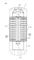
フィルタ装置17は、洗濯槽14内、詳しくは、円周壁14Bの内周面を構成する内周部14Eに単数又は複数設けられる。図7は、径方向内側R1から見たときのフィルタ装置17の正面図である。以下では、図7に示すように径方向内側R1から見たときのフィルタ装置17の姿勢を基準として、フィルタ装置17について説明する。そのため、図7における左右方向をフィルタ装置17の左右方向Xといい、図7における左側を左側X1といい、図7における右側を右側X2という。左右方向Xは、前述した周方向Sと同じ、又は、周方向Sに対する接線方向である。フィルタ装置17は、縦長の全体形状を有する。フィルタ装置17は、洗濯槽14の内周部14Eに取り付けられた縦長のベース30と、径方向内側R1からベース30に対向配置されて洗濯槽14内に露出されるフィルタ31と、径方向Rにおけるベース30とフィルタ31との間に配置されたケース32とを含む。 The filter device 17 is provided in the washing tub 14, specifically, in the inner peripheral portion 14E constituting the inner peripheral surface of the circumferential wall 14B, in one or more units. FIG. 7 is a front view of the filter device 17 as viewed from the radial inner side R1. In the following, the filter device 17 will be described based on the posture of the filter device 17 as viewed from the radial inner side R1 as shown in FIG. 7. Therefore, the left-right direction in FIG. 7 is referred to as the left-right direction X of the filter device 17, the left side in FIG. 7 is referred to as the left side X1, and the right side in FIG. 7 is referred to as the right side X2. The left-right direction X is the same as the circumferential direction S described above, or is a tangential direction to the circumferential direction S. The filter device 17 has a vertically long overall shape. The filter device 17 includes a vertically long base 30 attached to the inner peripheral portion 14E of the washing tub 14, a filter 31 arranged opposite the base 30 from the radial inner side R1 and exposed in the washing tub 14, and a case 32 arranged between the base 30 and the filter 31 in the radial direction R.

図8は、ベース30の正面図である。ベース30において洗濯槽14内に臨む表面部30Aでは、上端部に上開口30Bが設けられ、下端部に下開口30Cが設けられる。上開口30B及び下開口30Cは、ベース30を径方向Rに貫通した貫通穴であってもよいし、径方向外側R2へ窪んだ凹部であってもよい。上開口30Bは、上側Z1へ膨出する半円状に形成され、下開口30Cは、左右方向Xに長手の矩形状に形成される。ベース30には、上開口30B内の上領域に張り出した左右一対の張出部33と、これらの張出部33間に架設された係合部34とが設けられる。これらの張出部33は、正面、つまり径方向内側R1から見て、左右対称な略三角形状又は扇状に形成される。係合部34は、略矩形の小片状であり、その下端は、各張出部33の下端よりも上側Z1に位置して、左右方向Xに延びる。 8 is a front view of the base 30. In the surface portion 30A of the base 30 facing the inside of the washing tub 14, an upper opening 30B is provided at the upper end, and a lower opening 30C is provided at the lower end. The upper opening 30B and the lower opening 30C may be through holes penetrating the base 30 in the radial direction R, or may be recesses recessed toward the radially outer side R2. The upper opening 30B is formed in a semicircular shape that bulges outward Z1, and the lower opening 30C is formed in a rectangular shape elongated in the left-right direction X. The base 30 is provided with a pair of left and right overhanging portions 33 that overhang the upper region in the upper opening 30B, and an engagement portion 34 that is bridged between these overhanging portions 33. These overhanging portions 33 are formed in a substantially triangular or fan-shaped shape that is symmetrical when viewed from the front, that is, from the radially inner side R1. The engagement portion 34 is a small, roughly rectangular piece, with its lower end located on the upper side Z1 above the lower ends of the protrusions 33 and extending in the left-right direction X.

表面部30Aにおいて上開口30Bと下開口30Cとの間の中間領域30Dは、上開口30B及び下開口30Cよりも左右方向Xに幅広の矩形状であって、中間領域30Dのほとんどは、左右方向X及び上下方向Zに沿って略平坦である。表面部30Aにおいて上開口30B、下開口30C及び中間領域30D以外の領域である外縁部30Eは、径方向内側R1へ膨出する湾曲面である。 The intermediate region 30D between the upper opening 30B and the lower opening 30C in the surface portion 30A is rectangular and wider in the left-right direction X than the upper opening 30B and the lower opening 30C, and most of the intermediate region 30D is substantially flat in the left-right direction X and the up-down direction Z. The outer edge portion 30E, which is the area of the surface portion 30A other than the upper opening 30B, the lower opening 30C, and the intermediate region 30D, is a curved surface that bulges radially inward R1.

中間領域30Dにおける左右方向Xの中央には、径方向内側R1へ突出して中間領域30Dの上端と下端とをつなぐように上下方向Zに延びる第1リブ35が設けられる。第1リブ35は、左右方向X及び上下方向Zに沿って平坦であって上下方向Zに細長い端面35Aと、端面35Aから左右方向Xの外側へ広がりながら径方向外側R2に延びる左右一対の湾曲面35Bとを有する。なお、中間領域30Dにおけるベース30の一部を径方向内側R1へV字状に凹ませることによって、このような形状の第1リブ35が形成される(図11参照)。 A first rib 35 is provided in the center of the intermediate region 30D in the left-right direction X, protruding radially inward R1 and extending in the up-down direction Z to connect the upper and lower ends of the intermediate region 30D. The first rib 35 has an end face 35A that is flat along the left-right direction X and the up-down direction Z and is elongated in the up-down direction Z, and a pair of left and right curved faces 35B that extend radially outward R2 while spreading outward from the end face 35A in the left-right direction X. The first rib 35 having such a shape is formed by recessing a part of the base 30 in the intermediate region 30D radially inward R1 in a V-shape (see FIG. 11).

中間領域30Dには、第1リブ35を挟んで横並びに配置された左右一対の流入領域30Fが設けられる。各流入領域30Fには、複数のガイド30Gが上下方向Zに並んで配置される。ほとんどのガイド30Gは、上下方向Zに薄い板状であるが、一部のガイド30Gは、横長の楕円形状であってもよい。以下では、一対の流入領域30Fのうち、左側X1の流入領域30Fを第1流入領域30FAといい、右側X2の流入領域30Fを第2流入領域30FBという。もちろん、第1流入領域30FAと第2流入領域30FBとが逆に配置されてもよい。いずれにせよ、第1流入領域30FAと第2流入領域30FBとは、第1リブ35を基準として左右対称に構成される。 In the intermediate region 30D, a pair of left and right inflow regions 30F are provided, which are arranged side by side with the first rib 35 in between. In each inflow region 30F, a plurality of guides 30G are arranged side by side in the vertical direction Z. Most of the guides 30G are thin plate-shaped in the vertical direction Z, but some of the guides 30G may be horizontally elongated oval shapes. In the following, of the pair of inflow regions 30F, the inflow region 30F on the left side X1 is referred to as the first inflow region 30FA, and the inflow region 30F on the right side X2 is referred to as the second inflow region 30FB. Of course, the first inflow region 30FA and the second inflow region 30FB may be arranged in reverse. In any case, the first inflow region 30FA and the second inflow region 30FB are configured symmetrically with respect to the first rib 35.

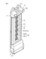
フィルタ31及びケース32のまとまりは、フィルタユニット36を構成する。図9は、分解状態にあるフィルタユニット36の斜視図である。図9では、フィルタ31は、縦長の板状であって、表面部31Aよりも裏面部31Bが主に表れる。フィルタ31の上端部は、上側へ膨出する円弧状に形成される。フィルタ31には、その上端から下側へ窪んでフィルタ31を板厚方向に貫通した凹部31Cが形成される。裏面部31Bの上端部には、上凸部31Dが設けられる。上凸部31Dは、横長の中空体であって、フィルタ31の短手方向における裏面部31Bの全域にわたって配置される。上凸部31Dの上面の中央には、係合部37が設けられる。係合部37は、上側Z1へ延びて湾曲した後に、図9では略水平に延びて一部が凹部31C内に配置される。このような係合部37は、少なくとも上下方向に弾性変形可能である。係合部37の上面には、フィルタ31の短手方向に延びる爪37Aが設けられる。 The filter 31 and the case 32 constitute a filter unit 36. FIG. 9 is a perspective view of the filter unit 36 in a disassembled state. In FIG. 9, the filter 31 is a vertically long plate, and the back surface 31B is mainly shown rather than the front surface 31A. The upper end of the filter 31 is formed in an arc shape that bulges upward. The filter 31 is formed with a recess 31C that is recessed downward from the upper end and penetrates the filter 31 in the plate thickness direction. An upper convex portion 31D is provided at the upper end of the back surface 31B. The upper convex portion 31D is a horizontally long hollow body and is arranged over the entire area of the back surface 31B in the short direction of the filter 31. An engagement portion 37 is provided at the center of the upper surface of the upper convex portion 31D. The engagement portion 37 extends upward Z1 and curves, and then extends approximately horizontally in FIG. 9, with a part of it being arranged within the recess 31C. Such an engagement portion 37 is elastically deformable at least in the vertical direction. A claw 37A extending in the short direction of the filter 31 is provided on the upper surface of the engagement portion 37.

裏面部31Bには、その外縁をなす外周リブ31Eが設けられる。外周リブ31Eの一部は、凹部31C内にも露出されて上凸部31Dの上面に接続される。外周リブ31Eの下端部は、下凸部31Fを構成する。下凸部31Fは、裏面部31Bの下縁に沿ってフィルタ31の短手方向に延びる下板31FAと、短手方向における下板31FAの両端から立ち上がった一対の側板31FBとを有する。 The back surface portion 31B is provided with a peripheral rib 31E that forms its outer edge. A portion of the peripheral rib 31E is exposed in the recess 31C and is connected to the upper surface of the upper protrusion 31D. The lower end of the peripheral rib 31E forms the lower protrusion 31F. The lower protrusion 31F has a lower plate 31FA that extends in the short direction of the filter 31 along the lower edge of the back surface portion 31B, and a pair of side plates 31FB that rise from both ends of the lower plate 31FA in the short direction.

裏面部31Bにおいて上凸部31Dと下凸部31Fとの間の中間領域31Gには、フィルタ31の長手方向つまり上下方向に延びる第2リブ38が設けられる。第2リブ38は、フィルタ31の短手方向における中間領域31Gの中央に配置され、上凸部31Dと下凸部31Fの下板31FAとの間に架設される。 A second rib 38 extending in the longitudinal direction of the filter 31, i.e., the up-down direction, is provided in the intermediate region 31G between the upper convex portion 31D and the lower convex portion 31F on the back surface portion 31B. The second rib 38 is disposed in the center of the intermediate region 31G in the lateral direction of the filter 31, and is installed between the upper convex portion 31D and the lower plate 31FA of the lower convex portion 31F.

中間領域31Gには、第2リブ38を挟んで横並びに配置された一対つまり2列の捕獲領域31Hが設けられる。以下では、図9における右側の捕獲領域31Hを第1捕獲領域31HAといい、図9における左側の捕獲領域31Hを第2捕獲領域31HBという。もちろん、第1捕獲領域31HAと第2捕獲領域31HBとが逆に配置されてもよい。いずれにせよ、第1捕獲領域31HAと第2捕獲領域31HBとは、第2リブ38を基準として左右対称に構成される。各捕獲領域31Hには、上下方向に等間隔で並ぶ複数の貫通穴31Iが設けられる。各貫通穴31Iの一例は、四隅が丸められた横長の矩形状である。各貫通穴31Iには、メッシュシート39が貫通穴31Iを塞ぐように取り付けられる。メッシュシート39には、微小な貫通穴であるフィルタ穴39Aが無数に形成される。第1捕獲領域31HAの貫通穴31Iに設けられたメッシュシート39は、第1捕獲領域31HAの一部であり、第2捕獲領域31HBの貫通穴31Iに設けられたメッシュシート39は、第2捕獲領域31HBの一部である。そのため、各捕獲領域31Hには、複数のフィルタ穴39Aが分布する。なお、前述した図7では、メッシュシート39の図示が省略される。また、メッシュシート39の代りに、各捕獲領域31HAに一体形成された格子を用いてもよく、この場合には、格子の隙間がフィルタ穴39Aとして機能する。 In the intermediate region 31G, a pair of capture regions 31H, i.e., two rows, are provided, arranged side by side with the second rib 38 between them. In the following, the capture region 31H on the right side in FIG. 9 is referred to as the first capture region 31HA, and the capture region 31H on the left side in FIG. 9 is referred to as the second capture region 31HB. Of course, the first capture region 31HA and the second capture region 31HB may be arranged in reverse. In any case, the first capture region 31HA and the second capture region 31HB are configured symmetrically with respect to the second rib 38. Each capture region 31H is provided with a plurality of through holes 31I arranged at equal intervals in the vertical direction. An example of each through hole 31I is a horizontally long rectangular shape with rounded corners. A mesh sheet 39 is attached to each through hole 31I so as to cover the through hole 31I. Countless filter holes 39A, which are minute through holes, are formed in the mesh sheet 39. The mesh sheet 39 provided in the through hole 31I of the first capture area 31HA is part of the first capture area 31HA, and the mesh sheet 39 provided in the through hole 31I of the second capture area 31HB is part of the second capture area 31HB. Therefore, a plurality of filter holes 39A are distributed in each capture area 31H. Note that the mesh sheet 39 is not shown in FIG. 7. Also, instead of the mesh sheet 39, a lattice formed integrally with each capture area 31HA may be used, in which case the gaps in the lattice function as the filter holes 39A.

ケース32は、長方形の板状である。ケース32の中央には、ケース32の長手方向に延びてケース32を貫通した中継口32Aが設けられる。図9での姿勢におけるケース32の上面部には、その外縁の全域にわたって立ち上がった外周リブ32Bと、中継口32Aの全域を縁取りつつ立ち上がった内周リブ32Cと、中継口32Aを挟んでケース32の長手方向に延びる溝状をなす一対の収容室32Dが設けられる。ケース32の長手方向における一端部、図9では右手前の端部において、外周リブ32Bの一部と内周リブ32Cの一部とが一体化される。 The case 32 is a rectangular plate. In the center of the case 32, a relay port 32A is provided, which extends in the longitudinal direction of the case 32 and penetrates the case 32. On the upper surface of the case 32 in the position shown in FIG. 9, an outer peripheral rib 32B that rises along the entire outer edge, an inner peripheral rib 32C that rises while bordering the entire relay port 32A, and a pair of groove-shaped storage chambers 32D that extend in the longitudinal direction of the case 32 on either side of the relay port 32A are provided. At one end of the case 32 in the longitudinal direction, which is the end on the front right in FIG. 9, a part of the outer peripheral rib 32B and a part of the inner peripheral rib 32C are integrated.

図9における右奥側の収容室32Dを第1収容室32DAといい、図9における左手前側の収容室32Dを第2収容室32DBという。もちろん、第1収容室32DAと第2収容室32DBとが逆に配置されてもよい。各収容室32Dは、外周リブ32Bと内周リブ32Cとによって取り囲まれる。図9での姿勢におけるケース32の上面部には、第1収容室32DA及び第2収容室32DBの端部同士、図9では左奥前の端部同士をつなぐ溝状の第3収容室32Eが設けられる。 The storage chamber 32D on the right rear side in FIG. 9 is referred to as the first storage chamber 32DA, and the storage chamber 32D on the left front side in FIG. 9 is referred to as the second storage chamber 32DB. Of course, the first storage chamber 32DA and the second storage chamber 32DB may be arranged in reverse. Each storage chamber 32D is surrounded by an outer peripheral rib 32B and an inner peripheral rib 32C. A groove-shaped third storage chamber 32E that connects the ends of the first storage chamber 32DA and the second storage chamber 32DB, or the ends of the left rear front in FIG. 9, is provided on the upper surface of the case 32 in the position shown in FIG. 9.

ケース32の中継口32A内には、ケース32の長手方向に延びる第3リブ40が設けられる。これにより、中継口32Aは、第1収容室32DA側の第1中継口32AAと、第2収容室32DB側の第2中継口32ABとに二分される。第1中継口32AAと第2中継口32ABとは、横並びに配置され、第3リブ40は、第1中継口32AAと第2中継口32ABとの間に配置される。第1中継口32AAと第2中継口32ABとは、第3リブ40を基準として左右対称に構成される。中継口32A内には、ケース32の短手方向に延びる複数の横リブ41が設けられる。これらの横リブ41は、ケース32の長手方向に等間隔で並び、最寄りの内周リブ32Cと第3リブ40との間に架設される。 A third rib 40 extending in the longitudinal direction of the case 32 is provided in the relay port 32A of the case 32. This divides the relay port 32A into a first relay port 32AA on the first storage chamber 32DA side and a second relay port 32AB on the second storage chamber 32DB side. The first relay port 32AA and the second relay port 32AB are arranged side by side, and the third rib 40 is arranged between the first relay port 32AA and the second relay port 32AB. The first relay port 32AA and the second relay port 32AB are configured symmetrically with respect to the third rib 40. A plurality of horizontal ribs 41 extending in the lateral direction of the case 32 are provided in the relay port 32A. These horizontal ribs 41 are arranged at equal intervals in the longitudinal direction of the case 32 and are installed between the nearest inner peripheral rib 32C and the third rib 40.

ケース32において第3収容室32E側の端部は、フィルタ31の下凸部31Fにおける一対の側板31FBの間に配置される。ケース32の当該端部は、ケース32の短手方向に延びる回動軸42を介して各側板31FBに連結される。ケース32は、フィルタ31に対して回動軸42まわりに相対回動可能である。図9におけるケース32は、分解位置にあり、このとき、ケース32の第3リブ40がフィルタ31の第2リブ38から離れた状態にある。なお、分解位置にあるケース32は、下凸部31Fの下板31FAに載った状態にあるので、下側へこれ以上回動してフィルタ31からさらに離れることはない。 The end of the case 32 on the third storage chamber 32E side is disposed between a pair of side plates 31FB in the lower convex portion 31F of the filter 31. This end of the case 32 is connected to each side plate 31FB via a pivot shaft 42 extending in the short direction of the case 32. The case 32 can rotate about the pivot shaft 42 relative to the filter 31. The case 32 in FIG. 9 is in the disassembled position, and at this time, the third rib 40 of the case 32 is separated from the second rib 38 of the filter 31. Note that the case 32 in the disassembled position is resting on the lower plate 31FA of the lower convex portion 31F, so it cannot rotate further downward and separate from the filter 31.

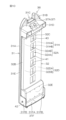
使用者が、分解位置にあるケース32を回動軸42まわりに回動させてフィルタ31に接近させると、図10に示すように、ケース32が組付位置に配置されてフィルタユニット36が完成する。このように、ケース32は、分解位置と組付位置との間で回動可能である。組付位置にあるケース32の長手方向は、フィルタ31の長手方向と一致し、ケース32は、フィルタ31の上凸部31Dと下凸部31Fの下板31FAとの間に配置される。また、ケース32の外周リブ32Bは、フィルタ31の外周リブ31Eの内側に配置される。使用者は、ケース32を分解位置まで回動させることによってフィルタユニット36を分解することができる(図9参照)。なお、フィルタユニット36の組立や分解の際、使用者は、ケース32でなくフィルタ31を回動させてもよいし、フィルタ31及びケース32の両方を回動させてもよい。 When the user rotates the case 32 in the disassembly position around the rotation shaft 42 to bring it close to the filter 31, as shown in FIG. 10, the case 32 is placed in the assembly position and the filter unit 36 is completed. In this way, the case 32 can be rotated between the disassembly position and the assembly position. The longitudinal direction of the case 32 in the assembly position coincides with the longitudinal direction of the filter 31, and the case 32 is placed between the upper convex portion 31D and the lower plate 31FA of the lower convex portion 31F of the filter 31. In addition, the outer peripheral rib 32B of the case 32 is placed inside the outer peripheral rib 31E of the filter 31. The user can disassemble the filter unit 36 by rotating the case 32 to the disassembly position (see FIG. 9). When assembling or disassembling the filter unit 36, the user may rotate the filter 31 instead of the case 32, or may rotate both the filter 31 and the case 32.

使用者が、完成したフィルタユニット36をベース30に組み付けてフィルタ31の上凸部31D及び下凸部31Fをベース30の上開口30B及び下開口30C(図8参照)にそれぞれ嵌め込む。すると、図7に示すように、フィルタユニット36がベース30に装着されることによって、フィルタ装置17が完成する。このとき、フィルタ31及びケース32のそれぞれの長手方向は、上下方向Zと一致し、フィルタ31及びケース32のそれぞれの短手方向は、左右方向Xつまり周方向Sと一致する。フィルタ31の係合部37の爪37A(図9参照)がベース30の係合部34(図8参照)に径方向外側R2から係合することにより、ベース30からのフィルタユニット36の脱落が防止される。なお、使用者は、係合部37を下側Z2へ弾性変形させて爪37Aを係合部34から外すと、ベース30からのフィルタユニット36を離脱させることができる。 The user assembles the completed filter unit 36 to the base 30 and fits the upper convex portion 31D and the lower convex portion 31F of the filter 31 into the upper opening 30B and the lower opening 30C (see FIG. 8) of the base 30, respectively. Then, as shown in FIG. 7, the filter unit 36 is attached to the base 30, completing the filter device 17. At this time, the longitudinal directions of the filter 31 and the case 32 coincide with the vertical direction Z, and the lateral directions of the filter 31 and the case 32 coincide with the horizontal direction X, i.e., the circumferential direction S. The claws 37A (see FIG. 9) of the engagement portion 37 of the filter 31 engage with the engagement portion 34 (see FIG. 8) of the base 30 from the radial outside R2, thereby preventing the filter unit 36 from falling off the base 30. The user can detach the filter unit 36 from the base 30 by elastically deforming the engagement portion 37 downward Z2 to disengage the claws 37A from the engagement portion 34.

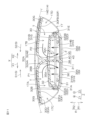
図7のB-B矢視断面図である図11に示すように、完成したフィルタ装置17では、ベース30の第1流入領域30FAと、フィルタ31の第1捕獲領域31HAと、ケース32の第1収容室32DA及び第1中継口32AAとが、左右方向Xにおいて同じ位置に配置される。第1収容室32DA及び第1中継口32AAは、径方向外側R2から第1捕獲領域31HAに対向する。第1収容室32DAは、第1捕獲領域31HAから径方向外側R2つまりベース30側へ窪んだ状態にある。また、ベース30の第2流入領域30FBと、フィルタ31の第2捕獲領域31HBと、ケース32の第2収容室32DB及び第2中継口32ABとが、左右方向Xにおいて同じ位置に配置される。第2収容室32DB及び第2中継口32ABは、径方向外側R2から第2捕獲領域31HBに対向する。第2収容室32DBは、第2捕獲領域31HBから径方向外側R2へ窪んだ状態にある。 As shown in FIG. 11, which is a cross-sectional view of the arrows B-B in FIG. 7, in the completed filter device 17, the first inflow area 30FA of the base 30, the first capture area 31HA of the filter 31, and the first storage chamber 32DA and first relay port 32AA of the case 32 are arranged at the same position in the left-right direction X. The first storage chamber 32DA and the first relay port 32AA face the first capture area 31HA from the radial outside R2. The first storage chamber 32DA is recessed from the first capture area 31HA toward the radial outside R2, that is, toward the base 30. In addition, the second inflow area 30FB of the base 30, the second capture area 31HB of the filter 31, and the second storage chamber 32DB and second relay port 32AB of the case 32 are arranged at the same position in the left-right direction X. The second storage chamber 32DB and second relay port 32AB face the second capture area 31HB from the radial outside R2. The second storage chamber 32DB is recessed radially outward R2 from the second capture region 31HB.

また、ベース30の第1リブ35と、フィルタ31の第2リブ38と、ケース32の第3リブ40とは、左右方向Xにおいて同じ位置に配置される。第1リブ35の端面35Aは、径方向外側R2から第3リブ40に接触する。第2リブ38は、第1リブ35側つまり径方向外側R2へ突出して、径方向内側R1から第3リブ40に接触する。これにより、第3リブ40が、第1リブ35と第2リブ38とによって径方向Rの両側から挟まれる。第1リブ35と第2リブ38と第3リブ40とが一体化されて、上下方向Z及び径方向Rに延びる一つの隔壁43を構成する。これにより、フィルタ装置17の内部空間は、隔壁43を挟んで横並びに配置された第1内部空間17A及び第2内部空間17Bに二分される。第1内部空間17Aは、本実施形態では第2内部空間17Bの左側X1に配置されるが、逆に配置されてもよい。 The first rib 35 of the base 30, the second rib 38 of the filter 31, and the third rib 40 of the case 32 are arranged at the same position in the left-right direction X. The end face 35A of the first rib 35 contacts the third rib 40 from the radial outer side R2. The second rib 38 protrudes toward the first rib 35 side, that is, the radial outer side R2, and contacts the third rib 40 from the radial inner side R1. As a result, the third rib 40 is sandwiched between the first rib 35 and the second rib 38 from both sides in the radial direction R. The first rib 35, the second rib 38, and the third rib 40 are integrated to form a single partition wall 43 extending in the vertical direction Z and the radial direction R. As a result, the internal space of the filter device 17 is divided into a first internal space 17A and a second internal space 17B arranged side by side with the partition wall 43 in between. In this embodiment, the first internal space 17A is located on the left side X1 of the second internal space 17B, but the locations may be reversed.

第1内部空間17Aは、ベース30の第1流入領域30FAと、フィルタ31の第1捕獲領域31HAと、ケース32の第1収容室32DA及び第1中継口32AAとによって構成される。第1中継口32AAは、第1流入領域30FAと、第1捕獲領域31HAとを中継する。第2内部空間17Bは、ベース30の第2流入領域30FBと、フィルタ31の第2捕獲領域31HBと、ケース32の第2収容室32DB及び第2中継口32ABとによって構成される。第2中継口32ABは、第2流入領域30FBと、第2捕獲領域31HBとを中継する。 The first internal space 17A is composed of the first inflow area 30FA of the base 30, the first capture area 31HA of the filter 31, the first storage chamber 32DA of the case 32, and the first relay port 32AA. The first relay port 32AA relays between the first inflow area 30FA and the first capture area 31HA. The second internal space 17B is composed of the second inflow area 30FB of the base 30, the second capture area 31HB of the filter 31, the second storage chamber 32DB of the case 32, and the second relay port 32AB. The second relay port 32AB relays between the second inflow area 30FB and the second capture area 31HB.

洗濯槽14の内周部14Eにフィルタ装置17が取り付けられた洗濯機11の洗濯運転やすすぎ運転では、パルセータ16が回転することによって洗濯槽14内に水流が発生する。パルセータ16が平面視で時計回りに正回転すると、洗濯槽14内の水が、周方向Sにおける第1周方向S1に流れて、第1流入領域30FAとケース32との間のスペースに流入する。当該スペースを第1流入領域30FAの一部とみなすことができ、当該スペースの左端をフィルタ装置17の第1流入口17Cといってもよい。パルセータ16が平面視で反時計回りに逆回転すると、洗濯槽14内の水が、周方向Sにおける第2周方向S2に流れて、第2流入領域30FBとケース32との間のスペースに流入する。当該スペースを第2流入領域30FBの一部とみなすことができ、当該スペースの右端をフィルタ装置17の第2流入口17Dといってもよい。第1周方向S1は、右側X2と一致し、第2周方向S2は、左側X1と一致する。なお、パルセータ16でなく、洗濯槽14が回転することによって水流が発生してもよい。各流入領域30Fでは、ガイド30Gが左右方向Xにおける外側へ偏って配置されるので、ガイド30Gと隔壁43との間には、水を取り込むための比較的広い空間Tが確保される。 In the washing operation or rinsing operation of the washing machine 11 in which the filter device 17 is attached to the inner periphery 14E of the washing tub 14, the pulsator 16 rotates to generate a water flow in the washing tub 14. When the pulsator 16 rotates clockwise in a plan view, the water in the washing tub 14 flows in the first circumferential direction S1 in the circumferential direction S and flows into the space between the first inflow area 30FA and the case 32. This space can be considered as a part of the first inflow area 30FA, and the left end of the space can be called the first inlet 17C of the filter device 17. When the pulsator 16 rotates counterclockwise in a plan view, the water in the washing tub 14 flows in the second circumferential direction S2 in the circumferential direction S and flows into the space between the second inflow area 30FB and the case 32. This space can be considered as a part of the second inflow area 30FB, and the right end of the space can be called the second inlet 17D of the filter device 17. The first circumferential direction S1 coincides with the right side X2, and the second circumferential direction S2 coincides with the left side X1. The water flow may be generated by the rotation of the washing tub 14 instead of the pulsator 16. In each inflow area 30F, the guide 30G is positioned outward in the left-right direction X, so that a relatively large space T for taking in water is secured between the guide 30G and the partition wall 43.

第1流入領域30FAに流入した水は、矢印P1で示すように、第1内部空間17Aにおいて、隔壁43の左側面にガイドされて第1中継口32AAを通って第1捕獲領域31HAに到達し、第1捕獲領域31HAにおけるメッシュシート39のフィルタ穴39Aから径方向内側R1へ流出して洗濯槽14内に戻る。流出する水に含まれる糸くずや埃などの異物Fは、第1捕獲領域31HAにおいて捕獲される。第2流入領域30FBに流入した水は、矢印P2で示すように、第2内部空間17Bにおいて、隔壁43の右側面にガイドされて第2中継口32ABを通って第2捕獲領域31HBに到達し、第2捕獲領域31HBにおけるメッシュシート39のフィルタ穴39Aから径方向内側R1へ流出して洗濯槽14内に戻る。流出する水に含まれる異物Fは、第2捕獲領域31HBにおいて捕獲される。図11では、各捕獲領域31Hによって捕獲された異物Fが、太い点線によって図示される。 As shown by arrow P1, the water that flows into the first inflow area 30FA is guided by the left side of the partition 43 in the first internal space 17A, passes through the first relay port 32AA, and reaches the first capture area 31HA, and flows out from the filter hole 39A of the mesh sheet 39 in the first capture area 31HA to the radially inward R1 and returns to the washing tub 14. Foreign matter F such as lint and dust contained in the outflowing water is captured in the first capture area 31HA. As shown by arrow P2, the water that flows into the second inflow area 30FB is guided by the right side of the partition 43 in the second internal space 17B, passes through the second relay port 32AB, and reaches the second capture area 31HB, and flows out from the filter hole 39A of the mesh sheet 39 in the second capture area 31HB to the radially inward R1 and returns to the washing tub 14. Foreign matter F contained in the outflowing water is captured in the second capture area 31HB. In FIG. 11, the foreign matter F captured by each capture region 31H is shown by a thick dotted line.

以上のように、フィルタ装置17は、ベース30、フィルタ31及びケース32の3つという少ない部品点数で構成される。フィルタ装置17では、ベース30の第1リブ35とフィルタ31の第2リブ38とによって、ベース30とフィルタ31との間のケース32の第3リブ40が挟まれることにより、これらのリブが一体化されて隔壁43を構成してフィルタ装置17の全体を補強するので、強度の向上を図れる。 As described above, the filter device 17 is composed of only three parts: the base 30, the filter 31, and the case 32. In the filter device 17, the third rib 40 of the case 32 between the base 30 and the filter 31 is sandwiched between the first rib 35 of the base 30 and the second rib 38 of the filter 31, and these ribs are integrated to form a partition 43 that reinforces the entire filter device 17, thereby improving its strength.

そして、フィルタ装置17の内部空間を隔壁43によって第1内部空間17Aと第2内部空間17Bとに二分して可動部品を無くし、洗濯槽14内の水流の向きに応じて、第1内部空間17A及び第2内部空間17Bのどちらかで異物Fを漏れなく捕獲することにより、フィルタ装置17は、安定した状態で異物Fを捕獲できるので、異物Fの捕獲効率の向上を図れる。 The internal space of the filter device 17 is divided into a first internal space 17A and a second internal space 17B by a partition 43, eliminating any moving parts, and foreign matter F is captured without leakage in either the first internal space 17A or the second internal space 17B depending on the direction of the water flow in the washing tub 14. This allows the filter device 17 to capture foreign matter F in a stable state, thereby improving the efficiency of capturing foreign matter F.

洗濯機11の脱水運転において洗濯槽14が回転すると、第1捕獲領域31HA及び第2捕獲領域31HBのそれぞれに溜まった異物Fは、遠心力が作用することによって径方向外側R2へ移動しようとする。第1捕獲領域31HAからの異物Fは、矢印Q1に示すように、ケース32における第1収容室32DAに受け入れられ、第2捕獲領域31HBからの異物Fは、矢印Q2に示すように、ケース32における第2収容室32DBに受け入れられる。これにより、フィルタ装置17がせっかく捕獲した異物Fがフィルタ装置17外に漏れることを防止できるので、異物Fの捕獲効率の一層の向上を図れる。なお、第1収容室32DAや第2収容室32DBが一杯になっても、これらの下側Z2に位置する第3収容室32Eが異物Fを収容することができる。 When the washing tub 14 rotates during the spin cycle of the washing machine 11, the foreign objects F accumulated in the first capture area 31HA and the second capture area 31HB tend to move radially outward R2 due to the action of centrifugal force. The foreign objects F from the first capture area 31HA are received in the first storage chamber 32DA in the case 32 as shown by the arrow Q1, and the foreign objects F from the second capture area 31HB are received in the second storage chamber 32DB in the case 32 as shown by the arrow Q2. This prevents the foreign objects F captured by the filter device 17 from leaking out of the filter device 17, thereby further improving the efficiency of capturing the foreign objects F. Even if the first storage chamber 32DA or the second storage chamber 32DB is full, the third storage chamber 32E located below them Z2 can still store the foreign objects F.

そして、フィルタ31及びケース32によるフィルタユニット36をベース30に対して着脱させることができるので、使用者は、メンテナンスのためにフィルタユニット36をベース30から取り外して分解すれば、フィルタ装置17が捕獲した異物Fを除去することができる(図9参照)。その後、使用者は、フィルタユニット36を完成させてベース30に取り付けることによってフィルタ装置17を使用可能な状態に戻すことができる。 The filter unit 36 consisting of the filter 31 and the case 32 can be attached and detached to the base 30, so that the user can remove the filter unit 36 from the base 30 and disassemble it for maintenance, thereby removing the foreign matter F captured by the filter device 17 (see FIG. 9). The user can then complete the filter unit 36 and attach it to the base 30, restoring the filter device 17 to a usable state.

本発明は、以上に説明した実施形態に限定されるものではなく、請求項に記載の範囲内において種々の変更が可能である。 The present invention is not limited to the embodiments described above, and various modifications are possible within the scope of the claims.

11 洗濯機
14 洗濯槽
14A 内周部
17 フィルタ装置
30 ベース
30A 表面部
30FA 第1流入領域
30FB 第2流入領域
31 フィルタ
31HA 第1捕獲領域
31HB 第2捕獲領域
32 ケース
32AA 第1中継口
32AB 第2中継口
32DA 第1収容室
32DB 第2収容室
35 第1リブ
36 フィルタユニット
38 第2リブ
39A フィルタ穴
40 第3リブ
42 回動軸
F 異物
L 洗濯物
REFERENCE SIGNS LIST 11 washing machine 14 washing tub 14A inner periphery 17 filter device 30 base 30A surface 30FA first inflow area 30FB second inflow area 31 filter 31HA first capture area 31HB second capture area 32 case 32AA first relay port 32AB second relay port 32DA first storage chamber 32DB second storage chamber 35 first rib 36 filter unit 38 second rib 39A filter hole 40 third rib 42 pivot shaft F foreign object L laundry

Claims (4)

洗濯機において洗濯物を収容して水が溜められる洗濯槽の内周部に取り付けられるベースであって、前記洗濯槽内に臨む表面部と、前記表面部に配置された第1リブと、前記表面部において前記第1リブを挟んで横並びに配置された第1流入領域及び第2流入領域とが設けられたベースと、
前記ベースに対向配置されて前記洗濯槽内に露出されるフィルタであって、前記第1リブ側へ突出した第2リブと、前記第2リブを挟んで横並びに配置された第1捕獲領域及び第2捕獲領域と、前記第1捕獲領域及び第2捕獲領域のそれぞれに分布する複数のフィルタ穴とが設けられたフィルタと、
前記ベースと前記フィルタとの間に配置されるケースであって、前記第1流入領域と前記第1捕獲領域とを中継する第1中継口と、前記第2流入領域と前記第2捕獲領域とを中継し、前記第1中継口と横並びに配置された第2中継口と、前記第1中継口と前記第2中継口との間に配置され、前記第1リブと前記第2リブとによって挟まれる第3リブとが設けられたケースと、を含み、
前記洗濯槽内において前記第1流入領域に流入して前記第1中継口を通って前記第1捕獲領域の前記フィルタ穴から流出する水に含まれる異物を前記第1捕獲領域において捕獲したり、前記洗濯槽内において前記第2流入領域に流入して前記第2中継口を通って前記第2捕獲領域の前記フィルタ穴から流出する水に含まれる異物を前記第2捕獲領域において捕獲したりする、フィルタ装置。
A base is attached to an inner periphery of a washing tub in which laundry is stored and water is collected in a washing machine, the base being provided with a surface portion facing the inside of the washing tub, a first rib arranged on the surface portion, and a first inflow area and a second inflow area arranged side by side on both sides of the first rib on the surface portion;
a filter disposed opposite the base and exposed in the washing tub, the filter including a second rib protruding toward the first rib, a first capture area and a second capture area disposed side by side with the second rib therebetween, and a plurality of filter holes distributed in each of the first capture area and the second capture area;
a case disposed between the base and the filter, the case including a first relay port that relays between the first inflow region and the first capture region, a second relay port that relays between the second inflow region and the second capture region and is disposed side by side with the first relay port, and a third rib that is disposed between the first relay port and the second relay port and is sandwiched between the first rib and the second rib,
A filter device that captures foreign matter contained in water that flows into the first inlet region in the washing tub and flows out of the filter hole in the first capture region through the first relay port in the first capture region, and captures foreign matter contained in water that flows into the second inlet region in the washing tub and flows out of the filter hole in the second capture region through the second relay port in the second capture region.
前記ケースには、前記第1捕獲領域から前記ベース側へ窪んで前記第1捕獲領域からの異物を受け入れる第1収容室と、前記第2捕獲領域から前記ベース側へ窪んで前記第2捕獲領域からの異物を受け入れる第2収容室とが設けられる、請求項1に記載のフィルタ装置。 The filter device according to claim 1, wherein the case is provided with a first storage chamber recessed from the first capture region toward the base side to receive foreign matter from the first capture region, and a second storage chamber recessed from the second capture region toward the base side to receive foreign matter from the second capture region. 前記フィルタと前記ケースとは、回動軸を介して連結され、
前記ケースは、前記第3リブが前記第2リブに接触する組付位置と、前記第3リブが前記第2リブから離れる分解位置との間で、前記フィルタに対して前記回動軸まわりに相対回動可能であり、
前記ケースが組付位置にあるときの前記フィルタ及び前記ケースは、完成したフィルタユニットを構成して、前記ベースに対して着脱可能である、請求項1又は2に記載のフィルタ装置。
The filter and the case are connected via a rotating shaft,
the case is rotatable about the rotation axis relative to the filter between an assembly position in which the third rib contacts the second rib and a disassembly position in which the third rib is separated from the second rib,
3. The filter device according to claim 1, wherein the filter and the case constitute a completed filter unit when the case is in the assembled position and are detachable from the base.
洗濯物を収容して水が溜められる洗濯槽と、
前記洗濯槽の内周部に取り付けられた請求項1~3のいずれか一項に記載のフィルタ装置と、を含む、洗濯機。
A washing tub that can hold laundry and water;
A washing machine comprising: the filter device according to any one of claims 1 to 3 attached to an inner periphery of the washing tub.
JP2021099009A 2021-06-14 2021-06-14 Filter device and washing machine Active JP7578956B2 (en)

Priority Applications (3)

Application Number Priority Date Filing Date Title
JP2021099009A JP7578956B2 (en) 2021-06-14 2021-06-14 Filter device and washing machine
PCT/CN2022/097658 WO2022262622A1 (en) 2021-06-14 2022-06-08 Filtering device and washing machine
CN202280042591.1A CN117500969A (en) 2021-06-14 2022-06-08 Filtration device and washing machine

Applications Claiming Priority (1)

Application Number Priority Date Filing Date Title
JP2021099009A JP7578956B2 (en) 2021-06-14 2021-06-14 Filter device and washing machine

Publications (2)

Publication Number Publication Date
JP2022190605A JP2022190605A (en) 2022-12-26
JP7578956B2 true JP7578956B2 (en) 2024-11-07

Family

ID=84525946

Family Applications (1)

Application Number Title Priority Date Filing Date
JP2021099009A Active JP7578956B2 (en) 2021-06-14 2021-06-14 Filter device and washing machine

Country Status (3)

Country Link
JP (1) JP7578956B2 (en)
CN (1) CN117500969A (en)
WO (1) WO2022262622A1 (en)

Families Citing this family (1)

* Cited by examiner, † Cited by third party
Publication number Priority date Publication date Assignee Title
WO2025227649A1 (en) * 2024-04-29 2025-11-06 海信冰箱有限公司 Impeller washing machine

Citations (2)

* Cited by examiner, † Cited by third party
Publication number Priority date Publication date Assignee Title
US20180038031A1 (en) 2016-08-08 2018-02-08 Lg Electronics Inc. Laundry treating apparatus
CN209523037U (en) 2018-12-13 2019-10-22 无锡小天鹅电器有限公司 The cover plate assembly and clothes treatment device of clothes treatment device

Family Cites Families (6)

* Cited by examiner, † Cited by third party
Publication number Priority date Publication date Assignee Title
KR100220745B1 (en) * 1997-07-21 1999-09-15 윤종용 The filter apparatus of a washing machine
WO2005118940A1 (en) * 2004-06-01 2005-12-15 Lg Electronics, Inc. A laundry machine and lint filter thereof
CN101046054B (en) * 2006-03-30 2010-04-07 江门市洗衣机厂 Filter for impeller or agitator type washing machine and the washing machine therewith
CN106283536B (en) * 2015-06-23 2019-10-01 青岛海尔洗衣机有限公司 A kind of omnibearing line bits filtering device and washing machine
JP6932188B2 (en) * 2017-06-01 2021-09-08 シャープ株式会社 Washing machine
CN112064300B (en) * 2019-06-10 2023-01-24 青岛海尔洗衣机有限公司 A washing machine lint filter and a washing machine using the same

Patent Citations (2)

* Cited by examiner, † Cited by third party
Publication number Priority date Publication date Assignee Title
US20180038031A1 (en) 2016-08-08 2018-02-08 Lg Electronics Inc. Laundry treating apparatus
CN209523037U (en) 2018-12-13 2019-10-22 无锡小天鹅电器有限公司 The cover plate assembly and clothes treatment device of clothes treatment device

Also Published As

Publication number Publication date
CN117500969A (en) 2024-02-02
JP2022190605A (en) 2022-12-26
WO2022262622A1 (en) 2022-12-22

Similar Documents

Publication Publication Date Title
KR102147819B1 (en) Washing Machine and Control Method Thereof
JP4976276B2 (en) Drum assembly for washing machine and manufacturing method thereof
US4848105A (en) Self-cleaning lint filter for clothes washing machine
US20080216523A1 (en) Foreign materials filtering apparatus
KR101268222B1 (en) Washing machine
CN102560955A (en) Drum type washing machine and drum type washing and drying all-in-one machine
JP5931384B2 (en) Washing machine
JP7578956B2 (en) Filter device and washing machine
US4125003A (en) Sump strainer for tumbler washing machine
JP2010012143A (en) Washing machine
KR102577544B1 (en) A Laundry Treatment Machine
KR102694109B1 (en) sensor module and clothes treatment apparatus having the same
KR20180015872A (en) Washing Machine
JP4710539B2 (en) Drum washing machine
KR102421544B1 (en) Washing machine
JP7126152B2 (en) washing machine
JP2018042622A (en) Washing machine
JP2010136904A (en) Dewatering-cum-washing machine
JP2017144123A (en) Washing machine
CN114729494B (en) Fluid channel switching pump
JP6294347B2 (en) Detachable structure for attaching and detaching parts to the inner peripheral part of the washing tub
US7415846B2 (en) Button assembly and washing machine having the same
JP2018078916A (en) Drum washing machine
KR20220112503A (en) Washing machine
JP6742284B2 (en) Filter unit and washing machine having filter unit

Legal Events

Date Code Title Description
A621 Written request for application examination

Free format text: JAPANESE INTERMEDIATE CODE: A621

Effective date: 20240411

A977 Report on retrieval

Free format text: JAPANESE INTERMEDIATE CODE: A971007

Effective date: 20240925

TRDD Decision of grant or rejection written
A01 Written decision to grant a patent or to grant a registration (utility model)

Free format text: JAPANESE INTERMEDIATE CODE: A01

Effective date: 20241003

A61 First payment of annual fees (during grant procedure)

Free format text: JAPANESE INTERMEDIATE CODE: A61

Effective date: 20241017

R150 Certificate of patent or registration of utility model

Ref document number: 7578956

Country of ref document: JP

Free format text: JAPANESE INTERMEDIATE CODE: R150