JP7574635B2 - Power supply control device, power supply control method, and power supply system - Google Patents
Power supply control device, power supply control method, and power supply system Download PDFInfo
- Publication number
- JP7574635B2 JP7574635B2 JP2020207760A JP2020207760A JP7574635B2 JP 7574635 B2 JP7574635 B2 JP 7574635B2 JP 2020207760 A JP2020207760 A JP 2020207760A JP 2020207760 A JP2020207760 A JP 2020207760A JP 7574635 B2 JP7574635 B2 JP 7574635B2
- Authority
- JP
- Japan
- Prior art keywords
- power
- generation device
- power generation
- decrease
- power supply
- Prior art date
- Legal status (The legal status is an assumption and is not a legal conclusion. Google has not performed a legal analysis and makes no representation as to the accuracy of the status listed.)
- Active
Links
- 238000000034 method Methods 0.000 title claims description 20
- 238000010248 power generation Methods 0.000 claims description 351
- 230000007423 decrease Effects 0.000 claims description 144
- 238000004146 energy storage Methods 0.000 claims description 87
- 238000009434 installation Methods 0.000 claims description 36
- 230000005855 radiation Effects 0.000 description 9
- 238000004891 communication Methods 0.000 description 7
- 230000008859 change Effects 0.000 description 5
- 238000010586 diagram Methods 0.000 description 5
- 230000008569 process Effects 0.000 description 5
- 230000009467 reduction Effects 0.000 description 3
- 230000003247 decreasing effect Effects 0.000 description 2
- 230000000694 effects Effects 0.000 description 2
- 230000009471 action Effects 0.000 description 1
- 230000000903 blocking effect Effects 0.000 description 1
- 239000003990 capacitor Substances 0.000 description 1
- 238000005266 casting Methods 0.000 description 1
- 230000006866 deterioration Effects 0.000 description 1
- 230000005611 electricity Effects 0.000 description 1
- 239000000446 fuel Substances 0.000 description 1
- 230000006870 function Effects 0.000 description 1
- 230000004044 response Effects 0.000 description 1
- 239000004065 semiconductor Substances 0.000 description 1
Images


Landscapes
- Supply And Distribution Of Alternating Current (AREA)
- Charge And Discharge Circuits For Batteries Or The Like (AREA)
Description
本発明は、電力供給制御装置、電力供給制御方法、及び電力供給システムに関する。 The present invention relates to a power supply control device, a power supply control method, and a power supply system.
太陽光、風力等の自然エネルギーを用いて発電する変動性再生可能エネルギー発電装置がある。このような変動性再生可能エネルギー発電装置では、発電量が変動する。例えば、特許文献1には、変動する変動性再生可能エネルギー発電装置の発電量を、過去の発電量に基づいて予測することが記載されている。
There are variable renewable energy power generation devices that generate power using natural energy such as solar power and wind power. In such variable renewable energy power generation devices, the amount of power generated fluctuates. For example,
ここで、変動性再生可能エネルギー発電装置の出力電力の低下分を蓄電池等の蓄エネルギー装置の出力電力によって補うことが考えられる。しかしながら、出力電力の低下分を蓄エネルギー装置で補う場合には、大容量の蓄エネルギー装置を用いる必要が生じ得る。 Here, it is conceivable that the decrease in output power of the variable renewable energy power generation device could be compensated for by the output power of an energy storage device such as a storage battery. However, when compensating for the decrease in output power with an energy storage device, it may become necessary to use a large-capacity energy storage device.
そこで、本発明は、蓄エネルギー装置の小容量化を図りつつ、変動性再生可能エネルギー発電装置の出力電力の低下分を補うことができる電力供給制御装置、電力供給制御方法、及び電力供給システムを提供することを目的とする。 The present invention aims to provide a power supply control device, a power supply control method, and a power supply system that can compensate for the decrease in output power of a variable renewable energy power generation device while reducing the capacity of the energy storage device.
本発明の一側面は、変動性再生可能エネルギー発電装置と、変動性再生可能エネルギー発電装置の出力電力の低下分を補うための発電装置及び蓄エネルギー装置と、を備える電力供給システムに用いられる電力供給制御装置であって、変動性再生可能エネルギー発電装置の設置位置における気象状況を予測する気象予測部と、気象予測部で予測された気象状況に基づいて、変動性再生可能エネルギー発電装置の出力電力が低下する低下タイミングを予測する低下予測部と、変動性再生可能エネルギー発電装置の出力電力の低下分を補うように発電装置及び蓄エネルギー装置の出力電力を制御する電力制御部と、を備え、電力制御部は、低下予測部で予測された低下タイミングに発電装置が電力供給可能状態となるように発電装置を制御し、変動性再生可能エネルギー発電装置の出力電力の低下分を補うように発電装置及び蓄エネルギー装置の少なくともいずれかの出力電力を制御する。 One aspect of the present invention is a power supply control device used in a power supply system including a variable renewable energy power generation device, and a power generation device and an energy storage device for compensating for a decrease in the output power of the variable renewable energy power generation device, the power supply control device including a weather forecasting unit that predicts weather conditions at the installation location of the variable renewable energy power generation device, a decrease prediction unit that predicts the decrease timing of the output power of the variable renewable energy power generation device based on the weather conditions predicted by the weather forecasting unit, and a power control unit that controls the output power of the power generation device and the energy storage device to compensate for the decrease in the output power of the variable renewable energy power generation device, the power control unit controls the power generation device so that the power generation device is in a state where it can supply power at the decrease timing predicted by the decrease prediction unit, and controls the output power of at least one of the power generation device and the energy storage device to compensate for the decrease in the output power of the variable renewable energy power generation device.
この電力供給制御装置では、変動性再生可能エネルギー発電装置の出力電力が低下すると予測された低下タイミングに発電装置が電力供給可能状態となっている。このため、電力供給制御装置は、変動性再生可能エネルギー発電装置の出力電力の低下分を発電装置の出力電力によっても補うことができる。従って、電力供給制御装置は、蓄エネルギー装置の小容量化を図りつつ、変動性再生可能エネルギー発電装置の出力電力の低下分を補うことができる。 In this power supply control device, the power generation device is in a state where it can supply power at the timing when the output power of the variable renewable energy power generation device is predicted to decrease. Therefore, the power supply control device can also compensate for the decrease in the output power of the variable renewable energy power generation device with the output power of the power generation device. Therefore, the power supply control device can compensate for the decrease in the output power of the variable renewable energy power generation device while reducing the capacity of the energy storage device.
電力供給制御装置において電力制御部は、発電装置が電力供給可能状態となる前に変動性再生可能エネルギー発電装置の出力電力が低下した場合、発電装置が電力供給可能状態となる前は蓄エネルギー装置によって変動性再生可能エネルギー発電装置の出力電力の低下分を補い、発電装置が電力供給可能状態となった後は発電装置によって変動性再生可能エネルギー発電装置の出力電力の低下分を補うように、発電装置及び蓄エネルギー装置の出力電力を制御してもよい。この場合、電力供給制御装置は、予測された低下タイミングよりも早く変動性再生可能エネルギー発電装置の出力電力が低下し、発電装置が電力供給可能状態となる前の状態であっても、蓄エネルギー装置によって出力電力の低下分を補うことができる。そして、電力供給制御装置は、発電装置が電力供給可能状態となった後は発電装置によって変動性再生可能エネルギー発電装置の出力電力の低下分を補うことができる。つまり、蓄エネルギー装置は、発電装置が電力供給可能状態となるまでの間だけ使用できればよい。従って、電力供給制御装置は、蓄エネルギー装置の小容量化を図ることができる。 In the power supply control device, the power control unit may control the output power of the power generation device and the energy storage device so that, when the output power of the variable renewable energy power generation device drops before the power generation device is in a power supply-capable state, the energy storage device compensates for the drop in the output power of the variable renewable energy power generation device before the power generation device is in a power supply-capable state, and the power generation device compensates for the drop in the output power of the variable renewable energy power generation device after the power generation device is in a power supply-capable state. In this case, the power supply control device can compensate for the drop in the output power with the energy storage device even if the output power of the variable renewable energy power generation device drops earlier than the predicted drop timing and is in a state before the power generation device is in a power supply-capable state. Then, the power supply control device can compensate for the drop in the output power of the variable renewable energy power generation device with the power generation device after the power generation device is in a power supply-capable state. In other words, it is sufficient that the energy storage device can be used only until the power generation device is in a power supply-capable state. Therefore, the power supply control device can reduce the capacity of the energy storage device.
電力供給制御装置において電力制御部は、発電装置が電力供給可能状態となった後に変動性再生可能エネルギー発電装置の出力電力が低下した場合、発電装置によって変動性再生可能エネルギー発電装置の出力電力の低下分を補うように、発電装置の出力電力を制御してもよい。この場合、電力供給制御装置は、発電装置の出力電力によって、変動性再生可能エネルギー発電装置の出力電力の低下分を補うことができる。 In the power supply control device, the power control unit may control the output power of the power generation device so that, when the output power of the variable renewable energy power generation device decreases after the power generation device becomes capable of supplying power, the power generation device compensates for the decrease in the output power of the variable renewable energy power generation device. In this case, the power supply control device can compensate for the decrease in the output power of the variable renewable energy power generation device by the output power of the power generation device.
電力供給制御装置において気象予測部は、現在から予め定められた気象予測時間が経過するまでの気象予測期間内における気象状況を予測し、低下予測部は、気象予測部で予測された気象状況に基づいて、気象予測期間内に変動性再生可能エネルギー発電装置の出力電力が低下するか否かを予測し、出力電力が低下すると予測されたタイミングを低下タイミングとして用い、気象予測時間は、発電装置が発電停止状態から電力供給可能状態となるまでに要する始動時間に予め定められた余裕時間を加えた時間に基づいて定められていてもよい。この場合、気象予測部は、発電装置の始動時間に基づいて定められた気象予測時間先までの気象状況を予測すればよい。つまり、気象予測部は、発電装置が始動に要する時間だけ気象状況を予測できればよく、長時間先(気象予測時間より先)の気象状況を予測する必要がない。このように、気象予測部は、気象状況を予測する期間が限定されていることにより、気象状況をより精度よく予測できる。 In the power supply control device, the weather forecasting unit predicts weather conditions within a weather forecast period from the present until a predetermined weather forecast time has elapsed, and the decline prediction unit predicts whether the output power of the variable renewable energy power generation device will decline within the weather forecast period based on the weather conditions predicted by the weather forecasting unit, and uses the timing at which the output power is predicted to decline as the decline timing, and the weather forecast time may be determined based on the time required for the power generation device to go from a power generation stop state to a power supply possible state plus a predetermined margin time. In this case, the weather forecasting unit only needs to predict the weather conditions up to the weather forecast time ahead determined based on the start time of the power generation device. In other words, the weather forecasting unit only needs to predict the weather conditions for the time required for the power generation device to start up, and does not need to predict the weather conditions for a long time ahead (beyond the weather forecast time). In this way, the weather forecasting unit can predict the weather conditions more accurately by limiting the period for predicting the weather conditions.
電力供給制御装置において気象予測部は、変動性再生可能エネルギー発電装置の設置位置の周囲に設定された2以上の観測地点における観測地点気象状況をそれぞれ取得し、取得した観測地点気象状況に基づいて変動性再生可能エネルギー発電装置の設置位置における気象状況を予測してもよい。この場合、気象予測部は、2以上の観測地点の観測地点気象状況を用いることにより、変動性再生可能エネルギー発電装置の設置位置における気象状況をより精度よく予測できる。 In the power supply control device, the weather forecasting unit may acquire observation point weather conditions at two or more observation points set around the installation location of the variable renewable energy power generation device, and predict the weather conditions at the installation location of the variable renewable energy power generation device based on the acquired observation point weather conditions. In this case, the weather forecasting unit can more accurately predict the weather conditions at the installation location of the variable renewable energy power generation device by using the observation point weather conditions at two or more observation points.
電力供給制御装置において電力制御部は、発電装置を電力供給可能状態となるように制御する場合、蓄エネルギー装置の残りの電力量が少ないときには、蓄エネルギー装置の残りの電力量が多いときに比べて早く電力供給可能状態となるように発電装置を制御してもよい。この場合、電力供給制御装置は、変動性再生可能エネルギー発電装置の出力電力が予測された低下タイミングよりも早く低下し、出力電力の低下分を蓄エネルギー装置によって補っている場合において、蓄エネルギー装置の残りの電力が無くなる前に発電装置によって電力供給を行うことができる可能性を高めることができる。 In the power supply control device, when the power control unit controls the power generation device to be in a state where it can supply power, when the remaining amount of power in the energy storage device is low, the power generation device may be controlled to be in a state where it can supply power sooner than when the remaining amount of power in the energy storage device is high. In this case, when the output power of the variable renewable energy power generation device drops earlier than the predicted drop timing and the drop in output power is being compensated for by the energy storage device, the power supply control device can increase the possibility that the power generation device can supply power before the remaining power of the energy storage device runs out.
本発明の他の一側面は、変動性再生可能エネルギー発電装置と、変動性再生可能エネルギー発電装置の出力電力の低下分を補うための発電装置及び蓄エネルギー装置と、を備える電力供給システムに用いられる電力供給制御装置において実行される電力供給制御方法であって、変動性再生可能エネルギー発電装置の設置位置における気象状況を予測する気象予測ステップと、気象予測ステップにおいて予測された気象状況に基づいて、変動性再生可能エネルギー発電装置の出力電力が低下する低下タイミングを予測する低下予測ステップと、変動性再生可能エネルギー発電装置の出力電力の低下分を補うように発電装置及び蓄エネルギー装置の出力電力を制御する電力制御ステップと、を含み、電力制御ステップでは、低下予測ステップで予測された低下タイミングに発電装置が電力供給可能状態となるように発電装置を制御し、変動性再生可能エネルギー発電装置の出力電力の低下分を補うように発電装置及び蓄エネルギー装置の少なくともいずれかの出力電力を制御する。 Another aspect of the present invention is a power supply control method executed in a power supply control device used in a power supply system including a variable renewable energy power generation device, and a power generation device and an energy storage device for compensating for a decrease in the output power of the variable renewable energy power generation device, the method including a weather forecasting step of predicting weather conditions at the installation location of the variable renewable energy power generation device, a decrease prediction step of predicting a decrease timing at which the output power of the variable renewable energy power generation device will decrease based on the weather conditions predicted in the weather forecasting step, and a power control step of controlling the output power of the power generation device and the energy storage device so as to compensate for the decrease in the output power of the variable renewable energy power generation device, in which the power control step controls the power generation device so that the power generation device is in a state where it can supply power at the decrease timing predicted in the decrease prediction step, and controls the output power of at least one of the power generation device and the energy storage device so as to compensate for the decrease in the output power of the variable renewable energy power generation device.
この電力供給制御方法では、変動性再生可能エネルギー発電装置の出力電力が低下すると予測された低下タイミングに発電装置が電力供給可能状態となっている。このため、電力供給制御方法では、変動性再生可能エネルギー発電装置の出力電力の低下分を発電装置の出力電力によっても補うことができる。従って、電力供給制御方法では、蓄エネルギー装置の小容量化を図りつつ、変動性再生可能エネルギー発電装置の出力電力の低下分を補うことができる。 In this power supply control method, the power generation device is in a state where it can supply power at the timing when the output power of the variable renewable energy power generation device is predicted to decrease. Therefore, in the power supply control method, the decrease in the output power of the variable renewable energy power generation device can be compensated for by the output power of the power generation device. Therefore, in the power supply control method, the decrease in the output power of the variable renewable energy power generation device can be compensated for while reducing the capacity of the energy storage device.
本発明のさらに他の一側面は、変動性再生可能エネルギー発電装置と、変動性再生可能エネルギー発電装置の出力電力の低下分を補うための発電装置及び蓄エネルギー装置と、発電装置及び蓄エネルギー装置の出力電力を制御する電力供給制御装置と、を備える電力供給システムであって、電力供給制御装置は、変動性再生可能エネルギー発電装置の設置位置における気象状況を予測する気象予測部と、気象予測部で予測された気象状況に基づいて、変動性再生可能エネルギー発電装置の出力電力が低下する低下タイミングを予測する低下予測部と、変動性再生可能エネルギー発電装置の出力電力の低下分を補うように発電装置及び蓄エネルギー装置の出力電力を制御する電力制御部と、を備え、電力制御部は、低下予測部で予測された低下タイミングに発電装置が電力供給可能状態となるように発電装置を制御し、変動性再生可能エネルギー発電装置の出力電力の低下分を補うように発電装置及び蓄エネルギー装置の少なくともいずれかの出力電力を制御する。 Yet another aspect of the present invention is a power supply system including a variable renewable energy power generation device, a power generation device and an energy storage device for compensating for a decrease in the output power of the variable renewable energy power generation device, and a power supply control device for controlling the output power of the power generation device and the energy storage device. The power supply control device includes a weather forecasting unit for predicting weather conditions at the installation location of the variable renewable energy power generation device, a decrease prediction unit for predicting the decrease timing of the output power of the variable renewable energy power generation device based on the weather conditions predicted by the weather forecasting unit, and a power control unit for controlling the output power of the power generation device and the energy storage device so as to compensate for the decrease in the output power of the variable renewable energy power generation device. The power control unit controls the power generation device so that the power generation device is in a power supply possible state at the decrease timing predicted by the decrease prediction unit, and controls the output power of at least one of the power generation device and the energy storage device so as to compensate for the decrease in the output power of the variable renewable energy power generation device.
この電力供給システムでは、変動性再生可能エネルギー発電装置の出力電力が低下すると予測された低下タイミングに発電装置が電力供給可能状態となっている。このため、電力供給システムは、変動性再生可能エネルギー発電装置の出力電力の低下分を発電装置の出力電力によっても補うことができる。従って、電力供給システムは、蓄エネルギー装置の小容量化を図りつつ、変動性再生可能エネルギー発電装置の出力電力の低下分を補うことができる。 In this power supply system, the power generation device is in a state where it can supply power at the timing when the output power of the variable renewable energy power generation device is predicted to decrease. Therefore, the power supply system can also compensate for the decrease in the output power of the variable renewable energy power generation device with the output power of the power generation device. Therefore, the power supply system can compensate for the decrease in the output power of the variable renewable energy power generation device while reducing the capacity of the energy storage device.
本発明の種々の側面によれば、蓄エネルギー装置の小容量化を図りつつ、変動性再生可能エネルギー発電装置の出力電力の低下分を補うことができる。 Various aspects of the present invention make it possible to reduce the capacity of the energy storage device while compensating for the decrease in output power of a variable renewable energy power generation device.
以下、本発明の実施形態について図面を参照しながら説明する。なお、各図において、同一又は相当する要素同士には同一符号を付し、重複する説明を省略する。 The following describes an embodiment of the present invention with reference to the drawings. In each drawing, the same or corresponding elements are given the same reference numerals, and duplicate explanations are omitted.
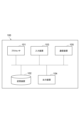
図1に示されるように、電力供給システム1は、電力供給家2に電力を供給するシステムである。電力供給家2は、電力を消費する設備群の集合である。電力供給家2の例としては、一般家庭をはじめとする低圧需要家を含んでもよい。電力供給システム1は、変動性再生可能エネルギー発電装置10、発電装置20、蓄エネルギー装置30、及び電力供給制御装置40を備えている。
As shown in FIG. 1, the
変動性再生可能エネルギー発電装置10は、変動性再生可能エネルギー(Variable Renewable Energy)を用いて発電を行う発電装置である。以下、変動性再生可能エネルギー発電装置10を、VRE発電装置10と称する。VRE発電装置10は、例えば、太陽光発電装置であってもよく、風力発電装置であってもよく、太陽光及び風力以外の変動性再生可能エネルギーを用いた発電装置であってもよい。
The variable renewable energy
ここで、VRE発電装置10の出力電力は急変することがある。例えば、VRE発電装置10が太陽光発電装置である場合、雲によって太陽光が遮られること等によって、VRE発電装置10の出力電力が急に低下することがある。また、例えば、VRE発電装置10が風力発電装置である場合、風が止むこと等によって、VRE発電装置10の出力電力が急に低下することがある。電力供給システム1は、VRE発電装置10の出力電力が低下した場合に、出力電力の低下分を発電装置20及び蓄エネルギー装置30の少なくともいずれかを用いて補う。すなわち、発電装置20及び蓄エネルギー装置30は、VRE発電装置10の出力電力の低下分を補うための装置である。
Here, the output power of the VRE
発電装置20は、変動性再生可能エネルギーとは異なるエネルギー源を用いて発電を行う。発電装置20の例としては、ディーゼル発電装置、ガスエンジン発電装置、燃料電池等が挙げられる。
The
蓄エネルギー装置30は、エネルギーを蓄え、電力を出力する装置である。蓄エネルギー装置30は、発電装置20に比べて、電力を出力するまでの応答速度が速い。蓄エネルギー装置30の例としては、蓄電池、フライホイール蓄電装置、コンデンサ等が挙げられる。
The
電力供給制御装置40は、VRE発電装置10、発電装置20、及び蓄エネルギー装置30から電力供給家2への電力の供給を制御する装置である。まず、電力供給制御装置40のハードウェア構成について説明する。図2に示されるように、電力供給制御装置40は、1又は複数のコンピュータ100を含む。コンピュータ100は、プロセッサ101と、記憶装置102と、入力装置103と、出力装置104と、通信装置105と、を含む。電力供給制御装置40は、これらのハードウェアと、プログラム等のソフトウェアと、により構成された1又は複数のコンピュータ100によって構成される。つまり、電力供給制御装置40は、少なくとも1つのプロセッサ101を備えている。
The power
電力供給制御装置40が複数のコンピュータ100によって構成される場合には、これらのコンピュータ100はローカルで接続されてもよいし、インターネット又はイントラネット等の通信ネットワークを介して接続されてもよい。この接続によって、論理的に1つの電力供給制御装置40が構築される。
When the power
プロセッサ101は、オペレーティングシステム及びアプリケーション・プログラム等を実行する。プロセッサ101の例としては、CPU(Central Processing Unit)が挙げられる。記憶装置102は、ROM(Read Only Memory)及びRAM(Random Access Memory)によって構成される主記憶装置と、ハードディスク及びフラッシュメモリ等によって構成される補助記憶装置と、を含む。入力装置103は、キーボード、マウス、タッチパネル、及び音声入力用マイク等によって構成される。出力装置104は、ディスプレイ及びプリンタ等によって構成される。通信装置105は、ネットワークカード又は無線通信モジュールによって構成される。
The
記憶装置102は、コンピュータ100を電力供給制御装置40として機能させるためのプログラムと、処理に必要なデータと、を格納している。電力供給制御装置40の図1に示される各機能部(気象予測部41、低下予測部42、電力制御部43)は、プロセッサ101等のハードウェアにプログラムを読み込ませることにより、プロセッサ101の制御のもとで各ハードウェアを動作させるとともに、記憶装置102におけるデータの読み出し及び書き込みを行うことで実現される。
The
プログラムは、例えば、CD-ROM、DVD-ROM、及び半導体メモリ等の有形の記録媒体に記録された上で提供されてもよい。プログラムは、データ信号として通信ネットワークを介して提供されてもよい。 The program may be provided in a form recorded on a tangible recording medium such as a CD-ROM, DVD-ROM, or semiconductor memory. The program may be provided as a data signal via a communications network.
次に、電力供給制御装置40の機能的構成について説明する。図1に示されるように、電力供給制御装置40は、機能的には、気象予測部41、低下予測部42、及び電力制御部43を備えている。
Next, the functional configuration of the power
気象予測部41は、VRE発電装置10の設置位置における気象状況を予測する。本実施形態において、気象予測部41は、VRE発電装置10の設置位置の周囲に設定された観測地点における観測地点気象状況を取得し、取得した観測地点気象状況に基づいて、VRE発電装置10の設置位置における気象状況を予測する。なお、気象予測部41は、観測地点における観測地点気象状況を、周知の有線通信又は無線通信によって外部装置から取得することができる。
The
例えば、気象予測部41は、観測地点からVRE発電装置10までの距離と、VRE発電装置10から見たときの観測地点の方向(方角)と、観測地点における観測地点気象状況と、に基づいて、VRE発電装置10の設置位置における気象状況を予測することができる。例えば、気象予測部41は、観測地点において観測された大きな影を作る雲が、VRE発電装置10の設置位置に到達するか否か及び到達するタイミングを、観測地点における風速及び風向等に基づいて予測することができる。
For example, the
ここでは、気象予測部41は、取得した観測地点気象状況に基づいて、現在から予め定められた気象予測時間が経過するまでの気象予測期間内における気象状況(気象状況の変動)を予測する。すなわち、気象予測部41は、現在から気象予測時間先までの気象状況を予測する。気象予測時間は、発電装置20が発電停止状態から電力供給可能状態となるまでに要する始動時間に予め定められた余裕時間を加えた時間に基づいて定められている。例えば、気象予測時間は、一例として、数分から数時間の時間が設定されていてもよい。
Here, the
また、気象予測部41は、2以上の観測地点における観測地点気象状況をそれぞれ取得し、取得した2以上の観測地点気象状況に基づいてVRE発電装置10の設置位置における気象状況を予測するとよい。気象予測部41は、2以上の観測地点気象状況を用いることにより、VRE発電装置10の設置位置における気象状況をより精度よく予測できる。
In addition, the
ここで、図3に示されるように、VRE発電装置10の設置位置Xの周囲に1以上の観測地点Pが予め設定されている。観測地点Pは、VRE発電装置10の設置位置Xから、例えば、予め定められた距離A[km]程度離れた位置に設定されている。この距離A[km]としては、一例として、数kmから数十kmが設定されていてもよい。観測地点Pは、設置位置Xの周囲にできるだけ均等に設定されているとよい。なお、図3に示される観測地点Pの数及び観測地点Pの設置位置は一例であり、観測地点Pの数及び設置位置は図3に示される例に限定されない。
Here, as shown in FIG. 3, one or more observation points P are set in advance around the installation position X of the VRE
観測地点Pは、当該観測地点Pにおける気象状況(観測地点気象状況)を観測する観測機器が設置されている地点であってもよい。この観測機器の例としては、日射量計、風速計、風向計、観測地点Pの上空の雲の動き等を撮像するためのカメラ、湿度計、気圧計、温度計等であってもよい。この場合、気象予測部41は、観測機器で観測された観測結果を、観測地点Pにおける観測地点気象状況として取得する。また、観測地点Pは、例えば家庭用の太陽光発電装置が設置されている地点であってもよい。この場合、気象予測部41は、日射量に対応する情報として、観測地点Pに設置された太陽光発電装置の発電量を当該観測地点Pにおける観測地点気象状況として取得する。なお、気象予測部41は、各地の気象情報を収集する気象情報収集センター等から、観測地点Pにおける観測地点気象状況を取得してもよい。
The observation point P may be a point where an observation device is installed to observe the weather conditions at the observation point P (observation point weather conditions). Examples of the observation device may be a solar radiation meter, anemometer, wind vane, a camera for capturing images of cloud movement above the observation point P, a hygrometer, a barometer, a thermometer, etc. In this case, the
気象予測部41は、予測するVRE発電装置10の設置位置における気象状況の種類として、VRE発電装置10の発電量に影響を与える気象状況を予測する。
The
まず、一例として、VRE発電装置10が太陽光発電装置である場合について説明する。この場合、気象予測部41は、気象状況として、VRE発電装置10の設置位置Xにおける日射量(日射量の変動)を予測する。ここでは、気象予測部41は、例えば、観測地点Pに設置された日射量計で計測された日射量、風速計で計測された風速、風向計で計測された風向、カメラによって撮像されたカメラ画像、湿度計で計測された湿度、気圧計で計測された気圧、温度計で計測された気温、及び、観測地点Pに設置された太陽光発電装置の発電量の少なくともいずれかに基づいて、周知の方法によって設置位置Xにおける日射量を予測することができる。例えば、気象予測部41は、カメラ画像に基づいて雲の動きを予測し、設置位置Xにおける日射量を予測することができる。例えば、気象予測部41は、湿度の変化、気圧の変化、及び気温の変化の少なくともいずれかを用いる場合、これらの変化に基づいて降雨状況を予測し、設置位置Xにおける日射量を予測することができる。
First, as an example, a case where the VRE
次に、一例として、VRE発電装置10が風力発電装置である場合について説明する。この場合、気象予測部41は、気象状況として、VRE発電装置10の設置位置Xにおける風量(風量の変動)を予測する。ここでは、気象予測部41は、例えば、風速計で計測された風速、風向計で計測された風向、気圧計で計測された気圧、及び、温度計で計測された気温の少なくともいずれかに基づいて、周知の方法によって設置位置Xにおける風量を予測することができる。例えば、気象予測部41は、気圧の変化、及び温度の変化の少なくともいずれかを用いる場合、これらの変化に基づいて風の流れを予測し、設置位置Xにおける風量を予測することができる。
Next, as an example, a case where the VRE
図1に示される低下予測部42は、気象予測部41で予測された気象状況に基づいて、VRE発電装置10の出力電力が低下する低下タイミングを予測する。具体的には、低下予測部42は、気象予測部41で予測された気象予測期間分の気象状況に基づいて、気象予測期間内にVRE発電装置10の出力電力が低下するか否かを予測し、出力電力が低下すると予測されたタイミングを低下タイミングとして用いる。ここでは、低下予測部42は、出力電力が急に低下するタイミングを低下タイミングとして用いる。具体的には、低下予測部42は、VRE発電装置10の出力電力が、例えば、予め定められた基準時間以内に予め定められた閾値以上低下すると予測されるタイミングを、低下タイミングとして用いる。このように、低下予測部42は、現在から気象予測時間が経過するまでの気象予測期間内にVRE発電装置10の出力電力が急に低下する低下タイミングを予測する。
The
なお、低下予測部42は、出力電力が低下するタイミングを予測できればよく、予め定められた閾値以上低下した後の出力電力の値については予測する必要がない。従って、低下予測部42は、低下タイミングをより精度よく予測できる。
The
電力制御部43は、電力供給システム1から電力供給家2への電力の供給を制御する。また、電力制御部43は、VRE発電装置10の出力電力の低下分を補うように発電装置20及び蓄エネルギー装置30の出力電力を制御する。本実施形態において電力制御部43は、低下予測部42で予測された低下タイミングに発電装置20が電力供給可能状態となるように発電装置20を制御する。そして、電力制御部43は、VRE発電装置10の出力電力が低下した場合には、VRE発電装置10の出力電力の低下分を補うように発電装置20及び蓄エネルギー装置30の少なくともいずれかの出力電力を制御する。
The
ここで、「VRE発電装置10の出力電力の低下分を補う」こととは、VRE発電装置10の出力電力が0となり、電力供給家2に供給すべき電力のすべてを発電装置20及び蓄エネルギー装置30の少なくともいずれかによって賄うことを含む。また、「VRE発電装置10の出力電力の低下分を補う」こととは、VRE発電装置10の出力電力が低下し、低下分を発電装置20及び蓄エネルギー装置30の少なくともいずれかによって賄うことを含む。すなわち、この場合とは、電力供給家2に供給すべき電力を、VRE発電装置10と、発電装置20及び蓄エネルギー装置30の少なくともいずれかと、によって賄うことである。
Here, "compensating for the decrease in the output power of the VRE
なお、発電装置20が電力供給可能状態であることとは、発電装置20が発電を開始し、予め定められた規定電力を出力可能な状態である。また、予測された低下タイミングに発電装置20が電力供給可能状態となることとは、低下タイミングちょうどに発電装置20が電力供給可能状態となることに加え、低下タイミングよりも前に発電装置20が電力供給可能状態となり、低下タイミングの時点で既に電力供給可能状態となっていることも含む。
The
以下、電力制御部43が行う制御の詳細な例について、場面(1)と、場面(2)の2つの場面に分けて説明する。場面(1)は、発電装置20が電力供給可能状態となる前にVRE発電装置10の出力電力が低下した場合である。すなわち、場面(1)とは、低下予測部42によって予測された電力の低下タイミングよりも早くVRE発電装置10の出力電力が低下する場合である。場面(2)は、発電装置20が電力供給可能状態となった後にVRE発電装置10の出力電力が低下した場合である。すなわち、場面(2)とは、低下予測部42によって予測された電力の低下タイミング以降にVRE発電装置10の出力電力が低下する場合である。
Below, detailed examples of the control performed by the
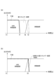
まず、場面(1)の場合に行われる制御について、図4(a)を用いて説明する。ここでは、低下予測部42が、図4(a)に示される時刻t2にVRE発電装置10の出力電力が低下すると予測していたとする。すなわち、低下予測部42が、出力電力が低下する低下タイミングとして、時刻t2を予測していた場合である。また、図4(a)に示される例では、時刻t2よりも前の時刻t1において、VRE発電装置10の出力電力が低下する。なお、図4(a)のグラフにおいて、太線は実際のVRE発電装置10の出力電力を示し、二点鎖線は予測されたVRE発電装置10の出力電力を示し、破線は蓄エネルギー装置30の出力電力を示し、太線よりも細い実線は発電装置20の出力電力を示している。以下で説明する図4(b)についても同様とする。
First, the control performed in the case of scene (1) will be described with reference to FIG. 4(a). Here, it is assumed that the
図4(a)に示されるように、電力制御部43は、時刻t1においてVRE発電装置10の出力が低下した場合、蓄エネルギー装置30の出力電力によってVRE発電装置10の出力電力の低下分を補う。すなわち、電力制御部43は、発電装置20が電力供給可能状態となる前は蓄エネルギー装置30によってVRE発電装置10の出力電力の低下分を補う。そして、電力制御部43は、発電装置20が電力供給可能状態となった時刻t2以降は、発電装置20の出力電力によってVRE発電装置10の出力電力の低下分を補う。この場合、電力制御部43は、時刻t2以降は蓄エネルギー装置30による電力供給を停止させる。
As shown in FIG. 4(a), when the output of the VRE
なお、電力制御部43は、発電装置20が始動して電力の出力を開始した時刻ta以降、発電装置20が予め定められた規定電力を出力可能な状態となるまでの間(時刻taから時刻t2までの間)において、発電装置20の出力電力と蓄エネルギー装置30の出力電力とを合わせた電力によってVRE発電装置10の出力電力の低下分を補ってもよい。また、電力制御部43は、VRE発電装置10の出力電力の低下分を発電装置20の出力電力によって補う際に、例えば発電装置20の始動直後など発電装置20の出力電力に変動が生じる場合、発電装置20の出力電力の変動を蓄エネルギー装置30の出力電力によって補ってもよい。
The
次に、場面(2)の場合に行われる制御について、図4(b)を用いて説明する。ここでは、低下予測部42が、図4(b)に示される時刻t3にVRE発電装置10の出力電力が低下すると予測していたとする。すなわち、低下予測部42が、出力電力が低下する低下タイミングとして、時刻t3を予測していた場合である。また、図4(b)に示される例では、時刻t3において、VRE発電装置10の出力電力が低下する。
Next, the control performed in the case of scene (2) will be described with reference to FIG. 4(b). Here, it is assumed that the
図4(b)に示されるように、電力制御部43は、低下予測部42によって出力電力が低下すると予測された時刻t3に、電力供給可能状態となるように発電装置20を予め始動させる。そして、時刻t3においてVRE発電装置10の出力が低下した場合、電力制御部43は、電力供給可能状態となっている発電装置20の出力電力によって、VRE発電装置10の出力電力の低下分を補う。この場合、電力制御部43は、蓄エネルギー装置30から電力を出力させない。また、電力制御部43は、発電装置20が電力の出力を開始した後、VRE発電装置10と発電装置20との合計の出力電力のうち余剰となる電力によって蓄エネルギー装置30を充電する(余剰分を蓄エネルギー装置30で吸収させる)ことができる。
As shown in FIG. 4(b), the
なお、場面(1)及び(2)の場合において、電力制御部43は、VRE発電装置10の出力電力が復帰した場合、発電装置20及び蓄エネルギー装置30による電力供給を停止又は低下させ、VRE発電装置10を主として電力供給家2へ電力を供給する。
In addition, in the cases of scenarios (1) and (2), when the output power of the VRE
また、電力制御部43は、低下予測部42においてVRE発電装置10の出力電力が低下すると予測されたにも関わらずVRE発電装置10の出力電力が低下しない場合(すなわち予測が外れた場合)、VRE発電装置10から電力供給家2への電力供給を維持する。
In addition, if the output power of the VRE
ここで、電力制御部43は、発電装置20を電力供給可能状態となるように始動させる場合、蓄エネルギー装置30の残りの電力量に応じて、発電装置20を電力供給可能状態とするタイミングを変更してもよい。具体的には、電力制御部43は、発電装置20を電力供給可能状態となるように制御する場合、蓄エネルギー装置30の残りの電力量が少ないときには、蓄エネルギー装置30の残りの電力量が多いときに比べて発電装置20が早く電力供給可能状態となるように制御してもよい。
Here, when starting the
また、電力制御部43は、VRE発電装置10によって電力の供給を行っている場合、VRE発電装置10の電力によって蓄エネルギー装置30の充電を行ってもよい。
In addition, when power is being supplied by the VRE
次に、電力供給制御装置40において実行される電力供給制御方法の一例について、図5のフローチャートを用いて説明する。ここでは、予測された気象状況に基づいて電力の供給を行う制御を中心に説明する。図5に示されるフローチャートの処理は、VRE発電装置10による電力供給の開始とともに開始される。また、処理がエンドに至った場合、再びスタートから処理が行われる。
Next, an example of a power supply control method executed by the power
図5に示されるように、気象予測部41は、VRE発電装置10の設置位置における気象状況を予測する(S101:気象予測ステップ)。低下予測部42は、気象予測部41で予測された気象状況に基づいて、VRE発電装置10の出力電力が低下する低下タイミングを予測する(S102:低下予測ステップ)。電力制御部43は、低下予測部42において出力電力が低下する低下タイミングが予測されたか否かを判定する(S103)。電力が低下する低下タイミングが予測されていない場合(S103:NO)、気象予測部41は、再びS101の処理を行う。
As shown in FIG. 5, the
一方、電力が低下する低下タイミングが予測されている場合(S103:YES)、電力制御部43は、VRE発電装置10の出力電力の低下に応じて、VRE発電装置10の出力電力の低下分を補うように発電装置20及び蓄エネルギー装置30の出力電力を制御する(S104:電力制御ステップ)。ここでは、電力制御部43は、予測された低下タイミングに発電装置20が電力供給可能状態となるように発電装置20を制御する。そして、電力制御部43は、VRE発電装置10の低下分を補うように発電装置20及び蓄エネルギー装置30の少なくともいずれかの出力電力を制御する。
On the other hand, if the timing of the power decrease is predicted (S103: YES), the
次に、図5のS104において行われる処理の詳細について、図6のフローチャートを用いて説明する。なお、電力制御部43は、図6に示されるフローチャートとは別に、低下予測部42で予測された低下タイミングに発電装置20が電力供給可能状態となるように発電装置20の制御(始動の制御)を行っている。
Next, the details of the process performed in S104 in FIG. 5 will be described with reference to the flowchart in FIG. 6. Note that the
低下予測部42によって低下タイミングが予測されると、電力制御部43は、図6に示されるように、VRE発電装置10の出力電力が低下したか否かを判定する(S201)。VRE発電装置10の出力電力が低下していない場合(S201:NO)、電力制御部43は、VRE発電装置10から電力供給家2への電力供給を維持し、再びS201の処理を行う。
When the timing of the decrease is predicted by the
一方、VRE発電装置10の出力電力が低下した場合(S201:YES)、電力制御部43は、発電装置20が電力供給可能状態となっているか否かを判定する(S202)。発電装置20が電力供給可能状態である場合(S202:YES)、電力制御部43は、発電装置20の出力電力によって、VRE発電装置10の出力電力の低下分を補う(S203)。その後、VRE発電装置10の出力電力が復帰した場合、電力制御部43は、VRE発電装置10から電力供給家2へ電力を供給する。
On the other hand, if the output power of the VRE
一方、発電装置20が電力供給可能状態ではない場合(S202:NO)、電力制御部43は、蓄エネルギー装置30の出力電力によって、VRE発電装置10の出力電力の低下分を補う(S204)。そして、電力制御部43は、発電装置20が電力供給可能状態となっているか否かを判定する(S205)。発電装置20が電力供給可能状態ではない場合(S205:NO)、電力制御部43は、S204の処理を行う。すなわち、電力制御部43は、発電装置20が電力供給可能状態となるまで、蓄エネルギー装置30によって電力供給を行う。
On the other hand, if the
発電装置20が電力供給可能状態となった場合(S205:YES)、電力制御部43は、発電装置20の出力電力によってVRE発電装置10の出力電力の低下分を補い、蓄エネルギー装置30による電力供給を停止させる(S206)。その後、VRE発電装置10の出力電力が復帰した場合、電力制御部43は、VRE発電装置10から電力供給家2へ電力を供給する。
[作用及び効果]
When the
[Action and Effects]
以上のように、電力供給制御装置40では、VRE発電装置10の出力電力が低下すると予測された低下タイミングに発電装置20が電力供給可能状態となっている。このため、電力供給制御装置40は、VRE発電装置10の出力電力の低下分を発電装置20の出力電力によっても補うことができる。従って、電力供給制御装置40は、蓄エネルギー装置30の小容量化を図りつつ、発電装置20及び蓄エネルギー装置30の少なくともいずれかによってVRE発電装置10の出力電力の低下分を補うことができる。
As described above, in the power
電力制御部43は、発電装置20が電力供給可能状態となる前にVRE発電装置10の出力電力が低下した場合(上述した場面(1)の場合)、発電装置20が電力供給可能状態となる前は蓄エネルギー装置30によってVRE発電装置10の出力電力の低下分を補い、発電装置20が電力供給可能状態となった後は発電装置20によってVRE発電装置10の出力電力の低下分を補う。この場合、電力供給制御装置40は、予測された低下タイミングよりも早くVRE発電装置10の出力電力が低下し、発電装置20が電力供給可能状態となる前の状態であっても、蓄エネルギー装置30によって出力電力の低下分を補うことができる。そして、電力供給制御装置40は、発電装置20が電力供給可能状態となった後は発電装置20によってVRE発電装置10の出力電力の低下分を補うことができる。つまり、蓄エネルギー装置30は、発電装置20が電力供給可能状態となるまでの間だけ使用できればよい。従って、電力供給制御装置40は、蓄エネルギー装置の小容量化を図ることができる。
When the output power of the VRE
電力制御部43は、発電装置20が電力供給可能状態となった後にVRE発電装置10の出力電力が低下した場合(上述した場面(2)の場合)、発電装置20によってVRE発電装置10の出力電力の低下分を補う。この場合、電力供給制御装置40は、発電装置20の出力電力によって、VRE発電装置10の出力電力の低下分を補うことができる。
When the output power of the VRE
気象予測部41は、現在から予め定められた気象予測時間が経過するまでの気象予測期間内における気象状況を予測する。気象予測時間は、発電装置20が発電停止状態から電力供給可能状態となるまでに要する始動時間に予め定められた余裕時間を加えた時間に基づいて定められている。この場合、気象予測部41は、発電装置20の始動時間に基づいて定められた気象予測時間先までの気象状況を予測すればよい。つまり、気象予測部41は、発電装置20が始動に要する時間だけ気象状況を予測できればよく、長時間先(気象予測時間より先)の気象状況を予測する必要がない。従って、気象予測部41は、気象状況を予測する期間が限定されていることにより、気象状況をより精度よく予測できる。
The
気象予測部41は、2以上の観測地点Pにおける観測地点気象状況に基づいて、VRE発電装置10の設置位置における気象状況を予測する。この場合、気象予測部41は、VRE発電装置10の設置位置における気象状況をより精度よく予測できる。
The
電力制御部43は、発電装置20を電力供給可能状態となるように制御する場合、蓄エネルギー装置30の残りの電力量が少ないときには、蓄エネルギー装置30の残りの電力量が多いときに比べて発電装置20が早く電力供給可能状態となるように制御してもよい。この場合、電力供給制御装置40は、VRE発電装置10の出力電力が予測された低下タイミングよりも早く低下し、出力電力の低下分を蓄エネルギー装置30によって補っている場合において、蓄エネルギー装置30の残りの電力が無くなる前に発電装置20によって電力供給を行うことができる可能性を高めることができる。
When controlling the
また、電力供給制御装置40において実行される電力供給制御方法、及び電力供給制御装置40を含む電力供給システム1についても、上述した電力供給制御装置40と同様の効果を奏することができる。
Furthermore, the power supply control method executed in the power
このように、本開示は、例えば、国連が主導する持続可能な開発目標(Sustainable Development Goals:SDGs)の目標7「すべての人々の、安価かつ信頼できる持続可能な近代的エネルギーへのアクセスを確保する」に貢献することができる。 In this way, this disclosure can contribute, for example, to Goal 7 of the United Nations-led Sustainable Development Goals (SDGs), "Ensure access to affordable, reliable, sustainable and modern energy for all."
以上、本発明の実施形態について説明したが、本発明は、上記実施形態に限定されるものではない。例えば、電力供給制御装置40は、VRE発電装置10の出力電力が低下する低下タイミングが予測された場合、低下タイミングに負荷(電力消費量)を減らすように又は事前に負荷を減らすように電力供給家2に対して指示をしてもよい。
Although the embodiment of the present invention has been described above, the present invention is not limited to the above embodiment. For example, when the power
1 電力供給システム
10 VRE発電装置(変動性再生可能エネルギー発電装置)
20 発電装置
30 蓄エネルギー装置
40 電力供給制御装置
41 気象予測部
42 低下予測部
43 電力制御部
P 観測地点
X VRE発電装置の設置位置
1
20
Claims (7)
前記変動性再生可能エネルギー発電装置の設置位置における気象状況を予測する気象予測部と、
前記気象予測部で予測された前記気象状況に基づいて、前記変動性再生可能エネルギー発電装置の出力電力が低下する低下タイミングを予測する低下予測部と、
前記変動性再生可能エネルギー発電装置の出力電力の低下分を補うように前記発電装置及び前記蓄エネルギー装置の出力電力を制御する電力制御部と、
を備え、
前記電力制御部は、
前記低下予測部で前記変動性再生可能エネルギー発電装置の出力電力が低下すると予測された後、予測された前記低下タイミングに前記発電装置が電力供給可能状態となるように所定の始動タイミングで前記発電装置を始動させ、
前記変動性再生可能エネルギー発電装置の出力電力の低下分を補うように前記発電装置及び前記蓄エネルギー装置の少なくともいずれかの出力電力を制御し、
前記発電装置を前記電力供給可能状態となるように制御する場合、前記蓄エネルギー装置の残りの電力量が少ないときには、前記蓄エネルギー装置の残りの電力量が多いときに比べて早く前記電力供給可能状態となるように前記発電装置を制御する、電力供給制御装置。 A power supply control device used in a power supply system including a variable renewable energy power generation device, and a power generation device and an energy storage device for compensating for a decrease in output power of the variable renewable energy power generation device,
A weather forecasting unit that predicts weather conditions at an installation location of the variable renewable energy power generation device;
A decrease prediction unit that predicts a decrease timing of the output power of the variable renewable energy power generation device based on the weather condition predicted by the weather prediction unit;
A power control unit that controls the output power of the power generation device and the energy storage device so as to compensate for a decrease in the output power of the variable renewable energy power generation device;
Equipped with
The power control unit is
After the decrease prediction unit predicts that the output power of the variable renewable energy power generation device will decrease, the power generation device is started at a predetermined start timing so that the power generation device is in a power supply capable state at the predicted decrease timing;
Controlling the output power of at least one of the power generation device and the energy storage device so as to compensate for a decrease in the output power of the variable renewable energy power generation device ;
A power supply control device that, when controlling the power generation device to reach the power supply possible state, controls the power generation device so that the power supply possible state is reached more quickly when the remaining amount of power of the energy storage device is small compared to when the remaining amount of power of the energy storage device is large .
前記低下予測部は、前記気象予測部で予測された前記気象状況に基づいて、前記気象予測期間内に前記変動性再生可能エネルギー発電装置の出力電力が低下するか否かを予測し、前記出力電力が低下すると予測されたタイミングを前記低下タイミングとして用い、
前記気象予測時間は、前記発電装置が発電停止状態から前記電力供給可能状態となるまでに要する始動時間に予め定められた余裕時間を加えた時間に基づいて定められている、請求項1~3のいずれか一項に記載の電力供給制御装置。 The weather forecasting unit forecasts the weather conditions within a weather forecast period from the present until a predetermined weather forecast time has elapsed,
The decrease prediction unit predicts whether or not the output power of the variable renewable energy power generation device will decrease within the weather prediction period based on the weather conditions predicted by the weather prediction unit, and uses the timing at which the output power is predicted to decrease as the decrease timing,
The power supply control device according to any one of claims 1 to 3, wherein the weather forecast time is determined based on a time that is a predetermined margin time added to a start-up time required for the power generation device to go from a power generation stopped state to the power supply possible state.
前記変動性再生可能エネルギー発電装置の設置位置における気象状況を予測する気象予測ステップと、
前記気象予測ステップにおいて予測された前記気象状況に基づいて、前記変動性再生可能エネルギー発電装置の出力電力が低下する低下タイミングを予測する低下予測ステップと、
前記変動性再生可能エネルギー発電装置の出力電力の低下分を補うように前記発電装置及び前記蓄エネルギー装置の出力電力を制御する電力制御ステップと、
を含み、
前記電力制御ステップでは、
前記低下予測ステップで前記変動性再生可能エネルギー発電装置の出力電力が低下すると予測された後、予測された前記低下タイミングに前記発電装置が電力供給可能状態となるように所定の始動タイミングで前記発電装置を始動させ、
前記変動性再生可能エネルギー発電装置の出力電力の低下分を補うように前記発電装置及び前記蓄エネルギー装置の少なくともいずれかの出力電力を制御し、
前記発電装置を前記電力供給可能状態となるように制御する場合、前記蓄エネルギー装置の残りの電力量が少ないときには、前記蓄エネルギー装置の残りの電力量が多いときに比べて早く前記電力供給可能状態となるように前記発電装置を制御する、電力供給制御方法。 A power supply control method executed in a power supply control device used in a power supply system including a variable renewable energy power generation device, and a power generation device and an energy storage device for compensating for a decrease in output power of the variable renewable energy power generation device,
A weather forecasting step of predicting weather conditions at an installation location of the variable renewable energy power generation device;
A decrease prediction step of predicting a decrease timing of the output power of the variable renewable energy power generation device based on the weather condition predicted in the weather prediction step;
A power control step of controlling the output power of the power generation device and the energy storage device so as to compensate for a decrease in the output power of the variable renewable energy power generation device;
Including,
In the power control step,
After the output power of the variable renewable energy power generation device is predicted to decrease in the decrease prediction step, the power generation device is started at a predetermined start timing so that the power generation device is in a power supply capable state at the predicted decrease timing;
Controlling the output power of at least one of the power generation device and the energy storage device so as to compensate for a decrease in the output power of the variable renewable energy power generation device ;
A power supply control method, in which, when controlling the power generation device to reach the power supply possible state, when the remaining amount of power of the energy storage device is small, the power generation device is controlled to reach the power supply possible state more quickly than when the remaining amount of power of the energy storage device is large .
前記電力供給制御装置は、
前記変動性再生可能エネルギー発電装置の設置位置における気象状況を予測する気象予測部と、
前記気象予測部で予測された前記気象状況に基づいて、前記変動性再生可能エネルギー発電装置の出力電力が低下する低下タイミングを予測する低下予測部と、
前記変動性再生可能エネルギー発電装置の出力電力の低下分を補うように前記発電装置及び前記蓄エネルギー装置の出力電力を制御する電力制御部と、
を備え、
前記電力制御部は、
前記低下予測部で前記変動性再生可能エネルギー発電装置の出力電力が低下すると予測された後、予測された前記低下タイミングに前記発電装置が電力供給可能状態となるように所定の始動タイミングで前記発電装置を始動させ、
前記変動性再生可能エネルギー発電装置の出力電力の低下分を補うように前記発電装置及び前記蓄エネルギー装置の少なくともいずれかの出力電力を制御し、
前記発電装置を前記電力供給可能状態となるように制御する場合、前記蓄エネルギー装置の残りの電力量が少ないときには、前記蓄エネルギー装置の残りの電力量が多いときに比べて早く前記電力供給可能状態となるように前記発電装置を制御する、電力供給システム。 A power supply system including a variable renewable energy power generation device, a power generation device and an energy storage device for compensating for a decrease in the output power of the variable renewable energy power generation device, and a power supply control device for controlling the output power of the power generation device and the energy storage device,
The power supply control device includes:
A weather forecasting unit that predicts weather conditions at an installation location of the variable renewable energy power generation device;
A decrease prediction unit that predicts a decrease timing of the output power of the variable renewable energy power generation device based on the weather condition predicted by the weather prediction unit;
A power control unit that controls the output power of the power generation device and the energy storage device so as to compensate for a decrease in the output power of the variable renewable energy power generation device;
Equipped with
The power control unit is
After the decrease prediction unit predicts that the output power of the variable renewable energy power generation device will decrease, the power generation device is started at a predetermined start timing so that the power generation device is in a power supply capable state at the predicted decrease timing;
Controlling the output power of at least one of the power generation device and the energy storage device so as to compensate for a decrease in the output power of the variable renewable energy power generation device ;
When controlling the power generation device to reach the power supply possible state, when the remaining amount of power of the energy storage device is small, the power generation device is controlled so as to reach the power supply possible state more quickly than when the remaining amount of power of the energy storage device is large .
Priority Applications (1)
| Application Number | Priority Date | Filing Date | Title |
|---|---|---|---|
| JP2020207760A JP7574635B2 (en) | 2020-12-15 | 2020-12-15 | Power supply control device, power supply control method, and power supply system |
Applications Claiming Priority (1)
| Application Number | Priority Date | Filing Date | Title |
|---|---|---|---|
| JP2020207760A JP7574635B2 (en) | 2020-12-15 | 2020-12-15 | Power supply control device, power supply control method, and power supply system |
Publications (2)
| Publication Number | Publication Date |
|---|---|
| JP2022094717A JP2022094717A (en) | 2022-06-27 |
| JP7574635B2 true JP7574635B2 (en) | 2024-10-29 |
Family
ID=82162703
Family Applications (1)
| Application Number | Title | Priority Date | Filing Date |
|---|---|---|---|
| JP2020207760A Active JP7574635B2 (en) | 2020-12-15 | 2020-12-15 | Power supply control device, power supply control method, and power supply system |
Country Status (1)
| Country | Link |
|---|---|
| JP (1) | JP7574635B2 (en) |
Citations (4)
| Publication number | Priority date | Publication date | Assignee | Title |
|---|---|---|---|---|
| JP2006050691A (en) | 2004-07-30 | 2006-02-16 | Canon Inc | Power generation device and control method thereof |
| JP2013179740A (en) | 2012-02-28 | 2013-09-09 | Sharp Corp | Compound type self-power generation system and control method therefor |
| JP2015138864A (en) | 2014-01-22 | 2015-07-30 | 株式会社日立製作所 | Output estimation method and apparatus of photovoltaic power generator and electric power system monitoring apparatus using the same |
| JP2016019404A (en) | 2014-07-10 | 2016-02-01 | 三菱電機株式会社 | Failure judgment device |
-
2020
- 2020-12-15 JP JP2020207760A patent/JP7574635B2/en active Active
Patent Citations (4)
| Publication number | Priority date | Publication date | Assignee | Title |
|---|---|---|---|---|
| JP2006050691A (en) | 2004-07-30 | 2006-02-16 | Canon Inc | Power generation device and control method thereof |
| JP2013179740A (en) | 2012-02-28 | 2013-09-09 | Sharp Corp | Compound type self-power generation system and control method therefor |
| JP2015138864A (en) | 2014-01-22 | 2015-07-30 | 株式会社日立製作所 | Output estimation method and apparatus of photovoltaic power generator and electric power system monitoring apparatus using the same |
| JP2016019404A (en) | 2014-07-10 | 2016-02-01 | 三菱電機株式会社 | Failure judgment device |
Also Published As
| Publication number | Publication date |
|---|---|
| JP2022094717A (en) | 2022-06-27 |
Similar Documents
| Publication | Publication Date | Title |
|---|---|---|
| Gabrielli et al. | Electrochemical conversion technologies for optimal design of decentralized multi-energy systems: Modeling framework and technology assessment | |
| CN114221353B (en) | Power grid control methods, devices, equipment, storage media and computer program products | |
| Kiaee et al. | Utilisation of alkaline electrolysers to improve power system frequency stability with a high penetration of wind power | |
| KR102240556B1 (en) | Methods and apparatuses for operating power generator combined with heterogeneous renewable energy | |
| Jia et al. | Control of the dual mode operation of generator/motor in SOFC/GT-based APU for extended dynamic capabilities | |
| Sun et al. | Improving the restorability of bulk power systems with the implementation of a WF-BESS system | |
| WO2014112454A1 (en) | Control apparatus, method, and program, and natural energy generation apparatus provided with control apparatus, method, and program | |
| CN112310956A (en) | energy management system | |
| US20220060026A1 (en) | Power management system, power management method, and power management program | |
| JP3609397B2 (en) | Power supply system, housing complex, and program | |
| CN111727539A (en) | Control device for power supply system, control method for power supply system, and power supply system | |
| JP2014169660A (en) | Wind power generation control device and wind power generation control method | |
| CN115313422A (en) | Operation control method of electricity-gas comprehensive energy system for actively supporting main network frequency | |
| JP7574635B2 (en) | Power supply control device, power supply control method, and power supply system | |
| CN117578525A (en) | Power energy storage backup method and related device | |
| KR20210088006A (en) | Hybrid power generation system with smooth power output | |
| JP2024034266A (en) | Energy management systems, energy management methods and programs | |
| JP7146938B2 (en) | Energy management systems, independent systems, and methods of operating independent systems | |
| JP2025107267A (en) | Power Generation System | |
| JP6507666B2 (en) | Power failure time period prediction device, power failure time period prediction method, program | |
| JP2016127622A (en) | Power demand forecasting system | |
| CN119398232A (en) | Two-stage robust optimization configuration method for integrated energy systems and related components | |
| JP7767989B2 (en) | Photovoltaic power generation prediction device, and control method and program for photovoltaic power generation prediction device | |
| JP2008043148A (en) | Power supply system, control method and program for power supply system | |
| CN117638927B (en) | Flexible operation control method, system and storage medium for grid-interactive microgrid system |
Legal Events
| Date | Code | Title | Description |
|---|---|---|---|
| A621 | Written request for application examination |
Free format text: JAPANESE INTERMEDIATE CODE: A621 Effective date: 20230810 |
|
| A977 | Report on retrieval |
Free format text: JAPANESE INTERMEDIATE CODE: A971007 Effective date: 20240411 |
|
| A131 | Notification of reasons for refusal |
Free format text: JAPANESE INTERMEDIATE CODE: A131 Effective date: 20240514 |
|
| A521 | Request for written amendment filed |
Free format text: JAPANESE INTERMEDIATE CODE: A523 Effective date: 20240712 |
|
| TRDD | Decision of grant or rejection written | ||
| A01 | Written decision to grant a patent or to grant a registration (utility model) |
Free format text: JAPANESE INTERMEDIATE CODE: A01 Effective date: 20240917 |
|
| A61 | First payment of annual fees (during grant procedure) |
Free format text: JAPANESE INTERMEDIATE CODE: A61 Effective date: 20240930 |
|
| R150 | Certificate of patent or registration of utility model |
Ref document number: 7574635 Country of ref document: JP Free format text: JAPANESE INTERMEDIATE CODE: R150 |