JP7574591B2 - Image forming device - Google Patents

Image forming device Download PDF

Info

Publication number
JP7574591B2
JP7574591B2 JP2020162191A JP2020162191A JP7574591B2 JP 7574591 B2 JP7574591 B2 JP 7574591B2 JP 2020162191 A JP2020162191 A JP 2020162191A JP 2020162191 A JP2020162191 A JP 2020162191A JP 7574591 B2 JP7574591 B2 JP 7574591B2
Authority
JP
Japan
Prior art keywords
facing surface
path
photoelectric sensor
paper
image forming
Prior art date
Legal status (The legal status is an assumption and is not a legal conclusion. Google has not performed a legal analysis and makes no representation as to the accuracy of the status listed.)
Active
Application number
JP2020162191A
Other languages
Japanese (ja)
Other versions
JP2022054917A (en
Inventor
宏典 醍醐
Current Assignee (The listed assignees may be inaccurate. Google has not performed a legal analysis and makes no representation or warranty as to the accuracy of the list.)
Kyocera Document Solutions Inc
Original Assignee
Kyocera Document Solutions Inc
Priority date (The priority date is an assumption and is not a legal conclusion. Google has not performed a legal analysis and makes no representation as to the accuracy of the date listed.)
Filing date
Publication date
Application filed by Kyocera Document Solutions Inc filed Critical Kyocera Document Solutions Inc
Priority to JP2020162191A priority Critical patent/JP7574591B2/en
Priority to US17/486,314 priority patent/US11660882B2/en
Publication of JP2022054917A publication Critical patent/JP2022054917A/en
Application granted granted Critical
Publication of JP7574591B2 publication Critical patent/JP7574591B2/en
Active legal-status Critical Current
Anticipated expiration legal-status Critical

Links

Images

Classifications

    • BPERFORMING OPERATIONS; TRANSPORTING
    • B41PRINTING; LINING MACHINES; TYPEWRITERS; STAMPS
    • B41JTYPEWRITERS; SELECTIVE PRINTING MECHANISMS, i.e. MECHANISMS PRINTING OTHERWISE THAN FROM A FORME; CORRECTION OF TYPOGRAPHICAL ERRORS
    • B41J11/00Devices or arrangements  of selective printing mechanisms, e.g. ink-jet printers or thermal printers, for supporting or handling copy material in sheet or web form
    • B41J11/006Means for preventing paper jams or for facilitating their removal
    • BPERFORMING OPERATIONS; TRANSPORTING
    • B41PRINTING; LINING MACHINES; TYPEWRITERS; STAMPS
    • B41JTYPEWRITERS; SELECTIVE PRINTING MECHANISMS, i.e. MECHANISMS PRINTING OTHERWISE THAN FROM A FORME; CORRECTION OF TYPOGRAPHICAL ERRORS
    • B41J11/00Devices or arrangements  of selective printing mechanisms, e.g. ink-jet printers or thermal printers, for supporting or handling copy material in sheet or web form
    • B41J11/0095Detecting means for copy material, e.g. for detecting or sensing presence of copy material or its leading or trailing end
    • BPERFORMING OPERATIONS; TRANSPORTING
    • B41PRINTING; LINING MACHINES; TYPEWRITERS; STAMPS
    • B41JTYPEWRITERS; SELECTIVE PRINTING MECHANISMS, i.e. MECHANISMS PRINTING OTHERWISE THAN FROM A FORME; CORRECTION OF TYPOGRAPHICAL ERRORS
    • B41J29/00Details of, or accessories for, typewriters or selective printing mechanisms not otherwise provided for
    • B41J29/17Cleaning arrangements
    • BPERFORMING OPERATIONS; TRANSPORTING
    • B41PRINTING; LINING MACHINES; TYPEWRITERS; STAMPS
    • B41JTYPEWRITERS; SELECTIVE PRINTING MECHANISMS, i.e. MECHANISMS PRINTING OTHERWISE THAN FROM A FORME; CORRECTION OF TYPOGRAPHICAL ERRORS
    • B41J11/00Devices or arrangements  of selective printing mechanisms, e.g. ink-jet printers or thermal printers, for supporting or handling copy material in sheet or web form
    • B41J11/009Detecting type of paper, e.g. by automatic reading of a code that is printed on a paper package or on a paper roll or by sensing the grade of translucency of the paper

Landscapes

  • Control Or Security For Electrophotography (AREA)
  • Controlling Sheets Or Webs (AREA)

Description

本発明は、用紙に画像を形成する画像形成装置に関する。 The present invention relates to an image forming device that forms an image on paper.

原稿が原稿紙通路を通過する間にターゲットガラスの下方に配置された読取り装置で原稿を読み取る装置が知られている(特許文献1)。この装置では、原稿の代わりにクリーニングシートが原稿紙通路を通過することで、ターゲットガラス(原稿紙通路)がクリーニングされていた。 There is a known device that reads an original document using a reading device disposed below a target glass while the original document passes through an original document path (Patent Document 1). In this device, a cleaning sheet passes through the original document path instead of the original document, thereby cleaning the target glass (original document path).

特開昭50-152739号公報Japanese Unexamined Patent Publication No. 50-152739

しかしながら、上記した技術では、ターゲットガラス(原稿紙通路)に対するクリーニングの時期を知ることはできなかった。したがって、上記した技術では、原稿の読取不良や原稿の搬送不良が発生した後でなければクリーニング作業を行うことができなかった。 However, with the above technology, it was not possible to know when to clean the target glass (document paper path). Therefore, with the above technology, cleaning work could only be performed after a document reading error or document transport error had occurred.

本発明は、清掃等のメンテナンスを行う時期を検出することができる画像形成装置を提供する。 The present invention provides an image forming device that can detect when it is time to perform maintenance such as cleaning.

本発明の画像形成装置は、対向面部および前記対向面部上の用紙を含む被検出物に向けて投光し、前記被検出物で反射した反射光を受光し、前記反射光の光量に応じた電気信号を出力する反射型の光電センサーと、前記光電センサーの出力に応じて前記対向面部上における前記用紙の有無を判定する制御部であって、前記光電センサーの出力の閾値として、前記対向面部上に前記用紙が存在しないと判定する第1の閾値と、前記対向面部上に前記用紙が存在すると判定する第2の閾値と、を記憶し、前記光電センサーの出力が前記第1の閾値と前記第2の閾値との間となる場合に前記対向面部に前記反射光の光量を増加させる汚染が生じていると判定する制御部と、を備えた。 The image forming apparatus of the present invention includes a reflective photoelectric sensor that projects light toward an object to be detected, including an opposing surface and paper on the opposing surface, receives the light reflected by the object to be detected, and outputs an electrical signal corresponding to the amount of the reflected light, and a control unit that determines the presence or absence of paper on the opposing surface based on the output of the photoelectric sensor, storing a first threshold value for determining that the paper is not present on the opposing surface and a second threshold value for determining that the paper is present on the opposing surface as threshold values for the output of the photoelectric sensor, and determining that contamination has occurred on the opposing surface that increases the amount of the reflected light when the output of the photoelectric sensor is between the first threshold value and the second threshold value.

この場合、情報を表示する表示部を更に備え、前記制御部は、前記対向面部に汚染が生じていると判定した場合に前記対向面部のメンテナンスが必要であることを示す情報を前記表示部に表示させてもよい。 In this case, the device may further include a display unit that displays information, and the control unit may cause the display unit to display information indicating that maintenance of the facing surface is required when it is determined that contamination has occurred on the facing surface.

この場合、前記対向面部を清掃する清掃部を更に備え、前記制御部は、前記対向面部に汚染が生じていると判定した場合に前記対向面部の清掃を前記清掃部に実行させてもよい。 In this case, the device may further include a cleaning unit that cleans the opposing surface, and the control unit may cause the cleaning unit to clean the opposing surface when it is determined that contamination has occurred on the opposing surface.

この場合、ハウジングに開閉可能に取り付けられ、前記対向面部または前記光電センサーが設けられたカバーを更に備え、前記制御部は、前記光電センサーの出力が前記第1の閾値を挟んで前記第2の閾値とは反対側で、且つ前記第1の閾値から所定範囲外となった場合に前記カバーが完全に閉じられていない半開き状態であると判定してもよい。 In this case, the housing may further include a cover that is openably and closably attached to the housing and has the opposing surface portion or the photoelectric sensor provided thereon, and the control unit may determine that the cover is not completely closed and is in a half-open state when the output of the photoelectric sensor is on the opposite side of the first threshold value from the second threshold value and outside a predetermined range from the first threshold value.

この場合、情報を表示する表示部を更に備え、前記制御部は、前記カバーが前記半開き状態であると判定した場合に前記カバーが完全に閉じられていないことを示す情報を前記表示部に表示させてもよい。 In this case, the device may further include a display unit that displays information, and when the control unit determines that the cover is in the half-open state, the control unit may cause the display unit to display information indicating that the cover is not completely closed.

本発明によれば、清掃等のメンテナンスを行う時期を検出することができる。 The present invention makes it possible to detect when maintenance such as cleaning should be performed.

本発明の一実施形態に係る画像形成装置の概要を示す断面図である。1 is a cross-sectional view showing an overview of an image forming apparatus according to an embodiment of the present invention. 本発明の一実施形態に係る画像形成装置の制御部等を示すブロック図である。2 is a block diagram showing a control unit and the like of the image forming apparatus according to one embodiment of the present invention; 本発明の一実施形態に係る画像形成装置の右側の一部を示す断面図である。2 is a cross-sectional view showing a part of the right side of the image forming apparatus according to the embodiment of the present invention. 本発明の一実施形態に係る画像形成装置の第1の搬送経路の下流側を拡大して示す断面図である。2 is an enlarged cross-sectional view showing a downstream side of a first transport path of an image forming apparatus according to an embodiment of the present invention; FIG. 本発明の一実施形態に係る画像形成装置の第1の搬送経路の下流側(用紙の搬送中)を拡大して示す断面図である。2 is an enlarged cross-sectional view showing the downstream side of a first transport path (while a sheet is being transported) of the image forming apparatus according to one embodiment of the present invention. FIG. 本発明の一実施形態に係る画像形成装置の光電センサーの出力を示すグラフである。5 is a graph showing an output of a photoelectric sensor of an image forming apparatus according to an embodiment of the present invention. 本発明の一実施形態に係る画像形成装置のジャム検出方法を示すフローチャートである。5 is a flowchart showing a method for detecting a jam in an image forming apparatus according to an embodiment of the present invention. 本発明の一実施形態の第1変形例に係る画像形成装置の制御部等を示すブロック図である。FIG. 13 is a block diagram showing a control unit and the like of an image forming apparatus according to a first modified example of an embodiment of the present invention. 本発明の一実施形態の第1変形例に係る画像形成装置のジャム検出方法を示すフローチャートである。10 is a flowchart showing a jam detection method for an image forming apparatus according to a first modified example of an embodiment of the present invention. 本発明の一実施形態の第2変形例に係る画像形成装置の制御部等を示すブロック図である。FIG. 11 is a block diagram showing a control unit and the like of an image forming apparatus according to a second modified example of the embodiment of the present invention. 本発明の一実施形態の第2変形例に係る画像形成装置の右側の一部であってカバーの半開き状態を説明する断面図である。13 is a cross-sectional view illustrating a part of the right side of an image forming apparatus according to a second modified example of the embodiment of the present invention, with the cover in a half-open state. FIG. 本発明の一実施形態の第2変形例に係る画像形成装置の第1の搬送経路の下流側であってカバーの半開き状態を説明する断面図である。FIG. 11 is a cross-sectional view illustrating a state where the cover is half-opened, on the downstream side of the first transport path, of an image forming apparatus according to a second modified example of the embodiment of the present invention. 本発明の一実施形態の第2変形例に係る画像形成装置の光電センサーの出力を示すグラフである。10 is a graph showing an output of a photoelectric sensor of an image forming apparatus according to a second modified example of the embodiment of the present invention. 本発明の一実施形態の第3変形例に係る画像形成装置の光電センサーの出力を示すグラフである。10 is a graph showing an output of a photoelectric sensor of an image forming apparatus according to a third modified example of an embodiment of the present invention.

以下、添付の図面を参照しつつ、本発明の好適な実施形態について説明する。なお、図面に示すL、R、U、Dは左、右、上、下を示し、これらの図面では紙面手の手前を「前」としている。また、本明細書では方向や位置を示す用語を用いるが、それらの用語は説明の便宜のために用いるものであって、本発明の技術的範囲を限定するものではない。 The following describes a preferred embodiment of the present invention with reference to the attached drawings. Note that L, R, U, and D in the drawings indicate left, right, top, and bottom, and in these drawings, the front of the paper is the "front." Furthermore, although terms indicating directions and positions are used in this specification, these terms are used for the convenience of explanation and do not limit the technical scope of the present invention.

[画像形成装置の概要]
図1ないし図3を参照して、画像形成装置1について説明する。図1は画像形成装置1の内部構造を示す概略図(正面図)である。図2は画像形成装置1の制御部20等を示すブロック図である。図3は画像形成装置1の右側の一部を示す断面図である。
[Overview of Image Forming Apparatus]
The image forming apparatus 1 will be described with reference to Figures 1 to 3. Figure 1 is a schematic diagram (front view) showing the internal structure of the image forming apparatus 1. Figure 2 is a block diagram showing a control unit 20 and the like of the image forming apparatus 1. Figure 3 is a cross-sectional view showing a part of the right side of the image forming apparatus 1.

画像形成装置1は、インク滴を吐出して用紙Pに画像を形成するインクジェット式のカラープリンターである。図1に示すように、画像形成装置1は、各種機器が収容された箱型形状のハウジング2を備えている。ハウジング2の下部には用紙Pがセットされる給紙カセット3Aが収容され、ハウジング2の右側面には用紙Pが手差しでセットされる手差しトレイ3Bが設置されている。ハウジング2の左側面の上側には、画像形成済みの用紙Pが積載される排紙トレイ4が設置されている。 The image forming device 1 is an inkjet color printer that ejects ink droplets to form an image on paper P. As shown in FIG. 1, the image forming device 1 has a box-shaped housing 2 that houses various devices. A paper feed cassette 3A in which paper P is set is housed in the lower part of the housing 2, and a manual feed tray 3B in which paper P is manually set is provided on the right side of the housing 2. A paper output tray 4 is provided on the upper left side of the housing 2, on which paper P with an image formed thereon is stacked.

ハウジング2内の右側部には、給紙カセット3Aからハウジング2の略中央に位置する画像形成部12に向けて用紙Pを搬送するための第1の搬送経路6が形成されている。第1の搬送経路6の上流には給紙部10Aが設けられ、第1の搬送経路6の下流にはレジストローラー11が設けられている。また、第1の搬送経路6の下流は手差しトレイ3Bの給紙経路5に連なり、給紙経路5には給紙部10Bが設けられている。給紙部10Aは給紙カセット3Aのシート束から用紙Pを取り出す機能を有し、給紙部10Bは手差しトレイ3Bのシート束から用紙Pを取り出す機能を有している。 A first transport path 6 is formed on the right side of the housing 2 for transporting paper P from the paper feed cassette 3A to the image forming unit 12 located approximately in the center of the housing 2. A paper feed unit 10A is provided upstream of the first transport path 6, and a registration roller 11 is provided downstream of the first transport path 6. The downstream side of the first transport path 6 is connected to the paper feed path 5 of the manual feed tray 3B, and a paper feed unit 10B is provided on the paper feed path 5. The paper feed unit 10A has the function of removing paper P from the sheet stack in the paper feed cassette 3A, and the paper feed unit 10B has the function of removing paper P from the sheet stack in the manual feed tray 3B.

画像形成部12には、インク滴を吐出する複数(例えば4つ)のラインヘッド13が搭載されている。各々のラインヘッド13には、ブラック、シアン、マゼンタ、イエローの4色のインクに対応した複数の吐出ヘッド13Aが搭載されている。各々の吐出ヘッド13Aは、複数の吐出ノズル(図示せず)が開口したノズル面(図示せず)を有し、吐出ノズルからインク(液体)を吐出する。なお、各々の吐出ヘッド13Aはチューブ(図示せず)を介して各色のインクを収容したインクパック(図示せず)に連通しており、インクパックから吐出ヘッド13Aにインクが供給される。 The image forming unit 12 is equipped with multiple (e.g., four) line heads 13 that eject ink droplets. Each line head 13 is equipped with multiple ejection heads 13A corresponding to the four colors of ink: black, cyan, magenta, and yellow. Each ejection head 13A has a nozzle surface (not shown) with multiple ejection nozzles (not shown) opening, and ejects ink (liquid) from the ejection nozzles. Each ejection head 13A is connected via a tube (not shown) to an ink pack (not shown) that contains the ink of the corresponding color, and ink is supplied from the ink pack to the ejection head 13A.

搬送ベルト14は、画像形成部12の下方に設置された複数の張架ローラー14Aに掛け渡されている。搬送ベルト14には多数の貫通穴(図示せず)が形成されており、搬送ベルト14の内側には画像形成部12に対向する位置で搬送ベルト14の貫通穴に負圧を生じさせる吸引部14Bが設置されている。画像形成部12の左側(搬送方向の下流側)には、用紙Pを挟みながら搬送することで用紙Pのカールを矯正するデカール装置15が設置されている。 The conveyor belt 14 is stretched over multiple tension rollers 14A installed below the image forming unit 12. The conveyor belt 14 has multiple through holes (not shown), and a suction unit 14B that generates negative pressure in the through holes of the conveyor belt 14 is installed on the inside of the conveyor belt 14 at a position facing the image forming unit 12. A decurling device 15 that corrects curls in the paper P by clamping it while conveying it is installed on the left side of the image forming unit 12 (downstream in the conveying direction).

ハウジング2内の左側部には、デカール装置15から排紙トレイ4に向けて用紙Pを搬送する第2の搬送経路7が形成されている。第2の搬送経路7の中間には分岐部材9が設けられており、第2の搬送経路7の下流には排紙部16が設けられている。分岐部材9は、用紙Pの排出先を排紙トレイ4と後述する第3の搬送経路8に切り替える。排紙部16は、画像形成済みの用紙Pを排紙トレイ4に排出する機能を有している。 A second transport path 7 is formed on the left side of the housing 2 to transport paper P from the decurling device 15 to the paper output tray 4. A branching member 9 is provided in the middle of the second transport path 7, and a paper output section 16 is provided downstream of the second transport path 7. The branching member 9 switches the output destination of the paper P between the paper output tray 4 and the third transport path 8 described below. The paper output section 16 has the function of discharging paper P on which an image has been formed to the paper output tray 4.

ハウジング2内の上部には、第2の搬送経路7の途中の分岐部材9からレジストローラー11に用紙Pを搬送するための第3の搬送経路8が形成されている。第3の搬送経路8の途中には、用紙Pを表裏反転させる反転部17が設けられている。 A third transport path 8 is formed in the upper part of the housing 2 to transport the paper P from a branching member 9 in the middle of the second transport path 7 to the registration rollers 11. A reversing section 17 that turns the paper P over is provided in the middle of the third transport path 8.

なお、第1~第3の搬送経路6~8には、用紙Pを搬送するために複数の搬送ローラー対18が設けられている。搬送ローラー対18の一方はモーター等から駆動力を受けて回転駆動される駆動ローラーであり、搬送ローラー対18の他方は駆動ローラーの回転に伴って回転する従動ローラーである(図示せず)。搬送ローラー対18は、用紙Pを挟んで回転することで、第1~第3の搬送経路6~8の下流側に向かって用紙Pを搬送する。 The first to third transport paths 6 to 8 are provided with a number of transport roller pairs 18 for transporting the paper P. One of the transport roller pair 18 is a drive roller that is driven to rotate by a driving force from a motor or the like, and the other of the transport roller pair 18 is a driven roller that rotates in conjunction with the rotation of the drive roller (not shown). The transport roller pair 18 rotates with the paper P sandwiched between them, thereby transporting the paper P downstream along the first to third transport paths 6 to 8.

画像形成装置1には、ユーザー等に対して様々な情報を表示する表示部19が設けられている。表示部19は、例えば、ハウジング2の前側の右上部に取り付けられている。表示部19は、所謂タッチパネルであって、情報(文字列や絵図等)を表示するための表示装置であると共に、ユーザー等が画面に触れることで情報を入力したり選択したりする入力装置でもある。また、表示部19の周囲には、ボタン等の入力部が設けられている(図示せず)。なお、表示部19は、タッチパネルに限らず、液晶ディスプレイ等であってもよい。 The image forming device 1 is provided with a display unit 19 that displays various information to the user, etc. The display unit 19 is attached, for example, to the upper right part of the front side of the housing 2. The display unit 19 is a so-called touch panel, which is a display device for displaying information (characters, pictures, etc.) and also an input device for the user, etc., to input or select information by touching the screen. In addition, input units such as buttons are provided around the periphery of the display unit 19 (not shown). Note that the display unit 19 is not limited to a touch panel, and may be a liquid crystal display, etc.

画像形成装置1(ハウジング2の内部)には、様々な制御対象機器を適宜制御するための制御部20が設けられている。図2に示すように、制御部20は、演算処理部21と、記憶部22と、インターフェース部23と、を有している。演算処理部21、記憶部22およびインターフェース部23は、互いに電気的に接続されている。 The image forming device 1 (inside the housing 2) is provided with a control unit 20 for appropriately controlling various devices to be controlled. As shown in FIG. 2, the control unit 20 has an arithmetic processing unit 21, a memory unit 22, and an interface unit 23. The arithmetic processing unit 21, the memory unit 22, and the interface unit 23 are electrically connected to each other.

演算処理部21は、記憶部22に記憶されたプログラムやデータに従って各種の演算処理を実行するプロセッサーである。記憶部22は、RAM(Random Access Memory)、ROM(Read Only Memory)、半導体ドライブ等の補助記憶装置を含んでいる。記憶部22には、画像形成装置1で利用されるプログラムやデータが記憶(格納)される。インターフェース部23には、画像形成部12や表示部19等、多数の制御対象機器が電気的に接続されている。また、インターフェース部23には、例えば、パーソナルコンピューター等の外部端末がネットワーク等を介して接続されている(図示せず)。なお、制御部20は、プログラム等を実行するプロセッサー等に代えて、集積回路等に形成された論理回路(ハードウェア)によって実現されてもよい。 The arithmetic processing unit 21 is a processor that executes various arithmetic processing according to the programs and data stored in the memory unit 22. The memory unit 22 includes auxiliary storage devices such as RAM (Random Access Memory), ROM (Read Only Memory), and a semiconductor drive. The memory unit 22 stores (stores) programs and data used by the image forming device 1. The interface unit 23 is electrically connected to a large number of devices to be controlled, such as the image forming unit 12 and the display unit 19. In addition, the interface unit 23 is connected to an external terminal such as a personal computer via a network (not shown). The control unit 20 may be realized by a logic circuit (hardware) formed in an integrated circuit, etc., instead of a processor that executes programs, etc.

[画像形成処理]
ここで、図1を参照して、画像形成装置1による画像形成処理について説明する。制御部20は、様々な制御対象機器を適宜制御し、以下のように画像形成処理を実行する。
[Image Formation Processing]
Here, an image forming process by the image forming apparatus 1 will be described with reference to Fig. 1. The control unit 20 appropriately controls various control target devices and executes the image forming process as follows.

給紙部10A、10Bは、給紙カセット3Aまたは手差しトレイ3Bから取り出した用紙Pを第1の搬送経路6または給紙経路5に送り出す。レジストローラー11は、印刷前(片面印刷用)の用紙Pを一時的に塞き止めてスキュー補正し、ラインヘッド13からのインク滴の吐出タイミングに合わせて、印刷前の用紙Pを搬送ベルト14上へ送り出す。用紙Pは、搬送ベルト14上に吸着され、走行する搬送ベルト14によって下流側へと搬送される。画像形成部12(ラインヘッド13)は、搬送ベルト14上の用紙Pにインク滴を吐出し、フルカラーの画像を形成する(印刷する)。画像形成部12の下方を通過した用紙Pは、搬送ベルト14への吸着が解除され、デカール装置15に送られる。デカール装置15は、用紙Pに生じたカールを矯正する。 The paper feed units 10A and 10B send the paper P taken out from the paper feed cassette 3A or the manual feed tray 3B to the first transport path 6 or the paper feed path 5. The registration rollers 11 temporarily block the paper P before printing (for single-sided printing) to correct the skew, and send the paper P before printing onto the transport belt 14 in accordance with the timing of ink droplet ejection from the line head 13. The paper P is adsorbed onto the transport belt 14 and transported downstream by the running transport belt 14. The image forming unit 12 (line head 13) ejects ink droplets onto the paper P on the transport belt 14 to form (print) a full-color image. The paper P that has passed under the image forming unit 12 is released from the adsorption to the transport belt 14 and is sent to the decurling device 15. The decurling device 15 corrects curls that have occurred in the paper P.

片面印刷を実行した場合、分岐部材9は、第2の搬送経路7を開き、第3の搬送経路8を閉じる。片面印刷された用紙Pは、第2の搬送経路7を通って排紙トレイ4に排出される。 When single-sided printing is performed, the branching member 9 opens the second transport path 7 and closes the third transport path 8. The paper P that has been printed on one side passes through the second transport path 7 and is discharged to the paper output tray 4.

両面印刷を実行した場合、分岐部材9は、第2の搬送経路7を閉じ、第3の搬送経路8を開く。片面印刷された用紙Pは、第3の搬送経路8に進入し、反転部17で表裏反転され、再びレジストローラー11に向けて搬送される。その後、上記した片面印刷時と同様の順序で用紙Pの裏面に画像が形成され、両面印刷された用紙Pは、カール矯正され、排紙トレイ4に排出される。 When double-sided printing is performed, the branching member 9 closes the second transport path 7 and opens the third transport path 8. The paper P printed on one side enters the third transport path 8, is inverted at the inversion section 17, and is transported again toward the registration rollers 11. An image is then formed on the back side of the paper P in the same order as in single-sided printing described above, and the double-sided printed paper P is straightened and discharged to the paper output tray 4.

[ジャム処理するための構造]
ところで、搬送中の用紙Pが第1~第3の搬送経路6~8の途中で詰まる(ジャムを起こす)ことがある。ハウジング2には、第1~第3の搬送経路6~8で詰まった用紙Pを取り除くためのドア等が開閉可能に設けられている。
[Structure for clearing jams]
However, the paper P being transported may become stuck (jam) somewhere along the first to third transport paths 6 to 8. The housing 2 is provided with an openable and closable door or the like for removing the paper P that has become stuck along the first to third transport paths 6 to 8.

図1に示すように、ドア等の一例として、ハウジング2の右側面には、第1の搬送経路6または第3の搬送経路8で詰まった用紙Pを取り除くためのカバー30が開閉可能に取り付けられている。カバー30は、下端部に水平方向に設けられた回動軸31を中心に回動する。カバー30およびハウジング2には閉じられたカバー30を固定するためのロック構造(図示せず)が設けられ、カバー30にはロックを解除するためのレバー(図示せず)が設けられている。ユーザーは、レバーを引いてロックを解除し、閉じられたカバー30を回動軸31周りに回動させて開き、第1の搬送経路6および第3の搬送経路8を開放し、ジャムを起こした用紙Pを取り除く(ジャム処理を行う)。 As shown in FIG. 1, as an example of a door, a cover 30 is attached to the right side of the housing 2 so as to be able to be opened and closed, for removing paper P that has become jammed in the first transport path 6 or the third transport path 8. The cover 30 rotates around a pivot 31 that is provided horizontally at the bottom end. The cover 30 and the housing 2 are provided with a locking structure (not shown) for fixing the closed cover 30, and the cover 30 is provided with a lever (not shown) for releasing the lock. The user pulls the lever to release the lock, rotates the closed cover 30 around the pivot 31 to open it, opens the first transport path 6 and the third transport path 8, and removes the jammed paper P (performs jam processing).

図3に示すように、カバー30の内面には、第1の搬送経路6および第3の搬送経路8の一部を構成する対向搬送部材6B,8Bが設けられている。対向搬送部材6B,8Bは、カバー30を閉じた状態でハウジング2の内部に設けられた本体側搬送部材6A,8Aに隙間を挟んで対向する。本体側搬送部材6A,8Aと対向搬送部材6B,8Bとの間にできた隙間が第1および第3の搬送経路6,8となる。なお、例えば、本体側搬送部材6A,8Aには搬送ローラー対18の駆動ローラーが支持され、対向搬送部材6B,8Bには搬送ローラー対18の従動ローラーが支持されている。 As shown in FIG. 3, the inner surface of the cover 30 is provided with opposing conveying members 6B, 8B that constitute a part of the first conveying path 6 and the third conveying path 8. When the cover 30 is closed, the opposing conveying members 6B, 8B face the main body side conveying members 6A, 8A provided inside the housing 2 with a gap between them. The gaps between the main body side conveying members 6A, 8A and the opposing conveying members 6B, 8B form the first and third conveying paths 6, 8. For example, the main body side conveying members 6A, 8A support the drive rollers of the conveying roller pair 18, and the opposing conveying members 6B, 8B support the driven rollers of the conveying roller pair 18.

[ジャム検出部]
画像形成装置1には、第1~第3の搬送経路6~8や搬送ベルト14上で用紙Pが詰まったこと(ジャム)を検出するジャム検出部35が設けられている。以下、図1ないし図6を参照して、ジャム検出部35について説明する。図4は第1の搬送経路6の下流側を拡大して示す断面図である。図5は第1の搬送経路6の下流側(用紙Pの搬送中)を拡大して示す断面図である。図6は光電センサー36の出力を示すグラフである。
[Jam detection section]
The image forming apparatus 1 is provided with a jam detection unit 35 that detects a jam of paper P on the first to third transport paths 6 to 8 or on the transport belt 14. The jam detection unit 35 will be described below with reference to Figures 1 to 6. Figure 4 is an enlarged cross-sectional view of the downstream side of the first transport path 6. Figure 5 is an enlarged cross-sectional view of the downstream side of the first transport path 6 (during transport of paper P). Figure 6 is a graph showing the output of the photoelectric sensor 36.

図2に示すように、ジャム検出部35は、複数の光電センサー36と制御部20とで構成されている。なお、複数の光電センサー36は略同一構造であるため、以下の説明では、主に、第1の搬送経路6の下流側に設けられた1つの光電センサー36について説明する。また、図2では、1つの光電センサー36のみを図示している。 As shown in FIG. 2, the jam detection unit 35 is composed of multiple photoelectric sensors 36 and the control unit 20. Note that since the multiple photoelectric sensors 36 have approximately the same structure, the following description will mainly describe one photoelectric sensor 36 provided downstream of the first transport path 6. Also, FIG. 2 illustrates only one photoelectric sensor 36.

<光電センサー>
図1に示すように、複数の光電センサー36は、第1~第3の搬送経路6~8の適所(例えば、搬送ローラー対18の近傍)に設けられている。また、複数の光電センサー36は、画像形成部12の搬送方向の上流側と下流側とにおいて搬送ベルト14に対向する位置に設けられている。光電センサー36は、アナログ-デジタル変換回路(図示せず)を介してインターフェース部23に電気的に接続されている(図2参照)。光電センサー36は、被検出物に向けて投光し、被検出物で反射した反射光を受光し、反射光の光量に応じた電気信号(電圧)を出力する。具体的には、光電センサー36は、光を出射する投光部36Aと反射光を受光する受光部36Bとを有し(図4参照)、反射光の光量(受光量)の増減に応じて変化する電圧を出力する反射型のアナログセンサーである。光電センサー36は、受光量(反射光の光量)の増加に伴って電圧を減少させる(図6参照)。つまり、光電センサー36の出力(電圧)の増減は、受光量(反射光の光量)の増減に反比例する。
<Photoelectric sensor>
As shown in FIG. 1, the photoelectric sensors 36 are provided at appropriate positions (for example, near the transport roller pairs 18) on the first to third transport paths 6 to 8. The photoelectric sensors 36 are also provided at positions facing the transport belt 14 on the upstream and downstream sides of the image forming unit 12 in the transport direction. The photoelectric sensors 36 are electrically connected to the interface unit 23 via an analog-digital conversion circuit (not shown) (see FIG. 2). The photoelectric sensor 36 projects light toward the object to be detected, receives the light reflected by the object to be detected, and outputs an electric signal (voltage) according to the amount of reflected light. Specifically, the photoelectric sensor 36 has a light projecting unit 36A that emits light and a light receiving unit 36B that receives the reflected light (see FIG. 4), and is a reflective analog sensor that outputs a voltage that changes according to the increase or decrease in the amount of reflected light (amount of received light). The photoelectric sensor 36 reduces the voltage as the amount of received light (amount of reflected light) increases (see FIG. 6). In other words, the increase or decrease in the output (voltage) of the photoelectric sensor 36 is inversely proportional to the increase or decrease in the amount of received light (amount of reflected light).

本明細書において、「被検出物」とは、対向面部および対向面部上の用紙Pを含んでいる。また、本明細書において、「対向面部」とは、搬送ベルト14(図1参照)および第1~第3の搬送経路6~8の適所に設けられた複数の経路対向面部37(図3参照)を含んでいる。なお、本明細書では、説明の便宜のため、搬送ベルト14と経路対向面部37とをまとめて表現する場合には「経路対向面部37等」と呼ぶこととする。 In this specification, the "object to be detected" includes the facing surface and the paper P on the facing surface. In addition, in this specification, the "facing surface" includes the conveyor belt 14 (see FIG. 1) and a plurality of path facing surfaces 37 (see FIG. 3) provided at appropriate positions on the first to third conveyor paths 6 to 8. For ease of explanation, in this specification, the conveyor belt 14 and the path facing surfaces 37 are collectively referred to as the "path facing surfaces 37, etc.".

図3に示すように、複数の経路対向面部37は、それぞれ、光電センサー36に対向する位置に設けられている。各々の経路対向面部37は、第1~第3の搬送経路6~8を構成する部材に形成され、光電センサー36の投光部36Aや受光部36Bに略平行となる平面を有している。なお、カバー30の対向搬送部材6B,8Bには、一部の経路対向面部37が設けられ、対向搬送部材6B,8Bに対向する本体側搬送部材6A,8Aには、一部の光電センサー36が設けられている。 As shown in FIG. 3, the multiple path-facing surface portions 37 are each provided at a position facing the photoelectric sensor 36. Each path-facing surface portion 37 is formed on a member that constitutes the first to third transport paths 6 to 8, and has a plane that is approximately parallel to the light-emitting portion 36A and the light-receiving portion 36B of the photoelectric sensor 36. Note that some of the path-facing surface portions 37 are provided on the opposing transport members 6B, 8B of the cover 30, and some of the photoelectric sensors 36 are provided on the main body transport members 6A, 8A that face the opposing transport members 6B, 8B.

搬送ベルト14や経路対向面部37は、光の反射を抑える加工が施されている。例えば、搬送ベルト14は、光の反射を抑えるように暗色で着色されている(図示せず)。また、例えば、経路対向面部37の平面には不織布等が貼付されている(図示せず)。なお、経路対向面部37の平面は、搬送ベルト14と同様に、暗色で着色されてもよい。 The conveyor belt 14 and the path-facing surface portion 37 are treated to suppress light reflection. For example, the conveyor belt 14 is colored a dark color to suppress light reflection (not shown). Also, for example, a nonwoven fabric or the like is attached to the flat surface of the path-facing surface portion 37 (not shown). The flat surface of the path-facing surface portion 37 may be colored a dark color, similar to the conveyor belt 14.

なお、画像形成部12の上流側と下流側とに光電センサー36が設けられていたが、これに限らず、光電センサー36は画像形成部12の上流側と下流側のいずれか一方のみに設けられてもよい。また、光電センサー36は、搬送方向に隣り合うラインヘッド13どうしの間に設けられてもよい(図示せず)。また、光電センサー36は、第1~第3の搬送経路6~8に少なくとも1つ設けられていればよい。 In the above embodiment, the photoelectric sensor 36 is provided on both the upstream and downstream sides of the image forming unit 12, but this is not limiting, and the photoelectric sensor 36 may be provided only on either the upstream or downstream side of the image forming unit 12. The photoelectric sensor 36 may also be provided between adjacent line heads 13 in the transport direction (not shown). At least one photoelectric sensor 36 may be provided on each of the first to third transport paths 6 to 8.

<制御部>
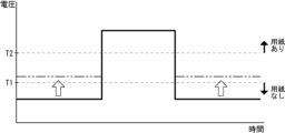
制御部20は、光電センサー36の出力に応じて経路対向面部37等の上における用紙Pの有無を判定する。制御部20の記憶部22には、光電センサー36の出力の閾値が記憶されている。具体的には、図2に示すように、記憶部22は、経路対向面部37等の上に用紙Pが存在しないと判定する第1の閾値T1と、経路対向面部37等の上に用紙Pが存在すると判定する第2の閾値T2と、を記憶(格納)している。第1の閾値T1は、第2の閾値T2よりも高い値に設定されている(図6参照)。なお、本明細書において、「経路対向面部37等の上(対向面部上)」に用紙Pが存在する(しない)等との表現は、現実に用紙Pが経路対向面部37等の上方に存在する(しない)ことを意味すると共に、用紙Pが下方や側方から経路対向面部37を覆うように対向する(しない)ことも含む意味である。
<Control Unit>
The control unit 20 judges the presence or absence of the paper P on the path-opposing surface 37, etc., according to the output of the photoelectric sensor 36. The memory unit 22 of the control unit 20 stores a threshold value of the output of the photoelectric sensor 36. Specifically, as shown in FIG. 2, the memory unit 22 stores (stores) a first threshold value T1 for judging that the paper P does not exist on the path-opposing surface 37, etc., and a second threshold value T2 for judging that the paper P exists on the path-opposing surface 37, etc. The first threshold value T1 is set to a value higher than the second threshold value T2 (see FIG. 6). In this specification, the expression that the paper P exists (is not) on "above the path-opposing surface 37, etc. (on the opposing surface)" means that the paper P actually exists (is not) above the path-opposing surface 37, etc., and also includes the meaning that the paper P faces the path-opposing surface 37 so as to cover it from below or from the side.

制御部20は、光電センサー36から出力された電気信号(電圧)と記憶部22に格納された各種閾値T1,T2とを比較して用紙Pの有無を判定する判定部24を有している。判定部24は、制御部20の機能として提供されるものであり、記憶部22に記憶されたプログラムやデータに従って演算処理部21が演算処理を実行することによって実現される。 The control unit 20 has a determination unit 24 that determines the presence or absence of paper P by comparing the electrical signal (voltage) output from the photoelectric sensor 36 with various threshold values T1, T2 stored in the memory unit 22. The determination unit 24 is provided as a function of the control unit 20, and is realized by the calculation processing unit 21 executing calculation processing according to the programs and data stored in the memory unit 22.

[光電センサーの出力]
例えば、図4に示すように、経路対向面部37等の上に用紙Pが存在しない場合、光電センサー36の投光部36Aから出射された光は経路対向面部37等で反射し、その反射光は光電センサー36の受光部36Bに入射する。経路対向面部37等は光を反射し難くなっているため、反射光の光量は非常に小さくなる。したがって、光電センサー36は、経路対向面部37等の上に用紙Pが存在しないことを示す第1の閾値T1以上の電圧を出力する(図6に示す実線参照)。なお、図6では、説明の便宜のため、光電センサー36の出力(電圧)を直線で示しているが、実際には、光電センサー36はアナログセンサーであるため、光電センサー36の出力は不規則に振動する波形となる。
[Photoelectric sensor output]
For example, as shown in Fig. 4, when no paper P is present on the path-facing surface 37, the light emitted from the light-emitting portion 36A of the photoelectric sensor 36 is reflected by the path-facing surface 37, and the reflected light is incident on the light-receiving portion 36B of the photoelectric sensor 36. Since the path-facing surface 37 does not easily reflect light, the amount of reflected light is very small. Therefore, the photoelectric sensor 36 outputs a voltage equal to or greater than the first threshold T1 indicating that no paper P is present on the path-facing surface 37 (see the solid line in Fig. 6). Note that, for convenience of explanation, the output (voltage) of the photoelectric sensor 36 is shown as a straight line in Fig. 6, but in reality, since the photoelectric sensor 36 is an analog sensor, the output of the photoelectric sensor 36 has an irregularly oscillating waveform.

一方、図5に示すように、経路対向面部37等の上に用紙Pが存在する場合、光電センサー36の投光部36Aから出射された光は用紙Pで反射し、その反射光は光電センサー36の受光部36Bに入射する。用紙Pは経路対向面部37等よりも光を反射し易いため、このときの反射光は経路対向面部37等で反射した場合の反射光よりも大きな光量となる。したがって、光電センサー36は、経路対向面部37等の上に用紙Pが存在することを示す第2の閾値T2以下の電圧を出力する(図6に示す実線参照)。なお、判定部24は、第2の閾値T2以下の電圧の出力後から計測した時間が所定時間を経過したかを判定し、所定時間が経過した後にも第2の閾値T2以下の電圧が出力されている場合にジャムが発生していると判定する。また、時間を計測するタイマー機能は、制御部20の機能として提供される。また、ジャム判定用の所定時間は、予め設定され、記憶部22に記憶されている。 On the other hand, as shown in FIG. 5, when a sheet P is present on the path-facing surface 37, the light emitted from the light-emitting section 36A of the photoelectric sensor 36 is reflected by the sheet P, and the reflected light is incident on the light-receiving section 36B of the photoelectric sensor 36. Since the sheet P is more likely to reflect light than the path-facing surface 37, the reflected light at this time has a larger amount of light than the reflected light reflected by the path-facing surface 37. Therefore, the photoelectric sensor 36 outputs a voltage equal to or less than the second threshold T2 indicating that the sheet P is present on the path-facing surface 37 (see the solid line shown in FIG. 6). The determination section 24 determines whether the time measured after the output of the voltage equal to or less than the second threshold T2 has elapsed a predetermined time, and determines that a jam has occurred if a voltage equal to or less than the second threshold T2 is still output after the predetermined time has elapsed. In addition, a timer function for measuring time is provided as a function of the control section 20. In addition, the predetermined time for jam determination is set in advance and stored in the memory section 22.

ところで、画像形成処理を繰り返すと、搬送ベルト14や経路対向面部37が紙粉やインク等で汚れ、経路対向面部37等での反射光の光量が増加し、光電センサー36の出力が低下することがある(図6の白抜き矢印参照)。すると、図6に二点鎖線で示すように、光電センサー36は、第1の閾値T1よりも低く、第2の閾値T2よりも高い電圧を出力することがある。判定部24は、光電センサー36の出力が第1の閾値T1と第2の閾値T2との間となる場合に経路対向面部37等に反射光の光量を増加させる汚染が生じていると判定する。すなわち、第1の閾値T1と第2の閾値T2とに挟まれた範囲の値は、経路対向面部37等のメンテナンスが必要になったことを示す閾値を含んでいる。なお、経路対向面部37等のメンテナンスとは、例えば、経路対向面部37等の清掃や経路対向面部37等の交換等である。 However, when the image forming process is repeated, the conveyor belt 14 and the path-facing surface 37 may become dirty with paper powder, ink, etc., and the amount of reflected light on the path-facing surface 37, etc. may increase, causing the output of the photoelectric sensor 36 to decrease (see the white arrow in FIG. 6). Then, as shown by the two-dot chain line in FIG. 6, the photoelectric sensor 36 may output a voltage lower than the first threshold T1 and higher than the second threshold T2. When the output of the photoelectric sensor 36 is between the first threshold T1 and the second threshold T2, the determination unit 24 determines that contamination that increases the amount of reflected light has occurred on the path-facing surface 37, etc. That is, the value in the range between the first threshold T1 and the second threshold T2 includes a threshold indicating that maintenance of the path-facing surface 37, etc. is required. Note that maintenance of the path-facing surface 37, etc., is, for example, cleaning of the path-facing surface 37, etc., replacement of the path-facing surface 37, etc., etc.

[ジャム検出方法]
次に、図7を参照して、ジャム検出部35を用いたジャム検出方法(ジャム検出処理)の一例について説明する。図7はジャム検出方法を示すフローチャートである。なお、制御部20は、画像形成処理と並行してジャム検出方法(ジャム検出処理)を実行する。また、制御部20は、全ての光電センサー36の出力に対してジャム検出処理を実行するが、以下の説明では、1つの光電センサー36の出力に対するジャム検出処理について説明する。
[Jam detection method]
Next, an example of a jam detection method (jam detection process) using the jam detection unit 35 will be described with reference to Fig. 7. Fig. 7 is a flowchart showing the jam detection method. The control unit 20 executes the jam detection method (jam detection process) in parallel with the image formation process. The control unit 20 executes the jam detection process for the outputs of all the photoelectric sensors 36, but in the following description, the jam detection process for the output of one photoelectric sensor 36 will be described.

まず、制御部20は、光電センサー36から出力される電圧(電気信号)を受信する(S1)。光電センサー36からの電気信号は、アナログ-デジタル変換(A/D変換)されて記憶部22や演算処理部21のキャッシュメモリー等に記憶される。なお、制御部20は、画像形成処理の開始から終了までの間、所定の時間間隔で光電センサー36から電気信号を受信し続ける。 First, the control unit 20 receives a voltage (electrical signal) output from the photoelectric sensor 36 (S1). The electrical signal from the photoelectric sensor 36 is analog-to-digital converted (A/D converted) and stored in the storage unit 22, the cache memory of the calculation processing unit 21, or the like. The control unit 20 continues to receive the electrical signal from the photoelectric sensor 36 at a predetermined time interval from the start to the end of the image formation process.

次に、判定部24は、記憶された電気信号と第1の閾値T1とを比較する(S2)。当該電気信号(電圧)が第1の閾値T1以上である場合(S2でYES)、判定部24は搬送ベルト14や第1~第3の搬送経路6~8に用紙Pが存在しないと判定し、光電センサー36の出力の受信(S1)に戻る。 Next, the determination unit 24 compares the stored electrical signal with the first threshold value T1 (S2). If the electrical signal (voltage) is equal to or greater than the first threshold value T1 (YES in S2), the determination unit 24 determines that no paper P is present on the conveyor belt 14 or the first to third conveyor paths 6 to 8, and returns to receiving the output of the photoelectric sensor 36 (S1).

一方、当該電気信号が第1の閾値T1未満である場合(S2でNO)、判定部24は当該電気信号と第2の閾値T2とを比較する(S3)。当該電気信号(電圧)が第2の閾値T2以下である場合(S3でYES)、判定部24は、時間の計測を開始し、計測した時間(Tp)が所定時間(T)を経過したか否かを判定する(S4)。計測した時間(Tp)が所定時間(T)を経過していない場合(Tp≦T(S4でNO))、光電センサー36の出力の受信(S1)に戻り、再び上記したS2、S3の判定を実行する。 On the other hand, if the electrical signal is less than the first threshold T1 (NO in S2), the determination unit 24 compares the electrical signal with the second threshold T2 (S3). If the electrical signal (voltage) is equal to or less than the second threshold T2 (YES in S3), the determination unit 24 starts measuring time and determines whether the measured time (Tp) has passed the predetermined time (T) (S4). If the measured time (Tp) has not passed the predetermined time (T) (Tp≦T (NO in S4)), the process returns to receiving the output of the photoelectric sensor 36 (S1) and executes the determinations in S2 and S3 described above again.

一方、計測した時間(Tp)が所定時間(T)を経過した場合(Tp>T(S4でYES))、判定部24は、当該光電センサー36の周辺においてジャムが発生したと判定し、その判定結果を記憶部22に記憶する。制御部20は、画像形成処理を直ちに停止(中断)させ(S5)、ジャムの発生およびジャムの発生位置等を示す情報(文字列や絵図等)を表示部19に表示させる(S6)。 On the other hand, if the measured time (Tp) has passed the predetermined time (T) (Tp>T (YES in S4)), the determination unit 24 determines that a jam has occurred in the vicinity of the photoelectric sensor 36, and stores the determination result in the memory unit 22. The control unit 20 immediately stops (interrupts) the image formation process (S5), and causes the display unit 19 to display information (such as a character string or a picture) indicating the occurrence of the jam and the location of the jam (S6).

ユーザーは、表示部19に表示された情報を参考にし、カバー30等のハウジング2に設けられたドアを開き、詰まった用紙Pを除去する(ジャム処理を行う)。なお、制御部20は、ハウジング2のドアの開閉検知や光電センサー36の出力結果等に基づいてジャム処理が行われたことを判定し、記憶部22に記憶されたジャム発生の判定結果を削除し、表示部19の表示を通常表示に戻し、中断された画像形成処理を再開する。 The user refers to the information displayed on the display unit 19 and opens a door on the housing 2, such as the cover 30, to remove the jammed paper P (perform jam clearance). The control unit 20 determines that jam clearance has been performed based on the detection of the opening and closing of the door of the housing 2 and the output result of the photoelectric sensor 36, deletes the jam occurrence determination result stored in the memory unit 22, returns the display on the display unit 19 to the normal display, and resumes the interrupted image formation process.

光電センサー36からの電気信号と第2の閾値T2とを比較(S3)に戻って、当該電気信号(電圧)が第1の閾値T1未満、且つ第2の閾値T2を越える場合(S3でNO)、判定部24は経路対向面部37等に汚染が生じていると判定し、その判定結果を記憶部22に記憶する。制御部20は、経路対向面部37等のメンテナンスが必要であることを示す情報(文字列や絵図等)を表示部19に表示させる(S7)。なお、経路対向面部37等に汚染が生じていると判定した場合、制御部20は、画像形成処理を中断しないが、画像形成処理を中断するようにしてもよい。また、経路対向面部37等に汚染が生じていると判定した場合、制御部20は、新規の画像形成処理の実行を禁止しないが、新規の画像形成処理を禁止するようにしてもよい。 Returning to the comparison (S3) of the electrical signal from the photoelectric sensor 36 with the second threshold T2, if the electrical signal (voltage) is less than the first threshold T1 and exceeds the second threshold T2 (NO in S3), the determination unit 24 determines that contamination has occurred on the path-facing surface 37, etc., and stores the determination result in the memory unit 22. The control unit 20 causes the display unit 19 to display information (characters, pictures, etc.) indicating that maintenance of the path-facing surface 37, etc. is required (S7). Note that, when it is determined that contamination has occurred on the path-facing surface 37, etc., the control unit 20 does not interrupt the image formation process, but may interrupt the image formation process. Also, when it is determined that contamination has occurred on the path-facing surface 37, etc., the control unit 20 does not prohibit the execution of a new image formation process, but may prohibit a new image formation process.

ユーザーは、表示部19に表示された情報を参考にし、カバー30等のハウジング2に設けられたドアを開き、搬送ベルト14や経路対向面部37の清掃等のメンテナンスを行う。なお、制御部20は、ハウジング2のドアの開閉検知や光電センサー36の出力結果等に基づいてメンテナンスが行われたことを判定し、記憶部22に記憶された汚染発生の判定結果を削除し、表示部19の表示を通常表示に戻す。 The user refers to the information displayed on the display unit 19 and opens a door provided on the housing 2, such as the cover 30, and performs maintenance such as cleaning the conveyor belt 14 and the path-facing surface portion 37. The control unit 20 determines that maintenance has been performed based on the detection of the opening and closing of the door of the housing 2 and the output result of the photoelectric sensor 36, deletes the determination result of the contamination occurrence stored in the memory unit 22, and returns the display on the display unit 19 to the normal display.

また、ユーザーが清掃を行った後も、経路対向面部37等に汚染が生じていると判定される場合、制御部20は、経路対向面部37等を交換する必要があることを示す情報を表示部19に表示させる。なお、経路対向面部37等を交換作業は、専門の作業者によって行われることが好ましい。 In addition, if it is determined that the path-facing surface portion 37, etc. is still contaminated after the user has cleaned it, the control unit 20 causes the display unit 19 to display information indicating that the path-facing surface portion 37, etc. needs to be replaced. Note that it is preferable that the replacement work of the path-facing surface portion 37, etc. be performed by a specialized worker.

以上説明した本実施形態に係る画像形成装置1によれば、経路対向面部37等上に用紙Pが存在しないにも関わらず光電センサー36の出力が第1の閾値T1よりも低くなったことを検出することで、経路対向面部37等が紙粉やインク等で汚れていると推定することができる。これにより、経路対向面部37等の清掃を行う時期を検出することができる。その結果、紙詰まり(ジャム)等、画像形成装置1を停止させるような不具合が発生する前に、経路対向面部37等の清掃等のメンテナンスを行うことができる。また、ジャムが発生していないにも関わらず、誤ってジャムを検出してしまうこと(誤検知)を抑制することができる。さらに、ジャム検出用の光電センサー36を、経路対向面部37等の汚染検出に兼用することができる。これにより、経路対向面部37等の汚染を検出する専用のセンサーを別途設ける場合に比べて、経路対向面部37等の周辺の構造を簡素化することができ、製造コストの低減を図ることができる。 According to the image forming device 1 according to the present embodiment described above, by detecting that the output of the photoelectric sensor 36 is lower than the first threshold value T1 even though no paper P is present on the path-facing surface 37, etc., it is possible to estimate that the path-facing surface 37, etc. is contaminated with paper dust, ink, etc. This makes it possible to detect the time to clean the path-facing surface 37, etc. As a result, maintenance such as cleaning the path-facing surface 37, etc. can be performed before a malfunction such as a paper jam occurs that stops the image forming device 1. In addition, it is possible to suppress erroneous detection of a jam even when a jam does not occur (false detection). Furthermore, the photoelectric sensor 36 for jam detection can also be used to detect contamination of the path-facing surface 37, etc. This allows the structure around the path-facing surface 37, etc. to be simplified and manufacturing costs to be reduced compared to the case where a dedicated sensor for detecting contamination of the path-facing surface 37, etc. is separately provided.

また、本実施形態に係る画像形成装置1によれば、経路対向面部37等が汚染されて清掃等のメンテナンスを必要としていることを、表示部19を通じてユーザー等に知らせることができる。これにより、ユーザー等は、ジャム等が発生する前に、経路対向面部37等の清掃等を行うことができる。 In addition, according to the image forming device 1 of this embodiment, the display unit 19 can inform the user that the path-facing surface 37 or the like is contaminated and requires maintenance such as cleaning. This allows the user to clean the path-facing surface 37 or the like before a jam or the like occurs.

[変形例]
次に、図8ないし図14を参照して、本実施形態に係る画像形成装置1の変形例について説明する。図8は第1変形例に係る画像形成装置1の制御部20等を示すブロック図である。図9は第1変形例に係る画像形成装置1のジャム検出方法を示すフローチャートである。図10は第2変形例に係る画像形成装置1の制御部20等を示すブロック図である。図11は第2変形例に係る画像形成装置1の右側の一部であってカバー30の半開き状態を説明する断面図である。図12は第2変形例に係る画像形成装置1の第1の搬送経路6の下流側であってカバー30の半開き状態を説明する断面図である。図13は第2変形例に係る画像形成装置1の光電センサー36の出力を示すグラフである。図14は第3変形例に係る画像形成装置1の光電センサー36の出力を示すグラフである。なお、以下の変形例の説明では、上記した本実施形態に係る画像形成装置1と同一または対応する構成(工程)については同一の符号を付し、同一または対応する構成(工程)の説明は省略する。
[Modification]
Next, with reference to Figs. 8 to 14, modified examples of the image forming apparatus 1 according to the present embodiment will be described. Fig. 8 is a block diagram showing the control unit 20 and the like of the image forming apparatus 1 according to the first modified example. Fig. 9 is a flowchart showing a jam detection method of the image forming apparatus 1 according to the first modified example. Fig. 10 is a block diagram showing the control unit 20 and the like of the image forming apparatus 1 according to the second modified example. Fig. 11 is a cross-sectional view of a part of the right side of the image forming apparatus 1 according to the second modified example, illustrating a half-open state of the cover 30. Fig. 12 is a cross-sectional view of a part of the right side of the image forming apparatus 1 according to the second modified example, illustrating a half-open state of the cover 30 on the downstream side of the first conveying path 6 of the image forming apparatus 1 according to the second modified example. Fig. 13 is a graph showing the output of the photoelectric sensor 36 of the image forming apparatus 1 according to the second modified example. Fig. 14 is a graph showing the output of the photoelectric sensor 36 of the image forming apparatus 1 according to the third modified example. In the following description of the modified examples, the same reference numerals are used for the same or corresponding configurations (steps) as those of the image forming apparatus 1 according to the present embodiment described above, and the description of the same or corresponding configurations (steps) is omitted.

<第1変形例>
上記した本実施形態に係る画像形成装置1では、ユーザーが手作業で経路対向面部37等を清掃していた。これに対し、第1変形例に係る画像形成装置1は、例えば、経路対向面部37等を清掃する清掃部40を更に備えている(図8参照)。
<First Modification>
In the image forming apparatus 1 according to the present embodiment described above, the user manually cleans the path-facing surface 37, etc. In contrast, the image forming apparatus 1 according to the first modified example further includes, for example, a cleaning unit 40 that cleans the path-facing surface 37, etc. (see FIG. 8 ).

清掃部40は、搬送ベルト14の表面や経路対向面部37の平面に接触する清掃部材と、清掃部材を回転または往復直線移動させる駆動部と、を有している(図示せず)。清掃部材は、例えば、外周部がウェスやブラシで構成された清掃ローラーであってもよいし、弾性変形するブレードであってもよい(図示せず)。駆動部は、電動モーターやソレノイド等の駆動源と、駆動源と清掃部材とを連結するギア列やカム等の動力伝達機構と、を有している(図示せず)。駆動部は、制御部20(インターフェース部23)に電気的に接続され、制御部20によって制御されながら作動する。例えば、駆動部は、清掃ローラーを経路対向面部37等に接触する位置まで移動させ、清掃ローラーを軸周りに回転させる。他にも、駆動部は、ブレードを経路対向面部37等に接触する位置まで移動させ、ブレードを往復直線移動させる。このようにして、搬送ベルト14の表面や経路対向面部37の平面に付着した紙粉やインク等の汚れが除去される。 The cleaning unit 40 has a cleaning member that contacts the surface of the conveyor belt 14 and the flat surface of the path-facing surface 37, and a drive unit that rotates or moves the cleaning member back and forth (not shown). The cleaning member may be, for example, a cleaning roller whose outer periphery is made of a rag or a brush, or a blade that elastically deforms (not shown). The drive unit has a drive source such as an electric motor or a solenoid, and a power transmission mechanism such as a gear train or a cam that connects the drive source and the cleaning member (not shown). The drive unit is electrically connected to the control unit 20 (interface unit 23) and operates under the control of the control unit 20. For example, the drive unit moves the cleaning roller to a position where it contacts the path-facing surface 37, etc., and rotates the cleaning roller around its axis. In addition, the drive unit moves the blade to a position where it contacts the path-facing surface 37, etc., and moves the blade back and forth in a straight line. In this way, dirt such as paper dust and ink attached to the surface of the conveyor belt 14 and the flat surface of the path-facing surface 37 is removed.

図9に示すように、ジャム検出方法(ジャム検出処理)において、判定部24は経路対向面部37等に汚染が生じていると判定した場合(S3でNO)、その判定結果を記憶部22に記憶する。制御部20は、経路対向面部37等のメンテナンスが必要であることを示す情報を表示部19に表示させ(S7)、画像形成処理の終了を待つ(S8でNO)。画像形成処理が終了した場合(S8でYES)。制御部20は、経路対向面部37等の清掃を清掃部40に実行させる(S9)。なお、制御部20は、清掃部40による清掃が終了した後、記憶部22に記憶された汚染発生の判定結果を削除し、表示部19の表示を通常表示に戻す。また、清掃部40が清掃を行った後も、経路対向面部37等に汚染が生じていると判定される場合、制御部20は、経路対向面部37等を交換する必要があることを示す情報を表示部19に表示させる。 9, in the jam detection method (jam detection process), when the determination unit 24 determines that the path-facing surface 37, etc. is contaminated (NO in S3), the determination result is stored in the storage unit 22. The control unit 20 causes the display unit 19 to display information indicating that maintenance of the path-facing surface 37, etc. is required (S7), and waits for the image formation process to end (NO in S8). When the image formation process ends (YES in S8), the control unit 20 causes the cleaning unit 40 to clean the path-facing surface 37, etc. (S9). After the cleaning unit 40 has finished cleaning, the control unit 20 deletes the determination result of the occurrence of contamination stored in the storage unit 22, and returns the display of the display unit 19 to the normal display. In addition, when it is determined that the path-facing surface 37, etc. is contaminated even after the cleaning unit 40 has performed cleaning, the control unit 20 causes the display unit 19 to display information indicating that the path-facing surface 37, etc. needs to be replaced.

以上説明した本実施形態の第1変形例に係る画像形成装置1によれば、清掃部40によって自動で経路対向面部37等の清掃を行うことができる。これにより、ユーザーが手作業で清掃作業を行う手間を省略することができる。 According to the image forming device 1 according to the first modified example of the present embodiment described above, the cleaning unit 40 can automatically clean the path-facing surface 37 and the like. This eliminates the need for the user to perform the cleaning work manually.

なお、制御部20は、経路対向面部37等に汚染が生じていると判定した場合に、清掃部40による清掃とユーザーの手作業による清掃のいずれかを選択させるボタン等を表示部19に表示させてもよい(図示せず)。 When the control unit 20 determines that contamination has occurred on the path-facing surface portion 37 or the like, it may cause the display unit 19 to display buttons or the like that allow the user to select between cleaning by the cleaning unit 40 or manual cleaning by the user (not shown).

なお、第1変形例に係る画像形成装置1では、清掃部40が経路対向面部37等に接触しながら動くことで清掃を行っていたが、本発明はこれに限定されない。例えば、清掃部は、空気を圧縮する圧空源と、経路対向面部37等に圧縮空気を吹き付けるノズルと、を有していてもよい(図示せず)。清掃部が経路対向面部37等に空気を吹き付けることで、経路対向面部37等に付着した汚れを落としてもよい。 In the image forming device 1 according to the first modified example, the cleaning unit 40 moves while in contact with the path-facing surface portion 37 and the like to perform cleaning, but the present invention is not limited to this. For example, the cleaning unit may have a compressed air source that compresses air, and a nozzle that blows compressed air against the path-facing surface portion 37 and the like (not shown). The cleaning unit may blow air against the path-facing surface portion 37 and the like to remove dirt adhering to the path-facing surface portion 37 and the like.

<第2変形例>
第2変形例に係る画像形成装置1は、カバー30の対向搬送部材6B,8Bに設けられた経路対向面部37の少なくともいずれか1つと、この経路対向面部37に対向した光電センサー36とによって、カバー30の半開き状態を検出する構成となっている。カバー30の半開き状態とは、所謂半ドア状態であって、カバー30がハウジング2の側面を閉じて開放不能な状態であるが、完全に閉じられていない状態(図11参照)を意味する。図11および図12では、一例として、第1の搬送経路6の下流側に設けた光電センサー36と経路対向面部37とでカバー30の半開き状態を検出する構成となっている。
<Second Modification>
The image forming apparatus 1 according to the second modification is configured to detect the half-open state of the cover 30 by at least one of the path-facing surface portions 37 provided on the opposing conveying members 6B and 8B of the cover 30 and a photoelectric sensor 36 facing the path-facing surface portion 37. The half-open state of the cover 30 means a so-called half-door state, in which the cover 30 closes the side surface of the housing 2 and cannot be opened, but is not completely closed (see FIG. 11). In FIG. 11 and FIG. 12, as an example, the half-open state of the cover 30 is detected by the photoelectric sensor 36 provided on the downstream side of the first conveying path 6 and the path-facing surface portion 37.

図10に示すように、制御部20の記憶部22には、第1の閾値T1および第2の閾値T2に加えて、第3の閾値T3が記憶されている。第3の閾値T3は、第1の閾値T1よりも高い値に設定されている(図13参照)。換言すれば、第3の閾値T3は、第1の閾値T1を挟んで第2の閾値T2とは反対側で、且つ第1の閾値T1から所定範囲外となる値に設定されている。第3の閾値T3は、カバー30が半開き状態であると判定するための閾値である。 As shown in FIG. 10, in addition to the first threshold value T1 and the second threshold value T2, the memory unit 22 of the control unit 20 stores a third threshold value T3. The third threshold value T3 is set to a value higher than the first threshold value T1 (see FIG. 13). In other words, the third threshold value T3 is set to a value on the opposite side of the first threshold value T1 from the second threshold value T2 and outside a predetermined range from the first threshold value T1. The third threshold value T3 is a threshold value for determining that the cover 30 is in a half-open state.

経路対向面部37等の上に用紙Pが存在せず、カバー30が半開き状態である場合(図11参照)、カバー30が完全に閉じている場合に比べて、光電センサー36と経路対向面部37との距離が僅かに長くなる(図12参照)。図12に示す二点鎖線は、カバー30を完全に閉じた場合における経路対向面部37の位置である。したがって、カバー30が完全に閉じている場合よりも、経路対向面部37等で反射した反射光は弱くなり(光量減少)、図13に示すように、光電センサー36は第1の閾値T1よりも高く設定された第3の閾値T3を超える電圧を出力する。制御部20の判定部24は、第3の閾値T3を越えた場合にカバー30が開き状態であると判定する。なお、光電センサー36の出力が第1の閾値T1以上、第3の閾値T3以下である場合に、判定部24は経路対向面部37等の上に用紙Pが存在しないと判定する。 When there is no paper P on the path-facing surface 37 and the cover 30 is half-open (see FIG. 11), the distance between the photoelectric sensor 36 and the path-facing surface 37 is slightly longer than when the cover 30 is completely closed (see FIG. 12). The two-dot chain line in FIG. 12 indicates the position of the path-facing surface 37 when the cover 30 is completely closed. Therefore, the reflected light reflected by the path-facing surface 37 is weaker (light intensity reduction) than when the cover 30 is completely closed, and as shown in FIG. 13, the photoelectric sensor 36 outputs a voltage that exceeds the third threshold T3 set higher than the first threshold T1. The determination unit 24 of the control unit 20 determines that the cover 30 is open when the third threshold T3 is exceeded. When the output of the photoelectric sensor 36 is equal to or greater than the first threshold T1 and equal to or less than the third threshold T3, the determination unit 24 determines that there is no paper P on the path-facing surface 37.

制御部20は画像形成処理を実行する前に光電センサー36から電気信号(電圧)を受信し、当該電気信号が第3の閾値T3を越えている場合、判定部24は、カバー30が半開き状態であると判定する。この場合、制御部20は、画像形成処理を実行せず、カバー30が完全に閉じられていないことを示す情報を表示部19に表示させる。ユーザーは、表示部19に表示された情報を参考にし、半開きになったカバー30を完全に閉じる。 The control unit 20 receives an electrical signal (voltage) from the photoelectric sensor 36 before executing the image formation process, and if the electrical signal exceeds the third threshold value T3, the determination unit 24 determines that the cover 30 is half-open. In this case, the control unit 20 does not execute the image formation process, and causes the display unit 19 to display information indicating that the cover 30 is not completely closed. The user refers to the information displayed on the display unit 19 and completely closes the half-open cover 30.

なお、制御部20は、当該電気信号が第1の閾値T1以上、第3の閾値T3以下である場合に画像形成処理を実行し、画像形成処理と並行して上記したジャム検出方法(ジャム検出処理)を実行する。原則として、画像形成処理の実行中にカバー30が開かれることはないため、ジャム検出処理が実行されている間は、光電センサー36からの電気信号が第3の閾値T3を越えることはない。 The control unit 20 executes the image formation process when the electrical signal is equal to or greater than the first threshold T1 and equal to or less than the third threshold T3, and executes the jam detection method (jam detection process) described above in parallel with the image formation process. As a rule, the cover 30 is not opened while the image formation process is being performed, so the electrical signal from the photoelectric sensor 36 does not exceed the third threshold T3 while the jam detection process is being performed.

以上説明した本実施形態の第2変形例に係る画像形成装置1によれば、ジャム検出および経路対向面部37の汚染検出を行うための光電センサー36を、カバー30の半開き検出に兼用することができる。これにより、カバー30の半開きを検出する専用のセンサーを別途設ける場合に比べて、カバー30の周辺の構造を簡素化することができ、製造コストの低減を図ることができる。 According to the image forming device 1 according to the second modified example of this embodiment described above, the photoelectric sensor 36 for detecting jams and contamination of the path-facing surface portion 37 can also be used to detect whether the cover 30 is half-open. This simplifies the structure around the cover 30 and reduces manufacturing costs compared to when a separate sensor dedicated to detecting whether the cover 30 is half-open is provided.

また、第2変形例に係る画像形成装置1によれば、カバー30が適正に閉じられていないことを、表示部19を通じてユーザー等に知らせることができる。これにより、ユーザー等は、半開きになっているカバー30を適正に閉じることができる。 In addition, the image forming device 1 according to the second modified example can inform the user, etc., through the display unit 19 that the cover 30 is not properly closed. This allows the user, etc., to properly close the half-open cover 30.

なお、第2変形例に係る画像形成装置1の特徴は、第1変形例に係る画像形成装置1に適用されてもよい。 The features of the image forming device 1 according to the second modified example may be applied to the image forming device 1 according to the first modified example.

<第3変形例>
上記した本実施形態(第1~第2変形例を含む。)に係る画像形成装置1では、光電センサー36の出力(電圧)が受光量(反射光の光量)に反比例して増減していたが、本発明はこれに限定されない。図14に示すように、出力(電圧)が受光量(反射光の光量)に比例して増減するような光電センサー36を採用してもよい(第3変形例)。すなわち、光電センサー36は、受光量(反射光の光量)の増加に伴って出力(電圧)を増加させる仕様であってもよい。この仕様では、第1の閾値T1は、第2の閾値T2よりも低い値に設定される。そして、経路対向面部37等の上に用紙Pが存在しない場合に光電センサー36は第1の閾値T1以下の電圧を出力し、経路対向面部37等の上に用紙Pが存在する場合に光電センサー36は第2の閾値T2以上の電圧を出力する。また、光電センサー36が第1の閾値T1よりも高く、第2の閾値T2よりも低い電圧を出力した場合、判定部24は、経路対向面部37等に汚染が生じていると判定する。また、第3の閾値T3は、第1の閾値T1よりも低い値に設定されている(図示せず)。
<Third Modification>
In the image forming apparatus 1 according to the present embodiment (including the first and second modified examples) described above, the output (voltage) of the photoelectric sensor 36 increases and decreases in inverse proportion to the amount of received light (amount of reflected light), but the present invention is not limited to this. As shown in FIG. 14, a photoelectric sensor 36 whose output (voltage) increases and decreases in proportion to the amount of received light (amount of reflected light) may be adopted (third modified example). That is, the photoelectric sensor 36 may be designed to increase the output (voltage) as the amount of received light (amount of reflected light) increases. In this specification, the first threshold T1 is set to a value lower than the second threshold T2. Then, when no paper P is present on the path facing surface 37 or the like, the photoelectric sensor 36 outputs a voltage equal to or lower than the first threshold T1, and when paper P is present on the path facing surface 37 or the like, the photoelectric sensor 36 outputs a voltage equal to or higher than the second threshold T2. Furthermore, when the photoelectric sensor 36 outputs a voltage higher than the first threshold T1 and lower than the second threshold T2, the determination unit 24 determines that contamination has occurred on the path facing surface 37, etc. Furthermore, the third threshold T3 is set to a value lower than the first threshold T1 (not shown).

なお、本実施形態(第1~第3変形例を含む。以下同じ。)の説明において示したジャム検出方法(ジャム検出処理)は一例であり、矛盾の無い範囲で各工程(各手順)の順序を入れ替えてもよい。 Note that the jam detection method (jam detection process) described in the present embodiment (including the first to third modified examples; the same applies below) is just an example, and the order of each step (each procedure) may be changed as long as there is no inconsistency.

また、本実施形態に係る画像形成装置1では、カバー30がハウジング2の右側面に設けられていたが、これに限らず、ハウジング2の左側面、前側面、後側面、上面等にカバーが開閉可能に設けられてもよい(図示せず)。これらのカバーが第1~第3の搬送経路6~8のいずれかを構成し、これらのカバーに経路対向面部37が設けられている場合には、光電センサー36の出力結果からカバーの半開き状態を検出することもできる。 In addition, in the image forming device 1 according to this embodiment, the cover 30 is provided on the right side of the housing 2, but this is not limiting, and a cover may be provided on the left side, front side, rear side, top side, etc. of the housing 2 so that it can be opened and closed (not shown). When these covers form any of the first to third transport paths 6 to 8 and are provided with a path-facing surface portion 37, the half-open state of the cover can also be detected from the output result of the photoelectric sensor 36.

また、本実施形態に係る画像形成装置1では、カバー30の対向搬送部材6B,8Bに経路対向面部37が設けられ、本体側搬送部材6A,8Aに光電センサー36が設けられていたが、本発明はこれに限定されない。これとは逆に、カバー30の対向搬送部材6B,8Bに光電センサー36が設けられ、本体側搬送部材6A,8Aに経路対向面部37が設けられてもよい(図示せず)。 In addition, in the image forming device 1 according to the present embodiment, the opposing conveying members 6B, 8B of the cover 30 are provided with the path-facing surface portion 37, and the main body-side conveying members 6A, 8A are provided with the photoelectric sensor 36, but the present invention is not limited to this. Conversely, the opposing conveying members 6B, 8B of the cover 30 may be provided with the photoelectric sensor 36, and the main body-side conveying members 6A, 8A may be provided with the path-facing surface portion 37 (not shown).

また、本実施形態に係る画像形成装置1では、ジャムの発生、経路対向面部37等の汚染およびカバー30の半開き等の情報(警告)が表示部19に表示されていたが、本発明はこれに限定されない。例えば、画像形成装置1にスピーカー(図示せず)を設け、制御部20は、上記した情報を表示部19に表示することに加えて、上記した情報に対応する警告音や音声をスピーカーから流す制御を実行してもよい。 In addition, in the image forming device 1 according to this embodiment, information (warnings) such as the occurrence of a jam, contamination of the path facing surface portion 37, and the half-open cover 30 are displayed on the display unit 19, but the present invention is not limited to this. For example, the image forming device 1 may be provided with a speaker (not shown), and the control unit 20 may execute control to play a warning sound or voice corresponding to the above information from the speaker in addition to displaying the above information on the display unit 19.

また、本実施形態に係る画像形成装置1では、カバー30の回動軸31がハウジング2の下部で水平方向に設けられていたが、これに限らず、回動軸31は、ハウジング2(カバー30)の左右方向の何れか一方で垂直方向に設けられてもよい(図示せず)。 In addition, in the image forming device 1 according to this embodiment, the pivot shaft 31 of the cover 30 is arranged horizontally at the bottom of the housing 2, but this is not limited thereto, and the pivot shaft 31 may be arranged vertically on either the left or right side of the housing 2 (cover 30) (not shown).

また、本実施形態に係る画像形成装置1は、カラープリンターであったが、これに限らず、モノクロプリンター、コピー機、ファクシミリ等であってもよい。また、画像形成装置1は、インクジェット式のプリンターであったが、これに限らず、電子写真式の画像形成装置(プリンター、コピー機、ファクシミリ等)であってもよく、経路対向面部37が紙粉やトナー等で汚れたことを検出するようにしてもよい(図示せず)。 In addition, the image forming device 1 according to this embodiment is a color printer, but is not limited to this and may be a monochrome printer, a copier, a facsimile, etc. Also, the image forming device 1 is an inkjet printer, but is not limited to this and may be an electrophotographic image forming device (printer, copier, facsimile, etc.), and may be configured to detect when the path facing surface portion 37 is soiled with paper dust, toner, etc. (not shown).

なお、上記実施形態の説明は、本発明に係る画像形成装置における一態様を示すものであって、本発明の技術範囲は、上記実施態様に限定されるものではない。本発明は技術的思想の趣旨を逸脱しない範囲において様々に変更、置換、変形されてもよく、特許請求の範囲は技術的思想の範囲内に含まれ得る全ての実施態様を含んでいる。 The above description of the embodiment shows one aspect of the image forming device according to the present invention, and the technical scope of the present invention is not limited to the above embodiment. The present invention may be modified, substituted, or altered in various ways without departing from the spirit of the technical idea, and the claims include all embodiments that may be included within the scope of the technical idea.

1 画像形成装置
2 ハウジング
14 搬送ベルト(対向面部)
18 制御部
19 表示部
30 カバー
36 光電センサー
37 経路対向面部(対向面部)
40 清掃部
P 用紙
T1 第1の閾値
T2 第2の閾値
1 Image forming apparatus 2 Housing 14 Conveyor belt (opposing surface portion)
18 Control unit 19 Display unit 30 Cover 36 Photoelectric sensor 37 Path facing surface portion (facing surface portion)
40 Cleaning unit P Paper T1 First threshold T2 Second threshold

Claims (4)

対向面部および前記対向面部上の用紙を含む被検出物に向けて投光し、前記被検出物で反射した反射光を受光し、前記反射光の光量に応じた電気信号を出力する反射型の光電センサーと、
前記光電センサーの出力に応じて前記対向面部上における前記用紙の有無を判定する制御部であって、前記光電センサーの出力の閾値として、前記対向面部上に前記用紙が存在しないと判定する第1の閾値と、前記対向面部上に前記用紙が存在すると判定する第2の閾値と、を記憶し、前記光電センサーの出力が前記第1の閾値と前記第2の閾値との間となる場合に前記対向面部に前記反射光の光量を増加させる汚染が生じていると判定する制御部と、
ハウジングに開閉可能に取り付けられ、前記対向面部または前記光電センサーが設けられたカバーと、を備え
前記制御部は、前記光電センサーの出力が前記第1の閾値を挟んで前記第2の閾値とは反対側で、且つ前記第1の閾値から所定範囲外となった場合に前記カバーが完全に閉じられていない半開き状態であると判定することを特徴とする画像形成装置。
a reflective photoelectric sensor that projects light toward an object to be detected, including an opposing surface and a sheet of paper placed on the opposing surface, receives light reflected by the object to be detected, and outputs an electrical signal according to the amount of the reflected light;
a control unit that determines whether or not the paper is present on the facing surface portion according to an output of the photoelectric sensor, the control unit storing a first threshold value for determining that the paper is not present on the facing surface portion and a second threshold value for determining that the paper is present on the facing surface portion as threshold values for the output of the photoelectric sensor, and determining that contamination that increases the amount of reflected light has occurred on the facing surface portion when the output of the photoelectric sensor is between the first threshold value and the second threshold value;
a cover attached to the housing so as to be openable and closable, and having the facing surface portion or the photoelectric sensor provided thereon ;
The control unit determines that the cover is not completely closed and is in a half-open state when the output of the photoelectric sensor is on the opposite side of the first threshold value from the second threshold value and outside a predetermined range of the first threshold value .
情報を表示する表示部を更に備え、
前記制御部は、前記対向面部に汚染が生じていると判定した場合に前記対向面部のメンテナンスが必要であることを示す情報を前記表示部に表示させることを特徴とする請求項1に記載の画像形成装置。
Further comprising a display unit for displaying information,
The image forming apparatus according to claim 1 , wherein the control unit causes the display unit to display information indicating that maintenance of the facing surface is required when it is determined that the facing surface is contaminated.
前記対向面部を清掃する清掃部を更に備え、
前記制御部は、前記対向面部に汚染が生じていると判定した場合に前記対向面部の清掃を前記清掃部に実行させることを特徴とする請求項1または2に記載の画像形成装置。
Further comprising a cleaning unit that cleans the facing surface portion,
3. The image forming apparatus according to claim 1, wherein the control unit causes the cleaning unit to clean the facing surface when it is determined that the facing surface is contaminated.
情報を表示する表示部を更に備え、
前記制御部は、前記カバーが前記半開き状態であると判定した場合に前記カバーが完全に閉じられていないことを示す情報を前記表示部に表示させることを特徴とする請求項1ないし3のいずれか1項に記載の画像形成装置。
Further comprising a display unit for displaying information,
4. The image forming apparatus according to claim 1, wherein the control unit causes the display unit to display information indicating that the cover is not completely closed when the control unit determines that the cover is in the half-open state .
JP2020162191A 2020-09-28 2020-09-28 Image forming device Active JP7574591B2 (en)

Priority Applications (2)

Application Number Priority Date Filing Date Title
JP2020162191A JP7574591B2 (en) 2020-09-28 2020-09-28 Image forming device
US17/486,314 US11660882B2 (en) 2020-09-28 2021-09-27 Image forming apparatus including jam detection part provided with photoelecetric sensor

Applications Claiming Priority (1)

Application Number Priority Date Filing Date Title
JP2020162191A JP7574591B2 (en) 2020-09-28 2020-09-28 Image forming device

Publications (2)

Publication Number Publication Date
JP2022054917A JP2022054917A (en) 2022-04-07
JP7574591B2 true JP7574591B2 (en) 2024-10-29

Family

ID=80822175

Family Applications (1)

Application Number Title Priority Date Filing Date
JP2020162191A Active JP7574591B2 (en) 2020-09-28 2020-09-28 Image forming device

Country Status (2)

Country Link
US (1) US11660882B2 (en)
JP (1) JP7574591B2 (en)

Families Citing this family (1)

* Cited by examiner, † Cited by third party
Publication number Priority date Publication date Assignee Title
JP2023132573A (en) * 2022-03-11 2023-09-22 ブラザー工業株式会社 image recording device

Citations (1)

* Cited by examiner, † Cited by third party
Publication number Priority date Publication date Assignee Title
JP2019025662A (en) 2017-07-26 2019-02-21 キヤノンファインテックニスカ株式会社 Conveyance device and image formation apparatus

Family Cites Families (2)

* Cited by examiner, † Cited by third party
Publication number Priority date Publication date Assignee Title
JPS50152739A (en) 1974-05-29 1975-12-09
JP7207929B2 (en) * 2018-10-02 2023-01-18 キヤノン株式会社 Detection device, control method and program

Patent Citations (1)

* Cited by examiner, † Cited by third party
Publication number Priority date Publication date Assignee Title
JP2019025662A (en) 2017-07-26 2019-02-21 キヤノンファインテックニスカ株式会社 Conveyance device and image formation apparatus

Also Published As

Publication number Publication date
US11660882B2 (en) 2023-05-30
US20220097415A1 (en) 2022-03-31
JP2022054917A (en) 2022-04-07

Similar Documents

Publication Publication Date Title
US8045914B2 (en) Image forming apparatus
JP4717571B2 (en) Image forming apparatus
JP4706739B2 (en) Recording device
JP2010266799A (en) Sheet discharging apparatus and image forming apparatus
JP4737565B2 (en) Image forming apparatus and initialization method of image forming apparatus
CN101758664B (en) Ink-jet recording apparatus
JP7574591B2 (en) Image forming device
CN102774672A (en) Feeding apparatus
JP2007145523A (en) Electrostatic transfer device and image forming apparatus
JP4613081B2 (en) Image forming apparatus
JPH07178987A (en) Jam elimination method and control circuit for electrophotographic developing printer
JP4491301B2 (en) Ink jet recording apparatus and control method thereof
JP4408847B2 (en) Image forming apparatus and sheet conveying apparatus
JP2006256864A (en) Image forming apparatus
US11318769B2 (en) Image forming apparatus that cleans both conveyance member and pair of conveyance rollers, sheet conveying device
JP5736973B2 (en) Printing apparatus, optical sensor stain determination method, and optical sensor stain determination program
JP4413131B2 (en) Image forming apparatus
JP4967786B2 (en) Image forming apparatus
JP7334565B2 (en) image forming device
JP2009300864A (en) Image forming apparatus
JP2014149463A (en) Image forming apparatus
JP3950885B2 (en) Image forming apparatus
JP2025158388A (en) Image forming device
JP2006248719A (en) Image forming apparatus
JP2014012584A (en) Image forming apparatus

Legal Events

Date Code Title Description
A621 Written request for application examination

Free format text: JAPANESE INTERMEDIATE CODE: A621

Effective date: 20230828

A977 Report on retrieval

Free format text: JAPANESE INTERMEDIATE CODE: A971007

Effective date: 20240531

A131 Notification of reasons for refusal

Free format text: JAPANESE INTERMEDIATE CODE: A131

Effective date: 20240611

A521 Request for written amendment filed

Free format text: JAPANESE INTERMEDIATE CODE: A523

Effective date: 20240802

TRDD Decision of grant or rejection written
A01 Written decision to grant a patent or to grant a registration (utility model)

Free format text: JAPANESE INTERMEDIATE CODE: A01

Effective date: 20240917

A61 First payment of annual fees (during grant procedure)

Free format text: JAPANESE INTERMEDIATE CODE: A61

Effective date: 20240930

R150 Certificate of patent or registration of utility model

Ref document number: 7574591

Country of ref document: JP

Free format text: JAPANESE INTERMEDIATE CODE: R150