JP7574331B2 - Earphone Core - Google Patents
Earphone Core Download PDFInfo
- Publication number
- JP7574331B2 JP7574331B2 JP2022578983A JP2022578983A JP7574331B2 JP 7574331 B2 JP7574331 B2 JP 7574331B2 JP 2022578983 A JP2022578983 A JP 2022578983A JP 2022578983 A JP2022578983 A JP 2022578983A JP 7574331 B2 JP7574331 B2 JP 7574331B2
- Authority
- JP
- Japan
- Prior art keywords
- fixed
- magnetic
- voice coil
- vibration
- magnetic steel
- Prior art date
- Legal status (The legal status is an assumption and is not a legal conclusion. Google has not performed a legal analysis and makes no representation as to the accuracy of the status listed.)
- Active
Links
Images


Classifications
-
- H—ELECTRICITY
- H04—ELECTRIC COMMUNICATION TECHNIQUE
- H04R—LOUDSPEAKERS, MICROPHONES, GRAMOPHONE PICK-UPS OR LIKE ACOUSTIC ELECTROMECHANICAL TRANSDUCERS; ELECTRIC HEARING AIDS; PUBLIC ADDRESS SYSTEMS
- H04R9/00—Transducers of moving-coil, moving-strip, or moving-wire type
- H04R9/06—Loudspeakers
-
- H—ELECTRICITY
- H04—ELECTRIC COMMUNICATION TECHNIQUE
- H04R—LOUDSPEAKERS, MICROPHONES, GRAMOPHONE PICK-UPS OR LIKE ACOUSTIC ELECTROMECHANICAL TRANSDUCERS; ELECTRIC HEARING AIDS; PUBLIC ADDRESS SYSTEMS
- H04R1/00—Details of transducers, loudspeakers or microphones
- H04R1/06—Arranging circuit leads; Relieving strain on circuit leads
-
- H—ELECTRICITY
- H04—ELECTRIC COMMUNICATION TECHNIQUE
- H04R—LOUDSPEAKERS, MICROPHONES, GRAMOPHONE PICK-UPS OR LIKE ACOUSTIC ELECTROMECHANICAL TRANSDUCERS; ELECTRIC HEARING AIDS; PUBLIC ADDRESS SYSTEMS
- H04R1/00—Details of transducers, loudspeakers or microphones
- H04R1/10—Earpieces; Attachments therefor ; Earphones; Monophonic headphones
- H04R1/1016—Earpieces of the intra-aural type
-
- H—ELECTRICITY
- H04—ELECTRIC COMMUNICATION TECHNIQUE
- H04R—LOUDSPEAKERS, MICROPHONES, GRAMOPHONE PICK-UPS OR LIKE ACOUSTIC ELECTROMECHANICAL TRANSDUCERS; ELECTRIC HEARING AIDS; PUBLIC ADDRESS SYSTEMS
- H04R1/00—Details of transducers, loudspeakers or microphones
- H04R1/10—Earpieces; Attachments therefor ; Earphones; Monophonic headphones
- H04R1/1058—Manufacture or assembly
- H04R1/1075—Mountings of transducers in earphones or headphones
-
- H—ELECTRICITY
- H04—ELECTRIC COMMUNICATION TECHNIQUE
- H04R—LOUDSPEAKERS, MICROPHONES, GRAMOPHONE PICK-UPS OR LIKE ACOUSTIC ELECTROMECHANICAL TRANSDUCERS; ELECTRIC HEARING AIDS; PUBLIC ADDRESS SYSTEMS
- H04R1/00—Details of transducers, loudspeakers or microphones
- H04R1/20—Arrangements for obtaining desired frequency or directional characteristics
- H04R1/22—Arrangements for obtaining desired frequency or directional characteristics for obtaining desired frequency characteristic only
- H04R1/24—Structural combinations of separate transducers or of two parts of the same transducer and responsive respectively to two or more frequency ranges
-
- H—ELECTRICITY
- H04—ELECTRIC COMMUNICATION TECHNIQUE
- H04R—LOUDSPEAKERS, MICROPHONES, GRAMOPHONE PICK-UPS OR LIKE ACOUSTIC ELECTROMECHANICAL TRANSDUCERS; ELECTRIC HEARING AIDS; PUBLIC ADDRESS SYSTEMS
- H04R11/00—Transducers of moving-armature or moving-core type
- H04R11/02—Loudspeakers
-
- H—ELECTRICITY
- H04—ELECTRIC COMMUNICATION TECHNIQUE
- H04R—LOUDSPEAKERS, MICROPHONES, GRAMOPHONE PICK-UPS OR LIKE ACOUSTIC ELECTROMECHANICAL TRANSDUCERS; ELECTRIC HEARING AIDS; PUBLIC ADDRESS SYSTEMS
- H04R19/00—Electrostatic transducers
- H04R19/02—Loudspeakers
-
- H—ELECTRICITY
- H04—ELECTRIC COMMUNICATION TECHNIQUE
- H04R—LOUDSPEAKERS, MICROPHONES, GRAMOPHONE PICK-UPS OR LIKE ACOUSTIC ELECTROMECHANICAL TRANSDUCERS; ELECTRIC HEARING AIDS; PUBLIC ADDRESS SYSTEMS
- H04R9/00—Transducers of moving-coil, moving-strip, or moving-wire type
- H04R9/02—Details
-
- H—ELECTRICITY
- H04—ELECTRIC COMMUNICATION TECHNIQUE
- H04R—LOUDSPEAKERS, MICROPHONES, GRAMOPHONE PICK-UPS OR LIKE ACOUSTIC ELECTROMECHANICAL TRANSDUCERS; ELECTRIC HEARING AIDS; PUBLIC ADDRESS SYSTEMS
- H04R9/00—Transducers of moving-coil, moving-strip, or moving-wire type
- H04R9/02—Details
- H04R9/025—Magnetic circuit
-
- H—ELECTRICITY
- H04—ELECTRIC COMMUNICATION TECHNIQUE
- H04R—LOUDSPEAKERS, MICROPHONES, GRAMOPHONE PICK-UPS OR LIKE ACOUSTIC ELECTROMECHANICAL TRANSDUCERS; ELECTRIC HEARING AIDS; PUBLIC ADDRESS SYSTEMS
- H04R2201/00—Details of transducers, loudspeakers or microphones covered by H04R1/00 but not provided for in any of its subgroups
- H04R2201/003—Mems transducers or their use
-
- H—ELECTRICITY
- H04—ELECTRIC COMMUNICATION TECHNIQUE
- H04R—LOUDSPEAKERS, MICROPHONES, GRAMOPHONE PICK-UPS OR LIKE ACOUSTIC ELECTROMECHANICAL TRANSDUCERS; ELECTRIC HEARING AIDS; PUBLIC ADDRESS SYSTEMS
- H04R2400/00—Loudspeakers
- H04R2400/11—Aspects regarding the frame of loudspeaker transducers
Landscapes
- Engineering & Computer Science (AREA)
- Physics & Mathematics (AREA)
- Acoustics & Sound (AREA)
- Signal Processing (AREA)
- Manufacturing & Machinery (AREA)
- Health & Medical Sciences (AREA)
- Otolaryngology (AREA)
- Electromagnetism (AREA)
- Audible-Bandwidth Dynamoelectric Transducers Other Than Pickups (AREA)
- Electrostatic, Electromagnetic, Magneto- Strictive, And Variable-Resistance Transducers (AREA)
- Headphones And Earphones (AREA)
- Obtaining Desirable Characteristics In Audible-Bandwidth Transducers (AREA)
Description
本発明は、発音デバイスに関し、特にTWSイヤホンに適用されるイヤホンコアに関する。 The present invention relates to a sound producing device, and in particular to an earphone core applied to a TWS earphone.
高品質のスマートフォンやPadなどの携帯型電子製品のロスレス音楽が広く適用されるようになると、人々はそれと組み合わせて応用可能なイヤホンへの要求もますます高くなり、その体格が小型でありながら、様々な音響効果をリアルに再現できる高忠実度の音質性能が求められている。 As lossless music becomes more widely used in high-quality smartphones, iPads and other portable electronic products, people have increasingly high demands for earphones that can be used in combination with them, and there is a demand for earphones that are small in size yet have high fidelity sound quality performance that can realistically reproduce various sound effects.
関連技術におけるイヤホンコアは、一般的に磁気回路システムが設けられており、それは中低音効果を提供するために用いられ、高音効果を同時に提供する必要がある場合、2つの同軸の磁気回路システムを設置する必要があり、それによって、イヤホンコアの軸方向の厚さを増加させ、従来のイヤホンの薄型化の発展傾向に不利となる。 In the related art, earphone cores are generally provided with a magnetic circuit system, which is used to provide mid-bass effects; if it is necessary to provide treble effects at the same time, two coaxial magnetic circuit systems must be installed, thereby increasing the axial thickness of the earphone core and being detrimental to the development trend of thinner earphones in the past.
したがって、上記の課題を解決するために、新たなイヤホンコアを提供する必要がある。 Therefore, it is necessary to provide a new earphone core to solve the above problems.
上記課題に鑑みて、本発明は、厚みが薄くかつ低中高音の音響効果を同時に実現できるイヤホンコアを提供する。 In view of the above problems, the present invention provides an earphone core that is thin and can simultaneously achieve low, mid and high sound effects.
上記目的を達成するために、本発明は、イヤホンコアを提供し、当該イヤホンコアは、収容スペースを有するフレーム及び前記フレームに固定された振動システムと磁気ギャップを有する磁気回路システムを備え、前記振動システムは、前記フレームに固定された振動膜と、前記振動膜の前記磁気回路システムに向かう側に固定されたボイスコイルとを備え、前記ボイスコイルは、前記磁気ギャップに挿設され、前記磁気回路システムは、前記フレームに固定された磁気ヨークと、前記磁気ヨークに固定された第1磁性鋼とを備え、前記イヤホンコアは、振動方向に沿って前記第1磁性鋼に固定された高音MEMSスピーカをさらに備え、前記MEMSスピーカ、前記ボイスコイル及び前記振動膜は、振動方向に沿って同軸に設置される。 To achieve the above object, the present invention provides an earphone core, the earphone core comprising a frame having an accommodation space, a vibration system fixed to the frame, and a magnetic circuit system having a magnetic gap, the vibration system comprising a diaphragm fixed to the frame and a voice coil fixed to the side of the diaphragm facing the magnetic circuit system, the voice coil being inserted into the magnetic gap, the magnetic circuit system comprising a magnetic yoke fixed to the frame and a first magnetic steel fixed to the magnetic yoke, the earphone core further comprising a treble MEMS speaker fixed to the first magnetic steel along the vibration direction, the MEMS speaker, the voice coil and the diaphragm being coaxially arranged along the vibration direction.
好ましくは、前記振動膜にはそれを振動方向に沿って貫通する第1貫通孔が設置され、前記振動膜は、前記第1貫通孔を取り囲むように形成される内縁と、前記フレームに固定された外縁とを備え、前記内縁は、前記第1磁性鋼に固定され、前記MEMSスピーカは、前記第1貫通孔を通って前記第1磁性鋼に固定される。 Preferably, the vibration membrane has a first through hole passing through it in the vibration direction, the vibration membrane has an inner edge formed to surround the first through hole and an outer edge fixed to the frame, the inner edge is fixed to the first magnetic steel, and the MEMS speaker is fixed to the first magnetic steel through the first through hole.
好ましくは、前記磁気回路システムは、前記第1磁性鋼の前記振動膜に向かう側に固定されたポールプレートと、前記ポールプレートの前記第1磁性鋼から離れる側に固定された第2磁性鋼とをさらに備え、前記内縁は、前記第2磁性鋼に固定され、前記MEMSスピーカは、前記貫通孔を通って貫通孔第2磁性鋼に固定される。 Preferably, the magnetic circuit system further includes a pole plate fixed to the side of the first magnetic steel facing the vibration membrane, and a second magnetic steel fixed to the side of the pole plate facing away from the first magnetic steel, the inner edge being fixed to the second magnetic steel, and the MEMS speaker being fixed to the second magnetic steel through the through hole.
好ましくは、前記磁気ヨークにはそれを振動方向に沿って貫通する第2貫通孔が設置され、前記第1磁性鋼は、前記磁気ヨークに固定されかつ前記第2貫通孔を覆い、前記MEMSスピーカは、前記第2貫通孔を通って前記第1磁性鋼に固定される。 Preferably, the magnetic yoke has a second through hole passing through it in the vibration direction, the first magnetic steel is fixed to the magnetic yoke and covers the second through hole, and the MEMS speaker is fixed to the first magnetic steel through the second through hole.
好ましくは、前記磁気ヨークは、前記第1磁性鋼に固定された底壁と、前記底壁エッジから前記振動膜に向かって折り曲げて延在する側壁とを備え、前記側壁と前記第1磁性鋼とによって取り囲んで前記磁気ギャップが形成され、前記第2貫通孔は、前記底壁に設けられる。 Preferably, the magnetic yoke has a bottom wall fixed to the first magnetic steel and a side wall that is bent and extends from the edge of the bottom wall toward the vibration membrane, the magnetic gap is formed by being surrounded by the side wall and the first magnetic steel, and the second through hole is provided in the bottom wall.
好ましくは、前記フレームは、前記側壁に周回固定された第1固定部と、前記第1固定部のエッジから前記ボイスコイルから離れる方向に折り曲げて延在する第2固定部と、前記第2固定部の前記第1固定部から離れたエッジから前記振動膜に向かって折り曲げて延在する第3固定部とを備え、前記振動膜は、前記第3固定部に固定される。 Preferably, the frame includes a first fixed portion fixed around the side wall, a second fixed portion that is bent and extends from an edge of the first fixed portion in a direction away from the voice coil, and a third fixed portion that is bent and extends from an edge of the second fixed portion away from the first fixed portion toward the diaphragm, and the diaphragm is fixed to the third fixed portion.
好ましくは、前記側壁には、それを振動方向に垂直な方向に沿って貫通する第3貫通孔が設置され、前記第1固定部には、前記第3貫通孔内に挿設されかつ前記側壁に固定された凸出部が設置される。 Preferably, the side wall is provided with a third through hole passing through it in a direction perpendicular to the vibration direction, and the first fixing part is provided with a protruding part that is inserted into the third through hole and fixed to the side wall.
好ましくは、前記振動システムは、前記振動膜に固定されかつ前記ボイスコイルを前記磁気ギャップ内に支持するボイスコイルボビンを備え、前記ボイスコイルボビンは、前記振動膜の前記ボイスコイルに向かう側に固定された第1支持部と、前記第1支持部から前記磁気ギャップ内に向かって折り曲げて延在する第2支持部と、前記第2支持部の前記振動膜から離れる一端から前記第1磁性鋼に向かって折り曲げて延在する第3支持部とを備え、前記ボイスコイルは、前記第3支持部の前記振動膜に向かう面に担持され、かつ前記第2支持部の前記第1磁性鋼に向かう面に貼り付けられる。 Preferably, the vibration system includes a voice coil bobbin that is fixed to the vibration membrane and supports the voice coil in the magnetic gap, the voice coil bobbin including a first support portion fixed to the side of the vibration membrane facing the voice coil, a second support portion that is bent and extends from the first support portion toward the magnetic gap, and a third support portion that is bent and extends from one end of the second support portion away from the vibration membrane toward the first magnetic steel, and the voice coil is supported on the surface of the third support portion facing the vibration membrane and is attached to the surface of the second support portion facing the first magnetic steel.
好ましくは、前記振動システムは、前記振動膜に固定されたFPCをさらに備え、前記FPCは、前記振動膜に固定された第1接続部と、前記第3固定部に固定された第2接続部と、前記第1接続部と前記第2接続部とを接続する、間隔をあけて設置された複数の弾性部とを備え、前記第1接続部は、前記第1支持部の前記振動膜から離れる面に固定される。 Preferably, the vibration system further includes an FPC fixed to the vibration membrane, the FPC including a first connection portion fixed to the vibration membrane, a second connection portion fixed to the third fixing portion, and a plurality of elastic portions installed at intervals that connect the first connection portion and the second connection portion, and the first connection portion is fixed to a surface of the first support portion that faces away from the vibration membrane.
好ましくは、前記第2支持部には、それを振動方向に垂直な方向に沿って貫通する第4貫通孔が設置され、前記ボイスコイルは、前記FPCと電気的に接続されたボイスコイルリード線を備え、前記ボイスコイルリード線は、前記第4貫通孔を通って前記第1接続部と電気的に接続される。 Preferably, the second support portion has a fourth through hole passing through it in a direction perpendicular to the vibration direction, the voice coil has a voice coil lead wire electrically connected to the FPC, and the voice coil lead wire passes through the fourth through hole and is electrically connected to the first connection portion.
関連技術に比べて、本発明によって提供されたイヤホンコアは、フレーム及び前記フレームに固定された振動システムと磁気回路システムを備え、前記振動システムは、前記フレームに固定された振動膜と、前記振動膜の前記磁気回路システムに向かう側に固定されたボイスコイルとを備え、前記磁気回路システムは、前記フレームに固定された磁気ヨークと、前記磁気ヨークに固定された第1磁性鋼とを備え、前記イヤホンコアは、振動方向に沿って前記第1磁性鋼に固定された高音MEMSスピーカをさらに備え、前記MEMSスピーカ、前記ボイスコイル及び前記振動膜は、振動方向に沿って同軸に設置される。前記振動システム及び前記磁気回路システムは、低音及び中音効果を提供し、前記MEMSスピーカは高音効果を提供することによって、同軸高中低音組合せの軸方向の高さが効果的に低減される。 Compared to the related art, the earphone core provided by the present invention comprises a frame, a vibration system and a magnetic circuit system fixed to the frame, the vibration system comprises a diaphragm fixed to the frame and a voice coil fixed to the side of the diaphragm facing the magnetic circuit system, the magnetic circuit system comprises a magnetic yoke fixed to the frame and a first magnetic steel fixed to the magnetic yoke, the earphone core further comprises a treble MEMS speaker fixed to the first magnetic steel along the vibration direction, and the MEMS speaker, the voice coil and the diaphragm are coaxially installed along the vibration direction. The vibration system and the magnetic circuit system provide bass and midrange effects, and the MEMS speaker provides a treble effect, thereby effectively reducing the axial height of the coaxial treble-midrange-bass combination.
以下は図面及び具体的な実施形態を参照して、本発明の技術案を明確で、完全に説明する。 The following clearly and completely describes the technical solution of the present invention with reference to the drawings and specific embodiments.
図1~図6に示すように、本発明は、イヤホンコア100を提供し、当該イヤホンコア100は、収容スペース10を有するフレーム1と、前記フレーム1に固定された振動システム2と磁気ギャップ30を有する磁気回路システム3と、高音効果を提供するための高音MEMSスピーカ4とを備える。
As shown in Figures 1 to 6, the present invention provides an
前記振動システム2は、前記フレーム1に固定された振動膜21と、前記振動膜21の前記磁気回路システム3に向かう側に固定されたボイスコイル22と、前記振動膜21に固定されかつ前記ボイスコイル22を前記磁気ギャップ30内に支持するボイスコイルボビン23と、振動膜21に固定されたFPC24とを備え、前記FPC24は、前記ボイスコイル22を外部回路と電気的に接続し、前記ボイスコイル22が通電した後、前記振動膜21が振動方向に沿って振動して音を発生するように駆動する。
The
前記磁気回路システム3は、前記フレーム1に固定された磁気ヨーク31と、前記磁気ヨーク31に固定された第1磁性鋼32と、前記第1磁性鋼32の前記振動膜21に向かう側に固定されたポールプレート33と、前記ポールプレート33の前記第1磁性鋼32から離れる側に固定された第2磁性鋼34とを備える。具体的には、前記磁気ヨーク31は、前記第1磁性鋼32に固定された底壁311と、前記底壁311のエッジから前記振動膜21に向かって折り曲げて延在する側壁312とを備え、前記側壁312と前記第1磁性鋼32とによって取り囲んで前記磁気ギャップ30が形成される。
The
前記フレーム1は、前記側壁312に周回固定された第1固定部11と、前記第1固定部11のエッジから前記ボイスコイル22から離れる方向に折り曲げて延在する第2固定部12と、前記第2固定部12の前記第1固定部11から離れたエッジから前記振動膜21に向かって折り曲げて延在する第3固定部13とを備える。前記振動膜21は、前記第3固定部13に固定される。
The
具体的には、前記振動システム2において、前記ボイスコイルボビン23は、前記振動膜21の前記ボイスコイル22に向かう側に固定された第1支持部231と、前記第1支持部231から前記磁気ギャップ30内に向かって折り曲げて延在する第2支持部232と、前記第2支持部232の前記振動膜から離れる一端から前記第1磁性鋼32に向かって折り曲げて延在する第3支持部233とを備え、前記ボイスコイル22は、前記第3支持部233の前記振動膜21に向かう面に担持され、かつ前記第2支持部232の前記第1磁性鋼32に向かう面に貼り付けられる。前記ボイスコイルボビン23の前記第2支持部232及び前記第3支持部233が前記ボイスコイル22を包むようにすることにより、当該2つの部分を前記振動システム2のドームと見なすことができ、前記振動システム2と前記磁気回路システム3で構成された中低音の発音ユニットの音響性能を向上させることができる。
Specifically, in the
図4及び図6に示すように、前記FPC24は、前記振動膜21に固定された第1接続部241と、前記第3固定部13に固定された第2接続部242と、前記第1接続部241と前記第2接続部242とを接続する、間隔をあけて設置された複数の弾性部243とを備え、前記第1接続部241は、前記ボイスコイルボビン23の前記第1支持部231の前記振動膜21から離れる面に固定される。
As shown in Figures 4 and 6, the FPC 24 includes a
さらに、前記第2支持部232には、それを振動方向に垂直な方向に沿って貫通する第4貫通孔2321が設置され、前記ボイスコイル22は、前記FPC24と電気的に接続されたボイスコイルリード線221を備え、前記ボイスコイルリード線221は、前記第4貫通孔2321を通って前記第1接続部241と電気的に接続される。
Furthermore, the
具体的には、高音効果を提供するための前記MEMSスピーカ4は、振動方向に沿って前記第1磁性鋼32に固定され、前記MEMSスピーカ4、前記ボイスコイル22及び前記振動膜21は、振動方向に沿って同軸に設置される。なお、本発明で提供されるイヤホンコア100では、前記振動システム2及び前記磁気回路システム3によって形成された発音ユニットは、主に低周波及び中間周波数の音声を提供するために用いられ、前記MEMSスピーカ4は、高周波の音声を提供するために用いられる。したがって、前記イヤホンコア100では、低音及び中音を提供するための発音ユニットは、高音を提供するためのMEMSスピーカ4と同軸に設置され、これによって、同軸高中低音組合せの軸方向の高さを効果的に低減し、小型TWSイヤホン及び着用類消費電子製品における製品設計スペースを節約することができ、本発明によるイヤホンコア100がより大きい適用スペースを有することを可能にする。
Specifically, the
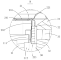
本実施形態では、図5に示すように、前記振動膜21には、それを振動方向に沿って貫通する第1貫通孔211が設置され、前記振動膜21は、前記第1貫通孔211を取り囲むように形成される内縁212と、前記フレーム1に固定された前記第3固定部13の外縁213と、前記内縁212と前記外縁213との間に設置された中間部214とを備える。ここで、前記内縁212は、前記第1磁性鋼32に固定され、前記MEMSスピーカ4は、前記第1貫通孔211を通って前記第2磁性鋼34に固定され、具体的には、前記MEMSスピーカ4は、前記第2磁性鋼34の前記磁気ヨーク31から離れる面に固定される。
In this embodiment, as shown in FIG. 5, the
また、前記フレーム1と前記磁気ヨーク31との間をよりよく固定するために、前記磁気ヨーク31の前記側壁312には、それを振動方向に垂直な方向に沿って貫通する第3貫通孔314が設置され、前記第1固定部11には、前記第3貫通孔314内に挿設されかつ前記側壁312に固定された凸出部111が設置され、前記凸出部111を設置することにより、前記第1固定部11と前記側壁312との間の固定面積を増加させ、結合強度を効果的に向上させることができる。
In addition, in order to better fix the
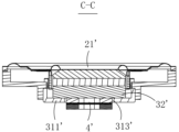
図7~図9に示すように、本発明の他の実施形態で提供されるイヤホンコア200では、前記磁気ヨーク31’の前記底壁311’にはそれを振動方向に沿って貫通する第2貫通孔313’が設置され、前記第1磁性鋼32’が前記底壁311’に固定されかつ前記第2貫通孔313’を覆い、前記MEMSスピーカ4’が前記第2貫通孔313’を通って前記第1磁性鋼32’に固定され、具体的には、本実施形態では、前記MEMSスピーカ4’が、前記第1磁性鋼32’の前記振動膜21’から離れる面に固定される。
As shown in Figures 7 to 9, in the
なお、本発明では、前記MEMSスピーカ4の具体的な構造は、具体的に限定されず、高音周波数帯域の音響効果を発することができるMEMSスピーカであればよい。
In the present invention, the specific structure of the
関連技術に比べて、本発明によるイヤホンコアは、フレーム及び前記フレームに固定された振動システムと磁気回路システムを備え、前記振動システムは、前記フレームに固定された振動膜と、前記振動膜の前記磁気回路システムに向かう側に固定されたボイスコイルとを備え、前記磁気回路システムは、前記フレームに固定された磁気ヨーク及び前記磁気ヨークに固定された第1磁性鋼を備え、前記イヤホンコアは、振動方向に沿って前記第1磁性鋼に固定された高音MEMSスピーカをさらに備え、前記MEMSスピーカ、前記ボイスコイル及び前記振動膜は、振動方向に沿って同軸に設置される。前記振動システム及び前記磁気回路システムは、低音と中音効果を提供することに用いられ、前記MEMSスピーカは、高音効果を提供することによって、同軸高中低音組合せの軸方向の高さを効果的に低減することができる。 Compared to the related art, the earphone core according to the present invention comprises a frame, a vibration system fixed to the frame, and a magnetic circuit system, the vibration system comprises a diaphragm fixed to the frame and a voice coil fixed to the side of the diaphragm facing the magnetic circuit system, the magnetic circuit system comprises a magnetic yoke fixed to the frame and a first magnetic steel fixed to the magnetic yoke, the earphone core further comprises a treble MEMS speaker fixed to the first magnetic steel along the vibration direction, and the MEMS speaker, the voice coil, and the diaphragm are coaxially installed along the vibration direction. The vibration system and the magnetic circuit system are used to provide bass and midrange effects, and the MEMS speaker provides a treble effect, thereby effectively reducing the axial height of the coaxial treble-midrange-bass combination.
上記したのは、本発明の実施形態だけであり、本発明が属する技術分野の当業者にとって、本発明の創造的構想から逸脱することなく、更に改善することができるが、これらはいずれも本発明の保護範囲内に属するものと理解されるべきである。
The above is only an embodiment of the present invention, and those skilled in the art to which the present invention pertains may further improve it without departing from the creative concept of the present invention, but it should be understood that all of these fall within the scope of protection of the present invention.
Claims (7)
収容スペースを有するフレームと、前記フレームに固定された振動システム及び磁気ギャップを有する磁気回路システムとを備え、
前記振動システムは、前記フレームに固定された環状の振動膜と、前記振動膜の前記磁気回路システムに向かう側に固定されたボイスコイルとを備え、
前記ボイスコイルは、前記磁気ギャップに挿設され、
前記磁気回路システムは、前記フレームに固定された磁気ヨークと、前記磁気ヨークに固定された第1磁性鋼とを備え、
前記イヤホンコアは、振動方向に沿って前記第1磁性鋼に固定された高音MEMSスピーカをさらに備え、
前記MEMSスピーカ、前記ボイスコイル及び前記振動膜は、振動方向に沿って同軸に設置され、
前記振動システムは、前記振動膜に固定されかつ前記ボイスコイルを前記磁気ギャップ内に支持するボイスコイルボビンを備え、前記ボイスコイルボビンは、前記振動膜の前記ボイスコイルに向かう側に固定された第1支持部と、前記第1支持部から前記磁気ギャップ内に向かって折り曲げて延在する第2支持部と、前記第2支持部の前記振動膜から離れる一端から前記第1磁性鋼に向かって折り曲げて延在する第3支持部とを備え、前記ボイスコイルは、前記第3支持部の前記振動膜に向かう面に担持され、かつ前記第2支持部の前記第1磁性鋼に向かう面に貼り付けられ、
前記磁気ヨークは、前記第1磁性鋼に固定された底壁と、前記底壁のエッジから前記振動膜に向かって折り曲げて延在する側壁とを備え、前記側壁と前記第1磁性鋼とによって取り囲んで前記磁気ギャップが形成され、
前記フレームは、前記側壁に周回固定された第1固定部と、前記第1固定部のエッジから前記ボイスコイルから離れる方向に折り曲げて延在する第2固定部と、前記第2固定部の前記第1固定部から離れたエッジから前記振動膜に向かって折り曲げて延在する第3固定部とを備え、前記振動膜は、前記第3固定部に固定され、
前記振動システムは、前記振動膜に固定されたFPCをさらに備え、前記FPCは、前記振動膜に固定された第1接続部と、前記第3固定部に固定された第2接続部と、前記第1接続部と前記第2接続部とを接続する、間隔をあけて設置された複数の弾性部とを備え、前記第1接続部は、前記第1支持部の前記振動膜から離れる面に固定される、ことを特徴とするイヤホンコア。 An earphone core,
A magnetic circuit system having a magnetic gap and a vibration system fixed to the frame,
the vibration system includes an annular diaphragm fixed to the frame, and a voice coil fixed to a side of the diaphragm facing the magnetic circuit system,
The voice coil is inserted into the magnetic gap,
the magnetic circuit system includes a magnetic yoke fixed to the frame and a first magnetic steel fixed to the magnetic yoke;
The earphone core further includes a high-frequency MEMS speaker fixed to the first magnetic steel along a vibration direction;
The MEMS speaker, the voice coil, and the diaphragm are coaxially arranged along a vibration direction ,
the vibration system includes a voice coil bobbin fixed to the vibration membrane and supporting the voice coil in the magnetic gap, the voice coil bobbin including a first support portion fixed to a side of the vibration membrane facing the voice coil, a second support portion bending and extending from the first support portion toward the magnetic gap, and a third support portion bending and extending from one end of the second support portion away from the vibration membrane toward the first magnetic steel, the voice coil being supported on a surface of the third support portion facing the vibration membrane and affixed to a surface of the second support portion facing the first magnetic steel,
the magnetic yoke includes a bottom wall fixed to the first magnetic steel and a side wall extending from an edge of the bottom wall toward the vibration membrane, the side wall and the first magnetic steel surrounding the magnetic gap form the magnetic gap,
the frame includes a first fixing portion circumferentially fixed to the side wall, a second fixing portion bent and extending from an edge of the first fixing portion in a direction away from the voice coil, and a third fixing portion bent and extending from an edge of the second fixing portion away from the first fixing portion toward the diaphragm, the diaphragm being fixed to the third fixing portion,
The vibration system further includes an FPC fixed to the vibration membrane, the FPC including a first connection portion fixed to the vibration membrane, a second connection portion fixed to the third fixed portion, and a plurality of elastic portions installed at intervals and connecting the first connection portion and the second connection portion, the first connection portion being fixed to a surface of the first support portion away from the vibration membrane .
Applications Claiming Priority (3)
| Application Number | Priority Date | Filing Date | Title |
|---|---|---|---|
| CN202221658267.6U CN217789879U (en) | 2022-06-29 | 2022-06-29 | Earphone core |
| CN202221658267.6 | 2022-06-29 | ||
| PCT/CN2022/107736 WO2024000707A1 (en) | 2022-06-29 | 2022-07-26 | Earphone core |
Publications (2)
| Publication Number | Publication Date |
|---|---|
| JP2024529201A JP2024529201A (en) | 2024-08-06 |
| JP7574331B2 true JP7574331B2 (en) | 2024-10-28 |
Family
ID=83937361
Family Applications (1)
| Application Number | Title | Priority Date | Filing Date |
|---|---|---|---|
| JP2022578983A Active JP7574331B2 (en) | 2022-06-29 | 2022-07-26 | Earphone Core |
Country Status (4)
| Country | Link |
|---|---|
| US (1) | US20250150750A1 (en) |
| JP (1) | JP7574331B2 (en) |
| CN (1) | CN217789879U (en) |
| WO (1) | WO2024000707A1 (en) |
Families Citing this family (1)
| Publication number | Priority date | Publication date | Assignee | Title |
|---|---|---|---|---|
| WO2025016177A1 (en) * | 2023-07-19 | 2025-01-23 | 刘垣皜 | Loudspeaker and earphone |
Citations (4)
| Publication number | Priority date | Publication date | Assignee | Title |
|---|---|---|---|---|
| JP2001359193A (en) | 2000-06-16 | 2001-12-26 | Namiki Precision Jewel Co Ltd | Mounting structure of diaphragm and voice coil for electromagnetic induction type actuator |
| JP2003179995A (en) | 2001-12-10 | 2003-06-27 | Kenwood Corp | Magnetic circuit for speaker |
| JP2004364101A (en) | 2003-06-06 | 2004-12-24 | Matsushita Electric Ind Co Ltd | Speaker and mobile phone device using the same |
| CN114598973A (en) | 2020-12-07 | 2022-06-07 | 华为技术有限公司 | A loudspeaker and electronic equipment |
Family Cites Families (5)
| Publication number | Priority date | Publication date | Assignee | Title |
|---|---|---|---|---|
| JPS5734691U (en) * | 1980-07-30 | 1982-02-23 | ||
| JP3641819B2 (en) * | 1998-03-05 | 2005-04-27 | アツデン株式会社 | Electric / acoustic transducer |
| KR101877176B1 (en) * | 2017-06-22 | 2018-07-10 | 유수호 | Hybrid speaker |
| CN114390407A (en) * | 2022-01-25 | 2022-04-22 | 瑞声光电科技(常州)有限公司 | Coaxial loudspeaker |
| CN114650489A (en) * | 2022-03-10 | 2022-06-21 | 歌尔股份有限公司 | Speakers and Sound Equipment |
-
2022
- 2022-06-29 CN CN202221658267.6U patent/CN217789879U/en not_active Expired - Fee Related
- 2022-07-26 US US17/913,825 patent/US20250150750A1/en active Pending
- 2022-07-26 WO PCT/CN2022/107736 patent/WO2024000707A1/en not_active Ceased
- 2022-07-26 JP JP2022578983A patent/JP7574331B2/en active Active
Patent Citations (4)
| Publication number | Priority date | Publication date | Assignee | Title |
|---|---|---|---|---|
| JP2001359193A (en) | 2000-06-16 | 2001-12-26 | Namiki Precision Jewel Co Ltd | Mounting structure of diaphragm and voice coil for electromagnetic induction type actuator |
| JP2003179995A (en) | 2001-12-10 | 2003-06-27 | Kenwood Corp | Magnetic circuit for speaker |
| JP2004364101A (en) | 2003-06-06 | 2004-12-24 | Matsushita Electric Ind Co Ltd | Speaker and mobile phone device using the same |
| CN114598973A (en) | 2020-12-07 | 2022-06-07 | 华为技术有限公司 | A loudspeaker and electronic equipment |
Also Published As
| Publication number | Publication date |
|---|---|
| JP2024529201A (en) | 2024-08-06 |
| WO2024000707A1 (en) | 2024-01-04 |
| US20250150750A1 (en) | 2025-05-08 |
| CN217789879U (en) | 2022-11-11 |
Similar Documents
| Publication | Publication Date | Title |
|---|---|---|
| CN115396795B (en) | Sound producing device and electronic equipment | |
| JP4237702B2 (en) | Dynamic microspeaker with dual suspension | |
| JP7662675B2 (en) | Coaxial Speaker | |
| CN218473384U (en) | Coaxial loudspeaker | |
| WO2022062039A1 (en) | Sound-producing unit and electronic terminal | |
| US12289590B2 (en) | Coaxial speaker | |
| JP7634334B2 (en) | Coaxial Speaker | |
| JP7553610B2 (en) | Coaxial Speaker Box | |
| JP6363792B2 (en) | Electroacoustic transducer | |
| WO2024044924A1 (en) | Coaxial loudspeaker | |
| JP7591064B2 (en) | Coaxial Speaker | |
| JP7574331B2 (en) | Earphone Core | |
| CN108834032A (en) | loudspeaker and earphone | |
| KR20110102182A (en) | Speaker | |
| CN115314815A (en) | A speaker unit and electronic equipment | |
| CN218473381U (en) | Coaxial loudspeaker | |
| JP6176096B2 (en) | Headphone device | |
| JP7637704B2 (en) | speaker | |
| KR100676422B1 (en) | Multi-point driven multiway slim flat speaker system | |
| CN115412811B (en) | Sound-generating device and electronic equipment | |
| KR20110110685A (en) | Hi-Fi Speaker Unit for Earphones | |
| WO2024044923A1 (en) | Coaxial loudspeaker | |
| CN221688835U (en) | Double-loudspeaker | |
| CN221381177U (en) | A coaxial linear speaker structure | |
| US12207072B2 (en) | Speaker |
Legal Events
| Date | Code | Title | Description |
|---|---|---|---|
| A621 | Written request for application examination |
Free format text: JAPANESE INTERMEDIATE CODE: A621 Effective date: 20230524 |
|
| A871 | Explanation of circumstances concerning accelerated examination |
Free format text: JAPANESE INTERMEDIATE CODE: A871 Effective date: 20230809 |
|
| A131 | Notification of reasons for refusal |
Free format text: JAPANESE INTERMEDIATE CODE: A131 Effective date: 20240612 |
|
| A521 | Request for written amendment filed |
Free format text: JAPANESE INTERMEDIATE CODE: A523 Effective date: 20240910 |
|
| TRDD | Decision of grant or rejection written | ||
| A01 | Written decision to grant a patent or to grant a registration (utility model) |
Free format text: JAPANESE INTERMEDIATE CODE: A01 Effective date: 20241015 |
|
| A61 | First payment of annual fees (during grant procedure) |
Free format text: JAPANESE INTERMEDIATE CODE: A61 Effective date: 20241016 |
|
| R150 | Certificate of patent or registration of utility model |
Ref document number: 7574331 Country of ref document: JP Free format text: JAPANESE INTERMEDIATE CODE: R150 |