JP7572909B2 - Power storage device - Google Patents

Power storage device Download PDF

Info

Publication number
JP7572909B2
JP7572909B2 JP2021082545A JP2021082545A JP7572909B2 JP 7572909 B2 JP7572909 B2 JP 7572909B2 JP 2021082545 A JP2021082545 A JP 2021082545A JP 2021082545 A JP2021082545 A JP 2021082545A JP 7572909 B2 JP7572909 B2 JP 7572909B2
Authority
JP
Japan
Prior art keywords
plate
stack
recess
module stack
electrode
Prior art date
Legal status (The legal status is an assumption and is not a legal conclusion. Google has not performed a legal analysis and makes no representation as to the accuracy of the status listed.)
Active
Application number
JP2021082545A
Other languages
Japanese (ja)
Other versions
JP2022175827A (en
Inventor
昭人 柘植
直人 守作
浩生 植田
滋 福田
怜史 森岡
素宜 奥村
Current Assignee (The listed assignees may be inaccurate. Google has not performed a legal analysis and makes no representation or warranty as to the accuracy of the list.)
Toyota Industries Corp
Toyota Motor Corp
Original Assignee
Toyota Industries Corp
Toyota Motor Corp
Priority date (The priority date is an assumption and is not a legal conclusion. Google has not performed a legal analysis and makes no representation as to the accuracy of the date listed.)
Filing date
Publication date
Application filed by Toyota Industries Corp, Toyota Motor Corp filed Critical Toyota Industries Corp
Priority to JP2021082545A priority Critical patent/JP7572909B2/en
Publication of JP2022175827A publication Critical patent/JP2022175827A/en
Application granted granted Critical
Publication of JP7572909B2 publication Critical patent/JP7572909B2/en
Active legal-status Critical Current
Anticipated expiration legal-status Critical

Links

Images

Classifications

    • YGENERAL TAGGING OF NEW TECHNOLOGICAL DEVELOPMENTS; GENERAL TAGGING OF CROSS-SECTIONAL TECHNOLOGIES SPANNING OVER SEVERAL SECTIONS OF THE IPC; TECHNICAL SUBJECTS COVERED BY FORMER USPC CROSS-REFERENCE ART COLLECTIONS [XRACs] AND DIGESTS
    • Y02TECHNOLOGIES OR APPLICATIONS FOR MITIGATION OR ADAPTATION AGAINST CLIMATE CHANGE
    • Y02EREDUCTION OF GREENHOUSE GAS [GHG] EMISSIONS, RELATED TO ENERGY GENERATION, TRANSMISSION OR DISTRIBUTION
    • Y02E60/00Enabling technologies; Technologies with a potential or indirect contribution to GHG emissions mitigation
    • Y02E60/10Energy storage using batteries

Landscapes

  • Electric Double-Layer Capacitors Or The Like (AREA)
  • Sealing Battery Cases Or Jackets (AREA)
  • Secondary Cells (AREA)
  • Battery Mounting, Suspending (AREA)

Description

本開示は、蓄電装置に関する。 This disclosure relates to an electricity storage device.

積層された複数の蓄電モジュールを有する積層体と、積層体の積層端と対向する内面を有し、積層体に積層方向の拘束荷重を付加する拘束板と、を備える蓄電装置が知られている(特許文献1参照)。 A known energy storage device includes a stack having multiple stacked energy storage modules, and a restraining plate that has an inner surface facing the stacking end of the stack and applies a restraining load to the stack in the stacking direction (see Patent Document 1).

特開2010-157450号公報JP 2010-157450 A

上記蓄電装置では、周辺環境の急激な温度及び湿度の変化により、積層体の表面に水滴が付着する場合がある。また、上記蓄電装置では、拘束板に肉盗み部として凹部が設けられる場合がある。拘束板の内面に設けられた凹部に水滴が溜まり、凹部の側壁を超えて積層体側に侵入することにより、積層された蓄電モジュール間で短絡(トラッキング)が生じるおそれがある。 In the above-mentioned energy storage device, sudden changes in temperature and humidity in the surrounding environment may cause water droplets to adhere to the surface of the stack. Also, in the above-mentioned energy storage device, a recess may be provided in the restraining plate as a material-removing portion. Water droplets may accumulate in the recess provided on the inner surface of the restraining plate and may pass over the side wall of the recess and enter the stack, causing a short circuit (tracking) between the stacked energy storage modules.

本開示の目的は、蓄電モジュール間で短絡が生じることを抑制可能な蓄電装置の提供である。 The purpose of this disclosure is to provide an energy storage device that can prevent short circuits from occurring between energy storage modules.

本開示の一側面に係る蓄電装置は、第1方向において積層された複数の蓄電モジュールを有するモジュール積層体と、第1方向においてモジュール積層体上に積層された絶縁板と、第1方向において絶縁板上に積層され、モジュール積層体及び絶縁板に拘束荷重を付加する拘束板と、を備え、拘束板は、モジュール積層体の重力方向の下側に配置され、第1方向から見てモジュール積層体と重なる本体部と、第1方向から見てモジュール積層体と隣り合う縁部と、を有し、縁部は、第1方向の内側に開口する凹部を有し、凹部は、第1方向に直交する第2方向でモジュール積層体と対向する側壁を有し、絶縁板は、モジュール積層体と本体部との間に配置された底部と、モジュール積層体と側壁との間に配置された側部と、を有し、側部の第1方向における高さは、側壁の第1方向における高さ以上であり、凹部には、液体排出口が設けられている。 The energy storage device according to one aspect of the present disclosure includes a module stack having a plurality of energy storage modules stacked in a first direction, an insulating plate stacked on the module stack in the first direction, and a restraining plate stacked on the insulating plate in the first direction and applying a restraining load to the module stack and the insulating plate, the restraining plate is disposed below the module stack in the gravity direction and has a main body portion overlapping the module stack when viewed from the first direction and an edge portion adjacent to the module stack when viewed from the first direction, the edge portion has a recess that opens to the inside in the first direction, the recess has a side wall facing the module stack in a second direction perpendicular to the first direction, the insulating plate has a bottom portion disposed between the module stack and the main body portion and a side portion disposed between the module stack and the side wall, the height of the side portion in the first direction is equal to or greater than the height of the side wall in the first direction, and the recess is provided with a liquid outlet.

上記蓄電装置では、拘束板の縁部は、第1方向の内側(重力方向の上側)に開口する凹部を有している。凹部には液体排出口が設けられているので、凹部に水滴が溜まることが抑制される。モジュール積層体と拘束板の間に配置された絶縁板は、モジュール積層体と拘束板の本体部との間に配置された底部だけでなく、モジュール積層体と凹部の側壁との間に配置された側部を有している。側部の第1方向における高さは、側壁の第1方向における高さ以上である。このため、仮に凹部に水滴が溜まったとしても、凹部の側壁を超えてモジュール積層体側に侵入することが絶縁板によって抑制される。以上により、蓄電モジュール間で短絡が生じることが抑制される。 In the above-mentioned energy storage device, the edge of the restraining plate has a recess that opens to the inside in the first direction (upward in the direction of gravity). A liquid outlet is provided in the recess, which prevents water droplets from accumulating in the recess. The insulating plate arranged between the module stack and the restraining plate has not only a bottom portion arranged between the module stack and the main body of the restraining plate, but also a side portion arranged between the module stack and the side wall of the recess. The height of the side portion in the first direction is equal to or greater than the height of the side wall in the first direction. Therefore, even if water droplets accumulate in the recess, the insulating plate prevents the water droplets from crossing the side wall of the recess and entering the module stack. As a result, the occurrence of a short circuit between the energy storage modules is prevented.

モジュール積層体は、隣り合う蓄電モジュール間に設けられた集電板を有し、集電板には、第1方向に直交する第2方向に延在し、冷却用流体が流入する入口と、冷却用流体が流出する出口と、を有する流路が設けられており、凹部は、第1方向から見て、出口と隣り合うように設けられていてもよい。この場合、水滴が冷却用流体により出口から飛ばされ、凹部に溜まり易い。よって、液体排出口及び絶縁板の構成がより有効である。 The module stack has current collector plates provided between adjacent storage modules, and the current collector plates are provided with flow paths extending in a second direction perpendicular to the first direction and having an inlet through which the cooling fluid flows and an outlet through which the cooling fluid flows out, and the recesses may be provided adjacent to the outlets when viewed from the first direction. In this case, water droplets are easily blown away from the outlet by the cooling fluid and accumulate in the recesses. Therefore, the configuration of the liquid outlet and insulating plate is more effective.

流路は、第1方向と第2方向とに直交する第3方向に沿って複数配列されており、凹部は、第1方向から見て、複数の出口と隣り合うように第3方向に沿って延在していてもよい。この場合、凹部には、水滴が更に溜まり易い。よって、液体排出口及び絶縁板の構成がより一層有効である。 The flow paths may be arranged in a third direction perpendicular to the first and second directions, and the recess may extend along the third direction so as to be adjacent to the outlets when viewed from the first direction. In this case, water droplets are more likely to accumulate in the recess. Therefore, the configuration of the liquid outlet and the insulating plate is even more effective.

複数の蓄電モジュールのそれぞれは、セパレータを介して第1方向において積層された複数の電極を含む電極積層体と、電極積層体の第1方向に沿う側面を取り囲むとともに、隣り合う電極間に形成された内部空間を封止する封止体と、を有し、封止体は、第1方向に沿う外周面と、外周面に設けられ、電極積層体の外側に向けて張り出す庇部と、を有してもよい。この場合、凹部には、庇部によって水滴が更に溜まり易い。よって、液体排出口及び絶縁板の構成がより有効である。 Each of the multiple storage modules has an electrode stack including multiple electrodes stacked in a first direction via separators, and a sealing body that surrounds the side of the electrode stack along the first direction and seals the internal space formed between adjacent electrodes, and the sealing body may have an outer peripheral surface along the first direction and an overhanging portion provided on the outer peripheral surface and extending outward toward the outside of the electrode stack. In this case, the overhanging portion makes it even easier for water droplets to accumulate in the recess. Therefore, the configuration of the liquid outlet and insulating plate is more effective.

液体排出口は、凹部の底壁を第1方向において貫通する貫通孔であってもよい。この場合、液体排出口が凹部の側壁に設けられている場合に比べて、凹部に水滴が溜まり難い。 The liquid outlet may be a through-hole that penetrates the bottom wall of the recess in the first direction. In this case, water droplets are less likely to accumulate in the recess compared to when the liquid outlet is provided in the side wall of the recess.

本開示によれば、蓄電モジュール間で短絡が生じることを抑制可能な蓄電装置が提供される。 According to the present disclosure, a power storage device is provided that can prevent short circuits from occurring between power storage modules.

図1は、一実施形態に係る蓄電装置の斜視図である。FIG. 1 is a perspective view of an electricity storage device according to an embodiment. 図2は、図1のII-II線に沿った断面図である。FIG. 2 is a cross-sectional view taken along line II-II of FIG. 図3は、図1のIII-III線に沿った断面図である。FIG. 3 is a cross-sectional view taken along line III-III in FIG. 図4は、図1のIV-IV線に沿った断面図である。FIG. 4 is a cross-sectional view taken along line IV-IV in FIG. 図5は、図1に示される蓄電モジュールの内部構成を示す概略断面図である。FIG. 5 is a schematic cross-sectional view showing the internal configuration of the power storage module shown in FIG. 図6は、図1に示される蓄電モジュールの斜視図である。FIG. 6 is a perspective view of the power storage module shown in FIG. 図7は、図1に示される拘束板の内面を示す平面図である。7 is a plan view showing the inner surface of the restraining plate shown in FIG. 1. FIG. 図8は、図1に示される蓄電装置の一部拡大断面図である。FIG. 8 is a partially enlarged cross-sectional view of the power storage device shown in FIG.

以下、添付図面を参照しながら本発明の実施形態が詳細に説明される。図面の説明において、同一又は同等の要素には同一符号が用いられ、重複する説明は省略される。 Embodiments of the present invention will now be described in detail with reference to the accompanying drawings. In the description of the drawings, the same or equivalent elements are designated by the same reference numerals, and duplicate descriptions will be omitted.

図1~図8を参照して、本実施形態に係る蓄電装置1について説明する。図1に示される蓄電装置1は、例えば、フォークリフト、ハイブリッド自動車、電気自動車等の各種車両のバッテリに用いられる。蓄電装置1は、例えばニッケル水素二次電池又はリチウムイオン二次電池等の二次電池である。蓄電装置1は、例えば電気二重層キャパシタであってもよい。本実施形態では、蓄電装置1がニッケル水素電池である場合を例示する。 The energy storage device 1 according to this embodiment will be described with reference to Figures 1 to 8. The energy storage device 1 shown in Figure 1 is used as a battery for various vehicles such as a forklift, a hybrid vehicle, and an electric vehicle. The energy storage device 1 is, for example, a secondary battery such as a nickel-metal hydride secondary battery or a lithium-ion secondary battery. The energy storage device 1 may also be, for example, an electric double layer capacitor. In this embodiment, the case where the energy storage device 1 is a nickel-metal hydride battery is illustrated.

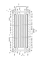
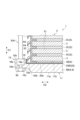
図1及び図2に示されるように、蓄電装置1は、モジュール積層体2と、拘束部材4と、一対の絶縁板20と、ダクト21と、を備えている。モジュール積層体2は、第1方向D1において積層された複数(本実施形態では7つ)の蓄電モジュール3と、複数(本実施形態では8つ)の集電板5と、を含んでいる。第1方向D1は、例えば、重力方向である。 As shown in Figs. 1 and 2, the energy storage device 1 includes a module stack 2, a restraining member 4, a pair of insulating plates 20, and a duct 21. The module stack 2 includes a plurality of (seven in this embodiment) energy storage modules 3 stacked in a first direction D1, and a plurality of (eight in this embodiment) current collector plates 5. The first direction D1 is, for example, the direction of gravity.

複数の蓄電モジュール3は、集電板5を介して第1方向D1において積層されている。複数の蓄電モジュール3は、集電板5を介して第1方向D1において電気的に直列に接続されている。集電板5は、例えば金属等の導電材料からなる板状部材である。集電板5の材料としては、例えばアルミニウムが挙げられる。集電板5の表面には、例えばニッケル等のめっき層が形成されていてもよい。本実施形態では、第1方向D1から見た集電板5の面積は、蓄電モジュール3の面積よりも小さい。 The multiple storage modules 3 are stacked in the first direction D1 via the current collector plates 5. The multiple storage modules 3 are electrically connected in series in the first direction D1 via the current collector plates 5. The current collector plates 5 are plate-shaped members made of a conductive material such as a metal. Examples of materials for the current collector plates 5 include aluminum. A plating layer of nickel or the like may be formed on the surface of the current collector plates 5. In this embodiment, the area of the current collector plates 5 as viewed from the first direction D1 is smaller than the area of the storage modules 3.

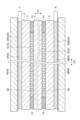
図2に示されるように、複数の集電板5は、第1方向D1における一端側の集電板5Aと、他端側の集電板5Bと、蓄電モジュール3間に介在する複数(本実施形態では6つ)の集電板5Cと、を含んでいる。集電板5Cは、第1方向D1において互いに隣り合う蓄電モジュール3間に設けられ、複数の蓄電モジュール3と電気的に接続されている。第1方向D1において互いに隣り合う蓄電モジュール3間において、集電板5Cは、後述する金属板60Bの他方面60bの露出部60d、及び、金属板60Aの一方面60aの露出部60dのそれぞれに接触配置されている。 2, the multiple current collectors 5 include a current collector 5A at one end in the first direction D1, a current collector 5B at the other end, and multiple (six in this embodiment) current collectors 5C interposed between the power storage modules 3. The current collectors 5C are provided between the power storage modules 3 adjacent to each other in the first direction D1 and are electrically connected to the multiple power storage modules 3. Between the power storage modules 3 adjacent to each other in the first direction D1, the current collectors 5C are arranged in contact with the exposed portion 60d of the other surface 60b of the metal plate 60B described later and the exposed portion 60d of the one surface 60a of the metal plate 60A.

集電板5A,5Bは、複数の蓄電モジュール3及び複数の集電板5Cを第1方向D1の両側から挟むように配置されている。集電板5A,5Bは、第1方向D1において、積層端に位置する蓄電モジュール3上にそれぞれ積層されている。集電板5Aは、第1方向D1において、一方の積層端に位置する蓄電モジュール3上に積層され、少なくとも当該蓄電モジュール3と電気的に接続されている。集電板5Bは、第1方向D1において、他方の積層端に位置する蓄電モジュール3上に積層され、少なくとも当該蓄電モジュール3と電気的に接続されている。 The current collectors 5A and 5B are arranged to sandwich the multiple storage modules 3 and the multiple current collectors 5C from both sides in the first direction D1. The current collectors 5A and 5B are each stacked on the storage modules 3 located at the stacking ends in the first direction D1. The current collector 5A is stacked on the storage module 3 located at one stacking end in the first direction D1 and is electrically connected to at least the storage module 3. The current collector 5B is stacked on the storage module 3 located at the other stacking end in the first direction D1 and is electrically connected to at least the storage module 3.

集電板5Aには、負極端子7(図1参照)が接続されている。負極端子7は、集電板5Aの縁部から、第1方向D1及び第2方向D2に直交する第3方向D3に引き出されている。集電板5Bには、正極端子6(図1参照)が接続されている。正極端子6は、集電板5Bの縁部から第3方向D3に引き出されている。正極端子6及び負極端子7により、蓄電装置1の充放電が実施される。本実施形態では、集電板5Bは、集電板5Aよりも重力方向の下側に配置されている。 A negative electrode terminal 7 (see FIG. 1) is connected to the current collector 5A. The negative electrode terminal 7 is drawn from an edge of the current collector 5A in a third direction D3 perpendicular to the first direction D1 and the second direction D2. A positive electrode terminal 6 (see FIG. 1) is connected to the current collector 5B. The positive electrode terminal 6 is drawn from an edge of the current collector 5B in the third direction D3. The positive electrode terminal 6 and the negative electrode terminal 7 are used to charge and discharge the energy storage device 1. In this embodiment, the current collector 5B is disposed lower in the direction of gravity than the current collector 5A.

図3及び図4に示されるように、集電板5Cには、冷却用流体を流通させる複数の流路5aが設けられている。ここで、冷却用流体としては、例えば、空気、水等が用いられる。流路5aは、第1方向D1に直交する第2方向D2に沿って延在する貫通孔である。流路5aは、冷却用流体が流入する入口5bと、冷却用流体が流出する出口5cとを有している。流路5aは、第3方向D3に沿って複数配列されている。複数の集電板5Cは、流路5aに冷却用流体を流通させることにより、蓄電モジュール3で発生した熱を放熱する放熱板として機能する。集電板5A,5Bには、流路は設けられていない。 As shown in Figs. 3 and 4, the current collector plate 5C is provided with a plurality of flow paths 5a for circulating the cooling fluid. Here, the cooling fluid may be, for example, air or water. The flow paths 5a are through holes extending along a second direction D2 perpendicular to the first direction D1. The flow paths 5a have an inlet 5b through which the cooling fluid flows in and an outlet 5c through which the cooling fluid flows out. A plurality of flow paths 5a are arranged along a third direction D3. The plurality of current collector plates 5C function as heat sinks that radiate heat generated in the power storage module 3 by circulating the cooling fluid through the flow paths 5a. No flow paths are provided in the current collector plates 5A and 5B.

モジュール積層体2は、集電板5Cの第3方向D3の両側に配置された複数の検出素子12を有している。検出素子12は、集電板5Cと共に、第1方向D1において互いに隣り合う蓄電モジュール3間に設けられている。検出素子12は、例えば、蓄電モジュール3の温度を検出する素子、及び蓄電モジュール3から出力される電圧を検出する素子を含み、蓄電モジュール3の状態を監視するセンサである。検出素子12は、例えば、ポリプロピレン(PP)のような耐アルカリ性を有する絶縁性の樹脂により、集電板5と同じ厚さで形成されている。検出素子12は、集電板5Cの第3方向D3の両端部に連結されている。 The module stack 2 has a plurality of detection elements 12 arranged on both sides of the current collector 5C in the third direction D3. The detection elements 12 are provided, together with the current collector 5C, between adjacent storage modules 3 in the first direction D1. The detection elements 12 are sensors that monitor the state of the storage modules 3, and include, for example, an element that detects the temperature of the storage module 3 and an element that detects the voltage output from the storage module 3. The detection elements 12 are formed with the same thickness as the current collector 5, for example, from an insulating resin having alkali resistance such as polypropylene (PP). The detection elements 12 are connected to both ends of the current collector 5C in the third direction D3.

ダクト21は、各流路5aの入口5bに冷却用流体を流入させるように構成されている。ダクト21は、集電板5Cの入口5bが設けられた側面に対向し、第3方向D3に延びている。ダクト21の第3方向D3における一端は開放され、ダクト21に冷却用流体を導入する入口21aを構成している。ダクト21の第3方向D3における他端は、閉塞されている。入口21aからダクト21に流入した冷却用流体は、ダクト21を流通し、流路5aの入口5bへと導かれる。入口5bから流路5aに流入した冷却用流体は、流路5aを流通し、出口5cから流出する。 The duct 21 is configured to allow the cooling fluid to flow into the inlet 5b of each flow path 5a. The duct 21 faces the side of the current collector 5C on which the inlet 5b is provided, and extends in the third direction D3. One end of the duct 21 in the third direction D3 is open, and forms an inlet 21a that introduces the cooling fluid into the duct 21. The other end of the duct 21 in the third direction D3 is closed. The cooling fluid that flows into the duct 21 from the inlet 21a flows through the duct 21 and is guided to the inlet 5b of the flow path 5a. The cooling fluid that flows into the flow path 5a from the inlet 5b flows through the flow path 5a and flows out from the outlet 5c.

図1に示されるように、ダクト21は、延在部21bを有する。延在部21bは、後述する縁部10の外面10aと対向するように、第2方向D2に沿って延在している。延在部21bは、後述の係合部分14と干渉しない形状及び大きさに形成されている。延在部21bには、固定ネジ19が挿通される貫通孔が形成されている。固定ネジ19は、当該貫通孔に挿通され、縁部10に設けられた穴部(不図示)に螺合されている。これにより、ダクト21は、拘束板8に固定されている。 As shown in FIG. 1, the duct 21 has an extension portion 21b. The extension portion 21b extends along the second direction D2 so as to face the outer surface 10a of the edge portion 10 described below. The extension portion 21b is formed in a shape and size that does not interfere with the engagement portion 14 described below. The extension portion 21b has a through hole through which a fixing screw 19 is inserted. The fixing screw 19 is inserted into the through hole and screwed into a hole (not shown) provided in the edge portion 10. In this way, the duct 21 is fixed to the restraining plate 8.

図5及び図6に示されるように、各蓄電モジュール3は、電極積層体51と、電極積層体51を封止する樹脂製の封止体52とを備えている。蓄電モジュール3は、例えば、直方体形状に形成されている。 As shown in Figs. 5 and 6, each storage module 3 includes an electrode stack 51 and a resin sealing body 52 that seals the electrode stack 51. The storage module 3 is formed, for example, in a rectangular parallelepiped shape.

電極積層体51は、セパレータ53を介して第1方向D1に積層された複数の電極と、金属板60A,60Bと、を含んでいる。複数の電極の積層体は、金属板60Aと金属板60Bとの間に設けられている。複数の電極は、複数のバイポーラ電極54の積層体と、負極終端電極58と、正極終端電極59とを含む。複数のバイポーラ電極54の積層体は、負極終端電極58及び正極終端電極59の間に設けられている。 The electrode stack 51 includes a plurality of electrodes stacked in the first direction D1 via a separator 53, and metal plates 60A and 60B. The stack of the plurality of electrodes is provided between the metal plates 60A and 60B. The plurality of electrodes includes a stack of a plurality of bipolar electrodes 54, a negative terminal electrode 58, and a positive terminal electrode 59. The stack of the plurality of bipolar electrodes 54 is provided between the negative terminal electrode 58 and the positive terminal electrode 59.

バイポーラ電極54は、一方面55a及び一方面55aの反対側の他方面55bを含む金属板55と、一方面55aに設けられた正極56と、他方面55bに設けられた負極57とを有している。正極56は、正極活物質が金属板55に塗工されることにより形成される正極活物質層である。負極57は、負極活物質が金属板55に塗工されることにより形成される負極活物質層である。電極積層体51において、一のバイポーラ電極54の正極56は、セパレータ53を挟んで第1方向D1の一方に隣り合う別のバイポーラ電極54の負極57と対向している。電極積層体51において、一のバイポーラ電極54の負極57は、セパレータ53を挟んで第1方向D1の他方に隣り合う別のバイポーラ電極54の正極56と対向している。 The bipolar electrode 54 has a metal plate 55 including one side 55a and the other side 55b opposite to the one side 55a, a positive electrode 56 provided on the one side 55a, and a negative electrode 57 provided on the other side 55b. The positive electrode 56 is a positive electrode active material layer formed by applying a positive electrode active material to the metal plate 55. The negative electrode 57 is a negative electrode active material layer formed by applying a negative electrode active material to the metal plate 55. In the electrode laminate 51, the positive electrode 56 of one bipolar electrode 54 faces the negative electrode 57 of another bipolar electrode 54 adjacent to the other side of the first direction D1 across the separator 53. In the electrode laminate 51, the negative electrode 57 of one bipolar electrode 54 faces the positive electrode 56 of another bipolar electrode 54 adjacent to the other side of the first direction D1 across the separator 53.

負極終端電極58は、金属板55と、金属板55の他方面55bに設けられた負極57とを有している。負極終端電極58は、他方面55bが電極積層体51における第1方向D1の中央側を向くように、第1方向D1の一端側に配置されている。負極終端電極58の金属板55の一方面55aには、金属板60Aが更に積層され、この金属板60Aを介して蓄電モジュール3に隣接する一方の集電板5(図2参照)と電気的に接続されている。負極終端電極58の金属板55の他方面55bに設けられた負極57は、セパレータ53を介して、第1方向D1の一端のバイポーラ電極54の正極56と対向している。 The negative terminal electrode 58 has a metal plate 55 and a negative electrode 57 provided on the other surface 55b of the metal plate 55. The negative terminal electrode 58 is arranged on one end side of the first direction D1 so that the other surface 55b faces the center side of the first direction D1 in the electrode laminate 51. A metal plate 60A is further laminated on one surface 55a of the metal plate 55 of the negative terminal electrode 58, and is electrically connected to one of the current collector plates 5 (see FIG. 2) adjacent to the storage module 3 via this metal plate 60A. The negative electrode 57 provided on the other surface 55b of the metal plate 55 of the negative terminal electrode 58 faces the positive electrode 56 of the bipolar electrode 54 at one end of the first direction D1 via the separator 53.

正極終端電極59は、金属板55と、金属板55の一方面55aに設けられた正極56とを有している。正極終端電極59は、一方面55aが電極積層体51における第1方向D1の中央側を向くように、第1方向D1の他端側に配置されている。正極終端電極59の金属板55の他方面55bには、金属板60Bが更に積層され、この金属板60Bを介して蓄電モジュール3に隣接する他方の集電板5(図2参照)と電気的に接続されている。正極終端電極59の金属板55の一方面55aに設けられた正極56は、セパレータ53を介して、第1方向D1の他端のバイポーラ電極54の負極57と対向している。 The positive terminal electrode 59 has a metal plate 55 and a positive electrode 56 provided on one side 55a of the metal plate 55. The positive terminal electrode 59 is arranged on the other end side of the first direction D1 so that the one side 55a faces the center side of the first direction D1 in the electrode stack 51. A metal plate 60B is further laminated on the other side 55b of the metal plate 55 of the positive terminal electrode 59, and is electrically connected to the other current collector plate 5 (see FIG. 2) adjacent to the storage module 3 via this metal plate 60B. The positive electrode 56 provided on one side 55a of the metal plate 55 of the positive terminal electrode 59 faces the negative electrode 57 of the bipolar electrode 54 at the other end of the first direction D1 via the separator 53.

金属板55は、例えば、ニッケル又はニッケルメッキ鋼板といった金属からなる。一例として、金属板55は、ニッケルからなる矩形の金属箔である。各金属板55は、いずれも電極積層体51に含まれる金属板の一つである。金属板55の縁部55cは、矩形枠状をなし、正極活物質及び負極活物質が塗工されない未塗工領域となっている。正極56を構成する正極活物質としては、例えば水酸化ニッケルが挙げられる。負極57を構成する負極活物質としては、例えば水素吸蔵合金が挙げられる。本実施形態では、金属板55の他方面55bにおける負極57の形成領域は、金属板55の一方面55aにおける正極56の形成領域に対して一回り大きくなっている。電極積層体51は、積層された複数の金属板55,60A,60Bを有している。 The metal plate 55 is made of a metal such as nickel or a nickel-plated steel plate. As an example, the metal plate 55 is a rectangular metal foil made of nickel. Each metal plate 55 is one of the metal plates included in the electrode stack 51. The edge portion 55c of the metal plate 55 has a rectangular frame shape and is an uncoated area where the positive electrode active material and the negative electrode active material are not coated. For example, nickel hydroxide is used as the positive electrode active material constituting the positive electrode 56. For example, a hydrogen storage alloy is used as the negative electrode active material constituting the negative electrode 57. In this embodiment, the formation area of the negative electrode 57 on the other surface 55b of the metal plate 55 is one size larger than the formation area of the positive electrode 56 on one surface 55a of the metal plate 55. The electrode stack 51 has a plurality of stacked metal plates 55, 60A, 60B.

セパレータ53は、金属板55同士の短絡を防止するための部材であり、例えばシート状に形成されている。セパレータ53としては、ポリエチレン(PE)、ポリプロピレン(PP)等のポリオレフィン系樹脂からなる多孔質フィルム、ポリプロピレン、メチルセルロース等からなる織布又は不織布等が例示される。セパレータ53は、フッ化ビニリデン樹脂化合物で補強されたものであってもよい。なお、セパレータ53は、シート状に限られず、袋状のものを用いてもよい。 The separator 53 is a member for preventing short circuits between the metal plates 55, and is formed, for example, in a sheet shape. Examples of the separator 53 include a porous film made of a polyolefin resin such as polyethylene (PE) or polypropylene (PP), and a woven or nonwoven fabric made of polypropylene, methylcellulose, or the like. The separator 53 may be reinforced with a vinylidene fluoride resin compound. The separator 53 is not limited to a sheet shape, and a bag-shaped one may also be used.

金属板60A,60Bは、金属板55と実質的に同一の部材であり、例えばニッケル又はニッケルメッキ鋼板といった金属からなる。金属板60A,60Bは、いずれも電極積層体51に含まれる金属板の一つである。一例として、金属板60A,60Bは、ニッケルからなる矩形の金属箔である。金属板60A,60Bは、一方面60a及び他方面60bに正極活物質層及び負極活物質層のいずれもが塗工されていない未塗工電極となっている。すなわち、金属板60A,60Bは、両面に活物質層が設けられていない未塗工電極である。 The metal plates 60A and 60B are substantially the same member as the metal plate 55, and are made of a metal such as nickel or nickel-plated steel. Both of the metal plates 60A and 60B are one of the metal plates included in the electrode stack 51. As an example, the metal plates 60A and 60B are rectangular metal foils made of nickel. The metal plates 60A and 60B are uncoated electrodes in which neither the positive electrode active material layer nor the negative electrode active material layer is coated on one side 60a nor the other side 60b. In other words, the metal plates 60A and 60B are uncoated electrodes in which no active material layer is provided on both sides.

金属板60Aは、電極積層体51の一方の積層端に位置している。金属板60Aにより、負極終端電極58は、第1方向D1に沿って金属板60Aとバイポーラ電極54との間に配置された状態となっている。金属板60Bは、電極積層体51の他方の積層端に位置している。金属板60Bにより、正極終端電極59は、第1方向D1に沿って金属板60Bとバイポーラ電極54との間に配置された状態となっている。電極積層体51では、電極積層体51の中央領域(バイポーラ電極54、負極終端電極58、及び正極終端電極59において活物質層が配置されている領域)が、その周りの領域に比べて第1方向D1に膨らんでいる。このため、金属板60A,60Bは、金属板60A,60Bの中央領域が互いに離間する方向に屈曲している。金属板60Aの一方面60a及び金属板60Bの他方面60bの中央領域は、集電板5と当接(接触)している。すなわち、集電板5は、電極積層体51の積層端の金属板60A,60Bに接触して配置されている。 The metal plate 60A is located at one end of the electrode stack 51. The metal plate 60A causes the negative terminal electrode 58 to be disposed between the metal plate 60A and the bipolar electrode 54 along the first direction D1. The metal plate 60B is located at the other end of the electrode stack 51. The metal plate 60B causes the positive terminal electrode 59 to be disposed between the metal plate 60B and the bipolar electrode 54 along the first direction D1. In the electrode stack 51, the central region of the electrode stack 51 (the region in which the active material layers are disposed in the bipolar electrode 54, the negative terminal electrode 58, and the positive terminal electrode 59) bulges in the first direction D1 compared to the surrounding region. For this reason, the metal plates 60A and 60B are bent in a direction in which the central regions of the metal plates 60A and 60B are separated from each other. The central regions of one surface 60a of the metal plate 60A and the other surface 60b of the metal plate 60B are in contact with the current collector 5. That is, the current collector 5 is disposed in contact with the metal plates 60A and 60B at the stacking ends of the electrode stack 51.

封止体52は、例えば絶縁性の樹脂によって、全体として矩形の筒状に形成されている。封止体52は、例えば、一対の長辺部分52Aと、一対の短辺部分52Bとを有する長方形の筒状に形成されている。封止体52は、電極積層体51の第1方向D1に沿う側面51aを囲むように設けられている。封止体52は、側面51aにおいて縁部55cを保持している。封止体52は、電極積層体51に含まれる金属板の縁部(すなわち、金属板55の縁部55c及び金属板60A,60Bの縁部60c)にそれぞれ設けられた枠状の複数の第1封止部61(樹脂部)と、側面51aに沿って第1封止部61を外側から包囲し、第1封止部61のそれぞれに結合された第2封止部62とを有している。第1封止部61及び第2封止部62は、例えば、耐アルカリ性を有する絶縁性の樹脂である。第1封止部61及び第2封止部62の構成材料としては、例えばポリプロピレン(PP)、ポリフェニレンサルファイド(PPS)、変性ポリフェニレンエーテル(変性PPE)等が挙げられる。 The sealing body 52 is formed, for example, from an insulating resin into a rectangular tubular shape as a whole. The sealing body 52 is formed, for example, into a rectangular tubular shape having a pair of long side portions 52A and a pair of short side portions 52B. The sealing body 52 is provided so as to surround the side surface 51a of the electrode stack 51 along the first direction D1. The sealing body 52 holds an edge portion 55c on the side surface 51a. The sealing body 52 has a plurality of frame-shaped first sealing portions 61 (resin portions) provided on the edge portions of the metal plates included in the electrode stack 51 (i.e., the edge portion 55c of the metal plate 55 and the edge portions 60c of the metal plates 60A and 60B), and second sealing portions 62 that surround the first sealing portions 61 from the outside along the side surface 51a and are joined to each of the first sealing portions 61. The first sealing portion 61 and the second sealing portion 62 are, for example, an insulating resin having alkali resistance. Examples of materials that can be used to form the first sealing portion 61 and the second sealing portion 62 include polypropylene (PP), polyphenylene sulfide (PPS), modified polyphenylene ether (modified PPE), etc.

第1封止部61は、金属板55の縁部55c又は金属板60A,60Bの縁部60cの全周にわたって連続的に設けられ、第1方向D1から見て矩形枠状をなしている。第1封止部61は、例えば超音波又は熱によって金属板55の縁部55c又は金属板60A,60Bの縁部60cに溶着され、気密に接合されている。第1封止部61は、第1方向D1から見て、金属板55の縁部55c又は金属板60A,60Bの縁部60cよりも外側にまで延びている。第1封止部61は、金属板55又は金属板60A,60Bの縁よりも外側に張り出した外側部分61aと、金属板55又は金属板60A,60Bの縁よりも内側に位置する内側部分61bと、を含む。第1封止部61の外側部分61aの先端部(外縁部)は、溶着層63により第2封止部62に接合されている。溶着層63は、例えば熱板溶着により溶融された第1封止部61の先端部同士が互いに結合して形成される。第1方向D1において互いに隣り合う第1封止部61の外側部分61a同士は、互いに離間していてもよく、接していてもよい。また、第1方向D1において互いに隣り合う第1封止部61の外側部分61a同士は、例えば熱板溶着等によって互いに結合していてもよい。 The first sealing portion 61 is provided continuously around the entire circumference of the edge portion 55c of the metal plate 55 or the edge portion 60c of the metal plates 60A and 60B, and forms a rectangular frame when viewed from the first direction D1. The first sealing portion 61 is welded to the edge portion 55c of the metal plate 55 or the edge portion 60c of the metal plates 60A and 60B by, for example, ultrasonic waves or heat, and is hermetically joined. The first sealing portion 61 extends outward beyond the edge portion 55c of the metal plate 55 or the edge portion 60c of the metal plates 60A and 60B when viewed from the first direction D1. The first sealing portion 61 includes an outer portion 61a that protrudes outward from the edge of the metal plate 55 or the metal plates 60A and 60B, and an inner portion 61b that is located inside the edge of the metal plate 55 or the metal plates 60A and 60B. The tip (outer edge) of the outer portion 61a of the first sealing portion 61 is joined to the second sealing portion 62 by a welding layer 63. The welding layer 63 is formed by bonding the tips of the first sealing portions 61 that are melted by, for example, hot plate welding. The outer portions 61a of the first sealing portions 61 adjacent to each other in the first direction D1 may be separated from each other or may be in contact with each other. In addition, the outer portions 61a of the first sealing portions 61 adjacent to each other in the first direction D1 may be bonded to each other by, for example, hot plate welding.

複数の第1封止部61は、バイポーラ電極54及び正極終端電極59に設けられた複数の第1封止部61Aと、負極終端電極58に設けられた第1封止部61Bと、金属板60Aに設けられた第1封止部61Cと、金属板60Bに設けられた第1封止部61D,61Eと、を有している。 The first sealing portions 61 include a first sealing portion 61A provided on the bipolar electrode 54 and the positive terminal electrode 59, a first sealing portion 61B provided on the negative terminal electrode 58, a first sealing portion 61C provided on the metal plate 60A, and first sealing portions 61D and 61E provided on the metal plate 60B.

第1封止部61Aは、バイポーラ電極54及び正極終端電極59の金属板55の一方面55aに接合されている。第1封止部61Aの内側部分61bは、第1方向D1に互いに隣り合う金属板55の縁部55c同士の間に位置している。金属板55の一方面55aにおける縁部55cと、第1封止部61Aとが重なる領域は、金属板55と第1封止部61Aとの結合領域となっている。 The first sealing portion 61A is joined to one surface 55a of the metal plate 55 of the bipolar electrode 54 and the positive terminal electrode 59. The inner portion 61b of the first sealing portion 61A is located between the edge portions 55c of the metal plates 55 adjacent to each other in the first direction D1. The area where the edge portions 55c on one surface 55a of the metal plate 55 overlap with the first sealing portion 61A is the bonding area between the metal plate 55 and the first sealing portion 61A.

本実施形態では、第1封止部61Aは、1枚のフィルムが二つに折りたたまれることによって、二層構造で形成されている。第2封止部62に埋設されている第1封止部61Aの外縁部は、フィルムの折り返し部(屈曲部)である。第1封止部61Aを構成する一層目のフィルムは、一方面55aに接合されている。二層目のフィルムの内縁は、一層目のフィルムの内縁よりも外側に位置し、セパレータ53が載置される段差部を形成している。二層目のフィルムの内縁は、金属板55の縁よりも内側に位置している。 In this embodiment, the first sealing portion 61A is formed with a two-layer structure by folding one film in two. The outer edge of the first sealing portion 61A embedded in the second sealing portion 62 is the folded portion (bent portion) of the film. The first layer of film constituting the first sealing portion 61A is bonded to one surface 55a. The inner edge of the second layer of film is located outside the inner edge of the first layer of film, forming a step portion on which the separator 53 is placed. The inner edge of the second layer of film is located inside the edge of the metal plate 55.

第1封止部61Bは、負極終端電極58の金属板55の一方面55aに接合されている。第1封止部61Bの内側部分61bは、第1方向D1において互いに隣り合う負極終端電極58の金属板55の縁部55cと、金属板60Aの縁部60cとの間に位置している。金属板55の一方面55aにおける縁部55cと第1封止部61Bの内側部分61bとが重なる領域は、金属板55と第1封止部61Bとの結合領域となっている。第1封止部61Bは、金属板60Aの他方面60bにも接合されている。金属板60Aの他方面60bにおける縁部60cと、第1封止部61Bとが重なる領域は、金属板60Aと第1封止部61Bとの結合領域となっている。本実施形態では、第1封止部61Bは、金属板60Aの他方面60bにおける縁部60cにも接合されている。第1封止部61Bは、負極終端電極58だけでなく、金属板60Aにも設けられていると言える。 The first sealing portion 61B is joined to one surface 55a of the metal plate 55 of the negative terminal electrode 58. The inner portion 61b of the first sealing portion 61B is located between the edge portion 55c of the metal plate 55 of the negative terminal electrode 58 and the edge portion 60c of the metal plate 60A, which are adjacent to each other in the first direction D1. The area where the edge portion 55c on one surface 55a of the metal plate 55 and the inner portion 61b of the first sealing portion 61B overlap is the bonding area between the metal plate 55 and the first sealing portion 61B. The first sealing portion 61B is also joined to the other surface 60b of the metal plate 60A. The area where the edge portion 60c on the other surface 60b of the metal plate 60A and the first sealing portion 61B overlap is the bonding area between the metal plate 60A and the first sealing portion 61B. In this embodiment, the first sealing portion 61B is also joined to the edge portion 60c on the other surface 60b of the metal plate 60A. It can be said that the first sealing portion 61B is provided not only on the negative terminal electrode 58 but also on the metal plate 60A.

第1封止部61Cは、金属板60Aの一方面60a(外面)に接合されている。本実施形態では、第1封止部61Cは、複数の第1封止部61のうち、第1方向D1の最も一端側に位置する。金属板60Aの一方面60aにおける縁部60cと、第1封止部61Cとが重なる領域は、金属板60Aと第1封止部61Cとの結合領域となっている。金属板60Aの一方面60aは、第1封止部61Cから露出する露出部60dを有している。集電板5は、露出部60dに当接(接触)して配置されている。 The first sealing portion 61C is joined to one surface 60a (outer surface) of the metal plate 60A. In this embodiment, the first sealing portion 61C is located at the end-most side in the first direction D1 among the multiple first sealing portions 61. The area where the edge portion 60c on one surface 60a of the metal plate 60A and the first sealing portion 61C overlap is the bonding area between the metal plate 60A and the first sealing portion 61C. The one surface 60a of the metal plate 60A has an exposed portion 60d exposed from the first sealing portion 61C. The current collecting plate 5 is arranged in contact with the exposed portion 60d.

本実施形態では、第2封止部62に埋設されている第1封止部61B,61Cの外縁部同士は連続している。すなわち、第1封止部61B,61Cは、1枚のフィルムが金属板60Aの縁部60cを挟んで二つに折りたたまれることによって形成されている。第1封止部61B,61Cの外縁部は、フィルムの折り返し部(屈曲部)である。第1封止部61B,61Cを構成するフィルムは、金属板60Aの一方面60a及び他方面60bの両方において縁部60cと接合されている。このように、金属板60Aの両面を第1封止部61B,61Cと接合することで、いわゆるアルカリクリープ現象による電解液の滲み出しを抑制することができる。 In this embodiment, the outer edges of the first sealing parts 61B and 61C embedded in the second sealing part 62 are continuous. That is, the first sealing parts 61B and 61C are formed by folding a single film in two, sandwiching the edge part 60c of the metal plate 60A. The outer edges of the first sealing parts 61B and 61C are the folded parts (bent parts) of the film. The film constituting the first sealing parts 61B and 61C is joined to the edge part 60c on both the one side 60a and the other side 60b of the metal plate 60A. In this way, by joining both sides of the metal plate 60A to the first sealing parts 61B and 61C, it is possible to suppress the seepage of the electrolyte due to the so-called alkaline creep phenomenon.

第1封止部61Dは、金属板60Bの一方面60aに接合されている。第1封止部61Dの内側部分61bは、第1方向D1において互いに隣り合う正極終端電極59の金属板55の縁部55cと、金属板60Bの縁部60cとの間に位置している。金属板60Bの一方面60aにおける縁部60cと、第1封止部61Dとが重なる領域は、金属板60Bと第1封止部61Dとの結合領域となっている。 The first sealing portion 61D is joined to one surface 60a of the metal plate 60B. The inner portion 61b of the first sealing portion 61D is located between the edge portion 55c of the metal plate 55 of the positive terminal electrode 59 and the edge portion 60c of the metal plate 60B, which are adjacent to each other in the first direction D1. The area where the edge portion 60c on one surface 60a of the metal plate 60B and the first sealing portion 61D overlap is the bonding area between the metal plate 60B and the first sealing portion 61D.

第1封止部61Eは、金属板60Bの他方面60b(外面)における縁部60cに配置されている。本実施形態では、第1封止部61Eは、複数の第1封止部61のうち、第1方向D1の最も他端側に位置する。また、本実施形態では、第1封止部61Eは、金属板60Bに接合されていない。金属板60Bの他方面60bは、第1封止部61Eから露出する露出部60dを有している。集電板5は、露出部60dに当接(接触)して配置されている。 The first sealing portion 61E is disposed on an edge portion 60c on the other surface 60b (outer surface) of the metal plate 60B. In this embodiment, the first sealing portion 61E is located at the other end side of the multiple first sealing portions 61 in the first direction D1. In this embodiment, the first sealing portion 61E is not joined to the metal plate 60B. The other surface 60b of the metal plate 60B has an exposed portion 60d exposed from the first sealing portion 61E. The current collecting plate 5 is disposed in contact with (in contact with) the exposed portion 60d.

本実施形態では、第2封止部62に埋設されている第1封止部61D,61Eの外縁部同士は連続している。すなわち、第1封止部61D,61Eは、1枚のフィルムが金属板60Bの縁部60cを挟んで二つに折りたたまれることにより形成されている。第1封止部61D,61Eの外縁部は、フィルムの折り返し部(屈曲部)である。第1封止部61D,61Eを構成するフィルムは、金属板60Bの一方面60aにおいて縁部60cと接合されている。 In this embodiment, the outer edges of the first sealing portions 61D, 61E embedded in the second sealing portion 62 are continuous. That is, the first sealing portions 61D, 61E are formed by folding a single film in two, sandwiching the edge portion 60c of the metal plate 60B. The outer edges of the first sealing portions 61D, 61E are folded back portions (bent portions) of the film. The film constituting the first sealing portions 61D, 61E is joined to the edge portion 60c on one surface 60a of the metal plate 60B.

結合領域において、金属板55,60A,60Bの表面は、粗面化されている。粗面化された領域は、結合領域のみでもよいが、本実施形態では金属板55の一方面55aの全体が粗面化されている。また、金属板60Aの一方面60a及び他方面60bの全体が粗面化されている。また、金属板60Bの一方面60aの全体が粗面化されている。 In the bonding region, the surfaces of the metal plates 55, 60A, and 60B are roughened. The roughened region may be only the bonding region, but in this embodiment, the entire one side 55a of the metal plate 55 is roughened. In addition, the entire one side 60a and the other side 60b of the metal plate 60A are roughened. In addition, the entire one side 60a of the metal plate 60B is roughened.

粗面化は、例えば電解メッキによる複数の突起の形成により実現し得る。結合領域に複数の突起が形成されることにより、結合領域における第1封止部61との接合界面では、溶融状態の樹脂が粗面化により形成された複数の突起間に入り込み、アンカー効果が発揮される。これにより、金属板55,60A,60Bと第1封止部61との間の結合強度を向上させることができる。粗面化の際に形成される突起は、例えば基端側から先端側に向かって先太りとなる形状を有している。これにより、隣り合う突起の間の断面形状がアンダーカット形状となり、アンカー効果を高めることが可能となる。 The roughening can be achieved, for example, by forming multiple protrusions by electrolytic plating. By forming multiple protrusions in the bonding region, the molten resin penetrates between the multiple protrusions formed by roughening at the bonding interface with the first sealing part 61 in the bonding region, and an anchor effect is exerted. This improves the bonding strength between the metal plates 55, 60A, 60B and the first sealing part 61. The protrusions formed during roughening have a shape that tapers from the base end side to the tip end side, for example. This makes the cross-sectional shape between adjacent protrusions an undercut shape, making it possible to enhance the anchor effect.

第2封止部62は、電極積層体51の側面51aを囲むように電極積層体51及び第1封止部61の外側に設けられ、蓄電モジュール3の外壁(筐体)を構成している。第2封止部62は、例えば樹脂の射出成型によって形成され、第1方向D1に沿って電極積層体51の全長にわたって延在している。第2封止部62は、第1方向D1を軸方向として延在する矩形の枠状を呈している。第2封止部62は、例えば射出成型時の熱によって第1封止部61の外表面に溶着されている。第2封止部62は、第1方向D1に沿う外周面62aを有している。 The second sealing portion 62 is provided on the outside of the electrode stack 51 and the first sealing portion 61 so as to surround the side surface 51a of the electrode stack 51, and constitutes the outer wall (housing) of the energy storage module 3. The second sealing portion 62 is formed, for example, by injection molding of resin, and extends over the entire length of the electrode stack 51 along the first direction D1. The second sealing portion 62 has a rectangular frame shape extending with the first direction D1 as its axial direction. The second sealing portion 62 is welded to the outer surface of the first sealing portion 61 by heat, for example, during injection molding. The second sealing portion 62 has an outer peripheral surface 62a that follows the first direction D1.

封止体52は、第1方向D1において隣り合う電極の間に内部空間Vを形成すると共に内部空間Vを封止する。より具体的には、第2封止部62は、第1封止部61と共に、第1方向D1において互いに隣り合うバイポーラ電極54の間、第1方向D1において互いに隣り合う負極終端電極58とバイポーラ電極54との間、及び第1方向D1において互いに隣り合う正極終端電極59とバイポーラ電極54との間をそれぞれ封止している。これにより、第1方向D1において互いに隣り合うバイポーラ電極54の間、負極終端電極58とバイポーラ電極54との間、及び正極終端電極59とバイポーラ電極54との間には、それぞれ気密に仕切られた内部空間Vが形成されている。この内部空間Vには、例えば水酸化カリウム水溶液等のアルカリ溶液を含む電解液(不図示)が収容されている。電解液は、セパレータ53、正極56、及び負極57内に含浸されている。封止体52は、金属板60Aと負極終端電極58との間、及び金属板60Bと正極終端電極59との間もそれぞれ封止している。 The sealing body 52 forms an internal space V between adjacent electrodes in the first direction D1 and seals the internal space V. More specifically, the second sealing portion 62, together with the first sealing portion 61, seals between the bipolar electrodes 54 adjacent to each other in the first direction D1, between the negative electrode terminal electrode 58 and the bipolar electrode 54 adjacent to each other in the first direction D1, and between the positive electrode terminal electrode 59 and the bipolar electrode 54 adjacent to each other in the first direction D1. As a result, an airtightly partitioned internal space V is formed between the bipolar electrodes 54 adjacent to each other in the first direction D1, between the negative electrode terminal electrode 58 and the bipolar electrode 54, and between the positive electrode terminal electrode 59 and the bipolar electrode 54. The internal space V contains an electrolyte (not shown) containing an alkaline solution such as an aqueous potassium hydroxide solution. The electrolyte is impregnated into the separator 53, the positive electrode 56, and the negative electrode 57. The sealant 52 also seals between the metal plate 60A and the negative terminal electrode 58, and between the metal plate 60B and the positive terminal electrode 59.

図6及び図8に示されるように、封止体52は、第2封止部62の外周面62aに設けられ、電極積層体51の外側に向けて張り出す庇部64を有する。図1等では、庇部64の図示が省略されている。庇部64は、外周面62aから突出するとともに、第1方向D1に交差する方向に沿って延在している。本実施形態では、庇部64は、各長辺部分52Aの外周面62aに1つずつ設けられ、第3方向D3に沿って延在している。庇部64は、各短辺部分52Bには設けられていない。 6 and 8, the sealing body 52 has an overhanging portion 64 provided on the outer peripheral surface 62a of the second sealing portion 62 and extending outward from the electrode stack 51. The overhanging portion 64 is omitted from illustration in FIG. 1 and other figures. The overhanging portion 64 protrudes from the outer peripheral surface 62a and extends along a direction intersecting the first direction D1. In this embodiment, one overhanging portion 64 is provided on the outer peripheral surface 62a of each long side portion 52A and extends along the third direction D3. No overhanging portion 64 is provided on each short side portion 52B.

庇部64は、外周面62aに設けられた複数のリブ65によって補強されている。図1等では、リブ65の図示が省略されている。複数のリブ65は、庇部64の延在方向(第3方向D3)において所定間隔で設けられている。庇部64及びリブ65は、例えば耐アルカリ性を有する絶縁性の樹脂によって形成されている。庇部64及びリブ65は、例えば、第2封止部62と同じ材料で形成されている。庇部64及びリブ65は、例えば樹脂の射出成形によって、第2封止部62と一体的に形成されている。 The eaves portion 64 is reinforced by a plurality of ribs 65 provided on the outer peripheral surface 62a. The ribs 65 are not shown in FIG. 1 and other figures. The plurality of ribs 65 are provided at predetermined intervals in the extension direction (third direction D3) of the eaves portion 64. The eaves portion 64 and the ribs 65 are formed, for example, from an insulating resin having alkali resistance. The eaves portion 64 and the ribs 65 are formed, for example, from the same material as the second sealing portion 62. The eaves portion 64 and the ribs 65 are formed integrally with the second sealing portion 62, for example, by injection molding of resin.

庇部64は、第2方向D2から見て、流路5aの入口5b及び出口5c(図3及び図4参照)が設けられた集電板5Cの側面と第1方向D1において隣り合う。つまり、集電板5Cは、流路5aの入口5b及び出口5cが庇部64に対応するように配置されている。庇部64が設けられた長辺部分52Aの外周面62aと、流路5aの入口5b及び出口5cが設けられた集電板5Aの側面とは、同じ方向(第2方向D2)を向いている。 When viewed from the second direction D2, the eaves portion 64 is adjacent in the first direction D1 to the side of the current collector plate 5C on which the inlet 5b and outlet 5c of the flow path 5a (see Figures 3 and 4) are provided. In other words, the current collector plate 5C is arranged so that the inlet 5b and outlet 5c of the flow path 5a correspond to the eaves portion 64. The outer peripheral surface 62a of the long side portion 52A on which the eaves portion 64 is provided and the side of the current collector plate 5A on which the inlet 5b and outlet 5c of the flow path 5a are provided face in the same direction (second direction D2).

庇部64は、外周面62aの第1方向D1の中央よりも上方に取り付けられ、下方に傾斜している。庇部64の第1方向D1の長さは、外周面62aの第1方向D1の長さよりも短い。庇部64は、第1方向D1において外周面62aの内側に配置されている。したがって、集電板5Aの流路5aの入口5b及び出口5cは、庇部64によって覆われない。これにより、流路5aに冷却用流体を円滑に流通させることができる。庇部64によれば、外周面62aに付着した水滴や、内部空間Vから外周面62aに漏れ出た電解液が庇部64を伝わって落ちる。よって、水滴や電解液の入り込みが抑制され、蓄電モジュール3間で短絡が生じることを抑制できる。 The eaves portion 64 is attached above the center of the outer peripheral surface 62a in the first direction D1 and is inclined downward. The length of the eaves portion 64 in the first direction D1 is shorter than the length of the outer peripheral surface 62a in the first direction D1. The eaves portion 64 is disposed inside the outer peripheral surface 62a in the first direction D1. Therefore, the inlet 5b and the outlet 5c of the flow path 5a of the current collector plate 5A are not covered by the eaves portion 64. This allows the cooling fluid to flow smoothly through the flow path 5a. The eaves portion 64 allows water droplets attached to the outer peripheral surface 62a and electrolyte leaking from the internal space V to the outer peripheral surface 62a to run down the eaves portion 64. This prevents water droplets and electrolyte from entering, and prevents short circuits from occurring between the storage modules 3.

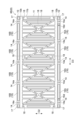
図1、図2、図7及び図8に示されるように、拘束部材4は、モジュール積層体2を第1方向D1の両側から挟む一対の拘束板8と、一対の拘束板8を連結する複数の連結部材9とを含む。一対の拘束板8は、負極端子7側の拘束板8A及び正極端子6側の拘束板8Bを含む。図7には、重力方向の下側に配置される拘束板8Bの内面が示されている。拘束板8Bは、モジュール積層体2の重力方向の下側に配置されている。重力方向の上側に配置される拘束板8Aは、拘束板8Bと同じ形状を有している。拘束板8Aには、後述の液体排出口16dが設けられていなくてもよい。 1, 2, 7, and 8, the restraint member 4 includes a pair of restraint plates 8 that sandwich the module stack 2 from both sides in the first direction D1, and a plurality of connecting members 9 that connect the pair of restraint plates 8. The pair of restraint plates 8 includes a restraint plate 8A on the negative terminal 7 side and a restraint plate 8B on the positive terminal 6 side. FIG. 7 shows the inner surface of the restraint plate 8B that is disposed on the lower side in the direction of gravity. The restraint plate 8B is disposed on the lower side in the direction of gravity of the module stack 2. The restraint plate 8A that is disposed on the upper side in the direction of gravity has the same shape as the restraint plate 8B. The restraint plate 8A does not need to be provided with a liquid outlet 16d, which will be described later.

一対の拘束板8は、第1方向D1において、モジュール積層体2を挟むように、モジュール積層体2の両側に積層されている。連結部材9は、一対の拘束板8を介して第1方向D1の両側からモジュール積層体2に拘束荷重を付加する。複数の蓄電モジュール3及び複数の集電板5は、一対の拘束板8により挟持されることで、モジュール積層体2としてユニット化されている。本実施形態では、連結部材9は、一対の拘束板8を締結するボルト9a及びナット9bによって構成されている。 The pair of restraining plates 8 are stacked on both sides of the module stack 2 in the first direction D1, sandwiching the module stack 2. The connecting member 9 applies a restraining load to the module stack 2 from both sides in the first direction D1 via the pair of restraining plates 8. The multiple energy storage modules 3 and multiple current collector plates 5 are sandwiched between the pair of restraining plates 8 and are unitized as the module stack 2. In this embodiment, the connecting member 9 is composed of a bolt 9a and a nut 9b that fasten the pair of restraining plates 8.

一対の絶縁板20は、絶縁性材料により形成される。一対の絶縁板20は、例えば、ポリプロピレン(PP)等の樹脂からなる。一対の絶縁板20は、負極端子7側の絶縁板20A及び正極端子6側の絶縁板20Bを含む。 The pair of insulating plates 20 is made of an insulating material. The pair of insulating plates 20 is made of a resin such as polypropylene (PP). The pair of insulating plates 20 includes an insulating plate 20A on the negative terminal 7 side and an insulating plate 20B on the positive terminal 6 side.

集電板5Aと拘束板8Aとの間には、絶縁板20Aが設けられる。絶縁板20Aは、集電板5Aと拘束板8Aとの間の絶縁性を確保するための部材である。絶縁板20Aは、集電板5Aと拘束板8Aとに接触している。絶縁板20Aは、第1方向D1においてモジュール積層体2上に積層されている。絶縁板20Aは、第1方向D1から見て、集電板5Aの全域と重なるように配置される。拘束板8Aは、第1方向D1において絶縁板20A上に積層され、少なくとも絶縁板20A及びモジュール積層体2に拘束荷重を付加する。 An insulating plate 20A is provided between the current collector plate 5A and the restraining plate 8A. The insulating plate 20A is a member for ensuring insulation between the current collector plate 5A and the restraining plate 8A. The insulating plate 20A is in contact with the current collector plate 5A and the restraining plate 8A. The insulating plate 20A is stacked on the module stack 2 in the first direction D1. The insulating plate 20A is arranged so as to overlap the entire area of the current collector plate 5A when viewed from the first direction D1. The restraining plate 8A is stacked on the insulating plate 20A in the first direction D1, and applies a restraining load to at least the insulating plate 20A and the module stack 2.

集電板5Bと拘束板8Bとの間には、絶縁板20Bが設けられる。絶縁板20Bは、集電板5Bと拘束板8Bとの間の絶縁性を確保するための部材である。絶縁板20Bは、集電板5Bと拘束板8Bとに接触している。絶縁板20Bは、第1方向D1においてモジュール積層体2上に積層されている。絶縁板20Bは、第1方向D1から見て、集電板5Bの全域と重なるように配置される。拘束板8Bは、第1方向D1において絶縁板20B上に積層され、少なくとも絶縁板20B及びモジュール積層体2に拘束荷重を付加する。 An insulating plate 20B is provided between the current collecting plate 5B and the restraining plate 8B. The insulating plate 20B is a member for ensuring insulation between the current collecting plate 5B and the restraining plate 8B. The insulating plate 20B is in contact with the current collecting plate 5B and the restraining plate 8B. The insulating plate 20B is stacked on the module stack 2 in the first direction D1. The insulating plate 20B is arranged so as to overlap the entire area of the current collecting plate 5B when viewed from the first direction D1. The restraining plate 8B is stacked on the insulating plate 20B in the first direction D1, and applies a restraining load to at least the insulating plate 20B and the module stack 2.

拘束板8は、第1方向D1から見て、蓄電モジュール3及び集電板5の面積よりも一回り大きい面積を有する矩形の金属板である。拘束板8の短手方向は、第2方向D2と一致している。拘束板8の長手方向は、第3方向D3と一致している。拘束板8は、本体部11及び一対の縁部10を有する。本体部11は、第1方向D1から見てモジュール積層体2と重なる。一対の縁部10は、本体部11から第2方向D2に延在する。一対の縁部10は、第1方向D1から見てモジュール積層体2と隣り合い、モジュール積層体2と重ならない。本実施形態では、一対の縁部10は、第2方向D2における本体部11の両側に設けられている。すなわち、本体部11は、第2方向D2において一対の縁部10に挟まれている。 The restraining plate 8 is a rectangular metal plate having an area slightly larger than the areas of the storage module 3 and the current collector plate 5 when viewed from the first direction D1. The short side direction of the restraining plate 8 coincides with the second direction D2. The long side direction of the restraining plate 8 coincides with the third direction D3. The restraining plate 8 has a main body portion 11 and a pair of edge portions 10. The main body portion 11 overlaps with the module stack 2 when viewed from the first direction D1. The pair of edge portions 10 extend from the main body portion 11 in the second direction D2. The pair of edge portions 10 are adjacent to the module stack 2 when viewed from the first direction D1, and do not overlap with the module stack 2. In this embodiment, the pair of edge portions 10 are provided on both sides of the main body portion 11 in the second direction D2. That is, the main body portion 11 is sandwiched between the pair of edge portions 10 in the second direction D2.

縁部10は、第1方向D1の外側(第1方向D1におけるモジュール積層体2は反対側)を向く外面10aと、第1方向D1の内側(第1方向D1におけるモジュール積層体2側)を向く内面10bと、を有している。本体部11は、第1方向D1の外側を向く外面11aと、第1方向D1の内側を向く内面11bと、を有している。内面11bは、絶縁板20と対向している。外面10aは、外面11aよりも第1方向D1の内側に位置している。内面10bは、内面11bよりも第1方向D1の内側に位置している。 The edge portion 10 has an outer surface 10a facing outward in the first direction D1 (the opposite side to the module stack 2 in the first direction D1) and an inner surface 10b facing inward in the first direction D1 (the side of the module stack 2 in the first direction D1). The main body portion 11 has an outer surface 11a facing outward in the first direction D1 and an inner surface 11b facing inward in the first direction D1. The inner surface 11b faces the insulating plate 20. The outer surface 10a is located more inward in the first direction D1 than the outer surface 11a. The inner surface 10b is located more inward in the first direction D1 than the inner surface 11b.

一対の縁部10は、拘束板8の長手方向(第3方向D3)に延在する外縁部分である。各縁部10は、複数(本実施形態では5つ)の係合部分14を有している。係合部分14は、ボルト9aが係合される部分である。複数の係合部分14は、各縁部10において、第3方向D3に沿って互いに離間するように配置されている。本実施形態では、複数の係合部分14は、第3方向D3において等間隔で縁部10に配置されている。 The pair of edges 10 are outer edge portions extending in the longitudinal direction (third direction D3) of the restraint plate 8. Each edge 10 has multiple (five in this embodiment) engaging portions 14. The engaging portions 14 are portions with which the bolts 9a engage. The multiple engaging portions 14 are arranged on each edge 10 so as to be spaced apart from one another along the third direction D3. In this embodiment, the multiple engaging portions 14 are arranged on the edge 10 at equal intervals in the third direction D3.

各係合部分14には、ボルト9aが挿通される挿通孔14aが設けられている。挿通孔14aは、係合部分14を第1方向D1に沿って貫通している。挿通孔14aは、外面10aと内面10bとを接続するように第1方向D1に沿って延在している。ボルト9aの頭部は、拘束板8Aの外面10a上に配置されている。ボルト9aの軸部の先端部(ネジ先)は、拘束板8Bの外面10aから突出している。ボルト9aの先端部には、ナット9bが螺合されている。ナット9bは、拘束板8Bの外面10a上に配置されている。 Each engagement portion 14 has an insertion hole 14a through which a bolt 9a is inserted. The insertion hole 14a penetrates the engagement portion 14 along the first direction D1. The insertion hole 14a extends along the first direction D1 so as to connect the outer surface 10a and the inner surface 10b. The head of the bolt 9a is disposed on the outer surface 10a of the restraint plate 8A. The tip (thread tip) of the shaft of the bolt 9a protrudes from the outer surface 10a of the restraint plate 8B. A nut 9b is screwed onto the tip of the bolt 9a. The nut 9b is disposed on the outer surface 10a of the restraint plate 8B.

各縁部10は、第1方向D1の内側(モジュール積層体2側、重力方向の上側)に開口する複数(本実施形態では4つ)の凹部16及び一対の凹部17を有している。凹部16及び凹部17は、第3方向D3に沿って延在している断面U字状の溝部である。凹部16の第3方向D3の長さは、凹部17の第3方向D3の長さよりも長い。一対の拘束板8は、互いの凹部16同士が第1方向D1において対向すると共に、互いの凹部17同士が第1方向D1において対向するように配置されている。 Each edge portion 10 has multiple (four in this embodiment) recesses 16 and a pair of recesses 17 that open inward in the first direction D1 (toward the module stack 2, upward in the direction of gravity). The recesses 16 and the recesses 17 are grooves with a U-shaped cross section that extend along the third direction D3. The length of the recesses 16 in the third direction D3 is longer than the length of the recesses 17 in the third direction D3. The pair of restraining plates 8 are arranged such that the recesses 16 face each other in the first direction D1 and the recesses 17 face each other in the first direction D1.

凹部16は、第2方向D2で互いに対向している側壁16a,16bと、底壁16cとを有している。第2方向D2の内側(モジュール積層体2側)に配置された側壁16aは、モジュール積層体2と第2方向D2で対向している。複数の凹部16は、第3方向D3において互いに隣り合う係合部分14間に配置されている。複数の凹部16は、集電板5に対応する位置に設けられている。すなわち、複数の凹部16の第2方向D2の位置範囲は、集電板5の第2方向D2の位置範囲と重なっている。 The recess 16 has side walls 16a, 16b that face each other in the second direction D2, and a bottom wall 16c. The side wall 16a that is arranged on the inside of the second direction D2 (the module stack 2 side) faces the module stack 2 in the second direction D2. The multiple recesses 16 are arranged between adjacent engagement portions 14 in the third direction D3. The multiple recesses 16 are provided at positions corresponding to the current collector plate 5. In other words, the positional range of the multiple recesses 16 in the second direction D2 overlaps with the positional range of the current collector plate 5 in the second direction D2.

一方の縁部10に設けられた凹部16Aは、第1方向D1から見て、集電板5Cに設けられた流路5aの出口5cと、第2方向D2において隣り合うように設けられている。凹部16Aは、第1方向D1から見て、第2方向D2において複数の出口5cと隣り合うように第3方向D3に沿って延在している。他方の縁部10に設けられた凹部16Bは、第1方向D1から見て、集電板5Cに設けられた流路5aの入口5bと隣り合うように設けられている。凹部16Bは、第1方向D1から見て、複数の入口5bと隣り合うように第3方向D3に沿って延在している。 The recess 16A provided on one edge 10 is provided adjacent to the outlet 5c of the flow path 5a provided in the current collector 5C in the second direction D2 when viewed from the first direction D1. The recess 16A extends along the third direction D3 so as to be adjacent to the multiple outlets 5c in the second direction D2 when viewed from the first direction D1. The recess 16B provided on the other edge 10 is provided adjacent to the inlet 5b of the flow path 5a provided in the current collector 5C when viewed from the first direction D1. The recess 16B extends along the third direction D3 so as to be adjacent to the multiple inlets 5b when viewed from the first direction D1.

係合部分14を介して一対の凹部17とそれぞれ隣り合う両端の凹部16Aには、凹部16A内に溜まった水を抜くための液体排出口16dが設けられている。液体排出口16dは、底壁16cを第1方向D1において貫通する貫通孔である。本発明者らの調査によれば、凹部17と隣り合う両端の凹部16Aには、中央の凹部16Aよりも水が溜まり易いことが分かった。これは、モジュール積層体2の中央部よりも外側部分で蓄電モジュール3の温度変化が大きくなり、結露が生じ易いためと考えられる。また、冷却用流体の流量が、第3方向D3の中央部に設けられた流路5aよりも両端部に設けられた流路5aで大きくなり、水滴が飛ばされ易いためとも考えられる。 The recesses 16A at both ends adjacent to the pair of recesses 17 via the engagement portion 14 are provided with liquid outlets 16d for draining water accumulated in the recesses 16A. The liquid outlets 16d are through holes penetrating the bottom wall 16c in the first direction D1. According to the inventors' investigation, it was found that water tends to accumulate in the recesses 16A at both ends adjacent to the recess 17 more easily than in the central recess 16A. This is thought to be because the temperature change of the storage module 3 is greater in the outer parts than in the central part of the module stack 2, making condensation more likely to occur. It is also thought to be because the flow rate of the cooling fluid is greater in the flow paths 5a at both ends than in the flow path 5a at the central part in the third direction D3, making it easier for water droplets to be blown away.

凹部17は、第2方向D2で互いに対向している側壁と、底壁とを有している。一対の凹部17は、各縁部10の第3方向D3の一対の端部に配置されている。一対の凹部17の間には、複数の係合部分14及び複数の凹部16が配置されている。一対の凹部17は、第2方向D2において一対の検出素子12に対応する位置に設けられている。すなわち、各凹部17の第2方向D2の位置範囲は、対応する検出素子12の第2方向D2の位置範囲と重なっている。 The recesses 17 have side walls and a bottom wall that face each other in the second direction D2. A pair of recesses 17 are arranged at a pair of ends in the third direction D3 of each edge portion 10. A plurality of engagement portions 14 and a plurality of recesses 16 are arranged between the pair of recesses 17. The pair of recesses 17 are provided at positions corresponding to the pair of detection elements 12 in the second direction D2. In other words, the positional range of each recess 17 in the second direction D2 overlaps with the positional range of the corresponding detection element 12 in the second direction D2.

図7に示されるように、本体部11は、第1方向D1の内側に開口する複数の凹部18を有している。複数の凹部18は、様々な形状を有している。凹部16、凹部17及び凹部18は、拘束板8の肉盗み部(薄肉部)として機能している。 As shown in FIG. 7, the main body 11 has a number of recesses 18 that open inward in the first direction D1. The recesses 18 have various shapes. The recesses 16, 17, and 18 function as reduced-material portions (thin-walled portions) of the restraining plate 8.

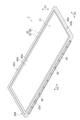
図2及び図8に示されるように、各絶縁板20は、モジュール積層体2と本体部11との間に配置された底部20aと、モジュール積層体2と側壁16aとの間に配置された一対の側部20bとを有している。絶縁板20Aの底部20aは、集電板5Aと本体部11とに接触して配置されている。絶縁板20Bの底部20aは、集電板5Bと本体部11とに接触して配置されている。 As shown in Figures 2 and 8, each insulating plate 20 has a bottom 20a disposed between the module stack 2 and the main body 11, and a pair of side portions 20b disposed between the module stack 2 and the sidewall 16a. The bottom 20a of insulating plate 20A is disposed in contact with the current collector 5A and the main body 11. The bottom 20a of insulating plate 20B is disposed in contact with the current collector 5B and the main body 11.

底部20aは、矩形板状であり、第2方向D2及び第3方向D3に沿って配置されている。一対の側部20bは、底部20aの第2方向D2の両端部に接続され、第1方向D1に延在している。各側部20bは、側壁16aと第2方向D2において対向している。側部20bは、第1方向D1において側壁16aの全体を覆う高さ(第1方向D1の長さ)を有している。すなわち、側部20bの第1方向D1における高さは、側壁16aの第1方向D1における高さ以上である。各側部20bは、第3方向D3に沿って延在し、凹部17の側壁及び係合部分14とも第2方向D2で対向している。各側部20bは、第3方向D3において縁部10の全体を覆う長さを有している。 The bottom 20a is a rectangular plate-like member and is disposed along the second direction D2 and the third direction D3. The pair of side portions 20b are connected to both ends of the bottom 20a in the second direction D2 and extend in the first direction D1. Each side portion 20b faces the side wall 16a in the second direction D2. The side portion 20b has a height (length in the first direction D1) that covers the entire side wall 16a in the first direction D1. That is, the height of the side portion 20b in the first direction D1 is equal to or greater than the height of the side wall 16a in the first direction D1. Each side portion 20b extends along the third direction D3 and faces the side wall of the recess 17 and the engagement portion 14 in the second direction D2. Each side portion 20b has a length that covers the entire edge portion 10 in the third direction D3.

次に、本実施形態に係る蓄電装置1の作用及び効果について説明する。 Next, we will explain the operation and effects of the energy storage device 1 according to this embodiment.

蓄電装置1では、拘束板8の縁部10は、第1方向D1の内側に開口する凹部16を有している。凹部16には液体排出口16dが設けられているので、凹部16に水滴が溜まることが抑制される。モジュール積層体2と拘束板8の間に配置された絶縁板20は、モジュール積層体2と拘束板8の本体部11との間に配置された底部20aだけでなく、モジュール積層体2と凹部16の側壁16aとの間に配置された側部20bを有している。側部20bの第1方向D1における高さは、側壁16aの第1方向D1における高さ以上である。このため、仮に凹部16に水滴が溜まったとしても、凹部16の側壁を超えてモジュール積層体2側に侵入することが絶縁板20によって抑制される。以上により、蓄電モジュール3間で短絡が生じることが抑制される。 In the energy storage device 1, the edge 10 of the restraining plate 8 has a recess 16 that opens to the inside in the first direction D1. The recess 16 is provided with a liquid outlet 16d, so that water droplets are prevented from accumulating in the recess 16. The insulating plate 20 arranged between the module stack 2 and the restraining plate 8 has not only a bottom 20a arranged between the module stack 2 and the main body 11 of the restraining plate 8, but also a side 20b arranged between the module stack 2 and the side wall 16a of the recess 16. The height of the side 20b in the first direction D1 is equal to or greater than the height of the side wall 16a in the first direction D1. Therefore, even if water droplets accumulate in the recess 16, the insulating plate 20 prevents the water droplets from entering the module stack 2 side beyond the side wall of the recess 16. As a result, a short circuit between the energy storage modules 3 is prevented.

モジュール積層体2は、第1方向D1において互いに隣り合う蓄電モジュール3間に設けられた集電板5Cを有し、集電板5Cには、流路5aが設けられている。凹部16は、第1方向D1から見て、流路5aの出口5cと第2方向D2において隣り合うように設けられていている。このため、水滴が冷却用流体により出口5cから飛ばされ、出口5cと隣り合う凹部16に溜まり易い。よって、液体排出口16d及び絶縁板20の構成がより有効である。 The module stack 2 has a current collector 5C provided between adjacent storage modules 3 in the first direction D1, and the current collector 5C has a flow path 5a. When viewed from the first direction D1, the recess 16 is provided so as to be adjacent to the outlet 5c of the flow path 5a in the second direction D2. Therefore, water droplets are blown away from the outlet 5c by the cooling fluid and tend to accumulate in the recess 16 adjacent to the outlet 5c. Therefore, the configuration of the liquid outlet 16d and the insulating plate 20 is more effective.

流路5aは、第3方向D3に沿って複数配列されており、凹部16は、第1方向D1から見て、複数の出口5cと第2方向D2において隣り合うように第3方向D3に沿って延在していている。このため、凹部16には、水滴が更に溜まり易い。よって、液体排出口16d及び絶縁板20の構成がより一層有効である。 The flow paths 5a are arranged in a row along the third direction D3, and the recesses 16 extend along the third direction D3 so as to be adjacent to the outlets 5c in the second direction D2 when viewed from the first direction D1. This makes it even easier for water droplets to accumulate in the recesses 16. This makes the configuration of the liquid outlet 16d and the insulating plate 20 even more effective.

封止体52は、外周面62aに設けられ、電極積層体51の外側に向けて張り出す庇部64を有する。このため、凹部16には、庇部64によって水滴が更に溜まり易い。よって、液体排出口16d及び絶縁板20の構成がより有効である。 The sealing body 52 has an overhanging portion 64 that is provided on the outer peripheral surface 62a and extends outward from the electrode stack 51. Therefore, the overhanging portion 64 makes it easier for water droplets to accumulate in the recess 16. Therefore, the configuration of the liquid outlet 16d and the insulating plate 20 is more effective.

液体排出口16dは、凹部16の底壁16cを第1方向D1において貫通する貫通孔である。このため、液体排出口16dが凹部16の側壁16a,16bに設けられている場合に比べて、凹部16に水滴が溜まり難い。 The liquid outlet 16d is a through-hole that penetrates the bottom wall 16c of the recess 16 in the first direction D1. Therefore, water droplets are less likely to accumulate in the recess 16 than if the liquid outlet 16d were provided in the side walls 16a and 16b of the recess 16.

本開示は上記実施形態に限定されない。 This disclosure is not limited to the above embodiments.

上記実施形態では、液体排出口16dは、底壁16cに設けられているが、第2方向D2の外側(モジュール積層体2の反対側)に配置された側壁16bに設けられていてもよい。この場合、液体排出口16dは、側壁16bを第2方向D2に貫通する貫通孔であってもよい。 In the above embodiment, the liquid outlet 16d is provided in the bottom wall 16c, but it may be provided in the side wall 16b arranged on the outside of the second direction D2 (opposite the module stack 2). In this case, the liquid outlet 16d may be a through hole that penetrates the side wall 16b in the second direction D2.

上記実施形態では、拘束板8Bが拘束板8A及びモジュール積層体2より重力方向の下側に配置されるが、拘束板8Bが拘束板8A及びモジュール積層体2より重力方向の上側に配置されてもよい。この場合、拘束板8Aに液体排出口16dが設けられる。一対の拘束板8の両方に液体排出口16dが設けられてもよい。上記実施形態では、凹部17と隣り合う両端の凹部16Aに液体排出口16dが設けられ、中央の凹部16Aには液体排出口16dが設けられていないが、全ての凹部16Aに液体排出口16dが設けられていてもよい。 In the above embodiment, the restraint plate 8B is disposed below the restraint plate 8A and the module stack 2 in the direction of gravity, but the restraint plate 8B may be disposed above the restraint plate 8A and the module stack 2 in the direction of gravity. In this case, a liquid outlet 16d is provided in the restraint plate 8A. A liquid outlet 16d may be provided in both of the pair of restraint plates 8. In the above embodiment, the liquid outlet 16d is provided in the recesses 16A at both ends adjacent to the recess 17, and the central recess 16A is not provided with a liquid outlet 16d, but all recesses 16A may be provided with a liquid outlet 16d.

上記実施形態では、外面10aは、外面11aよりも第1方向D1の内側に位置しているが、外面10aは、外面11aと同一平面上に位置していてもよいし、外面11aよりも第1方向D1の外側に位置していてもよい。内面10bは、内面11bよりも第1方向D1の内側に位置しているが、内面10bは、内面11bと同一平面上に位置していてもよいし、内面11bよりも第1方向D1の外側に位置していてもよい。 In the above embodiment, the outer surface 10a is located inside the outer surface 11a in the first direction D1, but the outer surface 10a may be located on the same plane as the outer surface 11a or may be located outside the outer surface 11a in the first direction D1. The inner surface 10b is located inside the inner surface 11b in the first direction D1, but the inner surface 10b may be located on the same plane as the inner surface 11b or may be located outside the inner surface 11b in the first direction D1.

上記実施形態では、第1方向D1から見た集電板5の面積は、蓄電モジュール3の面積よりも小さいが、放熱性の向上の観点から、蓄電モジュール3の面積と同一であってもよく、蓄電モジュール3の面積よりも大きくてもよい。 In the above embodiment, the area of the current collector 5 as viewed from the first direction D1 is smaller than the area of the storage module 3, but from the viewpoint of improving heat dissipation, it may be the same as the area of the storage module 3 or may be larger than the area of the storage module 3.

絶縁板20は、底部20aの第3方向D3の両端部に接続され、第1方向D1に延在する一対の側部を更に有する箱形状であってもよい。封止体52は、庇部64及びリブ65を有していなくてもよい。 The insulating plate 20 may be box-shaped and connected to both ends of the bottom 20a in the third direction D3 and further having a pair of side portions extending in the first direction D1. The sealing body 52 may not have the eaves portion 64 and the rib 65.

1…蓄電装置、2…モジュール積層体、3…蓄電モジュール、5,5A,5B,5C…集電板、5a…流路、5b…入口、5c…出口、8,8A,8B…拘束板、10…縁部、11…本体部、16,16A,16B…凹部、16a…側壁、16c…底壁、16d…液体排出口、20,20A,20B…絶縁板、20a…底部、20b…側部、51…電極積層体、51a…側面、52…封止体、53…セパレータ、62a…外周面、64…庇部、V…内部空間。 1...electricity storage device, 2...module stack, 3...electricity storage module, 5, 5A, 5B, 5C...current collector plate, 5a...flow path, 5b...inlet, 5c...outlet, 8, 8A, 8B...restraint plate, 10...edge, 11...main body, 16, 16A, 16B...recess, 16a...side wall, 16c...bottom wall, 16d...liquid outlet, 20, 20A, 20B...insulating plate, 20a...bottom, 20b...side, 51...electrode stack, 51a...side surface, 52...seal, 53...separator, 62a...outer periphery, 64...eaves, V...internal space.

Claims (5)

第1方向において積層された複数の蓄電モジュールを有するモジュール積層体と、
前記第1方向において前記モジュール積層体上に積層された絶縁板と、
前記第1方向において前記絶縁板上に積層され、前記モジュール積層体及び前記絶縁板に拘束荷重を付加する拘束板と、を備え、
前記拘束板は、前記モジュール積層体の重力方向の下側に配置され、前記第1方向から見て前記モジュール積層体と重なる本体部と、前記第1方向から見て前記モジュール積層体と隣り合う縁部と、を有し、
前記縁部は、前記第1方向の内側に開口する凹部を有し、
前記凹部は、前記第1方向に直交する第2方向で前記モジュール積層体と対向する側壁を有し、
前記絶縁板は、前記モジュール積層体と前記本体部との間に配置された底部と、前記モジュール積層体と前記側壁との間に配置された側部と、を有し、
前記側部の前記第1方向における高さは、前記側壁の前記第1方向における高さ以上であり、
前記凹部には、液体排出口が設けられている、
蓄電装置。
a module stack including a plurality of power storage modules stacked in a first direction;
an insulating plate stacked on the module stack in the first direction;
a restraint plate that is stacked on the insulating plate in the first direction and applies a restraint load to the module stack and the insulating plate,
the restraint plate is disposed below the module stack in a gravity direction, and has a main body portion overlapping the module stack when viewed from the first direction, and an edge portion adjacent to the module stack when viewed from the first direction,
The edge portion has a recess that opens to the inside in the first direction,
the recess has a side wall facing the module stack in a second direction perpendicular to the first direction,
the insulating plate has a bottom portion disposed between the module stack and the body portion and a side portion disposed between the module stack and the side wall;
a height of the side portion in the first direction is equal to or greater than a height of the side wall in the first direction;
The recess is provided with a liquid outlet.
Energy storage device.
前記モジュール積層体は、隣り合う前記蓄電モジュール間に設けられた集電板を有し、
前記集電板には、前記第1方向に直交する第2方向に延在し、冷却用流体が流入する入口と、前記冷却用流体が流出する出口と、を有する流路が設けられており、
前記凹部は、前記第1方向から見て、前記出口と隣り合うように設けられている、
請求項1に記載の蓄電装置。
the module stack has a current collector plate provided between adjacent ones of the power storage modules,
The current collector plate is provided with a flow path extending in a second direction perpendicular to the first direction and having an inlet through which a cooling fluid flows and an outlet through which the cooling fluid flows out,
The recess is provided adjacent to the outlet when viewed from the first direction.
The power storage device according to claim 1 .
前記流路は、前記第1方向と前記第2方向とに直交する第3方向に沿って複数配列されており、
前記凹部は、前記第1方向から見て、複数の前記出口と隣り合うように前記第3方向に沿って延在している、
請求項2に記載の蓄電装置。
The flow channels are arranged in a third direction perpendicular to the first direction and the second direction,
The recess extends along the third direction so as to be adjacent to the plurality of outlets when viewed from the first direction.
The power storage device according to claim 2 .
前記複数の蓄電モジュールのそれぞれは、セパレータを介して前記第1方向において積層された複数の電極を含む電極積層体と、前記電極積層体の前記第1方向に沿う側面を取り囲むとともに、隣り合う前記電極間に形成された内部空間を封止する封止体と、を有し、
前記封止体は、前記第1方向に沿う外周面と、前記外周面に設けられ、前記電極積層体の外側に向けて張り出す庇部と、を有する、
請求項1~3のいずれか一項に記載の蓄電装置。
Each of the plurality of power storage modules includes an electrode stack including a plurality of electrodes stacked in the first direction with separators interposed therebetween, and a sealing body that surrounds a side surface of the electrode stack along the first direction and seals an internal space formed between adjacent electrodes,
The sealing body has an outer peripheral surface along the first direction, and an overhang portion provided on the outer peripheral surface and extending outward toward an outside of the electrode stack.
The power storage device according to any one of claims 1 to 3.
前記液体排出口は、前記凹部の底壁を前記第1方向において貫通する貫通孔である、
請求項1~4のいずれか一項に記載の蓄電装置。
the liquid discharge port is a through hole penetrating a bottom wall of the recess in the first direction;
The power storage device according to any one of claims 1 to 4.
JP2021082545A 2021-05-14 2021-05-14 Power storage device Active JP7572909B2 (en)

Priority Applications (1)

Application Number Priority Date Filing Date Title
JP2021082545A JP7572909B2 (en) 2021-05-14 2021-05-14 Power storage device

Applications Claiming Priority (1)

Application Number Priority Date Filing Date Title
JP2021082545A JP7572909B2 (en) 2021-05-14 2021-05-14 Power storage device

Publications (2)

Publication Number Publication Date
JP2022175827A JP2022175827A (en) 2022-11-25
JP7572909B2 true JP7572909B2 (en) 2024-10-24

Family

ID=84145560

Family Applications (1)

Application Number Title Priority Date Filing Date
JP2021082545A Active JP7572909B2 (en) 2021-05-14 2021-05-14 Power storage device

Country Status (1)

Country Link
JP (1) JP7572909B2 (en)

Citations (5)

* Cited by examiner, † Cited by third party
Publication number Priority date Publication date Assignee Title
JP2014165004A (en) 2013-02-25 2014-09-08 Mitsubishi Heavy Ind Ltd Battery pack
WO2020138110A1 (en) 2018-12-25 2020-07-02 トヨタ自動車株式会社 Bipolar battery and power storage device
JP2020135920A (en) 2019-02-12 2020-08-31 三菱自動車工業株式会社 In-vehicle battery pack
JP2021012850A (en) 2019-07-09 2021-02-04 株式会社豊田自動織機 Power storage device
JP2021015771A (en) 2019-07-16 2021-02-12 株式会社豊田自動織機 Power storage device

Patent Citations (5)

* Cited by examiner, † Cited by third party
Publication number Priority date Publication date Assignee Title
JP2014165004A (en) 2013-02-25 2014-09-08 Mitsubishi Heavy Ind Ltd Battery pack
WO2020138110A1 (en) 2018-12-25 2020-07-02 トヨタ自動車株式会社 Bipolar battery and power storage device
JP2020135920A (en) 2019-02-12 2020-08-31 三菱自動車工業株式会社 In-vehicle battery pack
JP2021012850A (en) 2019-07-09 2021-02-04 株式会社豊田自動織機 Power storage device
JP2021015771A (en) 2019-07-16 2021-02-12 株式会社豊田自動織機 Power storage device

Also Published As

Publication number Publication date
JP2022175827A (en) 2022-11-25

Similar Documents

Publication Publication Date Title
JP7226269B2 (en) Pressure regulating valve structure and power storage module
JP7315397B2 (en) power storage device
JP6874852B2 (en) Power storage module
JP6915567B2 (en) Power storage module
JP6959514B2 (en) Power storage module, manufacturing method of power storage module, and manufacturing method of power storage device
CN113178610B (en) Power storage device
JP2020024871A (en) Power storage module and electrode unit
JP7079694B2 (en) Power storage module
JP7572909B2 (en) Power storage device
JP7116631B2 (en) storage module
JP7123717B2 (en) storage module
JP7551566B2 (en) Power storage device
JP7420566B2 (en) Power storage device
JP2020030985A (en) Power storage module
JP7079695B2 (en) Power storage module
JP7056466B2 (en) Power storage module
JP7116632B2 (en) storage module
JP7164459B2 (en) storage module
JP7103033B2 (en) Power storage module and manufacturing method of power storage module
JP7070279B2 (en) Power storage module
JP7042204B2 (en) Power storage module
JP7074614B2 (en) Power storage module
JP7056167B2 (en) Power storage module and manufacturing method of power storage module
JP7060956B2 (en) Power storage module
JP7299849B2 (en) power storage device

Legal Events

Date Code Title Description
A621 Written request for application examination

Free format text: JAPANESE INTERMEDIATE CODE: A621

Effective date: 20230912

A977 Report on retrieval

Free format text: JAPANESE INTERMEDIATE CODE: A971007

Effective date: 20240814

TRDD Decision of grant or rejection written
A01 Written decision to grant a patent or to grant a registration (utility model)

Free format text: JAPANESE INTERMEDIATE CODE: A01

Effective date: 20241008

A61 First payment of annual fees (during grant procedure)

Free format text: JAPANESE INTERMEDIATE CODE: A61

Effective date: 20241011

R150 Certificate of patent or registration of utility model

Ref document number: 7572909

Country of ref document: JP

Free format text: JAPANESE INTERMEDIATE CODE: R150