JP7572011B2 - Separator and compressed air circuit using same - Google Patents
Separator and compressed air circuit using same Download PDFInfo
- Publication number
- JP7572011B2 JP7572011B2 JP2022125474A JP2022125474A JP7572011B2 JP 7572011 B2 JP7572011 B2 JP 7572011B2 JP 2022125474 A JP2022125474 A JP 2022125474A JP 2022125474 A JP2022125474 A JP 2022125474A JP 7572011 B2 JP7572011 B2 JP 7572011B2
- Authority
- JP
- Japan
- Prior art keywords
- connection port
- flow path
- separator
- air
- liquid
- Prior art date
- Legal status (The legal status is an assumption and is not a legal conclusion. Google has not performed a legal analysis and makes no representation as to the accuracy of the status listed.)
- Active
Links
- 239000007788 liquid Substances 0.000 claims description 87
- 230000006698 induction Effects 0.000 claims description 25
- 238000000926 separation method Methods 0.000 claims description 16
- 230000002093 peripheral effect Effects 0.000 claims description 13
- 241001125929 Trisopterus luscus Species 0.000 description 10
- 238000000034 method Methods 0.000 description 2
- 238000009825 accumulation Methods 0.000 description 1
- 238000010586 diagram Methods 0.000 description 1
- 230000000694 effects Effects 0.000 description 1
- 230000007257 malfunction Effects 0.000 description 1
- 238000012986 modification Methods 0.000 description 1
- 230000004048 modification Effects 0.000 description 1
- 238000006467 substitution reaction Methods 0.000 description 1
Images


Landscapes
- Fluid-Pressure Circuits (AREA)
- Separating Particles In Gases By Inertia (AREA)
- Cyclones (AREA)
Description
本発明は、ループ管路内に設けられ、内部を通過する空気流から液分を除去する分離器、及びその分離器が用いられる圧縮空気圧回路に関する。 The present invention relates to a separator that is installed in a loop pipe and removes liquid from the air flow passing through it, and to a compressed air pressure circuit in which the separator is used.
従来、特許文献1に記載の圧縮空気圧回路が知られている。この圧縮空気圧回路は、環状のループ管路を有すること特徴としている。ループ管路には一又は複数の分配管路が結合しており、各分配管路に空圧機器(例えば、エアガン、エアシリンダ等)が接続されている。そして、ループ管路に対して空気圧縮機から圧縮空気が供給される。このような圧縮空気圧回路では、いずれかの空圧機器の使用に際して、ループ管路から分配管路を通してその空圧機器に圧縮空気が供給され、その圧縮空気によって空圧機器が動作、例えば、エアガンから高圧空気が噴射され、また、例えば、エアシリンダが動作する。 Conventionally, a compressed air pressure circuit as described in Patent Document 1 is known. This compressed air pressure circuit is characterized by having a ring-shaped loop pipe. One or more distribution pipes are connected to the loop pipe, and each distribution pipe is connected to a pneumatic device (e.g., an air gun, an air cylinder, etc.). Compressed air is supplied to the loop pipe from an air compressor. In such a compressed air pressure circuit, when any pneumatic device is used, compressed air is supplied to the pneumatic device from the loop pipe through the distribution pipe, and the pneumatic device is operated by the compressed air, for example, high-pressure air is sprayed from an air gun, or an air cylinder is operated, for example.
上述したようなループ管路を含む圧縮空気圧回路では、凝縮液等の液分が圧縮空気とともにループ管路を流れる。このようにループ管路を流れる液分が分配管路を通して機器に流れ込み、機器が正常に動作できないおそれがある。このような機器への液分の流れ込みを防止するために、通常、ループ管路から分岐して機器に延びる分配管路に分離器(セパレータ)が設けられる。これにより、ループ管路から分配管路に進入する液分が分離器により除去されて、液分が機器に流れ込むことを防止することができる。 In a compressed air circuit including a loop line as described above, liquids such as condensate flow through the loop line together with the compressed air. The liquid flowing through the loop line in this way may flow into equipment through the distribution line, causing the equipment to malfunction. To prevent such liquids from flowing into the equipment, a separator is usually provided in the distribution line that branches off from the loop line and extends to the equipment. This allows the separator to remove liquids that enter the distribution line from the loop line, preventing the liquid from flowing into the equipment.
しかし、従来の分離器(特許文献1、図3参照)は、ループ管路から分配管路に流入する圧縮空気から液分を除去するものであるため、ループ管路内に液分が溜まって当該ループ管路内での圧縮空気の流れに支障をきたすおそれがある。また、圧縮空気を利用する空圧機器が接続される分配管路ごとに分離器を設ける必要があって、ループ管路に接続すべき分離器の数が増大してしまう。 However, conventional separators (see Patent Document 1, Figure 3) remove liquid from compressed air flowing from a loop line into a distribution line, which can lead to liquid accumulating in the loop line and disrupting the flow of compressed air in the loop line. In addition, a separator must be provided for each distribution line to which a pneumatic device that uses compressed air is connected, which increases the number of separators that must be connected to the loop lines.
本発明は、このような事情に鑑みてなされたもので、ループ管路内に液分が溜まることを抑制するとともに、ループ管路に接続すべき分離器の数を低減させることができる分離器を提供するものである。 The present invention was made in consideration of these circumstances, and provides a separator that can prevent liquid from accumulating in the loop pipeline and reduce the number of separators that need to be connected to the loop pipeline.
また、本発明は、ループ管路内に液分が溜まることが抑制されるとともに、ループ管路に接続すべき複数(多く)の空圧機器それぞれに対して分離器を設ける必要がなく、ループ管路に接続すべき分離器の数を低減させることができる圧縮空気圧回路を提供するものである。 The present invention also provides a compressed air circuit that prevents liquid from accumulating in the loop pipeline, eliminates the need to provide a separator for each of the multiple (many) pneumatic devices that are to be connected to the loop pipeline, and reduces the number of separators that must be connected to the loop pipeline.
本発明に係る分離器は、圧縮空気が流れるループ管路内に設けられ、内部を通過する空気流から液分を除去する分離器であって、空気が流入する第1接続口部と、前記ループ管路に直列的に接続される第2接続口部及び第3接続口部と、流入する空気から液分を除去する気液分離部と、前記第1接続口部から流入する空気を前記気液分離部に導く入り流路と、前記気液分離部により液分が除去された空気を前記第2接続口部及び前記第3接続口部のそれぞれに導く出流路と、を有し、更に、ヘッド部と、前記ヘッド部から下方に続き、円筒状の内周面を有するケース体と、を有し、前記第1接続口部、前記第2接続口部、及び前記第3接続口部は、前記ヘッド部に設けられ、前記気液分離部は、前記ケース体内に、当該ケース体の円筒状の内周面と同軸的に配置され、下方に向かって徐々に広がるテーパー状の外周面を有するテーパー筒体を有し、前記入り流路は、前記ヘッド部内において、前記第1接続口部から流入する空気を前記ケース体内に配置された前記テーパー筒体の外周面に導く流路として形成され、前記出流路は、前記テーパー筒体の内部を通る第1流路と、前記第1流路に連通し、前記ヘッド部内に形成された気体送出し室と、前記気体送出し室から前記第2接続口部に続く第2流路と、前記気体送出し室から前記第3接続口部に続く第3流路と、を有する構成となる。
The separator according to the present invention is provided in a loop pipe through which compressed air flows, and removes liquid from an air flow passing therethrough, the separator having a first connection port into which air flows in, a second connection port and a third connection port connected in series to the loop pipe, a gas-liquid separation section that removes liquid from the inflowing air, an inlet flow path that guides the air flowing in from the first connection port to the gas-liquid separation section, and an outlet flow path that guides the air from which liquid has been removed by the gas-liquid separation section to each of the second connection port and the third connection port, and further having a head section, and a case body that continues downward from the head section and has a cylindrical inner circumferential surface, is provided in the head portion, the gas-liquid separation unit is arranged within the case body coaxially with the cylindrical inner peripheral surface of the case body and has a tapered cylinder having a tapered outer peripheral surface that gradually widens downward, the inlet flow path is formed within the head portion as a flow path that guides air flowing in from the first connection port portion to the outer peripheral surface of the tapered cylinder arranged within the case body, and the outlet flow path has a first flow path that passes through the inside of the tapered cylinder, a gas delivery chamber that is connected to the first flow path and formed in the head portion, a second flow path that continues from the gas delivery chamber to the second connection port portion, and a third flow path that continues from the gas delivery chamber to the third connection port portion .
このような構成により、第1接続口部から流入する空気は、入り流路を通って気液分離部に導かれる。気液分離部により前記入り流路を通って導かれる空気から液分が除去され、その液分が除去された空気が出流路を通って第2接続口部及び第3接続口部のそれぞれに導かれる。そして、液分が除去された空気が第2接続口部及び第3接続口部からループ管路に流出する。更に詳細には、ヘッド部の第1接続口部から流入する空気は、当該ヘッド部において入り流路を通って、前記ヘッド部の下方に続くケース体内に収容されたテーパー筒体の外周面に導かれる。テーパー筒体の外周面に導かれる空気がその外周面に沿って回転しながら徐々に下方に向って進む過程で遠心力によりその空気から液分が除去される。液分が除去された空気は、テーパー筒体の最も広がった下端部から当該テーパー筒体の内部(第1流路)を通ってヘッド部内に形成された気体送出し室に流入する。そして、前記液分の除去された空気が気体送出し室から第2流路及び第3流路のそれぞれを通って、第2接続口部及び前記第3接続口部のそれぞれからループ管路に流出する。
With this configuration, air flowing in from the first connection port is guided to the gas-liquid separator through the inlet flow path. The gas-liquid separator removes liquid from the air guided through the inlet flow path, and the air from which the liquid has been removed is guided through the outlet flow path to the second connection port and the third connection port. The air from which the liquid has been removed flows out from the second connection port and the third connection port into the loop duct. More specifically, air flowing in from the first connection port of the head portion is guided through the inlet flow path in the head portion to the outer circumferential surface of a tapered cylinder housed in a case body continuing below the head portion. As the air guided to the outer circumferential surface of the tapered cylinder rotates along the outer circumferential surface and gradually moves downward, the liquid is removed from the air by centrifugal force. The air from which the liquid has been removed flows from the widest lower end of the tapered cylinder through the inside of the tapered cylinder (first flow path) into the gas delivery chamber formed in the head portion. Then, the air from which the liquid has been removed flows from the gas delivery chamber through the second flow path and the third flow path, and flows out from the second connection port and the third connection port into the loop pipe.
本発明に係る分離器において、前記入り流路としての前記流路は、前記第1接続口部から流入する空気を回転させながら前記ケース体内に配置された前記テーパー筒体の外周面に導く回転誘導流路を含む、構成とすることができる。 In the separator according to the present invention, the flow path serving as the inlet flow path can be configured to include a rotation induction flow path that rotates the air flowing in from the first connection port and guides it to the outer circumferential surface of the tapered cylinder disposed within the case.
このような構成により、回転誘導流路によって空気を回転させながらケース体内に配置された気液分離部としてのテーパー筒体の外周面に導かれるので、前記テーパー筒体の外周面を空気がより高速に回転することができる。その結果、テーパー筒体の外周面に沿って回転する空気から効果的に液分を除去することができる。 With this configuration, the air is rotated by the rotation induction flow path and guided to the outer circumferential surface of the tapered cylinder, which acts as a gas-liquid separator and is disposed inside the case body, allowing the air to rotate at higher speeds around the outer circumferential surface of the tapered cylinder. As a result, liquid can be effectively removed from the air rotating along the outer circumferential surface of the tapered cylinder.
本発明に係る分離器は、圧縮空気が流れるループ管路内に設けられ、内部を通過する空気流から液分を除去する分離器であって、空気が流入する第1接続口部と、前記ループ管路に直列的に接続される第2接続口部及び第3接続口部と、流入する空気から液分を除去する気液分離部と、前記第1接続口部から流入する空気を前記気液分離部に導く入り流路と、前記気液分離部により液分が除去された空気を前記第2接続口部及び前記第3接続口部のそれぞれに導く出流路と、を有し、更に、ヘッド部と、前記ヘッド部から下方に続き、円筒状の内周面を有するケース体と、を有し、前記第1接続口部、前記第2接続口部、及び前記第3接続口部は、前記ヘッド部に設けられ、前記気液分離部は、前記ケース体内に設けられ、当該ケース体の円筒状の内周面と同軸的に配置され、通過する空気を前記ケース体の内周面に沿って回転するように誘導する回転誘導リング体と、前記回転誘導リング体の下方に当該回転誘導リング体と同軸的に配置される円筒体と、を有し、前記入り流路は、前記ヘッド部内において、前記第1接続口から流入する空気を前記ケース体内に配置された回転誘導リング体に導く流路として形成され、前記出流路は、前記円筒体の内部及び前記回転誘導リング体の中央空間を含む第1流路と、前記第1流路に続き、前記ヘッド部内に形成された気体送出し室と、前記気体送出し室から前記第2接続口部に続く第2流路と、前記気体送出し室から前記第3 接続口部に続く第3流路と、を有する構成となる。
The separator according to the present invention is provided in a loop pipe through which compressed air flows, and removes liquid from an air flow passing therethrough, the separator having a first connection port into which air flows in, a second connection port and a third connection port connected in series to the loop pipe, a gas-liquid separation section that removes liquid from the inflowing air, an inlet flow path that guides the air flowing in from the first connection port to the gas-liquid separation section, and an outlet flow path that guides the air from which liquid has been removed by the gas-liquid separation section to each of the second connection port and the third connection port, and further has a head section, and a case body that continues downward from the head section and has a cylindrical inner circumferential surface, and the first connection port, the second connection port, and the third connection port are provided in the head section, and the gas-liquid separation section is configured to remove liquid from the inflowing air. The separated portion has a rotation induction ring body that is provided within the case body and arranged coaxially with the cylindrical inner surface of the case body, and induces the air passing through to rotate along the inner surface of the case body, and a cylinder that is arranged coaxially below the rotation induction ring body, and the inlet flow path is formed within the head portion as a flow path that guides the air flowing in from the first connection port to the rotation induction ring body arranged within the case body, and the outlet flow path has a first flow path that includes the interior of the cylinder and the central space of the rotation induction ring body, a gas delivery chamber formed in the head portion following the first flow path, a second flow path leading from the gas delivery chamber to the second connection port, and a third flow path leading from the gas delivery chamber to the third connection port.
このような構成により、ヘッド部の第1接続口部から流入する空気は、当該ヘッド部において入り流路を通って、前記ヘッド部の下方に続くケース体内に当該ケース体の円筒状の内周面と同軸的に配置された回転誘導リング体によって回転しながら、ケース体の内周面に沿って回転するように当該ケース体内に誘導される。そして、ケース体内に誘導される空気は、前記回転誘導リングと同軸的に配置される円筒体の外周面を回転しながら徐々に下方に向って進み、その過程で、遠心力によりその空気から液分が除去される。液分が除去された空気は、円筒体の下端部から当該テーパー筒体の内部(第1流路)を通ってヘッド部内に形成された気体送出し室に流入し、その気体送出し室から第2流路及び第3流路のそれぞれを通って、第2接続口部及び前記第3接続口部のそれぞれからループ管路に流出する。 With this configuration, air flowing in from the first connection port of the head portion passes through the inlet flow path in the head portion, and is guided into the case body so as to rotate along the inner circumferential surface of the case body while being rotated by a rotation induction ring body arranged coaxially with the cylindrical inner circumferential surface of the case body in the case body continuing below the head portion. The air guided into the case body then gradually moves downward while rotating on the outer circumferential surface of the cylinder arranged coaxially with the rotation induction ring, and in the process, liquid is removed from the air by centrifugal force. The air from which the liquid has been removed flows from the lower end of the cylinder through the inside of the tapered cylinder (first flow path) into the gas delivery chamber formed in the head portion, and flows from the gas delivery chamber through the second flow path and the third flow path, respectively, and flows out of the second connection port and the third connection port, respectively, into the loop pipe.
本発明に係る分離器において、前記気体送出し室は、前記入り流路の外側にリング状に形成された空間を含む、構成とすることができる。 In the separator according to the present invention, the gas delivery chamber can be configured to include a space formed in a ring shape on the outside of the inlet flow path.
このような構成により、出流路の気体送出し室と入り流路とを1つのヘッド部内にスペースの無駄なく配置することができる。 This configuration allows the gas delivery chamber of the outlet flow path and the inlet flow path to be placed in a single head section without wasting space.
本発明に係る圧縮空気圧回路は、圧縮空気が供給され、環状のループ管路と、前記ループ管路からの圧縮空気を機器に分配する分配管路と、を備えた圧縮空気圧管路であって、上述したいずれかに記載された分離器を備え、前記分離器の前記第1接続口部に圧縮空気が供給され、前記分離器の前記第2接続口部及び前記第3接続口部が直列的に前記ループ管路に接続された、構成となる。 The compressed air pressure circuit according to the present invention is a compressed air pressure line that includes an annular loop line to which compressed air is supplied and a distribution line that distributes the compressed air from the loop line to equipment, and includes a separator as described above, in which compressed air is supplied to the first connection port of the separator, and the second connection port and the third connection port of the separator are connected in series to the loop line.
このような構成により、圧縮空気が分離器の第1接続口部から流入し、当該分離器により液分の除去された圧縮空気が第2接続口部及び第3接続口部からループ管路に流出する。そして、各機器にはループ管路から分配管路を通して液分の除去された圧縮空気が供給され、各機器は、その液分が除去された圧縮空気により動作する。 With this configuration, compressed air flows into the separator through the first connection port, and the compressed air from which the liquid has been removed by the separator flows out of the second and third connection ports into the loop pipe. The compressed air from which the liquid has been removed is then supplied to each device through the distribution pipe from the loop pipe, and each device operates using the compressed air from which the liquid has been removed.
本発明に係る分離器によれば、第1接続口部から流入する空気から液分が除去され、その液分が除去された空気が第2接続口部及び第3接続口部からループ管路に流入するようになるので、ループ管路には液分の除去された空気が流れるようになる。そのため、ループ管路内に液分が溜まることを抑制することができ、ループ管路10に接続させるべき分離器の数を低減させることができる。
According to the separator of the present invention, liquid is removed from the air flowing in from the first connection port, and the air from which the liquid has been removed flows into the loop pipe from the second and third connection ports, so that air from which the liquid has been removed flows in the loop pipe. This makes it possible to prevent liquid from accumulating in the loop pipe, and reduces the number of separators to be connected to the
また、本発明に係る圧縮空気圧回路によれば、上述したような分離器が設けられているので、ループ管路内に液分が溜まることが抑制されるとともに、ループ管路に接続すべき複数(多く)の空圧機器それぞれに対して分離器を設ける必要がなく、ループ管路に接続すべき分離器の数を低減させることができる。 In addition, the compressed air circuit according to the present invention is provided with a separator as described above, which prevents liquid from accumulating in the loop pipeline, and eliminates the need to provide a separator for each of the multiple (many) pneumatic devices to be connected to the loop pipeline, thereby reducing the number of separators to be connected to the loop pipeline.
以下、本発明の実施の形態について図面を用いて説明する。 The following describes an embodiment of the present invention with reference to the drawings.
本発明に係る分離器が用いられる圧縮空気圧回路は、図1に示すように構成される。 The compressed air circuit in which the separator of the present invention is used is configured as shown in Figure 1.
図1において、本発明の実施の形態に係る圧縮空気圧回路100は、環状のループ管路10を有している。ループ管路10は、概ね矩形状の管路として形成されている。このループ管路10は、吊り下げ機構(図示略)及び/又は支持構造(図示略)によって水平に維持された状態で設置される。
In FIG. 1, a compressed
エアコンプレッサ(空気圧縮機)30とエアドライヤ31とがセパレータ(分離器)33を介して、エアドライヤ31とエアタンク32とがセパレータ(分離器)34及びエアフィルタ35を介して、それぞれ接続管にて直列的に接続されている。ループ管路10には、本発明の第1の実施の形態に係る分離器(セパレータ)20が接続されている。そして、エアタンク32から延びる基管路11が分離器(セパレータ)20に接続され、エアタンク32に溜められた圧縮空気が分離器20を通してループ管路10(圧縮空気圧回路100)に供給される。なお、分離器20の詳細については後述する。
The
ループ管路10から分岐する分配管路12には空圧機器としてのエアシリンダ41が接続され、ループ管路10から分岐する分配管路13には空圧機器としてのエアガン42が接続されている。これらエアシリンダ41及びエアガン42はループ管路10から分配管路12、13を通して供給される圧縮空気によって動作する。また、概ね矩形形状のループ管路10において液分の溜まり易いコーナ部分から下方に下がる分配管路14には分離器43を介して空圧機器としてのエアガン44が接続されており、このエアガン44もループ管路10から分配管路14を通して供給される圧縮空気によって動作する。ループ管路10の2つのコーナ部分に溜まる液分(凝縮液等)は、接続管を通してドレントラップ45a、45bに排出される。
An
なお、各分配管路12、13、14において、空圧機器の前段に調圧器やフィルタ等の空気(圧縮空気)を調整するための他の機器を接続することができる。
In addition, in each
本発明の第1の実施の形態に係る分離器20について説明する。
The
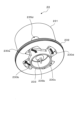
分離器20は、図2及び図9に示すように構成される。なお、図2は、分離器20の構造を示す分解斜視図であり、図9は、分離器20の断面を示す断面図である。
The
図2及び図9において、分離器20は、ヘッド部21と、ヘッド部21の下方に続き円筒状の内周面を有するケース体22とを有する。ケース体22の底部にはドレイントラップ26が設けられている。ヘッド部21の上部には上方を向いて開口する第1接続口部211が形成され、ヘッド部21の側周面には、相互に正対した位置関係にて第2接続口部212及び第3接続口部213が形成されている。ヘッド部21には、つば付きの円筒状のホルダ23が収容される一方、ケース体22内には、下方に向って徐々に広がるテーパー状の外周面を有するテーパー筒体24(気液分離部)が収容される。ヘッド部21とケース体22とは、ホルダ23とテーパー筒体24とが同軸的に結合されるように、2つのリング25a、25bを挟んでネジ締めにより一体化され、分離器20として構成される(図9参照)。
2 and 9, the
ホルダ23は、図3~図8に示すように構成される。なお、図3は、ホルダ23の斜め上方からみた構造を示す斜視図であり、図4は、ホルダ23の斜め下方から見た構造を示す斜視図であり、図5は、ホルダ23の構造(下から見た状態)を示す平面図である。図6は、ホルダ23の図5におけるA-A断面を示す断面図であり、図7は、ホルダ23の図5におけるC断面及びD断面を示す断面図であり、図8は、ホルダ23の図5におけるB断面及びE断面を示す断面図である。
The
図3~図8において、ホルダ23は、外円筒体231を有し、外円筒体231の下周縁にはフランジ232が形成されている。外円筒体231内には内ブロック233が当該外円筒体231のフランジ232の面から下方に部分的に突出するように設けられている。内ブロック233は、上部が閉鎖された円筒形状の本体部分を有し、その本体部分の周面から径方向に突出する4つ部分が外円筒体231の内周面に接合している。外円筒体231の内周面と内ブロック233との間には、上下方向に通ずる4つの流路230a、230b、230c、230d(回転誘導流路)が形成されている(図3、図4、図7参照)。各流路230a、230b、230c、230dには、上から下に傾く傾斜部が形成されている。外円筒体231の周面の所定位置には4つの開口235a、235b、235c、235dが形成されている。内ブロック233の円筒状の本体部分から径方向に突出する4つの部分のそれぞれには、外円筒体231に形成された4つの開口235a、235b、235c、235dのうちの1つに至る流路が形成されている。なお、図3には、外円筒体231の周面に形成された2つの開口235b、235cの位置が点線〇印で、また、図5には、外円筒体231の周面に形成された4つの開口235a、235b、235c、235dの位置が点線〇印で、それぞれ示されている。
3 to 8, the
図9において、ヘッド部21には、ホルダ23が、フランジ232が下側になる向きで、また、外円筒体231が第1接続口部211から続く通路と連通するように収容される。ヘッド部21において、ホルダ23を囲むようにリング状の気体送出し室215が形成されている。テーパー筒体24の小径となる上端部がホルダ23の内ブロック233に嵌った状態で、そのテーパー筒体24を収容するケース体22と、ホルダ23を収容するヘッド部21とが同軸的に結合される。この状態で、ヘッド部21から下方に突出するホルダ23のフランジ232の周面がO-リングを挟んでケース体22の内周面に密接し、ケース体22内の密閉状態が保持される。
In FIG. 9, the
上述した構造の分離器20では、ヘッド部21の第1接続口部211から流入する空気を、ホルダ23の外円筒体231内及び4つの流路230a、230b、230c、230d(回転誘導流路:図3、図4参照)を通して、ケース体22内に収容されたテーパー筒体24(気液分離部)の外面に導く流路が入り流路Pinとして形成される(図9における点線矢印参照)。また、テーパー筒体24の下端から当該テーパー筒体24の内部に形成される流路(第1流路)、テーパー筒体24の内部からホルダ23の内ブロック233内を通って外円筒体231の4つの開口235a、235b、235c、235dを通り、気体送出し室215に至る流路、気体送出し室215から第2接続口部212に続く流路(第2流路)、及び気体送出し室215から第3接続口部213に続く流路(第3流路)が出流路Poutとして形成される(二点鎖線矢印参照)。
In the
上述した構造の分離器20は、第1接続口部211が基管路11に接続されるとともに、第2接続口部212及び第3接続口部213が直列的にループ管路10に接続された状態で、圧縮空気圧回路100内に設けられる(図1参照)。このように圧縮空気圧回路100のループ管路10に接続された分離器20は、次のように動作する。
The
エアコンプレッサ30にて生成される圧縮空気がエアタンク32から基管路11を通して分離器20の第1接合口部211に流入する。以下、図9を参照するに、ヘッド部21の第1接続口部211から流入する圧縮空気は入り流路Pinを通って流れる(図9における点線矢印及び黒太矢印参照)。入り流路Pinを流れる圧縮空気は、ホルダ23の4つの流路230a、230b、230c、230d(回転誘導流路)を通る際に周方向の回転力が付与されて回転しながらケース体22内のテーパー筒体24の外周面上部に導かれる。ケース体22において、テーパー筒体24の外周面上部に導かれる圧縮空気はテーパー筒体24の外周面に沿って下降していく。テーパー筒体24の外周面とケース体22の内周面との間隔が下方にいくほど狭くなるので、テーパー筒体24の外周面に沿って下降する圧縮空気は徐々に速度を増しながらテーパー筒体24の外周面の周りを回転する。高速に回転する圧縮空気に作用する遠心力により、その圧縮空気から液分(凝縮液、油分等)が分離除去される。このように圧縮空気から分離除去された液分は、ケース体22の底部に設けられたドレイントラップ26に溜まる。
Compressed air generated by the
液分が分離除去された圧縮空気は、ケース体22におけるテーパー筒体24の最も広がった下端部から当該テーパー筒体24の内部(第1流路:出流路Pout)を通り、ヘッド部23におけるホルダ24の内ブロック233内を通って、外円筒体231の4つの開口235a、235b、235c、235dをぬけて気体送出し室215に至る。そして、その液分が分離除去された圧縮空気は、気体送出し室215から流路(第2流路:出流路Pout)を通って第2接続口部212から、また、気体送出し室215から流路(第3流路:出流路Pout)を通って第3接続口部213からループ管路10に流出する(二点鎖線矢印及び太矢印参照)。このようにして分離器20(第2接続口部212、第3接続口部213)からループ管路10に流出した圧縮空気は、ループ管路10を流れて各分配管路12、13、14を通して操作の行われる空圧機器(エアガン42、44、エアシリンダ41)に供給される。
The compressed air from which the liquid has been separated and removed passes through the inside of the tapered cylinder 24 (first flow path: outlet flow path Pout) from the widest lower end of the tapered
分離器20における第2接続口部212から流出する圧縮空気と第3接続口213から流出する圧縮空気との割合は、ループ管路10に接続される空圧機器での圧縮空気の利用分布に応じて決まり得る。
The ratio of compressed air flowing out of the
なお、ループ管路10から下方に延びる分配管路14に接続される分離器43は、分離器20(本発明に係る第1の実施の形態に係る分離器)において第2接続口部212及び第3接続口部213のいずれかが閉鎖された構造となっている。開放された接続口部(第2接続口部212または第3接続口部213のいずれか)にエアガン44に続く管路が接続されている。このような分離器43により、エアガン44には更に液分が除去された圧縮空気が供給され得る。
The
上述したような分離器20によれば、第1接続口部211から流入する圧縮空気から液分が除去され、その液分が除去された圧縮空気が第2接続口部212及び第3接続口部213からループ管路10に流入するようになるので、ループ管路10には液分の除去された圧縮空気が流れるようになる。そのため、ループ管路10内に液分が溜まることを抑制することができ、ループ管路10に接続すべき分離器の数を低減させることができる。
According to the
また、このような分離器20が接続されたループ管路10を有する圧縮空気圧回路100によれば、ループ管路10内に液分が溜まることが抑制されるとともに、ループ管路10に接続すべき複数(多く)の空圧機器(エアシリンダ41、エアガン42)それぞれに対して分離器を設ける必要がなく、ループ管路10に接続すべき分離器の数を低減させることができる。
In addition, a compressed
前述した分離器20では、ヘッド部21において、出流路Poutの気体送出し室215が、ホルダ23(入り流路Pin)の外側にリング状に形成されているので、出流路Poutの気体送出し室215と入り流路Pinとをヘッド部21内にスペースの無駄なく配置することができる。
In the
また、ホルダ23(4つの流路230a~230d:回転誘導流路)を通して圧縮空気を回転させながらテーパー筒体24の外周面上部に導くようにしているので、テーパー筒体24の外周面を空気がより高速に回転することができる。その結果、テーパー筒体24の外周面に沿って回転する空気から効果的に液分を除去することができる。
In addition, the compressed air is rotated through the holder 23 (four
なお、上述した圧縮空気圧回路100は、図1に示すものに限定されない。分離器20が接続されるループ管路10の形状や構造、また、ループ管路10に接続される空圧機器の数や種類は、種々変更することが可能である。また、基管路11を通して分離器20に圧縮空気を供給するための構成は、図1に示すものに限定されず、エアコンプレッサ30によって生成される圧縮空気を第1接続口部211を通して分離器20に供給できるものであればよい。
The compressed
次に、本発明の第2の実施の形態に係る分離器を図10に基づいて説明する。 Next, a separator according to a second embodiment of the present invention will be described with reference to FIG.
第2の実施の形態に係る分離器は、気液分離部の具体的な構造が異なる点で前述した第1の実施の形態のものと相違する。 The separator according to the second embodiment differs from that of the first embodiment described above in that the specific structure of the gas-liquid separation section is different.
図10において、この分離器60は、ヘッド部61と、ヘッド部61の下方に続き、円筒状の内周面を有するケース体62とを有している。ケース体62の底部にはドレイントラップ66が設けられている。ヘッド部61の上部には上方を向いて開口する第1接続口部611が形成され、ヘッド部61の側周面には、相互に正対した位置関係にて第2接続口部612及び第3接続口部613が形成されている。
In FIG. 10, the
ケース体62内には、気液分離部としての3つの回転誘導リング70と円筒体64とが収容されている。各回転誘導リング70は、通過する空気をケース体62の内周面に沿って回転するように誘導するもので、具体的には後述するように構成されている。円筒体64は、円筒状の外筒64aと外筒64aの内側に所定の隙間をもって同軸的に配置された円筒状の内筒64bとを有する二重構造となっている。内筒64bは、空気の透過が可能なメッシュ構造となっている。内筒64bの下端部分は、外筒64aの下端縁から突出しており、内筒64bの下端面が蓋体67で塞がれるとともに、外筒64aの下端縁と蓋体67との間に隙間が形成されている。3つの回転誘導リング体70と円筒体64とは、各回転誘導リング体70の中央空間と内筒64bとが連通するように、同軸的に結合された状態でケース体62に収容される。そして、ヘッド部61と、3つの回転誘導リング体70及び円筒体64を収容したケース体62とは結合固定され、分離器60として構成される。
The
前述した各回転誘導リング体70は、例えば、図11に示すように構成される。
Each of the rotation
図11において、回転誘導リング体70は、ケース体62の内径と略同一の外径となる外リング71と、所定径の内通孔75(中央空間)が形成された内リング72とを有している。外リング71と内リング72とは、それらの間に放射状に形成される複数(例えば、7つ)の連結部73a、73b、73c、73d、73e、73f、73gによって連結されている。また、外リング71と内リング72との間には、一の連結部(例えば、連結部73a)からそれに隣接する連結部(例えば、連結部73b)まで周方向に延び、当該回転誘導リング体70の上面(図12において表れてる面)から下面(図12において表れていない面)に向けて傾斜するガイド羽根74a、74b、74c、74d、74e、74f、74gが形成されている。この回転誘導リング体70においては、上面側から各ガイド羽根74a~74gに沿い、対応する連結部73a~73gをくぐって下面側にぬける空気の流路が形成されている。これにより、回転誘導リング体70の上面側から流入する圧縮空気は、当該回転誘導リング体70(外リング71、内リング72)の軸線のまわりに回転するようにして下面側にぬけ出るようになる。
11, the rotation
図10に戻って、ヘッド部61において、第1接続口部611から流入する空気をケース体62内に配置される回転誘導リング体70(外リング71と内リング72との間のガイド羽根74a~74g:気液分離部)に導く流路が入り流路Pinとして形成される(図12における点線矢印参照)。ヘッド部61では、入り流路Pinを囲むようにリング状の気体送出し室615が形成されている。また、円筒体64における外筒64aの下端縁と蓋体67との隙間から外筒64aと内筒64bとの間に入り、内筒65bを透過して内筒65bの内側を通って、3つの回転誘導リング体70の中央空間(内通孔75:図12参照)を通る流路(第1流路)、回転誘導リング体70の中央空間からヘッド部61内を通って気体送出し室615に至る流路、気体送出し室615から第2接続口部612に続く流路(第2流路)、及び気体送出し室615から第3接続口部613に続く流路(第3流路)が出流路Poutとして形成されている(二点鎖線矢印参照)。
Returning to Figure 10, in the
上述した構造の分離器60は、第1の実施の形態のものと同様に、第1接続口部611が基管路11に接続されるとともに、第2接続口部612及び第3接続口部613が直列的にループ管路10に接続された状態で、圧縮空気圧回路100内に設けられる(図1参照)。
The
ループ管路10に接続された分離器60では、ヘッド部61の第1接続口部611から流入する圧縮空気は入り流路Pinを通って流れる(図10における点線矢印及び黒太矢印参照)。入り流路Pinを流れる圧縮空気は、ヘッド部61の下方に続くケース体62において、3つの回転誘導リング体70によって回転しながら、円筒体64(外筒64a)の外周面に誘導される。そして、圧縮空気は、円筒体65(外筒64a)の外周面を高速に回転しながら徐々に下方に向って進み、その過程で、遠心力によりその圧縮空気から液分(凝縮液、油分等)が分離除去される。このように液分が分離除去された圧縮空気は、ケース体62の底部に設けられたドレイントラップ66に溜まる。
In the
液分が分離除去された圧縮空気は、円筒体64における外筒64aの下端縁と蓋体67との隙間から外筒64aと内筒64bとの間に入り、内筒65bを透過して内筒65bの内側、更に、3つの回転誘導リング体70の中央空間(内通孔75:図12参照)を通って(第1流路:出流路Pout)ヘッド部61における気体送出し室615に至る。そして、その液分が分離除去された圧縮空気は、気体送出し室615から流路(第2流路:出流路Pout)を通って第2接続口部612から、また、気体送出し室615から流路(第3流路:出流路Pout)を通って第3接続口部613からループ管路10に流出する(二点鎖線矢印及び太矢印参照)。
The compressed air from which the liquid has been separated and removed enters the gap between the
上述したような本発明の第3の実施の形態に係る分離器60によれば、第1の実施の形態に係る分離器20と同様に、第1接続口部611から流入する圧縮空気から液分が分離除去され、その液分が分離除去された圧縮空気が第2接続口部612及び第3接続口部613からループ管路10に流入するようになるので、ループ管路10には液分の除去された空気が流れるようになる。そのため、ループ管路10内に液分が溜まることを抑制することができ、ループ管路10に接続させるべき分離器の数を低減させることができる。
According to the
なお、上述した分離器60では、3つの回転誘導リング体70が設けられていたが、回転誘導リング体70の数は3つに限定されず、1つまたは2つであっても、あるいは4つ以上であってもよい。また、回転誘導リング体70の構成も図12に示すものに限定されず、ケース体62の円筒状の内周面と同軸的に配置され、通過する空気をケース体62の内周面に沿って回転するように誘導する構造のものであればよい。
In the
また、円筒体64は、二重構造ではなく外筒64aの単体であっても、また、第1の実施の形態のものと同様に、テーパー形状のものであってもよい。
In addition, the
以上、本発明の実施の形態を説明したが、各実施の形態は、一例として提示したものであり、発明の範囲を限定することは意図していない。上述したこれら新規な実施の形態は、その他の様々な形態で実施されることが可能であり、発明の要旨を逸脱しない範囲で、種々の省略、置き換え、変更を行うことができる。これら実施の形態は、発明の範囲や要旨に含まれるとともに、特許請求の範囲に記載された発明に含まれる。 Although the embodiments of the present invention have been described above, each embodiment is presented as an example and is not intended to limit the scope of the invention. These novel embodiments described above can be embodied in various other forms, and various omissions, substitutions, and modifications can be made without departing from the gist of the invention. These embodiments are included in the scope and gist of the invention, and are included in the invention described in the claims.
以上、説明したように、本発明に係る分離器は、ループ管路内に液分が溜まることを抑制して、ループ管路に接続すべき分離器の数を低減させることができるという効果を有し、ループ管路内に設けられ、内部を通過する空気流から液分を除去する分離器として有用である。 As described above, the separator according to the present invention has the effect of suppressing the accumulation of liquid in the loop pipe and reducing the number of separators that need to be connected to the loop pipe, and is useful as a separator that is installed in a loop pipe and removes liquid from the air flow passing through it.
10 ループ管路
11 基管路
12、13、14 分配管路
20、60 分離器(セパレータ)
21、61 ヘッド部
211、611 第1接続口部
212、612 第2接続口部
213、613 第3接続口部
215、615 気体送出し室
22、62 ケース体
23 ホルダ
231 外円筒体
232 フランジ
233 内ブロック
230a、230b、230c、230d 流路
235a、235b、235c、235d 開口
24 テーパー筒体
25a、25b リング
26、56、66 ドレイントラップ
30 エアコンプレッサ
31 エアドライヤ
32 エアタンク
33、34 セパレータ
35 フィルタ
41 エアシリンダ
42、44 エアガン
43 分離器
64 円筒体
64a 外筒
64b 内筒
70 回転誘導リング体
75 内通孔
100 圧縮空気圧回路
10
Claims (5)
空気が流入する第1接続口部と、
前記ループ管路に直列的に接続される第2接続口部及び第3接続口部と、
流入する空気から液分を除去する気液分離部と、
前記第1接続口部から流入する空気を前記気液分離部に導く入り流路と、
前記気液分離部により液分が除去された空気を前記第2接続口部及び前記第3接続口部のそれぞれに導く出流路と、を有し、
更に、ヘッド部と、
前記ヘッド部から下方に続き、円筒状の内周面を有するケース体と、を有し、
前記第1接続口部、前記第2接続口部、及び前記第3接続口部は、前記ヘッド部に設けられ、
前記気液分離部は、前記ケース体内に、当該ケース体の円筒状の内周面と同軸的に配置され、下方に向かって徐々に広がるテーパー状の外周面を有するテーパー筒体を有し、
前記入り流路は、前記ヘッド部内において、前記第1接続口部から流入する空気を前記ケース体内に配置された前記テーパー筒体の外周面に導く流路として形成され、
前記出流路は、
前記テーパー筒体の内部を通る第1流路と、
前記第1流路に連通し、前記ヘッド部内に形成された気体送出し室と、
前記気体送出し室から前記第2接続口部に続く第2流路と、
前記気体送出し室から前記第3接続口部に続く第3流路と、を有する分離器。 A separator provided in a loop pipe through which compressed air flows, for removing liquid from an air flow passing therethrough,
A first connection port through which air flows in;
A second connection port and a third connection port connected in series to the loop pipe;
A gas-liquid separator that removes liquid from the incoming air;
an inlet flow path that guides air flowing in from the first connection port to the gas-liquid separation section;
an outlet flow path that guides the air from which the liquid has been removed by the gas-liquid separator to each of the second connection port and the third connection port ,
Further, a head portion and
a case body extending downward from the head portion and having a cylindrical inner circumferential surface;
the first connection port, the second connection port, and the third connection port are provided on the head portion,
the gas-liquid separation unit includes a tapered cylinder disposed within the case body coaxially with a cylindrical inner circumferential surface of the case body and having a tapered outer circumferential surface that gradually widens downward;
The inlet flow passage is formed in the head portion as a flow passage that guides the air flowing in from the first connection port portion to an outer circumferential surface of the tapered cylinder disposed in the case body,
The outlet flow path is
A first flow path passing through the inside of the tapered cylinder;
a gas delivery chamber formed in the head portion and communicating with the first flow path;
a second flow passage leading from the gas delivery chamber to the second connection port;
a third flow path extending from the gas delivery chamber to the third connection port .
空気が流入する第1接続口部と、
前記ループ管路に直列的に接続される第2接続口部及び第3接続口部と、
流入する空気から液分を除去する気液分離部と、
前記第1接続口部から流入する空気を前記気液分離部に導く入り流路と、
前記気液分離部により液分が除去された空気を前記第2接続口部及び前記第3接続口部のそれぞれに導く出流路と、を有し、
更に、ヘッド部と、
前記ヘッド部から下方に続き、円筒状の内周面を有するケース体と、を有し、
前記第1接続口部、前記第2接続口部、及び前記第3接続口部は、前記ヘッド部に設けられ、
前記気液分離部は、
前記ケース体内に設けられ、当該ケース体の円筒状の内周面と同軸的に配置され、通過する空気を前記ケース体の内周面に沿って回転するように誘導する回転誘導リング体と、
前記回転誘導リング体の下方に当該回転誘導リング体と同軸的に配置される円筒体と、
を有し、
前記入り流路は、前記ヘッド部内において、前記第1接続口から流入する空気を前記ケース体内に配置された回転誘導リング体に導く流路として形成され、
前記出流路は、
前記円筒体の内部及び前記回転誘導リング体の中央空間を含む第1流路と、
前記第1流路に続き、前記ヘッド部内に形成された気体送出し室と、
前記気体送出し室から前記第2接続口部に続く第2流路と、
前記気体送出し室から前記第3 接続口部に続く第3流路と、を有する分離器。 A separator provided in a loop pipe through which compressed air flows, for removing liquid from an air flow passing therethrough,
A first connection port through which air flows in ;
A second connection port and a third connection port connected in series to the loop pipe;
A gas-liquid separator that removes liquid from the incoming air;
an inlet flow path that guides air flowing in from the first connection port to the gas-liquid separation section ;
an outlet flow path that guides the air from which the liquid has been removed by the gas-liquid separator to each of the second connection port and the third connection port,
Further, a head portion and
a case body extending downward from the head portion and having a cylindrical inner circumferential surface;
the first connection port, the second connection port, and the third connection port are provided on the head portion,
The gas-liquid separation section is
a rotation guide ring body provided within the case body, arranged coaxially with a cylindrical inner peripheral surface of the case body, and configured to guide air passing through the case body so as to rotate along the inner peripheral surface of the case body;
a cylindrical body arranged below the rotation guide ring body and coaxially with the rotation guide ring body;
having
The inlet flow passage is formed in the head portion as a flow passage that guides the air flowing in from the first connection port to a rotation guide ring body disposed in the case body,
The outlet flow path is
A first flow path including an interior of the cylindrical body and a central space of the rotation guide ring body;
a gas delivery chamber formed in the head portion and connected to the first flow path;
a second flow passage leading from the gas delivery chamber to the second connection port;
a third flow path extending from the gas delivery chamber to the third connection port.
請求項1または3に記載された分離器を備え、
前記分離器の前記第1接続口部に圧縮空気が供給され、
前記分離器の前記第2接続口部及び前記第3接続口部が直列的に前記ループ管路に接続された、圧縮空気圧回路。
A compressed air pressure line including a circular loop line to which compressed air is supplied and a distribution line for distributing the compressed air from the loop line to an apparatus,
A separator according to claim 1 or 3 ,
Compressed air is supplied to the first connection port of the separator,
a compressed air pressure circuit, the second connection port and the third connection port of the separator being connected in series to the loop pipe.
Priority Applications (1)
| Application Number | Priority Date | Filing Date | Title |
|---|---|---|---|
| JP2022125474A JP7572011B2 (en) | 2022-08-05 | 2022-08-05 | Separator and compressed air circuit using same |
Applications Claiming Priority (1)
| Application Number | Priority Date | Filing Date | Title |
|---|---|---|---|
| JP2022125474A JP7572011B2 (en) | 2022-08-05 | 2022-08-05 | Separator and compressed air circuit using same |
Publications (2)
| Publication Number | Publication Date |
|---|---|
| JP2024022114A JP2024022114A (en) | 2024-02-16 |
| JP7572011B2 true JP7572011B2 (en) | 2024-10-23 |
Family
ID=89854761
Family Applications (1)
| Application Number | Title | Priority Date | Filing Date |
|---|---|---|---|
| JP2022125474A Active JP7572011B2 (en) | 2022-08-05 | 2022-08-05 | Separator and compressed air circuit using same |
Country Status (1)
| Country | Link |
|---|---|
| JP (1) | JP7572011B2 (en) |
Families Citing this family (1)
| Publication number | Priority date | Publication date | Assignee | Title |
|---|---|---|---|---|
| JP7680094B1 (en) * | 2024-07-19 | 2025-05-20 | 株式会社フクハラ | Air dryer with built-in steam separator |
Citations (4)
| Publication number | Priority date | Publication date | Assignee | Title |
|---|---|---|---|---|
| JP2015182075A (en) | 2014-03-24 | 2015-10-22 | 東プレ株式会社 | Gas-liquid separator |
| JP2015217326A (en) | 2014-05-15 | 2015-12-07 | 吉雄 網本 | Cyclone gas-liquid separator with improved gas-liquid separation efficiency |
| JP2016087507A (en) | 2014-10-31 | 2016-05-23 | 株式会社フクハラ | Air filter and compression pneumatic circuit using the same |
| JP2022093999A (en) | 2020-12-14 | 2022-06-24 | 株式会社フクハラ | Separator and compressed pneumatic circuit using the same |
-
2022
- 2022-08-05 JP JP2022125474A patent/JP7572011B2/en active Active
Patent Citations (4)
| Publication number | Priority date | Publication date | Assignee | Title |
|---|---|---|---|---|
| JP2015182075A (en) | 2014-03-24 | 2015-10-22 | 東プレ株式会社 | Gas-liquid separator |
| JP2015217326A (en) | 2014-05-15 | 2015-12-07 | 吉雄 網本 | Cyclone gas-liquid separator with improved gas-liquid separation efficiency |
| JP2016087507A (en) | 2014-10-31 | 2016-05-23 | 株式会社フクハラ | Air filter and compression pneumatic circuit using the same |
| JP2022093999A (en) | 2020-12-14 | 2022-06-24 | 株式会社フクハラ | Separator and compressed pneumatic circuit using the same |
Also Published As
| Publication number | Publication date |
|---|---|
| JP2024022114A (en) | 2024-02-16 |
Similar Documents
| Publication | Publication Date | Title |
|---|---|---|
| KR102014008B1 (en) | Centrifuges for Gas Cleaning | |
| JP3223159U (en) | Essential oil atomizer | |
| US8821362B2 (en) | Multiple modular in-line rotary separator bundle | |
| KR100834953B1 (en) | Drain separator | |
| JP5667651B2 (en) | Mist separator | |
| CA2432821A1 (en) | Oil separator for a welder | |
| CN1620338A (en) | Apparatus for simultaneous cleaning of a liquid and a gas | |
| JP7572011B2 (en) | Separator and compressed air circuit using same | |
| KR960001378B1 (en) | Oil filter | |
| JP7392949B2 (en) | Separator and compressed air pressure circuit using it | |
| JP2013128894A (en) | Gas-liquid separator | |
| JP5774327B2 (en) | Gas-liquid separator | |
| JPS60147502A (en) | Gas-liquid separation apparatus and its adaptation for removing oil from compressed air in turbine engine bearing case | |
| JP7406261B2 (en) | gas filter device | |
| CN109999591A (en) | Combined type gas and water separator | |
| EP4272871A1 (en) | A centrifugal separator comprising a turbine casing | |
| JP2005000864A (en) | Gas-liquid separator | |
| JP5649919B2 (en) | Gas-liquid separator | |
| KR100780839B1 (en) | Compressor Filter | |
| RU2659988C1 (en) | Gas-dynamic vortex separator (options) | |
| JP2020157191A (en) | Air bubble separation/removal device | |
| JP2012061415A (en) | Gas-liquid separator | |
| TWM679380U (en) | Supergravity device | |
| KR20060063069A (en) | Oil separator in blow-by gas of cylinder head | |
| JP2007283196A (en) | Gas-liquid separator |
Legal Events
| Date | Code | Title | Description |
|---|---|---|---|
| A621 | Written request for application examination |
Free format text: JAPANESE INTERMEDIATE CODE: A621 Effective date: 20231019 |
|
| A977 | Report on retrieval |
Free format text: JAPANESE INTERMEDIATE CODE: A971007 Effective date: 20240625 |
|
| A131 | Notification of reasons for refusal |
Free format text: JAPANESE INTERMEDIATE CODE: A131 Effective date: 20240703 |
|
| A521 | Request for written amendment filed |
Free format text: JAPANESE INTERMEDIATE CODE: A523 Effective date: 20240716 |
|
| TRDD | Decision of grant or rejection written | ||
| A01 | Written decision to grant a patent or to grant a registration (utility model) |
Free format text: JAPANESE INTERMEDIATE CODE: A01 Effective date: 20241002 |
|
| A61 | First payment of annual fees (during grant procedure) |
Free format text: JAPANESE INTERMEDIATE CODE: A61 Effective date: 20241002 |
|
| R150 | Certificate of patent or registration of utility model |
Ref document number: 7572011 Country of ref document: JP Free format text: JAPANESE INTERMEDIATE CODE: R150 |