JP5774327B2 - Gas-liquid separator - Google Patents
Gas-liquid separator Download PDFInfo
- Publication number
- JP5774327B2 JP5774327B2 JP2011031413A JP2011031413A JP5774327B2 JP 5774327 B2 JP5774327 B2 JP 5774327B2 JP 2011031413 A JP2011031413 A JP 2011031413A JP 2011031413 A JP2011031413 A JP 2011031413A JP 5774327 B2 JP5774327 B2 JP 5774327B2
- Authority
- JP
- Japan
- Prior art keywords
- liquid
- exhaust pipe
- plug
- chamber
- casing
- Prior art date
- Legal status (The legal status is an assumption and is not a legal conclusion. Google has not performed a legal analysis and makes no representation as to the accuracy of the status listed.)
- Active
Links
Images
Description
本発明は、蒸気や圧縮空気や各種ガス等の気体中に混入している復水や凝縮水等の液体をケーシング内に旋回流を起こし遠心力によって分離する気液分離器に関し、特にケーシング内に流体をろ過するフィルターを配置したものに関する。 The present invention relates to a gas-liquid separator that generates a swirling flow in a casing and separates the liquid such as condensate or condensed water mixed in a gas such as steam, compressed air, or various gases by centrifugal force, and particularly in the casing. And a filter for filtering fluid.
従来の気液分離器は、例えば特許文献1に開示されている。これは、ケーシングと排気管で形成する環状空間に旋回羽根を配置し、旋回羽根の上方を入口に連結し、排気管の内側の孔を通してその上方を出口に連結し、環状空間の下方に旋回室と該旋回室の下方に液溜室を形成して該液溜室の下部を排液口に連結し、排気管と液溜室の間に下端部にプラグを設けた流体ろ過用の円筒状フィルターを配置し、旋回室と液溜室の間に外側のケーシング内周壁との間に液体通過用の隙間を設けた隔壁部材を配置したものである。
A conventional gas-liquid separator is disclosed in
上記従来の気液分離器においては、分離された液体が再び気体流に巻き込まれて出口に運び出されてしまうために気液の分離効率が悪い問題点があった。これは、旋回室の中央よりを旋回して円筒状フィルター内に流入した微少な液体が液溜室に流入できないためである。 The conventional gas-liquid separator has a problem that the separation efficiency of gas-liquid is poor because the separated liquid is re-entrained in the gas flow and carried to the outlet. This is because the minute liquid swirling from the center of the swirl chamber and flowing into the cylindrical filter cannot flow into the liquid reservoir chamber.
したがって本発明が解決しようとする課題は、分離された液体が液溜室に流入し易くして気液の分離効率の良い気液分離器を提供することである。 Therefore, the problem to be solved by the present invention is to provide a gas-liquid separator having a high gas-liquid separation efficiency by allowing the separated liquid to easily flow into the liquid storage chamber.
上記の課題を解決するために、本発明の気液分離器は、ケーシングと排気管で形成する環状空間に旋回羽根を配置し、旋回羽根の上方を入口に連結し、排気管の内側の孔を通してその上方を出口に連結し、環状空間の下方に旋回室と該旋回室の下方に液溜室を形成して該液溜室の下部を排液口に連結し、排気管と液溜室の間に下端部にプラグを設けた流体ろ過用の円筒状フィルターを配置したものにおいて、プラグの外周壁とケーシングの内周壁との間に外側のケーシング内周壁との間に液体通過用の隙間を設けた隔壁部材を配置し、円筒状フィルター内と液溜室を連通する液体通過用の連通孔をプラグに設けたことを特徴とするものである。 In order to solve the above problems, the gas-liquid separator of the present invention has a swirl vane disposed in an annular space formed by a casing and an exhaust pipe, and the upper part of the swirl vane is connected to an inlet, and a hole inside the exhaust pipe. The upper part is connected to the outlet, a swirl chamber is formed below the annular space, a liquid reservoir chamber is formed below the swirl chamber, and the lower part of the liquid reservoir is connected to the drain port, and the exhaust pipe and the liquid reservoir chamber A fluid filtering cylindrical filter having a plug at the lower end is disposed between the outer peripheral wall of the plug and the inner peripheral wall of the casing. A partition member provided with a liquid crystal is disposed, and a communication hole for liquid passage that communicates the inside of the cylindrical filter and the liquid storage chamber is provided in the plug.
本発明によれば、プラグの外周壁とケーシングの内周壁との間に外側のケーシング内周壁との間に液体通過用の隙間を設けた隔壁部材を配置し、円筒状フィルター内と液溜室を連通する液体通過用の連通孔をプラグに設けたことにより、旋回室の中央よりを旋回して円筒状フィルター内に流入した微少な液体が連通孔を通して液溜室に流下するので、分離された液体が液溜室に流入し易くなるという効果を奏する。 According to the present invention, the partition member having the liquid passage gap between the outer peripheral wall of the plug and the inner peripheral wall of the casing is disposed between the outer peripheral wall of the casing and the inner peripheral wall of the casing. Since the plug has a communication hole for passing the liquid, the small liquid swirling from the center of the swirl chamber and flowing into the cylindrical filter flows down to the liquid storage chamber through the communication hole. This has the effect of allowing the liquid to easily flow into the liquid storage chamber.
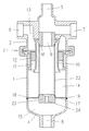
以下、本発明の実施の形態について、図1を参照して説明する。ケーシングは円筒状本体1と出入口部材2をクランプ継手3で結合し、本体1の下部に底蓋4を溶接により結合して形成する。出入口部材2には左右同軸上に入口6と出口7を設け、上端中央にプラグ孔5を設ける。プラグ孔5は逆洗用の流体配管を接続したり圧力計を接続したりするために使用する。底蓋4には下端中央に排液口8を設ける。出入口部材2に連通口9を開けた弁座16をネジ結合する。出入口部材2と弁座16の間には排気管10の上端の内向きフランジを間に挟むことにより、排気管10を出入口部材2に固定する。排気管10は二重のほぼ円筒形状で、内側円筒の上下端部を末広がりに形成する。排気管10の外側円筒は省略して本体1で兼用することもできる。排気管10の内外円筒の間に形成される環状空間11に、排気管10と一体に旋回羽根12を形成する。
Hereinafter, an embodiment of the present invention will be described with reference to FIG. The casing is formed by connecting the cylindrical
入口6は連通孔13を通して下方の環状空間11に連結し、排気管10の内側は弁座16の連通口9を介して上方の出口7に連結する。本体1の下部内面と底蓋4の内面との間に旋回室14と、この旋回室14の下方に液溜室15を形成し、液溜室15の下端を排液口8に連結する。旋回室14と排気管10の内側に長尺円筒状の中空フィルター22を配置する。フィルター22は上端を弁座16に溶接により固定し、下端部にプラグ23を溶接により固定する。フィルター22は多数の微細な貫通孔を有し、入口6と環状空間11を流下してきた流体からゴミやスケール等の異物を捕捉して流体を出口7側へ排出するものである。フィルター22のろ過粒度は0.5マイクロから10マイクロ程度が好適である。フィルター22は全長の約半分が排気管10内に位置し、残りの約半分が旋回室14内に位置する。
The
プラグ23の外周壁と本体1の内周壁との間に隔壁部材17を配置する。隔壁部材17はリング形状で内周をプラグ23に溶接により固定する。隔壁部材17は外周に4個の突起18を有し、突起18の間の隔壁部材17外周縁と本体1内周壁との間に液体通過用隙間19を形成する。プラグ23はフィルター22内と液溜室15を連通する液体通過用の連通孔24を有する。
A
上記の気液分離器の動作は次の通りである。入口6から入った液体やゴミやスケール等の異物を含む気体は旋回羽根12で旋回される。質量の大きな液体や粒度の大きな異物は遠心力の作用で外側に振り出されて分離され、本体1の内周壁に沿って流下し、液体通過用隙間19を通して液溜室15に流入して排液口8から系外に排出される。旋回室14の中央よりを旋回してフィルター22内に流入した微少な液体は連通孔24を通して液溜室15に流入して排液口8から系外に排出される。
The operation of the gas-liquid separator is as follows. A gas containing foreign matter such as liquid, dust or scale entering from the
旋回室14の中央よりを旋回してフィルター22内に流入した微少な液体は連通孔24を通して液溜室15に流入するので、分離された液体が液溜室15に流入し易くなり、気液の分離効率が良くなる。
Since the minute liquid swirling from the center of the
本発明は、気体中に混入している液体をケーシング内に旋回流を起こし遠心力によって分離すると共にケーシング内に流体をろ過するフィルターを配置したあらゆる種類の気液分離器に利用することができる。 INDUSTRIAL APPLICABILITY The present invention can be used for all types of gas-liquid separators in which a liquid that is mixed in gas is swirled in the casing and separated by centrifugal force and a filter for filtering the fluid is disposed in the casing. .
1 本体
2 出入口部材
3 クランプ継手
4 底蓋
5 プラグ孔
6 入口
7 出口
8 排液口
9 連通口
10 排気管
11 環状空間
12 旋回羽根
13 連通孔
14 旋回室
15 液溜室
16 弁座
17 隔壁部材
18 突起
19 液体通過用隙間
22 フィルター
23 プラグ
24 連通孔
DESCRIPTION OF
Claims (1)
Priority Applications (1)
| Application Number | Priority Date | Filing Date | Title |
|---|---|---|---|
| JP2011031413A JP5774327B2 (en) | 2011-02-16 | 2011-02-16 | Gas-liquid separator |
Applications Claiming Priority (1)
| Application Number | Priority Date | Filing Date | Title |
|---|---|---|---|
| JP2011031413A JP5774327B2 (en) | 2011-02-16 | 2011-02-16 | Gas-liquid separator |
Publications (2)
| Publication Number | Publication Date |
|---|---|
| JP2012166176A JP2012166176A (en) | 2012-09-06 |
| JP5774327B2 true JP5774327B2 (en) | 2015-09-09 |
Family
ID=46970876
Family Applications (1)
| Application Number | Title | Priority Date | Filing Date |
|---|---|---|---|
| JP2011031413A Active JP5774327B2 (en) | 2011-02-16 | 2011-02-16 | Gas-liquid separator |
Country Status (1)
| Country | Link |
|---|---|
| JP (1) | JP5774327B2 (en) |
Families Citing this family (4)
| Publication number | Priority date | Publication date | Assignee | Title |
|---|---|---|---|---|
| JP2013163143A (en) * | 2012-02-09 | 2013-08-22 | Idemitsu Kosan Co Ltd | Cyclone separator |
| US9645651B2 (en) | 2013-09-24 | 2017-05-09 | Microsoft Technology Licensing, Llc | Presentation of a control interface on a touch-enabled device based on a motion or absence thereof |
| US9594489B2 (en) | 2014-08-12 | 2017-03-14 | Microsoft Technology Licensing, Llc | Hover-based interaction with rendered content |
| CN115802956A (en) | 2020-07-22 | 2023-03-14 | 京瓷株式会社 | Water trap, smoke exhaust pipe group and operation system |
Family Cites Families (5)
| Publication number | Priority date | Publication date | Assignee | Title |
|---|---|---|---|---|
| JPH0699012A (en) * | 1992-09-21 | 1994-04-12 | Taiyo Kiko:Kk | Air purifier |
| JPH0660417U (en) * | 1993-02-02 | 1994-08-23 | 有限会社太陽機工 | Drain removal device |
| JPH11267434A (en) * | 1998-03-26 | 1999-10-05 | Ckd Corp | Vacuum filter |
| JP2004340452A (en) * | 2003-05-15 | 2004-12-02 | Tlv Co Ltd | Gas-liquid separator |
| JP5384441B2 (en) * | 2010-07-15 | 2014-01-08 | 株式会社テイエルブイ | Gas-liquid separator |
-
2011
- 2011-02-16 JP JP2011031413A patent/JP5774327B2/en active Active
Also Published As
| Publication number | Publication date |
|---|---|
| JP2012166176A (en) | 2012-09-06 |
Similar Documents
| Publication | Publication Date | Title |
|---|---|---|
| JP6032943B2 (en) | Gas-liquid separator | |
| JP5253975B2 (en) | Steam separator | |
| JP5774327B2 (en) | Gas-liquid separator | |
| JP5350280B2 (en) | Gas-liquid separator | |
| JP2013128894A (en) | Gas-liquid separator | |
| JP2004340452A (en) | Gas-liquid separator | |
| JP5791384B2 (en) | Gas-liquid separator | |
| JP5547009B2 (en) | Gas-liquid separator | |
| JP5868714B2 (en) | Gas-liquid separator | |
| JP5561996B2 (en) | Gas-liquid separator | |
| JP5384441B2 (en) | Gas-liquid separator | |
| JP5476000B2 (en) | Gas-liquid separator | |
| JP5112644B2 (en) | Steam separator | |
| JP5384420B2 (en) | Gas-liquid separator | |
| JP5489564B2 (en) | Gas-liquid separator | |
| JP5649919B2 (en) | Gas-liquid separator | |
| JP5791345B2 (en) | Gas-liquid separator | |
| JP5754809B2 (en) | Gas-liquid separator | |
| JP5667409B2 (en) | Gas-liquid separator | |
| JP5350289B2 (en) | Gas-liquid separator | |
| JP4865393B2 (en) | Steam separator | |
| JP4489376B2 (en) | Gas-liquid separator | |
| JP2010162479A (en) | Gas-liquid separator | |
| JP5715812B2 (en) | Gas-liquid separator | |
| JP5881407B2 (en) | Gas-liquid separator |
Legal Events
| Date | Code | Title | Description |
|---|---|---|---|
| A621 | Written request for application examination |
Free format text: JAPANESE INTERMEDIATE CODE: A621 Effective date: 20140207 |
|
| A131 | Notification of reasons for refusal |
Free format text: JAPANESE INTERMEDIATE CODE: A131 Effective date: 20150414 |
|
| A521 | Request for written amendment filed |
Free format text: JAPANESE INTERMEDIATE CODE: A523 Effective date: 20150611 |
|
| TRDD | Decision of grant or rejection written | ||
| A01 | Written decision to grant a patent or to grant a registration (utility model) |
Free format text: JAPANESE INTERMEDIATE CODE: A01 Effective date: 20150630 |
|
| A61 | First payment of annual fees (during grant procedure) |
Free format text: JAPANESE INTERMEDIATE CODE: A61 Effective date: 20150701 |
|
| R150 | Certificate of patent or registration of utility model |
Ref document number: 5774327 Country of ref document: JP Free format text: JAPANESE INTERMEDIATE CODE: R150 |