JP7569737B2 - Air conditioning equipment - Google Patents
Air conditioning equipment Download PDFInfo
- Publication number
- JP7569737B2 JP7569737B2 JP2021063108A JP2021063108A JP7569737B2 JP 7569737 B2 JP7569737 B2 JP 7569737B2 JP 2021063108 A JP2021063108 A JP 2021063108A JP 2021063108 A JP2021063108 A JP 2021063108A JP 7569737 B2 JP7569737 B2 JP 7569737B2
- Authority
- JP
- Japan
- Prior art keywords
- heat
- heating
- heat medium
- temperature
- air conditioning
- Prior art date
- Legal status (The legal status is an assumption and is not a legal conclusion. Google has not performed a legal analysis and makes no representation as to the accuracy of the status listed.)
- Active
Links
- 238000004378 air conditioning Methods 0.000 title claims description 41
- 238000010438 heat treatment Methods 0.000 claims description 193
- XLYOFNOQVPJJNP-UHFFFAOYSA-N water Substances O XLYOFNOQVPJJNP-UHFFFAOYSA-N 0.000 description 37
- 238000011144 upstream manufacturing Methods 0.000 description 11
- 238000000034 method Methods 0.000 description 10
- 230000008569 process Effects 0.000 description 10
- 239000003507 refrigerant Substances 0.000 description 10
- 238000004891 communication Methods 0.000 description 9
- 238000002485 combustion reaction Methods 0.000 description 7
- 238000012545 processing Methods 0.000 description 7
- 238000005516 engineering process Methods 0.000 description 4
- 230000007246 mechanism Effects 0.000 description 3
- 230000009467 reduction Effects 0.000 description 3
- 238000012546 transfer Methods 0.000 description 3
- 238000012937 correction Methods 0.000 description 2
- 238000010586 diagram Methods 0.000 description 2
- 239000012071 phase Substances 0.000 description 2
- 108010053481 Antifreeze Proteins Proteins 0.000 description 1
- 230000002528 anti-freeze Effects 0.000 description 1
- 230000003247 decreasing effect Effects 0.000 description 1
- 238000005265 energy consumption Methods 0.000 description 1
- 239000000446 fuel Substances 0.000 description 1
- 230000006870 function Effects 0.000 description 1
- 239000007791 liquid phase Substances 0.000 description 1
- 238000012986 modification Methods 0.000 description 1
- 230000004048 modification Effects 0.000 description 1
- 230000002265 prevention Effects 0.000 description 1
Images


Classifications
-
- Y—GENERAL TAGGING OF NEW TECHNOLOGICAL DEVELOPMENTS; GENERAL TAGGING OF CROSS-SECTIONAL TECHNOLOGIES SPANNING OVER SEVERAL SECTIONS OF THE IPC; TECHNICAL SUBJECTS COVERED BY FORMER USPC CROSS-REFERENCE ART COLLECTIONS [XRACs] AND DIGESTS
- Y02—TECHNOLOGIES OR APPLICATIONS FOR MITIGATION OR ADAPTATION AGAINST CLIMATE CHANGE
- Y02B—CLIMATE CHANGE MITIGATION TECHNOLOGIES RELATED TO BUILDINGS, e.g. HOUSING, HOUSE APPLIANCES OR RELATED END-USER APPLICATIONS
- Y02B30/00—Energy efficient heating, ventilation or air conditioning [HVAC]
- Y02B30/70—Efficient control or regulation technologies, e.g. for control of refrigerant flow, motor or heating
Landscapes
- Steam Or Hot-Water Central Heating Systems (AREA)
Description
本明細書で開示する技術は、空調装置に関する。 The technology disclosed in this specification relates to air conditioning devices.
特許文献1に空調装置が開示されている。特許文献1の空調装置は、熱媒の熱により室内を空調するファンコンベクタと、ファンコンベクタに供給する熱媒を加熱する熱源機とを備えている。 Patent document 1 discloses an air conditioner. The air conditioner in Patent document 1 includes a fan convector that uses heat from a heat medium to condition the interior of a room, and a heat source unit that heats the heat medium supplied to the fan convector.
特許文献1の空調装置では、ファンコンベクタのファンの回転数を制御することがある。例えば、熱源機からファンコンベクタに供給される熱媒の温度が低い場合に、ファンコンベクタから室内に供給される熱量を一定に維持するために、ファンコンベクタのファンの回転数を大きくすることがある。また、熱源機からファンコンベクタに供給される熱媒の温度が高い場合に、ファンコンベクタから室内に供給される熱量を一定に維持するために、ファンコンベクタのファンの回転数を小さくすることがある。この構成では、熱源機からファンコンベクタに供給される熱媒の温度によってファンコンベクタのファンの回転数が大きく変動することがある。一方、ファンの回転数の変動を抑制しようとすると、ファンコンベクタから室内に適切な熱量を供給できなくなることがある。そうすると、室内を適切な温度に空調することができなくなる。そこで本明細書では、空調端末のファンの回転数が大きく変動することを抑制することができると共に、適切な熱量で室内を空調することができる技術を提供する。 In the air conditioner of Patent Document 1, the rotation speed of the fan of the fan convector may be controlled. For example, when the temperature of the heat medium supplied from the heat source unit to the fan convector is low, the rotation speed of the fan of the fan convector may be increased in order to maintain a constant amount of heat supplied from the fan convector to the room. Also, when the temperature of the heat medium supplied from the heat source unit to the fan convector is high, the rotation speed of the fan of the fan convector may be decreased in order to maintain a constant amount of heat supplied from the fan convector to the room. In this configuration, the rotation speed of the fan convector may vary greatly depending on the temperature of the heat medium supplied from the heat source unit to the fan convector. On the other hand, if an attempt is made to suppress the fluctuation in the fan rotation speed, it may not be possible to supply an appropriate amount of heat to the room from the fan convector. As a result, it becomes impossible to air-condition the room to an appropriate temperature. Therefore, this specification provides a technology that can suppress large fluctuations in the rotation speed of the fan of the air conditioning terminal and air-condition the room with an appropriate amount of heat.
本明細書が開示する空調装置は、熱媒の熱により室内を空調する空調端末と、前記空調端末に供給する熱媒を加熱する熱源機と、を備えている。空調装置では、前記熱源機で加熱された熱媒を前記空調端末に供給し、前記空調端末で放熱された熱媒を前記熱源機に戻す。また、空調装置は、前記熱源機に戻る熱媒の温度を検出する温度センサと、制御部と、を備えている。前記空調端末は、前記熱源機から前記空調端末に供給された熱媒の熱を放熱する放熱機と、前記放熱機に送風して前記放熱機から放熱される熱媒の熱を室内に供給するファンと、を備えている。前記制御部は、前記ファンの回転数が一定になるように前記ファンの動作が制御されている状態で、前記温度センサにより検出される熱媒の温度が前記空調端末の空調設定温度に基づいて算出される熱媒基準温度と一致するように、前記熱源機での熱媒の加熱量を制御して前記空調端末に供給する熱媒の温度を制御する。 The air conditioning device disclosed in this specification includes an air conditioning terminal that conditions the interior of a room with the heat of a heat medium, and a heat source machine that heats the heat medium to be supplied to the air conditioning terminal. In the air conditioning device, the heat medium heated by the heat source machine is supplied to the air conditioning terminal, and the heat medium dissipated by the air conditioning terminal is returned to the heat source machine. The air conditioning device also includes a temperature sensor that detects the temperature of the heat medium returning to the heat source machine, and a control unit. The air conditioning terminal includes a radiator that dissipates the heat of the heat medium supplied from the heat source machine to the air conditioning terminal, and a fan that blows air to the radiator and supplies the heat of the heat medium dissipated from the radiator to the room. The control unit controls the amount of heat of the heat medium in the heat source machine to control the temperature of the heat medium to be supplied to the air conditioning terminal, while the operation of the fan is controlled so that the number of rotations of the fan is constant, so that the temperature of the heat medium detected by the temperature sensor coincides with the heat medium reference temperature calculated based on the air conditioning setting temperature of the air conditioning terminal.
この構成によれば、空調端末のファンの回転数が大きく変動することを抑制することができる。また、空調端末に供給する熱媒の温度を制御することにより、適切な熱量で室内を空調することができる。例えば、空調端末から熱源機に戻る熱媒の温度が熱媒基準温度よりも低い場合は、室内を空調するための熱量が不足しており、今よりも大きい熱量が必要であると考えられる。そのため、この場合は、温度センサにより検出される熱媒の温度が熱媒基準温度と一致するように、熱源機での熱媒の加熱量を大きくする。これにより、適切な熱量で室内を空調することができる。一方、空調端末から熱源機に戻る熱媒の温度が熱媒基準温度よりも高い場合は、室内を空調するための熱量が余分であり、今よりも小さい熱量で足りると考えられる。そのため、この場合は、温度センサにより検出される熱媒の温度が熱媒基準温度と一致するように、熱源機での熱媒の加熱量を小さくする。これにより、適切な熱量で室内を空調することができる。したがって、上記の構成によれば、空調端末のファンの回転数が大きく変動することを抑制することができると共に、適切な熱量で室内を空調することができる。 According to this configuration, it is possible to suppress large fluctuations in the rotation speed of the fan of the air conditioning terminal. In addition, by controlling the temperature of the heat medium supplied to the air conditioning terminal, it is possible to air-condition the room with an appropriate amount of heat. For example, if the temperature of the heat medium returning from the air conditioning terminal to the heat source machine is lower than the heat medium reference temperature, it is considered that the amount of heat required for air-conditioning the room is insufficient and a larger amount of heat is required than now. Therefore, in this case, the amount of heat of the heat medium in the heat source machine is increased so that the temperature of the heat medium detected by the temperature sensor matches the heat medium reference temperature. This makes it possible to air-condition the room with an appropriate amount of heat. On the other hand, if the temperature of the heat medium returning from the air conditioning terminal to the heat source machine is higher than the heat medium reference temperature, it is considered that the amount of heat required for air-conditioning the room is excessive and a smaller amount of heat is sufficient than now. Therefore, in this case, the amount of heat of the heat medium in the heat source machine is reduced so that the temperature of the heat medium detected by the temperature sensor matches the heat medium reference temperature. This makes it possible to air-condition the room with an appropriate amount of heat. Therefore, with the above configuration, it is possible to prevent large fluctuations in the rotation speed of the fan of the air conditioning terminal, and to air-condition the room with an appropriate amount of heat.
前記熱媒基準温度は、以下の式(1)に基づいて算出されてもよい。
T=B×(X-C)+C・・・式(1)
The heat medium reference temperature may be calculated based on the following formula (1).
T=B×(X-C)+C...Formula (1)
式(1)において、Tは、前記熱媒基準温度であり、Bは、所定の係数であり、Xは、前記熱源機から前記空調端末に供給する熱媒の熱媒設定温度であり、Cは、前記空調端末の空調設定温度である。 In formula (1), T is the heat medium reference temperature, B is a predetermined coefficient, X is the heat medium setting temperature of the heat medium supplied from the heat source unit to the air conditioning terminal, and C is the air conditioning setting temperature of the air conditioning terminal.
この構成によれば、簡潔な計算により熱媒基準温度を迅速に算出することができる。そのため、熱源機での熱媒の加熱量を迅速に制御することができる。 With this configuration, the heat medium reference temperature can be calculated quickly with simple calculations. This allows the amount of heat applied to the heat medium in the heat source unit to be controlled quickly.
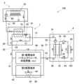
実施例に係る空調装置2について図面を参照して説明する。図1に示すように、空調装置2は、熱源機100と、第1暖房端末96(例えば、パネルラジエータ、床暖房機等)と、第2暖房端末90(例えば、ファンコンベクタ等)とを備えている。空調装置2は、熱源機100で加熱した暖房用熱媒を第2暖房端末90(或いは、第1暖房端末96)に供給し、第2暖房端末90(或いは、第1暖房端末96)において暖房用熱媒の熱を放熱することにより、室内(例えば、居室内)を暖房する装置である。
An
(熱源機100の構成)
熱源機100は、暖房用の水(暖房用熱媒)を加熱して温水を生成し、生成した温水を第1暖房端末96及び第2暖房端末90に供給する機器である。熱源機100は、例えば、電気式、ガス式、または、電気及びガス式の熱源機である。以下では、電気及びガス式の熱源機100の構成について説明する。
(Configuration of heat source unit 100)
The
熱源機100は、操作部102と、通信I/F104と、制御部106と、加熱部108とを備えている。操作部102は、複数のボタン(図示省略)を備えている。空調装置2のユーザや設置業者は、操作部102を操作することによって、様々な指示を熱源機100に入力することができる。
The
通信I/F104は、第2暖房端末90と有線通信または無線通信を実行するためのインターフェースである。通信I/F104は、第1暖房端末96と有線通信または無線通信を実行するためのインターフェースであってもよい。
The communication I/
制御部106は、揮発性メモリ、不揮発性メモリなどによって構成される記憶部107を備えており、記憶部107に記憶されているプログラムに従って、熱源機100の各部の動作を制御する。制御部106が実行する制御や処理については後述する。
The
(加熱部108の構成;図2)
次に、加熱部108の構成について説明する。図2に示すように、加熱部108は、熱交換ユニット7と、ヒートポンプ熱源4と、燃焼熱源3とを備えている。熱交換ユニット7は、熱交換器70を備えている。熱交換器70は、例えばプレート式の熱交換器であり、加熱用熱媒と暖房用熱媒との熱交換により、プレートを通過する水(暖房用熱媒)を加熱することができる。熱交換器70には、暖房往路52の上流端と、熱媒往路62の上流端が接続されている。熱交換器70で加熱された水(暖房用熱媒)が暖房往路52へ送り出される。熱交換器70で熱交換された加熱用熱媒が熱媒往路62へ送り出される。
(Configuration of
Next, the configuration of the
暖房往路52には、暖房出湯サーミスタ46が設けられている。暖房出湯サーミスタ46は、暖房往路52を流れる水の温度を検出する。暖房往路52の下流端には、第1暖房経路41の上流端と、第2暖房経路42の上流端と、凍結防止用バイパス路56の上流端が接続されている。
The
第1暖房経路41は、加熱部108から第1暖房端末96に温水(暖房用熱媒)を供給する経路である。第1暖房経路41は、加熱部108から第1暖房端末96を経由して再び加熱部108に戻るように構成されている。温水の熱が第1暖房端末96から放熱されることにより室内が暖房される。第1暖房端末96は、例えば、居室を暖房するためのパネルラジエータや床暖房機等である。
The
第2暖房経路42は、加熱部108から第2暖房端末90に温水(暖房用熱媒)を供給する経路である。第2暖房経路42は、加熱部108から第2暖房端末90を経由して再び加熱部108に戻るように構成されている。温水の熱が第2暖房端末90から放熱されることにより室内が暖房される。第2暖房端末90は、例えば、居室を暖房するためのファンコンベクタ等である。
The
第2暖房端末90は、暖房放熱器92と、暖房ファン94とを備えている。暖房放熱器92は、第2暖房経路42に設けられている。暖房用熱媒の熱が暖房放熱器92から放熱されることにより室内が暖房される。暖房ファン94は、暖房放熱器92に送風することにより、暖房放熱器92から放熱される熱を室内に供給する。
The
第1暖房経路41の下流端と、第2暖房経路42の下流端と、凍結防止用バイパス路56の下流端は、ヒートポンプ往路53の上流端に接続されている。ヒートポンプ往路53には、ヒートポンプ入水サーミスタ82が設けられている。ヒートポンプ入水サーミスタ82は、ヒートポンプ往路53を流れる水(暖房用熱媒)の温度を検出することにより、第2暖房端末90(或いは、第1暖房端末96)から熱源機100に戻された暖房用熱媒の温度を検出する。ヒートポンプ入水サーミスタ82の検出温度Pの情報は、熱源機100の制御部106(図1参照)に供給される。
The downstream end of the
ヒートポンプ熱源4は、ヒートポンプ往路53の下流端から流入する水を加熱して、ヒートポンプ復路51の上流端に送り出す。ヒートポンプ熱源4は、冷媒(例えばR32といったHFC冷媒や、R744といったCO2冷媒)を循環させるための冷媒循環路18と、圧縮機20と、凝縮器22と、減圧機構24と、蒸発器26と、ファン28を備えている。圧縮機20は、気相状態の冷媒を加圧して凝縮器22へ送り出す。凝縮器22は、水(暖房用熱媒)への放熱によって冷媒を凝縮させて、液相状態の冷媒を減圧機構24へ送り出す。減圧機構24は、例えば開度を調整可能な膨張弁であって、冷媒を減圧して蒸発器26へ送り出す。蒸発器26は、ファン28によって送風される外気からの吸熱によって冷媒を蒸発させて、気相状態の冷媒を圧縮機20へ送り出す。ヒートポンプ熱源4においては、ヒートポンプ往路53から送られた水(暖房用熱媒)が凝縮器22で加熱されて、加熱後の温水が凝縮器22からヒートポンプ復路51へ送り出される。
The heat
ヒートポンプ復路51には、第1循環ポンプ50と、ヒートポンプ出湯サーミスタ81が設けられている。第1循環ポンプ50が駆動すると、加熱部108と暖房放熱器96、90との間で水(暖房用熱媒)が循環する。ヒートポンプ出湯サーミスタ81は、ヒートポンプ復路51を流れる水の温度を検出する。
The heat
ヒートポンプ復路51の下流端には、三方弁55が設けられている。三方弁55には、暖房復路57の上流端と、加熱バイパス路54の上流端が接続されている。三方弁55は、ヒートポンプ復路51から暖房復路57に流れる水の流量と、ヒートポンプ復路51から加熱バイパス路54に流れる水の流量の割合を調整可能である。暖房復路57の下流端は、熱交換器70に接続されている。加熱バイパス路54の下流端は、暖房往路52に接続されている。
A three-
燃焼熱源3は、バーナ31と、熱交換器32を備えている。バーナ31は、都市ガス等の燃料を燃焼させる。熱交換器32には、熱媒往路62の下流端と、熱媒復路61の上流端が接続されている。熱交換器32は、熱媒往路62の下流端から流入する加熱用熱媒をバーナ31の燃焼熱によって加熱して、加熱後の加熱用熱媒を熱媒復路61の上流端へ送り出す。熱媒復路61の下流端は、熱交換器70に接続されている。
The
熱媒往路62には、熱動弁71と、第2循環ポンプ60が設けられている。熱動弁71は、熱媒往路62を開閉する。第2循環ポンプ60が駆動すると、熱交換器70と燃焼熱源3との間で加熱用熱媒が循環する。
The heat transfer
(第2暖房端末90の構成)
第2暖房端末90の構成について説明する。図1に示すように、第2暖房端末90は、操作部202と、表示部203と、通信I/F204と、制御部205とを備えている。なお、第2暖房端末90の暖房放熱器92と、暖房ファン94については、上述したので説明を省略する。
(Configuration of second heating terminal 90)
The configuration of the
操作部202は、複数のボタン(図示省略)を備えている。空調装置2のユーザは、操作部202を操作することによって、様々な指示を第2暖房端末90に入力することができる。例えば、ユーザは、操作部202を操作することによって、第2暖房端末90の暖房設定温度C(例えば、25℃)を入力することができる。また、ユーザは、操作部202を操作することによって、第2暖房端末90の暖房設定風量(例えば、中)を入力することができる。第2暖房端末90に入力される暖房設定温度や暖房設定風量の情報は、通信I/F204を介して熱源機100に送信される。熱源機100の制御部106は、第2暖房端末90から受信する暖房設定温度や暖房設定風量の情報を記憶部107に記憶する。
The
表示部203は、様々な情報を表示するためのディスプレイである。表示部203はタッチパネル(即ち操作部)として機能してもよい。表示部203は、例えば、第2暖房端末90の暖房設定温度や暖房設定風量を表示する。通信I/F204は、熱源機100と有線通信または無線通信を実行するためのインターフェースである。
The
制御部205は、揮発性メモリ、不揮発性メモリなどによって構成される記憶部206を備えており、記憶部206に記憶されているプログラムに従って、第2暖房端末90の各部の動作を制御する。例えば、制御部205は、第2暖房端末90の暖房設定風量(例えば、中)が設定されると、暖房ファン94の風量が暖房設定風量と一致するように暖房ファン94の動作を制御する。また、制御部205は、暖房ファン94の回転数が一定になるように暖房ファン94の動作を制御する。例えば、制御部205は、「中」の風量を維持するように暖房ファン94の回転数を維持する。
The
(熱媒温度制御処理)
次に、熱源機100の制御部106が実行する熱媒温度制御処理について説明する。図3は、実施例に係る熱媒温度制御処理のフローチャートである。熱媒温度制御処理は、例えば、空調装置2の電源がオンになると開始される。図3に示すように、熱媒温度制御処理のS2では、制御部106が、第2暖房端末90の現在の暖房設定温度Cを認識する。現在の暖房設定温度Cは、記憶部107に記憶されている。
(Heat medium temperature control process)
Next, the heat medium temperature control process executed by the
続くS4では、制御部106が、S2で認識した暖房設定温度Cに基づいて熱媒基準温度Tを算出する。制御部106は、下記の式(1)に基づいて熱媒基準温度Tを算出する。
T=B×(X-C)+C・・・式(1)
In the next S4, the
T=B×(X-C)+C...Formula (1)
式(1)において、Bは、所定の係数であり、例えば0.67である。また、Cは、第2暖房端末90の暖房設定温度であり、例えば25℃である。Xは、熱源機100から第2暖房端末90に供給する暖房用熱媒の熱媒設定温度である。Xの初期値は、第2暖房端末90の暖房設定温度Cに応じて設定される。その後、Xは、ヒートポンプ入水サーミスタ82の検出温度P(即ち、第2暖房端末90から熱源機100に戻された暖房用熱媒の温度)に応じて修正される(後述するS8、S10参照)。
In formula (1), B is a predetermined coefficient, for example 0.67. C is the heating setting temperature of the
続くS6では、制御部106が、ヒートポンプ入水サーミスタ82の検出温度PがS4で算出した熱媒基準温度Tよりも低いか否かを判断する。ヒートポンプ入水サーミスタ82の検出温度Pが熱媒基準温度Tよりも低い場合(P<Tの場合)は、処理はS8に進む(S6でYES)。検出温度Pが熱媒基準温度Tよりも低くない場合(NOの場合)は、処理はS10に進む。
In the next step S6, the
続くS8では、制御部106が、X(熱源機100から第2暖房端末90に供給する暖房用熱媒の熱媒設定温度)をY1℃高くする。修正後のXは、修正前のX+Y1℃である。制御部106は、熱源機100から第2暖房端末90に供給する暖房用熱媒の温度が修正後のXと一致するように、熱源機100の動作を制御する。例えば、制御部106は、加熱部108の三方弁55の開度、ヒートポンプ熱源4、燃焼熱源3のバーナ31の動作を制御する(図2参照)。
In the next step S8, the
上記のS6でNOの後のS10では、制御部106が、ヒートポンプ入水サーミスタ82の検出温度PがS4で算出した熱媒基準温度Tよりも高いか否かを判断する。ヒートポンプ入水サーミスタ82の検出温度Pが熱媒基準温度Tよりも高い場合(P>Tの場合)は、処理はS12に進む(S10でYES)。検出温度Pが熱媒基準温度Tよりも高くない場合(NOの場合)は、処理はS14に進む。S10でNOの場合は、P=Tである。
In S10 after NO in S6 above, the
続くS12では、制御部106が、X(熱源機100から第2暖房端末90に供給する暖房用熱媒の熱媒設定温度)をY2℃低くする。修正後のXは、修正前のX-Y2℃である。制御部106は、熱源機100から第2暖房端末90に供給する暖房用熱媒の温度が修正後のXと一致するように、熱源機100の動作を制御する。例えば、制御部106は、加熱部108の三方弁55の開度、ヒートポンプ熱源4、燃焼熱源3のバーナ31の動作を制御する(図2参照)。
In the next step S12, the
上記のS10でNOの後のS14では、制御部106が、X(熱源機100から第2暖房端末90に供給する暖房用熱媒の熱媒設定温度)を修正せずに維持する。
In S14 after NO in S10 above, the
続くS16では、制御部106が、S8、S12またはS14の処理から所定の時間(例えば、5分)が経過したか否かを判断する。所定の時間が経過した(YESの場合)場合は、処理はS2に戻る。所定の時間が経過しない(NOの場合)場合は、処理は待機する。制御部106は、S2からS14の処理を繰り返すことにより、所定の時間間隔(例えば、5分間隔)でXを修正または維持する。制御部106が熱媒温度制御処理を実行している間、第2暖房端末90の制御部205は、暖房ファン94の回転数が一定になるように暖房ファン94の動作を制御している。熱媒温度制御処理は、例えば、空調装置2の電源がオフになると終了する。
In the next step S16, the
以上、実施例について説明した。以上の説明から明らかなように、空調装置2は、暖房用熱媒の熱により室内を空調する第2暖房端末90と、第2暖房端末90に供給する暖房用熱媒を加熱する熱源機100とを備えている。空調装置2は、熱源機100で加熱された暖房用熱媒を第2暖房端末90に供給し、第2暖房端末90で放熱された暖房用熱媒を熱源機100に戻す構成である。また、空調装置2は、熱源機100に戻る暖房用熱媒の温度を検出するヒートポンプ入水サーミスタ82と、制御部106とを備えている。第2暖房端末90は、熱源機100から第2暖房端末90に供給された暖房用熱媒の熱を放熱する暖房放熱器92と、暖房放熱器92に送風して暖房放熱器92から放熱される暖房用熱媒の熱を室内に供給する暖房ファン94とを備えている。制御部106は、暖房ファン94の回転数が一定になるように暖房ファン94の動作が制御されている状態で、ヒートポンプ入水サーミスタ82の検出温度Pが第2暖房端末90の暖房設定温度Cに基づいて算出される熱媒基準温度Tと一致するように、熱源機100での暖房用熱媒の加熱量を制御して第2暖房端末90に供給する暖房用熱媒の温度を制御する(図3参照)。
The above describes the embodiment. As is clear from the above description, the
この構成によれば、暖房ファン94の回転数が大きく変動することを抑制することができる。また、第2暖房端末90に供給する暖房用熱媒の温度を制御することにより、適切な熱量で室内を空調することができる。例えば、第2暖房端末90から熱源機100に戻る暖房用熱媒の温度(即ち、ヒートポンプ入水サーミスタ82の検出温度P)が熱媒基準温度Tよりも低い場合は、室内を空調するための熱量が不足しており、今よりも大きい熱量が必要であると考えられる。そのため、この場合は、ヒートポンプ入水サーミスタ82の検出温度Pが熱媒基準温度Tと一致するように、熱源機100での暖房用熱媒の加熱量を大きくする。これにより、適切な熱量で室内を空調することができる。一方、第2暖房端末90から熱源機100に戻る暖房用熱媒の温度(即ち、ヒートポンプ入水サーミスタ82の検出温度P)が熱媒基準温度Tよりも大きい場合は、室内を空調するための熱量が余分であり、今よりも小さい熱量で足りると考えられる。そのため、この場合は、ヒートポンプ入水サーミスタ82の検出温度Pが熱媒基準温度Tと一致するように、熱源機100での暖房用熱媒の加熱量を小さくする。これにより、適切な熱量で室内を空調することができる。したがって、上記の構成によれば、暖房ファン94の回転数が大きく変動することを抑制することができると共に、適切な熱量で室内を暖房することができる。
According to this configuration, it is possible to suppress large fluctuations in the number of revolutions of the
また、上記の構成によれば、暖房ファン94の回転数が過大になることを抑制することができるので、暖房ファン94の騒音を抑制することができる。また、暖房ファン94の風量が過大になることを抑制することができる。更に、暖房用熱媒の温度が過剰に高くなることを抑制することができ、無駄なエネルギー消費を抑制することができる。
In addition, with the above configuration, the rotation speed of the
また、空調装置2では、熱媒基準温度Tが式(1)に基づいて算出される。この構成によれば、簡潔な計算により熱媒基準温度Tを迅速に算出することができる。そのため、熱源機100での暖房用熱媒の加熱量を迅速に制御することができる。
In addition, in the
(対応関係)
第2暖房端末90が「空調端末」の一例である。ヒートポンプ入水サーミスタ82が「温度センサ」の一例である。
(Correspondence)
The
以上、各実施例について詳細に説明したが、これらは例示に過ぎず、特許請求の範囲を限定するものではない。特許請求の範囲に記載の技術には、以上に例示した具体例を様々に変形、変更したものが含まれる。本明細書または図面に説明した技術要素は、単独であるいは各種の組合せによって技術的有用性を発揮するものであり、出願時請求項記載の組合せに限定されるものではない。また、本明細書または図面に例示した技術は複数目的を同時に達成し得るものであり、そのうちの一つの目的を達成すること自体で技術的有用性を持つものである。 Although each embodiment has been described in detail above, these are merely examples and do not limit the scope of the claims. The technology described in the claims includes various modifications and variations of the specific examples exemplified above. The technical elements described in this specification or drawings exert technical utility alone or in various combinations, and are not limited to the combinations described in the claims at the time of filing. Furthermore, the technology exemplified in this specification or drawings can achieve multiple objectives simultaneously, and achieving one of those objectives is itself technically useful.
2:空調装置、3:燃焼熱源、4:ヒートポンプ熱源、7:熱交換ユニット、41:第1暖房経路、42:第2暖房経路、46:暖房出湯サーミスタ、50:第1循環ポンプ、51:ヒートポンプ復路、52:暖房往路、53:ヒートポンプ往路、54:加熱バイパス路、55:三方弁、57:暖房復路、60:第2循環ポンプ、70:熱交換器、71:熱動弁、81:ヒートポンプ出湯サーミスタ、82:ヒートポンプ入水サーミスタ90:第2暖房端末、92:暖房放熱器、94:暖房ファン、96:第1暖房端末、100:熱源機、106:制御部、108:加熱部、205:制御部
Reference Signs List 2: air conditioner, 3: combustion heat source, 4: heat pump heat source, 7: heat exchange unit, 41: first heating path, 42: second heating path, 46: heating outlet hot water thermistor, 50: first circulation pump, 51: heat pump return path, 52: heating outward path, 53: heat pump outward path, 54: heating bypass path, 55: three-way valve, 57: heating return path, 60: second circulation pump, 70: heat exchanger, 71: thermal valve, 81: heat pump outlet hot water thermistor, 82: heat pump inlet water thermistor 90: second heating terminal, 92: heating radiator, 94: heating fan, 96: first heating terminal, 100: heat source unit, 106: control unit, 108: heating unit, 205: control unit
Claims (2)
前記空調端末に供給する熱媒を加熱する熱源機と、を備えており、
前記熱源機で加熱された熱媒を前記空調端末に供給し、前記空調端末で放熱された熱媒を前記熱源機に戻す空調装置であって、
前記熱源機に戻る熱媒の温度を検出する温度センサと、
制御部と、を備えており、
前記空調端末は、前記熱源機から前記空調端末に供給された熱媒の熱を放熱する放熱機と、前記放熱機に送風して前記放熱機から放熱される熱媒の熱を室内に供給するファンと、を備えており、
前記制御部は、前記ファンの回転数が一定になるように前記ファンの動作が制御されている状態で、前記温度センサにより検出される熱媒の温度が前記空調端末の空調設定温度に基づいて算出される熱媒基準温度と一致するように、前記熱源機での熱媒の加熱量を制御して前記空調端末に供給する熱媒の温度を制御する、空調装置。 an air conditioning terminal that air-conditions the room by using heat from a heat medium;
A heat source device that heats a heat medium to be supplied to the air conditioning terminal,
An air conditioning device that supplies a heat medium heated by the heat source device to the air conditioning terminal and returns a heat medium dissipated by the air conditioning terminal to the heat source device,
A temperature sensor for detecting the temperature of the heat medium returning to the heat source device;
A control unit,
The air-conditioning terminal includes a radiator that radiates heat of a heat medium supplied from the heat source device to the air-conditioning terminal, and a fan that blows air to the radiator and supplies the heat of the heat medium radiated from the radiator to a room,
The control unit controls the amount of heating of the heat medium in the heat source unit to control the temperature of the heat medium supplied to the air conditioning terminal so that the temperature of the heat medium detected by the temperature sensor matches a heat medium reference temperature calculated based on the air conditioning set temperature of the air conditioning terminal, while controlling the operation of the fan so that the rotation speed of the fan is constant.
T=B×(X-C)+C・・・式(1)
式(1)において、Tは、前記熱媒基準温度であり、Bは、所定の係数であり、Xは、前記熱源機から前記空調端末に供給する熱媒の熱媒設定温度であり、Cは、前記空調端末の空調設定温度である。
The air conditioner according to claim 1 , wherein the heat medium reference temperature is calculated based on the following formula (1):
T=B×(X-C)+C...Formula (1)
In formula (1), T is the heat medium reference temperature, B is a predetermined coefficient, X is the heat medium setting temperature of the heat medium supplied from the heat source unit to the air conditioning terminal, and C is the air conditioning setting temperature of the air conditioning terminal.
Priority Applications (1)
| Application Number | Priority Date | Filing Date | Title |
|---|---|---|---|
| JP2021063108A JP7569737B2 (en) | 2021-04-01 | 2021-04-01 | Air conditioning equipment |
Applications Claiming Priority (1)
| Application Number | Priority Date | Filing Date | Title |
|---|---|---|---|
| JP2021063108A JP7569737B2 (en) | 2021-04-01 | 2021-04-01 | Air conditioning equipment |
Publications (2)
| Publication Number | Publication Date |
|---|---|
| JP2022158320A JP2022158320A (en) | 2022-10-17 |
| JP7569737B2 true JP7569737B2 (en) | 2024-10-18 |
Family
ID=83639054
Family Applications (1)
| Application Number | Title | Priority Date | Filing Date |
|---|---|---|---|
| JP2021063108A Active JP7569737B2 (en) | 2021-04-01 | 2021-04-01 | Air conditioning equipment |
Country Status (1)
| Country | Link |
|---|---|
| JP (1) | JP7569737B2 (en) |
-
2021
- 2021-04-01 JP JP2021063108A patent/JP7569737B2/en active Active
Also Published As
| Publication number | Publication date |
|---|---|
| JP2022158320A (en) | 2022-10-17 |
Similar Documents
| Publication | Publication Date | Title |
|---|---|---|
| JP5452581B2 (en) | HEAT PUMP SYSTEM AND HEAT PUMP DEVICE CONTROL METHOD | |
| JPH0518630A (en) | Air conditioner | |
| JP5869648B1 (en) | Air conditioning system | |
| JP2801675B2 (en) | Air conditioner | |
| CN108688434A (en) | Air conditioner for vehicles | |
| KR20180130471A (en) | Heating device and hot water supplying device | |
| US20210033324A1 (en) | Heat pump system | |
| JP7569737B2 (en) | Air conditioning equipment | |
| JP3206245B2 (en) | Air conditioner | |
| JP6907653B2 (en) | Air conditioning system | |
| JP2005156030A (en) | Heat pump apparatus | |
| JP7523397B2 (en) | Air Conditioning System | |
| US20100043465A1 (en) | Heat pump system and method of controlling the same | |
| JP7019215B1 (en) | Simultaneous cold and hot temperature control device | |
| JP2014005961A (en) | Refrigeration cycle device and hot water generator including the same | |
| JP2576354B2 (en) | Air flow control method for air conditioner | |
| JP7019213B1 (en) | Simultaneous cold and hot temperature control device | |
| JP3979909B2 (en) | Hot water storage water heater | |
| JP3901624B2 (en) | Heating operation method of air conditioning system | |
| JP2002295899A (en) | Hot water supply heat source device | |
| JP7019212B1 (en) | Simultaneous cold and hot temperature control device | |
| JP6978118B1 (en) | Simultaneous cold and hot temperature control device | |
| JP7019211B1 (en) | Simultaneous cold and hot temperature control device | |
| JP7731322B2 (en) | Air conditioning system | |
| JP7523380B2 (en) | Hybrid hot water heating system |
Legal Events
| Date | Code | Title | Description |
|---|---|---|---|
| A621 | Written request for application examination |
Free format text: JAPANESE INTERMEDIATE CODE: A621 Effective date: 20231122 |
|
| A977 | Report on retrieval |
Free format text: JAPANESE INTERMEDIATE CODE: A971007 Effective date: 20240619 |
|
| A131 | Notification of reasons for refusal |
Free format text: JAPANESE INTERMEDIATE CODE: A131 Effective date: 20240702 |
|
| TRDD | Decision of grant or rejection written | ||
| A01 | Written decision to grant a patent or to grant a registration (utility model) |
Free format text: JAPANESE INTERMEDIATE CODE: A01 Effective date: 20240924 |
|
| A61 | First payment of annual fees (during grant procedure) |
Free format text: JAPANESE INTERMEDIATE CODE: A61 Effective date: 20241007 |
|
| R150 | Certificate of patent or registration of utility model |
Ref document number: 7569737 Country of ref document: JP Free format text: JAPANESE INTERMEDIATE CODE: R150 |