JP7567006B2 - Image forming device - Google Patents
Image forming device Download PDFInfo
- Publication number
- JP7567006B2 JP7567006B2 JP2023160177A JP2023160177A JP7567006B2 JP 7567006 B2 JP7567006 B2 JP 7567006B2 JP 2023160177 A JP2023160177 A JP 2023160177A JP 2023160177 A JP2023160177 A JP 2023160177A JP 7567006 B2 JP7567006 B2 JP 7567006B2
- Authority
- JP
- Japan
- Prior art keywords
- door
- image forming
- forming apparatus
- locking member
- housing
- Prior art date
- Legal status (The legal status is an assumption and is not a legal conclusion. Google has not performed a legal analysis and makes no representation as to the accuracy of the status listed.)
- Active
Links
Images


Landscapes
- Electrophotography Configuration And Component (AREA)
- Accessory Devices And Overall Control Thereof (AREA)
Description
本発明は、同一方向に開閉するドアを開閉する際に用いられるロック機構を有するプリンタ、複写機などの画像形成装置に関する。 The present invention relates to an image forming device such as a printer or copier that has a locking mechanism used when opening and closing doors that open and close in the same direction.
従来、電子写真方式を利用したプリンタや複写機などの画像形成装置の中には画像形成装置本体の一側面に複数の扉をもつものがある(例えば、特許文献1参照)。特許文献1の画像形成装置にて、一つの扉は装置本体のカートリッジドアであり、他の一つの扉は給送トレイドアとされている。そして、カートリッジドアを開けた際に給送トレイドアが開閉可能である。 Conventionally, some image forming devices, such as printers and copiers, that use electrophotography have multiple doors on one side of the main body of the image forming device (see, for example, Patent Document 1). In the image forming device of Patent Document 1, one door is a cartridge door for the main body of the device, and the other door is a feed tray door. When the cartridge door is opened, the feed tray door can be opened and closed.
しかしながら、カートリッジドアを開けた際に給送トレイドアを開閉可能とすると、カートリッジドアを開く過程で給送トレイドアが開いてしまうおそれがあり、ユーザが混乱するおそれがある。また、カートリッジドアのみを開けるつもりが、その外にある給送トレイドアも開いてしまうと、閉める際、カートリッジドアを閉めるのに加えて、給送トレイドアをもう一度閉める手間が発生する。 However, if the feed tray door can be opened and closed when the cartridge door is opened, there is a risk that the feed tray door may open in the process of opening the cartridge door, which may confuse the user. Also, if the intention is to open only the cartridge door but the outer feed tray door also opens, the user will have to go through the trouble of closing the cartridge door as well as the feed tray door again when closing the door.
本発明の目的は、カートリッジドアが開いた際に給送トレイドアが開くのを自動的に規制するロック機構を設けることで、ユーザビリティを向上させることである。 The object of the present invention is to improve usability by providing a locking mechanism that automatically prevents the feed tray door from opening when the cartridge door is opened.
上記目的を達成するための本発明の代表的な構成は、開口を有する筐体と、前記開口を通じて前記筐体の内部と外部の間を移動可能な移動ユニットと、前記筐体に対して移動可能であり、前記開口を覆う閉じ位置と、前記開口を露出する開き位置と、に移動可能な第1ドアであって、前記筐体と当接可能な当接部材と、前記当接部材の移動に連動して係止位置と解除位置とに移動可能に構成された係止部材と、を有する第1ドアと、被係止部を備える第2ドアと、を有し、前記係止部材が前記係止位置に位置され、前記被係止部に係合した状態では、前記第2ドアは前記第1ドアと一体的に移動するように、前記第1ドアに対する前記第2ドアの移動が規制され、前記係止部材が前記解除位置に位置され、前記被係止部から離れた状態では、前記第2ドアは前記第1ドアに対して開閉可能であり、前記第1ドアが前記閉じ位置に位置するとき、前記当接部材は前記筐体と当接した状態をとり、前記係止部材は前記解除位置に位置し、かつ前記当接部材と前記係止部材は鉛直方向で所定の位置に位置し、前記第1ドアが前記閉じ位置から前記開き位置へ向けて移動することにより、前記当接部材が前記筐体から離れ、前記係止部材は前記解除位置から前記係止位置に移動し、前記筐体の内部と外部の間を移動するとき、前記移動ユニットは前記所定の位置よりも低い位置を通ることを特徴とする。 A representative configuration of the present invention for achieving the above object includes a housing having an opening, a moving unit capable of moving between the inside and outside of the housing through the opening, a first door that is movable relative to the housing and can be moved between a closed position that covers the opening and an open position that exposes the opening, the first door having an abutting member that can abut against the housing and a locking member configured to be movable between an engaged position and a released position in conjunction with the movement of the abutting member, and a second door having an engaged portion, and a movement control unit that controls the movement of the second door relative to the first door so that when the locking member is positioned at the engaged position and engaged with the engaged portion, the second door moves integrally with the first door. When the movement of the second door is restricted, the locking member is positioned at the release position and is separated from the locked portion, the second door can be opened and closed relative to the first door, and when the first door is positioned at the closed position, the abutting member is in abutment with the housing, the locking member is positioned at the release position, and the abutting member and the locking member are positioned at a predetermined position in the vertical direction, and when the first door moves from the closed position to the open position, the abutting member moves away from the housing and the locking member moves from the release position to the locking position, and when moving between the inside and outside of the housing, the moving unit passes through a position lower than the predetermined position.
上記構成により、カートリッジドアのユーザビリティを向上させることができる。 The above configuration improves the usability of the cartridge door.
〔第1実施形態〕
第1実施形態に係るロック機構を説明する。図1は第1実施形態の画像形成装置の概略構成を示す断面図である。
First Embodiment
A lock mechanism according to the first embodiment will now be described with reference to Fig. 1, which is a cross-sectional view showing a schematic configuration of an image forming apparatus according to the first embodiment.
図1に示すように、画像形成装置10は、4つのプロセスカートリッジ11(画像形成部)を有する。図1に示すプロセスカートリッジ11(11Y、11M、11C、11K)には、それぞれ、イエロー(Y)、マゼンタ(M)、シアン(C)、ブラック(K)の色のトナーが、現像器内に収納され、対応する色のトナー像を形成する。各プロセスカートリッジ11(11Y、11M、11C、11K)の内部構成は同様であるため、以下の説明では、必要な場合を除き、添え字であるY、M、C、Kを省略する。
As shown in FIG. 1, the
(画像形成装置)
画像形成装置10は、上述のように、4つのプロセスカートリッジ11を備わる。プロセスカートリッジ11には、感光体ドラム1(像担持体)と、感光体ドラム1に作用するプロセス手段を有する。プロセス手段としては、例えば、帯電ローラ2、現像ローラ4、一次転写部材6、クリーニング部材7等がある。4つのプロセスカートリッジ11の上部には、レーザー光を照射する露光部3が配置される。
(Image forming apparatus)
As described above, the
感光体ドラム1は、ドラム状の電子写真感光体である。帯電ローラ2は、感光体ドラム1を所定の極性・電位に一様に帯電する。露光部3は、感光体ドラム1上にレーザー光を照射し、感光体ドラム1上に静電潜像を形成する。現像ローラ4は、トナーが収納される現像器内に配設され、前記静電潜像にトナーを供給することで、感光体ドラム1上にトナー像を形成する。一次転写部材6は、中間転写ベルト5を介して、感光体ドラム1に対向配置され、前記トナー像を後述の中間転写ベルト5に転写(一次転写)する。クリーニング部材7は、一次転写において転写されずに感光体ドラム1上に残った残トナーを感光体ドラム1から除去する。
The photoconductor drum 1 is a drum-shaped electrophotographic photoconductor. The
中間転写ベルト5は無端状のベルトである。中間転写ベルト5は、複数の張架部材により懸架され、4つのプロセスカートリッジ11における、感光体ドラム1と一次転写部材6との間(一次転写部)に搬送される。
The
上記構造により、プロセスカートリッジ11における画像形成の際には、まず、感光体ドラム1は、帯電ローラ2により所定の極性・電位に一様に帯電処理される。次いで、感光体ドラム1が露光部3により像露光を受けることにより、目的のカラー画像の色成分像に対応した静電潜像が形成される。
When forming an image in the process cartridge 11, the above structure first uniformly charges the photosensitive drum 1 to a predetermined polarity and potential by the
そして、感光体ドラム1上の静電潜像には、感光体ドラム1と現像ローラ4との間の現像位置において、現像ローラ4によってトナーが供給される。これにより前記静電潜像が現像され、トナー像として可視化される。 Then, toner is supplied to the electrostatic latent image on the photosensitive drum 1 by the developing roller 4 at the development position between the photosensitive drum 1 and the developing roller 4. This develops the electrostatic latent image and makes it visible as a toner image.
各感光体ドラム1上に形成されたトナー像は、各感光体ドラム1と中間転写ベルト5との当接部を通過する過程で中間転写ベルト5の上に一次転写される。そして、4色のトナー像が中間転写ベルト5上に順次重ねて転写されると、目的のカラー画像に対応した合成カラー画像が中間転写ベルト5上に得られる。
The toner images formed on each photosensitive drum 1 are primarily transferred onto the
次に、二次転写と、転写材Sの給送から排出までの構造及び動作を説明する。 Next, we will explain the secondary transfer and the structure and operation from feeding to discharging the transfer material S.
中間転写ベルト5の一部に対向する部分には、二次転写ローラ12が配設される。中間転写ベルト5と二次転写ローラ12が対向するニップ部は二次転写部と呼ばれる。
A
次に、転写材Sの給送部の構成について説明する。 Next, the configuration of the transfer material S feeding section will be described.
中間転写ベルト5の下方には、転写材Sを収納する給送カセット8が配設される。給送カセット8に積載された転写材Sは、給送ローラ13a(給送部材)によって一枚ずつ分離され、二次転写部に向かって給送される。
A
また、画像形成装置10の側方には手差し仕様の給送トレイ9が配設され、転写材Sを収納可能である。給送トレイ9は、ヒンジ21を回動中心として回動する給送トレイドア30によって、装置本体に対して開閉可能である。このため、給送トレイ9を使用する際は、ユーザが給送トレイドア30を開放して、転写材Sを積載可能な状態にする(図1の状態)。給送トレイ9に積載された転写材Sは、給送ローラ13b(給送部材)によって一枚ずつ分離され、二次転写部に向かって給送される。
A
上記構成により、給送カセット8または給送トレイ9に収容される転写材Sが給送される。そして、転写材Sが二次転写部に差し掛かるタイミングで、中間転写ベルト5上のトナー像が転写材Sに対して二次転写される。
The above configuration feeds the transfer material S stored in the
その後、4色のトナー像を担持した転写材Sは、定着器14に導入される。定着器14内では、加熱および加圧がなされることで、4色のトナーが溶融混色し、且つ転写材Sに固定される。以上の動作により、フルカラーのプリント画像が転写材S上に形成される。最後に、転写材Sは画像形成装置10の外に排出される。
Then, the transfer material S carrying the four-color toner image is introduced into the
(開閉扉の概略構成)
次に、画像形成装置10の内部をメンテナンスする場合に開閉する開閉扉の構造について説明する。図2は第1実施形態のカートリッジドアを開放した場合の概略構成を示す断面図である。
(General configuration of the opening and closing door)
Next, there will be described the structure of the door that is opened and closed when performing maintenance on the inside of the
プロセスカートリッジ11を装置外に取り出して交換する場合など、プロセスカートリッジ11のメンテナンスを行う際には、まず、装置側面にあるカートリッジドア20(第一ドア)を、ヒンジ21を回動中心として回動させて、開放する。
When performing maintenance on the process cartridge 11, such as when removing the process cartridge 11 from the device for replacement, first open the cartridge door 20 (first door) on the side of the device by rotating it around the
カートリッジドア20は、画像形成装置10に対してヒンジ21を中心に回動し、外装16に対して開閉可能に取り付けられる。カートリッジドア20は、画像形成中には、装置本体の外装16に対して閉じられている(図1参照)。この状態では、カートリッジドア20に設けられた不図示の被係合部が画像形成装置10に設けられた不図示の係合部と係合している。
The
画像形成装置10の表面には、係合を解除するための不図示の解除ボタンが設けられている。カートリッジドア20を開く際に、ユーザはこの不図示の解除ボタンを押す。これにより、不図示のカートリッジドア20の被係合部と画像形成装置10の係合部との係合が解除され、カートリッジドア20が僅かに開く。
A release button (not shown) for releasing the engagement is provided on the surface of the
次に、ユーザは、ヒンジ21を中心としてカートリッジドア20を回動させる。これにより、ユーザは、図2に示すようにヒンジ21を中心に回転させてカートリッジドア20を画像形成装置10本体に対して開くことができる。
Next, the user rotates the
また、図2に示すように、4つのプロセスカートリッジ11は、カートリッジトレイ15に一体的に組み付けられている。このため、カートリッジドア20を開いた状態で、ユーザがカートリッジトレイ15を本体外側へ引き出すと、プロセスカートリッジ11の脱着を行うことができる。
As shown in FIG. 2, the four process cartridges 11 are integrally assembled to the
カートリッジドア20を画像形成装置10に対して閉じた状態にすると、カートリッジドア20の不図示の被係合部は、画像形成装置10の不図示の係合部と係合する。これにより、カートリッジドア20は、閉じられた状態で維持される。
When the
また、給送トレイドア30(第二ドア)は、ヒンジ21を中心に回動可能に取り付けられる。これにより、給送トレイドア30は、画像形成装置10およびカートリッジドア20と同一方向に回動する。給送トレイドア30から転写材Sを給送する場合、給送ローラ13bによって給送動作が行われる。
The feed tray door 30 (second door) is attached so as to be rotatable about the
図1及び図2に示すように、ロック機構40はカートリッジドア20の上端(ヒンジ21と反対側の端部)に備えられる。ロック機構40は、カートリッジドア20が閉じている際には、給送トレイドア30を自由に開閉できるように、カートリッジドア20を保持する(図1参照)。一方、カートリッジドア20が開いた状態においては、ロック機構40は、給送トレイドア30とカートリッジドア20とを一体的に動くように固定する(図2参照)。このように、ロック機構40はカートリッジドア20の開閉に連動してロック解除動作を行う。
As shown in Figures 1 and 2, the
(ロック機構の説明)
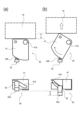
次に、ロック機構40について、図3乃至図6を用いて詳細に説明する。図3は第1実施形態のロック機構の全体構成を示す下方からみた斜視図である。図4は第1実施形態のロック機構の動作を示す上面図である。図5は第1実施形態のカートリッジドアが閉状態のロック機構の状態を示す斜視図である。
(Description of the locking mechanism)
Next, the
図3に示すように、ロック機構40は、回転カム41(回転部材)と、ストッパー42と、付勢部材43とから構成される。
As shown in FIG. 3, the
回転カム41には、その下面端部にカートリッジドア20の上端に形成される突起20a(図5参照)に嵌め込まれる軸孔41aが形成される。軸孔41aは回転カム41を回動させる回動軸として機能する。軸孔41aの対向する側面には、ストッパー42をガイドするガイド溝41bが形成される。
The rotating
ストッパー42は、回転カム41のガイド溝41bにガイドされるガイド軸42bと、ガイド軸42bによって軸孔41aと対向する側の回転カム41側方に位置し、その先端が回転カム41の下方に突出する先端部42aと、から構成される。ストッパー42のガイド軸42bが、回転カム41のガイド溝41bに入り込むことで、ストッパー42は回転カム41に互いに組み付くこととなる。
The
付勢部材43は、回転カム41に対して付勢力を与えるバネ部材であり、軸孔41aを軸として回転カム41に一定の方向に回動付勢する。
The biasing
図4に示すように、回転カム41の側面に形成されるガイド溝41bは、斜めに切り欠かれた状態である。一方、ストッパー42のガイド軸42bは、回転カム41の回動状態に関わらず、所定方向(カートリッジドア20から給送トレイドア30に向かう方向)に突出している。このため、回転カム41が回転すると、ストッパー42のガイド軸42bが、回転カム41のガイド溝41bに沿って、上下に動くことになる。これにより、ストッパー42は、図4(a)に示すロック解除位置と図4(b)に示すロック位置との間を移動する。
As shown in FIG. 4, the
ロック機構40と画像形成装置10の本体の各部との関係は、次の通りである。
The relationship between the locking
まず、図5に示すように、カートリッジドア20には、その天面から突出した突起20aが形成される。カートリッジドア20が閉まった状態において、ロック機構40のストッパー42は、下方に突出した先端部42aが、カートリッジドア20の天面に形成される開口22に対して係止されている。
First, as shown in FIG. 5, the
ここで、ロック機構40の動作と、画像形成装置10の外装16、カートリッジドア20、給送トレイドア30との係合関係を説明する。
Here, we will explain the operation of the
図6は第1実施形態のロック機構の動作を示す斜視図である。図6において、(a)はカートリッジドア20が閉じている状態を示す。すなわち、カートリッジドア20の天面が外装16に接触している状態を示す。一方、(b)はカートリッジドア20が開放された状態を示す。すなわち、カートリッジドア20の天面が外装16から離間している状態を示す。
Figure 6 is a perspective view showing the operation of the locking mechanism of the first embodiment. In Figure 6, (a) shows the
カートリッジドア20が閉じている際、図6(a)に示すように、回転カム41の軸孔41aに近い方の側面は、外装16に当接している。このため、ロック機構40の姿勢が決まっている。
When the
カートリッジドア20を開くと、図6(b)に示すように、回転カム41が外装16から離れるため、図中の矢印方向へ回動可能となる。そして、回転カム41は、付勢部材43の付勢力によって、回転中心となる軸孔41aを中心に回転する。
When the
すると、まず、図6(b)に示すように、ストッパー42の先端部42aがカートリッジドア20の開口22から外れる。次に、ストッパー42のガイド軸42bが回転カム41のガイド溝41bにガイドされる。これにより、ストッパー42は下降する(図4参照)。
First, as shown in FIG. 6(b), the
また、上述のように、ストッパー42は所定方向に突出しているので、回転カム41の回動に伴って、ストッパー42は回転カム41に押し出される。このとき、ストッパー42は、カートリッジドア20の天面の領域から外れ、図6(b)に示すように、給送トレイドア30側へ飛び出すこととなる。同時に、下降したストッパー42の先端部42aは、給送トレイドア30の上端面に形成されたトレイドア開口33に係合する。
As described above, the
一方、カートリッジドア20を閉める過程では、回転カム41が軸孔41aを中心として回動して元の状態に戻っていく。これに伴って、ストッパー42のガイド軸42bが、回転カム41のガイド溝41bに沿って上方に移動する。これにより、ストッパー42が上昇し、その過程でストッパー42の先端部42aは給送トレイドア30のトレイドア開口33から外れる。
Meanwhile, in the process of closing the
そして、カートリッジドア20を完全に閉めると、回転カム41の側面が外装16の端部とが接触した状態となる。この状態で、ストッパー42の先端部42aは開口22に係止される。
When the
このように、カートリッジドア20が閉まった状態では、ストッパー42の先端部42aはカートリッジドア20の内部にある開口22に係止されている。このため、給送トレイドア30はカートリッジドア20に対して固定されていない。すると、給送トレイドア30は自由に開閉することができる。
In this way, when the
一方、給送トレイドア30を閉めたままの状態で、カートリッジドア20を開けていくと、その過程でストッパー42の先端部42aが給送トレイドア30のトレイドア開口33に入り込む。すると、給送トレイドア30はカートリッジドア20に対して固定された状態となる。このため、カートリッジドア20は給送トレイドア30と一体となって開閉される。このように、カートリッジドア20を開放する過程で給送トレイドア30が開いてしまうことがない。
On the other hand, when the
そして、カートリッジドア20を画像形成装置10の本体に対して閉じると、給送トレイドア30もカートリッジドア20と一体的に移動して画像形成装置10の本体に対して閉じた状態となる。このように、カートリッジドア20の開閉動作に連動してロック機構40が動作する。これにより、給送トレイドア30の開閉を制御することができる。
When the
なお、給送トレイドア30を閉じた状態でカートリッジドア20を開ける場合には、カートリッジドア20の開放用のボタンを画像形成装置10の装置筐体に構成することが、操作性向上のため好ましい。
When opening the
また、ストッパー42の先端部42aは、給送トレイドア30側の部分が一部切り欠かれた斜面状である。これは、次の理由による。
The
すなわち、給送トレイドア30が既に開状態となっていて、その後、カートリッジドア20が開けられた時に、ロック機構40のストッパー42は既に給送トレイドア30側に突出した状態である。この状態において、カートリッジドア20が給送トレイドア30に当接する場合、まず、ロック機構40のストッパー42の先端部42aが給送トレイドア30に当接する。ここで、先端部42aが斜面状に形成されていると、給送トレイドア30の端部が斜面状の面を押し上げ、ストッパー42の先端部42aをトレイドア開口33まで円滑にガイドすることができる。
That is, when the
なお、ロック機構40のカートリッジドア20の端部上の位置は、図5及び図6においては明確に示しておらず、限定するものでもない。ただし、カートリッジドア20と給送トレイドア30とのロックをより効果的に行うためには、ロック機構40を、カートリッジドア20の幅方向の中央に設置することが好ましい。
The position of the
以上の構成は本実施形態の一例を示したものであり、本発明はこれに限定されるものではない。 The above configuration is an example of this embodiment, and the present invention is not limited to this.
〔第2実施形態〕
第2実施形態に係るロック機構を説明する。前述と同様の構成については、同符号を付し、説明を省略する。図7は第2実施形態のロック機構の動作を示す上面図である。
Second Embodiment
A lock mechanism according to a second embodiment will be described. The same components as those described above are given the same reference numerals and the description will be omitted. Fig. 7 is a top view showing the operation of the lock mechanism according to the second embodiment.
第1実施形態のロック機構40は、回動する回転カム41と上下動するストッパー42の2部材で構成され、回転カム41側にカム部(ガイド溝41b)がある構成について説明した。しかし、これに限定されるものではない。
The
図7に示すように、本実施形態のロック機構50は、回動する回転部材51と上下動するストッパー52の2部材で構成され、上下動するストッパー52側にカム部(ガイド溝52b)がある構成である。
As shown in FIG. 7, the
回転部材51は軸孔51aを中心として回動する部材で、軸孔51aに対向する側の側面にはガイド軸51bが形成される。一方、ストッパー52の側面には、ガイド軸51bをガイドするように斜めに切り欠かれたガイド溝52bが形成される。このため、回転部材51が回転すると、回転部材51のガイド軸51bが、ストッパー52のガイド溝52bに沿って、上下に動くことになる。このようにストッパー52が上下動する結果、ストッパー52の下端に下方に突出して形成される先端部52aも上下に移動する。
The rotating
ロック機構50は上記構成でカートリッジドア20に組み付けられることにより、カートリッジドア20が画像形成装置10に対して閉じた状態の時には、ストッパー52の先端部52aは上昇した状態である(図7(a)の状態)。
By assembling the
この状態では、先端部52aが給送トレイドア30に入り込んでいないので、給送トレイドア30は、カートリッジドア20に対して自由に当接又は離間をすることができる。よって、給送トレイドア30は、カートリッジドア20に対して自由に開閉することができる。
In this state, the
一方、回転部材51を回動させ、ストッパー52の先端部52aが下降した時(図7(b)の状態)に、先端部52aが給送トレイドア30に形成されたトレイドア開口33に入り込む。すると、カートリッジドア20に対して給送トレイドア30が一体的に固定される。
On the other hand, when the rotating
このように、ストッパー52は、図7(a)に示すロック解除位置と図7(b)に示すロック位置との間を移動する。
In this way, the
カートリッジドア20が開いた場合に給送トレイドア30をカートリッジドア20に対してロック可能に構成することで、カートリッジドア20を開いていく際に給送トレイドア30を持ってしまっても、問題なくカートリッジドア20を開くことができる。
By configuring the
また、ストッパー52の先端部52aは、給送トレイドア30側の部分が一部切り欠かれた斜面状である。このため、前述の実施形態と同一の理由により、ストッパー52の先端部52aをトレイドア開口33まで円滑にガイドすることができる。
The
10…画像形成装置
16…外装
20…カートリッジドア
21…ヒンジ
30…給送トレイドア
40…ロック機構
41a…軸孔
REFERENCE SIGNS LIST 10: image forming apparatus 16: exterior 20: cartridge door 21: hinge 30: feed tray door 40:
Claims (17)
前記開口を通じて前記筐体の内部と外部の間を移動可能な移動ユニットと、
前記筐体に対して移動可能であり、前記開口を覆う閉じ位置と、前記開口を露出する開き位置と、に移動可能な第1ドアであって、前記筐体と当接可能な当接部材と、前記当接部材の移動に連動して係止位置と解除位置とに移動可能に構成された係止部材と、を有する第1ドアと、
被係止部を備える第2ドアと、
を有し、
前記係止部材が前記係止位置に位置され、前記被係止部に係合した状態では、前記第2ドアは前記第1ドアと一体的に移動するように、前記第1ドアに対する前記第2ドアの移動が規制され、
前記係止部材が前記解除位置に位置され、前記被係止部から離れた状態では、前記第2ドアは前記第1ドアに対して開閉可能であり、
前記第1ドアが前記閉じ位置に位置するとき、前記当接部材は前記筐体と当接した状態をとり、前記係止部材は前記解除位置に位置し、かつ前記当接部材と前記係止部材は鉛直方向で所定の位置に位置し、
前記第1ドアが前記閉じ位置から前記開き位置へ向けて移動することにより、前記当接部材が前記筐体から離れ、前記係止部材は前記解除位置から前記係止位置に移動し、
前記筐体の内部と外部の間を移動するとき、前記移動ユニットは前記所定の位置よりも低い位置を通ることを特徴とする画像形成装置。 A housing having an opening;
a moving unit movable between the inside and the outside of the housing through the opening;
a first door that is movable relative to the housing and can be moved between a closed position that covers the opening and an open position that exposes the opening, the first door having an abutting member that can abut against the housing and a locking member that is configured to be movable between an engaging position and a releasing position in conjunction with the movement of the abutting member;
A second door having a latched portion;
having
When the locking member is positioned at the locking position and engaged with the locked portion, the movement of the second door relative to the first door is restricted so that the second door moves integrally with the first door,
When the locking member is located at the release position and is separated from the locked portion, the second door can be opened and closed relative to the first door,
when the first door is located at the closed position, the abutting member is in abutment with the housing, the locking member is located at the release position, and the abutting member and the locking member are located at predetermined positions in the vertical direction;
When the first door moves from the closed position toward the open position, the abutting member moves away from the housing and the locking member moves from the release position to the locking position,
The image forming apparatus according to claim 1, wherein the moving unit passes through a position lower than the predetermined position when moving between the inside and outside of the housing.
前記当接部材と前記係止部材の他方は前記突起が挿入される挿入部を有し、
前記挿入部と前記突起が互いに対して移動することにより、前記係止部材の移動と前記当接部材の移動が連動することを特徴とする請求項1乃至11のいずれか1項に記載の画像形成装置。 One of the abutting member and the locking member has a protrusion,
the other of the abutting member and the locking member has an insertion portion into which the protrusion is inserted,
12. The image forming apparatus according to claim 1, wherein the insertion portion and the protrusion move relative to each other, thereby interlocking the movement of the locking member with the movement of the abutting member.
前記第1ドアと前記第2ドアの間から供給された前記記録材を搬送する搬送部材を有することを特徴とする請求項1乃至16のいずれか1項に記載の画像形成装置。 a recording material can be supplied from between the first door and the second door into the housing when the first door is in the closed position and the second door is in an open state;
17. The image forming apparatus according to claim 1, further comprising a conveying member that conveys the recording material supplied from between the first door and the second door.
Priority Applications (1)
| Application Number | Priority Date | Filing Date | Title |
|---|---|---|---|
| JP2023160177A JP7567006B2 (en) | 2020-05-15 | 2023-09-25 | Image forming device |
Applications Claiming Priority (4)
| Application Number | Priority Date | Filing Date | Title |
|---|---|---|---|
| JP2020086232A JP6957681B2 (en) | 2019-04-10 | 2020-05-15 | Image forming device |
| JP2021164644A JP7124193B2 (en) | 2020-05-15 | 2021-10-06 | image forming device |
| JP2022122201A JP7358579B2 (en) | 2020-05-15 | 2022-07-29 | Image forming device |
| JP2023160177A JP7567006B2 (en) | 2020-05-15 | 2023-09-25 | Image forming device |
Related Parent Applications (1)
| Application Number | Title | Priority Date | Filing Date |
|---|---|---|---|
| JP2022122201A Division JP7358579B2 (en) | 2020-05-15 | 2022-07-29 | Image forming device |
Publications (2)
| Publication Number | Publication Date |
|---|---|
| JP2023168428A JP2023168428A (en) | 2023-11-24 |
| JP7567006B2 true JP7567006B2 (en) | 2024-10-15 |
Family
ID=79241932
Family Applications (3)
| Application Number | Title | Priority Date | Filing Date |
|---|---|---|---|
| JP2021164644A Active JP7124193B2 (en) | 2020-05-15 | 2021-10-06 | image forming device |
| JP2022122201A Active JP7358579B2 (en) | 2020-05-15 | 2022-07-29 | Image forming device |
| JP2023160177A Active JP7567006B2 (en) | 2020-05-15 | 2023-09-25 | Image forming device |
Family Applications Before (2)
| Application Number | Title | Priority Date | Filing Date |
|---|---|---|---|
| JP2021164644A Active JP7124193B2 (en) | 2020-05-15 | 2021-10-06 | image forming device |
| JP2022122201A Active JP7358579B2 (en) | 2020-05-15 | 2022-07-29 | Image forming device |
Country Status (1)
| Country | Link |
|---|---|
| JP (3) | JP7124193B2 (en) |
Citations (8)
| Publication number | Priority date | Publication date | Assignee | Title |
|---|---|---|---|---|
| JP2001242563A (en) | 1999-12-24 | 2001-09-07 | Murata Mach Ltd | Image forming device |
| JP2004287017A (en) | 2003-03-20 | 2004-10-14 | Brother Ind Ltd | Image forming device |
| JP2006209095A (en) | 2004-12-27 | 2006-08-10 | Brother Ind Ltd | Image forming apparatus |
| JP2010102124A (en) | 2008-10-23 | 2010-05-06 | Canon Inc | Image forming apparatus |
| JP2010224061A (en) | 2009-03-19 | 2010-10-07 | Canon Inc | Color electrophotographic image forming apparatus |
| JP2011059182A (en) | 2009-09-07 | 2011-03-24 | Brother Industries Ltd | Image forming apparatus |
| JP2011248137A (en) | 2010-05-27 | 2011-12-08 | Brother Ind Ltd | Image forming apparatus |
| JP2012032591A (en) | 2010-07-30 | 2012-02-16 | Canon Inc | Image forming device |
Family Cites Families (5)
| Publication number | Priority date | Publication date | Assignee | Title |
|---|---|---|---|---|
| JPH07122779B2 (en) * | 1987-09-10 | 1995-12-25 | キヤノン株式会社 | Image forming apparatus and optical adjusting method for image forming apparatus |
| JPH0438384A (en) * | 1990-05-31 | 1992-02-07 | Mita Ind Co Ltd | Locking device |
| JP2551127Y2 (en) * | 1991-09-27 | 1997-10-22 | 日本電気株式会社 | Electronic equipment housing |
| JP3280735B2 (en) * | 1993-02-03 | 2002-05-13 | コピア株式会社 | Image forming device |
| JPH1184983A (en) * | 1997-09-12 | 1999-03-30 | Canon Inc | Electrophotographic image forming equipment |
-
2021
- 2021-10-06 JP JP2021164644A patent/JP7124193B2/en active Active
-
2022
- 2022-07-29 JP JP2022122201A patent/JP7358579B2/en active Active
-
2023
- 2023-09-25 JP JP2023160177A patent/JP7567006B2/en active Active
Patent Citations (8)
| Publication number | Priority date | Publication date | Assignee | Title |
|---|---|---|---|---|
| JP2001242563A (en) | 1999-12-24 | 2001-09-07 | Murata Mach Ltd | Image forming device |
| JP2004287017A (en) | 2003-03-20 | 2004-10-14 | Brother Ind Ltd | Image forming device |
| JP2006209095A (en) | 2004-12-27 | 2006-08-10 | Brother Ind Ltd | Image forming apparatus |
| JP2010102124A (en) | 2008-10-23 | 2010-05-06 | Canon Inc | Image forming apparatus |
| JP2010224061A (en) | 2009-03-19 | 2010-10-07 | Canon Inc | Color electrophotographic image forming apparatus |
| JP2011059182A (en) | 2009-09-07 | 2011-03-24 | Brother Industries Ltd | Image forming apparatus |
| JP2011248137A (en) | 2010-05-27 | 2011-12-08 | Brother Ind Ltd | Image forming apparatus |
| JP2012032591A (en) | 2010-07-30 | 2012-02-16 | Canon Inc | Image forming device |
Also Published As
| Publication number | Publication date |
|---|---|
| JP2022160545A (en) | 2022-10-19 |
| JP2022000714A (en) | 2022-01-04 |
| JP2023168428A (en) | 2023-11-24 |
| JP7124193B2 (en) | 2022-08-23 |
| JP7358579B2 (en) | 2023-10-10 |
Similar Documents
| Publication | Publication Date | Title |
|---|---|---|
| KR102333305B1 (en) | Developing cartridge mountable to main assembly of image forming apparatus | |
| US8270879B2 (en) | Electrophotographic image forming apparatus | |
| US8229320B2 (en) | Electrophotographic image forming apparatus, cartridge, and cartridge holding member with lock and lock releasing members for releasably locking cartridge to the cartridge holding member | |
| US8032058B2 (en) | Electrophotographic image forming apparatus with developer cartridge lock member | |
| JP2010055114A (en) | Image forming apparatus | |
| JP4476617B2 (en) | Image forming apparatus and process cartridge | |
| KR20240037161A (en) | Image forming apparatus | |
| US20110299881A1 (en) | Color electrophotographic image forming apparatus | |
| CN112015063B (en) | image forming device | |
| JP2020134543A (en) | Image formation apparatus | |
| JP7293871B2 (en) | image forming device | |
| JP7567006B2 (en) | Image forming device | |
| CN120630616A (en) | Imaging equipment | |
| JP6957681B2 (en) | Image forming device | |
| US9618873B2 (en) | Image forming apparatus | |
| JP6708769B2 (en) | Image forming device | |
| JP6274883B2 (en) | Image forming apparatus | |
| JP4273167B2 (en) | Electrophotographic image forming apparatus | |
| JP6513238B2 (en) | Image forming device | |
| JP2021021918A (en) | Image forming apparatus | |
| JP4444637B2 (en) | Image forming apparatus | |
| JP7799423B2 (en) | Image forming device | |
| US20180348697A1 (en) | Cartridge unit | |
| JP7342609B2 (en) | Image forming device | |
| JP5084596B2 (en) | Image forming apparatus and cartridge holding member |
Legal Events
| Date | Code | Title | Description |
|---|---|---|---|
| A621 | Written request for application examination |
Free format text: JAPANESE INTERMEDIATE CODE: A621 Effective date: 20231016 |
|
| A977 | Report on retrieval |
Free format text: JAPANESE INTERMEDIATE CODE: A971007 Effective date: 20240626 |
|
| A131 | Notification of reasons for refusal |
Free format text: JAPANESE INTERMEDIATE CODE: A131 Effective date: 20240702 |
|
| A521 | Request for written amendment filed |
Free format text: JAPANESE INTERMEDIATE CODE: A523 Effective date: 20240826 |
|
| TRDD | Decision of grant or rejection written | ||
| A01 | Written decision to grant a patent or to grant a registration (utility model) |
Free format text: JAPANESE INTERMEDIATE CODE: A01 Effective date: 20240903 |
|
| A61 | First payment of annual fees (during grant procedure) |
Free format text: JAPANESE INTERMEDIATE CODE: A61 Effective date: 20241002 |
|
| R150 | Certificate of patent or registration of utility model |
Ref document number: 7567006 Country of ref document: JP Free format text: JAPANESE INTERMEDIATE CODE: R150 |