JP7565331B2 - Learning device and medical image processing device - Google Patents
Learning device and medical image processing device Download PDFInfo
- Publication number
- JP7565331B2 JP7565331B2 JP2022501828A JP2022501828A JP7565331B2 JP 7565331 B2 JP7565331 B2 JP 7565331B2 JP 2022501828 A JP2022501828 A JP 2022501828A JP 2022501828 A JP2022501828 A JP 2022501828A JP 7565331 B2 JP7565331 B2 JP 7565331B2
- Authority
- JP
- Japan
- Prior art keywords
- region
- image
- light
- peculiar
- teacher
- Prior art date
- Legal status (The legal status is an assumption and is not a legal conclusion. Google has not performed a legal analysis and makes no representation as to the accuracy of the status listed.)
- Active
Links
Images


Classifications
-
- A—HUMAN NECESSITIES
- A61—MEDICAL OR VETERINARY SCIENCE; HYGIENE
- A61B—DIAGNOSIS; SURGERY; IDENTIFICATION
- A61B1/00—Instruments for performing medical examinations of the interior of cavities or tubes of the body by visual or photographical inspection, e.g. endoscopes; Illuminating arrangements therefor
- A61B1/00002—Operational features of endoscopes
- A61B1/00004—Operational features of endoscopes characterised by electronic signal processing
- A61B1/00009—Operational features of endoscopes characterised by electronic signal processing of image signals during a use of endoscope
- A61B1/000096—Operational features of endoscopes characterised by electronic signal processing of image signals during a use of endoscope using artificial intelligence
-
- A—HUMAN NECESSITIES
- A61—MEDICAL OR VETERINARY SCIENCE; HYGIENE
- A61B—DIAGNOSIS; SURGERY; IDENTIFICATION
- A61B1/00—Instruments for performing medical examinations of the interior of cavities or tubes of the body by visual or photographical inspection, e.g. endoscopes; Illuminating arrangements therefor
- A61B1/00002—Operational features of endoscopes
- A61B1/00004—Operational features of endoscopes characterised by electronic signal processing
- A61B1/00009—Operational features of endoscopes characterised by electronic signal processing of image signals during a use of endoscope
- A61B1/000094—Operational features of endoscopes characterised by electronic signal processing of image signals during a use of endoscope extracting biological structures
-
- A—HUMAN NECESSITIES
- A61—MEDICAL OR VETERINARY SCIENCE; HYGIENE
- A61B—DIAGNOSIS; SURGERY; IDENTIFICATION
- A61B1/00—Instruments for performing medical examinations of the interior of cavities or tubes of the body by visual or photographical inspection, e.g. endoscopes; Illuminating arrangements therefor
- A61B1/04—Instruments for performing medical examinations of the interior of cavities or tubes of the body by visual or photographical inspection, e.g. endoscopes; Illuminating arrangements therefor combined with photographic or television appliances
- A61B1/043—Instruments for performing medical examinations of the interior of cavities or tubes of the body by visual or photographical inspection, e.g. endoscopes; Illuminating arrangements therefor combined with photographic or television appliances for fluorescence imaging
-
- A—HUMAN NECESSITIES
- A61—MEDICAL OR VETERINARY SCIENCE; HYGIENE
- A61B—DIAGNOSIS; SURGERY; IDENTIFICATION
- A61B1/00—Instruments for performing medical examinations of the interior of cavities or tubes of the body by visual or photographical inspection, e.g. endoscopes; Illuminating arrangements therefor
- A61B1/06—Instruments for performing medical examinations of the interior of cavities or tubes of the body by visual or photographical inspection, e.g. endoscopes; Illuminating arrangements therefor with illuminating arrangements
- A61B1/0638—Instruments for performing medical examinations of the interior of cavities or tubes of the body by visual or photographical inspection, e.g. endoscopes; Illuminating arrangements therefor with illuminating arrangements providing two or more wavelengths
-
- A—HUMAN NECESSITIES
- A61—MEDICAL OR VETERINARY SCIENCE; HYGIENE
- A61B—DIAGNOSIS; SURGERY; IDENTIFICATION
- A61B1/00—Instruments for performing medical examinations of the interior of cavities or tubes of the body by visual or photographical inspection, e.g. endoscopes; Illuminating arrangements therefor
- A61B1/06—Instruments for performing medical examinations of the interior of cavities or tubes of the body by visual or photographical inspection, e.g. endoscopes; Illuminating arrangements therefor with illuminating arrangements
- A61B1/0655—Control therefor
Landscapes
- Health & Medical Sciences (AREA)
- Life Sciences & Earth Sciences (AREA)
- Surgery (AREA)
- Engineering & Computer Science (AREA)
- Medical Informatics (AREA)
- Biomedical Technology (AREA)
- Animal Behavior & Ethology (AREA)
- Radiology & Medical Imaging (AREA)
- Optics & Photonics (AREA)
- Nuclear Medicine, Radiotherapy & Molecular Imaging (AREA)
- Physics & Mathematics (AREA)
- Heart & Thoracic Surgery (AREA)
- Biophysics (AREA)
- Molecular Biology (AREA)
- Pathology (AREA)
- General Health & Medical Sciences (AREA)
- Public Health (AREA)
- Veterinary Medicine (AREA)
- Signal Processing (AREA)
- Artificial Intelligence (AREA)
- Evolutionary Computation (AREA)
- Endoscopes (AREA)
- Investigating, Analyzing Materials By Fluorescence Or Luminescence (AREA)
Description
本開示は、学習装置及び医療用画像処理装置に関する。 The present disclosure relates to a learning device and a medical image processing device.
従来、生体内にインドシアニングリーン等の蛍光物質を投与し、当該蛍光物質を励起させる励起光を観察対象に照射することによって当該蛍光物質が集積した病変部を蛍光観察する硬性鏡システムが知られている(例えば、特許文献1参照)。
特許文献1に記載の硬性鏡システムでは、以下の第1,第2の撮像画像をそれぞれ取得し、当該第1,第2の撮像画像を対応する画素同士で重畳して重畳画像を生成している。
第1の撮像画像は、白色光である通常光が観察対象に照射され、当該観察対象で反射された通常光を撮像素子にて撮像した画像である。
第2の撮像画像は、インドシアニングリーン等の蛍光物質を励起させる励起光が観察対象に照射され、当該励起光によって励起された当該観察対象からの蛍光を高感度撮像素子にて撮像した画像である。
Conventionally, there has been known a rigid endoscope system that performs fluorescent observation of a lesion in which a fluorescent substance such as indocyanine green is accumulated by injecting a fluorescent substance such as indocyanine green into a living body and irradiating an object of observation with excitation light that excites the fluorescent substance (see, for example, Patent Document 1).
In the rigid endoscope system described in Patent Document 1, the following first and second captured images are respectively acquired, and the first and second captured images are superimposed at corresponding pixels to generate a superimposed image.
The first captured image is an image obtained by irradiating an observation target with ordinary light, which is white light, and capturing the ordinary light reflected from the observation target by an image sensor.
The second captured image is an image obtained by irradiating the object of observation with excitation light that excites a fluorescent substance such as indocyanine green, and capturing the fluorescence from the object of observation excited by the excitation light using a high-sensitivity imaging element.
しかしながら、特許文献1に記載の硬性鏡システムでは、病変部(観察対象から発した蛍光の領域(以下、蛍光領域と記載))を観察するためには、生体内にインドシアニングリーン等の蛍光物質を投与する必要がある。例えば、当該投与を行わずに、第1の撮像画像から、蛍光領域を推測することができれば、利便性を向上させることが可能となる。However, in the rigid endoscope system described in Patent Document 1, in order to observe the lesion (the area of fluorescence emitted from the object of observation (hereinafter referred to as the fluorescent area)), it is necessary to administer a fluorescent substance such as indocyanine green into the living body. For example, if it were possible to estimate the fluorescent area from the first captured image without administering it, it would be possible to improve convenience.
本開示は、上記に鑑みてなされたものであって、利便性を向上させることができる学習装置及び医療用画像処理装置を提供することを目的とする。 The present disclosure has been made in consideration of the above, and aims to provide a learning device and a medical image processing device that can improve convenience.
上述した課題を解決し、目的を達成するために、本開示に係る学習装置は、第1の波長帯域の光が照射された被検体からの光を撮像した第1の教師画像と、前記第1の波長帯域とは異なる第2の波長帯域の光が照射された前記被検体からの光を撮像した第2の教師画像とを一組とする教師画像を取得する教師画像取得部と、前記第2の教師画像内の特異領域を特定する特異領域特定部と、前記第1の教師画像内における前記特異領域に対応する画素位置の特異対応領域の特徴量を抽出する第1の特徴量抽出部と、前記特徴量に基づいて、前記特異対応領域を機械学習して学習モデルを生成する特異対応領域学習部とを備える。In order to solve the above-mentioned problems and achieve the objective, the learning device of the present disclosure includes a teacher image acquisition unit that acquires a set of teacher images including a first teacher image capturing light from a subject irradiated with light of a first wavelength band and a second teacher image capturing light from the subject irradiated with light of a second wavelength band different from the first wavelength band, a unique region identification unit that identifies a unique region in the second teacher image, a first feature extraction unit that extracts features of a unique correspondence region at a pixel position corresponding to the unique region in the first teacher image, and a unique correspondence region learning unit that performs machine learning of the unique correspondence region based on the features to generate a learning model.
また、本開示に係る学習装置では、上記開示において、前記被検体は、前記第2の波長帯域の励起光が照射されることで蛍光を発する被検体であり、前記第2の教師画像は、前記励起光が照射された前記被検体からの前記蛍光を撮像した画像であり、前記特異領域特定部は、前記第2の教師画像において、前記蛍光の成分の強度が特定の閾値以上となる領域を前記特異領域として特定する。In addition, in the learning device according to the present disclosure, in the above disclosure, the subject is a subject that emits fluorescence when irradiated with excitation light of the second wavelength band, the second teacher image is an image capturing the fluorescence from the subject irradiated with the excitation light, and the peculiar region identification unit identifies, in the second teacher image, a region where the intensity of the fluorescent component is equal to or greater than a specific threshold as the peculiar region.
また、本開示に係る学習装置では、上記開示において、前記特異領域特定部は、前記第2の教師画像において、画素レベルが特定の閾値以上となる領域を前記特異領域として特定する。 In addition, in the learning device disclosed herein, in the above disclosure, the peculiar region identification unit identifies, in the second teacher image, a region in which the pixel level is equal to or greater than a specific threshold as the peculiar region.
また、本開示に係る学習装置では、上記開示において、前記特異領域特定部は、前記特異領域として、画素レベルが第1の範囲内となる第1の特異領域と、画素レベルが前記第1の範囲よりも高い第2の範囲内となる第2の特異領域とをそれぞれ特定し、前記第1の特徴量抽出部は、前記第1の教師画像内における前記特異対応領域である前記第1の特異領域に対応する画素位置の第1の特異対応領域と、前記第1の教師画像内における前記特異対応領域である前記第2の特異領域に対応する画素位置の第2の特異対応領域との特徴量をそれぞれ抽出し、前記特異対応領域学習部は、前記特徴量に基づいて、前記第1の特異対応領域と前記第2の特異対応領域とをそれぞれ機械学習する。In addition, in the learning device according to the present disclosure, in the above disclosure, the peculiar region identification unit identifies, as the peculiar region, a first peculiar region whose pixel level is within a first range and a second peculiar region whose pixel level is within a second range higher than the first range, the first feature extraction unit extracts features of a first peculiar correspondence region at a pixel position corresponding to the first peculiar correspondence region in the first teacher image, which is the peculiar correspondence region, and a second peculiar correspondence region at a pixel position corresponding to the second peculiar correspondence region in the first teacher image, which is the peculiar correspondence region, and the peculiar correspondence region learning unit machine-learns the first peculiar correspondence region and the second peculiar correspondence region based on the features.
また、本開示に係る学習装置では、上記開示において、前記特徴量は、色及び輝度の少なくとも一方に関する特徴量を含み、前記特異対応領域学習部は、前記特異対応領域を機械学習して学習モデルを生成する際、青の色成分に関する前記特徴量の重みを他の色成分に関する前記特徴量の重みよりも低くする。 In addition, in the learning device according to the present disclosure, in the above disclosure, the features include features relating to at least one of color and brightness, and the unique correspondence area learning unit, when performing machine learning on the unique correspondence area to generate a learning model, weights the features relating to the blue color component lower than weights the features relating to the other color components.
また、本開示に係る学習装置では、上記開示において、前記第1の波長帯域の光は、交互に繰り返される第1の期間と第2の期間とにおいて、前記第1の期間に発光した光であり、前記第2の波長帯域の光は、前記第2の期間に発光した光である。 In addition, in the learning device according to the present disclosure, in the above disclosure, the light of the first wavelength band is light emitted during a first period in a first period and a second period that are alternately repeated, and the light of the second wavelength band is light emitted during the second period.
本開示に係る医療用画像処理装置は、第1の波長帯域の光が照射された観察対象からの光を撮像した撮像画像を取得する撮像画像取得部と、前記撮像画像内の領域毎の特徴量を抽出する第2の特徴量抽出部と、前記特徴量に基づいて、機械学習により構築された学習モデル用いて前記撮像画像内における特異対応領域を特定する特異対応領域特定部とを備え、前記学習モデルは、前記第1の波長帯域の光が照射された被検体からの光を撮像した第1の教師画像と、前記第1の波長帯域とは異なる第2の波長帯域の光が照射された前記被検体からの光を撮像した第2の教師画像とを一組とする教師画像を用い、前記第1の教師画像内における前記第2の教師画像内の特異領域に対応する画素位置の前記特異対応領域の特徴量に基づいて、前記特異対応領域を機械学習して生成された学習モデルである。The medical image processing device of the present disclosure includes an image acquisition unit that acquires an image of light from an object to be observed irradiated with light of a first wavelength band, a second feature extraction unit that extracts features for each region in the image, and a unique correspondence region identification unit that identifies a unique correspondence region in the image using a learning model constructed by machine learning based on the features. The learning model is a learning model generated by machine learning the unique correspondence region using a pair of teacher images, a first teacher image that captures light from a subject irradiated with light of the first wavelength band and a second teacher image that captures light from the subject irradiated with light of a second wavelength band different from the first wavelength band, based on the features of the unique correspondence region at pixel positions in the first teacher image that correspond to the unique correspondence region in the second teacher image.
また、本開示に係る医療用画像処理装置では、上記開示において、前記被検体は、前記第2の波長帯域の励起光が照射されることで蛍光を発する被検体であり、前記第2の教師画像は、前記励起光が照射された前記被検体からの前記蛍光を撮像した画像であり、前記特異領域は、前記第2の教師画像において、前記蛍光の成分の強度が特定の閾値以上となる領域である。 In addition, in the medical image processing device of the present disclosure, in the above disclosure, the subject is a subject that emits fluorescence when irradiated with excitation light of the second wavelength band, the second teacher image is an image capturing the fluorescence from the subject irradiated with the excitation light, and the peculiar region is a region in the second teacher image where the intensity of the fluorescent component is equal to or greater than a specific threshold value.
また、本開示に係る医療用画像処理装置では、上記開示において、前記特異領域は、前記第2の教師画像において、画素レベルが特定の閾値以上となる領域である。 In addition, in the medical image processing device disclosed herein, in the above disclosure, the peculiar region is a region in the second teacher image where the pixel level is equal to or greater than a specific threshold value.
また、本開示に係る医療用画像処理装置では、上記開示において、前記特異領域は、画素レベルが第1の範囲内となる第1の特異領域と、画素レベルが前記第1の範囲よりも高い第2の範囲内となる第2の特異領域とを含み、前記学習モデルは、前記第1の教師画像内における前記特異対応領域である前記第1の特異領域に対応する画素位置の第1の特異対応領域と、前記第1の教師画像内における前記特異対応領域である前記第2の特異領域に対応する画素位置の第2の特異対応領域との特徴量に基づいて、前記第1の特異対応領域と前記第2の特異対応領域とをそれぞれ機械学習して生成された学習モデルである。In addition, in the medical image processing device disclosed herein, in the above disclosure, the peculiar region includes a first peculiar region whose pixel level is within a first range and a second peculiar region whose pixel level is within a second range higher than the first range, and the learning model is a learning model generated by machine learning the first peculiar corresponding region and the second peculiar corresponding region based on feature quantities of a first peculiar corresponding region at a pixel position corresponding to the first peculiar corresponding region which is the peculiar corresponding region in the first teacher image, and a second peculiar corresponding region at a pixel position corresponding to the second peculiar corresponding region which is the peculiar corresponding region in the first teacher image.
また、本開示に係る医療用画像処理装置では、上記開示において、前記特徴量は、色及び輝度の少なくとも一方に関する特徴量を含み、前記学習モデルは、青の色成分に関する前記特徴量の重みを他の色成分に関する前記特徴量の重みを低くした状態で、前記特異対応領域を機械学習して生成された学習モデルである。 In addition, in the medical image processing device according to the present disclosure, in the above disclosure, the features include features relating to at least one of color and brightness, and the learning model is a learning model generated by machine learning of the unique corresponding region with a weight for the feature relating to the blue color component being higher than that for the feature relating to the other color components.
また、本開示に係る医療用画像処理装置では、上記開示において、前記第1の波長帯域の光は、交互に繰り返される第1の期間と第2の期間とにおいて、前記第1の期間に発光した光であり、前記第2の波長帯域の光は、前記第2の期間に発光した光である。 In addition, in the medical image processing device of the present disclosure, in the above disclosure, the light of the first wavelength band is light emitted during a first period in a first period and a second period that are repeated alternately, and the light of the second wavelength band is light emitted during the second period.
また、本開示に係る医療用画像処理装置では、上記開示において、前記撮像画像内において、前記特異対応領域を他の領域と識別して表示する表示画像を生成する表示制御部をさらに備える。In addition, the medical image processing device of the present disclosure, in the above disclosure, further includes a display control unit that generates a display image that distinguishes and displays the peculiar corresponding area from other areas within the captured image.
本開示に係る学習装置及び医療用画像処理装置によれば、利便性を向上させることができる。 The learning device and medical image processing device disclosed herein can improve convenience.
以下に、図面を参照して、本開示を実施するための形態(以下、実施の形態)について説明する。なお、以下に説明する実施の形態によって本開示が限定されるものではない。さらに、図面の記載において、同一の部分には同一の符号を付している。 Below, a form for implementing the present disclosure (hereinafter, "embodiment") will be described with reference to the drawings. Note that the present disclosure is not limited to the embodiment described below. Furthermore, in the description of the drawings, the same parts are given the same reference numerals.
〔1.学習システムの概略構成〕
図1は、本実施の形態に係る学習システム1の構成を示す図である。
学習システム1は、近赤外励起光を観察対象に照射した際に蛍光が発せられる蛍光領域(特異領域)を推測するために用いる学習モデルを生成するシステムである。この学習システム1は、図1に示すように、教師画像生成装置2と、学習装置3とを備える。そして、これら教師画像生成装置2及び学習装置3は、ネットワークNE(図1)を介して有線または無線により通信を行う。
なお、図1では、教師画像生成装置2を1台のみ図示しているが、当該教師画像生成装置2の台数は、1台に限らず、複数台であっても構わない。
1. Overview of the learning system
FIG. 1 is a diagram showing a configuration of a learning system 1 according to the present embodiment.
The learning system 1 is a system that generates a learning model used to estimate a fluorescent region (specific region) from which fluorescence is emitted when an observation target is irradiated with near-infrared excitation light. As shown in Fig. 1, the learning system 1 includes a teacher image generating
Although FIG. 1 illustrates only one teacher image generating
〔2.教師画像生成装置の構成〕
先ず、教師画像生成装置2の構成について説明する。
図2は、教師画像生成装置2の構成を示す図である。
教師画像生成装置2は、学習装置3での機械学習に用いられる教師画像を生成する装置である。この教師画像生成装置2は、図2に示すように、挿入部21と、光源装置22と、ライトガイド23と、カメラヘッド24と、第1の伝送ケーブル25と、表示装置26と、第2の伝送ケーブル27と、制御装置28と、第3の伝送ケーブル29とを備える。
2. Configuration of the teacher image generating device
First, the configuration of the teacher image generating
FIG. 2 is a diagram showing the configuration of the teacher
The teacher image generating
挿入部21は、硬性内視鏡である。すなわち、挿入部21は、全体が硬質、または一部が軟質で他の部分が硬質である細長形状を有し、生体内に挿入される。この挿入部21内には、1または複数のレンズを用いて構成され、生体内(被検体)からの光を集光する光学系が設けられている。The
光源装置22は、ライトガイド23の一端が接続され、制御装置28による制御の下、当該ライトガイド23の一端に生体内に照射する光を供給する。この光源装置22は、図2に示すように、第1の光源221と、第2の光源222とを備える。
第1の光源221は、第1の波長帯域の通常光を出射(発光)する。本実施の形態では、第1の光源221は、白色光を出射するLED(Light Emitting Diode)で構成されている。
第2の光源222は、第1の波長帯域とは異なる第2の波長帯域の励起光を出射(発光)する。本実施の形態では、近赤外の波長帯域の近赤外励起光を出射する半導体レーザで構成されている。当該近赤外励起光は、インドシアニングリーン等の蛍光物質を励起する励起光である。また、当該インドシアニングリーン等の蛍光物質は、当該近赤外励起光で励起すると、当該近赤外励起光の波長帯域の中心波長よりも長波長側に中心波長を有する蛍光を発する。なお、近赤外励起光の波長帯域と蛍光の波長帯域とは、一部が重なり合うように設定してもよく、あるいは、全く重なり合わないように設定しても構わない。
The light source device 22 is connected to one end of the
The
The
そして、光源装置22では、制御装置28による制御の下、交互に繰り返される第1,第2の期間のうち、第1の期間において、第1の光源221が駆動する。すなわち、第1の期間では、光源装置22は、通常光(白色光)を出射する。また、光源装置22では、制御装置28による制御の下、第2の期間において、第2の光源222が駆動する。すなわち、第2の期間では、光源装置22は、近赤外励起光を出射する。
なお、本実施の形態では、光源装置22は、制御装置28とは別体で構成されているが、これに限らず、当該制御装置28内部に設けられた構成を採用しても構わない。
In the light source device 22, the
In the present embodiment, the light source device 22 is configured as a separate unit from the control device 28, but the present invention is not limited to this, and a configuration in which the light source device 22 is provided inside the control device 28 may be adopted.
ライトガイド23は、一端が光源装置22に着脱自在に接続されるとともに、他端が挿入部21に着脱自在に接続される。そして、ライトガイド23は、光源装置22から供給された光(通常光や近赤外励起光)を一端から他端に伝達し、挿入部21に供給する。生体内に通常光(白色光)が照射された場合には、当該生体内で反射された通常光が挿入部21内の光学系により集光される。なお、以下では、説明の便宜上、挿入部21内の光学系により集光された当該通常光を第1の被写体像と記載する。また、生体内に近赤外励起光が照射された場合には、当該生体内で反射された近赤外励起光と、当該生体内における病変部に集積するインドシアニングリーン等の蛍光物質が励起され、当該蛍光物質から発せられた蛍光とが挿入部21内の光学系により集光される。なお、以下では、説明の便宜上、挿入部21内の光学系により近赤外励起光と蛍光とが集光された後、後述する励起光カットフィルタ242aを透過した蛍光を第2の被写体像と記載する。One end of the
カメラヘッド24は、挿入部21の基端(接眼部211(図2))に着脱自在に接続される。そして、カメラヘッド24は、制御装置28による制御の下、第1の被写体像(通常光)や第2の被写体像(蛍光)を撮像し、当該撮像による画像信号(RAW信号)を出力する。当該画像信号は、例えば、4K以上の画像信号である。
なお、カメラヘッド24の詳細な構成については、後述する「2-1.カメラヘッドの構成」において説明する。
The
The detailed configuration of the
第1の伝送ケーブル25は、一端がコネクタCN1(図2)を介して制御装置28に着脱自在に接続され、他端がコネクタCN2(図2)を介してカメラヘッド24に着脱自在に接続される。そして、第1の伝送ケーブル25は、カメラヘッド24から出力される画像信号等を制御装置28に伝送するとともに、制御装置28から出力される制御信号、同期信号、クロック、及び電力等をカメラヘッド24にそれぞれ伝送する。
なお、第1の伝送ケーブル25を介したカメラヘッド24から制御装置28への画像信号等の伝送は、当該画像信号等を光信号で伝送してもよく、あるいは、電気信号で伝送しても構わない。第1の伝送ケーブル25を介した制御装置28からカメラヘッド24への制御信号、同期信号、クロックの伝送も同様である。
One end of the
The image signals and the like may be transmitted as optical signals or as electrical signals when transmitted from the
表示装置26は、液晶または有機EL(Electro Luminescence)等を用いた表示ディスプレイで構成され、制御装置28による制御の下、当該制御装置28からの映像信号に基づく画像を表示する。
第2の伝送ケーブル27は、一端が表示装置26に着脱自在に接続され、他端が制御装置28に着脱自在に接続される。そして、第2の伝送ケーブル27は、制御装置28にて処理された映像信号を表示装置26に伝送する。
The
One end of the
制御装置28は、CPU(Central Processing Unit)やFPGA(Field-Programmable Gate Array)等で構成され、光源装置22、カメラヘッド24、及び表示装置26の動作を統括的に制御する。
なお、制御装置28の詳細な構成については、後述する「2-2.制御装置の構成」において説明する。
第3の伝送ケーブル29は、一端が光源装置22に着脱自在に接続され、他端が制御装置28に着脱自在に接続される。そして、第3の伝送ケーブル29は、制御装置28からの制御信号を光源装置22に伝送する。
The control device 28 is composed of a central processing unit (CPU), a field-programmable gate array (FPGA), etc., and controls the overall operations of the light source device 22, the
The detailed configuration of the control device 28 will be described later in "2-2. Configuration of the control device".
One end of the
〔2-1.カメラヘッドの構成〕
次に、カメラヘッド24の構成について説明する。
図3は、カメラヘッド24及び制御装置28の構成を示す図である。
なお、図3では、説明の便宜上、制御装置28及びカメラヘッド24と第1の伝送ケーブル25との間のコネクタCN1,CN2、制御装置28及び表示装置26と第2の伝送ケーブル27との間のコネクタ、制御装置28及び光源装置22と第3の伝送ケーブル29との間のコネクタの図示を省略している。
カメラヘッド24は、図3に示すように、レンズユニット241と、撮像部242と、第1の通信部243とを備える。
2-1. Camera head configuration
Next, the configuration of the
FIG. 3 is a diagram showing the configuration of the
In addition, for ease of explanation, in Figure 3, the connectors CN1, CN2 between the control device 28 and the
As shown in FIG. 3 , the
レンズユニット241は、1または複数のレンズを用いて構成され、第1の被写体像(通常光)や第2の被写体像(蛍光)を撮像部242(撮像素子242b)の撮像面に結像する。
撮像部242は、制御装置28による制御の下、生体内を撮像する。この撮像部242は、図3に示すように、励起光カットフィルタ242aと、撮像素子242bと、信号処理部242cとを備える。
The
The
励起光カットフィルタ242aは、レンズユニット241と撮像素子242bとの間に設けられ、特定の波長帯域を除去するバンドストップフィルタで構成されている。すなわち、励起光カットフィルタ242aは、生体内から撮像素子242bに至る当該生体内で反射された近赤外励起光の光路上に配置されている。なお、以下では、説明の便宜上、励起光カットフィルタ242aにてカット(除去)する波長帯域をカット帯域と記載し、当該カット帯域よりも短波長側であって当該励起光カットフィルタ242aを透過する波長帯域を短波側透過帯域と記載し、当該カット帯域よりも長波長側であって当該励起光カットフィルタ242aを透過する波長帯域を長波側透過帯域と記載する。The excitation light cut filter 242a is provided between the
ここで、カット帯域は、近赤外励起光の波長帯域のうち少なくとも一部の波長帯域を含む。本実施の形態では、カット帯域は、近赤外励起光の波長帯域の全てを含む。また、長波側透過帯域は、蛍光の波長帯域の全てを含む。さらに、短波側透過帯域は、通常光(白色光)の波長帯域の全てを含む。
すなわち、励起光カットフィルタ242aは、レンズユニット241から撮像素子242bに向かう第1の被写体像(通常光(白色光))を透過させる。一方、励起光カットフィルタ242aは、レンズユニット241から撮像素子242bに向かう近赤外励起光及び蛍光については、近赤外励起光をカット(除去)し、蛍光(第2の被写体像)を透過させる。
Here, the cutoff band includes at least a part of the wavelength band of the near-infrared excitation light. In this embodiment, the cutoff band includes the entire wavelength band of the near-infrared excitation light. The long-wave transmission band includes the entire wavelength band of the fluorescent light. Furthermore, the short-wave transmission band includes the entire wavelength band of the normal light (white light).
That is, the excitation light cut filter 242a transmits a first subject image (normal light (white light)) traveling from the
撮像素子242bは、励起光カットフィルタ242aを透過した光を受光して電気信号(アナログ信号)に変換するCCD(Charge Coupled Device)またはCMOS(Complementary Metal Oxide Semiconductor)等で構成されている。The
ここで、撮像素子242bの撮像面(受光面)には、透過させる光(R(赤),G(緑),B(青))の波長帯域に応じてグループ分けされた3つのフィルタ軍が所定の形式(例えば、ベイヤ配列)で配列されたカラーフィルタ242d(図3)が設けられている。
具体的に、カラーフィルタ242dは、Rの波長帯域の光を主に透過させるRフィルタ群と、Bの波長帯域の光を主に透過させるBフィルタ群と、Gの波長帯域の光を主に透過させる第1のGフィルタ群(Rフィルタ群と同一の列に配列)と、Gの波長帯域の光を主に透過させる第2のGフィルタ群(Bフィルタ群と同一の列に配列)とを有する。なお、以下では、説明の便宜上、第1,第2のGフィルタ群を纏めてGフィルタ群と記載する。
ここで、R,G,Bの各フィルタ群は、蛍光についても透過させる。そして、撮像素子242bは、R,G,Bの波長帯域の光のみならず、蛍光の波長帯域の光に対しても感度を有する。
Here, the imaging surface (light receiving surface) of the
Specifically, the
Here, the R, G, and B filter groups also transmit fluorescent light, and the
そして、撮像素子242bは、制御装置28による制御の下、光源装置22の発光タイミングに同期して、交互に繰り返される第1,第2の期間毎に撮像を行う。以下では、説明の便宜上、撮像素子242bにより第1の期間において第1の被写体像(通常光)を撮像することで生成された画像を第1の教師画像と記載し、撮像素子242bにより第2の期間において第2の被写体像(蛍光)を撮像することで生成された画像を第2の教師画像と記載する。また、第1,第2の教師画像を纏めて教師画像と記載する。
信号処理部242cは、撮像素子242bにて生成された教師画像(アナログ信号)に対して信号処理を行って教師画像(RAW信号(デジタル信号))を出力する。
The
The
第1の通信部243は、第1の伝送ケーブル25を介して、撮像部242から出力される教師画像(RAW信号(デジタル信号))を制御装置28に送信するトランスミッタとして機能する。この第1の通信部243は、例えば、第1の伝送ケーブル25を介して、制御装置28との間で、1Gbps以上の伝送レートで教師画像の通信を行う高速シリアルインターフェースで構成されている。The
〔2-2.制御装置の構成〕
次に、制御装置28の構成について図3を参照しながら説明する。
制御装置28は、図3に示すように、第2の通信部281と、メモリ282と、画像生成部283と、制御部284と、入力部285と、出力部286と、記憶部287と、第3の通信部288とを備える。
[2-2. Configuration of the control device]
Next, the configuration of the control device 28 will be described with reference to FIG.
As shown in FIG. 3, the control device 28 includes a
第2の通信部281は、第1の伝送ケーブル25を介して、カメラヘッド24(第1の通信部243)から出力される教師画像(RAW信号(デジタル信号))を受信するレシーバとして機能する。この第2の通信部281は、例えば、第1の通信部243との間で、1Gbps以上の伝送レートで教師画像の通信を行う高速シリアルインターフェースで構成されている。
メモリ282は、例えば、DRAM(Dynamic Random Access Memory)等で構成されている。このメモリ282は、カメラヘッド24(第1の通信部243)から順次、出力される教師画像を複数フレーム分、一時的に記憶可能とする。
The
The
画像生成部283は、制御部284による制御の下、カメラヘッド24(第1の通信部243)から順次、出力され、第2の通信部281にて受信した教師画像(RAW信号(デジタル信号))を処理する。この画像生成部283は、図3に示すように、メモリコントローラ283aと、第1の画像処理部283bと、第2の画像処理部283cと、表示制御部283dとを備える。Under the control of the control unit 284, the
メモリコントローラ283aは、メモリ282への教師画像の書込み及び読出しを制御する。より具体的に、メモリコントローラ283aは、カメラヘッド24(第1の通信部243)から順次、出力され、第2の通信部281にて受信した教師画像(第1,第2の教師画像)をメモリ282に順次、書き込む。また、メモリコントローラ283aは、メモリ282から第1の教師画像を特定のタイミングで読み出すとともに、当該読み出した第1の教師画像を第1の画像処理部283bに入力させる。さらに、メモリコントローラ283aは、メモリ282から第2の教師画像を特定のタイミングで読み出すとともに、当該読み出した第2の教師画像を第2の画像処理部283cに入力させる。The memory controller 283a controls the writing and reading of teacher images to the
第1の画像処理部283bは、入力した第1の教師画像(RAW信号(デジタル信号))に対して、第1の画像処理を実行する。
当該第1の画像処理としては、例えば、オプティカルブラック減算処理、ホワイトバランス調整処理、デモザイク処理、色補正処理、ガンマ補正処理、RGB信号(第1の教師画像)を輝度信号及び色差信号(Y,CB/CR信号)に変換するYC処理等を例示することができる。
The first
Examples of the first image processing include optical black subtraction processing, white balance adjustment processing, demosaic processing, color correction processing, gamma correction processing, and YC processing that converts an RGB signal (first teacher image) into a luminance signal and a color difference signal (Y, C B /C R signal).
第2の画像処理部283cは、入力した第2の教師画像(RAW信号(デジタル信号))に対して、第1の画像処理とは異なる第2の画像処理を実行する。
当該第2の画像処理としては、入力した第2の教師画像(RAW信号(デジタル信号))から輝度信号(Y信号)のみを生成する処理等を例示することができる。
The second image processing unit 283c executes second image processing, which is different from the first image processing, on the input second teacher image (RAW signal (digital signal)).
An example of the second image processing is a process for generating only a luminance signal (Y signal) from an input second teacher image (RAW signal (digital signal)).
表示制御部283dは、第1の画像処理部283bにて第1の画像処理が実行された後の第1の教師画像と、第2の画像処理部283cにて第2の画像処理が実行された後の第2の教師画像との少なくとも一方を表示するための表示用の映像信号を生成する。そして、表示制御部283dは、第2の伝送ケーブル27を介して、当該映像信号を表示装置26に出力する。The display control unit 283d generates a video signal for displaying at least one of the first teacher image after the first image processing is performed by the first
制御部284は、例えば、CPUやFPGA等を用いて構成され、第1~第3の伝送ケーブル25,27,29を介して制御信号を出力することで、光源装置22、カメラヘッド24、及び表示装置26の動作を制御するとともに、制御装置28全体の動作を制御する。
なお、当該制御部284の機能の一部については、後述する「3.教師画像生成装置の動作」において説明する。
The control unit 284 is configured using, for example, a CPU, FPGA, etc., and controls the operation of the light source device 22, the
Some of the functions of the control unit 284 will be described later in "3. Operation of the teacher image generating device."
入力部285は、マウス、キーボード、及びタッチパネル等の操作デバイスを用いて構成され、医師等のユーザによるユーザ操作を受け付ける。そして、入力部285は、当該ユーザ操作に応じた操作信号を制御部284に出力する。
出力部286は、スピーカやプリンタ等を用いて構成され、各種情報を出力する。
記憶部287は、制御部284が実行するプログラムや、制御部284の処理に必要な情報等を記憶する。
第3の通信部288は、制御部284による制御の下、ネットワークNEを介して学習装置3との間で情報の送受信を行う。
The
The
The
The
〔3.教師画像生成装置の動作〕
次に、上述した教師画像生成装置2の動作について説明する。
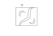
図4は、教師画像生成装置2の動作を示すフローチャートである。図5及び図6は、教師画像生成装置2の動作を説明する図である。具体的に、図5は、第1の画像処理が実行された後の1フレームの第1の教師画像WLIを示す図である。図6は、第2の画像処理が実行された後の1フレームの第2の教師画像IRを示す図である。なお、図6に示した第2の教師画像IRは、グレースケールで表現されており、黒に近付くにしたがって撮像された蛍光の成分の強度(輝度値に相当)が高い(輝度値が高い)ものである。
3. Operation of the teacher image generating device
Next, the operation of the teacher
Fig. 4 is a flowchart showing the operation of the teacher
先ず、制御部284は、第1,第2の光源221,222の時分割駆動を実行する(ステップS1A)。具体的に、制御部284は、ステップS1Aにおいて、同期信号に基づいて、交互に繰り返される第1,第2の期間のうち、第1の期間において第1の光源221から通常光(白色光)を出射させ、第2の期間において第2の光源222から近赤外励起光を出射させる。First, the control unit 284 executes time-division driving of the first and second
ステップS1Aの後、制御部284は、同期信号に基づいて、第1,第2の光源221,222の発光タイミングに同期させ、撮像素子242bに第1,第2の期間において第1,第2の被写体像をそれぞれ撮像させる(ステップS1B~S1D)。すなわち、撮像素子242bは、第1の期間である場合(ステップS1B:Yes)、言い換えれば、生体内に通常光(白色光)が照射された場合には、第1の被写体像(通常光)を撮像して第1の教師画像を生成する(ステップS1C)。一方、撮像素子242bは、第2の期間である場合(ステップS1B:No)、言い換えれば、生体内に近赤外励起光が照射された場合には、第2の被写体像(蛍光)を撮像して第2の教師画像を生成する(ステップS1D)。After step S1A, the control unit 284 synchronizes with the light emission timing of the first and second
ステップS1C,S1Dの後、メモリコントローラ283aは、同期信号に基づいて、メモリ282への教師画像の書込み及び読出しを制御する(ステップS1E)。
ステップS1Eの後、第1,第2の画像処理部283b,283cは、以下に示す処理を実行する(ステップS1F)。
すなわち、第1の画像処理部283bは、メモリコントローラ283aによってメモリ282から順次、読み出された各第1の教師画像に対して順次、第1の画像処理を実行する。そして、第1の画像処理部283bは、例えば、図5に示した第1の教師画像WLIを出力する。一方、第2の画像処理部283cは、メモリコントローラ283aによってメモリ282から順次、読み出された各第2の教師画像に対して順次、第2の画像処理を実行する。そして、第2の画像処理部283cは、例えば、図6に示した第2の教師画像IRを出力する。なお、第1,第2の教師画像は、同一の撮像素子242bにて撮像された画像であるため、図5及び図6に示した第1,第2の教師画像WLI,IRを比較して分かるように、同一の画像サイズを有している。すなわち、第1,第2の教師画像において、同一の画素位置は、同一の被写体における同一の位置を撮像した画素となっている。
After steps S1C and S1D, the memory controller 283a controls the writing and reading of the teacher image to and from the
After step S1E, the first and second
That is, the first
ステップS1Fの後、制御部284は、第3の通信部288の動作を制御し、当該ステップS1Fにて第1,第2の画像処理部283b,283cからそれぞれ出力される第1,第2の教師画像を一組とする教師画像を順次、学習装置3に送信する(ステップS1G)。
この後、制御部284は、ステップS1Aに戻る。
After step S1F, the control unit 284 controls the operation of the
Thereafter, the control unit 284 returns to step S1A.
〔3.学習装置の構成〕
次に、学習装置3の構成について説明する。
図7は、学習装置3の構成を示す図である。
学習装置3は、例えば、サーバ装置であり、教師画像生成装置2にて生成された教師画像を用いて学習モデルを生成する部分である。この学習装置3は、図7に示すように、通信部31と、制御部32と、記憶部33とを備える。
3. Configuration of the learning device
Next, the configuration of the learning device 3 will be described.
FIG. 7 is a diagram showing the configuration of the learning device 3.
The learning device 3 is, for example, a server device, and is a part that generates a learning model using a teacher image generated by the teacher
通信部31は、制御部32による制御の下、ネットワークNEを介して教師画像生成装置2(第3の通信部288)との間で情報の送受信を行う。
制御部32は、例えば、CPUやFPGA等を用いて構成され、学習装置3全体の動作を制御する。この制御部32は、教師画像取得部321と、特異領域特定部322と、第1の特徴量抽出部323と、特異対応領域学習部324とを備える。
なお、教師画像取得部321、特異領域特定部322、第1の特徴量抽出部323、及び特異対応領域学習部324の機能については、後述する「4.学習装置の動作」において説明する。
記憶部33は、制御部32が実行するプログラム、制御部32の処理に必要な情報、及び当該処理によって生成された情報等を記憶する。
The communication unit 31, under the control of the
The
The functions of the teacher
The
〔4.学習装置の動作〕
次に、上述した学習装置3の動作について説明する。
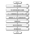
図8は、学習装置3の動作を示すフローチャートである。
先ず、教師画像取得部321は、通信部31を介して、教師画像生成装置2(第3の通信部288)から送信されてくる教師画像(第1,第2の教師画像)を順次、取得する(ステップS2A)。
4. Operation of the Learning Device
Next, the operation of the learning device 3 will be described.
FIG. 8 is a flowchart showing the operation of the learning device 3.
First, the teacher
ステップS2Aの後、特異領域特定部322は、第2の教師画像内の蛍光領域(特異領域)を特定する(ステップS2B)。
具体的に、特異領域特定部322は、第2の教師画像において、画素レベルが特定の閾値以上となる領域を蛍光領域として特定する。
ここで、当該画素レベルとしては、Y信号(輝度信号)に応じた輝度値やRGB値(画素値)を例示することができる。本実施の形態では、当該画素レベルとして、当該輝度値を採用している。すなわち、図6に示した第2の教師画像IRでは、輝度値が特定の閾値以上となる領域Arが蛍光領域として特定される。さらに、本実施の形態では、特異領域特定部322は、蛍光領域Arとして、輝度値が第1の範囲内となる第1の蛍光領域(第1の特異領域)Ar1(図6に示したグレーの部分)と、輝度値が当該第1の範囲よりも高い第2の範囲内となる第2の蛍光領域(第2の特異領域)Ar2(図6に示した黒の部分)とをそれぞれ特定する。
After step S2A, the peculiar
Specifically, the peculiar
Here, the pixel level can be exemplified by a luminance value or an RGB value (pixel value) according to a Y signal (luminance signal). In this embodiment, the luminance value is adopted as the pixel level. That is, in the second teacher image IR shown in FIG. 6, an area Ar in which the luminance value is equal to or greater than a specific threshold value is identified as a fluorescent area. Furthermore, in this embodiment, the peculiar
ステップS2Bの後、第1の特徴量抽出部323は、当該ステップS2Bにて蛍光領域が特定された第2の教師画像と組となる第1の教師画像内の蛍光対応領域(特異対応領域)と非対応領域との特徴量をそれぞれ抽出する(ステップS2C)。
ここで、蛍光対応領域とは、第1の教師画像内において、第2の教師画像の蛍光領域に対応する画素位置(当該蛍光領域と同一画素位置)の領域である。そして、非対応領域は、第1の教師画像内において、蛍光対応領域以外の領域である。本実施の形態では、蛍光対応領域は、第1の教師画像内において、第2の教師画像の第1の蛍光領域Ar1に対応する画素位置の第1の蛍光対応領域と、第2の教師画像の第2の蛍光領域Ar2に対応する画素位置の第2の蛍光対応領域とで構成される。すなわち、第1の特徴量抽出部323は、第1,第2の蛍光対応領域と非対応領域との特徴量をそれぞれ抽出する。
After step S2B, the first feature extraction unit 323 extracts features of the fluorescence-corresponding region (specific corresponding region) and non-corresponding region in the first teacher image paired with the second teacher image in which the fluorescent region was identified in step S2B (step S2C).
Here, the fluorescence corresponding region is a region in the first teacher image at a pixel position that corresponds to the fluorescent region of the second teacher image (the same pixel position as the fluorescent region). The non-corresponding region is a region in the first teacher image other than the fluorescence corresponding region. In this embodiment, the fluorescence corresponding region is composed of a first fluorescence corresponding region in the first teacher image at a pixel position that corresponds to the first fluorescent region Ar1 of the second teacher image, and a second fluorescence corresponding region in the pixel position that corresponds to the second fluorescent region Ar2 of the second teacher image. That is, the first feature amount extraction unit 323 extracts the feature amounts of the first and second fluorescence corresponding regions and the non-corresponding region, respectively.
また、第1の蛍光対応領域の特徴量としては、以下の(1)~(3)の抽出方法を例示することができる。
(1)第1の蛍光対応領域を構成する画素毎に特徴量を抽出する。
(2)第1の蛍光対応領域を構成する複数の画素を1つのグループとして、当該グループ毎に特徴量を抽出する。
(3)第1の蛍光対応領域全体の特徴量を抽出する。
なお、第2の蛍光対応領域の特徴量、及び非対応領域の特徴量の抽出方法も上記同様である。
As the feature amount of the first fluorescence corresponding region, the following extraction methods (1) to (3) can be exemplified.
(1) A feature amount is extracted for each pixel constituting the first fluorescence corresponding region.
(2) A plurality of pixels constituting the first fluorescence corresponding region is treated as one group, and a feature amount is extracted for each group.
(3) A feature amount of the entire first fluorescence corresponding region is extracted.
The method for extracting the feature amount of the second fluorescence-corresponding region and the feature amount of the non-corresponding region is the same as that described above.
さらに、特徴量としては、解像度、エッジ、色、明るさ、ノイズ、コントラスト、及びヒストグラム等に関する特徴量を例示することができる。 Furthermore, examples of features include features related to resolution, edges, color, brightness, noise, contrast, and histograms, etc.
ステップS2Cの後、特異対応領域学習部324は、第1の蛍光対応領域の特徴量と、第2の蛍光対応領域の特徴量と、非対応領域の特徴量とに基づいて、当該第1,第2の蛍光対応領域を機械学習して学習モデルを生成する(ステップS2D)。すなわち、当該学習モデルを用いれば、特徴量から、当該特徴量を有する領域が第1,第2の蛍光対応領域及び非対応領域のいずれの領域であるかを判別することができる。
ここで、機械学習としては、畳み込みニューラルネットワークを用いた機械学習(深層学習)を例示することができる。すなわち、当該機械学習では、第1,第2の教師画像を一組とする教師画像の数が増えれば増えるほど、第1,第2の蛍光対応領域及び非対応領域を精度よく判別可能な学習モデルを生成することができる。
本実施の形態では、特異対応領域学習部324は、第1,第2の蛍光対応領域を機械学習して学習モデルを生成する際、青の色成分に関する特徴量の重みを他の赤及び緑の色成分に関する特徴量の重みよりも低くする。例えば、当該青の色成分に関する特徴量を当該機械学習には用いない。
そして、特異対応領域学習部324は、生成した学習モデルを記憶部33に記憶する。
After step S2C, the peculiar corresponding region learning unit 324 performs machine learning of the first and second fluorescence corresponding regions based on the feature amount of the first fluorescence corresponding region, the feature amount of the second fluorescence corresponding region, and the feature amount of the non-corresponding region to generate a learning model (step S2D). In other words, by using the learning model, it is possible to determine whether a region having the feature amount is the first or second fluorescence corresponding region, or a non-corresponding region, based on the feature amount.
Here, an example of the machine learning is machine learning (deep learning) using a convolutional neural network. That is, in this machine learning, the more the number of teacher images each consisting of a first and second teacher image increases, the more accurately a learning model can be generated that can distinguish between the first and second fluorescence corresponding regions and non-corresponding regions.
In this embodiment, when generating a learning model by performing machine learning on the first and second fluorescence corresponding regions, the unique corresponding region learning unit 324 weights the feature amount related to the blue color component lower than the feature amounts related to the other red and green color components, and for example, does not use the feature amount related to the blue color component in the machine learning.
Then, the unique corresponding region learning unit 324 stores the generated learning model in the
〔5.医療用観察装置の構成〕
次に、学習装置3にて生成された学習モデルを用いて蛍光領域を推測する医療用観察装置4について説明する。
図9は、医療用観察装置4の構成を示す図である。図10は、カメラヘッド44及び制御装置48の構成を示す図である。
医療用観察装置4は、図9または図10に示すように、教師画像生成装置2と略同様の構成を有する。なお、医療用観察装置4において、教師画像生成装置2と同一の構成には同一の符号を付している。
以下では、医療用観察装置4の各構成のうち、教師画像生成装置2とは異なる構成について主に説明する。
5. Configuration of medical observation device
Next, the
Fig. 9 is a diagram showing the configuration of the
9 and 10, the
In the following, among the components of the
光源装置42は、医療用観察装置4において、教師画像生成装置2における光源装置22に対応した構成である。この光源装置42は、図9または図10に示すように、第1の光源221のみを備える。すなわち、光源装置42は、光源装置22とは異なり、第2の光源222を有していない。
そして、光源装置42では、制御装置48による制御の下、第1の光源221が駆動し、通常光(白色光)のみを出射する。
なお、本実施の形態では、光源装置42は、制御装置48とは別体で構成されているが、これに限らず、当該制御装置48内部に設けられた構成を採用しても構わない。
The light source device 42 in the
In the light source device 42, under the control of the
In the present embodiment, the light source device 42 is configured as a separate unit from the
カメラヘッド44は、医療用観察装置4において、教師画像生成装置2におけるカメラヘッド24に対応した構成である。このカメラヘッド44は、図10に示すように、光源装置42が第2の光源222を有していないことに伴い、カメラヘッド24から励起光カットフィルタ242aを省略した構成を有する。
そして、カメラヘッド44(撮像素子242b)は、制御装置48による制御の下、特定のフレーム周期で撮像を行う。以下では、第1の教師画像と区別するために、カメラヘッド44(撮像素子242b)により第1の被写体像(通常光)を撮像することで生成された画像を撮像画像と記載する。
The
Then, the camera head 44 (
制御装置48は、本開示に係る医療用画像処理装置に相当する。この制御装置48は、医療用観察装置4において、教師画像生成装置2における制御装置28に対応した構成である。この制御装置48では、図10に示すように、制御装置28に対して、画像生成部283及び制御部284の代わりに、画像生成部483及び制御部484が採用されている。
画像生成部483は、制御部484による制御の下、カメラヘッド44(第1の通信部243)から順次、出力され、第2の通信部281にて受信した撮像画像(RAW信号(デジタル信号))を処理する。この画像生成部483は、図10に示すように、メモリコントローラ483aと、画像処理部483bと、第2の特徴量抽出部483cと、特異対応領域特定部483dと、表示制御部483eとを備える。
なお、メモリコントローラ483a、画像処理部483b、第2の特徴量抽出部483c、特異対応領域特定部483d、及び表示制御部483eの機能については、後述する「6.医療用観察装置の動作」において説明する。
The
The
The functions of the
制御部484は、例えば、CPUやFPGA等を用いて構成され、第1~第3の伝送ケーブル25,27,29を介して制御信号を出力することで、光源装置42、カメラヘッド44、及び表示装置26の動作を制御するとともに、制御装置48全体の動作を制御する。
なお、当該制御部484の機能の一部については、後述する「6.医療用観察装置の動作」において説明する。
The control unit 484 is configured using, for example, a CPU, FPGA, etc., and controls the operation of the light source device 42, the
Some of the functions of the control unit 484 will be explained in "6. Operation of the medical observation device" below.
〔6.医療用観察装置の動作〕
次に、上述した医療用観察装置4の動作について説明する。
図11は、医療用観察装置4の動作を示すフローチャートである。図12は、医療用観察装置4の動作を説明する図である。具体的に、図12は、ステップS3Gにて生成される表示画像WLI´を示す図である。ここで、図12では、説明の便宜上、ステップS3Bにおいて図5に示した第1の教師画像WLIと同一の撮像画像が生成されたものとしている。
なお、以下で説明する医療用観察装置4の動作を実行する前に、制御部484は、第3の通信部288の動作を制御し、学習装置3から学習モデルを受信し、当該学習モデルを記憶部287に記憶しているものとする。
6. Operation of the medical observation device
Next, the operation of the above-mentioned
Fig. 11 is a flowchart showing the operation of the
It is assumed that, before executing the operation of the
先ず、制御部484は、光源装置42(第1の光源221)を駆動する(ステップS3A)。これにより、生体内(観察対象)に対して、通常光(白色光)が照射される。
ステップS3Aの後、制御部484は、特定のフレーム周期で、撮像素子242bに第1の被写体像(通常光)を撮像させ、撮像画像を生成する(ステップS3B)。
ステップS3Bの後、メモリコントローラ483aは、メモリ282への撮像画像の書込み及び読出しを制御する(ステップS3C)。具体的に、メモリコントローラ483aは、カメラヘッド44(第1の通信部243)から順次、出力され、第2の通信部281にて受信した撮像画像をメモリ282に順次、書き込む。また、メモリコントローラ483aは、メモリ282から撮像画像を特定のタイミングで読み出すとともに、当該読み出した撮像画像を画像処理部483bに入力させる。
First, the control unit 484 drives the light source device 42 (first light source 221) (step S3A), whereby normal light (white light) is irradiated onto the inside of the living body (observation target).
After step S3A, the control unit 484 causes the
After step S3B, the
ステップS3Cの後、画像処理部483bは、メモリコントローラ483aによってメモリ282から順次、読み出された各撮像画像に対して順次、上述した第1の画像処理を実行する(ステップS3D)。
ステップS3Dの後、第2の特徴量抽出部483cは、当該ステップS3Dにて画像処理部483bから順次、出力される撮像画像について、当該撮像画像の領域毎の特徴量を抽出する(ステップS3E)。
ここで、特徴量としては、以下の(4),(5)の抽出方法を例示することができる。
(4)撮像画像を構成する画素毎に特徴量を抽出する。
(5)撮像画像を構成する複数の画素を1つのグループ(領域)として、当該グループ毎に特徴量を抽出する。
また、第2の特徴量抽出部483cが抽出する特徴量は、第1の特徴量抽出部323が抽出する特徴量と同一種類の特徴量である。
After step S3C, the
After step S3D, the second feature
Here, the feature amount can be, for example, extracted by the following methods (4) and (5).
(4) A feature amount is extracted for each pixel constituting the captured image.
(5) A plurality of pixels constituting a captured image is treated as one group (region), and a feature amount is extracted for each group.
Moreover, the feature amount extracted by the second feature
ステップS3Eの後、特異対応領域特定部483dは、当該ステップS3Eにて抽出された特徴量に基づいて、記憶部287に記憶された学習モデルを用いて撮像画像内における第1,第2の蛍光対応領域を特定する(ステップS3F)。
ステップS3Fの後、表示制御部483eは、撮像画像内において、当該ステップS3Fにて特定された第1,第2の蛍光対応領域を他の領域と識別して表示する表示画像を生成する(ステップS3G)。例えば、ステップS3Bにおいて図5に示した第1の教師画像WLIと同一の撮像画像が生成されたものと仮定した場合には、図12に示すように、撮像画像内において、第1,第2の蛍光対応領域Ar1´,Ar2´(蛍光対応領域Ar´)を他の領域と識別した表示画像WLI´が生成される。当該識別する方法としては、撮像画像内において、蛍光対応領域Ar´に単色の色(例えば緑色等)を付す等を例示することができる。また、第2の蛍光領域Ar2は、上述したように、第1の蛍光領域Ar1よりも輝度値が高い領域である。このため、第2の蛍光対応領域Ar2´(図12では説明の便宜上、黒で表現)を第1の蛍光対応領域Ar1´(図12では説明の便宜上、グレーで表現)よりも濃い色を付すことが好ましい。
そして、表示制御部483eは、表示画像WLI´に応じた映像信号を生成し、第2の伝送ケーブル27を介して、当該映像信号を表示装置26に出力する。これにより、表示装置26は、当該表示画像WLI´を表示する。
After step S3E, the unique corresponding
After step S3F, the
Then, the
以上説明した本実施の形態によれば、以下の効果を奏する。
本実施の形態に係る学習装置3は、第1,第2の教師画像を一組とする教師画像を用い、第1の教師画像内における第2の教師画像内の蛍光領域に対応する画素位置の蛍光対応領域の特徴量に基づいて、当該蛍光対応領域を機械学習して学習モデルを生成する。
そして、本実施の形態に係る制御装置48は、生体内(観察対象)からの第1の被写体像(通常光)を撮像した撮像画像を取得し、当該撮像画像内の領域毎の特徴量に基づいて、上述した学習モデルを用いて当該撮像画像内における蛍光対応領域を特定する。
すなわち、学習モデルを用いることで蛍光領域を推測することができるため、生体内にインドシアニングリーン等の蛍光物質を投与する必要がない。したがって、利便性を向上させることができる。
また、医療用観察装置4において、生体内に近赤外励起光を照射する必要もないため、第2の光源222や励起光カットフィルタ242aを省略することができ、構成の簡素化及び小型化を図ることができる。
According to the present embodiment described above, the following effects are achieved.
The learning device 3 in this embodiment uses a pair of teacher images consisting of a first and a second teacher image, and performs machine learning of the fluorescence corresponding area based on the feature amounts of the fluorescence corresponding area at a pixel position in the first teacher image that corresponds to the fluorescent area in the second teacher image, to generate a learning model.
Then, the
In other words, since the fluorescent region can be predicted using the learning model, there is no need to administer fluorescent substances such as indocyanine green into the living body, thereby improving convenience.
Furthermore, in the
また、本実施の形態に係る学習装置3では、蛍光領域を輝度値の高さに応じて第1,第2の蛍光領域の2段階に分けている。当該蛍光領域に対応する蛍光対応領域も同様である。すなわち、制御装置48にて特定される蛍光対応領域も第1,第2の蛍光対応領域に分けられる。このため、医師等のユーザは、表示画像から、蛍光の成分の強度が高いと推測される部分と、蛍光の成分の強度が低いと推測される部分とを容易に認識することができる。
Furthermore, in the learning device 3 according to this embodiment, the fluorescent region is divided into two stages, a first and a second fluorescent region, according to the level of the luminance value. The same is true for the fluorescent corresponding region corresponding to the fluorescent region. That is, the fluorescent corresponding region identified by the
ところで、癌等の病変部を画像認識にて特定する際には、青の色成分の特徴量を考慮する必要がない。
本実施の形態に係る学習装置3では、蛍光対応領域を機械学習して学習モデルを生成する際、青の色成分に関する特徴量の重みを他の色成分に関する特徴量の重みよりも低くする。例えば、当該青の色成分に関する特徴量を当該機械学習には用いない。このため、不要な特徴量を考慮せずに機械学習することができるため、処理負荷を軽減することができる。
Incidentally, when identifying a lesion such as cancer by image recognition, it is not necessary to take into account the feature amount of the blue color component.
In the learning device 3 according to the present embodiment, when generating a learning model by machine learning the fluorescence corresponding region, the weight of the feature amount related to the blue color component is lowered than the weight of the feature amount related to the other color components. For example, the feature amount related to the blue color component is not used in the machine learning. Therefore, machine learning can be performed without taking unnecessary feature amounts into consideration, and the processing load can be reduced.
(その他の実施の形態)
ここまで、本開示を実施するための形態を説明してきたが、本開示は上述した実施の形態によってのみ限定されるべきものではない。
上述した実施の形態では、蛍光領域を輝度値の高さに応じて第1,第2の蛍光領域の2段階に分けていたが、これに限らず、蛍光領域を1つのみとしてもよく、あるいは、輝度値の高さに応じて3段階以上に分けても構わない。蛍光領域に対応する蛍光対応領域も同様である。
(Other embodiments)
Although the embodiments for carrying out the present disclosure have been described above, the present disclosure should not be limited to only the above-described embodiments.
In the above-described embodiment, the fluorescent region is divided into two stages, the first and second fluorescent regions, according to the level of the luminance value, but this is not limiting, and the fluorescent region may be only one, or may be divided into three or more stages according to the level of the luminance value. The same applies to the fluorescent corresponding region that corresponds to the fluorescent region.
上述した実施の形態では、第1の波長帯域の光を通常光(白色光)とし、第2の波長帯域の光を近赤外励起光としていたが、これに限らない。第1の波長帯域と第2の波長帯域とが異なっていれば、その他の光を採用しても構わない。この際、第1,第2の波長帯域は、一部が重複する帯域であってもよく、あるいは、全く重複しない帯域であっても構わない。
例えば、第2の波長帯域の光としては、所謂NBI(Narrow Band Imaging(狭帯域光観察))で用いる狭帯域光を採用しても構わない。この際、第1の波長帯域の光としては、通常光(白色光)でもよく、その他の光でも構わない。
In the above-described embodiment, the light in the first wavelength band is normal light (white light) and the light in the second wavelength band is near-infrared excitation light, but this is not limited thereto. As long as the first wavelength band and the second wavelength band are different, other light may be used. In this case, the first and second wavelength bands may be bands that partially overlap, or may not overlap at all.
For example, the light in the second wavelength band may be narrowband light used in so-called Narrow Band Imaging (NBI). In this case, the light in the first wavelength band may be normal light (white light) or other light.
ところで、従来、癌細胞を検出する癌診断法の一つである光線力学診断(Photo Dynamic Diagnosis:PDD)が知られている。
当該光線力学診断では、例えば5-アミノレブリン酸(以下、5-ALAと記載)等の光感受性物質が用いられる。当該5-ALAは、元来、動植物の生体内に含まれる天然アミノ酸である。この5-ALAは、体内投与後に細胞内に取り込まれ、ミトコンドリア内でプロトポルフィリンに生合成される。そして、癌細胞では、当該プロトポルフィリンが過剰に集積する。また、当該癌細胞に過剰集積するプロトポルフィリンは、光活性を有する。このため、当該プロトポルフィリンは、励起光(例えば375nm~445nmの波長帯域の青色可視光)で励起すると、蛍光(例えば600nm~740nmの波長帯域の赤色蛍光)を発光する。このように、光感受性物質を用いて癌細胞を蛍光発光させる癌診断法を光線力学診断という。
そして、上述した実施の形態において、第2の波長帯域の光として、プロトポルフィリンを励起する励起光(例えば375nm~445nmの波長帯域の青色可視光)を採用しても構わない。この際、第1の波長帯域の光としては、通常光(白色光)でもよく、その他の光でも構わない。
Incidentally, photodynamic diagnosis (PDD) is known as one of the cancer diagnostic methods for detecting cancer cells.
In the photodynamic diagnosis, a photosensitive substance such as 5-aminolevulinic acid (hereinafter, referred to as 5-ALA) is used. The 5-ALA is a natural amino acid that is originally contained in the living body of animals and plants. After administration to the body, the 5-ALA is taken up into cells and is biosynthesized into protoporphyrin in mitochondria. Then, the protoporphyrin accumulates excessively in cancer cells. Furthermore, the protoporphyrin that accumulates excessively in the cancer cells has photoactivity. Therefore, when the protoporphyrin is excited with excitation light (e.g., blue visible light in the wavelength band of 375 nm to 445 nm), it emits fluorescence (e.g., red fluorescence in the wavelength band of 600 nm to 740 nm). In this way, a cancer diagnosis method in which a photosensitive substance is used to make cancer cells emit fluorescence is called photodynamic diagnosis.
In the above-described embodiment, the light in the second wavelength band may be excitation light for exciting protoporphyrin (e.g., blue visible light in the wavelength band of 375 nm to 445 nm).In this case, the light in the first wavelength band may be normal light (white light) or other light.
上述した実施の形態では、第1,第2の教師画像を単体の撮像素子242bにて生成していたが、これに限らない。例えば、第1の被写体像と第2の被写体像とを分離し、2つの撮像素子にてそれぞれ撮像し、当該2つの撮像素子にて第1,第2の教師画像をそれぞれ生成する構成を採用しても構わない。この際、学習装置3は、第1,第2の教師画像間における画素の対応関係を認識している必要がある。In the above-described embodiment, the first and second teacher images are generated by a
上述した実施の形態では、教師画像生成装置2と学習装置3とをネットワークNEを介して互いに通信可能に接続する構成としていたが、これに限らず、教師画像生成装置2と学習装置3とを1つの装置として構成しても構わない。In the above-described embodiment, the teacher
上述した実施の形態では、挿入部21を硬性内視鏡で構成した医療用観察装置4に本開示に係る医療用画像処理装置を搭載していたが、これに限らない。例えば、挿入部21を軟性内視鏡で構成した医療用観察装置に本開示に係る医療用画像処理装置を搭載しても構わない。また、被写体内(生体内)や被写体表面(生体表面)の所定の視野領域を拡大して観察する手術用顕微鏡(例えば、特開2016-42981号公報参照)等の医療用観察装置に本開示に係る医療用画像処理装置を搭載しても構わない。
上述した実施の形態において、カメラヘッド44の一部の構成や制御装置48の一部の構成を例えばコネクタCN1やコネクタCN2に設けても構わない。
In the above-described embodiment, the medical image processing device according to the present disclosure is mounted on the
In the above-described embodiment, a part of the configuration of the
なお、以下のような構成も本開示の技術的範囲に属する。
(1)第1の波長帯域の光が照射された被検体からの光を撮像した第1の教師画像と、前記第1の波長帯域とは異なる第2の波長帯域の光が照射された前記被検体からの光を撮像した第2の教師画像とを一組とする教師画像を取得する教師画像取得部と、前記第2の教師画像内の特異領域を特定する特異領域特定部と、前記第1の教師画像内における前記特異領域に対応する画素位置の特異対応領域の特徴量を抽出する第1の特徴量抽出部と、前記特徴量に基づいて、前記特異対応領域を機械学習して学習モデルを生成する特異対応領域学習部とを備える学習装置。
(2)前記被検体は、前記第2の波長帯域の励起光が照射されることで蛍光を発する被検体であり、前記第2の教師画像は、前記励起光が照射された前記被検体からの前記蛍光を撮像した画像であり、前記特異領域特定部は、前記第2の教師画像において、前記蛍光の成分の強度が特定の閾値以上となる領域を前記特異領域として特定する前記(1)に記載の学習装置。
(3)前記特異領域特定部は、前記第2の教師画像において、画素レベルが特定の閾値以上となる領域を前記特異領域として特定する前記(1)または(2)に記載の学習装置。
(4)前記特異領域特定部は、前記特異領域として、画素レベルが第1の範囲内となる第1の特異領域と、画素レベルが前記第1の範囲よりも高い第2の範囲内となる第2の特異領域とをそれぞれ特定し、前記第1の特徴量抽出部は、前記第1の教師画像内における前記特異対応領域である前記第1の特異領域に対応する画素位置の第1の特異対応領域と、前記第1の教師画像内における前記特異対応領域である前記第2の特異領域に対応する画素位置の第2の特異対応領域との特徴量をそれぞれ抽出し、前記特異対応領域学習部は、前記特徴量に基づいて、前記第1の特異対応領域と前記第2の特異対応領域とをそれぞれ機械学習する前記(3)に記載の学習装置。
(5)前記特徴量は、色及び輝度の少なくとも一方に関する特徴量を含み、前記特異対応領域学習部は、前記特異対応領域を機械学習して学習モデルを生成する際、青の色成分に関する前記特徴量の重みを他の色成分に関する前記特徴量の重みよりも低くする前記(1)~(4)のいずれか一つに記載の学習装置。
(6)前記第1の波長帯域の光は、交互に繰り返される第1の期間と第2の期間とにおいて、前記第1の期間に発光した光であり、前記第2の波長帯域の光は、前記第2の期間に発光した光である前記(1)~(5)のいずれか一つに記載の学習装置。
(7)第1の波長帯域の光が照射された観察対象からの光を撮像した撮像画像を取得する撮像画像取得部と、前記撮像画像の領域毎の特徴量を抽出する第2の特徴量抽出部と、前記特徴量に基づいて、機械学習により構築された学習モデル用いて前記撮像画像内における特異対応領域を特定する特異対応領域特定部とを備え、前記学習モデルは、前記第1の波長帯域の光が照射された被検体からの光を撮像した第1の教師画像と、前記第1の波長帯域とは異なる第2の波長帯域の光が照射された前記被検体からの光を撮像した第2の教師画像とを一組とする教師画像を用い、前記第1の教師画像内における前記第2の教師画像内の特異領域に対応する画素位置の前記特異対応領域の特徴量に基づいて、前記特異対応領域を機械学習して生成された学習モデルである医療用画像処理装置。
(8)前記被検体は、前記第2の波長帯域の励起光が照射されることで蛍光を発する被検体であり、前記第2の教師画像は、前記励起光が照射された前記被検体からの前記蛍光を撮像した画像であり、前記特異領域は、前記第2の教師画像において、前記蛍光の成分の強度が特定の閾値以上となる領域である前記(7)に記載の医療用画像処理装置。
(9)前記特異領域は、前記第2の教師画像において、画素レベルが特定の閾値以上となる領域である前記(7)または(8)に記載の医療用画像処理装置。
(10)前記特異領域は、画素レベルが第1の範囲内となる第1の特異領域と、画素レベルが前記第1の範囲よりも高い第2の範囲内となる第2の特異領域とを含み、前記学習モデルは、前記第1の教師画像内における前記特異対応領域である前記第1の特異領域に対応する画素位置の第1の特異対応領域と、前記第1の教師画像内における前記特異対応領域である前記第2の特異領域に対応する画素位置の第2の特異対応領域との特徴量に基づいて、前記第1の特異対応領域と前記第2の特異対応領域とをそれぞれ機械学習して生成された学習モデルである前記(9)に記載の医療用画像処理装置。
(11)前記特徴量は、色及び輝度の少なくとも一方に関する特徴量を含み、前記学習モデルは、青の色成分に関する前記特徴量の重みを他の色成分に関する前記特徴量の重みを低くした状態で、前記特異対応領域を機械学習して生成された学習モデルである前記(7)~(10)のいずれか一つに記載の医療用画像処理装置。
(12)前記第1の波長帯域の光は、交互に繰り返される第1の期間と第2の期間とにおいて、前記第1の期間に発光した光であり、前記第2の波長帯域の光は、前記第2の期間に発光した光である前記(7)~(11)のいずれか一つに記載の医療用画像処理装置。
(13)前記撮像画像内において、前記特異対応領域を他の領域と識別して表示する表示画像を生成する表示制御部をさらに備える前記(7)~(12)のいずれか一つに記載の医療用画像処理装置。
Note that the following configurations also fall within the technical scope of the present disclosure.
(1) A learning device comprising: a teacher image acquisition unit that acquires a set of teacher images including a first teacher image that captures light from a subject irradiated with light in a first wavelength band and a second teacher image that captures light from the subject irradiated with light in a second wavelength band different from the first wavelength band; a peculiar region identification unit that identifies a peculiar region in the second teacher image; a first feature extraction unit that extracts features of a peculiar correspondence region at a pixel position in the first teacher image that corresponds to the peculiar region; and a peculiar correspondence region learning unit that performs machine learning of the peculiar correspondence region based on the features to generate a learning model.
(2) The learning device described in (1) above, wherein the subject is a subject that emits fluorescence when irradiated with excitation light of the second wavelength band, the second teacher image is an image capturing the fluorescence from the subject irradiated with the excitation light, and the peculiar region identification unit identifies, in the second teacher image, a region where the intensity of the fluorescent component is equal to or greater than a specific threshold as the peculiar region.
(3) The learning device according to (1) or (2), wherein the peculiar region identification unit identifies, in the second teacher image, a region in which a pixel level is equal to or higher than a specific threshold as the peculiar region.
(4) The learning device described in (3), wherein the peculiar region identification unit identifies, as the peculiar region, a first peculiar region having a pixel level within a first range and a second peculiar region having a pixel level within a second range higher than the first range; the first feature extraction unit extracts features of a first peculiar correspondence region at a pixel position corresponding to the first peculiar correspondence region in the first teacher image and a second peculiar correspondence region at a pixel position corresponding to the second peculiar correspondence region in the first teacher image; and the peculiar correspondence region learning unit machine-learns the first peculiar correspondence region and the second peculiar correspondence region based on the features.
(5) The learning device according to any one of (1) to (4), wherein the features include features relating to at least one of color and brightness, and the unique correspondence region learning unit, when performing machine learning on the unique correspondence region to generate a learning model, weights the features relating to the blue color component lower than weights the features relating to other color components.
(6) A learning device described in any one of (1) to (5), wherein the light of the first wavelength band is light emitted during a first period and a second period that are repeated alternately, and the light of the second wavelength band is light emitted during the second period.
(7) A medical image processing device comprising: an image acquisition unit that acquires an image obtained by capturing light from an object to be observed that is irradiated with light of a first wavelength band; a second feature extraction unit that extracts features for each region of the captured image; and a peculiar correspondence region identification unit that identifies a peculiar correspondence region in the captured image using a learning model constructed by machine learning based on the features, wherein the learning model uses a set of teacher images including a first teacher image that captures light from a subject irradiated with light of the first wavelength band and a second teacher image that captures light from the subject irradiated with light of a second wavelength band different from the first wavelength band, and is a learning model generated by machine learning the peculiar correspondence region based on the features of the peculiar correspondence region at a pixel position in the first teacher image that corresponds to the peculiar correspondence region in the second teacher image.
(8) The medical image processing device described in (7), wherein the subject is a subject that emits fluorescence when irradiated with excitation light of the second wavelength band, the second teacher image is an image capturing the fluorescence from the subject irradiated with the excitation light, and the peculiar region is a region in the second teacher image where the intensity of the fluorescent component is equal to or greater than a specific threshold value.
(9) The medical image processing device according to (7) or (8), wherein the peculiar region is a region in the second teacher image where the pixel level is equal to or higher than a specific threshold value.
(10) The medical image processing device described in (9), wherein the peculiar region includes a first peculiar region whose pixel level is within a first range and a second peculiar region whose pixel level is within a second range higher than the first range, and the learning model is a learning model generated by machine learning the first peculiar correspondence region and the second peculiar correspondence region based on feature amounts of a first peculiar correspondence region at a pixel position corresponding to the first peculiar correspondence region in the first teacher image, and a second peculiar correspondence region at a pixel position corresponding to the second peculiar correspondence region in the first teacher image.
(11) A medical image processing device described in any one of (7) to (10), wherein the features include features related to at least one of color and brightness, and the learning model is a learning model generated by machine learning the unique corresponding region with a weight for the features related to the blue color component being higher than that for the features related to other color components.
(12) A medical image processing device described in any one of (7) to (11), wherein the light of the first wavelength band is light emitted during a first period and a second period that are repeated alternately, and the light of the second wavelength band is light emitted during the second period.
(13) The medical image processing device described in any one of (7) to (12), further comprising a display control unit that generates a display image that distinguishes the peculiar corresponding region from other regions within the captured image and displays the peculiar corresponding region.
1 学習システム
2 教師画像生成装置
3 学習装置
4 医療用観察装置
21 挿入部
22,42 光源装置
23 ライトガイド
24,44 カメラヘッド
25 第1の伝送ケーブル
26 表示装置
27 第2の伝送ケーブル
28,48 制御装置
29 第3の伝送ケーブル
31 通信部
32 制御部
33 記憶部
211 接眼部
221 第1の光源
222 第2の光源
241 レンズユニット
242 撮像部
242a 励起光カットフィルタ
242b 撮像素子
242c 信号処理部
242d カラーフィルタ
243 第1の通信部
281 第2の通信部
282 メモリ
283 画像生成部
283a メモリコントローラ
283b 第1の画像処理部
283c 第2の画像処理部
283d 表示制御部
284,484 制御部
285 入力部
286 出力部
287 記憶部
288 第3の通信部
321 教師画像取得部
322 特異領域特定部
323 第1の特徴量抽出部
324 特異対応領域学習部
483 画像生成部
483a メモリコントローラ
483b 画像処理部
483c 第2の特徴量抽出部
483d 特異対応領域特定部
483e 表示制御部
Ar 蛍光領域
Ar´ 蛍光対応領域
Ar1 第1の蛍光領域
Ar1´ 第1の蛍光対応領域
Ar2 第2の蛍光領域
Ar2´ 第2の蛍光対応領域
CN1,CN2 コネクタ
IR 第2の教師画像
NE ネットワーク
WLI 第1の教師画像
WLI´ 表示画像
LIST OF SYMBOLS 1
Claims (9)
前記第2の教師画像内の特異領域を特定する特異領域特定部と、
前記第1の教師画像内における前記特異領域に対応する画素位置の特異対応領域の特徴量を抽出する第1の特徴量抽出部と、
前記特徴量に基づいて、前記特異対応領域を機械学習して学習モデルを生成する特異対応領域学習部とを備え、
前記特異領域特定部は、
前記第2の教師画像において、画素レベルが特定の閾値以上となる領域を前記特異領域として特定するとともに、前記特異領域として、画素レベルが第1の範囲内となる第1の特異領域と、画素レベルが前記第1の範囲よりも高い第2の範囲内となる第2の特異領域とをそれぞれ特定し、
前記第1の特徴量抽出部は、
前記第1の教師画像内における前記特異対応領域である前記第1の特異領域に対応する画素位置の第1の特異対応領域と、前記第1の教師画像内における前記特異対応領域である前記第2の特異領域に対応する画素位置の第2の特異対応領域との特徴量をそれぞれ抽出し、
前記特異対応領域学習部は、
前記特徴量に基づいて、前記第1の特異対応領域と前記第2の特異対応領域とをそれぞれ機械学習する学習装置。 a teacher image acquiring unit that acquires a pair of teacher images including a first teacher image obtained by capturing an image of light from a subject irradiated with light of a first wavelength band and a second teacher image obtained by capturing an image of light from the subject irradiated with light of a second wavelength band different from the first wavelength band;
a peculiar region identifying unit that identifies a peculiar region in the second teacher image;
a first feature amount extraction unit that extracts a feature amount of a peculiar corresponding region at a pixel position corresponding to the peculiar region in the first teacher image;
a peculiar corresponding region learning unit that performs machine learning on the peculiar corresponding region based on the feature amount to generate a learning model ;
The unique region identifying unit is
In the second teacher image, a region in which a pixel level is equal to or higher than a specific threshold is identified as the peculiar region, and a first peculiar region in which a pixel level is within a first range and a second peculiar region in which a pixel level is within a second range higher than the first range are identified as the peculiar region,
The first feature extraction unit is
extracting feature amounts of a first unique correspondence region at a pixel position corresponding to the first unique correspondence region, which is the unique correspondence region in the first teacher image, and a second unique correspondence region at a pixel position corresponding to the second unique correspondence region, which is the unique correspondence region in the first teacher image;
The unique corresponding region learning unit is
A learning device that performs machine learning to respectively generate the first unique corresponding region and the second unique corresponding region based on the feature amount .
前記第2の波長帯域の励起光が照射されることで蛍光を発する被検体であり、
前記第2の教師画像は、
前記励起光が照射された前記被検体からの前記蛍光を撮像した画像であり、
前記画素レベルは、
前記第2の教師画像における前記蛍光の成分の強度である請求項1に記載の学習装置。 The subject is
an object that emits fluorescence when irradiated with excitation light in the second wavelength band;
The second teacher image is
an image obtained by capturing the fluorescence from the subject irradiated with the excitation light;
The pixel level is
The learning device according to claim 1 , wherein the intensity is an intensity of the fluorescent light component in the second teacher image.
前記第2の教師画像内の特異領域を特定する特異領域特定部と、
前記第1の教師画像内における前記特異領域に対応する画素位置の特異対応領域の特徴量を抽出する第1の特徴量抽出部と、
前記特徴量に基づいて、前記特異対応領域を機械学習して学習モデルを生成する特異対応領域学習部とを備え、
前記特徴量は、
色及び輝度の少なくとも一方に関する特徴量を含み、
前記特異対応領域学習部は、
前記特異対応領域を機械学習して学習モデルを生成する際、青の色成分に関する前記特徴量の重みを他の色成分に関する前記特徴量の重みよりも低くする学習装置。 a teacher image acquiring unit that acquires a pair of teacher images including a first teacher image obtained by capturing an image of light from a subject irradiated with light of a first wavelength band and a second teacher image obtained by capturing an image of light from the subject irradiated with light of a second wavelength band different from the first wavelength band;
a peculiar region identifying unit that identifies a peculiar region in the second teacher image;
a first feature amount extraction unit that extracts a feature amount of a peculiar corresponding region at a pixel position corresponding to the peculiar region in the first teacher image;
a peculiar corresponding region learning unit that performs machine learning on the peculiar corresponding region based on the feature amount to generate a learning model;
The feature amount is
The feature amount includes at least one of color and brightness.
The unique corresponding region learning unit is
A learning device that, when performing machine learning on the unique corresponding region to generate a learning model, weights the feature amount relating to the blue color component lower than weights of the feature amounts relating to other color components.
交互に繰り返される第1の期間と第2の期間とにおいて、前記第1の期間に発光した光であり、
前記第2の波長帯域の光は、
前記第2の期間に発光した光である請求項1に記載の学習装置。 The light of the first wavelength band is
In a first period and a second period which are alternately repeated, light emitted in the first period is
The light of the second wavelength band is
2. The learning device according to claim 1, wherein the light emitted during the second period.
前記撮像画像の領域毎の特徴量を抽出する第2の特徴量抽出部と、
前記特徴量に基づいて、機械学習により構築された学習モデル用いて前記撮像画像内における特異対応領域を特定する特異対応領域特定部とを備え、
前記学習モデルは、
前記第1の波長帯域の光が照射された被検体からの光を撮像した第1の教師画像と、前記第1の波長帯域とは異なる第2の波長帯域の光が照射された前記被検体からの光を撮像した第2の教師画像とを一組とする教師画像を用い、前記第1の教師画像内における前記第2の教師画像内の特異領域に対応する画素位置の前記特異対応領域の特徴量に基づいて、前記特異対応領域を機械学習して生成された学習モデルであり、
前記特異領域は、
前記第2の教師画像において、画素レベルが特定の閾値以上となる領域であるとともに、画素レベルが第1の範囲内となる第1の特異領域と、画素レベルが前記第1の範囲よりも高い第2の範囲内となる第2の特異領域とを含み、
前記学習モデルは、
前記第1の教師画像内における前記特異対応領域である前記第1の特異領域に対応する画素位置の第1の特異対応領域と、前記第1の教師画像内における前記特異対応領域である前記第2の特異領域に対応する画素位置の第2の特異対応領域との特徴量に基づいて、前記第1の特異対応領域と前記第2の特異対応領域とをそれぞれ機械学習して生成された学習モデルである医療用画像処理装置。 an image acquisition unit that acquires an image by capturing light from an observation target irradiated with light of a first wavelength band;
a second feature amount extraction unit that extracts a feature amount for each region of the captured image;
a peculiar corresponding region identifying unit that identifies a peculiar corresponding region in the captured image using a learning model constructed by machine learning based on the feature amount,
The learning model is
a learning model generated by machine learning the peculiar correspondence region based on a feature amount of the peculiar correspondence region at a pixel position in the first teacher image that corresponds to the peculiar correspondence region in the second teacher image, using teacher images that are a set of a first teacher image obtained by capturing an image of light from an object irradiated with light in the first wavelength band and a second teacher image obtained by capturing an image of light from the object irradiated with light in a second wavelength band different from the first wavelength band ;
The specific region is
the second teacher image includes a first peculiar region in which a pixel level is equal to or higher than a specific threshold and the pixel level is within a first range, and a second peculiar region in which the pixel level is within a second range higher than the first range,
The learning model is
A medical image processing device, which is a learning model generated by machine learning the first unique correspondence region and the second unique correspondence region based on feature amounts of a first unique correspondence region at a pixel position corresponding to the first unique correspondence region, which is the unique correspondence region in the first teacher image, and a second unique correspondence region at a pixel position corresponding to the second unique correspondence region, which is the unique correspondence region in the first teacher image .
前記第2の波長帯域の励起光が照射されることで蛍光を発する被検体であり、
前記第2の教師画像は、
前記励起光が照射された前記被検体からの前記蛍光を撮像した画像であり、
前記画素レベルは、
前記第2の教師画像における前記蛍光の成分の強度である請求項5に記載の医療用画像処理装置。 The subject is
an object that emits fluorescence when irradiated with excitation light in the second wavelength band;
The second teacher image is
an image obtained by capturing the fluorescence from the subject irradiated with the excitation light;
The pixel level is
The medical image processing apparatus according to claim 5 , wherein the intensity is an intensity of the fluorescent light component in the second teacher image.
前記撮像画像の領域毎の特徴量を抽出する第2の特徴量抽出部と、
前記特徴量に基づいて、機械学習により構築された学習モデル用いて前記撮像画像内における特異対応領域を特定する特異対応領域特定部とを備え、
前記学習モデルは、
前記第1の波長帯域の光が照射された被検体からの光を撮像した第1の教師画像と、前記第1の波長帯域とは異なる第2の波長帯域の光が照射された前記被検体からの光を撮像した第2の教師画像とを一組とする教師画像を用い、前記第1の教師画像内における前記第2の教師画像内の特異領域に対応する画素位置の前記特異対応領域の特徴量に基づいて、前記特異対応領域を機械学習して生成された学習モデルであり、
前記特徴量は、
色及び輝度の少なくとも一方に関する特徴量を含み、
前記学習モデルは、
青の色成分に関する前記特徴量の重みを他の色成分に関する前記特徴量の重みを低くした状態で、前記特異対応領域を機械学習して生成された学習モデルである医療用画像処理装置。 an image acquisition unit that acquires an image by capturing light from an observation target irradiated with light of a first wavelength band;
a second feature amount extraction unit that extracts a feature amount for each region of the captured image;
a peculiar corresponding region identifying unit that identifies a peculiar corresponding region in the captured image using a learning model constructed by machine learning based on the feature amount,
The learning model is
a learning model generated by machine learning the peculiar correspondence region based on a feature amount of the peculiar correspondence region at a pixel position in the first teacher image that corresponds to the peculiar correspondence region in the second teacher image, using teacher images that are a set of a first teacher image obtained by capturing an image of light from an object irradiated with light in the first wavelength band and a second teacher image obtained by capturing an image of light from the object irradiated with light in a second wavelength band different from the first wavelength band;
The feature amount is
The feature amount includes at least one of color and brightness.
The learning model is
A medical image processing device in which the learning model is generated by machine learning the unique corresponding region while the weight of the feature amount related to the blue color component is increased and the weight of the feature amount related to the other color components is reduced.
交互に繰り返される第1の期間と第2の期間とにおいて、前記第1の期間に発光した光であり、
前記第2の波長帯域の光は、
前記第2の期間に発光した光である請求項5に記載の医療用画像処理装置。 The light of the first wavelength band is
In a first period and a second period which are alternately repeated, light emitted in the first period is
The light of the second wavelength band is
The medical image processing apparatus according to claim 5 , wherein the light emitted is during the second period.
Applications Claiming Priority (3)
| Application Number | Priority Date | Filing Date | Title |
|---|---|---|---|
| JP2020024944 | 2020-02-18 | ||
| JP2020024944 | 2020-02-18 | ||
| PCT/JP2021/004847 WO2021166749A1 (en) | 2020-02-18 | 2021-02-09 | Learning device and medical image processing device |
Publications (2)
| Publication Number | Publication Date |
|---|---|
| JPWO2021166749A1 JPWO2021166749A1 (en) | 2021-08-26 |
| JP7565331B2 true JP7565331B2 (en) | 2024-10-10 |
Family
ID=77391384
Family Applications (1)
| Application Number | Title | Priority Date | Filing Date |
|---|---|---|---|
| JP2022501828A Active JP7565331B2 (en) | 2020-02-18 | 2021-02-09 | Learning device and medical image processing device |
Country Status (5)
| Country | Link |
|---|---|
| US (1) | US12213643B2 (en) |
| EP (1) | EP4088642A4 (en) |
| JP (1) | JP7565331B2 (en) |
| CN (1) | CN115087386B (en) |
| WO (1) | WO2021166749A1 (en) |
Families Citing this family (2)
| Publication number | Priority date | Publication date | Assignee | Title |
|---|---|---|---|---|
| KR20240079009A (en) * | 2022-11-28 | 2024-06-04 | 현대자동차주식회사 | Active learning apparatus and method thereof |
| WO2025144715A1 (en) * | 2023-12-29 | 2025-07-03 | Ipg Photonics Corporation | Systems and methods for controlling laser treatments using reflected intensity signals |
Citations (3)
| Publication number | Priority date | Publication date | Assignee | Title |
|---|---|---|---|---|
| WO2020003991A1 (en) | 2018-06-28 | 2020-01-02 | 富士フイルム株式会社 | Medical image learning device, method, and program |
| WO2020017213A1 (en) | 2018-07-20 | 2020-01-23 | 富士フイルム株式会社 | Endoscope image recognition apparatus, endoscope image learning apparatus, endoscope image learning method and program |
| WO2020022027A1 (en) | 2018-07-26 | 2020-01-30 | 富士フイルム株式会社 | Learning device and learning method |
Family Cites Families (10)
| Publication number | Priority date | Publication date | Assignee | Title |
|---|---|---|---|---|
| JP6533358B2 (en) | 2013-08-06 | 2019-06-19 | 三菱電機エンジニアリング株式会社 | Imaging device |
| KR101463354B1 (en) * | 2013-10-22 | 2014-11-18 | 영남대학교 산학협력단 | Apparatus for target detection of hyperspectral image and method thereof |
| JP6339872B2 (en) * | 2014-06-24 | 2018-06-06 | オリンパス株式会社 | Image processing apparatus, endoscope system, and image processing method |
| JP6505393B2 (en) | 2014-08-21 | 2019-04-24 | ソニー・オリンパスメディカルソリューションズ株式会社 | Medical observation device and medical observation system |
| JP6721994B2 (en) * | 2015-04-30 | 2020-07-15 | ソニー・オリンパスメディカルソリューションズ株式会社 | Medical signal processing device and medical observation system |
| EP3176751B1 (en) * | 2015-12-01 | 2020-12-30 | Ricoh Company, Ltd. | Information processing device, information processing method, computer-readable recording medium, and inspection system |
| TW201902411A (en) | 2017-06-09 | 2019-01-16 | 多田智裕 | Disease diagnosis support method, diagnosis support system and diagnosis support program employing endoscopic image of digestive organ, and computer-readable recording medium having said diagnosis support program stored thereon |
| JP7042907B2 (en) * | 2018-05-28 | 2022-03-28 | 富士フイルム株式会社 | Training data collection device, training data collection method and program, training system, trained model, and endoscopic image processing device |
| JP6971934B2 (en) | 2018-08-10 | 2021-11-24 | 株式会社東芝 | Image processing device |
| JP7038641B2 (en) * | 2018-11-02 | 2022-03-18 | 富士フイルム株式会社 | Medical diagnosis support device, endoscopic system, and operation method |
-
2021
- 2021-02-09 WO PCT/JP2021/004847 patent/WO2021166749A1/en not_active Ceased
- 2021-02-09 EP EP21757983.8A patent/EP4088642A4/en active Pending
- 2021-02-09 US US17/798,570 patent/US12213643B2/en active Active
- 2021-02-09 JP JP2022501828A patent/JP7565331B2/en active Active
- 2021-02-09 CN CN202180014096.5A patent/CN115087386B/en active Active
Patent Citations (3)
| Publication number | Priority date | Publication date | Assignee | Title |
|---|---|---|---|---|
| WO2020003991A1 (en) | 2018-06-28 | 2020-01-02 | 富士フイルム株式会社 | Medical image learning device, method, and program |
| WO2020017213A1 (en) | 2018-07-20 | 2020-01-23 | 富士フイルム株式会社 | Endoscope image recognition apparatus, endoscope image learning apparatus, endoscope image learning method and program |
| WO2020022027A1 (en) | 2018-07-26 | 2020-01-30 | 富士フイルム株式会社 | Learning device and learning method |
Non-Patent Citations (1)
| Title |
|---|
| 太田雄大、外2名,テクスチャと色特徴を用いた機械学習による舌苔抽出,第36回日本医用画像工学会大会予稿集,2017年07月27日,p.332-335 |
Also Published As
| Publication number | Publication date |
|---|---|
| WO2021166749A1 (en) | 2021-08-26 |
| EP4088642A4 (en) | 2023-06-07 |
| JPWO2021166749A1 (en) | 2021-08-26 |
| US20230112628A1 (en) | 2023-04-13 |
| CN115087386A (en) | 2022-09-20 |
| EP4088642A1 (en) | 2022-11-16 |
| US12213643B2 (en) | 2025-02-04 |
| CN115087386B (en) | 2025-04-25 |
Similar Documents
| Publication | Publication Date | Title |
|---|---|---|
| EP2992805B1 (en) | Electronic endoscope system | |
| WO2016129062A1 (en) | Image processing device, endoscope system, imaging device, image processing method, and program | |
| US20240306883A1 (en) | Medical image processing apparatus and medical observation system | |
| JP7565331B2 (en) | Learning device and medical image processing device | |
| US20100130819A1 (en) | Endoscope apparatus and its control method | |
| JP7551465B2 (en) | Medical image processing device and medical observation system | |
| US11737646B2 (en) | Medical image processing device and medical observation system | |
| JP2025028292A (en) | Medical observation system, medical light source control device, and medical light source control method | |
| US10863149B2 (en) | Image processing apparatus, image processing method, and computer readable recording medium | |
| JP2025028293A (en) | Medical control device, medical control method, and medical observation system | |
| US20250387053A1 (en) | Medical light source device and medical observation system | |
| US12295553B2 (en) | Medical image processing apparatus and medical observation system | |
| JP7224963B2 (en) | Medical controller and medical observation system | |
| JP2021146198A (en) | Medical image processing device and medical observation system | |
| JP5224390B2 (en) | Endoscope apparatus and method for operating endoscope apparatus | |
| JP2021003347A (en) | Medical image processing device and medical observation system | |
| JP2021132812A (en) | Medical image processing device and medical observation system | |
| US10918269B2 (en) | Medical light source apparatus and medical observation system | |
| JP2023039245A (en) | Image processing device, image processing method, and program |
Legal Events
| Date | Code | Title | Description |
|---|---|---|---|
| A621 | Written request for application examination |
Free format text: JAPANESE INTERMEDIATE CODE: A621 Effective date: 20231221 |
|
| A131 | Notification of reasons for refusal |
Free format text: JAPANESE INTERMEDIATE CODE: A131 Effective date: 20240625 |
|
| A521 | Request for written amendment filed |
Free format text: JAPANESE INTERMEDIATE CODE: A523 Effective date: 20240816 |
|
| TRDD | Decision of grant or rejection written | ||
| A01 | Written decision to grant a patent or to grant a registration (utility model) |
Free format text: JAPANESE INTERMEDIATE CODE: A01 Effective date: 20240903 |
|
| A61 | First payment of annual fees (during grant procedure) |
Free format text: JAPANESE INTERMEDIATE CODE: A61 Effective date: 20240930 |
|
| R150 | Certificate of patent or registration of utility model |
Ref document number: 7565331 Country of ref document: JP Free format text: JAPANESE INTERMEDIATE CODE: R150 |