JP7561586B2 - Corrosion-resistant and gas-permeable liquid-contacting member and diaphragm valve using same - Google Patents
Corrosion-resistant and gas-permeable liquid-contacting member and diaphragm valve using same Download PDFInfo
- Publication number
- JP7561586B2 JP7561586B2 JP2020197927A JP2020197927A JP7561586B2 JP 7561586 B2 JP7561586 B2 JP 7561586B2 JP 2020197927 A JP2020197927 A JP 2020197927A JP 2020197927 A JP2020197927 A JP 2020197927A JP 7561586 B2 JP7561586 B2 JP 7561586B2
- Authority
- JP
- Japan
- Prior art keywords
- liquid
- resistant
- sheet layer
- gas
- contacting
- Prior art date
- Legal status (The legal status is an assumption and is not a legal conclusion. Google has not performed a legal analysis and makes no representation as to the accuracy of the status listed.)
- Active
Links
- 230000007797 corrosion Effects 0.000 title claims description 35
- 238000005260 corrosion Methods 0.000 title claims description 35
- 229920001971 elastomer Polymers 0.000 claims description 47
- 239000007788 liquid Substances 0.000 claims description 34
- 239000000126 substance Substances 0.000 claims description 33
- 229920005989 resin Polymers 0.000 claims description 27
- 239000011347 resin Substances 0.000 claims description 27
- 239000002033 PVDF binder Substances 0.000 claims description 21
- 229920002981 polyvinylidene fluoride Polymers 0.000 claims description 21
- -1 polytetrafluoroethylene Polymers 0.000 claims description 12
- TXEYQDLBPFQVAA-UHFFFAOYSA-N tetrafluoromethane Chemical compound FC(F)(F)F TXEYQDLBPFQVAA-UHFFFAOYSA-N 0.000 claims description 9
- 229920001343 polytetrafluoroethylene Polymers 0.000 claims description 8
- 239000004810 polytetrafluoroethylene Substances 0.000 claims description 8
- 238000002844 melting Methods 0.000 claims description 7
- 230000008018 melting Effects 0.000 claims description 7
- 229920000181 Ethylene propylene rubber Polymers 0.000 claims description 4
- 238000003825 pressing Methods 0.000 claims description 2
- 239000007789 gas Substances 0.000 description 23
- 230000006866 deterioration Effects 0.000 description 8
- 239000002184 metal Substances 0.000 description 8
- 239000000463 material Substances 0.000 description 7
- VEXZGXHMUGYJMC-UHFFFAOYSA-N Hydrochloric acid Chemical compound Cl VEXZGXHMUGYJMC-UHFFFAOYSA-N 0.000 description 6
- 230000002093 peripheral effect Effects 0.000 description 6
- 229920002943 EPDM rubber Polymers 0.000 description 5
- 230000000903 blocking effect Effects 0.000 description 4
- 238000005192 partition Methods 0.000 description 4
- 230000035699 permeability Effects 0.000 description 4
- 229920001577 copolymer Polymers 0.000 description 3
- 238000010586 diagram Methods 0.000 description 3
- 239000003814 drug Substances 0.000 description 3
- QWPPOHNGKGFGJK-UHFFFAOYSA-N hypochlorous acid Chemical compound ClO QWPPOHNGKGFGJK-UHFFFAOYSA-N 0.000 description 3
- QAOWNCQODCNURD-UHFFFAOYSA-N sulfuric acid Substances OS(O)(=O)=O QAOWNCQODCNURD-UHFFFAOYSA-N 0.000 description 3
- ZAMOUSCENKQFHK-UHFFFAOYSA-N Chlorine atom Chemical compound [Cl] ZAMOUSCENKQFHK-UHFFFAOYSA-N 0.000 description 2
- 229910052801 chlorine Inorganic materials 0.000 description 2
- 239000000460 chlorine Substances 0.000 description 2
- 230000000052 comparative effect Effects 0.000 description 2
- 239000013013 elastic material Substances 0.000 description 2
- 239000000806 elastomer Substances 0.000 description 2
- 238000005868 electrolysis reaction Methods 0.000 description 2
- 229910052736 halogen Inorganic materials 0.000 description 2
- 150000002367 halogens Chemical class 0.000 description 2
- 238000000034 method Methods 0.000 description 2
- 239000012466 permeate Substances 0.000 description 2
- 239000000047 product Substances 0.000 description 2
- 239000012783 reinforcing fiber Substances 0.000 description 2
- 150000003839 salts Chemical class 0.000 description 2
- XLYOFNOQVPJJNP-UHFFFAOYSA-N water Substances O XLYOFNOQVPJJNP-UHFFFAOYSA-N 0.000 description 2
- BQCIDUSAKPWEOX-UHFFFAOYSA-N 1,1-Difluoroethene Chemical compound FC(F)=C BQCIDUSAKPWEOX-UHFFFAOYSA-N 0.000 description 1
- 229920001780 ECTFE Polymers 0.000 description 1
- UFHFLCQGNIYNRP-UHFFFAOYSA-N Hydrogen Chemical compound [H][H] UFHFLCQGNIYNRP-UHFFFAOYSA-N 0.000 description 1
- 229920000800 acrylic rubber Polymers 0.000 description 1
- 230000002411 adverse Effects 0.000 description 1
- 229920005549 butyl rubber Polymers 0.000 description 1
- UUAGAQFQZIEFAH-UHFFFAOYSA-N chlorotrifluoroethylene Chemical group FC(F)=C(F)Cl UUAGAQFQZIEFAH-UHFFFAOYSA-N 0.000 description 1
- 229920006026 co-polymeric resin Polymers 0.000 description 1
- 230000000694 effects Effects 0.000 description 1
- 238000009713 electroplating Methods 0.000 description 1
- 229920000840 ethylene tetrafluoroethylene copolymer Polymers 0.000 description 1
- 239000012530 fluid Substances 0.000 description 1
- 229920001973 fluoroelastomer Polymers 0.000 description 1
- 239000000446 fuel Substances 0.000 description 1
- 229920001519 homopolymer Polymers 0.000 description 1
- 239000001257 hydrogen Substances 0.000 description 1
- 229910052739 hydrogen Inorganic materials 0.000 description 1
- 230000007774 longterm Effects 0.000 description 1
- 238000004519 manufacturing process Methods 0.000 description 1
- 239000012528 membrane Substances 0.000 description 1
- 229920013653 perfluoroalkoxyethylene Polymers 0.000 description 1
- 229920001084 poly(chloroprene) Polymers 0.000 description 1
- 229920002493 poly(chlorotrifluoroethylene) Polymers 0.000 description 1
- 229920000058 polyacrylate Polymers 0.000 description 1
- 239000005023 polychlorotrifluoroethylene (PCTFE) polymer Substances 0.000 description 1
- 229920000642 polymer Polymers 0.000 description 1
- 238000007789 sealing Methods 0.000 description 1
Images


Classifications
-
- Y—GENERAL TAGGING OF NEW TECHNOLOGICAL DEVELOPMENTS; GENERAL TAGGING OF CROSS-SECTIONAL TECHNOLOGIES SPANNING OVER SEVERAL SECTIONS OF THE IPC; TECHNICAL SUBJECTS COVERED BY FORMER USPC CROSS-REFERENCE ART COLLECTIONS [XRACs] AND DIGESTS
- Y02—TECHNOLOGIES OR APPLICATIONS FOR MITIGATION OR ADAPTATION AGAINST CLIMATE CHANGE
- Y02E—REDUCTION OF GREENHOUSE GAS [GHG] EMISSIONS, RELATED TO ENERGY GENERATION, TRANSMISSION OR DISTRIBUTION
- Y02E60/00—Enabling technologies; Technologies with a potential or indirect contribution to GHG emissions mitigation
- Y02E60/30—Hydrogen technology
- Y02E60/36—Hydrogen production from non-carbon containing sources, e.g. by water electrolysis
Landscapes
- Diaphragms And Bellows (AREA)
- Laminated Bodies (AREA)
Description
本発明は、耐食性・耐ガス透過性接液部材、及びそれを用いたダイヤフラムバルブに係り、特に、塩水、塩酸、濃硫酸、次亜塩素酸等の腐食性液体を取り扱う器械や機器、バルブ等に好適に用いられる耐食性・耐ガス透過性接液部材や、かかる腐食性液体の輸送配管ラインに使用されるダイヤフラムバルブに関するものである。 The present invention relates to a corrosion-resistant, gas-permeable liquid-contacting member and a diaphragm valve using the same, and in particular to a corrosion-resistant, gas-permeable liquid-contacting member suitable for use in instruments, devices, valves, etc. that handle corrosive liquids such as salt water, hydrochloric acid, concentrated sulfuric acid, and hypochlorous acid, and a diaphragm valve used in a piping line for transporting such corrosive liquids.
従来から、腐食性液体に対して耐食性を有する接液部材は、隔離用の膜板であるダイヤフラム等として、バルブ、燃料ポンプ、ガス圧力調整器、制御器械等において、内容物である液体に、作動流体や作動機構が直接に接触しないようにして、働かせる場合に使用されて来ており、中でも、耐食性接液部材をダイヤフラムとして用いて、それを、弁座に対して圧接又は離隔作動させることにより、腐食性液体(薬液)の流通の遮断又は許容を行なわしめるダイヤフラムバルブは、広く用いられているところである。 Conventionally, wetted parts that are corrosion-resistant to corrosive liquids have been used as diaphragms, which are isolating membranes, in valves, fuel pumps, gas pressure regulators, control devices, etc., when the working fluid or operating mechanism is not in direct contact with the liquid contents. Among these, diaphragm valves, which use a corrosion-resistant wetted part as a diaphragm and press it against or separate it from the valve seat to block or allow the flow of corrosive liquids (chemicals), are widely used.
ところで、そのような腐食性液体が接触せしめられる耐食性の接液部材としては、その耐久性を高めるべく、各種の提案が為されており、例えば、特開平9-196199号公報や特開平9-196200号公報等においては、腐食性液体に接触する側に、ポリテトラフルオロエチレンの如きパーフルオロカーボン系樹脂乃至はフッ素樹脂からなる接液シートと、この接液シートを裏打ちするエチレン-プロピレン-ジエンゴム(EPDM)の如きゴム状弾性体にて構成されるゴムシートとの積層体からなる、ダイヤフラムとしての耐食性接液部材が、提案されているのであるが、そのような二層構造とした従来の耐食性の接液部材にあっては、かかる腐食性液体による悪影響を長期に亘って充分に回避し得るものではなかったのである。 In order to improve the durability of the corrosion-resistant liquid contact member that comes into contact with such corrosive liquids, various proposals have been made. For example, Japanese Patent Laid-Open Publication Nos. 9-196199 and 9-196200 propose a corrosion-resistant liquid contact member as a diaphragm, which is a laminate of a liquid contact sheet made of a perfluorocarbon resin or a fluororesin such as polytetrafluoroethylene on the side that comes into contact with the corrosive liquid, and a rubber sheet made of a rubber-like elastic body such as ethylene-propylene-diene rubber (EPDM) that backs the liquid contact sheet. However, such a conventional corrosion-resistant liquid contact member with a two-layer structure was not able to sufficiently avoid the adverse effects of such corrosive liquids over the long term.
すなわち、ポリテトラフルオロエチレンからなる接液シート層は、良好な耐薬品性を有するものではあるが、電気めっき、2次電池、水素生産ライン、塩水の電解等の電解工程での使用において、塩酸、濃硫酸、次亜塩素酸等の如き腐食性薬液に曝されたときに、かかる薬液から発生する塩素等のハロゲンガスの如き腐食性ガスの透過を充分に遮断することが出来ず、そのために、かかる接液シート層を透過した腐食性ガスによって、かかる接液シート層の外側に位置する裏打ちゴム層の薬品劣化を惹起したり、更にはダイヤフラムバルブに用いられている金属部品の腐食性ガスによる薬品劣化が惹起される問題があり、そのために、ダイヤフラム部材として、その耐久性、ひいてはダイヤフラムバルブとしての耐久性が悪化する問題を内在するものであった。 That is, although the liquid-contacting sheet layer made of polytetrafluoroethylene has good chemical resistance, when it is exposed to corrosive chemicals such as hydrochloric acid, concentrated sulfuric acid, hypochlorous acid, etc. in electrolytic processes such as electroplating, secondary batteries, hydrogen production lines, and salt water electrolysis, it cannot adequately block the permeation of corrosive gases such as halogen gases such as chlorine generated from such chemicals. As a result, there is a problem that the corrosive gas that permeates the liquid-contacting sheet layer causes chemical deterioration of the backing rubber layer located on the outside of the liquid-contacting sheet layer, and furthermore, the corrosive gas causes chemical deterioration of the metal parts used in the diaphragm valve, which causes an inherent problem of deterioration in its durability as a diaphragm member, and ultimately the durability as a diaphragm valve.
ここにおいて、本発明は、かかる事情を背景にして為されたものであって、その解決課題とするところは、薬液に対する良好な耐薬品性を確保しつつ、かかる薬液から生じる腐食性ガスの透過を効果的に抑制乃至は阻止して、そのような腐食性ガスに基づくところの腐食を回避して、耐久性を効果的に向上せしめた耐食性・耐ガス透過性接液部材、及びそれをダイヤフラムとして用いたダイヤフラムバルブを、提供することにある。 The present invention has been made against the background of these circumstances, and the problem to be solved is to provide a corrosion-resistant, gas-permeable liquid-contacting member that effectively suppresses or prevents the permeation of corrosive gases generated from chemical solutions while maintaining good chemical resistance to the chemical solutions, thereby avoiding corrosion caused by such corrosive gases and effectively improving durability, and a diaphragm valve using the same as the diaphragm.
そして、本発明にあっては、かくの如き課題を解決するために、一方の側の面に薬液が接触せしめられるパーフルオロカーボン系樹脂からなる接液シート層と、かかる接液シート層の前記薬液が接触しない他方の側に配置された、引張弾性率が1000MPa以下のポリフッ化ビニリデン系樹脂からなる中間シート層と、該中間シート層の前記接液シート層とは反対側に配置された、ゴム弾性体からなるクッションゴム層との積層構造体にて構成されていることを特徴とする耐食性・耐ガス透過性接液部材を、その要旨とするものである。 In order to solve these problems, the gist of the present invention is a corrosion-resistant, gas-permeability-resistant liquid-contacting member that is characterized by being composed of a laminated structure including a liquid-contacting sheet layer made of a perfluorocarbon resin with one side surface that is brought into contact with the chemical solution, an intermediate sheet layer made of a polyvinylidene fluoride resin with a tensile modulus of elasticity of 1000 MPa or less that is arranged on the other side of the liquid-contacting sheet layer that is not in contact with the chemical solution, and a cushion rubber layer made of a rubber elastic body that is arranged on the opposite side of the intermediate sheet layer to the liquid-contacting sheet layer.
なお、このような本発明に従う耐食性・耐ガス透過性接液部材の好ましい態様の一つによれば、前記中間シート層を与えるポリフッ化ビニリデン系樹脂は、130~170℃の融点を有するものである。 In one preferred embodiment of the corrosion-resistant, gas-permeation-resistant liquid-contacting member according to the present invention, the polyvinylidene fluoride resin that provides the intermediate sheet layer has a melting point of 130 to 170°C.
また、かかる本発明に従う耐食性・耐ガス透過性接液部材の好ましい態様の他の一つによれば、前記接液シート層を与えるパーフルオロカーボン系樹脂は、ポリテトラフルオロエチレンである。 In another preferred embodiment of the corrosion-resistant, gas-permeability-resistant liquid-contacting member according to the present invention, the perfluorocarbon resin that provides the liquid-contacting sheet layer is polytetrafluoroethylene.
さらに、本発明に従う耐食性・耐ガス透過性接液部材は、望ましくは、前記クッションゴム層を与えるゴム弾性体として、エチレン-プロピレン系ゴムを用いている。 Furthermore, the corrosion-resistant and gas-permeation-resistant liquid-contacting member according to the present invention preferably uses ethylene-propylene rubber as the rubber elastic body that provides the cushion rubber layer.
更にまた、本発明に従う耐食性・耐ガス透過性接液部材の望ましい別の態様の一つによれば、前記積層構造体を与える前記接液シート層、前記中間シート層及び前記クッションゴム層が、それぞれ、所定の形状に成形されて、該積層構造体が、一定の形状を有する成形体として、構成されている。 Furthermore, according to another desirable aspect of the corrosion-resistant and gas-permeability-resistant liquid-contacting member of the present invention, the liquid-contacting sheet layer, the intermediate sheet layer, and the cushion rubber layer that form the laminated structure are each molded into a predetermined shape, and the laminated structure is configured as a molded body having a fixed shape.
加えて、本発明にあっては、好ましくは、前記耐食性・耐ガス透過性接液部材からなることを特徴とするダイヤフラム部材を、その要旨とするものである。 In addition, the gist of the present invention is preferably a diaphragm member that is made of the above-mentioned corrosion-resistant and gas-permeable impermeable liquid-contacting material.
また、本発明にあっては、望ましくは、前記耐食性・耐ガス透過性接液部材からなることを特徴とする弁座を、その要旨とするものである。 The gist of the present invention is preferably a valve seat made of the above-mentioned corrosion-resistant and gas-permeable liquid-contacting material.
そして、本発明にあっては、上述の如き構成の耐食性・耐ガス透過性接液部材が、弁座に対する圧接又は離間作動によって、薬液流路における薬液の遮断又は流通を行なうダイヤフラムとして用いられてなるダイヤフラムバルブをも、その要旨とするものである。 The gist of the present invention is also a diaphragm valve in which the corrosion-resistant, gas-permeable-resistant liquid-contacting member having the above-mentioned configuration is used as a diaphragm that blocks or allows the flow of chemicals in a chemical flow path by pressing against or separating from a valve seat.
なお、そのようなダイヤフラムバルブによって、流通又は遮断が行なわれる薬液としては、有利には、腐食性ガスを発生する液体がその対象とされ、更に、そのような腐食性ガスを発生する液体としては、好適には、電解工程において配管内を流通せしめられる塩酸、濃硫酸、次亜塩素酸等が、その対象とされるものである。 The chemical liquid that is allowed to flow or blocked by such a diaphragm valve is preferably a liquid that generates corrosive gas, and further, such liquids that generate corrosive gas are preferably hydrochloric acid, concentrated sulfuric acid, hypochlorous acid, etc., which are caused to flow through the piping in the electrolysis process.
このように、本発明に従う耐食性・耐ガス透過性接液部材にあっては、パーフルオロカーボン系樹脂からなる接液シート層とゴム弾性体からなるクッションゴム層との間に、引張弾性率が1000MPa以下のポリフッ化ビニリデン系樹脂からなる中間シート層が介在せしめられてなる積層構造体にて構成されているところから、腐食性ガスの透過が、かかる中間シート層の存在によって、効果的に遮断せしめられ得て、そのような腐食性ガスに基づくところの外側シート層の劣化が有利に阻止され得ることとなるのであり、これによって、耐食性・耐ガス透過性接液部材としての耐久性の向上が効果的に図られ得ると共に、周囲の金属部品の腐食を阻止して、その長寿命化が有利に図られ得ることとなる。しかも、中間シート層を与えるポリフッ化ビニリデン系樹脂の弾性率が、クッションゴム層を与えるゴム弾性体の弾性率に近づけられているところから、クッションゴム層のクッション性を接液シート層に効果的に伝達して、その作動機能を有利に奏せしめ得ることに加えて、中間シート層におけるマイクロクラックの発生を効果的に抑制乃至は阻止して、その低ガス透過性を長く維持して、耐久性を向上せしめることが出来るという特徴を発揮することが出来ることとなる。 Thus, the corrosion-resistant, gas-permeability-resistant liquid-contacting member according to the present invention is constructed as a laminated structure in which an intermediate sheet layer made of a polyvinylidene fluoride resin having a tensile modulus of elasticity of 1000 MPa or less is interposed between a liquid-contacting sheet layer made of a perfluorocarbon resin and a cushion rubber layer made of a rubber elastomer. Therefore, the presence of such intermediate sheet layer can effectively block the permeation of corrosive gases, and deterioration of the outer sheet layer due to such corrosive gases can be advantageously prevented. This effectively improves the durability of the corrosion-resistant, gas-permeability-resistant liquid-contacting member, and advantageously prevents corrosion of the surrounding metal parts, thereby extending their lifespan. Moreover, since the elastic modulus of the polyvinylidene fluoride resin that forms the intermediate sheet layer is close to the elastic modulus of the rubber elastomer that forms the cushion rubber layer, the cushioning properties of the cushion rubber layer are effectively transmitted to the liquid-contacting sheet layer, and the operating function can be advantageously exhibited. In addition, the occurrence of microcracks in the intermediate sheet layer is effectively suppressed or prevented, and the low gas permeability can be maintained for a long time, improving durability.
そして、そのような耐食性・耐ガス透過性接液部材を、特に、ダイヤフラムバルブにおける薬液の遮断又は流通を行なうダイヤフラムとして用いることにより、バルブとしての耐久性が著しく向上せしめられ得たダイヤフラムバルブが、有利に提供され得ることとなったのである。 By using such corrosion-resistant, gas-permeable liquid-contacting members, particularly as the diaphragm that blocks or allows the flow of chemicals in a diaphragm valve, it has become possible to advantageously provide a diaphragm valve in which the durability of the valve has been significantly improved.
以下、本発明を更に具体的に明らかにするために、本発明の実施の形態について、図面を参照しつつ、詳細に説明することとする。 In order to clarify the present invention more specifically, the following describes in detail the embodiments of the present invention with reference to the drawings.
先ず、図1には、本発明に従う耐食性・耐ガス透過性接液部材をダイヤフラムとして使用したダイヤフラムバルブの一例が、示されている。そこにおいて、ダイヤフラムバルブ10は、入口流路14と出口流路16とを備え、更に、それら流路14,16の中間に位置し、且つ流路を湾曲させる仕切壁18を備えると共に、かかる仕切壁18の先端面(上面)が弁座20とされてなる弁本体12を有している。また、かかる弁本体12の仕切壁18の上方に形成された開口部を覆蓋するように、ボンネット22が取り付けられて、このボンネット22に支承されたスピンドル24が、ハンドル26の回動操作によって、上下方向(軸方向)に移動可能とされている。そして、スピンドル24の下端部に固定されたコンプレッサ28に対して、中心部が取り付けられて、上下方向に変形移動可能とされた、円形又は略矩形の平面形態を呈するダイヤフラム30が、その周縁部において、弁本体12の開口周縁部とボンネット22の下端部との間に挟持せしめられることによって、弁本体12の開口部が閉塞せしめられるようになっている一方、スピンドル24の上下動、ひいてはコンプレッサ28の上下動によって、ダイヤフラム30の中心部が、弁座20に圧接又は離隔せしめられることによって、流路14,16を流れる液体の流れを遮断し、又は通過(流通)させ得るようになっているのである。
1 shows an example of a diaphragm valve using the corrosion-resistant and gas-permeable liquid-contacting member according to the present invention as a diaphragm. The
そして、このような構成のダイヤフラムバルブ10において、入口流路14と出口流路16との間を遮断又は連通させるダイヤフラム30が、図2に示される如く、本発明に従う耐食性・耐ガス透過性接液部材にて、構成されているのである。即ち、ダイヤフラム30は、一方の側の面(図においては、下面)に、流路(14,16)内を流通せしめられる薬液が接触させられることとなる、パーフルオロカーボン系樹脂からなる接液シート層32と、かかる接液シート層32の上記薬液が接触しない他方の側(図においては、上側)に配置された、引張弾性率が1000MPa以下のポリフッ化ビニリデン系樹脂からなる中間シート層34と、この中間シート層34の前記接液シート層32とは反対側に配置された、所定のゴム弾性体からなるクッションゴム層36との積層構造体にて、構成されているのである。なお、ここでは、それら接液シート層32、中間シート層34及びクッションゴム層36は、それぞれ、所定の形状に成形されてなる形態において積層され、その積層構造体が、一定の形状を有する成形体として構成されており、スピンドル24により引き上げられていない状況下においては、図2(a)に示される如き形態を呈するようになっている。また、接液シート層32は、その中央部が厚肉とされ、そこに、コンプレッサ28に取り付けるための連結金具38の基部が埋設されていると共に、かかる連結金具38は、中間シート層34の中央開口部を通じて、クッションゴム層36の中心部を貫通してなる形態において、上方に突出せしめられている。
In the
また、ダイヤフラム30においては、接液シート層32の接液側の面となる下面の周縁部に沿って、環状の周縁突条40が形成されていると共に、接液シート層32の中心部を通って直径方向に延びる線状突条42が一体的に設けられている。この周縁突条40は、ダイヤフラム30が弁本体12とボンネット22との間に挟持されたときに、弁本体12の開口周縁部との間のシール性を高めるためのものであり、また、線状突条42は、コンプレッサ28の下降作動によって、ダイヤフラム30が下方に変形移動せしめられて、弁本体12の弁座20に圧接せしめられたときに、弁座20との間の流体遮断性を向上せしめるためのものである。
In addition, the
なお、図2(a)に示されるダイヤフラム30は、その成形形態における組付け状態を示すものであって、通常、そのような形態において、ダイヤフラムバルブ10に組み付けられて、かかるダイヤフラム30の中心部がコンプレッサ28にて押圧されることにより、弁座20に圧接せしめられ、以て、入口流路14と出口流路16との間の液体の流通が、効果的に遮断され得るようになっているのである。また、コンプレッサ28が、スピンドル24の軸方向への移動によって上方に移動せしめられると、ダイヤフラム30は、図2(b)に示されるように、上方に引き上げられてなる、上方への湾曲(突出)形態において変形せしめられることとなる。そして、そのような形態においては、ダイヤフラム30は、図1に示される如く、弁座20に圧接されることはなく、所定の間隔を隔てて、離隔せしめられることとなるところから、入口流路14と出口流路16との間に、所定の液体が流通され得るようになるのである。
The
ところで、かかるダイヤフラム30において、薬液に接触することとなる接液シート層32は、一般に、0.8~4.5mm程度の厚さにおいて形成されるものであって、そして、その材質としては、かかる薬液に対する耐食性を確保するために、ポリテトラフルオロエチレンや、テトラフルオロエチレン-パーフルオロ(アルキルビニルエーテル)共重合体、テトラフルオロエチレン-ヘキサフルオロプロピレン共重合体、エチレン-テトラフルオロエチレン共重合体、エチレン-クロロトリフルオロエチレン共重合体、ポリクロロトリフルオロエチレン重合体、テトラフルオロエチレン-パーフルオロアルコキシエチレン共重合樹脂等の如き、公知の各種のパーフルオロカーボン系樹脂が適宜に選択されることとなるが、特に、本発明にあっては、ポリテトラフルオロエチレンが、好適に用いられることとなる。
In the
また、そのような接液シート層32を裏打ちするクッションゴム層36は、コンプレッサ28の動作を、接液シート層32に有効に伝達させるためのものであって、一般に、2~15mm程度の厚さにおいて形成され、そして、その材質としては、特に制限されるものではなく、公知のゴム弾性を有する材質が適宜に採用され、例えば、EPDM等のエチレン・プロピレンゴム、アクリルゴム、フッ素ゴム、ブチルゴム、クロロプレンゴム等を挙げることが出来るが、中でも、エチレン・プロピレン系ゴム、特にEPDMが、好適に用いられることとなる。
The
そして、それら接液シート層32とクッションゴム層36との間に介在せしめられる中間シート層34は、接液シート層32の薄肉部位を透過する腐食性ガスを遮断して、クッションゴム層36の劣化等を回避するためのものであって、引張弾性率が1000MPa以下のポリフッ化ビニリデン系樹脂にて構成されている。そこで、ポリフッ化ビニリデン系樹脂としては、ポリフッ化ビニリデン(ホモポリマー)が有利に用いられるところであるが、フッ化ビニリデンにヘキサフルオロプロピレンやテトラフルオロエチレン、クロロトリフルオロエチレン等のハロゲン化コモノマーを共重合させてなる、公知のフッ化ビニリデン系共重合体を用いることも可能である。そして、そのようなポリフッ化ビニリデン系樹脂は、1000MPa以下の引張弾性率を有している必要があり、これによって、中間シート層34にマイクロクラックが惹起されるのを効果的に阻止して、その低ガス透過性を長く維持することが可能となるのである。なお、そのような引張弾性率の下限は、一般に650MPa程度である。また、かかる引張弾性率は、JIS-K-7161:2014に従って求められるものである。
The
なお、かくの如き引張弾性率を有するポリフッ化ビニリデン系樹脂は、市場において入手可能であり、例えば、株式会社クレハやソルベイジャパン株式会社等から市販されているものが、適宜に採用されるところである。そして、そのような市販のポリフッ化ビニリデン系樹脂を用いて、所定の中間シート層34が成形されることとなるのであるが、そのような中間シート層34は、一般に0.3~1.5mm程度の厚さにおいて形成されることとなる。また、例示のダイヤフラム30において、中間シート層34は、接液シート層32の中心部の厚肉部上には存在しないように、中心部に開口部が設けられてなる形態において、形成されている。そのような開口部を中間シート層34に設けても、そこには、厚肉の接液シート層32が存在し、また、その厚肉部位には、連結金具38の下部フランジ部が存在することによって、腐食性ガスの透過は充分に抑制乃至は阻止され得ることとなるからである。但し、腐食性ガスの濃度によっては、スピンドル等の金属部品を保護するために、厚肉部の上部まで覆うような形状でもよい。
Polyvinylidene fluoride resins having such a tensile modulus are available on the market, and those commercially available from, for example, Kureha Corporation or Solvay Japan Co., Ltd. are appropriately adopted. A predetermined
また、かかる中間シート層34を構成するポリフッ化ビニリデン系樹脂は、好ましくは130~170℃、より好ましくは140~160℃の融点を有していることが望ましく、これによって、中間シート層34としての特徴を有利に発揮させることが可能となる。なお、このポリフッ化ビニリデン系樹脂の融点が、130℃よりも低くなるとガスの透過率が高くなり、更に140℃よりも低くなると、流動性が高くなり、中間シート層34の形成に際して、製品寸法がばらつく等の問題を惹起し易くなり、また、かかる融点が160℃を超えるようになると、中間シート層34にマイクロクラックが発生し易くなり、更には170℃を超えると弾性率が高くなり、バルブの操作トルクが重くなる等の問題が、惹起されるようになる。
In addition, it is desirable that the polyvinylidene fluoride resin constituting the
このように、本発明に従うダイヤフラム30は、接液シート層32とクッションゴム層36との間に、引張弾性率が1000MPa以下のポリフッ化ビニリデン系樹脂からなる中間シート層34を設けてなるものであるが、そこにおいて、中間シート層34が、1000MPa以下の引張弾性率を有する必要があることは、以下の比較実験結果からも、容易に理解され得るところである。
In this way, the
すなわち、比較試験は、図2に示される如き、3層構造の積層成形体からなるダイヤフラム30において、中間シート層34として、引張弾性率が750~850MPaであるポリフッ化ビニリデン(融点:148~154℃)にて形成したもの(n=5)と、引張弾性率が1800MPaであるポリフッ化ビニリデン(融点:173℃)にて形成したものとを用い、それぞれ、25mm及び50mmのダイヤフラムサイズ(口径)において、それらを、図1に示されるダイヤフラムバルブ10にセットして、その開閉試験を行ない、かかるダイヤフラム30における中間シート層34に、マイクロクラックが発生するまでの開閉回数を測定することにより、実施した。
In other words, the comparative test was carried out by using a
なお、かかるバルブ開閉試験は、開閉サイクル操作圧:0.4MPa、1分間の開作動、1分間の閉作動の条件下において、繰返し実施し、所定回数の開閉操作後に、バルブを分解して、ダイヤフラム30における中間シート層34の状態を調べ、更にその後、ダイヤフラム30、更にはダイヤフラムバルブ10を再度組み立てて、その開閉試験を続行して、かかる中間シート層34にマイクロクラックが発生するまでの回数を測定し、その結果を、下記表1に示した。また、このバルブ開閉試験は、流路(14,16)に薬液が存在していない状態下において(空気の存在下)、実施された。更に、接液シート層32は、ポリテトラフルオロエチレンがその材質とされる一方、クッションゴム層36は、EPDMがその材質とされてなるものであった。
The valve opening and closing test was repeatedly performed under the conditions of an opening and closing cycle operating pressure of 0.4 MPa, 1 minute of opening and closing, and 1 minute of closing. After a predetermined number of opening and closing operations, the valve was disassembled to check the state of the

かかる表1の結果より明らかな如く、本発明に従って、ダイヤフラム30を構成する接液シート層32とクッションゴム層36との間に介在せしめられる中間シート層34の材質として、引張弾性率が1000MPa以下のポリフッ化ビニリデン系樹脂が用いられていることにより、中間シート層34におけるマイクロクラックの発生が効果的に抑制され得ることとなるのであり、これによって、ポリフッ化ビニリデン系樹脂の優れた耐薬品特性や低ガス透過特性を、有利に確保しつつ、マイクロクラックの発生を長期間に亘って阻止して、そのようなマイクロクラックを通じての、塩素の如きハロゲンガス等の腐食性ガスの透過により、クッションゴム層36の劣化、更には、そのようなダイヤフラム30の周りに配置される金属部品の腐食性ガスによる薬品劣化を効果的に抑制乃至は防止し、以て、耐久性に優れたダイヤフラム30、更にはダイヤフラムバルブ10が、有利に提供され得ることとなるのである。
As is clear from the results in Table 1, in accordance with the present invention, the
また、本発明に従う耐食性・耐ガス透過性接液部材は、上述の如きダイヤフラムバルブ10におけるダイヤフラム30の他にも、各種の機器や器械等において、腐食性の薬液に接触する各種の部材として、好適に使用され得るものであって、例えば、図3に示される如きバタフライバルブにおける弁座(バルブシート)としても、有利に用いられ得るものである。
The corrosion-resistant, gas-permeability-resistant liquid-contacting member according to the present invention can be suitably used as various members that come into contact with corrosive chemicals in various devices and equipment, in addition to the
具体的には、図3に示されるバタフライバルブ50は、薬液の流路内に位置せしめられる開口部を有するバルブ本体52と、このバルブ本体52内に装入されて、軸回りに回動せしめられるステム54と、このステム54に一体的に設けられて、バルブ本体52の薬液流路内に位置する開口部内において回動せしめられることによって、かかる開口部の開放又は遮断を行なう円盤形状のディスク56とを有し、更に、かかるバルブ本体52の開口部の周縁部を覆うように取り付けられた弁座60とを含んで、構成されている。なお、ディスク56の薬液に接する両側の表面には、ポリテトラフルオロエチレンからなるライナー58が、所定厚さにおいて、それぞれ、設けられている。また、図3に示されるディスク56の配設形態は、薬液流路に配置されるバルブ本体52の開口部を閉塞する状態、従って薬液の流通を遮断する状態を示しており、このディスク56が約90°回動せしめられることによって、バルブ本体52の開口部は、全開状態(薬液の流通状態)となるようになっている。
Specifically, the
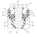
そして、ディスク56がその外周部において着座せしめられる弁座60は、図4に拡大して示されるように、薬液流路における薬液に接触せしめられることとなる接液シート層62と、この接液シート層62の内側に位置する中間シート層64と、更に、この中間シート層64の内側に位置するクッションゴム層66との所定形状の積層構造体にて構成され、このような積層形態において、バルブ本体52の開口部の内周縁部の全体を取り囲むように、円環状形態において配設されているのである。なお、かかる弁座60において、接液シート層62は、本発明に従って、パーフルオロカーボン系樹脂にて構成され、また、中間シート層64にあっても、引張弾性率が1000MPa以下のポリフッ化ビニリデン系樹脂にて構成されており、更に、クッションゴム層66は、所定のゴム弾性体にて構成されている。
The
従って、このような構成のバタフライバルブ50において、薬液の流通を阻止すべく、ステム54がその軸回りに回動せしめられて、ディスク56が、図3に示される如き位置に配置されることにより、ディスク56の外周部における膨出部56a,56a上に設けられたライナー58が、弁座60における円環状の接液シート層62に対して、その全周に亘って当接せしめられることとなるのであり、これによって、バルブ本体52における開口部の閉鎖が実現されることとなるのである。その際、弁座60には、クッションゴム層66が設けられていることによって、接液シート層62は、ディスク56の周縁部に対して、所定の圧力をもって弾性的に当接し、弁座60とディスク56との間に間隙が生じないようにして、より有効な薬液の流通の遮断が行なわれることとなるのであるが、そこでは、接液シート層62とクッションゴム層66との間に、本発明に従う中間シート層64が介在せしめられており、それによって、薬液から生じる腐食性ガスが接液シート層62を透過しても、クッションゴム層66に至るようなことが効果的に抑制乃至は阻止されることとなるのであり、以て、腐食性ガスによるクッションゴム層66の劣化が効果的に阻止され得て、その耐久性が有利に向上せしめられ得ることとなるのである。
Therefore, in a
以上、本発明の代表的な実施形態について詳述してきたが、それは、あくまでも、例示に過ぎないものであって、本発明は、そのような実施形態に係る具体的な記述によって、何等限定的に解釈されるものではないことが、理解されるべきである。 Although typical embodiments of the present invention have been described above in detail, it should be understood that these are merely examples, and that the present invention should not be interpreted in any way as being limited by the specific descriptions of such embodiments.
例えば、上述せるダイヤフラムバルブ10やバタフライバルブ50は、本発明に従う耐食性・耐ガス透過性接液部材が有利に用いられ得るものの例として挙げられているのであるが、その他の機器や器械等にも、同様に適用され得るものであることは、言うまでもないところであり、そして、例示のダイヤフラムバルブ10やバタフライバルブ50にあっても、例示の構造のみならず、公知の各種のダイヤフラムバルブやバタフライバルブの構造に適用可能であることは、言うまでもないところである。
For example, the above-mentioned
また、例示のダイヤフラムバルブ10におけるダイヤフラム30を構成する接液シート層32、中間シート層34及びクッションゴム層36や、バタフライバルブ50における弁座(バルブシート)60を構成する接液シート層62、中間シート層64及びクッションゴム層66は、何れも、別個に成形された後、積層されて、3層構造の積層体として用いられているのであるが、それら接液シート層32,62と中間シート層34,64とクッションゴム層36,66とを相互に固着一体化してなる形態の積層構造において、用いることも可能である。
The liquid-contacting
さらに、それら接液シート層32,62、中間シート層34,64及びクッションゴム層36,66のうちの少なくも何れか一層を、所定の製品形状に成形することなく、平坦なシート状形態のままにおいて、用いることも可能である。 Furthermore, at least one of the liquid-contacting sheet layers 32, 62, the intermediate sheet layers 34, 64, and the cushion rubber layers 36, 66 can be used in a flat sheet form without being molded into a specific product shape.
加えて、クッションゴム層36,66は、ゴム弾性体のみにて構成される他、ゴム弾性体内に補強繊維を混在させたり、補強繊維層を介在させて、クッションゴム層36,66の補強を行なうことも可能である。 In addition, the cushion rubber layers 36, 66 may be made of rubber elastic material only, or it may be possible to reinforce the cushion rubber layers 36, 66 by mixing reinforcing fibers into the rubber elastic material or by inserting a reinforcing fiber layer.
更にまた、例示のダイヤフラムバルブ10におけるコンプレッサ28の駆動形式にあっても、例示の如きハンドル26の手動による回動操作に代えて、空気圧による空圧駆動方式やモータ等による電気駆動方式も採用可能であり、その駆動形式には、公知のものが適宜に採用されることとなる。
Furthermore, in the drive system of the
10 ダイヤフラムバルブ 12 弁本体 14 入口流路 16 出口流路 18 仕切壁 20,60 弁座 22 ボンネット 24 スピンドル 26 ハンドル 28 コンプレッサ 30 ダイヤフラム 32,62 接液シート層 34,64 中間シート層 36,66 クッションゴム層 38 連結金具 40 周縁突条 42 線状突条 50 バタフライバルブ 52 バルブ本体 54 ステム 56 ディスク 58 ライナー
10
Claims (8)
A diaphragm valve comprising a corrosion-resistant and gas-permeability-resistant liquid-contacting member according to any one of claims 1 to 5 as a diaphragm that blocks or allows flow of a chemical in a chemical flow path by pressing against or separating from a valve seat.
Priority Applications (1)
| Application Number | Priority Date | Filing Date | Title |
|---|---|---|---|
| JP2020197927A JP7561586B2 (en) | 2020-11-30 | 2020-11-30 | Corrosion-resistant and gas-permeable liquid-contacting member and diaphragm valve using same |
Applications Claiming Priority (1)
| Application Number | Priority Date | Filing Date | Title |
|---|---|---|---|
| JP2020197927A JP7561586B2 (en) | 2020-11-30 | 2020-11-30 | Corrosion-resistant and gas-permeable liquid-contacting member and diaphragm valve using same |
Publications (2)
| Publication Number | Publication Date |
|---|---|
| JP2022086098A JP2022086098A (en) | 2022-06-09 |
| JP7561586B2 true JP7561586B2 (en) | 2024-10-04 |
Family
ID=81893804
Family Applications (1)
| Application Number | Title | Priority Date | Filing Date |
|---|---|---|---|
| JP2020197927A Active JP7561586B2 (en) | 2020-11-30 | 2020-11-30 | Corrosion-resistant and gas-permeable liquid-contacting member and diaphragm valve using same |
Country Status (1)
| Country | Link |
|---|---|
| JP (1) | JP7561586B2 (en) |
Families Citing this family (1)
| Publication number | Priority date | Publication date | Assignee | Title |
|---|---|---|---|---|
| JP2023070756A (en) * | 2021-11-10 | 2023-05-22 | 旭有機材株式会社 | Diaphragm member and diaphragm valve using the same |
Citations (2)
| Publication number | Priority date | Publication date | Assignee | Title |
|---|---|---|---|---|
| JP2013227870A (en) | 2012-04-24 | 2013-11-07 | Nitto Denko Corp | Diaphragm and reciprocating pump |
| WO2018043003A1 (en) | 2016-08-30 | 2018-03-08 | ダイキン工業株式会社 | Process for producing modified molded article, molded article, diaphragm, and diaphragm valve |
-
2020
- 2020-11-30 JP JP2020197927A patent/JP7561586B2/en active Active
Patent Citations (2)
| Publication number | Priority date | Publication date | Assignee | Title |
|---|---|---|---|---|
| JP2013227870A (en) | 2012-04-24 | 2013-11-07 | Nitto Denko Corp | Diaphragm and reciprocating pump |
| WO2018043003A1 (en) | 2016-08-30 | 2018-03-08 | ダイキン工業株式会社 | Process for producing modified molded article, molded article, diaphragm, and diaphragm valve |
Also Published As
| Publication number | Publication date |
|---|---|
| JP2022086098A (en) | 2022-06-09 |
Similar Documents
| Publication | Publication Date | Title |
|---|---|---|
| JP2011058509A (en) | Butterfly valve | |
| JPH0794168A (en) | Battery replacement device | |
| JP7561586B2 (en) | Corrosion-resistant and gas-permeable liquid-contacting member and diaphragm valve using same | |
| JP5126995B2 (en) | Composite sealing material | |
| CN1906436A (en) | Valve | |
| US6142173A (en) | High purity corrosion resistant butterfly valve | |
| JP2016205616A (en) | Check valve | |
| US6575431B2 (en) | Weir-type diaphragm valve with raised arcuate bead | |
| WO2006107005A1 (en) | Butterfly valve | |
| JP6616200B2 (en) | Sanitary valve structure, sanitary safety valve, sanitary inline relief valve and sanitary back pressure valve using the valve structure | |
| JP6639900B2 (en) | Soft seat type disc seatless seal valve | |
| WO2023085221A1 (en) | Diaphragm member and diaphragm valve using same | |
| JP2008298178A (en) | Piping member made of resin | |
| JPH0771628A (en) | All metal diaphragm valve | |
| JP7830234B2 (en) | Diaphragm valve | |
| JP4807573B2 (en) | Diaphragm valve | |
| JP4266618B2 (en) | valve | |
| JP6738741B2 (en) | Lining type butterfly valve | |
| JP2021127821A (en) | Diaphragm valve | |
| JP2022087724A (en) | Diaphragm valve | |
| JPH09196199A (en) | Diaphragm valve | |
| JP2020165491A (en) | Diaphragm valve | |
| JP2021127816A (en) | Diaphragm valve | |
| KR20230152091A (en) | Seal structure and seal material | |
| JP2020153393A (en) | Manufacturing method of diaphragm unit, diaphragm valve, and diaphragm unit |
Legal Events
| Date | Code | Title | Description |
|---|---|---|---|
| A621 | Written request for application examination |
Free format text: JAPANESE INTERMEDIATE CODE: A621 Effective date: 20231006 |
|
| A977 | Report on retrieval |
Free format text: JAPANESE INTERMEDIATE CODE: A971007 Effective date: 20240523 |
|
| A131 | Notification of reasons for refusal |
Free format text: JAPANESE INTERMEDIATE CODE: A131 Effective date: 20240528 |
|
| A521 | Request for written amendment filed |
Free format text: JAPANESE INTERMEDIATE CODE: A523 Effective date: 20240716 |
|
| TRDD | Decision of grant or rejection written | ||
| A01 | Written decision to grant a patent or to grant a registration (utility model) |
Free format text: JAPANESE INTERMEDIATE CODE: A01 Effective date: 20240910 |
|
| A61 | First payment of annual fees (during grant procedure) |
Free format text: JAPANESE INTERMEDIATE CODE: A61 Effective date: 20240924 |
|
| R150 | Certificate of patent or registration of utility model |
Ref document number: 7561586 Country of ref document: JP Free format text: JAPANESE INTERMEDIATE CODE: R150 |