JP7561569B2 - Ultrasonic Probe - Google Patents
Ultrasonic Probe Download PDFInfo
- Publication number
- JP7561569B2 JP7561569B2 JP2020177100A JP2020177100A JP7561569B2 JP 7561569 B2 JP7561569 B2 JP 7561569B2 JP 2020177100 A JP2020177100 A JP 2020177100A JP 2020177100 A JP2020177100 A JP 2020177100A JP 7561569 B2 JP7561569 B2 JP 7561569B2
- Authority
- JP
- Japan
- Prior art keywords
- mode
- wiring
- multiplexer
- transducers
- switch
- Prior art date
- Legal status (The legal status is an assumption and is not a legal conclusion. Google has not performed a legal analysis and makes no representation as to the accuracy of the status listed.)
- Active
Links
Images


Classifications
-
- A—HUMAN NECESSITIES
- A61—MEDICAL OR VETERINARY SCIENCE; HYGIENE
- A61B—DIAGNOSIS; SURGERY; IDENTIFICATION
- A61B8/00—Diagnosis using ultrasonic, sonic or infrasonic waves
- A61B8/44—Constructional features of the ultrasonic, sonic or infrasonic diagnostic device
- A61B8/4483—Constructional features of the ultrasonic, sonic or infrasonic diagnostic device characterised by features of the ultrasound transducer
- A61B8/4488—Constructional features of the ultrasonic, sonic or infrasonic diagnostic device characterised by features of the ultrasound transducer the transducer being a phased array
-
- A—HUMAN NECESSITIES
- A61—MEDICAL OR VETERINARY SCIENCE; HYGIENE
- A61B—DIAGNOSIS; SURGERY; IDENTIFICATION
- A61B8/00—Diagnosis using ultrasonic, sonic or infrasonic waves
- A61B8/54—Control of the diagnostic device
-
- B—PERFORMING OPERATIONS; TRANSPORTING
- B06—GENERATING OR TRANSMITTING MECHANICAL VIBRATIONS IN GENERAL
- B06B—METHODS OR APPARATUS FOR GENERATING OR TRANSMITTING MECHANICAL VIBRATIONS OF INFRASONIC, SONIC, OR ULTRASONIC FREQUENCY, e.g. FOR PERFORMING MECHANICAL WORK IN GENERAL
- B06B1/00—Methods or apparatus for generating mechanical vibrations of infrasonic, sonic, or ultrasonic frequency
- B06B1/02—Methods or apparatus for generating mechanical vibrations of infrasonic, sonic, or ultrasonic frequency making use of electrical energy
- B06B1/0292—Electrostatic transducers, e.g. electret-type
-
- B—PERFORMING OPERATIONS; TRANSPORTING
- B06—GENERATING OR TRANSMITTING MECHANICAL VIBRATIONS IN GENERAL
- B06B—METHODS OR APPARATUS FOR GENERATING OR TRANSMITTING MECHANICAL VIBRATIONS OF INFRASONIC, SONIC, OR ULTRASONIC FREQUENCY, e.g. FOR PERFORMING MECHANICAL WORK IN GENERAL
- B06B1/00—Methods or apparatus for generating mechanical vibrations of infrasonic, sonic, or ultrasonic frequency
- B06B1/02—Methods or apparatus for generating mechanical vibrations of infrasonic, sonic, or ultrasonic frequency making use of electrical energy
- B06B1/06—Methods or apparatus for generating mechanical vibrations of infrasonic, sonic, or ultrasonic frequency making use of electrical energy operating with piezoelectric effect or with electrostriction
- B06B1/0607—Methods or apparatus for generating mechanical vibrations of infrasonic, sonic, or ultrasonic frequency making use of electrical energy operating with piezoelectric effect or with electrostriction using multiple elements
- B06B1/0622—Methods or apparatus for generating mechanical vibrations of infrasonic, sonic, or ultrasonic frequency making use of electrical energy operating with piezoelectric effect or with electrostriction using multiple elements on one surface
-
- A—HUMAN NECESSITIES
- A61—MEDICAL OR VETERINARY SCIENCE; HYGIENE
- A61B—DIAGNOSIS; SURGERY; IDENTIFICATION
- A61B8/00—Diagnosis using ultrasonic, sonic or infrasonic waves
- A61B8/48—Diagnostic techniques
- A61B8/488—Diagnostic techniques involving Doppler signals
-
- B—PERFORMING OPERATIONS; TRANSPORTING
- B06—GENERATING OR TRANSMITTING MECHANICAL VIBRATIONS IN GENERAL
- B06B—METHODS OR APPARATUS FOR GENERATING OR TRANSMITTING MECHANICAL VIBRATIONS OF INFRASONIC, SONIC, OR ULTRASONIC FREQUENCY, e.g. FOR PERFORMING MECHANICAL WORK IN GENERAL
- B06B2201/00—Indexing scheme associated with B06B1/0207 for details covered by B06B1/0207 but not provided for in any of its subgroups
- B06B2201/70—Specific application
- B06B2201/76—Medical, dental
Landscapes
- Health & Medical Sciences (AREA)
- Life Sciences & Earth Sciences (AREA)
- Engineering & Computer Science (AREA)
- Heart & Thoracic Surgery (AREA)
- Molecular Biology (AREA)
- Biophysics (AREA)
- Nuclear Medicine, Radiotherapy & Molecular Imaging (AREA)
- Pathology (AREA)
- Radiology & Medical Imaging (AREA)
- Biomedical Technology (AREA)
- Veterinary Medicine (AREA)
- Medical Informatics (AREA)
- Physics & Mathematics (AREA)
- Surgery (AREA)
- Animal Behavior & Ethology (AREA)
- General Health & Medical Sciences (AREA)
- Public Health (AREA)
- Mechanical Engineering (AREA)
- Gynecology & Obstetrics (AREA)
- Ultra Sonic Daignosis Equipment (AREA)
Description
本発明は、超音波探触子(ultrasound probe)の技術に関し、特に、2次元アレイ型の超音波探触子の技術に関する。 The present invention relates to ultrasound probe technology, and in particular to two-dimensional array type ultrasound probe technology.
超音波探触子は、超音波診断装置等を構成する要素である。近年では、3次元立体画像を得られる超音波診断装置の開発が進んでいる。3次元の撮像のためには、超音波探触子内の複数の超音波振動子を2次元アレイとして配置する必要がある。2次元アレイ超音波探触子を用いた超音波信号の送受信の方式(モードと記載する場合がある)には、いわゆるBモードと呼ばれる撮像モードや、連続波ドプラモード等の各種がある。この探触子は、連続波ドプラモードでは、各振動子からの連続波ドプラ受信信号を処理する。なお、振動子とそれに接続される回路や信号線を、まとめて振動子チャネルと記載する場合がある。この探触子は、Bモードでは、例えば複数の受信信号の整相加算等を行う。整相は、遅延によって位相を調整することである。 An ultrasound probe is an element that constitutes an ultrasound diagnostic device. In recent years, ultrasound diagnostic devices capable of obtaining three-dimensional stereoscopic images have been developed. To obtain three-dimensional imaging, it is necessary to arrange multiple ultrasound transducers in an ultrasound probe as a two-dimensional array. There are various methods (sometimes referred to as modes) for transmitting and receiving ultrasound signals using a two-dimensional array ultrasound probe, such as an imaging mode called B-mode and a continuous wave Doppler mode. In the continuous wave Doppler mode, this probe processes the continuous wave Doppler reception signal from each transducer. Note that the transducers and the circuits and signal lines connected to them may be collectively referred to as transducer channels. In the B-mode, this probe performs, for example, phasing and addition of multiple reception signals. Phasing is adjusting the phase by delaying.
2次元アレイ超音波探触子に係わる先行技術例としては、特開2011-142931号公報(特許文献1)が挙げられる。特許文献1には、超音波プローブとして、連続波ドプラモードにおいて広いダイナミックレンジを確保しつつプローブケーブル内の信号線の本数が低減する旨が記載されている。
An example of prior art related to a two-dimensional array ultrasound probe is JP 2011-142931 A (Patent Document 1).
2次元アレイ超音波探触子の構成では、搭載する振動子数が、従来の1次元配列の超音波探触子に対し、2乗で増加する。しかし、この振動子数の2乗での増加に応じて、探触子と本体装置とを接続するケーブル(対応する信号線)の本数を2乗で増加させることは、困難である。そのため、対策の1つとしては、探触子内の回路で、多数の受信信号を整相加算等によってより少数の受信信号に減らして出力し、より少数のケーブルで本体装置に伝送する構成が挙げられる。このような構成を実現するには、探触子に搭載されるIC等の回路において、超音波の送受信および整相加算等の機能を実装する必要がある。この回路内では、振動子毎に一対一でその機能に対応する送受信回路等を配置し接続する必要がある。2次元アレイの振動子数は、例えば数千から1万以上の多数となる。この場合、ICでは、その多数の振動子数に応じた多数の送受信回路等を搭載する必要がある。そのうちの受信回路では、多数の受信信号を、整相加算によって、出力のケーブル数に合わせた数まで減らす必要がある。これらの実現に際し、2次元アレイ超音波探触子に搭載する回路の規模の大型化や高密度実装の難しさ等の課題がある。 In the configuration of a two-dimensional array ultrasonic probe, the number of transducers mounted increases quadratically compared to a conventional one-dimensional array ultrasonic probe. However, it is difficult to increase the number of cables (corresponding signal lines) connecting the probe and the main unit quadratically in accordance with the squared increase in the number of transducers. Therefore, one of the countermeasures is to reduce a large number of received signals to a smaller number of received signals by phasing and adding, etc. in the circuit in the probe, output them, and transmit them to the main unit through a smaller number of cables. To realize such a configuration, it is necessary to implement functions such as ultrasonic transmission and reception and phasing and adding in the circuit such as an IC mounted on the probe. In this circuit, it is necessary to arrange and connect a transmission and reception circuit, etc. that corresponds to the function for each transducer one-to-one. The number of transducers in a two-dimensional array can be many, for example, from several thousand to more than 10,000. In this case, the IC needs to be equipped with a large number of transmission and reception circuits, etc. corresponding to the large number of transducers. In the reception circuit, it is necessary to reduce a large number of received signals to a number that matches the number of output cables by phasing and adding. In order to achieve these goals, there are challenges, such as the large size of the circuits to be mounted on the two-dimensional array ultrasound probe and the difficulty of high-density implementation.
一方で、2次元アレイ超音波探触子は、連続波ドプラモードの場合、連続波を常時送信する必要があるため、アレイでのICの消費電力が大きくなりがちである。特に、ICの回路の規模が大きい場合や、増幅器等のアクティブ回路を多く使用する場合には、消費電力が大きくなる。消費電力の増加は、探触子の発熱につながる。探触子は、生体表面に接触して利用されるので、発熱が大きいと火傷等につながる。 On the other hand, when using a 2D array ultrasound probe in continuous wave Doppler mode, it is necessary to constantly transmit continuous waves, which tends to result in high power consumption by the IC in the array. Power consumption is particularly high when the IC circuit is large or when many active circuits such as amplifiers are used. Increased power consumption leads to heat generation in the probe. As the probe is used in contact with the surface of the living body, excessive heat generation can lead to burns, etc.
上記2次元アレイ超音波探触子は、連続波ドプラモードとそれ以外のBモード等のモードとの両方に対応できる高度な機能を備える構成が望ましい。しかし、そのためには、従来技術例では、上記のように回路規模や消費電力等の観点で課題があり、検討の余地がある。 It is desirable for the above-mentioned two-dimensional array ultrasound probe to have a configuration with advanced functions that can handle both continuous wave Doppler mode and other modes such as B mode. However, in order to achieve this, the conventional technology has issues in terms of circuit size, power consumption, etc., as described above, and there is room for further consideration.
本発明の目的は、2次元アレイ超音波探触子の技術に関して、連続波ドプラモードとそれ以外のモードとの少なくとも2種類のモードでの受信動作が可能であり、かつ、回路規模や消費電力の低減を実現できる技術を提供することである。 The objective of the present invention is to provide a two-dimensional array ultrasound probe technology that is capable of receiving in at least two modes, a continuous wave Doppler mode and another mode, and that can achieve a reduction in circuit size and power consumption.
本発明のうち代表的な実施の形態は以下に示す構成を有する。実施の形態の超音波探触子は、複数の振動子が2次元アレイとして配置されている超音波探触子であって、連続波ドプラモードである第1モードと、前記連続波ドプラモード以外のモードである第2モードとの少なくとも2種類のモードで超音波受信動作が可能であり、前記2次元アレイの一方の次元の方向を第1方向とし、他方の次元の方向を第2方向とし、前記複数の振動子の振動子毎に配置されている受信回路と、前記受信回路毎に接続されるように配置されている第1マルチプレクサと、前記第1マルチプレクサと接続されて前記第1方向に延在するように配置されている複数の第1配線と、前記2次元アレイの外側において、前記複数の第1配線と接続されて前記第2方向に延在するように配置されている第2配線と、前記第2配線上に配置され、前記複数の振動子の受信信号についての整相加算の単位に対応させて切断可能であるスイッチと、前記第2配線に接続されている、複数の第2マルチプレクサと、前記複数の第2マルチプレクサに接続されている、前記第1モードで使用される複数の第1出力ポートと、前記第2配線上の前記スイッチ間の部分毎に接続されている、前記第2モードで使用される複数の第2出力ポートと、を備える。 A representative embodiment of the present invention has the following configuration. The ultrasound probe of the embodiment is an ultrasound probe in which a plurality of transducers are arranged in a two-dimensional array, and is capable of ultrasound reception in at least two modes, a first mode which is a continuous wave Doppler mode, and a second mode which is a mode other than the continuous wave Doppler mode, and the direction of one dimension of the two-dimensional array is a first direction and the direction of the other dimension is a second direction, and includes a receiving circuit arranged for each transducer of the plurality of transducers, a first multiplexer arranged to be connected to each receiving circuit, and a first multiplexer arranged to be connected to the first multiplexer and extend in the first direction. The two-dimensional array includes a plurality of first wirings, a second wiring arranged outside the two-dimensional array so as to be connected to the plurality of first wirings and extend in the second direction, a switch arranged on the second wiring and capable of being disconnected in accordance with a unit of phasing and summation for the reception signals of the plurality of transducers, a plurality of second multiplexers connected to the second wiring, a plurality of first output ports used in the first mode connected to the plurality of second multiplexers, and a plurality of second output ports used in the second mode connected to each portion between the switches on the second wiring.
本発明のうち代表的な実施の形態によれば、2次元アレイ超音波探触子の技術に関して、連続波ドプラモードとそれ以外のモードとの少なくとも2種類のモードでの受信動作が可能であり、かつ、回路規模や消費電力の低減を実現できる。上記以外の課題、構成および効果等については、発明を実施するための形態において説明される。 According to a representative embodiment of the present invention, the technology of a two-dimensional array ultrasound probe enables reception in at least two modes, a continuous wave Doppler mode and another mode, and also enables reduction in circuit size and power consumption. Problems, configurations, effects, etc. other than those mentioned above are described in the description of the embodiment of the invention.
以下、図面を参照しながら本発明の実施の形態を詳細に説明する。図面において、同一部には原則として同一符号を付し、繰り返しの説明を省略する。実施の形態は、例示であって、適宜に説明が省略される。本発明は、他の種々の形態でも実施が可能である。特に限定しない場合、各構成要素は、単数でも複数でもよい。同一あるいは同様の構成要素が複数ある場合には、同一の符号に異なる添字を付して説明する場合がある。図面において、各構成要素の表現は、発明の理解を容易にするために、実際の位置、大きさ、形状、および範囲等を表していない場合があり、本発明は、図面に開示された位置、大きさ、形状、および範囲等には必ずしも限定されない。また、各種の要素について識別するためのデータや情報は、識別情報、識別子、ID、名、番号等の表現で説明する場合があるが、これらの表現は互いに置換可能である。 The following describes the embodiments of the present invention in detail with reference to the drawings. In the drawings, the same parts are generally given the same reference numerals, and repeated explanations are omitted. The embodiments are merely illustrative, and explanations are omitted as appropriate. The present invention can be implemented in various other forms. Unless otherwise specified, each component may be singular or plural. When there are a plurality of identical or similar components, they may be described with different subscripts added to the same reference numeral. In the drawings, the representation of each component may not represent the actual position, size, shape, range, etc., in order to facilitate understanding of the invention, and the present invention is not necessarily limited to the position, size, shape, range, etc., disclosed in the drawings. In addition, data and information for identifying various elements may be described using expressions such as identification information, identifiers, IDs, names, numbers, etc., but these expressions are interchangeable.
説明上、プログラムによる処理について説明する場合に、プログラムや機能や処理部等を主体として説明する場合があるが、それらについてのハードウェアとしての主体は、プロセッサ、あるいはプロセッサ等で構成されるコントローラ、装置、計算機、システム等である。計算機は、プロセッサによって適宜にメモリや通信インタフェース等の資源を用いながら、メモリ上に読み出されたプログラムに従った処理を実行する。これにより、所定の機能や処理部等が実現される。プロセッサは、例えばCPUやGPU等の半導体デバイス等で構成される。プロセッサは、所定の演算が可能な装置や回路で構成される。処理は、ソフトウェアプログラム処理に限らず、専用回路でも実装可能である。専用回路は、FPGA、ASIC等が適用可能である。プログラムは、対象計算機に予めデータとしてインストールされていてもよいし、プログラムソースから対象計算機にデータとして配布されてインストールされてもよい。プログラムソースは、通信網上のプログラム配布サーバでもよいし、非一過性のコンピュータ読み取り可能な記憶媒体でもよい。プログラムは、複数のプログラムモジュールから構成されてもよい。 For the purpose of explanation, when describing processing by a program, the program, functions, processing units, etc. may be described as the main components, but the main components of the hardware are the processor, or a controller, device, computer, system, etc. that are configured with a processor, etc. The computer executes processing according to the program read into the memory while appropriately using resources such as memory and communication interfaces by the processor. This realizes a specified function, processing unit, etc. The processor is configured with semiconductor devices such as a CPU or GPU, for example. The processor is configured with devices or circuits that can perform specified calculations. The processing is not limited to software program processing, and can also be implemented with dedicated circuits. The dedicated circuits can be FPGAs, ASICs, etc. The program may be installed as data in advance in the target computer, or may be distributed as data from a program source to the target computer and installed. The program source may be a program distribution server on a communication network, or a non-transient computer-readable storage medium. The program may be configured with multiple program modules.
[課題等]
課題等について補足説明する。超音波診断装置は、超音波探触子を対象(例えば生体)の表面に当てるだけの簡便な操作によって、例えば心臓の脈動や胎児の動きといった対象部位の様子をリアルタイムで観測し表示可能である。超音波診断装置は、例えば、探触子と本体装置とがケーブル等で接続される構成を有する。本体装置は、制御や診断や表示等を行う。超音波診断装置は、探触子の複数の超音波振動子のそれぞれに高電圧駆動信号を供給することで、超音波を対象内に送信し、対象内の音響インピーダンスの差異によって生じる超音波の反射波を、複数の振動子のそれぞれで受信する。探触子は、複数の振動子チャネルの複数の受信信号を、ケーブル等を通じて本体装置へ送信する。本体装置は、受信信号に基づいて処理を行い、観察のための画像等を生成し表示する。
[Issues, etc.]
A supplementary explanation of the problems and the like will be given. The ultrasound diagnostic device can observe and display the state of a target part, such as, for example, the pulsation of the heart or the movement of a fetus, in real time by a simple operation of merely applying an ultrasound probe to the surface of a target (e.g., a living body). The ultrasound diagnostic device has, for example, a configuration in which a probe and a main unit are connected by a cable or the like. The main unit performs control, diagnosis, display, and the like. The ultrasound diagnostic device transmits ultrasound into the target by supplying a high-voltage drive signal to each of a plurality of ultrasound transducers of the probe, and receives reflected waves of the ultrasound generated by differences in acoustic impedance within the target, with each of the plurality of transducers. The probe transmits a plurality of received signals of a plurality of transducer channels to the main unit via a cable or the like. The main unit performs processing based on the received signals, and generates and displays images for observation.
撮像モード(Bモードと記載する場合がある)は、1回の送受信で1本の走査線を得てラスタ走査することで画像を得るモードである。Bモードでは、例えば以下のような動作が行われる。探触子は、超音波の送信の際には、複数の振動子に独立な遅延を与えて駆動することで、対象の所望の一部(言い換えるとフォーカス点)に音響パルスをフォーカスする動作を行う。このような動作は、超音波のビームフォーミングおよびビーム走査と呼ばれる。探触子は、超音波の受信の際には、反射点からの各振動子への距離の違いを補償するために、複数の振動子に独立な遅延を与えて信号の位相をコヒーレントに揃えてそれらを加算する動作を行う。このような動作は、整相加算と呼ばれる。 Imaging mode (sometimes referred to as B mode) is a mode in which an image is obtained by raster scanning, obtaining one scanning line in one transmission and reception. In B mode, for example, the following operation is performed. When transmitting ultrasound, the probe performs an operation of focusing an acoustic pulse on a desired part of the target (in other words, a focus point) by driving multiple transducers with independent delays. This operation is called ultrasound beamforming and beam scanning. When receiving ultrasound, the probe performs an operation of providing independent delays to multiple transducers to coherently align the phases of the signals and add them together in order to compensate for the difference in distance from the reflection point to each transducer. This operation is called phasing and summation.
連続波ドプラモード(Cモードと記載する場合がある)は、ドプラ効果を利用した連続波の送受信を行うモードである。連続波ドプラモードは、例えば循環器の血流速時間変動の測定等に利用される。Cモードでは、例えば以下のような動作が行われる。2次元アレイ超音波探触子は、アレイの半分の振動子群を用いて連続波を常時送信し、もう半分の振動子群で反射波の常時受信を行う。連続波が血流に反射することで、ドプラ効果による周波数シフトが起こる。探触子は、この周波数シフト成分が重畳した信号を受信する。 Continuous wave Doppler mode (sometimes referred to as C mode) is a mode that transmits and receives continuous waves using the Doppler effect. Continuous wave Doppler mode is used, for example, to measure the time variation of blood flow velocity in the circulatory system. In C mode, for example, the following operation is performed. A two-dimensional array ultrasound probe constantly transmits continuous waves using half of the transducers in the array, and constantly receives reflected waves using the other half of the transducers. When the continuous waves are reflected by the blood flow, a frequency shift occurs due to the Doppler effect. The probe receives a signal on which this frequency shift component is superimposed.
3次元立体画像を得られる超音波診断装置は、3次元立体画像から任意の断面を特定して断層像を得ることで、検査効率を向上させる。3次元の撮像のために、超音波探触子は、複数の振動子が2次元アレイ状に配置される。このアレイ構成では、前述のように、振動子数が多数に増加するので、そのままでは、探触子と本体装置とを接続するケーブル(対応する信号線)の本数も多数が必要となる。そのため、対策として、探触子内の回路で、多数の受信信号を整相加算等によってより少数の受信信号に減らして出力する回路構成とし、探触子から対応する本数のケーブルを介して本体装置に伝送する構成とする。この構成の実現のためには、探触子のアレイに搭載されるIC等の回路において、振動子毎の超音波の送受信、および上記整相加算(言い換えると信号数の低減)等の機能を実装する必要がある。しかし、この構成の場合、前述のように、2次元アレイの多数の振動子(例えば数千から1万以上)に対応させて多数の回路の実装が必要であり、増幅器や遅延回路等のアクティブ回路も必要であり、回路規模および消費電力が大きくなってしまう。 An ultrasound diagnostic device capable of obtaining a three-dimensional stereoscopic image improves the efficiency of examination by identifying an arbitrary cross section from the three-dimensional stereoscopic image and obtaining a tomographic image. For three-dimensional imaging, the ultrasound probe has multiple transducers arranged in a two-dimensional array. As described above, in this array configuration, the number of transducers increases to a large number, and if left as is, a large number of cables (corresponding signal lines) connecting the probe and the main unit are also required. As a countermeasure, a circuit in the probe is configured to reduce a large number of received signals to a smaller number of received signals by phasing and adding, etc., and output the reduced number of received signals, and the probe is configured to transmit the signals to the main unit via a corresponding number of cables. To realize this configuration, it is necessary to implement functions such as transmitting and receiving ultrasound for each transducer and the phasing and adding (in other words, reducing the number of signals) in a circuit such as an IC mounted on the array of the probe. However, in the case of this configuration, as described above, it is necessary to implement a large number of circuits corresponding to the large number of transducers (for example, several thousand to 10,000 or more) of the two-dimensional array, and active circuits such as amplifiers and delay circuits are also required, resulting in a large circuit size and power consumption.
そこで、実施の形態の2次元アレイ超音波探触子は、連続波ドプラモードとそれ以外のBモード等のモードとの少なくとも2種類のモードの両方の超音波信号の受信動作に対応できる回路構成として、回路規模および消費電力を低減できる回路構成を工夫する。実施の形態では、回路構成の案として、Bモードの受信動作では複数の受信信号の整相加算を行い、Cモードの受信動作では整相加算を行わずに、本体装置に整相加算を任せる構成を採用する。この構成の場合には、探触子での受信動作に要する消費電力を大幅に低減できる。特に、振動子からの受信信号を増幅する低雑音増幅器や、整相加算に用いる遅延回路等は、比較的電力消費が大きいアクティブ回路である。上記回路構成の場合には、これらのアクティブ回路をなるべく設けない構成、あるいは使用しない構成にできるので、消費電力を大幅に低減できる。言い換えると、探触子の回路構成として、多数の振動子からの多数の受信信号を、スイッチやマルチプレクサ等の電力消費が小さいパッシブ回路を通して処理および出力する回路構成とすれば、消費電力を大幅に低減できる。特に、パッシブ回路のみを通して出力する回路構成が実現できれば、探触子の消費電力をほぼゼロにすることも可能となる。 Therefore, the two-dimensional array ultrasonic probe of the embodiment is designed to have a circuit configuration that can handle the reception of ultrasonic signals in at least two modes, namely, the continuous wave Doppler mode and other modes such as B mode, and can reduce the circuit size and power consumption. In the embodiment, as a proposed circuit configuration, a configuration is adopted in which the reception of multiple reception signals is performed in B mode, and the reception of C mode is not performed, but the main unit is responsible for the phasing and addition. In this configuration, the power consumption required for the reception of the probe can be significantly reduced. In particular, low-noise amplifiers that amplify the reception signals from the transducers and delay circuits used for phasing and addition are active circuits that consume relatively large amounts of power. In the case of the above circuit configuration, these active circuits can be avoided as much as possible or can be configured not to be used, so that the power consumption can be significantly reduced. In other words, if the circuit configuration of the probe is a circuit configuration in which a large number of reception signals from a large number of transducers are processed and output through passive circuits that consume little power, such as switches and multiplexers, the power consumption can be significantly reduced. In particular, if a circuit configuration can be realized that outputs through only passive circuits, it will be possible to reduce the power consumption of the probe to almost zero.
しかしながら、連続波ドプラモードにおいても、超音波の連続波を、ビームフォーミング(言い換えると指向性送受信)によって、対象の所望の箇所(例えば心臓の弁の逆流位置等)のフォーカス点に、ある程度収束させたビームとして送受信することが求められる場合がある。この場合、探触子にはそのビームの受信のための回路が必要である。例えば、本体装置の回路では、探触子からの受信信号に基づいた連続波ドプラシフト成分の復調に加えて整相加算を行う。それが実現できるように、2次元アレイ超音波探触子では、複数の受信信号の位相を弁別する前処理を行うことが必要となる。そこで、実施の形態の2次元アレイ超音波探触子は、ビームフォーミングを伴うCモードの受信動作の際にその位相弁別を行うことができる回路構成を備える。 However, even in the continuous wave Doppler mode, it may be necessary to transmit and receive the continuous ultrasonic waves as a beam that is somewhat converged to a focus point at a desired location on the target (such as the location of regurgitation in a heart valve) by beamforming (in other words, directional transmission and reception). In this case, the probe needs a circuit for receiving the beam. For example, the circuit of the main device performs phasing addition in addition to demodulating the continuous wave Doppler shift components based on the received signal from the probe. To achieve this, the two-dimensional array ultrasonic probe needs to perform pre-processing to discriminate the phases of multiple received signals. Therefore, the two-dimensional array ultrasonic probe of the embodiment has a circuit configuration that can perform phase discrimination during a C-mode receiving operation involving beamforming.
まとめると、実施の形態の2次元アレイ超音波探触子は、Bモードでの整相加算による信号数低減と、Cモードでの位相弁別との両方を実現できる効率的な回路構成を工夫したものである。 In summary, the two-dimensional array ultrasound probe of the embodiment has an efficient circuit configuration that can achieve both signal number reduction by phasing and summation in B mode and phase discrimination in C mode.
なお、特許文献1でも、2次元アレイ超音波探触子において、連続波ドプラモードとそれ以外のモードとで受信動作を切り替え可能である旨の回路構成が開示されている。特許文献1では、図1のマトリックススイッチ1044の制御によって受信動作の切り替えが可能である旨が開示されている。このマトリックススイッチ1044は、各振動子からの出力を受けて同じ位相の出力どうしを選択して出力するスイッチである旨が記載されている。また、各振動子からの受信信号は、切り替えの制御に基づいて、連続波ドプラモード以外のモードでは遅延回路を通り、連続波ドプラモードでは遅延回路をバイパスする旨が記載されている。
しかし、多数の振動子を搭載する2次元アレイ超音波探触子において上記のようなマトリックススイッチを含む回路の実装を考えた場合、回路規模が多大となり、物理的な実装が困難である。この回路構成の場合、アレイの全振動子チャネルと、本体装置の全受信チャネルとを、マトリックススイッチを介して総当たりで接続可能な構成とする必要がある。言い換えると、マトリックススイッチの切り替えの制御に応じて、所望の振動子チャネルと所望の受信チャネルとを接続できる構成とする必要がある。 However, when considering implementing a circuit including a matrix switch as described above in a two-dimensional array ultrasound probe equipped with a large number of transducers, the circuit scale becomes enormous, making physical implementation difficult. In this circuit configuration, it is necessary to configure it so that all transducer channels of the array and all receiving channels of the main unit can be connected in a round-robin manner via the matrix switch. In other words, it is necessary to configure it so that the desired transducer channel and the desired receiving channel can be connected according to the switching control of the matrix switch.
この回路構成の場合、アレイの振動子チャネル数をM、アレイの出力ポート数および本体装置の受信チャネル数をNとした場合、単純に、M×N個の多数のスイッチを、探触子内に実装する必要がある。また、探触子内では、1つの振動子チャネル毎にN本の配線を設ける必要がある。例えば、M=1万、N=200とする場合、必要なスイッチ数は200万となる。探触子でのこのような多数のスイッチおよび配線の実装は、現実的でない。特許文献1には、上記回路構成でのスイッチや配線を低減する実装方式については記載が無い。実施の形態では、上記スイッチや配線を低減する実装方式についての工夫を有する。
In this circuit configuration, if the number of transducer channels in the array is M, and the number of output ports of the array and the number of receiving channels in the main unit are N, then it is necessary to simply implement a large number of switches, M x N, in the probe. In addition, N wires must be provided for each transducer channel in the probe. For example, if M = 10,000 and N = 200, the number of switches required is 2 million. It is not realistic to implement such a large number of switches and wires in a probe.
さらに、以下のような課題も挙げられる。上記2次元アレイ超音波探触子の回路構成において、ビームフォーミングを伴う連続波ドプラモード時に、受信信号を出力する部分である1つの出力ポートあたりに接続される振動子チャネルの数が、均等ではなく、偏り・不均等が生じる場合が考えられる。例えば、複数の振動子チャネルの複数の受信信号(特に位相弁別される信号)を、より少数の複数の出力ポートに合わせて、出力ポート毎の信号にまとめる際に、出力ポート間で、まとめる信号数の差が大きい場合があり得る。本体装置は、探触子の複数の出力ポートからケーブルを通じて複数の入力ポート(上記受信チャネル)で入力・受信した複数の受信信号に基づいて、例えば血流速時間変動の画像等を生成する。その際に、上記偏り・不均等がある場合には、ビームフォーミングでのフォーカス点に依存して、画像の明るさに無用なばらつきが生じる懸念がある。このような観点についても、先行技術例には開示が無い。 In addition, the following problems are also listed. In the circuit configuration of the above-mentioned two-dimensional array ultrasound probe, in the continuous wave Doppler mode with beamforming, the number of transducer channels connected to each output port, which is the part that outputs the received signal, may not be uniform, and bias or unevenness may occur. For example, when multiple received signals (especially phase-discriminated signals) of multiple transducer channels are combined into signals for each output port by matching them to a smaller number of multiple output ports, the difference in the number of signals to be combined between output ports may be large. The main unit generates, for example, an image of blood flow velocity time fluctuation based on multiple received signals input and received from multiple output ports of the probe through cables to multiple input ports (the above-mentioned receiving channels). In this case, if there is the above-mentioned bias or unevenness, there is a concern that unnecessary variation in the brightness of the image will occur depending on the focus point in beamforming. There is also no disclosure of such a viewpoint in the prior art examples.
上記課題等を踏まえ、実施の形態の2次元アレイ超音波探触子は、上記2種類のモードの受信動作が可能な回路構成として、特許文献1のようなマトリックススイッチによる総当たり接続の回路構成ではなく、現実的に実装可能で回路規模および消費電力を低減する回路構成を工夫した。この探触子は、Bモードでの整相加算(信号数低減)と、ビームフォーミングを伴うCモードでの位相弁別との両方に対応できる回路構成を工夫した。この探触子は、回路の面積や素子数や配線数等を低減し、なるべくアクティブ回路を使用せずにパッシブ回路を使用する回路構成を工夫した。また、この探触子は、出力ポート毎に接続される振動子チャネル数(言い換えると1つにまとめる受信信号の数)を均等にできる回路構成を工夫した。
In consideration of the above issues, the two-dimensional array ultrasound probe of the embodiment is designed to have a circuit configuration capable of receiving in the above two types of modes, not a circuit configuration of brute-force connection using a matrix switch as in
具体的に、実施の形態の探触子は、回路構成として、アレイ内外の階層的なスイッチ構成とし、複数の振動子チャネルの複数の受信信号を、Bモードでは、複数の整相加算単位にグルーピングして複数の出力ポートから出力し、Cモードでは、整相加算せずに、連続波ドプラの複数の位相に対応させて複数の位相弁別単位に位相弁別して複数の出力ポートから出力する回路構成とした。なおかつ、Cモードで、出力ポートあたりに接続される振動子チャネル数を均等にするように制御できる回路構成とした。 Specifically, the probe of the embodiment has a circuit configuration with a hierarchical switch configuration inside and outside the array, and in B mode, multiple received signals from multiple transducer channels are grouped into multiple phased summation units and output from multiple output ports, and in C mode, the signals are not phased summed but are phased into multiple phase discrimination units corresponding to multiple phases of continuous wave Doppler and output from multiple output ports. Furthermore, in C mode, the circuit configuration is such that it is possible to control the number of transducer channels connected to each output port to be equal.
<実施の形態1>
図1~図5を用いて、本発明の実施の形態1の2次元アレイ超音波探触子について説明する。実施の形態1の2次元アレイ超音波探触子は、少なくとも2種類のモードの受信動作が可能な機能として、ビームフォーミングを伴う連続波ドプラモード(Cモード)での受信動作を行う機能と、連続波ドプラモード以外のモードである撮像モード(Bモード)での受信動作を行う機能とを備える。連続波ドプラモードを第1モード、撮像モードを第2モードとも記載する。
<First embodiment>
A two-dimensional array ultrasonic probe according to a first embodiment of the present invention will be described with reference to Figures 1 to 5. The two-dimensional array ultrasonic probe according to the first embodiment has a function capable of performing reception operations in at least two types of modes, that is, a function of performing reception operations in a continuous wave Doppler mode (C mode) accompanied by beamforming, and a function of performing reception operations in an imaging mode (B mode) which is a mode other than the continuous wave Doppler mode. The continuous wave Doppler mode will also be referred to as the first mode, and the imaging mode will also be referred to as the second mode.
図1等に示す実施の形態1の2次元アレイ超音波探触子2は、回路構成において、M個の振動子チャネルとN個の出力ポート6(対応する本体装置の入力ポート7)との対応関係で、M×Nの総当たり接続を行うスイッチ構造ではなく、アレイ内外での階層的スイッチ構造を有する。具体的に、この構造は、アレイ内において、振動子チャネル毎に配置された第1マルチプレクサ102(図4)と、第1マルチプレクサ102に接続され第1方向に延在する複数の第1配線103と、アレイ外において、複数の第1配線103に接続される第2方向に延在する第2配線104と、第2配線104上に配置される複数のスイッチ105と、第2配線104に接続される複数の第2マルチプレクサ108と、第2マルチプレクサ108に接続される第1出力ポート107と、第2配線104上でスイッチ105間の部分に接続される複数の第2出力ポート106とを備える。
The two-dimensional array
このような回路構成で、探触子2は、複数の振動子3の複数の受信信号について、第1モードでは、複数の位相の位相弁別に対応させて複数のグループに分けるように、第1マルチプレクサ102、スイッチ105、および第2マルチプレクサ108を制御し、第2モードでは、複数の整相加算単位に分けるように、第1マルチプレクサ102、スイッチ105、および第2マルチプレクサ108を制御する。
With this circuit configuration, the
[1-1.超音波診断装置]
図1は、実施の形態1の2次元アレイ超音波探触子である探触子2を含む、超音波診断装置1の構成例を示す。超音波診断装置1は、2次元アレイ超音波探触子である探触子2と、本体装置5とを有し、それらがケーブル4等の媒体を通じて相互に接続されている。探触子2は、2次元アレイ状に配置された複数(Mとする)の振動子3を有する。超音波診断装置1は、少なくとも2種類のモードとして、第1モードである連続波ドプラモード(Cモード)と、第2モードである撮像モード(Bモード)とを有し、それらを適宜に切り替える。Bモードは、Cモード以外のモードの例であるが、Bモードに限定されず適用可能である。
[1-1. Ultrasound diagnostic device]
1 shows an example of the configuration of an ultrasound
探触子2は、複数(Nとする)の出力ポート6を有し、本体装置5は、それに対応して、複数(N)の入力ポート7を有する。複数(N)の出力ポート6は、言い換えると、出力端子、送信ポート、送信チャネルである。複数(N)の入力ポート7は、言い換えると、入力端子、受信ポート、受信チャネルである。
The
ケーブル4は、それらの複数(N)の出力ポート6と複数(N)の入力ポート7との間を一対一で接続する複数(N)のケーブル41,42,……,4Nを有する。ケーブル4は、言い換えると信号線や通信線である。なお、複数(N)のケーブル4は、1本のケーブル4として束ねられてもよい。なお、本例では一対一の接続とするが、これに限らず、一方が他方に比べてより多数のポートを備えてもよい。
The
なお、実施の形態1の探触子2は、特に超音波の受信動作に係る回路構成に特徴を有する。そのため、以下では、主に受信動作に着目して説明する。受信動作に関して、出力ポート6は、受信信号を出力・送信する部分であり、入力ポート7は、受信信号を入力・受信する部分である。各ポートおよびケーブル4は、送信動作にも使用できる。その場合、出力ポート6は入力ポートとして機能し、入力ポート7は出力ポートとして機能する。変形例としては、送信動作と受信動作とに係る回路構成およびケーブル4を分離する構成も可能である。
The
本体装置5は、制御装置(言い換えるとプロセッサ)8および表示装置15等を有する。制御装置8は、探触子2に対する信号の送受信によって探触子2を制御し、信号の解析や画像の生成等の機能を実現する。制御装置8は、ユーザU1の操作や設定に基づいて、2種類のモードの切り替え等を制御する。本体装置5は、その他、図示しない入力装置等を備える。本体装置5に表示装置15等の装置が内蔵されてもよいし外部接続されてもよい。本体装置5は、専用装置で構成されてもよいし、汎用的なPC等の計算機およびソフトウェアで構成されてもよい。ユーザU1は、本体装置5や探触子2を操作する。ユーザU1は、表示装置15の表示画面に表示される画像や情報を見ながら対象部位の観察作業を行うことができる。
The
探触子2は、2次元アレイ(言い換えるとマトリックス)として配列された複数(M)の振動子3の他に、IC(集積回路)等による回路を有する。この回路には、後述の素子や配線、および制御論理回路9を含む。制御論理回路9は、本体装置5の制御装置8からの制御に基づいて、探触子2の複数の振動子3の送受信回路等を制御する。制御論理回路9は、後述のマルチプレクサやスイッチ等の素子の切り替え・選択を制御する。
The
なお、図1で、説明上の方向として、X方向、Y方向、Z方向を示す。X方向およびY方向は、探触子2の2次元アレイを構成する2つの方向であり、一方の次元に対応するY方向を第1方向とし、他方の次元に対応するX方向を第2方向とする。Z方向は、X方向およびY方向に対し垂直な方向である。Y方向は列が延びる方向、X方向は行が延びる方向である。
In FIG. 1, the X, Y, and Z directions are shown for explanatory purposes. The X and Y directions are two directions that constitute the two-dimensional array of the
図1のように、探触子2の主なアレイ部分220(図2)において、複数の振動子3および振動子3毎の送受信回路を含む複数の振動子チャネル201(図2)が、2次元アレイ状に配置されている。そして、アレイ部分220の各振動子チャネル201に対し接続される配線202(図2)や出力ポート6等を構成する回路素子は、アレイ部分220に対する外側部分230(図2)において配置・実装される。これにより、探触子2の回路構成として、回路規模および消費電力を低減し、高密度実装を可能としている。
As shown in FIG. 1, in the main array portion 220 (FIG. 2) of the
[1-2.2次元アレイ超音波探触子]
図2は、探触子2と本体装置5との接続の構成例を示す。図2では特に、撮像モード(Bモード)での整相加算単位に対応するサブアレイ200の構成例も示す。探触子2における複数(M)の振動子3は、Bモード時には、整相加算単位のグルーピングとして、複数のサブアレイ200に分けられる。1つのサブアレイ200は、複数(例えばiとする)の振動子3および送受信回路30の振動子チャネル201から成るグループである。
[1-2. Two-dimensional array ultrasonic probe]
2 shows a configuration example of the connection between the
複数(M)の振動子3の複数(M)の受信信号(ST,SR)は、Bモード時、整相加算によって、出力ポート6の数(N)に応じた、より少数の受信信号(SP)にまとめられる。1つのサブアレイ200の複数(i)の受信信号(ST,SR)は、1つの受信信号(SP)にまとめられる。
In B mode, multiple (M) reception signals (ST, SR) from multiple (M)
探触子2内には、各振動子3に対し、送受信回路30が一対一で配置されている。振動子3と送受信回路30とで構成される部分を振動子チャネル201と称する。Bモードでの受信動作時、振動子3の受信信号STは、送受信回路30の受信回路で整相等の処理がされて受信信号SRとして出力される。サブアレイ200の複数(i)の受信信号SRは、配線202を通じて加算されて、1つの受信信号SPとなり、1つの出力ポート6から出力される。同様にして、探触子2の複数(N)のサブアレイ200の複数(N)の出力ポート6(P1~PN)から、複数(N)の受信信号SPが出力される。複数(N)の受信信号SPは、複数(N)のケーブル4(41~4N)を通じて、本体装置5の複数(N)の入力ポート7(R1~RN)に伝送される。このように、多数である複数(M)の受信信号が、より少数の複数(N)の受信信号にまとめられること(すなわち信号数低減)によって、必要なケーブル4の本数が低減されている。
In the
本体装置5は、入力ポート7毎に、受信回路(アナログフロントエンド)70を備える。受信回路70は、受信信号SPを処理する。連続波ドプラモードの場合、受信回路70は、復調や整相等の処理を行う。なお、入力ポート7と受信回路70とが一体で構成されてもよい。
The
本体装置5内の制御装置8は、プログラム処理等に基づいて、超音波診断装置1としての各種の制御として、モード切り替え等の制御を行う。制御装置8は、生成した制御信号SCを、ケーブル4のうちの所定の信号線を通じて、探触子2のIC210内の制御論理回路9に送信する。制御論理回路9は、制御信号SCに応じて、探触子2の複数の振動子3および送受信回路30に対し、モードに応じた制御を行う。その制御は、探触子2の複数の振動子3の送受信の切り替えの制御、ビームフォーミングによる超音波フォーカスのための遅延の制御、および後述の整相加算単位や位相弁別単位の切り替えの制御等がある。制御論理回路9は、Bモード時にはスイッチおよびレジスタに対し整相加算単位の割り当てや切り替えの制御を行う。制御論理回路9は、Cモード時にはスイッチおよびレジスタに対し位相弁別単位の割り当てや切り替えの制御を行う。制御論理回路9は、それらの制御のために、レジスタに、制御用の情報を設定・格納する。
The
図2の構成例では、主に本体装置5の制御装置8が探触子2に対する各種の制御を行う。このような構成には限定されない。例えば、主に探触子2の制御論理回路9が各種の制御(モードの切り替え等)を行う構成としてもよい。各種の制御や信号処理は、本体装置5の制御装置8と探触子2の制御論理回路9とのいずれで行ってもよい。また、図2の構成例は、探触子2と本体装置5とに分けられた構成であるが、これに限定されず、探触子2と本体装置5とが一体である構成としてもよい。
In the configuration example of FIG. 2, the
また、図2の構成例では、複数の受信信号の加算(言い換えると合成、重畳、変調、単一化等)は、複数の振動子チャネル201が同じ配線202に接続されることで実現されている。これに限定されず、複数の信号の加算は、加算器、乗算器、変調器等の回路を用いて実現されてもよい。
In addition, in the configuration example of FIG. 2, the addition of multiple received signals (in other words, synthesis, superposition, modulation, unification, etc.) is realized by connecting
[1-3.送受信回路]
図3は、1つの振動子チャネル201の送受信回路30の基本構成を示す。振動子3毎の送受信回路30は、送信回路33、送受分離スイッチ34、受信低雑音増幅器35(Low Noise Amplifier:LNA)、および微小遅延回路36を有する。超音波送信動作の場合、微小遅延回路36および送信回路33が使用される。超音波受信動作の場合、送受分離スイッチ34、受信低雑音増幅器35、および微小遅延回路36が使用される。振動子3からの配線は、送信回路33と送受分離スイッチ34とに分岐して接続されている。送受分離スイッチ34からの配線は、受信低雑音増幅器35に接続されている。微小遅延回路36には送信回路33と受信低雑音増幅器35とが接続されている。
[1-3. Transmitter/receiver circuit]
3 shows the basic configuration of the transmission/
送信回路33は、例えば高耐圧MOSで構成され、送信信号SSに基づいた微小遅延回路36からの信号に基づいて、高圧駆動信号である信号SAを生成し、信号SAによって振動子3を駆動する。これにより、振動子3から対象へ超音波が送信される。パルサ方式の場合、送信回路33はパルサに相当する。
The
送受分離スイッチ34は、制御論理回路9からの切り替え制御に基づいて、オン状態とオフ状態とが切り替えられる。送受分離スイッチ34は、送信動作時にはオフ状態に制御され、振動子3および送信回路33側と受信低雑音増幅器35側とを分離し、高圧駆動信号である信号SAから低圧系受信回路である受信低雑音増幅器35等を保護する。送受分離スイッチ34は、受信動作時にはオン状態に制御され、振動子3側と受信低雑音増幅器35側とを接続し、振動子3からの微小な受信信号STを通過させる。
The transmit/receive
探触子2は、Cモードの受信動作時には、受信低雑音増幅器35および微小遅延回路36を停止させることで、振動子3からの受信信号(ST,STa)を増幅および遅延させずにそのまま振動子チャネル201の受信信号SRとして出力する。
When the
実施の形態1では、Bモードの受信動作では、受信信号を、受信低雑音増幅器35および微小遅延回路36で増幅および遅延させて出力し、Cモードの受信動作では、受信低雑音増幅器35および微小遅延回路36を停止させてそのまま通過させる。これにより、Cモードの受信動作では、探触子2において、受信系の受信低雑音増幅器35等のアクティブ回路を使用しないようにすることで、消費電力を低減できる。本体装置5側の受信回路70は、受信信号SRに基づいて、増幅および遅延等の処理を行う。
In the first embodiment, in the B-mode reception operation, the reception signal is amplified and delayed by the reception low-
低圧系受信回路における、受信低雑音増幅器35は、振動子3側からの受信信号STaを増幅して受信信号STbとして微小遅延回路36に出力する。微小遅延回路36は、送信動作時には、送信信号SSの位相を遅延させることでビームフォーミングを行う。微小遅延回路36は、受信動作時には、受信信号STbの位相を遅延させることで、整相を行い、受信信号SRとして出力する。
The receiving low-
図3の構成例では、探触子2の送受信回路30内に、受信低雑音増幅器35および微小遅延回路36のようなアクティブ回路を設け、モードおよび動作に応じて使い分けている。これに限らず、探触子2の送受信回路30内に、受信低雑音増幅器35および微小遅延回路36のようなアクティブ回路を設けずに、本体装置5側の受信回路70に設けてもよい。この場合、探触子2の回路規模をさらに低減できる。なお、後述の図4等の受信回路101は、図3での振動子3と送受分離スイッチ34の部分に相当する。実施の形態1では、受信動作時の振動子3の受信信号STは、具体的に、後述の図4等の回路構成に基づいて、出力ポート6から出力される。
In the configuration example of FIG. 3, active circuits such as a receiving low-
実施の形態1等で、Cモードでは、対象部位へのビームフォーミングを行うことが可能である。ビームフォーミングを行う場合、複数の振動子3からの複数の送信信号は、位相遅延による調整が行われる。この調整は図3での微小遅延回路36が用いられる。
In the first embodiment and other embodiments, in C mode, it is possible to perform beamforming on a target area. When performing beamforming, the multiple transmission signals from the
実施の形態1等では、探触子2での回路規模および消費電力を低減する目的がある。そのため、Cモードでは、探触子2における送受信回路30は、微小遅延回路36での位相遅延による整相を行わずに受信信号を出力し、本体装置5側の受信回路70で、位相遅延による整相を行わせる。このための具体的な回路構成は以下で示される。
In the first embodiment and others, the objective is to reduce the circuit scale and power consumption in the
[1-4.Cモード]
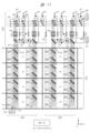
図4は、実施の形態1の2次元アレイ超音波探触子2の回路構成等を示し、連続波ドプラモード(Cモード)時の回路状態例を示す。図4では、連続波ドプラにおける受信信号の位相弁別の例を示す。図4のような回路は、探触子2内のICに実装される。探触子2は、大別して、アレイ部分220と外側部分230とを有する。探触子2のアレイ部分220では、複数(M)の振動子チャネル201における受信回路101、複数の第1マルチプレクサ102、および複数の第1配線103等が2次元アレイ状に実装されている。アレイ部分220の外側部分230では、第2配線104、複数のスイッチ105、複数の第2マルチプレクサ108、複数の第1出力ポート107、および複数の第2出力ポート106が実装されている。
[1-4. C mode]
FIG. 4 shows the circuit configuration of the two-dimensional array
本例では、図面での縦方向、振動子3の列に対応する方向が第1方向(Y方向)であり、図面での横方向、振動子3の行に対応する方向が第2方向(X方向)である。なお、相対的な関係であるため、行と列を取り換えた場合でも、本発明は同様に成立する。図4では、探触子2のアレイ全体のうち一部を簡略化して図示している。多数(M個)の振動子チャネル201があるが、図4では8×4個の部分のみ図示している。アレイのY方向での行数をm1、X方向での列数をm2とすると、m1×m2=Mである。
In this example, the vertical direction in the drawing, the direction corresponding to the columns of
振動子3毎の振動子チャネル201の受信回路101は、第1マルチプレクサ102を介して、第1配線103の複数の信号線に接続されている。振動子3毎に配置された第1マルチプレクサ102には、第1レジスタ109が接続されている。受信回路101は、第1マルチプレクサ102での切り替え・選択状態に応じて、第1配線103のいずれかの信号線に接続される。第1マルチプレクサ102は、1つの振動子3と第1配線103の複数の信号線とを接続して出力先の信号線を切り替え可能である1:n接続のマルチプレクサであり、本例ではn=4である。各第1マルチプレクサ102は、制御論理回路9から第1レジスタ109に設定された制御用の情報によって、切り替え・選択状態が制御される。なお、1:nの意味は、入力が1、出力が複数(n)という意味である。
The receiving
第1配線103は、振動子3列毎に第1方向に延在するように配置された複数の信号線である。X方向では複数の第1配線103を有する。1つの振動子3列の第1配線103は、Cモードでの連続波ドプラ受信信号の位相数以上の本数の信号線である。本例では、この第1配線103は、4位相分に対応した4本の信号線である。第1配線103の4本の信号線は、連続波ドプラ受信信号の位相弁別における4位相のいずれかの位相に対応付けられる。位相弁別単位であるグループの例を、グループG1~G4として示す。あるグループは、ある位相と対応付けられる。例えば、第1グループG1の受信回路101は、第1マルチプレクサ102を介して、第1配線103のうちの左側の第1信号線に接続されている。第2グループG2の受信回路101は、第1マルチプレクサ102を介して、第1配線103のうちの左から2番目の第2信号線に接続されている。
The
複数の列に対応する複数の第1配線103同士は、外側部分230で、第2配線104に接続されている。第2配線104は、第2方向(X方向)に1行として延在するように配置された複数の信号線である。第2配線104は、第1配線103の複数(4本)の信号線の本数に対応した複数(4本)の信号線を有する。第1配線103および第2配線104における複数の信号線は、連続波ドプラ受信信号の複数の位相と対応付けられている。例えば、第1配線103の左側の第1信号線は、第2配線104の上側の第1信号線と接続されており、第1位相と対応付けられる。第1配線103の第2信号線は、第2配線104の上から2番目の第2信号線と接続されており、第2位相と対応付けられる。
The
第2配線104上では、複数の列の第1配線103が、複数のスイッチ105の介在によって、複数の部分に分けられている。本例では、スイッチ105間で、2列の第1配線103の部分毎に分けられている。スイッチ105は、Bモード時(図5)に、複数の振動子チャネル201(対応する複数の第1配線103)の複数の受信信号を、整相加算単位であるサブアレイ200毎に電気的に分離・切断するためのスイッチである。Bモード時には、制御論理回路9からの切り替えの制御に基づいて、すべてのスイッチ105がオフ状態とされる。これにより、複数の第1配線103は、整相加算単位であるサブアレイ200のグループ毎に分離される。Cモード時には、図示のように、制御論理回路9からの切り替えの制御に基づいて、すべてのスイッチ105がオン状態とされる。これにより、第2配線104の4本の信号線は、X方向でアレイの端から端まで(図示省略)、電気的に接続された状態となる。そして、第2配線104の信号線毎に、位相弁別単位のグループが接続されている状態となる。
On the
第2配線104には、スイッチ105間の部分毎に、第1配線103および第2配線104の信号線の本数(4個)に対応した複数(4個)の第2出力ポート106が接続されている。第2配線104の複数(4本)の信号線に対し、一対一で複数の複数(4個)の第2出力ポート106が接続されている。これらの第2出力ポート106は、Bモード用であり、Cモードでは使用されない。
A plurality (four) of
第2配線104上では、外側部分230の一部において、複数の第2マルチプレクサ108を介して複数の第1出力ポート107が接続されている。第1出力ポート107は、Cモード時の連続波ドプラ受信信号用の出力ポートである。設ける第1出力ポート107の数は、少なくとも位相弁別の位相数(例えば4)に対応した数であり、それ以上の数としてもよい。第1出力ポート107毎に配置された第2マルチプレクサ108には、第2レジスタ110が接続されている。各第1出力ポート107は、第2配線104の4位相の4本の信号線のうち、制御論理回路9からの制御に基づいた、第2マルチプレクサ108での切り替え・選択状態に応じて、所望の位相の信号を選択して出力できる。第2マルチプレクサ108は、第2配線104の複数の信号線と第1出力ポート107とを接続して出力元の信号線を切り替え可能である、n:1接続のマルチプレクサであり、本例ではn=4である。各第2マルチプレクサ108は、制御論理回路9からレジスタ110に設定された制御用の情報によって、切り替え・選択状態が制御され、第2配線104のいずれかの信号線が出力元として接続される。
On the
本体装置5の制御装置8からの制御に基づいて、制御論理回路9からは、第1レジスタ109および第2レジスタ110に、対応するマルチプレクサの制御用の情報が設定・格納される。
Based on control from the
上記のように、探触子2は、振動子3毎に配置された第1マルチプレクサ102と、Cモード用の第1出力ポート107毎に配置された第2マルチプレクサ108との組合せによる階層的なスイッチによる回路構成を有する。なお、マルチプレクサは、広義にはスイッチである。このような回路構成によって、2種類のモードの受信動作として、Bモードでの整相加算と、Cモードでの位相弁別との両方に対応できる。このような回路構成によって、探触子2は、先行技術例よりも少数のスイッチおよび配線で、2種類のモードに対応でき、回路規模および消費電力を低減できる。
As described above, the
Cモードでは、ビームフォーミングが可能である。Cモードの受信動作時、本体装置5の制御装置8からの制御に基づいて、制御論理回路9に、連続波ドプラ受信のフォーカス点(例えば心臓の弁の逆流位置)が設定される。その設定に応じて、探触子2の各振動子チャネル201は、上記4位相のうちのどの位相に割り当てられるかが設定される。その設定に対応して、制御論理回路9から第1レジスタ109に選択位相情報が格納される。選択位相情報は、第1マルチプレクサ102が第1配線103のどの信号線を選択して出力先とするかを表す制御用の情報である。第1配線103および第2配線104の信号線毎に、対応する位相が割り当てられる。各第1マルチプレクサ102は、第1レジスタ109の選択位相情報に従って、対応する受信回路101を、第1配線103のうちの選択された信号線に接続する。
In C mode, beamforming is possible. During the receiving operation in C mode, the focus point of the continuous wave Doppler reception (for example, the regurgitation position of a heart valve) is set in the
また、Cモードの受信動作時、本体装置5の制御装置8からの制御に基づいて、制御論理回路9に、Cモード用の第1出力ポート107あたりに接続される振動子3(対応する振動子チャネル201)の数が均等になるように、各第1出力ポート107の選択位相を割り当てる設定が行われる。この設定に応じて、制御論理回路9から、第2レジスタ110に、各第1出力ポート107の選択位相を割り当てる制御用の情報が格納される。この選択位相割り当て情報は、第2マルチプレクサ108が第2配線104のどの位相の信号線を選択して出力するかを表す情報である。第2マルチプレクサ108は、この選択位相割り当て情報に従って、第2配線104のうちの選択された位相の信号線に接続する。これに対応して、各第1出力ポート107は、選択された位相の受信信号を出力する。
During the reception operation in C mode, based on the control from the
上記設定に基づいて、複数の振動子チャネル201は、図示の例のように、位相弁別の複数のグループG1~G4に分類され、グループ毎の位相の受信信号が、対応する第1出力ポート107毎に出力される。
Based on the above settings, the
第1出力ポート107あたりに接続される振動子チャネル数の均等とは、なるべく同じ数または近い数にすることで偏り・不均等を避けることである。例えば、左側の1つの第1出力ポート107は、第2配線104の第1信号線に接続されている位相弁別の第1グループG1の受信信号を出力する。左から2番目の第1出力ポート107は、第2配線104の第2信号線に接続されている位相弁別の第2グループG2の受信信号を出力する。均等とは、これらの各第1出力ポート107間において各グループとして加算等される信号の数をなるべく同じにすることである。
The equal number of transducer channels connected per
なお、図4では、振動子チャネルの一部のみを図示しているので、グループ毎に属する振動子チャネル数が異なってみえているが、実際にはより多くの振動子チャネルがあり、第1出力ポート107あたりに接続されるグループ毎の振動子チャネル数を均等にすることができる。例として、第1出力ポート107の総数が100個であり、グループG1~G4のそれぞれの受信信号の数がg1~g4であるとする。図4の例で見えている8×4の振動子チャネル部分のみ考えた場合、グループの受信信号数の比(g1:g2:g3:g4)は、1:13:15:3である。第1出力ポート107の総数100を、この比に対応させて配分すればよい。これにより、グループ毎に割り当てる第1出力ポート107の数の比は、例えば、4:40:46:10といったようにすることができる。例えば第1グループG1の1個の受信信号は、4個の第1出力ポート107が使用され、第2グループG2の13個の受信信号は、40個の第1出力ポート107が使用される。1つの第1出力ポート107あたりでは、どれも約4個の振動子チャネルの受信信号が1つにまとめられることとなる。
In FIG. 4, since only a portion of the transducer channels is illustrated, the number of transducer channels belonging to each group appears to be different, but in reality there are many more transducer channels, and the number of transducer channels for each group connected to each
このように、第1出力ポート107あたりに接続される振動子チャネル数の均等化によって、Cモード時に本体装置5で受信信号に基づいて得られる画像において、フォーカス点への依存(対応する不均等)による明るさの無用なばらつきが少ない好適な連続波ドプラ画像を得ることができる。
In this way, by equalizing the number of transducer channels connected per
図4の例のように、Cモードの受信動作時、アレイ部分220の複数の振動子チャネル201における複数の連続波ドプラ受信信号は、位相弁別として4位相に対応させた4つのグループG1~G4に弁別される。そして、位相のグループの受信信号毎に分けて、異なる第1出力ポート107から出力される。図示の一例では、アレイ面において、4つのグループG1~G4は、階段状に分かれている。この例は、フレネルリング状の位相分布に対応している。位相弁別は4つの位相に限らずに可能である。
As shown in the example of FIG. 4, during a C-mode receiving operation, multiple continuous wave Doppler receiving signals in
Cモード時に、複数の第1出力ポート107(図2での複数の出力ポート6と対応する)から出力された複数の受信信号は、ケーブル4を通じて、本体装置5の複数の入力ポート7へ伝送され、それぞれの受信回路70で処理される。本体装置5の受信回路70は、それらの複数の受信信号に基づいて、位相調整された連続波周波数信号とのミキシングによってベースバンドに復調し、復調した複数の受信信号を加算してより少数の受信信号にする。このような動作によって、本体装置5内で整相加算が行われる。この動作は、図3での微小遅延回路36による遅延、加算と対応している。
In mode C, the multiple received signals output from the multiple first output ports 107 (corresponding to the
上記のように、実施の形態1の探触子2の回路構成では、探触子2内の回路で振動子3毎に受信信号に遅延による整相加算を行う必要が無いので、そのための増幅回路や遅延回路等のアクティブ回路の使用または実装が不要である。探触子2内の回路では、本体装置5側での復調および整相加算のための前処理として上記位相弁別を行えばよい。上記位相弁別は、上記マルチプレクサ等による階層的なスイッチ構成で実現でき、パッシブ回路のみで実現できる。これにより、Cモードの受信動作時、探触子2のICの消費電力を低減できる。
As described above, in the circuit configuration of the
[1-5.Bモード]
図5は、前の図4と同じ探触子2の回路構成において、Bモード時の回路状態例を示す。図5では、Bモード時の受信信号の整相加算の例を示す。Bモードの受信動作時に、複数の第1配線103は、整相加算単位として複数のサブアレイ200に分けられる。本例では、縦横で2×2=4個の振動子チャネル201を1つのサブアレイ200としている。縦横で例えば8×2個の振動子チャネル201は、Y方向に4個のサブアレイ200(例えばA1~A4)に分けられ、第2配線104のスイッチ105間の部分に接続されている。同様に、そのようなY方向の4個のサブアレイ200が、X方向に複数構成されている。
[1-5. B mode]
FIG. 5 shows an example of the circuit state in B mode in the circuit configuration of the
それぞれのサブアレイ200では、複数(4個)の振動子チャネル201の受信回路101が、各第1マルチプレクサ102の選択状態に応じて、第1配線103の複数(4本)の信号線のうちの、サブアレイ200毎に別の信号線に接続されている。これにより、各サブアレイ200として分離されている。例えば、サブアレイA1では、4個の振動子チャネル201の受信回路101は、第1マルチプレクサ102での選択状態を介して、すべて、第1配線103のうちの左側の第1信号線に接続されている。サブアレイA2では、4個の受信回路101は、すべて、第1配線103のうちの左から2番目の第2信号線に接続されている。
In each
Bモードの受信動作時には、スイッチ105がオフ状態にされ、第2出力ポート106が使用される。第1出力ポート107はスイッチ105を介して分離されているので使用されない。スイッチ105のオフ状態によって、第2配線104の4本の信号線は、一対一でBモード用の第2出力ポート106に接続されている。
During reception in B mode,
1つのサブアレイ200(例えばサブアレイA1)の4個の受信信号は、第1配線103の対応する信号線を通じて、第2配線104上のスイッチ105間の部分で同じ1つの信号線(例えば上側の第1信号線)に接続され、その信号線に接続されている第2出力ポート106から出力される。すなわち、1つのサブアレイ200の4個の受信信号は、そのような配線を通じて整相加算された1つの受信信号となって、第2出力ポート106から出力される。同様に、Y方向で4個のサブアレイ200をみると、サブアレイ200毎の受信信号が、第1配線103および第2の配線104の別々の信号線を通じて分離された状態で、それぞれに対応する別々の第2出力ポート106から出力される。スイッチ105間の部分に接続される、X方向で隣り合う2列をみると、4個の第2出力ポート106から、4個のサブアレイ200(例えばA1~A4)の受信信号が分離された状態で出力される。
The four received signals of one subarray 200 (e.g., subarray A1) are connected to the same signal line (e.g., the upper first signal line) in the portion between the
図5の回路状態で、4個の振動子チャネル201による1つのサブアレイ200において、整相加算として以下が行われる。Bモード時のパルス受信信号には、受信回路101(図3での微小遅延回路36)で遅延がかけられる。この遅延による整相では、サブアレイ200の4個の振動子チャネル201間で、受信信号の位相がコヒーレントに揃えられる。その後、それらの4個の受信信号が、上記第1マルチプレクサ102、第1配線103、および第2配線104を通じて1つの受信信号として加算される。このようにして、サブアレイ200毎に整相加算された後の受信信号が、第2出力ポート106から出力される。
In the circuit state of FIG. 5, the following phasing addition is performed in one
また、図5のBモード時に、第1レジスタ109に格納される制御用の情報は、前述のCモード時の選択位相情報ではなく、各振動子チャネル201がどの整相加算単位であるサブアレイ200に属するかを表す情報である。そのため、サブアレイ200の構成が固定的である場合には、第1レジスタ109の制御用の情報は、ビームフォーミングのフォーカス位置に依らずに、振動子3毎に決まる情報である。よって、この場合のこの制御用の情報は、制御装置8および制御論理回路9が、予め決めて固定的に設定しておけばよく、都度に計算して設定する必要は無い。また、サブアレイ200の構成を都度に変更できる構成も可能である。この場合、第1レジスタ109に格納される制御用の情報は、制御装置8および制御論理回路9が、都度に計算して設定すればよい。例えば、図示のY方向で隣り合う2つのサブアレイ200を、同じ信号線に接続されるように制御することで、1つのサブアレイにまとめることができる。
In addition, in the B mode of FIG. 5, the control information stored in the
[効果等]
上記のように、実施の形態1の2次元アレイ超音波探触子によれば、連続波ドプラモード(Cモード)とそれ以外の撮像モード(Bモード)等のモードとの少なくとも2種類のモードでの受信動作が可能である高度な機能を備える装置を実現でき、かつ、回路規模および消費電力を低減できる。実施の形態1によれば、2次元アレイ超音波探触子の回路において、先行技術例(例えば特許文献1のマトリックススイッチ)よりも、少数のスイッチや配線等での回路構成が実現できる。また、この回路構成では、アレイの振動子チャネル201と本体装置5のチャネルとの間では、主にスイッチやマルチプレクサのようなパッシブ回路のみを介して接続でき、増幅器や遅延回路等のアクティブ回路の使用を最小限にできる。これにより、この回路構成では、Cモード時に、低消費電力で低雑音での受信動作を実現できる。さらに、この回路構成では、Cモード時に、アレイの出力ポート毎に接続される振動子チャネル数を均等にすることができる。これにより、ビームフォーミングを行う場合のフォーカス点への依存による明るさの無用なばらつきが少ない好適な連続波ドプラ画像を得ることができる。
[Effects, etc.]
As described above, according to the two-dimensional array ultrasonic probe of the first embodiment, a device having advanced functions capable of receiving in at least two modes, such as a continuous wave Doppler mode (C mode) and another imaging mode (B mode), can be realized, and the circuit size and power consumption can be reduced. According to the first embodiment, in the circuit of the two-dimensional array ultrasonic probe, a circuit configuration can be realized with fewer switches, wiring, etc. than the prior art example (for example, the matrix switch of Patent Document 1). Furthermore, in this circuit configuration, the
<実施の形態2>
図6~図7を用いて、本発明の実施の形態2の2次元アレイ超音波探触子について説明する。実施の形態2等の基本構成は実施の形態1と同様であり、以下では、実施の形態2等における実施の形態1とは異なる構成部分について主に説明する。実施の形態2は、実施の形態1に対し、探触子2の回路構成の変形例に相当する。いずれの形態も、先行技術例に比べて回路規模および消費電力を低減できる効果は共通である。
<
A two-dimensional array ultrasonic probe according to a second embodiment of the present invention will be described with reference to Figures 6 and 7. The basic configuration of the second embodiment is the same as that of the first embodiment, and the following mainly describes the components of the second embodiment that are different from the first embodiment. The second embodiment corresponds to a modification of the circuit configuration of the
前述(図4等)の実施の形態1では、Cモード用の第1出力ポート107と、Bモード用の第2出力ポート106とが別に設けられていた。一方、実施の形態2では、探触子2の出力ポートとして、第1出力ポート107と第2出力ポート106との区別が無く、各モードで共通に使用できる出力ポートを有し、Cモードか否かに係わらず同じ出力ポートを使用できる。これにより、実施の形態2では、探触子2に備える出力ポート数をより少数に低減でき、対応してケーブル4の数も低減できる。
In the above-mentioned embodiment 1 (FIG. 4, etc.), the
[2-1.Cモード]
図6は、実施の形態2での探触子2の回路構成におけるCモード時の回路状態例として、位相弁別の例を示す。実施の形態2の探触子2で、アレイ部分220において、各振動子チャネル201の受信回路101が第1マルチプレクサ102を介して第1配線103に接続される構成、および外側部分230において第2配線104に接続される構成は、実施の形態1と同様である。第1マルチプレクサ102に接続される第1レジスタ109には、制御用の情報として、選択位相情報が格納される。
[2-1. C mode]
6 shows an example of phase discrimination as an example of the circuit state in C mode in the circuit configuration of the
Cモード時、外側部分230において、第2配線104は、複数のスイッチ105がオン状態に接続されることで、アレイの端から端までが電気的に接続されている。外側部分230において、第2配線104に対し、スイッチ105間の部分毎に、複数のマルチプレクサ207を通じて複数の出力ポート206が設けられている。この出力ポート206は、言い換えると、2種類のモードで共通使用される共用出力ポートである。出力ポート206毎に、マルチプレクサ207が配置されている。このマルチプレクサ207は、第2配線104の複数(4本)の信号線と出力ポート206とを接続する、n:1接続のマルチプレクサであり、n=4である。各マルチプレクサ207には制御用のレジスタ209が接続されている。Cモード時、各レジスタ209には、出力ポート206の選択位相割り当て情報が格納される。
In mode C, in the
図6の例では、アレイ部分220におけるX方向での2列が、第2配線104のスイッチ105間の部分に接続されている。この部分において、第2配線104の4本の信号線に対し、4個のマルチプレクサ207を介して4個の出力ポート206が接続されている。
In the example of FIG. 6, two columns in the X direction in the
図6の例では、前述(図4)と同様に、位相弁別の例として、4位相に対応する4個のグループG1~G4に分ける例を示している。例えば、グループG1の振動子チャネル201の受信信号は、第1配線103の第1信号線、第2配線104の第1信号線、およびそれぞれのスイッチ105間の部分における4個のマルチプレクサ207のうちの左側のマルチプレクサ207を通じて、それぞれの部分毎に1つの受信信号として、4個の出力ポート206のうちの例えば左側の出力ポート206(p11)から出力される。同様に、グループG2の振動子チャネル201の受信信号は、第1配線103の第2信号線、第2配線104の第2信号線、およびスイッチ105間の部分における4個のマルチプレクサ207のうちの左から2番目のマルチプレクサ207を通じて、それぞれの部分毎に1つの受信信号として、4個の出力ポート206のうちの例えばいくつかの出力ポート206(p12,p13,p14)から出力される。
In the example of Figure 6, as in the above (Figure 4), an example of phase discrimination is shown in which the signal is divided into four groups G1 to G4 corresponding to four phases. For example, the received signal of the
また、実施の形態2でも、実施の形態1と同様に、ビームフォーミングを伴うCモードの受信動作の際に、出力ポート206あたりに接続される振動子チャネルの数の均等化が行われる。
Also, in the second embodiment, as in the first embodiment, the number of transducer channels connected per
[2-2.Bモード]
図7は、実施の形態2での探触子2の回路構成における、Bモード時の回路状態例として、サブアレイ200等の例を示す。Bモードでは、外側部分230における第2配線104は、整相加算単位毎に分離する必要があるため、すべてのスイッチ105はオフ状態に接続される。整相加算単位であるサブアレイ200は、実施の形態1の例(図5)と同様であり、縦横での2×2=4個の振動子チャネル201の集まりである。
[2-2. B mode]
7 shows an example of a
Bモード時、出力ポート206毎のマルチプレクサ207は、レジスタ209の情報に応じて、第2配線104のうちどの信号線を出力元として出力ポート206に出力するかを選択する。レジスタ209に格納される情報は、サブアレイ200に対応させて、第2配線104のどの信号線を選択するかを表す情報である。実施の形態2では、このように第1マルチプレクサ102とマルチプレクサ207との組合せによる階層的なスイッチ構成に基づいて、複数の振動子チャネル201の複数の受信信号をどのサブアレイ200に分けてどの出力ポート206から出力するかが決められる。2列毎に対応するスイッチ105間の部分において、制御に応じて、サブアレイ200毎の受信信号の加算出力が、4個の出力ポート206のうちの対応する出力ポート206から出力される。
In mode B, the
[効果等]
上記のように、実施の形態2の2次元アレイ超音波探触子によれば、実施の形態1と同様の効果の他に、探触子2に備える出力ポート数をより少数に低減でき、対応してケーブル4の数も低減できる。
[Effects, etc.]
As described above, according to the two-dimensional array ultrasonic probe of
<実施の形態3>
図8~図9を用いて、本発明の実施の形態3の2次元アレイ超音波探触子について説明する。実施の形態3は、実施の形態2の変形例である。図8等に示す実施の形態3の探触子2における回路構成では、実施の形態2と同様に共用出力ポートである出力ポート307を備え、また、前述の第2配線104に関して、CモードとBモードとで、使用する配線を一部分離する。これにより、連続波ドプラ受信信号のパスの直列抵抗を低減する。
<Third embodiment>
A two-dimensional array ultrasonic probe according to a third embodiment of the present invention will be described with reference to Figures 8 and 9. The third embodiment is a modified example of the second embodiment. The circuit configuration of the
前述の実施の形態1,2では、アレイの外側部分230における第2配線104には、整相加算単位の分離のための複数のスイッチ105が挿入されていた。このような回路構成の場合、スイッチ105のオン抵抗による、信号振幅減少、ばらつき、熱雑音増加への影響が懸念される。特に、Cモード時に、振動子3からの受信信号を、前述の増幅器等を使用せずにパッシブ回路のみを介して出力する場合、前述の利点があるが、探触子2内では増幅器による信号増幅やインピーダンス変換ができない。そのため、この場合、スイッチ105のオン抵抗の影響が強く表れる懸念がある。例えば、アレイ部分220においてX方向で左端に位置する振動子3と、外側部分230においてX方向で右端に位置する出力ポートとを電気的に接続する場合、2次元アレイが大規模になるほど、その接続の経路上に介在するスイッチ105の直列数も増える。これに応じて、第2配線104上で高い抵抗が付いてしまう。
In the above-mentioned first and second embodiments, a plurality of
そこで、実施の形態3の探触子2における回路構成では、外側部分230における前述の第2配線104について、図8等のように、Bモード用の配線304と、Cモード用の配線305とに分離された回路構成を有する。アレイ部分220の複数の第1配線103に対し、X方向に延在するBモード用の配線304が接続されている。Bモード用の配線304は、第1配線103の複数の信号線の本数に対応して一対一で接続される複数の信号線を有する。Bモード用の配線304は、X方向でサブアレイ200の構成に対応させて分離された複数の配線として設けられている。この配線は例えば2列毎の配線である。また、実施の形態3では、アレイ部分220の複数の第1配線103に対し、スイッチ306を介して、X方向に延在するCモード用の配線305が接続されている。
Therefore, in the circuit configuration of the
[3-1.Cモード]
図8は、実施の形態3での探触子2の回路構成における、Cモード時の回路状態例として、位相弁別の例を示す。この探触子2は、アレイ部分220の外側部分230において、Cモード用の配線305と、Bモード用の配線304と、スイッチ306と、スイッチ309とが配置されている。第1配線103は、外側部分230で、Bモード用の配線304に接続され、また、スイッチ306を介して、Cモード用の配線305に接続されている。図示しないが、各スイッチは、制御論理回路9からの制御信号に応じて切り替えが制御される。
[3-1. C mode]
8 shows an example of phase discrimination as an example of the circuit state in C mode in the circuit configuration of the
スイッチ306は、振動子3の列毎に設けられたスイッチであり、第1配線103毎に複数(4本)の信号線に一対一で設けられた複数(4個)のスイッチで構成されている。Cモード時には、Cモード用の配線305を使用するため、スイッチ306がオン状態に制御される。Cモード時、Bモード用の配線304と出力ポート307とを接続するスイッチ309はオフ状態に制御される。
The
Cモード用の配線305には、実施の形態2と同様に、複数のマルチプレクサ308を介して複数の出力ポート307が配置されている。出力ポート307は、実施の形態2と同様に、各モードで共有利用される共用出力ポートである。出力ポート307毎のマルチプレクサ308は、レジスタ309に設定される制御用の情報に基づいて、Cモード用の配線305の複数の信号線のうちのいずれかの信号線を出力元として選択して出力ポート307に出力する。また、各出力ポート307には、マルチプレクサ308を介さずに、Bモード用の配線304の対応する1つの信号線から1つのスイッチ309を介して信号線が接続されている。スイッチ309は、Bモード用の配線304における2列毎の配線毎に、複数の信号線に対し一対一で接続される複数(4個)のスイッチとして設けられている。
In the
Cモードの受信動作時、例えばグループG1の振動子チャネル201の受信信号は、第1配線103の第1信号線から、オン状態のスイッチ306を通じて、Cモード用の配線305の第1信号線に伝送される。そして、その第1信号線の受信信号は、位相弁別に応じたマルチプレクサ308の選択状態に応じて、選択された出力ポート307(例えばp31)から出力される。同様に、グループG2の複数の受信信号は、第1配線103の第2信号線、スイッチ306、配線305の第2信号線、マルチプレクサ308を介して、選択された出力ポート307(例えばp32,p33,p34)から出力される。実施の形態3でも、実施の形態1,2と同様に、出力ポート307あたりに接続される振動子チャネルの数が均等化される。
During a receiving operation in C mode, for example, a receiving signal of the
[3-2.Bモード]
図9は、実施の形態3での回路構成における撮像モード時の回路状態例として、サブアレイ200の例を示す。Bモードでは、Cモード用の配線305を使用しないので、スイッチ306がオフ状態に制御される。Bモード用の配線304に接続されるスイッチ309はオン状態に制御される。出力ポート307毎のマルチプレクサ308もすべてオフ状態に制御される。
[3-2. B mode]
9 shows an example of the
このBモードの状態では、サブアレイ200の制御に基づいて、振動子3毎の受信信号は、第1配線103、Bモード用の配線304、およびスイッチ309を経由して、サブアレイ200毎に整相加算された受信信号として、選択された出力ポート307から出力される。例えば、サブアレイA1の4個の振動子チャネル201の4個の受信信号は、第1配線103の第1信号線、Bモード用の配線304の第1信号線、およびスイッチ309を経由して、整相加算された受信信号として、選択された出力ポート307(p31)から出力される。
In this B mode state, based on the control of the
[効果等]
上記のように、実施の形態3の2次元アレイ超音波探触子によれば、実施の形態1,2と同様の効果に加え、以下の効果を有する。実施の形態3では、Cモード用の配線305上に、前述(図6等)の第2配線104に挿入されている複数のスイッチ105は無い。実施の形態3の探触子2における回路構成では、振動子3から出力ポート307までの受信信号のパスにおいて、スイッチ306によるオン抵抗は付いてしまうものの、複数のスイッチ105が直列接続された状態にはならない。これにより、この回路構成では、Cモードにおける受信信号のパスの直列抵抗を低くすることができる。したがって、実施の形態3によれば、受信信号の出力に関して、前述の信号振幅減少、ばらつき、熱雑音増加等への影響の懸念を解消できる。
[Effects, etc.]
As described above, the two-dimensional array ultrasonic probe of the third embodiment has the following effects in addition to the effects of the first and second embodiments. In the third embodiment, the
<実施の形態4>
図10~図11を用いて、本発明の実施の形態4の2次元アレイ超音波探触子について説明する。実施の形態4は、実施の形態3の変形例である。実施の形態4では、余る配線を活用して、連続波ドプラ受信時の配線抵抗を実効的に下げる回路構成を示す。前述の実施の形態1~3では、Cモード時の連続波ドプラ受信信号の位相の数(位相数Iとする)と、探触子2の2次元アレイの振動子3列毎の第1配線103の信号線の本数(配線数Jとする)との関係において、位相数Iと配線数Jとが同じである場合(I=J)を想定していた。また、Bモードでは、第1方向において整相加算単位であるサブアレイ200が並ぶ数(単位数Kとする)が4である場合を想定していた。そのため、配線数Jは4でよかった。これらの数(I,J,K)は、勿論、前述の例に限定されない。実際の実装では、Cモードでの位相数Iと、Bモードでの単位数Kとが異なっていてもよい。それらが異なる場合には、それらのうち大きい方の数に合わせて配線数Jを決めればよい。
<Fourth embodiment>
A two-dimensional array ultrasonic probe according to a fourth embodiment of the present invention will be described with reference to FIGS. 10 to 11. The fourth embodiment is a modified example of the third embodiment. In the fourth embodiment, a circuit configuration is shown that effectively reduces the wiring resistance during continuous wave Doppler reception by utilizing surplus wiring. In the first to third embodiments described above, in the relationship between the number of phases (defined as the number of phases I) of the continuous wave Doppler reception signal in the C mode and the number of signal lines (defined as the number of wirings J) of the
実施の形態4では、Cモードでの受信信号の位相数Iの方が、Bモードでの第1方向に並ぶ整相加算単位の単位数Kよりも少ない場合(I<K)を想定する。例えば、位相数Xが3であり、縦横の2×2=4個の振動子チャネル201によるサブアレイ200を整相加算単位として単位数Kが4である場合を説明する。配線数Jは、多い方である単位数Kに合わせて4とする。
In the fourth embodiment, it is assumed that the number of phases I of the received signal in C mode is less than the number of units K of the phase-matching and summing units arranged in the first direction in B mode (I<K). For example, a case will be described in which the number of phases X is 3, and the number of units K is 4, with the
位相数Iの方が単位数Kおよび配線数Jよりも大きい関係である場合、Bモードにおいて、配線の信号線が余ることになる。また、実施の形態4のように、Bモードでの単位数Kの方が位相数Iよりも大きい関係である場合(I<K)、Cモードにおいて、配線の信号線が余ることになる。例えば、前述の第1配線103の4本の信号線(左側から順に第1信号線~第4信号線)のうち、3本の信号線が、連続波ドプラの3位相の位相弁別の出力に使用される場合に、残りの1本の信号線が余る。そこで、実施の形態4では、実施の形態3での回路構成に対し、さらに、Cモードにおいて余る配線を用いて、配線抵抗を実効的に下げることができる機構が追加されている。
When the number of phases I is greater than the number of units K and the number of wires J, there will be surplus signal lines in the wiring in B mode. Also, as in the fourth embodiment, when the number of units K in B mode is greater than the number of phases I (I<K), there will be surplus signal lines in the wiring in C mode. For example, when three of the four signal lines (first signal line to fourth signal line from the left) of the
[4-1.Cモード]
図10は、実施の形態4での探触子2の回路構成におけるCモード時の回路状態例として、位相弁別の例を示す。図10および図11の探触子2の回路構成では、実施の形態3での回路構成に対し、アレイの外側部分230において、マルチプレクサ412およびレジスタ413が追加されている。また、Cモード用の配線405は、4本ではなく位相数に対応した3本の信号線を有する。出力ポート307毎のマルチプレクサ408は、n:1接続として、4:1接続ではなく、3:1接続のマルチプレクサである。スイッチ406は、第1配線103のうちの3本の信号線に接続される3個のスイッチで構成されている。Bモード用の配線304は、前述と同様に4本の信号線を有し、そのうちの1本である第4信号線には、マルチプレクサ412が接続されている。マルチプレクサ412は、1:n接続として1:3接続のマルチプレクサである。マルチプレクサ412の3本の出力は、Cモード用の配線405の3本の信号線に接続されている。各マルチプレクサ408は、3本の入力が、配線405の3本の信号線に一対一で接続されている。
[4-1. C mode]
FIG. 10 shows an example of phase discrimination as an example of the circuit state in the C mode in the circuit configuration of the
第1配線103の4本の信号線のうち、例えば左から3本の信号線(第1信号線~第3信号線)は、3位相の位相弁別に使用される。第1配線103の4本の信号線のうち、右側の1本の信号線(第4信号線)は、余り配線103dである。余り配線103dは、Bモード用の配線304に接続されており、Cモード用の配線405には接続されていない。言い換えると、Bモード用の配線304の第4信号線である信号線304dは、余り配線103dの延長上の信号線である。
Of the four signal lines of the
マルチプレクサ412は、余り配線103dの延長上の信号線304dと、Cモード用の配線405の位相数分の3本の信号線との間を接続するように配置されている、1:3接続のマルチプレクサである。レジスタ413には、制御論理回路9からマルチプレクサ412の制御用の情報が格納される。レジスタ413に格納される制御用の情報は、マルチプレクサ412の出力配線選択を表す情報である。すなわち、この回路構成では、第1マルチプレクサ102およびマルチプレクサ412の選択状態に応じて、余り配線103dは、Cモード用の配線405の3位相の3本の信号線のうちのいずれにも接続可能である。余り配線103dに接続される振動子チャネル201の受信信号は、Cモード用の配線405のうちの選択された信号線に出力され、マルチプレクサ408でのその信号線の選択に応じて、出力ポート307から出力される。
The
Cモードの受信動作時、第1配線103のうち3本の信号線(第1信号線~第3信号線)は、オン状態のスイッチ406を介して、Cモード用の配線405に接続される。これらの3本の信号線は、連続波ドプラの位相弁別の3位相(第1位相、第2位相、第3位相とする)に割り当てられる。図10の位相弁別の例では、8×4の振動子チャネル201の部分において、位相弁別の3個のグループG1~G3を示す。例えばグループG1は、第1位相のグループであり、第1マルチプレクサ102は、第1信号線を出力先として選択する状態とされている。
During a C-mode reception operation, three signal lines (first to third signal lines) of the
ここで、同一の配線である第1配線103に、多数の振動子3(対応する振動子チャネル201)が接続される場合、その配線を流れる電流が増加し、配線抵抗の影響が大きく表れる懸念がある。そこで、実施の形態4では、第1配線103のうちの余り配線103dを活用することで、同一の配線に接続される振動子チャネル数を減少させ、配線抵抗の影響を低減する。
Here, if a large number of transducers 3 (corresponding transducer channels 201) are connected to the same
実施の形態4の探触子2では、同じ位相に弁別される振動子チャネル201がY方向に多く存在する場合に、余り配線103dおよび第1マルチプレクサ102を利用して、振動子チャネル201が接続される信号線を分散する。例えば図10では、ある2列の振動子3の部分X12では、余り配線103dを、3位相のうち、振動子チャネル数が多い位相以外のある位相(例えば第2位相)に割り当てる。別の2列の振動子3の部分X34では、余り配線103dを、3位相のうち、振動子チャネル数が多い位相以外の別のある位相(例えば第3位相)に割り当てる、といったように制御される。余り配線103dに接続される振動子チャネル201の箇所を丸印で示す。部分X12におけるマルチプレクサ412は、出力先として第2位相に対応する第2信号線が選択されている。部分X34におけるマルチプレクサ412は、出力先として第3位相に対応する第3信号線が選択されている。このような制御により、Y方向の同じ配線の1本の信号線あたりに接続される振動子チャネル数を低減でき、実効的な配線抵抗の低減ができる。
In the
本体装置5の制御装置8は、振動子3毎の第1マルチプレクサ102のレジスタ109、および出力ポート307毎のマルチプレクサ408のレジスタ309に設定する制御用の情報を、ビームフォーミングのフォーカス情報、および出力ポート307あたりの接続振動子チャネル数の均等化に基づいて計算する。その際、制御装置8は、各々の第1配線103の余り配線103dへの位相の割り当ても決定し、その位相割り当て情報を、対応する第1マルチプレクサ102のレジスタ109、およびマルチプレクサ412のレジスタ413に転送して設定する。
The
[4-2.Bモード]
図11は、実施の形態4での探触子2の回路構成におけるBモード時の回路状態例として、サブアレイ200の例を示す。Bモードでは、マルチプレクサ412は、オフ状態に制御され、使用されない。よって、この状態では、図11の回路は、図9の回路の状態と等価となる。余り配線103dの部分は、図11では、サブアレイA4,A8で使用されている。サブアレイA4,A8の受信信号は、余り配線103d、およびオン状態のスイッチ309を通じて、出力ポート307から出力される。
[4-2. B mode]
Fig. 11 shows an example of the
以上、本発明を実施の形態に基づいて具体的に説明したが、本発明は前述の実施の形態に限定されず、要旨を逸脱しない範囲で種々変更可能である。 The present invention has been specifically described above based on the embodiments, but the present invention is not limited to the above-mentioned embodiments and can be modified in various ways without departing from the gist of the invention.
1…超音波診断装置、2…探触子(2次元アレイ超音波探触子)、3…振動子(超音波振動子)、4…ケーブル、5…本体装置、6…出力ポート、7…入力ポート、8…制御装置、9…制御論理回路、15…表示装置、30…送受信回路、70…受信回路、101…受信回路、102…第1マルチプレクサ、103…第1配線、104…第2配線、105…スイッチ、106…第2出力ポート、107…第2マルチプレクサ、108…第1出力ポート、109…第1レジスタ、110…第2レジスタ、200…サブアレイ、201…振動子チャネル、202…配線、210…IC、220…アレイ部分、230…外側部分、G1~G4…グループ、A1~A8…サブアレイ。 1...ultrasonic diagnostic device, 2...probe (two-dimensional array ultrasonic probe), 3...transducer (ultrasonic transducer), 4...cable, 5...main device, 6...output port, 7...input port, 8...control device, 9...control logic circuit, 15...display device, 30...transmitting/receiving circuit, 70...receiving circuit, 101...receiving circuit, 102...first multiplexer, 103...first wiring, 104...second wiring, 105...switch, 106...second output port, 107...second multiplexer, 108...first output port, 109...first register, 110...second register, 200...subarray, 201...transducer channel, 202...wiring, 210...IC, 220...array portion, 230...outer portion, G1 to G4...group, A1 to A8...subarray.
Claims (14)
連続波ドプラモードである第1モードと、前記連続波ドプラモード以外のモードである第2モードとの少なくとも2種類のモードで超音波受信動作が可能であり、
前記2次元アレイの一方の次元の方向を第1方向とし、他方の次元の方向を第2方向とし、
前記複数の振動子の振動子毎に配置されている受信回路と、
前記受信回路毎に接続されるように配置されている第1マルチプレクサと、
前記第1マルチプレクサと接続されて前記第1方向に延在するように配置されている複数の第1配線と、
前記2次元アレイの外側において、前記複数の第1配線と接続されて前記第2方向に延在するように配置されている第2配線と、
前記第2配線上に配置され、前記複数の振動子の受信信号についての整相加算の単位に対応させて切断可能であるスイッチと、
前記第2配線に接続されている、複数の第2マルチプレクサと、
前記複数の第2マルチプレクサに接続されている、前記第1モードで使用される複数の第1出力ポートと、
前記第2配線上の前記スイッチ間の部分毎に接続されている、前記第2モードで使用される複数の第2出力ポートと、
を備える、超音波探触子。 An ultrasonic probe in which a plurality of transducers are arranged as a two-dimensional array,
The ultrasonic receiving operation is possible in at least two types of modes, a first mode being a continuous wave Doppler mode and a second mode being a mode other than the continuous wave Doppler mode,
A direction of one dimension of the two-dimensional array is a first direction, and a direction of the other dimension is a second direction;
A receiving circuit arranged for each of the transducers of the plurality of transducers;
a first multiplexer arranged to be connected to each of the receiving circuits;
a plurality of first wirings connected to the first multiplexer and arranged to extend in the first direction;
a second wiring connected to the first wirings and arranged to extend in the second direction outside the two-dimensional array;
A switch that is disposed on the second wiring and can be disconnected in correspondence with a unit of delay-and-sum for the reception signals of the plurality of transducers;
a plurality of second multiplexers connected to the second wiring;
a plurality of first output ports used in the first mode, the first output ports being connected to the plurality of second multiplexers;
a plurality of second output ports used in the second mode, the second output ports being connected to each of the portions between the switches on the second wiring;
An ultrasonic probe comprising:
前記2次元アレイの前記複数の振動子の複数の受信信号について、
前記第1モードでは、複数の位相の位相弁別に対応させて複数のグループに分けるように、前記第1マルチプレクサ、前記スイッチ、および前記第2マルチプレクサを制御し、
前記第2モードでは、複数の前記整相加算の単位に分けるように、前記第1マルチプレクサ、前記スイッチ、および前記第2マルチプレクサを制御する、
超音波探触子。 2. The ultrasonic probe according to claim 1,
For a plurality of received signals of the plurality of transducers of the two-dimensional array,
In the first mode, the first multiplexer, the switch, and the second multiplexer are controlled to divide the signals into a plurality of groups corresponding to phase discrimination of a plurality of phases;
In the second mode, the first multiplexer, the switch, and the second multiplexer are controlled so as to divide the signal into a plurality of units of the delay-and-sum operation.
Ultrasound probe.
前記第1マルチプレクサを制御するための第1レジスタを備え、前記第1レジスタに、制御用の情報として、前記第1モードでは前記位相弁別のグループを割り当てるための情報が格納され、前記第2モードでは前記整相加算の単位を割り当てるための情報が格納され、
前記第2マルチプレクサを制御するための第2レジスタを備え、前記第2レジスタに、制御用の情報として、前記第1モードでは前記第1出力ポートが出力する位相を割り当てるための情報が格納される、
超音波探触子。 3. The ultrasonic probe according to claim 2,
a first register for controlling the first multiplexer, wherein information for allocating a group of the phase discrimination in the first mode and information for allocating a unit of the delay-and-sum in the second mode are stored in the first register as control information;
a second register for controlling the second multiplexer, and information for allocating a phase to be output by the first output port in the first mode is stored in the second register as control information;
Ultrasound probe.
前記第1モードでは、前記第1出力ポートあたりに接続される前記振動子の数が均等になるように制御する、
超音波探触子。 2. The ultrasonic probe according to claim 1,
In the first mode, control is performed so that the number of the transducers connected to each of the first output ports is equal.
Ultrasound probe.
連続波ドプラモードである第1モードと、前記連続波ドプラモード以外のモードである第2モードとの少なくとも2種類のモードで超音波受信動作が可能であり、
前記2次元アレイの一方の次元の方向を第1方向とし、他方の次元の方向を第2方向とし、
前記複数の振動子の振動子毎に配置されている受信回路と、
前記受信回路毎に接続されるように配置されている第1マルチプレクサと、
前記第1マルチプレクサと接続されて前記第1方向に延在するように配置されている複数の第1配線と、
前記2次元アレイの外側において、前記複数の第1配線と接続されて前記第2方向に延在するように配置されている第2配線と、
前記第2配線上に配置され、前記複数の振動子の受信信号についての整相加算の単位に対応させて切断可能であるスイッチと、
前記第2配線上の前記スイッチ間の部分毎に接続されている、複数の第2マルチプレクサと、
前記複数の第2マルチプレクサに接続されている、前記第1モードと前記第2モードとで使用される複数の出力ポートと、
を備える、超音波探触子。 An ultrasonic probe in which a plurality of transducers are arranged as a two-dimensional array,
The ultrasonic receiving operation is possible in at least two types of modes, a first mode being a continuous wave Doppler mode and a second mode being a mode other than the continuous wave Doppler mode,
A direction of one dimension of the two-dimensional array is a first direction, and a direction of the other dimension is a second direction;
A receiving circuit arranged for each of the transducers of the plurality of transducers;
a first multiplexer arranged to be connected to each of the receiving circuits;
a plurality of first wirings connected to the first multiplexer and arranged to extend in the first direction;
a second wiring connected to the first wirings and arranged to extend in the second direction outside the two-dimensional array;
A switch that is disposed on the second wiring and can be disconnected in correspondence with a unit of delay-and-sum for the reception signals of the plurality of transducers;
a plurality of second multiplexers connected to each of the portions between the switches on the second wiring;
a plurality of output ports used in the first mode and the second mode, the output ports being connected to the plurality of second multiplexers;
An ultrasonic probe comprising:
前記2次元アレイの前記複数の振動子の複数の受信信号について、
前記第1モードでは、複数の位相の位相弁別に対応させて複数のグループに分けるように、前記第1マルチプレクサ、前記スイッチ、および前記第2マルチプレクサを制御し、
前記第2モードでは、複数の前記整相加算の単位に分けるように、前記第1マルチプレクサ、前記スイッチ、および前記第2マルチプレクサを制御する、
超音波探触子。 6. The ultrasonic probe according to claim 5,
For a plurality of received signals of the plurality of transducers of the two-dimensional array,
In the first mode, the first multiplexer, the switch, and the second multiplexer are controlled to divide the signals into a plurality of groups corresponding to phase discrimination of a plurality of phases;
In the second mode , the first multiplexer, the switch, and the second multiplexer are controlled so as to divide the signal into a plurality of units of the delay-and-sum operation.
Ultrasound probe.
前記第1マルチプレクサを制御するための第1レジスタを備え、前記第1レジスタに、制御用の情報として、前記第1モードでは前記位相弁別のグループを割り当てるための情報が格納され、前記第2モードでは前記整相加算の単位を割り当てるための情報が格納され、
前記第2マルチプレクサを制御するための第2レジスタを備え、前記第2レジスタに、制御用の情報として、前記第1モードでは前記出力ポートが出力する位相を割り当てるための情報が格納され、前記第2モードでは前記出力ポートが出力する前記整相加算の単位の受信信号を割り当てるための情報が格納される、
超音波探触子。 7. The ultrasonic probe according to claim 6,
a first register for controlling the first multiplexer, wherein information for allocating a group of the phase discrimination in the first mode and information for allocating a unit of the delay-and-sum in the second mode are stored in the first register as control information;
a second register for controlling the second multiplexer, wherein information for allocating a phase output by the output port in the first mode is stored in the second register as control information, and information for allocating a received signal of a unit of the phasing addition output by the output port in the second mode is stored in the second register.
Ultrasound probe.
前記第1モードでは、前記出力ポートあたりに接続される前記振動子の数が均等になるように制御する、
超音波探触子。 6. The ultrasonic probe according to claim 5,
In the first mode, the number of the transducers connected to each output port is controlled to be equal.
Ultrasound probe.
連続波ドプラモードである第1モードと、前記連続波ドプラモード以外のモードである第2モードとの少なくとも2種類のモードで超音波受信動作が可能であり、
前記2次元アレイの一方の次元の方向を第1方向とし、他方の次元の方向を第2方向とし、
前記複数の振動子の振動子毎に配置されている受信回路と、
前記受信回路毎に接続されるように配置されている第1マルチプレクサと、
前記第1マルチプレクサと接続されて前記第1方向に延在するように配置されている複数の第1配線と、
前記2次元アレイの外側において、前記複数の第1配線と接続されて前記第2方向に延在するように配置されている前記第1モード用の配線と、
前記2次元アレイの外側において、前記複数の第1配線と接続されて前記第2方向に延在するように配置され、前記複数の振動子の受信信号についての整相加算の単位に対応させて配置されている前記第2モード用の配線と、
前記第1モード用の配線と前記第2モード用の配線との間に配置され、前記第1モードでオン状態、前記第2モードでオフ状態にされる第1スイッチと、
前記第1モード用の配線に接続されている、複数の第2マルチプレクサと、
前記複数の第2マルチプレクサに接続されている、前記第1モードと前記第2モードとで使用される複数の出力ポートと、
前記第2モード用の配線と前記複数の出力ポートとの間に配置され、前記第1モードでオフ状態、前記第2モードでオン状態にされる第2スイッチと、
を備える、超音波探触子。 An ultrasonic probe in which a plurality of transducers are arranged as a two-dimensional array,
The ultrasonic receiving operation is possible in at least two types of modes, a first mode being a continuous wave Doppler mode and a second mode being a mode other than the continuous wave Doppler mode,
A direction of one dimension of the two-dimensional array is a first direction, and a direction of the other dimension is a second direction;
A receiving circuit arranged for each of the transducers of the plurality of transducers;
a first multiplexer arranged to be connected to each of the receiving circuits;
a plurality of first wirings connected to the first multiplexer and arranged to extend in the first direction;
a first mode wiring that is connected to the first wirings and extends in the second direction outside the two-dimensional array;
Outside the two-dimensional array, wiring for the second mode is arranged so as to be connected to the plurality of first wirings and extend in the second direction, and is arranged to correspond to a unit of delay-and-sum for the reception signals of the plurality of transducers;
a first switch that is disposed between a wiring for the first mode and a wiring for the second mode, the first switch being turned on in the first mode and turned off in the second mode;
a plurality of second multiplexers connected to the wiring for the first mode;
a plurality of output ports used in the first mode and the second mode, the output ports being connected to the plurality of second multiplexers;
a second switch that is disposed between the second mode wiring and the plurality of output ports, the second switch being turned off in the first mode and turned on in the second mode;
An ultrasonic probe comprising:
前記2次元アレイの前記複数の振動子の複数の受信信号について、
前記第1モードでは、複数の位相の位相弁別に対応させて複数のグループに分けるように、前記第1マルチプレクサ、前記第1スイッチ、前記第2スイッチ、および前記第2マルチプレクサを制御し、
前記第2モードでは、複数の前記整相加算の単位に分けるように、前記第1マルチプレクサ、前記第1スイッチ、前記第2スイッチ、および前記第2マルチプレクサを制御する、
超音波探触子。 10. The ultrasonic probe according to claim 9,
For a plurality of received signals of the plurality of transducers of the two-dimensional array,
In the first mode, the first multiplexer, the first switch, the second switch, and the second multiplexer are controlled to divide the phases into a plurality of groups corresponding to phase discrimination of a plurality of phases;
In the second mode , the first multiplexer, the first switch, the second switch, and the second multiplexer are controlled so as to divide the signal into a plurality of units of the phasing addition.
Ultrasound probe.
前記第1マルチプレクサを制御するための第1レジスタを備え、前記第1レジスタに、制御用の情報として、前記第1モードでは前記位相弁別のグループを割り当てるための情報が格納され、前記第2モードでは前記整相加算の単位を割り当てるための情報が格納され、
前記第2マルチプレクサを制御するための第2レジスタを備え、前記第2レジスタに、制御用の情報として、前記第1モードでは前記出力ポートが出力する位相を割り当てるための情報が格納され、前記第2モードでは前記出力ポートが出力する前記整相加算の単位の受信信号を割り当てるための情報が格納される、
超音波探触子。 11. The ultrasonic probe according to claim 10,
a first register for controlling the first multiplexer, wherein information for allocating a group of the phase discrimination in the first mode and information for allocating a unit of the delay-and-sum in the second mode are stored in the first register as control information;
a second register for controlling the second multiplexer, wherein information for allocating a phase output by the output port in the first mode is stored in the second register as control information, and information for allocating a received signal of a unit of the phasing addition output by the output port in the second mode is stored in the second register.
Ultrasound probe.
前記第1モードでは、前記出力ポートあたりに接続される前記振動子の数が均等になるように制御する、
超音波探触子。 10. The ultrasonic probe according to claim 9,
In the first mode, the number of the transducers connected to each output port is controlled to be equal.
Ultrasound probe.
前記第1モードでは、超音波ビームフォーミングが可能であり、
前記第1モードの場合に、前記複数の位相として、超音波ビームのフォーカス点に基づいて計算された前記振動子毎の前記受信回路の受信信号の位相を設定可能である、
超音波探触子。 The ultrasonic probe according to any one of claims 2, 6 and 10,
In the first mode, ultrasonic beamforming is possible;
In the first mode, the phases of the reception signal of the reception circuit for each transducer calculated based on a focus point of the ultrasonic beam can be set as the plurality of phases.
Ultrasound probe.
前記第1配線の一部の信号線は、前記第2モード用の配線の一部の信号線に接続され、
前記第2モード用の配線の一部の信号線と前記第1モード用の配線の複数の信号線とを接続する第3マルチプレクサを備え、
前記第3マルチプレクサの状態に応じて、前記第2モード用の配線の一部の信号線が、前記第1モード用の配線のうちの選択された信号線に接続される、
超音波探触子。 10. The ultrasonic probe according to claim 9,
a signal line of a part of the first wiring is connected to a signal line of a part of the second mode wiring,
a third multiplexer that connects a part of signal lines of the wiring for the second mode to a plurality of signal lines of the wiring for the first mode;
a part of signal lines of the wiring for the second mode is connected to a selected signal line of the wiring for the first mode according to a state of the third multiplexer;
Ultrasound probe.
Priority Applications (2)
| Application Number | Priority Date | Filing Date | Title |
|---|---|---|---|
| JP2020177100A JP7561569B2 (en) | 2020-10-22 | 2020-10-22 | Ultrasonic Probe |
| US17/506,288 US11707261B2 (en) | 2020-10-22 | 2021-10-20 | Ultrasound probe enabled for ultrasound reception operation of at least two modes |
Applications Claiming Priority (1)
| Application Number | Priority Date | Filing Date | Title |
|---|---|---|---|
| JP2020177100A JP7561569B2 (en) | 2020-10-22 | 2020-10-22 | Ultrasonic Probe |
Publications (2)
| Publication Number | Publication Date |
|---|---|
| JP2022068431A JP2022068431A (en) | 2022-05-10 |
| JP7561569B2 true JP7561569B2 (en) | 2024-10-04 |
Family
ID=81258727
Family Applications (1)
| Application Number | Title | Priority Date | Filing Date |
|---|---|---|---|
| JP2020177100A Active JP7561569B2 (en) | 2020-10-22 | 2020-10-22 | Ultrasonic Probe |
Country Status (2)
| Country | Link |
|---|---|
| US (1) | US11707261B2 (en) |
| JP (1) | JP7561569B2 (en) |
Families Citing this family (1)
| Publication number | Priority date | Publication date | Assignee | Title |
|---|---|---|---|---|
| JP2025002530A (en) * | 2023-06-22 | 2025-01-09 | 富士フイルム株式会社 | Intra-body ultrasound probe |
Citations (4)
| Publication number | Priority date | Publication date | Assignee | Title |
|---|---|---|---|---|
| WO2006134686A1 (en) | 2005-06-17 | 2006-12-21 | Hitachi, Ltd. | Ultrasonographic device |
| JP2008518553A (en) | 2004-10-29 | 2008-05-29 | ゼネラル・エレクトリック・カンパニイ | Switching circuit for a reconfigurable array of sensor elements |
| US20110172537A1 (en) | 2010-01-12 | 2011-07-14 | Kabushiki Kaisha Toshiba | Ultrasound probe and ultrasound diagnostic apparatus |
| US20110295119A1 (en) | 2010-05-25 | 2011-12-01 | General Electric Company | Ultrasound probe and ultrasound imaging system |
Family Cites Families (28)
| Publication number | Priority date | Publication date | Assignee | Title |
|---|---|---|---|---|
| US4141347A (en) * | 1976-09-21 | 1979-02-27 | Sri International | Real-time ultrasonic B-scan imaging and Doppler profile display system and method |
| US4145931A (en) * | 1978-01-03 | 1979-03-27 | Raytheon Company | Fresnel focussed imaging system |
| US4528854A (en) * | 1984-02-02 | 1985-07-16 | Yokogawa Medical Systems, Limited | Phased-array receiver |
| US5349960A (en) * | 1991-10-01 | 1994-09-27 | Olympus Optical Co., Ltd. | Ultrasonic diagnosis apparatus |
| JP3286946B2 (en) * | 1992-12-18 | 2002-05-27 | 株式会社日立メディコ | Ultrasound diagnostic equipment |
| US5555534A (en) * | 1994-08-05 | 1996-09-10 | Acuson Corporation | Method and apparatus for doppler receive beamformer system |
| US5520186A (en) * | 1994-11-23 | 1996-05-28 | General Electric Company | Method and apparatus for controlling transducer multiplexing in ultrasound imaging system |
| US5897501A (en) * | 1997-05-07 | 1999-04-27 | General Electric Company | Imaging system with multiplexer for controlling a multi-row ultrasonic transducer array |
| US5997479A (en) * | 1998-05-28 | 1999-12-07 | Hewlett-Packard Company | Phased array acoustic systems with intra-group processors |
| US6241675B1 (en) * | 1998-06-09 | 2001-06-05 | Volumetrics Medical Imaging | Methods and systems for determining velocity of tissue using three dimensional ultrasound data |
| US6142946A (en) * | 1998-11-20 | 2000-11-07 | Atl Ultrasound, Inc. | Ultrasonic diagnostic imaging system with cordless scanheads |
| EP1491914B1 (en) * | 2003-06-25 | 2006-10-18 | Aloka Co. Ltd. | Ultrasound diagnosis apparatus comprising a 2D transducer with variable subarray shape pattern |
| DE602004002523T2 (en) * | 2003-06-25 | 2007-05-10 | Aloka Co. Ltd., Mitaka | Diagnostic ultrasound imaging device with a 2D transducer with variable subarrays |
| JPWO2005027747A1 (en) * | 2003-09-24 | 2006-11-24 | 松下電器産業株式会社 | Ultrasonic diagnostic equipment |
| US7635334B2 (en) * | 2004-04-28 | 2009-12-22 | Siemens Medical Solutions Usa, Inc. | Dynamic sub-array mapping systems and methods for ultrasound imaging |
| JP4426478B2 (en) * | 2005-02-18 | 2010-03-03 | アロカ株式会社 | Ultrasonic diagnostic equipment |
| EP1994429A1 (en) * | 2006-03-01 | 2008-11-26 | Koninklijke Philips Electronics N.V. | Linear array ultrasound transducer with variable patch boundaries |
| US7466256B2 (en) * | 2006-03-31 | 2008-12-16 | Siemens Medical Solutions Usa, Inc. | Universal ultrasound sigma-delta receiver path |
| US7798967B2 (en) * | 2006-12-19 | 2010-09-21 | Aloka Co., Ltd. | Ultrasound diagnosis apparatus |
| US8096951B2 (en) * | 2007-06-28 | 2012-01-17 | General Electric Company | Transmit beamforming in 3-dimensional ultrasound |
| JP5525789B2 (en) * | 2009-09-30 | 2014-06-18 | 富士フイルム株式会社 | Ultrasonic diagnostic equipment |
| WO2014001962A1 (en) * | 2012-06-28 | 2014-01-03 | Koninklijke Philips N.V. | Two dimensional ultrasound transducer arrays operable with different ultrasound systems |
| EP2926160B1 (en) * | 2012-12-03 | 2018-01-10 | Koninklijke Philips N.V. | Ultrasound transducer probe with microbeamformer for multiline imaging |
| TWI682817B (en) * | 2013-07-23 | 2020-01-21 | 美商蝴蝶網路公司 | Interconnectable ultrasound transducer probes and related methods and apparatus |
| KR20150041471A (en) * | 2013-10-08 | 2015-04-16 | 삼성전자주식회사 | Apparatus and method for beamforming |
| KR102192005B1 (en) * | 2014-02-28 | 2020-12-16 | 삼성전자주식회사 | Ultrasonic diagnostic apparatus and operating method for the same |
| CN108601583B (en) * | 2016-02-08 | 2021-05-11 | 富士胶片株式会社 | Acoustic image generation device and acoustic image generation method |
| DE102018103258B4 (en) * | 2018-02-14 | 2020-01-23 | Framatome Gmbh | Ultrasonic test device and method for producing an ultrasonic test head for such an ultrasonic test device |
-
2020
- 2020-10-22 JP JP2020177100A patent/JP7561569B2/en active Active
-
2021
- 2021-10-20 US US17/506,288 patent/US11707261B2/en active Active
Patent Citations (7)
| Publication number | Priority date | Publication date | Assignee | Title |
|---|---|---|---|---|
| JP2008518553A (en) | 2004-10-29 | 2008-05-29 | ゼネラル・エレクトリック・カンパニイ | Switching circuit for a reconfigurable array of sensor elements |
| WO2006134686A1 (en) | 2005-06-17 | 2006-12-21 | Hitachi, Ltd. | Ultrasonographic device |
| US20090306510A1 (en) | 2005-06-17 | 2009-12-10 | Kunio Hashiba | Ultrasound Imaging Apparatus |
| US20110172537A1 (en) | 2010-01-12 | 2011-07-14 | Kabushiki Kaisha Toshiba | Ultrasound probe and ultrasound diagnostic apparatus |
| JP2011142931A (en) | 2010-01-12 | 2011-07-28 | Toshiba Corp | Ultrasound probe |
| US20110295119A1 (en) | 2010-05-25 | 2011-12-01 | General Electric Company | Ultrasound probe and ultrasound imaging system |
| JP2011245292A (en) | 2010-05-25 | 2011-12-08 | General Electric Co <Ge> | Ultrasound probe and ultrasound imaging system |
Also Published As
| Publication number | Publication date |
|---|---|
| JP2022068431A (en) | 2022-05-10 |
| US20220125413A1 (en) | 2022-04-28 |
| US11707261B2 (en) | 2023-07-25 |
Similar Documents
| Publication | Publication Date | Title |
|---|---|---|
| US10123765B2 (en) | Ultrasound probe and ultrasound diagnostic apparatus | |
| US9182658B2 (en) | Transmit beamforming in 3-dimensional ultrasound | |
| CN104903741B (en) | For the ultrasound transducer probe with micro- Beam shaper of many line imagings | |
| US9089304B2 (en) | Ultrasound transducer subarray system and method | |
| US7635334B2 (en) | Dynamic sub-array mapping systems and methods for ultrasound imaging | |
| CN108158609B (en) | Ultrasound Probes and Ultrasound Imaging Systems | |
| JP4172841B2 (en) | Ultrasound imaging system, method of operating ultrasound imaging system and multiplexer motherboard | |
| JP5572633B2 (en) | Configurable microbeamformer circuit for ultrasound diagnostic imaging system | |
| US6821251B2 (en) | Multiplexer for connecting a multi-row ultrasound transducer array to a beamformer | |
| US20110237950A1 (en) | Method and apparatus for multi-beam beamformer based on real-time calculation of time delay and pipeline design | |
| JP2015515902A (en) | Ultrasonic transducer array with variable patch placement | |
| CN101238991B (en) | Ultrasonic diagnostic device | |
| JP7561569B2 (en) | Ultrasonic Probe | |
| US8430819B2 (en) | System and method for ultrasound imaging with a configurable receive aperture | |
| WO2005027747A1 (en) | Ultrasonic diagnosis apparatus | |
| JP3685993B2 (en) | Ultrasonic diagnostic equipment | |
| JP3256698B2 (en) | Ultrasound diagnostic equipment | |
| JPS60261443A (en) | Ultrasonic diagnostic apparatus | |
| JPH04124116U (en) | Front booster for multi-element probe |
Legal Events
| Date | Code | Title | Description |
|---|---|---|---|
| RD02 | Notification of acceptance of power of attorney |
Free format text: JAPANESE INTERMEDIATE CODE: A7422 Effective date: 20210301 |
|
| RD04 | Notification of resignation of power of attorney |
Free format text: JAPANESE INTERMEDIATE CODE: A7424 Effective date: 20210317 |
|
| A711 | Notification of change in applicant |
Free format text: JAPANESE INTERMEDIATE CODE: A712 Effective date: 20211109 |
|
| A621 | Written request for application examination |
Free format text: JAPANESE INTERMEDIATE CODE: A621 Effective date: 20231006 |
|
| A977 | Report on retrieval |
Free format text: JAPANESE INTERMEDIATE CODE: A971007 Effective date: 20240425 |
|
| A131 | Notification of reasons for refusal |
Free format text: JAPANESE INTERMEDIATE CODE: A131 Effective date: 20240514 |
|
| A521 | Request for written amendment filed |
Free format text: JAPANESE INTERMEDIATE CODE: A523 Effective date: 20240523 |
|
| A131 | Notification of reasons for refusal |
Free format text: JAPANESE INTERMEDIATE CODE: A131 Effective date: 20240702 |
|
| A521 | Request for written amendment filed |
Free format text: JAPANESE INTERMEDIATE CODE: A523 Effective date: 20240719 |
|
| A711 | Notification of change in applicant |
Free format text: JAPANESE INTERMEDIATE CODE: A712 Effective date: 20240821 |
|
| TRDD | Decision of grant or rejection written | ||
| A01 | Written decision to grant a patent or to grant a registration (utility model) |
Free format text: JAPANESE INTERMEDIATE CODE: A01 Effective date: 20240917 |
|
| A61 | First payment of annual fees (during grant procedure) |
Free format text: JAPANESE INTERMEDIATE CODE: A61 Effective date: 20240924 |
|
| R150 | Certificate of patent or registration of utility model |
Ref document number: 7561569 Country of ref document: JP Free format text: JAPANESE INTERMEDIATE CODE: R150 |