JP2015515902A - Ultrasonic transducer array with variable patch placement - Google Patents
Ultrasonic transducer array with variable patch placement Download PDFInfo
- Publication number
- JP2015515902A JP2015515902A JP2015510910A JP2015510910A JP2015515902A JP 2015515902 A JP2015515902 A JP 2015515902A JP 2015510910 A JP2015510910 A JP 2015510910A JP 2015510910 A JP2015510910 A JP 2015510910A JP 2015515902 A JP2015515902 A JP 2015515902A
- Authority
- JP
- Japan
- Prior art keywords
- patch
- aperture
- array
- patches
- elements
- Prior art date
- Legal status (The legal status is an assumption and is not a legal conclusion. Google has not performed a legal analysis and makes no representation as to the accuracy of the status listed.)
- Granted
Links
- 239000000523 sample Substances 0.000 claims abstract description 22
- 238000000034 method Methods 0.000 claims abstract description 19
- 238000002604 ultrasonography Methods 0.000 claims abstract description 15
- 238000002592 echocardiography Methods 0.000 claims abstract description 14
- 230000008878 coupling Effects 0.000 claims description 7
- 238000010168 coupling process Methods 0.000 claims description 7
- 238000005859 coupling reaction Methods 0.000 claims description 7
- 238000003491 array Methods 0.000 description 7
- 230000003111 delayed effect Effects 0.000 description 5
- 238000010586 diagram Methods 0.000 description 3
- 239000011159 matrix material Substances 0.000 description 3
- 239000004020 conductor Substances 0.000 description 2
- 238000003384 imaging method Methods 0.000 description 2
- 230000005540 biological transmission Effects 0.000 description 1
- 230000001427 coherent effect Effects 0.000 description 1
- 230000007423 decrease Effects 0.000 description 1
- 230000001934 delay Effects 0.000 description 1
- 230000003287 optical effect Effects 0.000 description 1
- 238000005293 physical law Methods 0.000 description 1
- 230000035945 sensitivity Effects 0.000 description 1
- 238000004513 sizing Methods 0.000 description 1
- 210000003813 thumb Anatomy 0.000 description 1
Images


Classifications
-
- G—PHYSICS
- G01—MEASURING; TESTING
- G01S—RADIO DIRECTION-FINDING; RADIO NAVIGATION; DETERMINING DISTANCE OR VELOCITY BY USE OF RADIO WAVES; LOCATING OR PRESENCE-DETECTING BY USE OF THE REFLECTION OR RERADIATION OF RADIO WAVES; ANALOGOUS ARRANGEMENTS USING OTHER WAVES
- G01S7/00—Details of systems according to groups G01S13/00, G01S15/00, G01S17/00
- G01S7/52—Details of systems according to groups G01S13/00, G01S15/00, G01S17/00 of systems according to group G01S15/00
- G01S7/52017—Details of systems according to groups G01S13/00, G01S15/00, G01S17/00 of systems according to group G01S15/00 particularly adapted to short-range imaging
- G01S7/52085—Details related to the ultrasound signal acquisition, e.g. scan sequences
- G01S7/52095—Details related to the ultrasound signal acquisition, e.g. scan sequences using multiline receive beamforming
-
- A—HUMAN NECESSITIES
- A61—MEDICAL OR VETERINARY SCIENCE; HYGIENE
- A61B—DIAGNOSIS; SURGERY; IDENTIFICATION
- A61B8/00—Diagnosis using ultrasonic, sonic or infrasonic waves
- A61B8/44—Constructional features of the ultrasonic, sonic or infrasonic diagnostic device
- A61B8/4483—Constructional features of the ultrasonic, sonic or infrasonic diagnostic device characterised by features of the ultrasound transducer
- A61B8/4488—Constructional features of the ultrasonic, sonic or infrasonic diagnostic device characterised by features of the ultrasound transducer the transducer being a phased array
-
- G—PHYSICS
- G01—MEASURING; TESTING
- G01S—RADIO DIRECTION-FINDING; RADIO NAVIGATION; DETERMINING DISTANCE OR VELOCITY BY USE OF RADIO WAVES; LOCATING OR PRESENCE-DETECTING BY USE OF THE REFLECTION OR RERADIATION OF RADIO WAVES; ANALOGOUS ARRANGEMENTS USING OTHER WAVES
- G01S15/00—Systems using the reflection or reradiation of acoustic waves, e.g. sonar systems
- G01S15/88—Sonar systems specially adapted for specific applications
- G01S15/89—Sonar systems specially adapted for specific applications for mapping or imaging
- G01S15/8906—Short-range imaging systems; Acoustic microscope systems using pulse-echo techniques
- G01S15/8909—Short-range imaging systems; Acoustic microscope systems using pulse-echo techniques using a static transducer configuration
- G01S15/8915—Short-range imaging systems; Acoustic microscope systems using pulse-echo techniques using a static transducer configuration using a transducer array
- G01S15/8925—Short-range imaging systems; Acoustic microscope systems using pulse-echo techniques using a static transducer configuration using a transducer array the array being a two-dimensional transducer configuration, i.e. matrix or orthogonal linear arrays
-
- G—PHYSICS
- G01—MEASURING; TESTING
- G01S—RADIO DIRECTION-FINDING; RADIO NAVIGATION; DETERMINING DISTANCE OR VELOCITY BY USE OF RADIO WAVES; LOCATING OR PRESENCE-DETECTING BY USE OF THE REFLECTION OR RERADIATION OF RADIO WAVES; ANALOGOUS ARRANGEMENTS USING OTHER WAVES
- G01S15/00—Systems using the reflection or reradiation of acoustic waves, e.g. sonar systems
- G01S15/88—Sonar systems specially adapted for specific applications
- G01S15/89—Sonar systems specially adapted for specific applications for mapping or imaging
- G01S15/8906—Short-range imaging systems; Acoustic microscope systems using pulse-echo techniques
- G01S15/8909—Short-range imaging systems; Acoustic microscope systems using pulse-echo techniques using a static transducer configuration
- G01S15/8915—Short-range imaging systems; Acoustic microscope systems using pulse-echo techniques using a static transducer configuration using a transducer array
- G01S15/8927—Short-range imaging systems; Acoustic microscope systems using pulse-echo techniques using a static transducer configuration using a transducer array using simultaneously or sequentially two or more subarrays or subapertures
-
- G—PHYSICS
- G01—MEASURING; TESTING
- G01S—RADIO DIRECTION-FINDING; RADIO NAVIGATION; DETERMINING DISTANCE OR VELOCITY BY USE OF RADIO WAVES; LOCATING OR PRESENCE-DETECTING BY USE OF THE REFLECTION OR RERADIATION OF RADIO WAVES; ANALOGOUS ARRANGEMENTS USING OTHER WAVES
- G01S7/00—Details of systems according to groups G01S13/00, G01S15/00, G01S17/00
- G01S7/52—Details of systems according to groups G01S13/00, G01S15/00, G01S17/00 of systems according to group G01S15/00
- G01S7/52017—Details of systems according to groups G01S13/00, G01S15/00, G01S17/00 of systems according to group G01S15/00 particularly adapted to short-range imaging
- G01S7/52079—Constructional features
- G01S7/5208—Constructional features with integration of processing functions inside probe or scanhead
-
- G—PHYSICS
- G01—MEASURING; TESTING
- G01S—RADIO DIRECTION-FINDING; RADIO NAVIGATION; DETERMINING DISTANCE OR VELOCITY BY USE OF RADIO WAVES; LOCATING OR PRESENCE-DETECTING BY USE OF THE REFLECTION OR RERADIATION OF RADIO WAVES; ANALOGOUS ARRANGEMENTS USING OTHER WAVES
- G01S15/00—Systems using the reflection or reradiation of acoustic waves, e.g. sonar systems
- G01S15/88—Sonar systems specially adapted for specific applications
- G01S15/89—Sonar systems specially adapted for specific applications for mapping or imaging
- G01S15/8906—Short-range imaging systems; Acoustic microscope systems using pulse-echo techniques
- G01S15/8993—Three dimensional imaging systems
-
- G—PHYSICS
- G10—MUSICAL INSTRUMENTS; ACOUSTICS
- G10K—SOUND-PRODUCING DEVICES; METHODS OR DEVICES FOR PROTECTING AGAINST, OR FOR DAMPING, NOISE OR OTHER ACOUSTIC WAVES IN GENERAL; ACOUSTICS NOT OTHERWISE PROVIDED FOR
- G10K11/00—Methods or devices for transmitting, conducting or directing sound in general; Methods or devices for protecting against, or for damping, noise or other acoustic waves in general
- G10K11/18—Methods or devices for transmitting, conducting or directing sound
- G10K11/26—Sound-focusing or directing, e.g. scanning
- G10K11/34—Sound-focusing or directing, e.g. scanning using electrical steering of transducer arrays, e.g. beam steering
- G10K11/341—Circuits therefor
- G10K11/346—Circuits therefor using phase variation
Landscapes
- Engineering & Computer Science (AREA)
- Physics & Mathematics (AREA)
- Radar, Positioning & Navigation (AREA)
- Remote Sensing (AREA)
- Acoustics & Sound (AREA)
- Computer Networks & Wireless Communication (AREA)
- General Physics & Mathematics (AREA)
- Health & Medical Sciences (AREA)
- Life Sciences & Earth Sciences (AREA)
- Pathology (AREA)
- Medical Informatics (AREA)
- Nuclear Medicine, Radiotherapy & Molecular Imaging (AREA)
- Gynecology & Obstetrics (AREA)
- Radiology & Medical Imaging (AREA)
- Biomedical Technology (AREA)
- Heart & Thoracic Surgery (AREA)
- Biophysics (AREA)
- Molecular Biology (AREA)
- Surgery (AREA)
- Animal Behavior & Ethology (AREA)
- General Health & Medical Sciences (AREA)
- Public Health (AREA)
- Veterinary Medicine (AREA)
- Ultra Sonic Daignosis Equipment (AREA)
- Investigating Or Analyzing Materials By The Use Of Ultrasonic Waves (AREA)
Abstract
二次元超音波アレイトランスデューサはボリューム領域の増加する深度からエコー信号を受信する。2Dアレイはマイクロビームフォーマによって処理される素子のパッチに構成され、パッチからの合計信号は超音波ビームフォーマのチャネルに結合される。最も浅い深度において、2Dアレイはアパーチャの中心の最小パッチからエコーを受信する。信号は増加する深度から受信されるので、中央の最小パッチの両側に段階的に大きくなるサイズのパッチを対称的に追加することによってアパーチャが拡大される。本発明の技術は1D及び2Dアレイプローブの両方のマルチライン性能を改良し得る。Two-dimensional ultrasound array transducers receive echo signals from increasing depths in the volume region. The 2D array is organized into a patch of elements that are processed by the microbeamformer, and the total signal from the patch is coupled to the channel of the ultrasonic beamformer. At the shallowest depth, the 2D array receives echoes from the smallest patch at the center of the aperture. Since the signal is received from increasing depths, the aperture is expanded by adding symmetrically sized patches on either side of the central minimum patch. The technique of the present invention can improve the multi-line performance of both 1D and 2D array probes.
Description
本発明は医用超音波診断システム、特にパッチにグループ化された素子を持ち、マイクロビームフォーマと作動するアレイトランスデューサを持つ診断システムに関する。 The present invention relates to a medical ultrasound diagnostic system, and more particularly to a diagnostic system having an array transducer operating with a microbeamformer having elements grouped into patches.
超音波アレイトランスデューサ、複数の個別に制御可能なトランスデューサ素子を持つトランスデューサが、多数の構成で開発されている。環状アレイは素子の環状リングから成り、強く集束されたビームをまっすぐ前に、つまりトランスデューサ素子の面に垂直に送信するのによく適している。1Dアレイの素子は単行の素子(若しくは一致して作動するように接続される複数行)から成り、これは素子の行に垂直な単一画像面、方位角面を走査することができる。1.5Dアレイはアレイに垂直な方位角面を走査するように仰角に対称的に作動され得る複数行の素子を有するが、ビームは方位角及び仰角の両方に電子的に集束される。2D(二次元)アレイは方位角及び仰角方向の両方に広がる素子を有し、これらはいずれの方位角若しくは仰角方向にもビームを集束及び操作するように完全に独立して作動されることができる。環状アレイを除き、これらのアレイは平坦な若しくは曲面の配向のいずれかで構成され得る。本発明は三次元ボリューム関心領域を走査するために方位角及び仰角の両方に操作及び集束することができる2Dアレイトランスデューサを対象にする。 Ultrasonic array transducers and transducers with multiple individually controllable transducer elements have been developed in numerous configurations. An annular array consists of an annular ring of elements and is well suited for transmitting a strongly focused beam straight ahead, ie perpendicular to the plane of the transducer elements. The elements of a 1D array consist of a single row of elements (or multiple rows connected to operate in unison), which can scan a single image plane, an azimuth plane perpendicular to the rows of elements. A 1.5D array has multiple rows of elements that can be operated symmetrically in elevation to scan an azimuth plane perpendicular to the array, but the beam is electronically focused to both azimuth and elevation. A 2D array has elements that extend in both azimuth and elevation directions, which can be operated completely independently to focus and manipulate the beam in either azimuth or elevation direction. it can. With the exception of annular arrays, these arrays can be configured in either flat or curved orientation. The present invention is directed to a 2D array transducer that can be manipulated and focused on both azimuth and elevation to scan a three-dimensional volume region of interest.
二次元アレイトランスデューサ、及び多数の素子を持つ1Dアレイでさえも、その多数のトランスデューサ素子のために問題を引き起こす。これら素子の各々は送受信時に個別に制御されなければならないので、個別の信号線が各素子に対して設けられなければならない。1Dアレイは100‐200素子の行を有し、100‐200の信号線を要し、これは比較的小さく軽いプローブケーブルに収容され得るが、比較的少ないチャネルのシステムビームフォーマで作動する必要があり得る。2Dアレイは一次元に100‐200行の素子と他の次元に100‐200列の素子を持ち、合計で何千もの個々の素子となる。数千もの信号線のケーブルは手持ち式で超音波検査技師によって操作されなければならないプローブにとって実用的でない。本発明の実現は、パッチと呼ばれる素子のグループの部分的ビームフォーミングを実行する2Dアレイに取り付けられたマイクロビームフォーマ集積回路の使用によってこれらの問題を克服する。そして各パッチの素子からの合計信号は標準サイズのケーブルを介して超音波システムビームフォーマへ伝導され、そこで各パッチからの合計信号はシステムビームフォーマのチャネルへ印加され、これがビームフォーミング動作を完了する。この、プローブ内のマイクロビームフォーマとシステムビームフォーマのチャネル間でのフルビームフォーミング動作の分割は、例えば米国特許5,229,933(Larson,III)に例示され、プローブと超音波システム間で比較的少ない数の信号線を持つケーブルの使用を可能にする。 Even two-dimensional array transducers and 1D arrays with multiple elements cause problems due to the multiple transducer elements. Since each of these elements must be individually controlled during transmission and reception, a separate signal line must be provided for each element. A 1D array has rows of 100-200 elements and requires 100-200 signal lines, which can be accommodated in a relatively small and light probe cable, but need to operate with a system beamformer with relatively few channels. possible. A 2D array has 100-200 rows of elements in one dimension and 100-200 columns in the other dimension, for a total of thousands of individual elements. Thousands of signal line cables are impractical for probes that are handheld and must be manipulated by an ultrasound technician. The realization of the present invention overcomes these problems by the use of a microbeamformer integrated circuit attached to a 2D array that performs partial beamforming of a group of elements called patches. The total signal from each patch element is then conducted via a standard size cable to the ultrasound system beamformer where the total signal from each patch is applied to the system beamformer channel, which completes the beamforming operation. . This division of full beamforming operation between the channels of the microbeamformer and the system beamformer in the probe is illustrated, for example, in US Pat. No. 5,229,933 (Larson, III) and compared between the probe and the ultrasound system. Allows the use of cables with a small number of signal lines.
走査線に沿ってくるエコー信号を受信するために使用される素子の数は選択され変更されることができ、それによってアレイのアクティブアパーチャを制御する。光学系とよく似て、アクティブアパーチャ内の素子の数はアパーチャのF値に関連する。エコーはアレイのすぐ前の近距離場から受信されるので、浅いビーム深度から初期エコー信号を受信するためには少数の素子のみが使用され得る。しかしエコーは増え続ける深度から受信されるので、アパーチャのF値とより深い深度からのエコーへのプローブの感度を維持するために、最初に使用された素子の両側に追加素子が均一な増分で追加され得る。このダイナミックなアパーチャ制御は1Dアレイについてよく理解されるが、2Dアレイが使用されるか若しくはマルチライン受信が必要なときはもっと複雑になる。マルチライン受信において、複数の、空間的に離散したラインに対するトランスデューサ素子から受信されるエコー信号は、異なるラインに対して異なって処理され、多重受信ラインが同時に生成される。例えば米国特許5,431,167(Savord)参照。2Dアレイの各トランスデューサ素子に対する多重並列プロセッサを持つマイクロビームフォーマは非常に複雑で高価で、手持ち式トランスデューサプローブにおいて利用可能な空間に制約され得る。しかしマルチライン受信は、許容可能な収集フレームレートの制限時間内にボリューム領域にわたってビームを送受信する必要性のために、多くのプローブにとって、特に2Dアレイにとって極めて望ましく、音速は不変の物理法則である。従って高品質でアーチファクトのない性能を維持しながら高次のマルチライン受信を実行することができる技術が必要である。 The number of elements used to receive the echo signal coming along the scan line can be selected and varied, thereby controlling the active aperture of the array. Similar to an optical system, the number of elements in the active aperture is related to the F value of the aperture. Since echoes are received from the near field in front of the array, only a few elements can be used to receive the initial echo signal from a shallow beam depth. However, since echoes are received from increasing depths, additional elements on both sides of the first used element are in uniform increments to maintain the sensitivity of the probe to aperture F-numbers and echoes from deeper depths. Can be added. This dynamic aperture control is well understood for 1D arrays, but becomes more complex when 2D arrays are used or when multiline reception is required. In multi-line reception, echo signals received from transducer elements for a plurality of spatially discrete lines are processed differently for different lines, and multiple receive lines are generated simultaneously. See, for example, US Pat. No. 5,431,167 (Savord). A microbeamformer with multiple parallel processors for each transducer element of a 2D array is very complex and expensive and can be constrained to the space available in a handheld transducer probe. However, multiline reception is highly desirable for many probes, especially for 2D arrays, due to the need to transmit and receive beams over the volume region within an acceptable acquisition frame rate time limit, and the speed of sound is a constant physical law. . Therefore, there is a need for a technique that can perform high-order multiline reception while maintaining high quality and artifact-free performance.
本発明の原理によれば、超音波トランスデューサアレイは定義されたパッチのトランスデューサ素子からの信号を処理するようにマイクロビームフォーマで作動される。近距離場からの受信中、第1のパッチサイズ、好適にはほとんどの実施例において最小パッチサイズが使用される。エコーは増加するフィールド深度から受信されるので、より深い深度からのエコーに対するパッチ受光角が減少するにつれて異なる及び好適には段階的に大きくなるサイズのパッチをアクティブアパーチャに追加することによって、アパーチャが拡大する。本発明の実現はアーチファクトや画像輝度の不連続性のない高次のマルチラインの受信を可能にする。 In accordance with the principles of the present invention, an ultrasonic transducer array is operated with a microbeamformer to process signals from the transducer elements of a defined patch. During reception from the near field, the first patch size, preferably the minimum patch size in most embodiments, is used. Since echoes are received from increasing field depths, the apertures can be increased by adding patches of different and preferably increasing size to the active aperture as the patch acceptance angle for echoes from deeper depths decreases. Expanding. The realization of the present invention enables the reception of higher order multilines without artifacts or image brightness discontinuities.
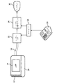
最初に図1を参照すると、本発明の原理に従って構成される超音波システムがブロック図形式で示される。プローブ10は米国特許7,927,280(Davidsen)に示すもののような仰角次元に湾曲した二次元アレイトランスデューサ12を持つ。アレイの素子はプローブ内でトランスデューサアレイの後ろに位置するマイクロビームフォーマ14に結合する。マイクロビームフォーマは時限送信パルスをアレイの素子に印加して、所望の方向及びアレイの前の三次元画像フィールド内の所望の焦点にビームを送信する。送信ビームからのエコーはアレイ素子によって受信され、マイクロビームフォーマ14のチャネルに結合され、ここでそれらは個別に遅延する。トランスデューサ素子のパッチからの遅延信号は結合されてそのパッチに対する部分合計信号を形成する。本明細書で使用される通り"パッチ"という語は、隣接しており一緒に作動される、又はそれらの信号をマイクロビームフォーマによって結合させて超音波システムビームフォーマに対する一つの信号を形成する、トランスデューサ素子のグループをあらわす。典型的な実施例において、結合はパッチの素子からの遅延信号を共通バスに結合することによってなされ、加算回路若しくは他の複雑な回路の必要性を除去する。各パッチのバスはケーブル16のコンダクタに結合され、これは部分合計パッチ信号をシステムメインフレームへ伝導する。システムメインフレームにおいて部分合計信号はデジタル化されシステムビームフォーマ22のチャネルへ結合され、これは各部分合計信号を適切に遅延させる。そして遅延部分合計信号は結合されてコヒーレントな操作及び集束受信ビームを形成する。3D画像フィールドからのビーム信号は信号及び画像プロセッサ24によって処理されて画像ディスプレイ30上のディスプレイ用の2D若しくは3D画像を生成する。プローブ選択、ビームステアリング及びフォーカシング、並びに信号及び画像処理などの超音波システムパラメータの制御はシステムの様々なモジュールに結合されるコントローラ26の制御下でなされる。プローブ10の場合この制御情報の一部はシステムメインフレームからケーブル16のデータ線を介して提供される。ユーザはこれらの操作パラメータを制御パネル20を用いて制御する。
Referring initially to FIG. 1, an ultrasound system constructed in accordance with the principles of the present invention is shown in block diagram form. The
図2は部分加算マイクロビームフォーマの概念を図示する。図2の描画は破線32と34によって三つのエリアに区分される。プローブ10の構成要素は線32の左に示され、システムメインフレームの構成要素は線34の右に示され、ケーブル16は二本の線の間に示される。プローブの二次元アレイ12は隣接トランスデューサ素子のパッチに分割される。アレイ12のパッチのうち5個が描画に示され、各々は9個の隣接素子を含む。パッチ12a、12c及び12eに対するマイクロビームフォーマチャネルが描画に示される。パッチ12aの9素子はDL1で示されるマイクロビームフォーマの9本の遅延線に結合される。同様にパッチ12c及び12eの9素子はDL2及びDL3で示される遅延線に結合される。これらの遅延線によって与えられる遅延はアレイのサイズ、素子ピッチ、パッチの間隔及び寸法、ビームステアリングの範囲などといった様々な変数の関数である。遅延線グループDL1、DL2及びDL3は各々それらの各パッチの素子からの信号をパッチに対する共通時間基準に遅延させる。そして各遅延線グループからの9個の遅延信号は各加算器Σによって結合されて素子のパッチからのアレイの部分合計信号を形成する。各部分合計信号は個別バス15a、15b及び15cに置かれ、これらの各々はケーブル16のコンダクタに結合し、これは部分合計信号をシステムメインフレームへ伝導する。システムメインフレームにおいて各部分合計信号はシステムビームフォーマ22の遅延線22a、22b、22cに印加される。これらの遅延線は部分合計信号をシステムビームフォーマ加算器22sの出力において共通ビームへ集束させる。そして完全に形成されたビームはさらなる処理及びディスプレイのために信号及び画像プロセッサへ転送される。図2の実施例は9素子パッチで示されるが、当然のことながら構成されるマイクロビームフォーマシステムは一般に12、20、48若しくは70素子若しくはそれ以上といった多数の素子を持つパッチを持つ。一つのパッチの素子は互いに隣接するか、間隙を介するか、又は"奇数"素子が1パッチに結合され、"偶数"素子が別のパッチに結合される格子縞模様に混ざり合ってもよい。パッチは正方形、長方形、ひし形、六角形、若しくはいかなる他の所望の形状であってもよい。
FIG. 2 illustrates the concept of a partial sum microbeamformer. The drawing in FIG. 2 is divided into three areas by
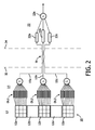
図3aは本発明の実施例で対処され得るマルチライン収集に関する問題を図示する。図3aは受信ビームプロファイル60、フィールド内で深度Xに至るまでエコーが受信される画像フィールドの面積若しくは体積のアウトラインを図示する。4本のマルチラインR1A、R2A、R1B、及びR2Bは、同じサイズの5個のパッチ40、42、44、46及び48に操作上分割されるアレイトランスデューサ12によって画像フィールドの中心における線の片側で受信されるものとする。図3aによって図示される通り、均一サイズのパッチのセット40‐48のビームプロファイル60は画像フィールドの中心において比較的狭い領域である。フィールド中心に最も近い二本のマルチラインR1A及びR1Bの最深深度のみが受信ビームプロファイル内にある。R1A及びR1Bマルチラインの範囲の残りと外側のマルチラインR2A及びR2Bの全範囲は受信ビームプロファイルを越えている。その結果これらのビームに対する受信信号は低強度で、弱く受信されたエコー信号をもたらし、これはこれらのマルチラインを用いて画像に薄暗く示されるのみになる。結果として生じるアーチファクトは得られる超音波画像においてチラチラ光る明暗の筋の束としてあらわれる。
FIG. 3a illustrates a problem with multi-line acquisition that may be addressed with embodiments of the present invention. FIG. 3a illustrates a receive
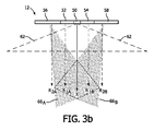
図3bでは、マルチラインに対する受信エコーのフルカバレッジを提供するために異なるサイズのパッチがアパーチャに段階的に追加される。中心パッチ50は最小であり、これは受信エコーに対する最大受光角と図3bに図示の通り深さは比較的浅いが横方向に広い受信ビームプロファイル62を与える。この最小中心パッチに対する受信ビームプロファイル62は全4本のマルチラインの近距離場をカバーするとみられる。エコーがより深い深度から受信されるので、中心パッチ50の両側に隣接パッチ52及び54が追加され、図3cに図示の通り全4本のマルチラインの中深度エコーの受信をカバーする。二つのより大きなパッチ52及び54の追加によって得られるビームプロファイル64A及び64Bは全4本のマルチラインに及ぶとみられる。より大きなパッチの各々からのビームプロファイルは走査領域の完全なカバレッジをもたらすために画像フィールドの中心の方へわずかに操作されるともみられる。最後に、最も外側の、さらに大きいパッチ56と58がアクティブアパーチャに追加される。これらのパッチで得られる受信ビームプロファイル66A及び66Bは図3bに示される。これらのビームプロファイルは画像フィールドの最大深度に及び、ビームプロファイルのいずれの最小受光角度も持つとみられ、また走査される領域のフルカバレッジを提供するために画像フィールドの中心の方へわずかに操作されるともみられる。異なるサイズのパッチ全部の組み合わせは、画像フィールドのフルカバレッジを提供し、ビームプロファイルの外側からのエコーの受信と、結果として生じるチラチラ光る画像アーチファクトを防ぐ。
In FIG. 3b, differently sized patches are added step by step to the aperture to provide full coverage of received echoes for multiple lines. The
図3b及び3cは本発明にかかるアレイトランスデューサの一次元のパッチのみを図示するが、図4‐6は方位角(水平)及び仰角(垂直)次元の両方における本発明の例示的な2Dアレイのパッチの次元を図示する2Dアレイ12の地形図を示す。これらの実施例に示す2Dアレイ12は各々方位角に160素子及び仰角に120素子、各2Dアレイにおいて合計19,200素子を有する。4個のマイクロビームフォーマASICが各アレイに対し初期部分ビームフォーミングを実行するために使用される。一つのASICはASIC境界を描く薄い線1‐1及び2‐2によって示される通りアレイの各四分円の後ろにある。図4及び5においてパッチはより暗い線によってアウトラインされる。図4の実施例では7行のパッチと16列のパッチがある。このフルアパーチャエリア36は、米国特許8,161,817(Savord)に記載の通りアパーチャが他の空間的に異なる走査線に対して2Dアレイにわたって段階的に平行移動され得るよう、2Dアレイ12の全領域未満を占めるとみなされる。図4におけるパッチのアパーチャ36は2Dアレイの左側にあるとみられ、その後次第に右側へ平行移動される。
3b and 3c illustrate only a one-dimensional patch of the array transducer according to the present invention, while FIGS. 4-6 illustrate an exemplary 2D array of the present invention in both azimuth (horizontal) and elevation (vertical) dimensions. A topographic map of the
図4のアパーチャ36におけるパッチはアパーチャの中心で最小であり、アパーチャの方位角エッジにおいて最大である。この実施例におけるパッチの各行は仰角次元に22素子の高さであり、従って各パッチは仰角に22素子である。方位角次元において中心の4パッチはパッチの中央4列にわたる角括弧70によって示される幅に3素子である。パッチの次の最外列72及び72'は4素子幅であり、次の列74及び74'は5素子幅である。パッチ列76及び76'は仰角に7素子でありパッチ列78及び78'は仰角に10素子である。次の外側列80及び80'は仰角に12素子でありアパーチャ36の仰角限界における最外列82及び82'は14素子幅である。図4の2Dアレイでの受信は最初に最も浅い深度の2若しくは4の小さい中央パッチを用いることによって開始し、それからエコーがパッチのフルアパーチャがアクティブになるまでより深い深度から受信され、最大所望受信深度まで使用されるにつれて、両側の次の隣接パッチに段階的にスイッチする。このパッチ配置の選択は各々撮像ボリュームにわたって方位角方向に広がる一連の平行な若しくはわずかに傾斜した面を走査するのによく適している。
The patch at
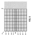
面が直交方向に走査される場合、各々仰角方向に広がる面のセット、図5に示すようなパッチ配置が使用され得る。図5の2Dアレイ12のアクティブアパーチャ36は方位角(図面において水平)方向に均一なサイズの仰角次元に広がる7列のパッチを持つ。仰角次元においてパッチサイジングはアパーチャの中心における最小の、各々仰角方向に6素子の高さである角括弧80で囲まれた3行のパッチから変化する。行82及び82'に示される次に外側のパッチは各々12素子の高さであり、次のパッチ84及び84'は各々19素子の高さである。各仰角極端における最も外側の2行、行86,88,86'及び88'は各々20素子の高さである。走査は中央の最小パッチ80、最初の一つ若しくは三つ全てでの受信を開始し、その後フィールドの最大深度におけるフルアパーチャ36にまでアクティブアパーチャを拡大するために中心から出て対称なペアで隣接パッチを段階的に追加することによって実行される。図4の2Dアレイと同様に、図5におけるアクティブアパーチャ36はアレイの前のボリューム領域における付加的な走査線を走査するために方位角方向にアレイにわたって平行移動され得る。
If the surfaces are scanned in orthogonal directions, a set of surfaces each extending in the elevation direction, a patch arrangement as shown in FIG. 5, can be used. The
図6は7個のビームフォーマチャネルのみを持つ超音波システムでのイメージングのためのこの19,200素子の2Dアレイ12の使用の一実施例を図示する。図6が示す通り、アクティブアパーチャ36には7パッチ91‐97しかなく、各々の部分的にビーム形成された合計信号は超音波システムの7チャネルビームフォーマのチャネルに結合される。前述の通り、7パッチのアクティブアパーチャはアレイ上の様々な他の位置へ平行移動され得る。この実施例における各パッチは1280素子、仰角方向に16素子及び方位角方向に80素子を有する。この構成のアパーチャは一般に方位角におけるマルチライン走査のために使用されないが、仰角における低次マルチライン収集のために使用され得る。
FIG. 6 illustrates one example of the use of this 19,200
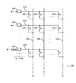
図7はプローブマイクロビームフォーマ14からのマイクロビーム形成された信号をシステムビームフォーマ22のチャネルへ選択的に結合するのに適したクロスポイントスイッチングマトリクスを図示する。2Dアレイトランスデューサの各素子、素子0、素子1、…素子3000などは、受信信号に適切な遅延を与えるマイクロビームフォーマ14の回路14'に結合される。各遅延素子信号は122、124、…126及び132、134、…136などの電子スイッチのアームへ線112、114、…120によって伝導される。線上の電子スイッチの一つはシステムチャネル0、システムチャネル1、…システムチャネル2などの選択されたシステムビームフォーマチャネルへその素子からの信号を結合するために閉じられる。クロスポイントスイッチングマトリクスにおける所望のスイッチを選択的に閉じることによって、任意の遅延素子信号がバス上の他の信号と合計するためにバス102、104、…110に置かれ、ビームフォーミング動作の完了のためにシステムビームフォーマ22のチャネルへ印加され得る。
FIG. 7 illustrates a crosspoint switching matrix suitable for selectively coupling the microbeamformed signal from the
本発明の使用はプローブが2Dアレイトランスデューサを使用するときに特に望ましいが、プローブ内のマイクロビームフォーマと作動する1Dアレイを用いるプローブにとっても有利である。かかる配置は2011年6月30日出願の米国特許出願番号61/503,329(Polandら)に記載のようなたった8、10、若しくは12チャネルのシステムビームフォーマなど、非常に低いチャネルカウントの超音波システムビームフォーマで作動され得る。本発明の実現はこれらのような削減されたチャネルカウントを持つシステムにおける1Dアレイ/マイクロビームフォーマプローブのマルチライン性能を改良し得る。 Although the use of the present invention is particularly desirable when the probe uses a 2D array transducer, it is also advantageous for a probe using a 1D array that works with a microbeamformer in the probe. Such an arrangement can be used with very low channel counts, such as only 8, 10, or 12 channel system beamformers as described in US patent application Ser. No. 61 / 503,329 (Poland et al.) Filed June 30, 2011. It can be operated with a sonic system beamformer. Implementations of the present invention can improve the multi-line performance of 1D array / microbeamformer probes in systems with these reduced channel counts.
Claims (15)
前記アレイの前記アパーチャを異なるサイズのパッチに構成し、各パッチは前記マイクロビームフォーマに結合するトランスデューサ素子のグループを有する、ステップと、
第1のサイズの一つ以上のパッチのアパーチャで浅いフィールド深度からエコーを受信するステップと、
前記第1のサイズと異なるサイズのパッチを追加するように前記アパーチャを拡大することによってより深いフィールド深度からエコーを受信するステップとを有する、
方法。 A method for controlling an aperture of an array transducer of an ultrasound probe, wherein the elements of the array are coupled to a microbeamformer in the probe that performs at least partial beamforming of a received echo signal;
Configuring the apertures of the array into patches of different sizes, each patch having a group of transducer elements coupled to the microbeamformer;
Receiving an echo from a shallow field depth with an aperture of one or more patches of a first size;
Receiving echoes from a deeper field depth by expanding the aperture to add a patch of a size different from the first size.
Method.
浅いフィールド深度からエコーを受信するステップが比較的小さいサイズの一つ以上のパッチでエコーを受信するステップをさらに有し、
より深いフィールド深度からエコーを受信するステップが前記比較的小さいサイズよりも大きいサイズのパッチを追加するように前記アパーチャを拡大するステップをさらに有する、
請求項1に記載の方法。 The array transducer further comprises a two-dimensional array of transducer elements;
Receiving the echo from a shallow field depth further comprises receiving the echo with one or more patches of relatively small size;
Receiving the echo from a deeper field depth further comprises expanding the aperture to add a patch of a size larger than the relatively small size;
The method of claim 1.
前記部分的にビームフォーミングされた信号のビームフォーミングを超音波システムビームフォーマで完了するステップをさらに有する、請求項1に記載の方法。 Partially beamforming signals from elements of the patch with the microbeamformer;
The method of claim 1, further comprising completing beamforming of the partially beamformed signal with an ultrasound system beamformer.
前記パッチ合計信号を超音波システムビームフォーマのチャネルへ結合するステップをさらに有する、請求項1に記載の方法。 Processing signals from the elements of the patch with a microbeamformer to form a patch total signal;
The method of claim 1, further comprising coupling the patch sum signal to a channel of an ultrasound system beamformer.
Applications Claiming Priority (3)
| Application Number | Priority Date | Filing Date | Title |
|---|---|---|---|
| US201261644524P | 2012-05-09 | 2012-05-09 | |
| US61/644,524 | 2012-05-09 | ||
| PCT/IB2013/053328 WO2013168045A1 (en) | 2012-05-09 | 2013-04-26 | Ultrasound transducer arrays with variable patch geometries |
Publications (2)
| Publication Number | Publication Date |
|---|---|
| JP2015515902A true JP2015515902A (en) | 2015-06-04 |
| JP6255390B2 JP6255390B2 (en) | 2017-12-27 |
Family
ID=48628750
Family Applications (1)
| Application Number | Title | Priority Date | Filing Date |
|---|---|---|---|
| JP2015510910A Active JP6255390B2 (en) | 2012-05-09 | 2013-04-26 | Ultrasonic transducer array with variable patch placement |
Country Status (7)
| Country | Link |
|---|---|
| US (3) | US9739885B2 (en) |
| EP (1) | EP2847615B1 (en) |
| JP (1) | JP6255390B2 (en) |
| CN (1) | CN104335066B (en) |
| BR (1) | BR112014027597A2 (en) |
| RU (1) | RU2638967C2 (en) |
| WO (1) | WO2013168045A1 (en) |
Cited By (1)
| Publication number | Priority date | Publication date | Assignee | Title |
|---|---|---|---|---|
| JP2020010762A (en) * | 2018-07-13 | 2020-01-23 | コニカミノルタ株式会社 | Ultrasonic signal processing device, ultrasonic diagnostic device and ultrasonic signal processing method |
Families Citing this family (8)
| Publication number | Priority date | Publication date | Assignee | Title |
|---|---|---|---|---|
| BR112014032126A2 (en) | 2012-06-28 | 2017-06-27 | Koninklijke Philips Nv | ultrasonic matrix set probe; and plurality of probes set of ultrasonic arrays |
| US9286418B1 (en) * | 2014-05-01 | 2016-03-15 | The United States Of America As Represented By The Secretary Of The Navy | Method for designing an acoustic array |
| EP3389500A4 (en) * | 2015-12-18 | 2019-01-02 | Ursus Medical LLC | Ultrasound beamforming system and method with reconfigurable aperture |
| JP6933102B2 (en) * | 2017-11-20 | 2021-09-08 | コニカミノルタ株式会社 | Ultrasonic signal processing device and ultrasonic signal processing method |
| RU192949U1 (en) * | 2018-12-11 | 2019-10-08 | Публичное акционерное общество "Транснефть" (ПАО "Транснефть") | Antenna unit for a mobile complex for determining the level and volume of bottom sediments in oil tanks |
| EP3900846A1 (en) * | 2020-04-21 | 2021-10-27 | Koninklijke Philips N.V. | Acoustic imaging probe with a transducer element |
| EP4153364A1 (en) * | 2020-05-22 | 2023-03-29 | Deepsight Technology, Inc. | Mixed ultrasound transducer arrays |
| JPWO2022230601A1 (en) * | 2021-04-30 | 2022-11-03 |
Citations (2)
| Publication number | Priority date | Publication date | Assignee | Title |
|---|---|---|---|---|
| JP2009528115A (en) * | 2006-03-01 | 2009-08-06 | コーニンクレッカ フィリップス エレクトロニクス エヌ ヴィ | Linear array ultrasonic transducer with variable patch boundaries |
| JP2012005600A (en) * | 2010-06-23 | 2012-01-12 | Toshiba Corp | Ultrasonic diagnostic apparatus |
Family Cites Families (31)
| Publication number | Priority date | Publication date | Assignee | Title |
|---|---|---|---|---|
| US4797682A (en) * | 1987-06-08 | 1989-01-10 | Hughes Aircraft Company | Deterministic thinned aperture phased antenna array |
| US5229933A (en) | 1989-11-28 | 1993-07-20 | Hewlett-Packard Company | 2-d phased array ultrasound imaging system with distributed phasing |
| US5113706A (en) * | 1990-07-03 | 1992-05-19 | Hewlett-Packard Company | Ultrasound system with dynamic transmit focus |
| US5318033A (en) | 1992-04-17 | 1994-06-07 | Hewlett-Packard Company | Method and apparatus for increasing the frame rate and resolution of a phased array imaging system |
| US5677491A (en) * | 1994-08-08 | 1997-10-14 | Diasonics Ultrasound, Inc. | Sparse two-dimensional transducer array |
| WO1997032277A1 (en) * | 1996-02-29 | 1997-09-04 | Acuson Corporation | Multiple ultrasound image registration system, method and transducer |
| US5911221A (en) * | 1996-06-25 | 1999-06-15 | Siemens Medical Systems Inc. | Static scanhead switching along elevation for forming ultrasound beam line |
| US5832923A (en) * | 1996-12-11 | 1998-11-10 | General Electric Company | Utrasound imaging system architecture employing switched transducer elements |
| US5882309A (en) * | 1997-05-07 | 1999-03-16 | General Electric Company | Multi-row ultrasonic transducer array with uniform elevator beamwidth |
| KR100355719B1 (en) * | 2000-06-10 | 2002-10-11 | 주식회사 메디슨 | Ultrasound receive beamforming apparatus using multi-tier delay devices |
| KR100406099B1 (en) * | 2001-09-05 | 2003-11-14 | 주식회사 메디슨 | Ultrasound image forming apparatus and method using multi-level pulse compressor |
| US6730033B2 (en) * | 2002-05-16 | 2004-05-04 | Siemens Medical Systems, Inc. | Two dimensional array and methods for imaging in three dimensions |
| US6629929B1 (en) * | 2002-11-08 | 2003-10-07 | Koninklijke Philips Electronics N.V. | Method and apparatus for automatically setting the transmit aperture and apodization of an ultrasound transducer array |
| EP1491913B1 (en) * | 2003-06-25 | 2006-09-27 | Aloka Co. Ltd. | Ultrasound diagnosis apparatus comprising a 2D transducer with variable subarrays |
| US7273455B2 (en) * | 2003-07-17 | 2007-09-25 | Angelsen Bjoern A J | Corrections for wavefront aberrations in ultrasound imaging |
| US20050131299A1 (en) * | 2003-12-10 | 2005-06-16 | Brent Robinson | Differential partial beamforming |
| US7635334B2 (en) * | 2004-04-28 | 2009-12-22 | Siemens Medical Solutions Usa, Inc. | Dynamic sub-array mapping systems and methods for ultrasound imaging |
| EP1838462B1 (en) * | 2005-01-11 | 2018-08-08 | Koninklijke Philips N.V. | Redistribution interconnect for microbeamformer(s) and a medical ultrasound system |
| EP1913419B1 (en) | 2005-08-05 | 2014-05-07 | Koninklijke Philips N.V. | Curved 2-d array ultrasound transducer and method for volumetric imaging |
| US20080021432A1 (en) | 2005-12-22 | 2008-01-24 | Kline Mark J | Relative stiffness fasteners |
| US8161817B2 (en) | 2006-03-01 | 2012-04-24 | Koninklijke Philips Electronics N.V | Linear array ultrasound transducer with microbeamformer |
| WO2007133881A2 (en) * | 2006-05-12 | 2007-11-22 | Koninklijke Philips Electronics, N.V. | Incoherent retrospective dynamic transmit focusing |
| JP4842726B2 (en) * | 2006-07-18 | 2011-12-21 | 富士フイルム株式会社 | Ultrasonic inspection equipment |
| CN101209211B (en) * | 2006-12-30 | 2011-03-09 | 深圳迈瑞生物医疗电子股份有限公司 | Synthesis method and device for digitalization ultrasonic beam with adjustable receiver aperture |
| US8096951B2 (en) * | 2007-06-28 | 2012-01-17 | General Electric Company | Transmit beamforming in 3-dimensional ultrasound |
| US20120143100A1 (en) | 2009-08-14 | 2012-06-07 | University Of Southern California | Extended depth-of-focus high intensity ultrasonic transducer |
| EP2473111B1 (en) * | 2009-09-03 | 2016-03-16 | Koninklijke Philips N.V. | Ultrasound probe with large field of view and method for fabricating such ultrasound probe |
| CN101893705B (en) * | 2010-06-30 | 2013-02-27 | 重庆大学 | Control method of dynamic aperture based on ultrasonic imaging system |
| US9775585B2 (en) * | 2011-06-15 | 2017-10-03 | Toshiba Medical Systems Corporation | Variable power saving processing scheme for ultrasound beamformer functionality |
| CN103635829B (en) | 2011-06-30 | 2016-04-27 | 皇家飞利浦有限公司 | There is the two-dimensional ultrasound diagnostic imaging system in two beam-shaper stages |
| KR20140054645A (en) | 2012-10-29 | 2014-05-09 | 한국전자통신연구원 | Diagnosis apparatus for alzheimer's disease and method of diagnosing using the same |
-
2013
- 2013-04-26 RU RU2014149238A patent/RU2638967C2/en active
- 2013-04-26 JP JP2015510910A patent/JP6255390B2/en active Active
- 2013-04-26 WO PCT/IB2013/053328 patent/WO2013168045A1/en active Application Filing
- 2013-04-26 CN CN201380024181.5A patent/CN104335066B/en active Active
- 2013-04-26 US US14/397,494 patent/US9739885B2/en active Active
- 2013-04-26 EP EP13729440.1A patent/EP2847615B1/en active Active
- 2013-04-26 BR BR112014027597A patent/BR112014027597A2/en not_active Application Discontinuation
-
2017
- 2017-06-08 US US15/616,998 patent/US10168428B2/en active Active
-
2018
- 2018-12-03 US US16/207,344 patent/US11391838B2/en active Active
Patent Citations (2)
| Publication number | Priority date | Publication date | Assignee | Title |
|---|---|---|---|---|
| JP2009528115A (en) * | 2006-03-01 | 2009-08-06 | コーニンクレッカ フィリップス エレクトロニクス エヌ ヴィ | Linear array ultrasonic transducer with variable patch boundaries |
| JP2012005600A (en) * | 2010-06-23 | 2012-01-12 | Toshiba Corp | Ultrasonic diagnostic apparatus |
Cited By (2)
| Publication number | Priority date | Publication date | Assignee | Title |
|---|---|---|---|---|
| JP2020010762A (en) * | 2018-07-13 | 2020-01-23 | コニカミノルタ株式会社 | Ultrasonic signal processing device, ultrasonic diagnostic device and ultrasonic signal processing method |
| JP7124505B2 (en) | 2018-07-13 | 2022-08-24 | コニカミノルタ株式会社 | Ultrasonic signal processing device, ultrasonic diagnostic device, and ultrasonic signal processing method |
Also Published As
| Publication number | Publication date |
|---|---|
| CN104335066A (en) | 2015-02-04 |
| US20190113620A1 (en) | 2019-04-18 |
| RU2638967C2 (en) | 2017-12-19 |
| WO2013168045A1 (en) | 2013-11-14 |
| RU2014149238A (en) | 2016-07-10 |
| US10168428B2 (en) | 2019-01-01 |
| CN104335066B (en) | 2018-04-27 |
| EP2847615B1 (en) | 2019-04-03 |
| JP6255390B2 (en) | 2017-12-27 |
| US11391838B2 (en) | 2022-07-19 |
| US9739885B2 (en) | 2017-08-22 |
| US20150085617A1 (en) | 2015-03-26 |
| BR112014027597A2 (en) | 2017-06-27 |
| EP2847615A1 (en) | 2015-03-18 |
| US20170269208A1 (en) | 2017-09-21 |
Similar Documents
| Publication | Publication Date | Title |
|---|---|---|
| JP6255390B2 (en) | Ultrasonic transducer array with variable patch placement | |
| JP5371448B2 (en) | Ultrasound imaging system and method for translating receiving aperture | |
| JP4675444B2 (en) | Apparatus and method for multiplexing transducers | |
| JP6165855B2 (en) | Two-dimensional ultrasonic transducer array operable with different ultrasonic systems | |
| US20140155751A1 (en) | Method and system for element-by-element flexible subarray beamforming | |
| US6730033B2 (en) | Two dimensional array and methods for imaging in three dimensions | |
| US10245005B2 (en) | Ultrasound transducer probe with microbeamformer for multiline imaging | |
| JP6960938B2 (en) | 2D ultrasonic array transducer with 1D patch | |
| JP7401462B2 (en) | Ultrasonic imaging with sparse sampling and related devices, systems and methods | |
| JP7044723B2 (en) | High-speed synthetic focused ultrasound imaging with large linear array | |
| JP4599408B2 (en) | Ultrasonic diagnostic equipment | |
| WO2014088079A1 (en) | Ultrasonic diagnostic device and ultrasonic probe | |
| O'Donnell et al. | Aberration correction on a two-dimensional anisotropic phased array (medical US imaging) | |
| US20200297317A1 (en) | Ultrasonic diagnostic device and transmission control method | |
| WO2017220354A1 (en) | Rapid synthetic focus ultrasonic imaging with large linear arrays |
Legal Events
| Date | Code | Title | Description |
|---|---|---|---|
| A521 | Request for written amendment filed |
Free format text: JAPANESE INTERMEDIATE CODE: A523 Effective date: 20150320 |
|
| A621 | Written request for application examination |
Free format text: JAPANESE INTERMEDIATE CODE: A621 Effective date: 20160425 |
|
| RD04 | Notification of resignation of power of attorney |
Free format text: JAPANESE INTERMEDIATE CODE: A7424 Effective date: 20170214 |
|
| A977 | Report on retrieval |
Free format text: JAPANESE INTERMEDIATE CODE: A971007 Effective date: 20170227 |
|
| A131 | Notification of reasons for refusal |
Free format text: JAPANESE INTERMEDIATE CODE: A131 Effective date: 20170328 |
|
| A601 | Written request for extension of time |
Free format text: JAPANESE INTERMEDIATE CODE: A601 Effective date: 20170623 |
|
| A521 | Request for written amendment filed |
Free format text: JAPANESE INTERMEDIATE CODE: A523 Effective date: 20170927 |
|
| TRDD | Decision of grant or rejection written | ||
| A01 | Written decision to grant a patent or to grant a registration (utility model) |
Free format text: JAPANESE INTERMEDIATE CODE: A01 Effective date: 20171107 |
|
| A61 | First payment of annual fees (during grant procedure) |
Free format text: JAPANESE INTERMEDIATE CODE: A61 Effective date: 20171204 |
|
| R150 | Certificate of patent or registration of utility model |
Ref document number: 6255390 Country of ref document: JP Free format text: JAPANESE INTERMEDIATE CODE: R150 |
|
| R250 | Receipt of annual fees |
Free format text: JAPANESE INTERMEDIATE CODE: R250 |
|
| R250 | Receipt of annual fees |
Free format text: JAPANESE INTERMEDIATE CODE: R250 |
|
| R250 | Receipt of annual fees |
Free format text: JAPANESE INTERMEDIATE CODE: R250 |
|
| R250 | Receipt of annual fees |
Free format text: JAPANESE INTERMEDIATE CODE: R250 |