JP6960938B2 - 2D ultrasonic array transducer with 1D patch - Google Patents
2D ultrasonic array transducer with 1D patch Download PDFInfo
- Publication number
- JP6960938B2 JP6960938B2 JP2018551376A JP2018551376A JP6960938B2 JP 6960938 B2 JP6960938 B2 JP 6960938B2 JP 2018551376 A JP2018551376 A JP 2018551376A JP 2018551376 A JP2018551376 A JP 2018551376A JP 6960938 B2 JP6960938 B2 JP 6960938B2
- Authority
- JP
- Japan
- Prior art keywords
- imaging system
- diagnostic imaging
- subpatch
- signal
- ultrasonic diagnostic
- Prior art date
- Legal status (The legal status is an assumption and is not a legal conclusion. Google has not performed a legal analysis and makes no representation as to the accuracy of the status listed.)
- Active
Links
Images


Classifications
-
- A—HUMAN NECESSITIES
- A61—MEDICAL OR VETERINARY SCIENCE; HYGIENE
- A61B—DIAGNOSIS; SURGERY; IDENTIFICATION
- A61B8/00—Diagnosis using ultrasonic, sonic or infrasonic waves
- A61B8/44—Constructional features of the ultrasonic, sonic or infrasonic diagnostic device
- A61B8/4483—Constructional features of the ultrasonic, sonic or infrasonic diagnostic device characterised by features of the ultrasound transducer
- A61B8/4488—Constructional features of the ultrasonic, sonic or infrasonic diagnostic device characterised by features of the ultrasound transducer the transducer being a phased array
-
- G—PHYSICS
- G01—MEASURING; TESTING
- G01S—RADIO DIRECTION-FINDING; RADIO NAVIGATION; DETERMINING DISTANCE OR VELOCITY BY USE OF RADIO WAVES; LOCATING OR PRESENCE-DETECTING BY USE OF THE REFLECTION OR RERADIATION OF RADIO WAVES; ANALOGOUS ARRANGEMENTS USING OTHER WAVES
- G01S15/00—Systems using the reflection or reradiation of acoustic waves, e.g. sonar systems
- G01S15/88—Sonar systems specially adapted for specific applications
- G01S15/89—Sonar systems specially adapted for specific applications for mapping or imaging
- G01S15/8906—Short-range imaging systems; Acoustic microscope systems using pulse-echo techniques
- G01S15/8909—Short-range imaging systems; Acoustic microscope systems using pulse-echo techniques using a static transducer configuration
- G01S15/8915—Short-range imaging systems; Acoustic microscope systems using pulse-echo techniques using a static transducer configuration using a transducer array
- G01S15/8925—Short-range imaging systems; Acoustic microscope systems using pulse-echo techniques using a static transducer configuration using a transducer array the array being a two-dimensional transducer configuration, i.e. matrix or orthogonal linear arrays
-
- A—HUMAN NECESSITIES
- A61—MEDICAL OR VETERINARY SCIENCE; HYGIENE
- A61B—DIAGNOSIS; SURGERY; IDENTIFICATION
- A61B8/00—Diagnosis using ultrasonic, sonic or infrasonic waves
- A61B8/13—Tomography
- A61B8/14—Echo-tomography
- A61B8/145—Echo-tomography characterised by scanning multiple planes
-
- A—HUMAN NECESSITIES
- A61—MEDICAL OR VETERINARY SCIENCE; HYGIENE
- A61B—DIAGNOSIS; SURGERY; IDENTIFICATION
- A61B8/00—Diagnosis using ultrasonic, sonic or infrasonic waves
- A61B8/46—Ultrasonic, sonic or infrasonic diagnostic devices with special arrangements for interfacing with the operator or the patient
- A61B8/461—Displaying means of special interest
- A61B8/463—Displaying means of special interest characterised by displaying multiple images or images and diagnostic data on one display
-
- A—HUMAN NECESSITIES
- A61—MEDICAL OR VETERINARY SCIENCE; HYGIENE
- A61B—DIAGNOSIS; SURGERY; IDENTIFICATION
- A61B8/00—Diagnosis using ultrasonic, sonic or infrasonic waves
- A61B8/46—Ultrasonic, sonic or infrasonic diagnostic devices with special arrangements for interfacing with the operator or the patient
- A61B8/461—Displaying means of special interest
- A61B8/466—Displaying means of special interest adapted to display 3D data
-
- A—HUMAN NECESSITIES
- A61—MEDICAL OR VETERINARY SCIENCE; HYGIENE
- A61B—DIAGNOSIS; SURGERY; IDENTIFICATION
- A61B8/00—Diagnosis using ultrasonic, sonic or infrasonic waves
- A61B8/54—Control of the diagnostic device
-
- G—PHYSICS
- G01—MEASURING; TESTING
- G01S—RADIO DIRECTION-FINDING; RADIO NAVIGATION; DETERMINING DISTANCE OR VELOCITY BY USE OF RADIO WAVES; LOCATING OR PRESENCE-DETECTING BY USE OF THE REFLECTION OR RERADIATION OF RADIO WAVES; ANALOGOUS ARRANGEMENTS USING OTHER WAVES
- G01S15/00—Systems using the reflection or reradiation of acoustic waves, e.g. sonar systems
- G01S15/88—Sonar systems specially adapted for specific applications
- G01S15/89—Sonar systems specially adapted for specific applications for mapping or imaging
- G01S15/8906—Short-range imaging systems; Acoustic microscope systems using pulse-echo techniques
- G01S15/8909—Short-range imaging systems; Acoustic microscope systems using pulse-echo techniques using a static transducer configuration
- G01S15/8915—Short-range imaging systems; Acoustic microscope systems using pulse-echo techniques using a static transducer configuration using a transducer array
- G01S15/8927—Short-range imaging systems; Acoustic microscope systems using pulse-echo techniques using a static transducer configuration using a transducer array using simultaneously or sequentially two or more subarrays or subapertures
-
- G—PHYSICS
- G01—MEASURING; TESTING
- G01S—RADIO DIRECTION-FINDING; RADIO NAVIGATION; DETERMINING DISTANCE OR VELOCITY BY USE OF RADIO WAVES; LOCATING OR PRESENCE-DETECTING BY USE OF THE REFLECTION OR RERADIATION OF RADIO WAVES; ANALOGOUS ARRANGEMENTS USING OTHER WAVES
- G01S7/00—Details of systems according to groups G01S13/00, G01S15/00, G01S17/00
- G01S7/52—Details of systems according to groups G01S13/00, G01S15/00, G01S17/00 of systems according to group G01S15/00
- G01S7/52017—Details of systems according to groups G01S13/00, G01S15/00, G01S17/00 of systems according to group G01S15/00 particularly adapted to short-range imaging
- G01S7/52079—Constructional features
- G01S7/5208—Constructional features with integration of processing functions inside probe or scanhead
-
- G—PHYSICS
- G01—MEASURING; TESTING
- G01S—RADIO DIRECTION-FINDING; RADIO NAVIGATION; DETERMINING DISTANCE OR VELOCITY BY USE OF RADIO WAVES; LOCATING OR PRESENCE-DETECTING BY USE OF THE REFLECTION OR RERADIATION OF RADIO WAVES; ANALOGOUS ARRANGEMENTS USING OTHER WAVES
- G01S7/00—Details of systems according to groups G01S13/00, G01S15/00, G01S17/00
- G01S7/52—Details of systems according to groups G01S13/00, G01S15/00, G01S17/00 of systems according to group G01S15/00
- G01S7/52017—Details of systems according to groups G01S13/00, G01S15/00, G01S17/00 of systems according to group G01S15/00 particularly adapted to short-range imaging
- G01S7/52085—Details related to the ultrasound signal acquisition, e.g. scan sequences
- G01S7/52095—Details related to the ultrasound signal acquisition, e.g. scan sequences using multiline receive beamforming
Description
本発明は、医用診断超音波システムに関し、特に1次元アレイパッチで動作させられる2次元アレイ(マトリクスアレイ)トランスデューサプローブを有する超音波システムに関する。 The present invention relates to a medical diagnostic ultrasound system, particularly to an ultrasound system having a two-dimensional array (matrix array) transducer probe operated by a one-dimensional array patch.
超音波アレイトランスデューサは、ビームフォーマを使用して、トランスデューサアレイの素子から受信される超音波エコー信号を送受信し、適切に遅延させ、合計する。遅延は、ビームフォーマによって形成されるビームの方向(ステアリング)及び焦点深度を考慮して選択される。各素子からの信号が、ビームフォーマのチャネルによって適切に遅延された後、遅延された信号は組み合わされて、適切にステアリング且つ集束されたコヒーレントエコー信号のビームが形成される。超音波ビームの送信中、個々の素子の作動時間は、送信ビームの受信遅延、ステアリング及び集束の補数である。遅延の選択は、アレイ素子と、ビームによってインタロゲートされる画像フィールドとの形状から決定可能であることが分かっている。 The ultrasonic array transducer uses a beamformer to send, receive, delay, and sum the ultrasonic echo signals received from the elements of the transducer array. The delay is selected in consideration of the direction (steering) and depth of focus of the beam formed by the beam former. After the signal from each element is properly delayed by the beamformer channel, the delayed signals are combined to form a beam of properly steered and focused coherent echo signals. During the transmission of the ultrasonic beam, the operating time of the individual elements is the complement of the transmission beam reception delay, steering and focusing. It has been found that the choice of delay can be determined from the shape of the array element and the image field interlaced by the beam.
従来の超音波システムでは、アレイトランスデューサは、プローブ内にあり、プローブは、撮像中に患者の身体に接して置かれ、同調素子、スイッチ及び増幅器デバイスといった幾つかの電子コンポーネントを含む。遅延及び信号合成は、超音波システムメインフレームに含まれるビームフォーマによって行われる。プローブは、ケーブルによって超音波システムメインフレームに接続される。 In conventional ultrasound systems, the array transducer is inside the probe, which is placed in contact with the patient's body during imaging and includes several electronic components such as tuning elements, switches and amplifier devices. Delay and signal synthesis are performed by a beamformer included in the ultrasonic system mainframe. The probe is connected to the ultrasonic system mainframe by a cable.
アレイトランスデューサ及びビームフォーマの上記システムアーキテクチャは、トランスデューサ素子の数とビームフォーマチャネルの数とが略同じである1次元(1D)トランスデューサアレイには全く十分である。トランスデューサ素子の数が、ビームフォーマチャネルの数を上回ると、通常、多重化が採用され、任意の時点において、トランスデューサ素子の総数のサブセットしかビームフォーマに接続できない。1Dアレイにおける素子の数は、100未満から数百に及び、典型的なビームフォーマは、128個のビームフォーマチャネルを有する。このシステムアーキテクチャソリューションは、2次元(2D)又は3次元(3D)撮像用の2次元アレイトランスデューサの出現によって支持されなくなった。これは、2Dアレイトランスデューサは、ボリュメトリック領域全体でアジマス方向及びエレベーション方向の両方にビームをステアリング及び集束させるからである。このビーム形成に必要なトランスデューサ素子の数は、通常、千単位である。したがって、問題の核心は、プローブをビームフォーマがあるシステムメインフレームに接続するケーブルとなる。数千の導体からなるケーブルは、最も細い導電フィラメントを用いたとしても、太く、扱いにくくなり、プローブの操作が、不可能ではないにしても厄介になる。 The system architecture of array transducers and beamformers is quite sufficient for one-dimensional (1D) transducer arrays where the number of transducer elements and the number of beamformer channels are approximately the same. When the number of transducer elements exceeds the number of beamformer channels, multiplexing is usually employed and only a subset of the total number of transducer elements can be connected to the beamformer at any given time. The number of elements in a 1D array ranges from less than 100 to hundreds, and a typical beamformer has 128 beamformer channels. This system architecture solution has become unsupported with the advent of two-dimensional array transducers for two-dimensional (2D) or three-dimensional (3D) imaging. This is because the 2D array transducer steers and focuses the beam in both the azimuth and elevation directions over the entire volumetric region. The number of transducer elements required for this beam formation is usually in the thousands. Therefore, the core of the problem is the cable that connects the probe to the system mainframe where the beamformer is located. Cables of thousands of conductors, even with the thinnest conductive filaments, are thick and unwieldy, making probe operation awkward, if not impossible.
この問題に対するソリューションは、米国特許第5,229,933号(Larson、III)に説明されるように、ビーム形成の少なくとも一部をプローブ自体内で行うことである。この特許に示される超音波システムでは、ビーム形成は、プローブとシステムメインフレームとで分割される。素子のグループによる初期ビーム形成が、プローブ内で行われ、部分的にビーム形成された合計が生成される。これらの部分的にビーム形成された合計は、トランスデューサ素子の数よりも数が少なく、妥当な方向のケーブルを通りシステムメインフレームに結合される。システムメインフレームにおいて、ビーム形成処理が完了され、最終ビームが生成される。プローブ内の部分ビーム形成は、Larson,IIIが言うところのイントラグループプロセッサによって、アレイトランスデューサに取り付けられる超小型電子機器の形のマイクロビームフォーマにおいて行われる。米国特許5,997,479号(Savord他)、米国特許第6,013,032号(Savord)、米国特許第6,126,602号(Savord他)及び米国特許第6,375,617号(Fraser)も参照されたい。2Dトランスデューサアレイの何千もの素子とマイクロビームフォーマとの間の何千もの接続は、非常に小さい方向の超小型回路及びアレイピッチで行われる一方で、マイクロビームフォーマとシステムメインフレームのビームフォーマとの間のはるかに少ないケーブル接続は、従来のケーブル技術によって行われる。米国特許出願公開第60/706,190号(Kunkel)及び第60/706,208号(Davidsen)に示される曲面アレイといったように、様々な平面及び曲面アレイフォーマットをマイクロビームフォーマと共に使用することができる。 The solution to this problem is to perform at least part of the beam formation within the probe itself, as described in US Pat. No. 5,229,933 (Larson, III). In the ultrasonic system presented in this patent, beam formation is divided between the probe and the system mainframe. Initial beam formation by a group of devices takes place within the probe, producing a partially beam-formed sum. These partially beamed sums are fewer than the number of transducer elements and are coupled to the system mainframe through cables in the appropriate direction. In the system mainframe, the beam forming process is completed and the final beam is generated. Partial beam formation within the probe is performed in what Larson, III calls an intragroup processor, in a microbeam former in the form of a microelectronic device attached to an array transducer. U.S. Pat. Nos. 5,997,479 (Savord et al.), U.S. Pat. No. 6,013,032 (Savord), U.S. Pat. No. 6,126,602 (Savord et al.) And U.S. Pat. See also Fraser). Thousands of connections between the thousands of elements in a 2D transducer array and the microbeamformer are made with very small directional microcircuits and array pitches, while the microbeamformer and system mainframe beamformers Much less cable connection between is made by conventional cable technology. Various planar and curved array formats can be used with microbeam formers, such as the curved arrays shown in U.S. Patent Application Publications 60 / 706, 190 (Kunkel) and 60 / 706,208 (Davidsen). can.
上記特許に示されるマイクロビームフォーマは、「パッチ」と呼ばれる連続的なトランスデューサ素子のグループから、部分的に遅延された合計信号を形成することによって、動作する。1パッチのすべての素子によって受信される信号は、マイクロビームフォーマによって適切に個別に遅延され、部分和信号となるように組み合わされる。通常、パッチは、素子の4×6グループ又は8×12グループといった素子の小さい2次元グループで形成される。これは、3Dボリューム走査中のフェーズドアレイ動作に対してうまく機能し、ボリュームのリアルタイム走査が可能となる。しかし、2D撮像では、このようなパッチの幅が、走査領域の画像の解像度を制限する。これは、撮像のフレームレートを向上させるためにマルチライン受信を行う場合に特に言えることである。したがって、マルチライン受信によってより高いフレームレートを達成可能であり、また、これを、上記2Dアレイトランスデューサ画像の解像度を低下させることなく、好適には、向上させて行うことが望ましい。 The microbeam former shown in the above patent operates by forming a partially delayed total signal from a group of continuous transducer elements called "patches". The signals received by all the elements in one patch are appropriately individually delayed by the microbeam former and combined to form a partial sum signal. Patches are typically formed in small two-dimensional groups of elements, such as 4x6 or 8x12 groups of elements. This works well for phased array operations during 3D volume scanning, allowing real-time scanning of the volume. However, in 2D imaging, the width of such patches limits the resolution of the image in the scanning area. This is especially true when multi-line reception is performed to improve the frame rate of imaging. Therefore, it is possible to achieve a higher frame rate by multi-line reception, and it is desirable to improve this without lowering the resolution of the 2D array transducer image.
本発明の原理によれば、1×Nパッチで動作させられる2Dアレイトランスデューサを有する診断超音波システムが説明される。これらのパッチは、単一の素子分の幅しかない。パッチの「N」長さは、走査された2D画像平面の1つの方向(例えばエレベーション方向)に延在し、上記単一の素子分の幅は、もう1つの(例えば横又はアジマス)方向に延在する。集束は、マイクロビームフォーマによって、1つの方向において、各パッチに沿って行われ、もう1つの方向における集束は、システムビームフォーマによって行われる。第2の方向における各パッチの最小幅は、2D画像の平面における高解像度画像の生成を可能にし、これには、高フレームレート撮像のための高解像度マルチライン受信が含まれる。 According to the principles of the present invention, a diagnostic ultrasound system with a 2D array transducer operated in a 1xN patch will be described. These patches are only as wide as a single element. The "N" length of the patch extends in one direction (eg, elevation) of the scanned 2D image plane, and the width of the single element is in the other (eg, lateral or azimuth) direction. Extends to. Focusing is done by the microbeamformer in one direction along each patch, and focusing in the other direction is done by the system beamformer. The minimum width of each patch in the second direction allows the generation of high resolution images in the plane of the 2D image, including high resolution multiline reception for high frame rate imaging.
図1を最初に参照するに、本発明の原理に従って構成された超音波システムがブロック図で示される。プローブ10は、平面であっても、本例に示されるように、曲面であってもよい2次元アレイトランスデューサ12を有する。アレイの素子は、トランスデューサアレイの後方で、プローブ内にあるマイクロビームフォーマ14に結合される。マイクロビームフォーマは、プローブ内にあり、2Dアレイトランスデューサ12の素子に結合されるビーム形成チャネルを有する集積回路である。マイクロビームフォーマは、アレイの各パッチの素子に、時限送信パルスを適用し、アレイの前にある画像フィールド内の所望の方向及び所望の焦点に向けてビームを送信する。エレベーション方向における送信ビームのプロファイルは、点焦点、平面波又は任意の中間ビームプロファイルを示すことができる。送信されたビームから、細胞及び組織によって戻されるエコーは、アレイ素子によって受信され、マイクロビームフォーマ14のチャネルに結合される。エコーは、マイクロビームフォーマ14において、個別に遅延される。トランスデューサ素子の連続的なパッチからの遅延された信号は組み合わされて、当該パッチの部分和信号が形成される。アナログマイクロビームフォーマ実施態様では、組み合わせは、パッチの素子からの遅延された信号を共通バスに結合することによって行われ、加算回路が不要となる。各パッチのバスは、ケーブル16の導体に結合される。導体は、部分和パッチ信号をシステムメインフレームに伝える。システムメインフレーム内では、アナログ部分和信号が、デジタル化され、システムビームフォーマ22のチャネルに結合される。システムビームフォーマ22は、各部分和信号を適切に遅延させる。次に、遅延された部分和信号は組み合わされて、コヒーレントなステアリング及び集束された受信ビームが形成される。システムビームフォーマは、当技術分野においてよく知られており、電子ハードウェアコンポーネント、ソフトウェア制御ハードウェア又はビーム形成アルゴリズムを実行するマイクロプロセッサを含んでよい。デジタルビームフォーマの場合、ビームフォーマは、マイクロビームフォーマからのアナログ信号を、サンプリングされたデジタルエコーデータに変換するA/D変換器を含む。ビームフォーマは、通常、エコーデータをコヒーレントエコー信号データに処理するために、1つ以上のマイクロプロセッサ、シフトレジスタ、及び/又は、デジタル若しくはアナログメモリを含む。遅延は、受信信号のサンプリングの時間、メモリに一時的に記憶されるデータの書き込み/読み出し間隔、又は、米国特許第4,173,007号(McKeighen他)に説明されるように、シフトレジスタの長さ、即ち、クロックレートによって、といったように、様々な手段でもたらされる。画像フィールドからのビーム信号は、信号及び画像プロセッサ24によって処理され、画像ディスプレイ30に表示するための2D又は3D画像が生成される。信号及び画像プロセッサは、電子ハードウェアコンポーネント、ソフトウェア制御ハードウェア又は画像処理アルゴリズムを実行するマイクロプロセッサを含んでよい。信号及び画像プロセッサは更に、通常、スキャンコンバータといった、受信エコーデータを、所望の表示形式の画像の画像データに処理する専用ハードウェア又はソフトウェアも含む。
With reference to FIG. 1 first, an ultrasonic system constructed according to the principles of the present invention is shown in a block diagram. The
プローブ選択、ビームステアリング及び集束、並びに、信号及び画像処理といった超音波システムパラメータの制御は、システムの様々なモジュールに結合されるシステムコントローラ26の制御下で行われる。システムコントローラは、ASIC回路又はマイクロプロセッサ回路、及び、RAM、ROM又はディスクドライブといったソフトウェアデータストレージデバイスによって形成される。プローブ10の場合、この制御情報の一部は、システムメインフレームからマイクロビームフォーマに、ケーブル16のデータ線を介して提供され、特定の走査手順に必要とされる2Dアレイの動作のためにマイクロビームフォーマが調整される。ユーザは、これらの操作パラメータを、制御パネル20によって制御する。この基本的な超音波システムのブロック図は、ビーム形成を、素子のパッチからの信号のビーム形成を行うマイクロビームフォーマと、パッチからの部分和信号を組み合わせることによってビーム形成処理を完了するシステムビームフォーマとの間で分割することについて説明したものである。
Control of ultrasonic system parameters such as probe selection, beam steering and focusing, and signal and image processing is performed under the control of a
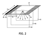
図2は、本発明の原理に従って動作する2Dアレイトランスデューサ12を示す。アレイ12は、横(アジマス(Az))方向に延在するM列の素子と、エレベーション(Ele)方向に延在する各列におけるN個の素子とを含む。例えばアレイは、128列を有し、各列が128個の素子を有し、合計で16,000個を超える素子を有する。本発明によれば、アレイ12は、アジマス方向において1素子分の幅を有し、エレベーション方向において複数素子分の長さ、好適には、N個の素子分の長さを有する(したがって、1×Nの方向を有するパッチが構成される)パッチ50、52、…、54を用いて動作させられる。これらのパッチを使用して、図に示される画像平面60、62又は64といったアレイの下の画像平面を走査するために、超音波が送受信される。画像平面は、図示されるように、2Dアレイの平面と直交して延在しても、アレイ平面に対してある斜角で傾斜されていてもよい。各パッチを作動させる場合、1×Nパッチの素子の作動のタイミングは、エレベーション方向における所望の焦点を提供する。例えば送信されたエネルギーを、平面60といった走査される画像平面に沿ってエレベーション方向において集束させる。エレベーション方向の集束は、受信において、マイクロビームフォーマによって管理され、受信ビームを、画像平面60といった画像平面に沿って集束させる。パッチは横(アジマス)方向において1素子分の幅しかないので、集束は当該方向では行われない。アジマス方向におけるステアリング及び集束は、エレベーション方向において集束されたパッチからの部分和信号の処理において、システムビームフォーマによって行われる。したがって、マイクロビームフォーマは、エレベーション方向の集束及びステアリングを提供する一方で、アジマス方向の集束及びステアリングは、システムビームフォーマによって提供される。この集束の分割の1つのメリットは、各素子を、走査される2D画像平面上でエレベーション方向において集束させることが可能であり、エレベーション方向において優れた解像度がもたらされる点である。もう1つのメリットは、アジマス(面内)ステアリング及び集束のためにシステムビームフォーマに転送される各パッチからの信号が、横方向において1素子分の幅しかなく、各パッチからの信号は、アジマス方向では集束されず、すべての側方集束をシステムビームフォーマによって行うことが可能となる点である。これは、優れた面内側方解像度と、パッチ信号から複数のラインが並列処理される場合には、より高い解像度のマルチラインとを提供する。各1×Nパッチに沿ってもたらされるエレベーション方向の集束は、エレベーション方向における集束されない平面波から輪郭がはっきりとした点焦点まで変化する。
FIG. 2 shows a
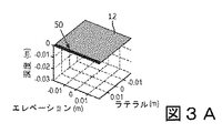
マイクロビームフォーマ14とシステムビームフォーマ22との間で、集束をこのように分割することの効果は、図3に示される遅延プロファイルによって説明される。図3Aは、図に網掛け表示される端の1×Nパッチ50を有する2Dアレイ12を示す。パッチ50は、横方向において1素子分の幅を有し、エレベーション方向においてアレイの全幅に沿って延在する。この例では、アレイの各パッチは、図3Cにおける遅延プロファイル70によって示されるように、エレベーション方向において集束される。したがって、パッチからの波面は、図3Cにおいて矢印71によって示されるように、アレイの中心から且つ当該中心と直交して延在する走査平面上でエレベーション方向において集束される。この集束は、この例では、プローブのマイクロビームフォーマによる各パッチの信号の遅延及び合計によって達成される。128×128素子アレイの例では、隣同士に向けられ、アレイの横(アジマス)方向に延在する128個のパッチから、128個の部分和信号がある。
The effect of this division of focusing between the microbeamformer 14 and the
パッチからの部分和信号は、プローブケーブルを介して、超音波システムメインフレームに結合され、ここで、この例では128個のパッチ信号を遅延させ、合計するシステムビームフォーマによって、ビーム形成処理が完了される。システムビームフォーマによる遅延及び合計は、図3Dにおける遅延プロファイル72によって示されるように、エコー信号の受信ビームを、横(アジマス)方向にステアリング及び集束させる。この例では、図の矢印73によって示されるように、左右対称の遅延プロファイルが、受信ビームをアレイの中心に垂直にステアリングする。 The partial sum signal from the patch is coupled to the ultrasonic system mainframe via a probe cable, where the beam forming process is completed by a system beamformer that delays and sums 128 patch signals in this example. Will be done. The delay and total by the system beamformer steer and focus the received beam of the echo signal laterally (azimuthally), as shown by the delay profile 72 in FIG. 3D. In this example, the symmetrical delay profile steers the received beam perpendicular to the center of the array, as indicated by arrow 73 in the figure.
図3Bに、複合遅延プロファイル74、即ち、マイクロビームフォーマによってもたらされるエレベーション方向の集束遅延とシステムビームフォーマによってもたらされる面内(アジマス)方向の集束遅延との組み合わせが示される。矢印75によって示されるように、結果として得られるビームは、エレベーション方向の集束遅延及び横(アジマス)方向の集束遅延の両方の左右対称の遅延プロファイル70及び72の結果、アレイの中心に直交してステアリング及び集束される。
FIG. 3B shows the
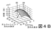
図4は、上記分割されたエレベーション方向の集束及びアジマス方向の集束の別の例を示し、今度は、システムビームフォーマによってもたらされる遅延によって、アジマス平面において左側にステアリングされるビームについての例である。図4Cは、矢印81によって示されるように、アレイの中心に直交して延在する平面に沿って集束される、前と同じエレベーション方向の集束遅延プロファイル80を示す。図4Dは、システムビームフォーマの遅延が左側に重み付けされ、矢印83によって示されるように、ビームを左側にステアリングする遅延プロファイル82によって示される。結果として、複合エレベーション及びアジマス方向の遅延プロファイル84は、ビームを、エレベーション方向では、アレイの中心に沿って向け、アジマス方向では、図4Bにおける矢印85によって示されるように、左側に向ける。
FIG. 4 shows another example of the above divided elevation and azimuth focusing, this time with an example of a beam steered to the left in the azimuth plane due to the delay caused by the system beamformer. be. FIG. 4C shows a focusing
図5は、本発明による2Dアレイ動作の別の実施態様を示す。この実施態様においても、M×Nアレイは、1×Nパッチにセグメント化され、更に、各1×Nパッチは、サブパッチに更にセグメント化される。その幾つかを、パッチ50について、90、94、98において示す。今度は、パッチ全体を、パッチ幅のエレベーション方向の平面において集束できることに加えて、素子の各サブパッチから、個々の集束を行うことができる。各1×Nパッチが128個の素子分の長さを有する128×128個の素子からなる2Dアレイの前述の例では、例えば各パッチは、それぞれ16個の素子からなる8個のサブパッチにセグメント化することができる。サブパッチは、特に3D撮像を行う場合に、表示フレームレートを更に向上させるように動作させられる。例えば、図5における2Dアレイの下のボリュメトリック領域内へと延在する3つの走査平面60、62及び64が示される。このような複数の平面を走査することができ、すべての平面からのエコーデータを使用して、アレイの下のボリュメトリック領域の3D画像が形成される。例えば64個のそのような平面を走査し、3D画像に必要な3Dデータが収集される。従来の走査では、これは、表示フレームレートを左右する64平面分のデータの取得時間が必要となる。しかし、図5は、単一の送信ビーム102に反応して、4つのそのような平面からのデータの走査線110、112、114及び116の同時取得を示す。これらの4つのマルチラインを形成するために必要な遅延は、マイクロビームフォーマによって適用されるか、又は、マルチラインは、システムビームフォーマによって適用される遅延によって形成されてもよい。したがって、このマルチライン取得によって、1つの平面を走査するのに通常必要な時間内で、4つの平面を走査することができ、表示フレームレートを4倍に増加させる。
FIG. 5 shows another embodiment of the 2D array operation according to the present invention. Also in this embodiment, the MxN array is segmented into 1xN patches, and each 1xN patch is further segmented into subpatches. Some of them are shown for
図6は、3D撮像用の表示フレームレートを更に増加させる本発明の別の実施態様を示す。この例では、受信マルチライン120は、エレベーション方向及びアジマス方向の両方において、単一の送信ビーム102の周りに形成される。図は、中心走査平面60bに形成される4つのマルチライン、1つの平行走査平面60aに形成される4つのマルチライン、及び、別の平行走査平面60cに形成される4つのマルチラインを示す。これは、従来のシングルライン走査に比べて、データ取得及びフレームレートを16倍に増加させる。マルチラインは、アジマス方向及びエレベーション方向の両方において延在するので、これらのマルチラインの形成のための遅延は、好適には、システムビームフォーマによって適用される。
FIG. 6 shows another embodiment of the present invention that further increases the display frame rate for 3D imaging. In this example, the receive
図7に、本発明に原理に従って構成された超音波システムの詳細なブロック図を示す。超音波プローブ10は、平面又はボリュメトリック領域全体に電子的にステアリング及び集束されたビームを送信し、各送信ビームに応えて1つ又は複数の受信ビームを受信する2次元アレイトランスデューサ12を含む。トランスデューサアレイの素子は、マイクロビームフォーマ(μBF)14に結合される。アレイの素子は、上記されたように、1×Nパッチ及びサブパッチで動作させられる。マイクロビームフォーマ14は、エレベーション方向における受信エコー信号の部分ビーム形成を行い、これにより、プローブ10とメインシステムとの間のケーブル16内の導体の数が減少される。適切な2次元アレイは、米国特許第6,419,633号(Robinson他)及び米国特許第6,368,281号(Solomon他)に説明されている。マイクロビームフォーマは、米国特許第5,997,479号(Savord他)及び第6,013,032号(Savord)に説明されている。アレイの送信ビーム特性は、アレイのアポダイゼーション絞り素子に、撮像のための関心領域を通る所望の方向において所望幅の集束ビームを放出させるビーム送信器42によって制御される。送信パルスは、送信/受信スイッチ18によって、ビーム送信器42からアレイの素子に結合される。送信ビームに応えてアレイ素子及びマイクロビームフォーマによって受信されるエコー信号は、マイクロビームフォーマにおける1×Nパッチ信号の遅延及び合計によってエレベーション方向において集束され、システムビームフォーマ22に結合される。システムビームフォーマ22において、マイクロビームフォーマからの部分ビーム形成されたエコー信号が、アジマス方向に(側方に)計算された遅延で遅延され、合計されて、送信ビームに応えて、完全にビーム形成された単一又は複数の受信ビームが形成される。この目的に適したビームフォーマは、Savordの上記第‘032号特許に説明されている。
FIG. 7 shows a detailed block diagram of an ultrasonic system configured according to the principles of the present invention. The
ビームフォーマ22によって形成された受信ビームは、フィルタリング及び直交変調といった機能を行う信号プロセッサ24aに結合される。処理された受信ビームのエコー信号は、ドップラープロセッサ28及び/又はBモードプロセッサ24に結合される。ドップラープロセッサ28は、エコー情報をドップラーパワー又は速度情報に処理する。Bモード撮像では、受信ビームエコーの包絡線が検出され、Bモードプロセッサ24によって、信号は、適切なダイナミックレンジにまで対数的に圧縮される。ボリュメトリック領域からのエコー信号は、3D画像プロセッサ32によって処理されて、3D画像データセットが形成される。3D画像データは、幾つかの表示法のために処理される。1つは、ボリュームの複数の2D平面を生成するやり方である。これは、米国特許第6,443,896号(Detmer)に説明されている。ボリュメトリック領域のそのような平面画像は、マルチプラナリフォーマッタ34によって生成される。ボリュームレンダラ36によって、3次元画像データは、遠近法による又は動的視差による3D表示を形成するようにレンダリングされてもよい。米国特許第5,720,291号(Schwartz)に説明されるように、Bモードであっても、ドップラーであっても、その両方であってもよい結果として得られる画像は、表示プロセッサ38に結合される。そこから、当該画像は、画像ディスプレイ40で表示される。ビームフォーマコントローラ26及び超音波システムの他の機能のユーザ制御は、ユーザインターフェース又は制御パネル20を介して提供される。
The received beam formed by the
なお、上記され、図1の例示的な超音波システムによって説明された様々な実施形態は、ハードウェア、ソフトウェア又はそれらの組み合わせで実現されてよい。様々な実施形態、及び/又は、例えばモジュール若しくはその中のコンポーネント及びコントローラであるコンポーネントも、1つ以上のコンピュータ又はマイクロプロセッサの一部として実現されてよい。コンピュータ又はプロセッサは、コンピュータデバイス、入力デバイス、表示ユニット及び例えばインターネットにアクセスするためのインターフェースを含む。コンピュータ又はプロセッサは、マイクロプロセッサを含んでもよい。マイクロプロセッサは、例えばPACSシステムにアクセスするために通信バスに接続されてよい。コンピュータ又はプロセッサは更に、メモリを含んでよい。メモリには、ランダムアクセスメモリ(RAM)及び読み出し専用メモリ(ROM)が含まれてよい。コンピュータ又はプロセッサは更に、ハードディスクドライブ、又は、フロッピー(登録商標)ディスクドライブ、光学ディスクドライブ、固体サムドライブ等といったリムーバブルストレージドライブであってよいストレージデバイスを含んでよい。ストレージデバイスは更に、コンピュータプログラム又は他の命令をコンピュータ又はプロセッサにロードするための他の同様の手段であってもよい。 It should be noted that the various embodiments described above and described by the exemplary ultrasonic system of FIG. 1 may be implemented in hardware, software or a combination thereof. Various embodiments and / or components, such as modules or components within them and controllers, may also be implemented as part of one or more computers or microprocessors. A computer or processor includes a computer device, an input device, a display unit and, for example, an interface for accessing the Internet. The computer or processor may include a microprocessor. The microprocessor may be connected to a communication bus, for example to access a PACS system. The computer or processor may further include memory. The memory may include a random access memory (RAM) and a read-only memory (ROM). The computer or processor may further include a hard disk drive or a storage device that may be a removable storage drive such as a floppy (registered trademark) disk drive, optical disk drive, solid thumb drive, and the like. The storage device may also be another similar means for loading a computer program or other instruction into the computer or processor.
本明細書において使用される場合、「コンピュータ」、「モジュール」又は「プロセッサ」との用語には、マイクロコントローラ、縮小命令セットコンピュータ(RISC)、ASIC、論理回路及び本明細書において説明される機能を実行可能である任意の他の回路又はプロセッサを使用するシステムを含む任意のプロセッサベース又はマイクロプロセッサベースのシステムが含まれる。上記例は例示に過ぎないので、これらの用語の定義及び/又は意味をいかようにも限定することを意図していない。 As used herein, the terms "computer," "module," or "processor" refer to microprocessors, reduced instruction set computers (RISCs), ASICs, logic circuits, and features as described herein. Includes any processor-based or microprocessor-based system, including systems that use any other circuit or processor capable of performing the above. The above examples are merely examples and are not intended to limit the definitions and / or meanings of these terms in any way.
コンピュータ又はプロセッサは、入力データを処理するために、1つ以上のストレージ要素に記憶される命令のセットを実行する。ストレージ要素は更に、必要に応じて、データ又は他の情報も記憶する。ストレージ要素は、処理マシン内の情報源又は物理的なメモリ要素の形であってよい。 A computer or processor executes a set of instructions stored in one or more storage elements to process input data. The storage element also stores data or other information as needed. The storage element may be in the form of a source of information or a physical memory element within the processing machine.
命令のセットには、本発明の様々な実施形態の方法及び処理といった特定の演算を行うように、コンピュータ又はプロセッサに処理マシンとして命令する様々なコマンドが含まれる。命令のセットは、ソフトウェアプログラムの形であってよい。ソフトウェアは、システムソフトウェア又はアプリケーションソフトウェアといった様々な形式であってよく、また、有形及び非一時的なコンピュータ可読媒体として具体化される。更に、ソフトウェアは、別箇のプログラム又はモジュールの集合体、より大きいプログラム内のプログラムモジュール又はプログラムモジュールの一部の形であってよい。ソフトウェアは更に、オブジェクト指向プログラミングの形のモジュラプログラミングを含んでもよい。処理マシンによる入力データの処理は、操作者のコマンドに応えて、前の処理の結果に応じて、又は、別の処理マシンによるリクエストに応えて行われる。 The set of instructions includes various commands that instruct a computer or processor as a processing machine to perform certain operations, such as the methods and processes of various embodiments of the present invention. The set of instructions may be in the form of a software program. The software may be in various forms, such as system software or application software, and may be embodied as tangible and non-transitory computer-readable media. In addition, the software may be in the form of another program or collection of modules, a program module within a larger program, or a portion of a program module. The software may also include modular programming in the form of object-oriented programming. The processing of the input data by the processing machine is performed in response to the command of the operator, according to the result of the previous processing, or in response to the request by another processing machine.
更に、以下の請求項における限定は、ミーンズ・プラス・ファンクション形式で記載されておらず、当該請求項の限定が、更なる構造のない機能の説明が続く「〜の手段(means for)」の表現を明示的に使用しない限り及び明示的に使用するまで、米国特許法第112条第6パラグラフに基づいて解釈されることを意図していない。
Furthermore, the limitations in the following claims are not described in a means plus function format, and the limitations of the claims are of "means for" followed by a description of a function without further structure. Unless and expressly used, it is not intended to be construed under
本発明の実施態様の代替変形例は、当業者には容易に想起されるであろう。上記されたように、パッチのN方向がアジマス方向に延在し、1×Nパッチがエレベーション方向において隣同士に並べられるように、1×Nパッチの向きを90°(又は任意の他の角度)だけ回転させてもよい。別の変形例では、マイクロビームフォーマが、アジマス方向に集束遅延を適用するように設定される一方で、システムビームフォーマが、エレベーション方向に集束遅延を適用する。例えばシステムは、物理スイッチ又はソフトキースイッチを用いて実現されてよく、これにより、ユーザは、1×NパッチのN方向の向きがエレベーション方向又はアジマス方向であるように選択することができ、マイクロビームフォーマ及びシステムビームフォーマによって適用される遅延は、選択された向きに合わせられる。このようなユーザ制御は、マトリクスアレイ用の従来のやり方で2Dアレイ及びビームフォーマを動作させるように標準的な2Dパッチを選択する第3の設定を有してもよい。 Alternative variations of embodiments of the present invention will be readily recalled to those skilled in the art. As mentioned above, the orientation of the 1xN patch is 90 ° (or any other) so that the N direction of the patch extends in the azimuth direction and the 1xN patches are next to each other in the elevation direction. It may be rotated by an angle). In another variant, the microbeamformer is configured to apply the focusing delay in the azimuth direction, while the system beamformer applies the focusing delay in the elevation direction. For example, the system may be implemented using physical switches or softkey switches, which allows the user to choose the N-direction orientation of the 1xN patch to be the elevation or azimuth orientation. The delay applied by the microbeamformer and system beamformer is tailored to the selected orientation. Such user control may have a third setting that selects standard 2D patches to operate the 2D array and beamformer in the conventional way for matrix arrays.
Claims (14)
2次元アレイトランスデューサの素子の1×Nパッチでターゲット領域を走査する前記2次元アレイトランスデューサを有する超音波プローブであって、前記1×NパッチのN方向は、エレベーション方向又はアジマス方向の一方に延在し、各1×Nパッチは、N個の素子の総数よりも少ない複数の素子を含むサブパッチに分割される、前記超音波プローブと、
前記超音波プローブ内にあり、前記2次元アレイトランスデューサの素子に結合され、各サブパッチから受信される信号に遅延を適用して、サブパッチ信号を、前記エレベーション方向又は前記アジマス方向の前記一方において集束させるマイクロビームフォーマと、
前記超音波プローブに結合され、集束された前記サブパッチ信号を受信し、前記サブパッチ信号に遅延を適用して、前記サブパッチ信号を、前記エレベーション方向又は前記アジマス方向の他方においてステアリング及び/又は集束させるシステムビームフォーマと、
前記マイクロビームフォーマ及び前記システムビームフォーマに結合され、ターゲット領域の走査を制御するようにユーザ制御に反応するビームフォーマコントローラと、
前記システムビームフォーマによってステアリング及び/又は集束された前記サブパッチ信号に反応して画像データを生成する画像プロセッサと、
前記画像プロセッサに結合され、前記ターゲット領域の2D又は3D画像を表示するディスプレイと、
を含む、超音波診断撮像システム。 An ultrasonic diagnostic imaging system that displays a 2D or 3D image, and the ultrasonic diagnostic imaging system is
An ultrasonic probe having the two-dimensional array transducer that scans the target region with a 1 × N patch of the element of the two-dimensional array transducer, and the N direction of the 1 × N patch is either the elevation direction or the azimuth direction. extends to each of 1 × N patch is divided into sub-patches comprising a plurality of elements smaller than the total number of N elements, and the ultrasonic probe,
Wherein is in the ultrasonic in the probe, coupled to elements of the two-dimensional array transducer focused, by applying a delay to signals received from each subpatch subpatch signal in said one of said elevation direction or the azimuth direction Microbeam transducer to let
Coupled to said ultrasonic probe, receives a focused the subpatch signal, by applying a delay to the sub-patches signal, said sub-patches signal to the steering and / or focusing on the other of said elevation direction or the azimuth direction System beam former and
A beamformer controller that is coupled to the microbeamformer and the system beamformer and reacts to user control to control scanning of the target area.
An image processor that generates image data in response to the subpatch signal steered and / or focused by the system beamformer.
A display coupled to the image processor to display a 2D or 3D image of the target area.
Ultrasound diagnostic imaging system, including.
前記システムビームフォーマは更に、前記エレベーション方向に集束される前記サブパッチ信号をデジタル的に遅延させるデジタルビームフォーマを含む、請求項7に記載の超音波診断撮像システム。 The microbeam former focuses the transmission signal and / or the reception signal of the subpatch in the elevation direction.
The system beamformer further, the said subpatches signal is focused in the elevation direction including digital beamformer to digitally delay, the ultrasonic diagnostic imaging system of claim 7.
Mは、前記アジマス方向又は前記エレベーション方向の一方に延在し、Nは、前記アジマス方向又は前記エレベーション方向の他方に延在する、請求項1に記載の超音波診断撮像システム。 Furthermore the two-dimensional array transducer, each row comprises elements of M columns including N elements,
M, said extending in one azimuth direction or the elevation direction, N is the extend to the other of the azimuth direction or the elevation direction, the ultrasonic diagnostic imaging system of Claim 1.
Applications Claiming Priority (3)
| Application Number | Priority Date | Filing Date | Title |
|---|---|---|---|
| US201662315225P | 2016-03-30 | 2016-03-30 | |
| US62/315,225 | 2016-03-30 | ||
| PCT/EP2017/057301 WO2017167742A1 (en) | 2016-03-30 | 2017-03-28 | Two dimensional ultrasonic array transducer with one dimensional patches |
Publications (3)
| Publication Number | Publication Date |
|---|---|
| JP2019509856A JP2019509856A (en) | 2019-04-11 |
| JP2019509856A5 JP2019509856A5 (en) | 2020-05-07 |
| JP6960938B2 true JP6960938B2 (en) | 2021-11-05 |
Family
ID=58448535
Family Applications (1)
| Application Number | Title | Priority Date | Filing Date |
|---|---|---|---|
| JP2018551376A Active JP6960938B2 (en) | 2016-03-30 | 2017-03-28 | 2D ultrasonic array transducer with 1D patch |
Country Status (5)
| Country | Link |
|---|---|
| US (1) | US11911218B2 (en) |
| EP (1) | EP3436842B1 (en) |
| JP (1) | JP6960938B2 (en) |
| CN (1) | CN108885258B (en) |
| WO (1) | WO2017167742A1 (en) |
Families Citing this family (4)
| Publication number | Priority date | Publication date | Assignee | Title |
|---|---|---|---|---|
| WO2018087584A1 (en) * | 2016-11-11 | 2018-05-17 | B-K Medical Aps | 3-d imaging and/or flow estimation with a row-column addressed 2-d transducer array |
| CN109828029B (en) * | 2019-03-28 | 2021-08-27 | 烟台中凯检测科技有限公司 | Ultrasonic phased array detection system and method based on original data |
| EP4331498A1 (en) | 2021-04-30 | 2024-03-06 | FUJIFILM Corporation | Ultrasonic diagnostic device and method for controlling ultrasonic diagnostic device |
| WO2022230379A1 (en) * | 2021-04-30 | 2022-11-03 | 富士フイルム株式会社 | Ultrasound diagnostic device and method for controlling ultrasound diagnostic device |
Family Cites Families (28)
| Publication number | Priority date | Publication date | Assignee | Title |
|---|---|---|---|---|
| US4173007A (en) | 1977-07-01 | 1979-10-30 | G. D. Searle & Co. | Dynamically variable electronic delay lines for real time ultrasonic imaging systems |
| JP2789234B2 (en) | 1989-10-02 | 1998-08-20 | 株式会社日立メディコ | Ultrasound diagnostic equipment |
| US5229933A (en) | 1989-11-28 | 1993-07-20 | Hewlett-Packard Company | 2-d phased array ultrasound imaging system with distributed phasing |
| US5720291A (en) | 1996-03-22 | 1998-02-24 | Advanced Technology Laboratories, Inc. | Three dimensional medical ultrasonic diagnostic image of tissue texture and vasculature |
| JPH09322896A (en) | 1996-06-05 | 1997-12-16 | Matsushita Electric Ind Co Ltd | Ultrasonograph |
| US6013032A (en) | 1998-03-13 | 2000-01-11 | Hewlett-Packard Company | Beamforming methods and apparatus for three-dimensional ultrasound imaging using two-dimensional transducer array |
| US5997479A (en) | 1998-05-28 | 1999-12-07 | Hewlett-Packard Company | Phased array acoustic systems with intra-group processors |
| US6102860A (en) | 1998-12-24 | 2000-08-15 | Agilent Technologies, Inc. | Ultrasound transducer for three-dimensional imaging |
| US6368281B1 (en) | 1999-07-30 | 2002-04-09 | Rodney J Solomon | Two-dimensional phased array ultrasound transducer with a convex environmental barrier |
| JP4879430B2 (en) | 1999-09-17 | 2012-02-22 | 株式会社日立メディコ | Ultrasonic probe and ultrasonic diagnostic apparatus using the same |
| US6443896B1 (en) | 2000-08-17 | 2002-09-03 | Koninklijke Philips Electronics N.V. | Method for creating multiplanar ultrasonic images of a three dimensional object |
| US6468216B1 (en) * | 2000-08-24 | 2002-10-22 | Kininklijke Philips Electronics N.V. | Ultrasonic diagnostic imaging of the coronary arteries |
| US6419633B1 (en) | 2000-09-15 | 2002-07-16 | Koninklijke Philips Electronics N.V. | 2D ultrasonic transducer array for two dimensional and three dimensional imaging |
| US7135809B2 (en) | 2001-06-27 | 2006-11-14 | Koninklijke Philips Electronics, N.V. | Ultrasound transducer |
| US6730033B2 (en) | 2002-05-16 | 2004-05-04 | Siemens Medical Systems, Inc. | Two dimensional array and methods for imaging in three dimensions |
| JP2007513672A (en) * | 2003-12-11 | 2007-05-31 | コーニンクレッカ フィリップス エレクトロニクス エヌ ヴィ | Stereoscopic ultrasound imaging system using a two-dimensional array transducer |
| JP2008514335A (en) * | 2004-09-30 | 2008-05-08 | コーニンクレッカ フィリップス エレクトロニクス エヌ ヴィ | Transducer structure for microbeam formation |
| JP5161773B2 (en) | 2005-08-05 | 2013-03-13 | コーニンクレッカ フィリップス エレクトロニクス エヌ ヴィ | Bent two-dimensional array transducer |
| JP5137832B2 (en) | 2005-08-05 | 2013-02-06 | コーニンクレッカ フィリップス エレクトロニクス エヌ ヴィ | Curved two-dimensional array ultrasonic transducer and method for volumetric imaging |
| US8465431B2 (en) | 2005-12-07 | 2013-06-18 | Siemens Medical Solutions Usa, Inc. | Multi-dimensional CMUT array with integrated beamformation |
| EP2019626B1 (en) | 2006-05-12 | 2015-09-02 | Koninklijke Philips Electronics, N.V. | Incoherent retrospective dynamic transmit focusing |
| US8202222B2 (en) * | 2006-10-27 | 2012-06-19 | Sonoscape, Inc. | Equal phase two-dimensional array probe |
| US8647279B2 (en) * | 2010-06-10 | 2014-02-11 | Siemens Medical Solutions Usa, Inc. | Volume mechanical transducer for medical diagnostic ultrasound |
| KR101303626B1 (en) * | 2011-01-06 | 2013-09-11 | 서강대학교산학협력단 | Diagnosis system for diagnosing subject, medical image system for providing diagnosis image of subject and method for displaying diagnosis image of subject |
| US9739875B2 (en) * | 2013-02-12 | 2017-08-22 | Urs-Us Medical Technology Inc. | Analog store digital read ultrasound beamforming system and method |
| JP2014168500A (en) * | 2013-03-01 | 2014-09-18 | Hitachi Aloka Medical Ltd | Ultrasonic diagnostic apparatus |
| KR20150068846A (en) * | 2013-12-12 | 2015-06-22 | 삼성전자주식회사 | Ultrasonic diagnostic apparatus and control method thereof |
| KR102025258B1 (en) | 2014-01-28 | 2019-09-27 | 알피니언메디칼시스템 주식회사 | Image synthesis method and apparatus using plane wave in transducer having sub-array |
-
2017
- 2017-03-28 EP EP17714192.6A patent/EP3436842B1/en active Active
- 2017-03-28 JP JP2018551376A patent/JP6960938B2/en active Active
- 2017-03-28 CN CN201780021508.1A patent/CN108885258B/en active Active
- 2017-03-28 US US16/088,288 patent/US11911218B2/en active Active
- 2017-03-28 WO PCT/EP2017/057301 patent/WO2017167742A1/en active Application Filing
Also Published As
| Publication number | Publication date |
|---|---|
| WO2017167742A1 (en) | 2017-10-05 |
| JP2019509856A (en) | 2019-04-11 |
| EP3436842B1 (en) | 2024-03-20 |
| EP3436842A1 (en) | 2019-02-06 |
| US20190083064A1 (en) | 2019-03-21 |
| US11911218B2 (en) | 2024-02-27 |
| CN108885258A (en) | 2018-11-23 |
| CN108885258B (en) | 2024-03-08 |
Similar Documents
| Publication | Publication Date | Title |
|---|---|---|
| EP1913419B1 (en) | Curved 2-d array ultrasound transducer and method for volumetric imaging | |
| US6537220B1 (en) | Ultrasound imaging with acquisition of imaging data in perpendicular scan planes | |
| JP6960938B2 (en) | 2D ultrasonic array transducer with 1D patch | |
| EP3376253A2 (en) | Ultrasound 3d imaging system | |
| JP4428477B2 (en) | Method and apparatus for rapid distributed calculation of time delay and apodization values for beamforming | |
| US20140155751A1 (en) | Method and system for element-by-element flexible subarray beamforming | |
| US11391838B2 (en) | Ultrasound transducer arrays with variable patch geometries | |
| WO2006134686A1 (en) | Ultrasonographic device | |
| EP2726903B1 (en) | Two dimensional ultrasonic diagnostic imaging system with two beamformer stages | |
| JP2001245884A (en) | Ultrasonic imaging apparatus | |
| JP2022502113A (en) | 3D ultrasound imaging with wide focused transmit beam at high display frame rate | |
| JP2005342194A (en) | Ultrasonic diagnostic apparatus | |
| KR19990045153A (en) | Ultrasonic probe manufacturing method, ultrasonic probe and ultrasonic imaging device | |
| US10304226B2 (en) | Ultrasound focal zone system and method | |
| WO2017168279A1 (en) | Two dimensional ultrasonic array transducer with one dimensional subpatches | |
| US20210219952A1 (en) | Ultrasonic imaging by sparse sampling and associated devices, systems, and methods | |
| JP2002165790A (en) | Ultrasonic imaging device | |
| CN114072063B (en) | Ultrasonic three-dimensional imaging method and device | |
| JP2000312676A (en) | Ultrasonic diagnostic system | |
| Kim et al. | Hybrid beamformation for volumetric ultrasound imaging scanners using 2-D array transducers |
Legal Events
| Date | Code | Title | Description |
|---|---|---|---|
| A521 | Request for written amendment filed |
Free format text: JAPANESE INTERMEDIATE CODE: A523 Effective date: 20200325 |
|
| A621 | Written request for application examination |
Free format text: JAPANESE INTERMEDIATE CODE: A621 Effective date: 20200325 |
|
| A977 | Report on retrieval |
Free format text: JAPANESE INTERMEDIATE CODE: A971007 Effective date: 20210120 |
|
| A131 | Notification of reasons for refusal |
Free format text: JAPANESE INTERMEDIATE CODE: A131 Effective date: 20210222 |
|
| TRDD | Decision of grant or rejection written | ||
| A01 | Written decision to grant a patent or to grant a registration (utility model) |
Free format text: JAPANESE INTERMEDIATE CODE: A01 Effective date: 20210913 |
|
| A61 | First payment of annual fees (during grant procedure) |
Free format text: JAPANESE INTERMEDIATE CODE: A61 Effective date: 20211012 |
|
| R150 | Certificate of patent or registration of utility model |
Ref document number: 6960938 Country of ref document: JP Free format text: JAPANESE INTERMEDIATE CODE: R150 |