JP7561542B2 - Product sales data processing device and program - Google Patents
Product sales data processing device and program Download PDFInfo
- Publication number
- JP7561542B2 JP7561542B2 JP2020141559A JP2020141559A JP7561542B2 JP 7561542 B2 JP7561542 B2 JP 7561542B2 JP 2020141559 A JP2020141559 A JP 2020141559A JP 2020141559 A JP2020141559 A JP 2020141559A JP 7561542 B2 JP7561542 B2 JP 7561542B2
- Authority
- JP
- Japan
- Prior art keywords
- battery
- data processing
- tablet terminal
- sales data
- product sales
- Prior art date
- Legal status (The legal status is an assumption and is not a legal conclusion. Google has not performed a legal analysis and makes no representation as to the accuracy of the status listed.)
- Active
Links
Images


Classifications
-
- G—PHYSICS
- G06—COMPUTING OR CALCULATING; COUNTING
- G06F—ELECTRIC DIGITAL DATA PROCESSING
- G06F1/00—Details not covered by groups G06F3/00 - G06F13/00 and G06F21/00
- G06F1/26—Power supply means, e.g. regulation thereof
- G06F1/263—Arrangements for using multiple switchable power supplies, e.g. battery and AC
-
- H—ELECTRICITY
- H02—GENERATION; CONVERSION OR DISTRIBUTION OF ELECTRIC POWER
- H02J—ELECTRIC POWER NETWORKS; CIRCUIT ARRANGEMENTS OR SYSTEMS FOR SUPPLYING OR DISTRIBUTING ELECTRIC POWER; SYSTEMS FOR STORING ELECTRIC ENERGY
- H02J7/00—Circuit arrangements for charging or discharging batteries or for supplying loads from batteries
- H02J7/855—Circuit arrangements for charging or discharging batteries or for supplying loads from batteries with circuits adapted for supplying loads from the battery
-
- G—PHYSICS
- G06—COMPUTING OR CALCULATING; COUNTING
- G06F—ELECTRIC DIGITAL DATA PROCESSING
- G06F3/00—Input arrangements for transferring data to be processed into a form capable of being handled by the computer; Output arrangements for transferring data from processing unit to output unit, e.g. interface arrangements
- G06F3/01—Input arrangements or combined input and output arrangements for interaction between user and computer
- G06F3/03—Arrangements for converting the position or the displacement of a member into a coded form
- G06F3/041—Digitisers, e.g. for touch screens or touch pads, characterised by the transducing means
-
- G—PHYSICS
- G06—COMPUTING OR CALCULATING; COUNTING
- G06F—ELECTRIC DIGITAL DATA PROCESSING
- G06F3/00—Input arrangements for transferring data to be processed into a form capable of being handled by the computer; Output arrangements for transferring data from processing unit to output unit, e.g. interface arrangements
- G06F3/14—Digital output to display device ; Cooperation and interconnection of the display device with other functional units
- G06F3/147—Digital output to display device ; Cooperation and interconnection of the display device with other functional units using display panels
-
- G—PHYSICS
- G06—COMPUTING OR CALCULATING; COUNTING
- G06Q—INFORMATION AND COMMUNICATION TECHNOLOGY [ICT] SPECIALLY ADAPTED FOR ADMINISTRATIVE, COMMERCIAL, FINANCIAL, MANAGERIAL OR SUPERVISORY PURPOSES; SYSTEMS OR METHODS SPECIALLY ADAPTED FOR ADMINISTRATIVE, COMMERCIAL, FINANCIAL, MANAGERIAL OR SUPERVISORY PURPOSES, NOT OTHERWISE PROVIDED FOR
- G06Q20/00—Payment architectures, schemes or protocols
- G06Q20/08—Payment architectures
- G06Q20/20—Point-of-sale [POS] network systems
- G06Q20/208—Input by product or record sensing, e.g. weighing or scanner processing
-
- G—PHYSICS
- G07—CHECKING-DEVICES
- G07G—REGISTERING THE RECEIPT OF CASH, VALUABLES, OR TOKENS
- G07G1/00—Cash registers
- G07G1/0036—Checkout procedures
- G07G1/0045—Checkout procedures with a code reader for reading of an identifying code of the article to be registered, e.g. barcode reader or radio-frequency identity [RFID] reader
- G07G1/0081—Checkout procedures with a code reader for reading of an identifying code of the article to be registered, e.g. barcode reader or radio-frequency identity [RFID] reader the reader being a portable scanner or data reader
-
- H—ELECTRICITY
- H01—ELECTRIC ELEMENTS
- H01M—PROCESSES OR MEANS, e.g. BATTERIES, FOR THE DIRECT CONVERSION OF CHEMICAL ENERGY INTO ELECTRICAL ENERGY
- H01M10/00—Secondary cells; Manufacture thereof
- H01M10/42—Methods or arrangements for servicing or maintenance of secondary cells or secondary half-cells
- H01M10/425—Structural combination with electronic components, e.g. electronic circuits integrated to the outside of the casing
-
- H—ELECTRICITY
- H02—GENERATION; CONVERSION OR DISTRIBUTION OF ELECTRIC POWER
- H02J—ELECTRIC POWER NETWORKS; CIRCUIT ARRANGEMENTS OR SYSTEMS FOR SUPPLYING OR DISTRIBUTING ELECTRIC POWER; SYSTEMS FOR STORING ELECTRIC ENERGY
- H02J7/00—Circuit arrangements for charging or discharging batteries or for supplying loads from batteries
- H02J7/50—Circuit arrangements for charging or discharging batteries or for supplying loads from batteries acting upon multiple batteries simultaneously or sequentially
- H02J7/585—Sequential battery discharge in systems with a plurality of batteries
-
- H—ELECTRICITY
- H02—GENERATION; CONVERSION OR DISTRIBUTION OF ELECTRIC POWER
- H02J—ELECTRIC POWER NETWORKS; CIRCUIT ARRANGEMENTS OR SYSTEMS FOR SUPPLYING OR DISTRIBUTING ELECTRIC POWER; SYSTEMS FOR STORING ELECTRIC ENERGY
- H02J7/00—Circuit arrangements for charging or discharging batteries or for supplying loads from batteries
- H02J7/80—Circuit arrangements for charging or discharging batteries or for supplying loads from batteries including monitoring or indicating arrangements
- H02J7/82—Control of state of charge [SOC]
-
- H—ELECTRICITY
- H02—GENERATION; CONVERSION OR DISTRIBUTION OF ELECTRIC POWER
- H02J—ELECTRIC POWER NETWORKS; CIRCUIT ARRANGEMENTS OR SYSTEMS FOR SUPPLYING OR DISTRIBUTING ELECTRIC POWER; SYSTEMS FOR STORING ELECTRIC ENERGY
- H02J7/00—Circuit arrangements for charging or discharging batteries or for supplying loads from batteries
- H02J7/90—Regulation of charging or discharging current or voltage
- H02J7/96—Regulation of charging or discharging current or voltage in response to battery voltage
-
- B—PERFORMING OPERATIONS; TRANSPORTING
- B62—LAND VEHICLES FOR TRAVELLING OTHERWISE THAN ON RAILS
- B62B—HAND-PROPELLED VEHICLES, e.g. HAND CARTS OR PERAMBULATORS; SLEDGES
- B62B3/00—Hand carts having more than one axis carrying transport wheels; Steering devices therefor; Equipment therefor
- B62B3/14—Hand carts having more than one axis carrying transport wheels; Steering devices therefor; Equipment therefor characterised by provisions for nesting or stacking, e.g. shopping trolleys
- B62B3/1408—Display devices mounted on it, e.g. advertisement displays
- B62B3/1424—Electronic display devices
-
- H—ELECTRICITY
- H01—ELECTRIC ELEMENTS
- H01M—PROCESSES OR MEANS, e.g. BATTERIES, FOR THE DIRECT CONVERSION OF CHEMICAL ENERGY INTO ELECTRICAL ENERGY
- H01M10/00—Secondary cells; Manufacture thereof
- H01M10/42—Methods or arrangements for servicing or maintenance of secondary cells or secondary half-cells
- H01M10/425—Structural combination with electronic components, e.g. electronic circuits integrated to the outside of the casing
- H01M2010/4271—Battery management systems including electronic circuits, e.g. control of current or voltage to keep battery in healthy state, cell balancing
-
- H—ELECTRICITY
- H01—ELECTRIC ELEMENTS
- H01M—PROCESSES OR MEANS, e.g. BATTERIES, FOR THE DIRECT CONVERSION OF CHEMICAL ENERGY INTO ELECTRICAL ENERGY
- H01M2220/00—Batteries for particular applications
- H01M2220/30—Batteries in portable systems, e.g. mobile phone, laptop
-
- Y—GENERAL TAGGING OF NEW TECHNOLOGICAL DEVELOPMENTS; GENERAL TAGGING OF CROSS-SECTIONAL TECHNOLOGIES SPANNING OVER SEVERAL SECTIONS OF THE IPC; TECHNICAL SUBJECTS COVERED BY FORMER USPC CROSS-REFERENCE ART COLLECTIONS [XRACs] AND DIGESTS
- Y02—TECHNOLOGIES OR APPLICATIONS FOR MITIGATION OR ADAPTATION AGAINST CLIMATE CHANGE
- Y02E—REDUCTION OF GREENHOUSE GAS [GHG] EMISSIONS, RELATED TO ENERGY GENERATION, TRANSMISSION OR DISTRIBUTION
- Y02E60/00—Enabling technologies; Technologies with a potential or indirect contribution to GHG emissions mitigation
- Y02E60/10—Energy storage using batteries
Landscapes
- Engineering & Computer Science (AREA)
- Theoretical Computer Science (AREA)
- Business, Economics & Management (AREA)
- Physics & Mathematics (AREA)
- General Physics & Mathematics (AREA)
- Power Engineering (AREA)
- General Engineering & Computer Science (AREA)
- Accounting & Taxation (AREA)
- Human Computer Interaction (AREA)
- Strategic Management (AREA)
- General Business, Economics & Management (AREA)
- Finance (AREA)
- Microelectronics & Electronic Packaging (AREA)
- Manufacturing & Machinery (AREA)
- Chemical & Material Sciences (AREA)
- Chemical Kinetics & Catalysis (AREA)
- Electrochemistry (AREA)
- General Chemical & Material Sciences (AREA)
- Charge And Discharge Circuits For Batteries Or The Like (AREA)
- Cash Registers Or Receiving Machines (AREA)
- Power Sources (AREA)
Description
本発明の実施の形態は、商品販売データ処理装置およびプログラムに関する。 An embodiment of the present invention relates to a product sales data processing device and a program.
近年、店舗で購入した商品の登録や決済を行うPOS(Point Of Sales)端末を、顧客が自ら操作可能とした、セルフレジやセミセルフレジが実用化している。さらに、ショッピングカートにPOS端末の機能を実装して、買い物をしながら商品の登録等を行うことが可能なカートPOSも提案されている。 In recent years, self-service and semi-self-service registers have become commonplace, allowing customers to operate point-of-sale (POS) terminals that register and pay for products purchased in stores. In addition, cart POS systems have been proposed, which implement POS terminal functions in shopping carts, allowing customers to register products while shopping.
例えばカートPOSでは、DC電源で駆動するタブレット端末、スキャナ、カードリーダ等の入出力機器を搭載している。そして、これらの入出力機器は、カートPOSに搭載されたバッテリから給電される。バッテリ容量には限界があるため、カートPOSには複数のバッテリを搭載して、給電中のバッテリ残量が減った場合には、即座に別のバッテリに繋ぎ替えを行うのが望ましい。また、今後、カートPOSには、カメラをはじめとするその他のデバイスも接続される可能性があるため、バッテリの消費電力は更に増加することが見込まれる。 For example, a cart POS is equipped with input/output devices such as a tablet terminal, scanner, and card reader that run on DC power. These input/output devices are powered by a battery installed in the cart POS. Because battery capacity is limited, it is desirable to install multiple batteries in the cart POS so that if the remaining charge of the current battery becomes low, the battery can be immediately switched to another battery. Furthermore, in the future, there is a possibility that other devices such as cameras will be connected to cart POS, so battery power consumption is expected to increase further.
このように複数のバッテリを搭載した装置として、例えば特許文献1に記載されたカートが知られている。 An example of such a device equipped with multiple batteries is the cart described in Patent Document 1.
しかしながら、特許文献1に記載されたカートでは、バッテリをどのような切替タイミングで切り替えるのかについて言及されていなかった。 However, the cart described in Patent Document 1 does not mention when the batteries should be switched.
本発明が解決しようとする課題は、給電中にバッテリの残量が減った場合に、適切なタイミングでバッテリの接続切替を自動的に行う商品販売データ処理装置およびプログラムを提供することである。 An object of the present invention is to provide a product sales data processing device and a program that automatically switches the battery connection at an appropriate timing when the remaining battery power decreases during power supply.
実施の形態の情報処理装置は、給電部と、接続切替部とを備える。給電部は、複数のバッテリのうちいずれかのバッテリから、当該バッテリと接続された、商品販売データ処理装置が備えるデバイスに給電を行う。接続切替部は、デバイスに接続されたバッテリの状態と、接続デバイス検出部が検出した、商品販売データ処理装置に接続されているデバイスの種類と、接続デバイス管理ファイルに登録されたデバイスの消費電力と、に基づいて、商品販売データ処理装置に接続されているデバイスを全て動作可能とするように、デバイスに給電を行うバッテリとその接続形態とを切り替える。 The information processing device according to the embodiment includes a power supply unit and a connection switching unit. The power supply unit supplies power from one of a plurality of batteries to a device included in the product sales data processing device and connected to the battery. The connection switching unit switches between the battery that supplies power to the device and its connection form so that all devices connected to the product sales data processing device can be operated based on the state of the battery connected to the device, the type of device connected to the product sales data processing device detected by the connected device detection unit, and the power consumption of the device registered in the connected device management file.
(第1の実施の形態)
本発明の第1の実施の形態であるカートPOS10aについて説明する。
(First embodiment)
A
(カートPOSの全体構成の説明)
図1は、第1の実施の形態のカートPOSの概略斜視図である。
(Explanation of the Overall Configuration of Cart POS)
FIG. 1 is a schematic perspective view of a cart POS according to a first embodiment.
カートPOS10aは、客が買い物を行う際に、店内を移動させながら、購入する商品を収納するショッピングカート12に、POS端末が持つ、一部または全ての機能を備えたものである。カートPOS10aは、タブレット端末14aと、スキャナ30cと、カードリーダ30dと、バッテリ40とを備える。なお、タブレット端末14は、本発明における情報処理装置の一例である。また、本実施の形態では、タブレット端末14aは、客が購入する商品を登録する機能のみを備えているものとして説明する。
The cart POS 10a is a
ショッピングカート12は、収納部12aと、キャスタ部12bと、ハンドル部12cとを備える。収納部12aは、上面が開口した籠状の部材であって、客が購入する商品が収納される。キャスタ部12bは、ショッピングカート12の底面に備えられて、前後左右に移動可能な複数の車輪を備える。ハンドル部12cは、客がショッピングカート12を移動させる際に把持する部材である。
The
タブレット端末14aは、客が購入する商品の商品情報を取得して、商品登録処理を行う。タブレット端末14aは、例えばLCD(Liquid Crystal Display)で構成されたモニタ30aと、モニタ30aの表示面に積層されたタッチパネル30bとを備える。モニタ30aは、タブレット端末14aが出力する情報を表示する表示デバイスである。タッチパネル30bは、客がタブレット端末14aに対して操作情報を入力する操作デバイスである。
The
スキャナ30cは、客が購入する商品に付されたバーコード等のコードシンボルの内容を読み取る。コードシンボルには、商品を一意に特定する商品コードが登録されている。スキャナ30cは、商品に照明光を照射するLED(Light Emitting Diode)と、商品に付されたコードシンボルで反射した光を受光するCCD(Charge Coupled Device)やCMOS(Complementary Metal Oxide Semiconductor)等の受光素子と、受光素子が受光した光をデコードしてデジタル信号に変換するデコーダ(いずれも非図示)等を内蔵する。なお、スキャナ30cの一面には、LEDからの光を出射し、コードシンボルを読み取らせるための読取窓が設けられている。客は、収納部12aに商品を収納する際に、読取窓に、商品に付されたコードシンボルを翳すことによって、スキャナ30cにコードシンボルを読み取らせる。なお、カートPOS10aは、スキャナ30cの代わりに、客が自ら把持して、商品に付されたコードシンボルに近接させることによって、当該コードシンボルを読み取るハンドスキャナを備えてもよい。
The
タブレット端末14aは、スキャナ30cが読み取ったコードシンボルの内容、即ち商品コードをデコードする。そして、客が購入する商品を一意に特定するとともに、当該商品を登録する。
The
カードリーダ30dは、客が所持する店舗の会員カードをスキャンすることによって、当該会員カードに記憶された会員情報等の情報を読み取る。読み取った会員情報は、例えば、商品の購入金額に応じてポイントを付与する際などに利用される。
The
バッテリ40は、タブレット端末14aと、スキャナ30cと、カードリーダ30dとに電力を供給(給電)する。バッテリ40は、重量物であるため、できるだけ下方、例えば、収納部12aの下方等に設置される。バッテリ40は、複数のバッテリ40a,40b,…,40nを備える(図2参照)。そして、十分な給電能力を持つバッテリが選択されて、前記各部位と接続され、給電が行われる。詳しくは後述する。なお、バッテリ40は、例えばリチウムイオン電池、ニッケル水素電池等の充電可能な電池(二次電池)である。
The
(タブレット端末のハードウエア構成の説明)
次に、図2を用いて、タブレット端末14aのハードウエア構成を説明する。図2は、第1の実施の形態のタブレット端末のハードウエア構成の一例を示すハードウエアブロック図である。
(Explanation of the hardware configuration of the tablet device)
Next, the hardware configuration of the
タブレット端末14aは、制御部20aと、記憶部24と、入出力コントローラ26と、無線通信インタフェース28とを備える。
The
制御部20aは、CPU(Central Processing Unit)21と、ROM22と、RAM23とを備えた一般的なコンピュータの構成を有する。CPU21は、ROM22や後述する記憶部24に記憶された各種プログラムやデータファイル等を読み出して、RAM23に展開する。CPU21は、RAM23に展開された各種プログラムやデータファイル等に従って動作して、タブレット端末14aの全体の制御を司る。
The
制御部20aは、内部バス29を介して、記憶部24と、補助バッテリ25と、入出力コントローラ26と、バッテリセレクタ27aと、無線通信インタフェース28と、それぞれ接続される。
The
記憶部24は、電源を切っても記憶情報を保持する。記憶部24は、例えばHDD(Hard Disk Drive)である。また、HDDの代わりに、フラッシュメモリ等の不揮発性メモリを備えてもよい。記憶部24は、制御プログラムP1を含むプログラム等を記憶する。制御プログラムP1は、タブレット端末14aが備える機能を発揮させるためのプログラムである。
The memory unit 24 retains stored information even when the power is turned off. The memory unit 24 is, for example, a hard disk drive (HDD). Instead of a HDD, a non-volatile memory such as a flash memory may be provided. The memory unit 24 stores programs including the control program P1. The control program P1 is a program for implementing the functions of the
なお、制御プログラムP1は、ROM22に予め組み込まれて提供されてもよい。また、制御プログラムP1は、制御部20aにインストール可能な形式又は実行可能な形式のファイルで、CD-ROM、フレキシブルディスク(FD)、CD-R、DVD(Digital Versatile Disc)等のコンピュータで読み取り可能な記録媒体に記録して提供するように構成してもよい。さらに、制御プログラムP1を、インターネット等のネットワークに接続されたコンピュータ上に格納し、ネットワーク経由でダウンロードさせることにより提供するように構成してもよい。また、制御プログラムP1を、インターネット等のネットワーク経由で提供または配布するように構成してもよい。
The control program P1 may be provided in advance by being incorporated in the
記憶部24は、更に、商品マスタMと、商品登録ファイルRと、バッテリ状態監視ファイルBと、接続デバイス管理ファイルDとを記憶する。 The memory unit 24 further stores a product master M, a product registration file R, a battery status monitoring file B, and a connected device management file D.
商品マスタMは、商品コードに対応させて、商品の名称、単価等の商品情報を格納したマスタファイルである。なお、商品マスタMは、タブレット端末14aと、不図示の店舗サーバとが通信を行うことによって、逐次更新される。
The product master M is a master file that stores product information such as product names and unit prices in correspondence with product codes. The product master M is updated sequentially through communication between the
商品登録ファイルRは、客によって登録された商品情報を格納したファイルである。 Product registration file R is a file that stores product information registered by customers.
バッテリ状態監視ファイルBは、各バッテリ40a,40b,…,40nの充電状態を記憶したファイルである。充電状態は、例えば、バッテリセレクタ27aが定期的に測定した、各バッテリ40a,40b,…,40nの出力電圧を記憶する。なお、バッテリ状態監視ファイルBは、未接続のバッテリも含めた全てのバッテリ40の出力電圧を記憶してもよいし、その時点で接続されて給電を行っているバッテリ40のみの出力電圧を記憶してもよい。
The battery status monitoring file B is a file that stores the charging state of each
接続デバイス管理ファイルDは、バッテリ40から給電されて動作する機器の一覧を格納したファイルである。例えば、図2の構成の場合、接続デバイス管理ファイルDには、タブレット端末14aと、モニタ30aと、タッチパネル30bと、スキャナ30cと、カードリーダ30dと、バッテリセレクタ27aとが登録される。なお、これらの入出力機器、即ち、モニタ30aと、タッチパネル30bと、スキャナ30cと、カードリーダ30dとは、本開示におけるデバイスの一例である。なお、これらのデバイスを総称して、以降、デバイス30と呼ぶ場合がある。
The connected device management file D is a file that stores a list of devices that operate using power supplied from the
また、接続デバイス管理ファイルDには、各デバイス30と関連付けて、当該デバイスの消費電力が登録されている。タブレット端末14aは、接続デバイス管理ファイルDに登録された、デバイスの消費電力と、バッテリ状態監視ファイルBが有する、各バッテリの充電状態とに基づいて、デバイス30に給電するバッテリ40を選択する。具体的には、タブレット端末14aは、当該タブレット端末14aにどのバッテリを接続すれば、全てのデバイスが動作可能であるか、また、どのデバイスにどのバッテリを接続すれば、全てのデバイスが動作可能であるか等を判断する。
The connected device management file D also registers the power consumption of each
補助バッテリ25は、バッテリ40が未接続の場合に、タブレット端末14a、および当該タブレット端末14aに接続されたデバイス30を動作させる予備バッテリである。補助バッテリ25は、タブレット端末14aにバッテリ40が接続されている場合には、当該バッテリ40によって常に充電される状態になっており、満充電の状態を維持する。そして、バッテリ40から給電が行われない場合に、タブレット端末14aおよびデバイス30に給電を行う。
The
入出力コントローラ26は、制御部20aと、入出力機器であるモニタ30aと、タッチパネル30bと、スキャナ30cと、カードリーダ30dとを接続する。モニタ30aと、タッチパネル30bと、スキャナ30cと、カードリーダ30dの機能は、前記した通りである。
The input/
なお、タブレット端末14aには、当該タブレット端末14aの機能を増強するために、前記した以外のデバイスが接続される場合がある。例えば、カメラ、重量センサ等(いずれも非図示)である。カメラは、例えば、客が収納部12aに収納する商品を撮像する。タブレット端末14aは、撮像した画像に基づいて商品を識別する。即ち、カメラはスキャナ30cの代替として用いられる。また、重量センサは、収納部12aに収納された商品の重量を計測する。重量センサによって計測された商品の重量は、例えば、客の不正防止のために用いられる。
Note that devices other than those mentioned above may be connected to the
このように、接続されるデバイスの数が増加すると、バッテリ40の消費量が増加する。したがって、バッテリ40を、1日の営業時間に亘って無充電で使用することが難しくなる場合がある。そのため、営業時間中であっても、バッテリ40の接続を切り替えざるを得ない状況が発生する。
In this way, as the number of connected devices increases, the consumption of the
バッテリセレクタ27aは、複数のバッテリ40(40a,40b,…,40n)の中から、タブレット端末14aと、当該タブレット端末14aに接続されたデバイス30に給電を行うバッテリを選択する。
The
バッテリセレクタ27aの構造は問わないが、例えば、接続制御信号の入力に応じたリレーを動作させることによって、複数の入力端子と複数の出力端子との接続を変更するものであればよい。また、バッテリセレクタ27aは、例えばFETのスイッチング動作を用いて、複数の入力端子と複数の出力端子との接続を変更するものであってもよい。なお、バッテリセレクタ27a自身も、バッテリ40からの給電によって動作する。
The structure of the
無線通信インタフェース28は、タブレット端末14aと非図示の会計機および店舗サーバと無線通信を行う。
The wireless communication interface 28 performs wireless communication between the
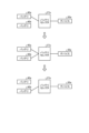
(バッテリの接続形態の説明)
次に、図3を用いて、バッテリ40とデバイス30との接続形態を説明する。図3は、バッテリとデバイスとの接続形態の一例を示す図である。
(Description of Battery Connection)
Next, a connection between the
図3(a)に示すように、1つのバッテリと1つのデバイスとを、バッテリセレクタ27aを介して、1対1で接続してもよい。例えば、接続する全てのデバイスが消費電力の大きいデバイスである場合には、各デバイスを専用のバッテリと接続するのが望ましい。この場合、バッテリセレクタ27aは、複数のバッテリ40と複数のデバイス30とを、任意に1対1で接続可能とすればよい。
As shown in FIG. 3(a), one battery and one device may be connected on a one-to-one basis via the
また、図3(b)に示すように、複数のバッテリと1つのデバイスとを、バッテリセレクタ27aを介して接続してもよい。例えば、消費電力が大きいデバイスや稼働時間が長いデバイスを接続する場合には、このような接続形態とするのが望ましい。この場合、バッテリセレクタ27aは、複数のバッテリ40と1つのデバイス30とを、任意に多対1で接続可能とすればよい。
Also, as shown in FIG. 3(b), multiple batteries and one device may be connected via the
また、図3(c)に示すように、バッテリから一つのデバイスに給電した後で、当該デバイスから他のデバイスに直列に給電してもよい。例えば、図3(c)において、バッテリ40aから最初に給電されるデバイス30aに対して、他の接続デバイスの消費電力が小さい場合には、このような接続形態とするのが望ましい。なお、給電されたデバイスから他のデバイスへの給電は、例えばUSB(Universal Serial Bus)ケーブルを用いて行うことができる。この場合、バッテリセレクタ27aは、1つのバッテリ40と1つのデバイス30とを、任意に1対1で接続可能とすればよい。
Also, as shown in FIG. 3(c), after one device is powered from the battery, that device may supply power in series to other devices. For example, in FIG. 3(c), this type of connection is desirable when the power consumption of the other connected devices is smaller than that of the
また、図3(d)に示すように、バッテリから一つのデバイスに給電した後で、当該デバイスから他のデバイスに並列に給電してもよい。例えば、図3(d)において、バッテリ40aから最初に給電されるデバイス30aは、デバイス30bおよびデバイス30cに対して、同時に電力供給を行う。
Also, as shown in FIG. 3(d), after one device is powered from the battery, the device may supply power in parallel to other devices. For example, in FIG. 3(d),
(バッテリの接続切替方法の説明)
次に、図4を用いて、バッテリ40aをバッテリ40bに切り替える際の接続切替方法を説明する。図4は、バッテリの接続を切り替える方法の一例を示す図である。
(Explanation of how to switch battery connections)
Next, a connection switching method for switching the
本実施の形態のタブレット端末14aは、バッテリの接続を切り替える際に、バッテリ40とデバイス30との接続が途切れることがない接続切替機能を備える。
The
例えば、図4の上段に示す接続状態、即ち、バッテリ40aとデバイス30aとがバッテリセレクタ27aを介して接続されているとする。そして、このとき、バッテリ40aをバッテリ40bに繋ぎ替えるものとする。
For example, assume that the connection state shown in the upper part of FIG. 4 is such that
このとき、タブレット端末14aは、バッテリセレクタ27aを制御することによって、一時的に、バッテリ40aとバッテリ40bとが、同時にデバイス30aに接続された状態を作る(図4の中段)。
At this time, the
そして、この後、タブレット端末14aは、バッテリセレクタ27aを制御することによって、バッテリ40aとデバイス30aとの接続を切断する(図4の下段)。このとき、バッテリ40bとデバイス30aとは接続された状態になっているため、バッテリからデバイスへの給電が途切れることはない。
Then, the
なお、タブレット端末14aは、前記した補助バッテリ25を備えている。したがって、バッテリの接続を切断して、別のバッテリに繋ぎ変えても、タブレット端末14a、および当該タブレット端末14aに接続したデバイス30の動作が停止することはない。しかし、本実施の形態のタブレット端末14aは、図4に示す接続切替方式も備えるため、必要に応じた接続切替方式を選択して実行することができる。例えば、消費電力が大きいデバイス30が接続されている場合には、バッテリ40の接続を切り替える際に補助バッテリ25に負担がかかるため、補助バッテリ25を介さずにバッテリ40を切り替えるのが望ましい。
The
(タブレット端末の機能構成の説明)
次に、図5を用いて、タブレット端末14aの機能構成を説明する。図5は、第1の実施の形態のタブレット端末の機能構成の一例を示す機能ブロック図である。
(Explanation of the functional configuration of a tablet device)
Next, the functional configuration of the
タブレット端末14aの制御部20a(図2参照)は、制御プログラムP1をRAM23に展開して動作させることによって、図5に示すバッテリ電圧検出部50と、バッテリ電圧判定部52と、動作状態取得部54と、接続デバイス検出部56と、バッテリ接続切替部58と、給電部60と、動作制御部62とを機能部として実現する。
The
バッテリ電圧検出部50は、タブレット端末14aおよびデバイス30に接続されている全てのバッテリ40の出力電圧eを検出する。バッテリ電圧検出部50は、例えばバッテリセレクタ27aの入力端子または出力端子において計測されたバッテリ40の出力電圧eを取得する。
The battery
バッテリ電圧判定部52は、バッテリ電圧検出部50が取得したバッテリ40の出力電圧eが、電圧閾値eth以下であるかを判定する。電圧閾値ethは、例えば、バッテリ40が完全に充電された状態における出力電圧eが10%低下した電圧に設定される。
The battery
動作状態取得部54は、タブレット端末14aの動作状態を取得する。例えば、動作状態取得部54は、タブレット端末14aが、少なくともスタンバイ状態にあるか否かを取得する。スタンバイ状態とは、タブレット端末14a、およびタブレット端末14aに接続された全てのデバイス30が動作していない状態のことである。例えば、カートPOS10aが店舗のカート置場に置かれている状態や、カートPOS10aが、客に押されて単に移動している状態や、タブレット端末14aが長時間操作を受け付けていないタイムアウト状態等が、スタンバイ状態の一例である。
The operation
接続デバイス検出部56は、タブレット端末14aに接続されているデバイス30を検出する。
The connected
バッテリ接続切替部58は、デバイス30に接続されたバッテリ40の状態に基づいて、接続切替後のバッテリ40の接続形態を決定する。また、バッテリ接続切替部58は、決定した接続形態になるように、バッテリ40とデバイス30との接続を切り替える。なお、バッテリ接続切替部58は、本開示における接続切替部の一例である。
The battery
ここで、バッテリ接続切替部58は、タブレット端末14aがスタンバイ状態である場合に、バッテリ40の接続を切り替えるのが望ましい。これは、例えば、消費電力が大きいデバイス30が接続されている場合に、当該デバイス30が動作している状態でバッテリ40の接続を切り替えると、補助バッテリ25に負担がかかって、デバイス30の動作が不安定になる恐れがあるためである。なお、バッテリ電圧判定部52が、バッテリ40の出力電圧eが低下して電圧閾値eth以下になったと判定した場合であっても、タブレット端末14aおよび接続されたデバイス30が即座に動作を停止する訳ではないため、タブレット端末14aが実行中の処理を完了してスタンバイ状態になった後で、バッテリ40の接続を切り替えても、タブレット端末14aの動作に支障をきたすことはない。
Here, it is preferable that the battery
給電部60は、複数のバッテリ40a,40b,…,40nのうちいずれかのバッテリから、当該バッテリと接続されたデバイス30に給電を行う。
The
動作制御部62は、タブレット端末14aの動作全体を制御する。
The
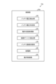
(タブレット端末が行う処理の流れの説明)
次に、図6を用いて、タブレット端末14aが行う処理の流れを説明する。図6は、第1の実施の形態のタブレット端末が行うバッテリ切替処理の流れの一例を示すフローチャートである。
(Explanation of the process flow performed by tablet devices)
Next, the flow of processing performed by the
接続デバイス検出部56は、タブレット端末14aに接続されているデバイス30を検出する(ステップS11)。
The connected
バッテリ電圧検出部50は、タブレット端末14aおよびデバイス30に給電している全てのバッテリ40の出力電圧eを検出する(ステップS12)。
The battery
バッテリ電圧判定部52は、バッテリ電圧検出部50が取得したバッテリ40の出力電圧eが、電圧閾値eth以下であるかを判定する(ステップS13)。バッテリ40の出力電圧eが、電圧閾値eth以下であると判定される(ステップS13:Yes)とステップS14に進む。一方、バッテリ40の出力電圧eが、電圧閾値eth以下であると判定されない(ステップS13:No)とステップS12に戻る。
The battery
ステップS13においてYesと判定されると、動作状態取得部54は、タブレット端末14aの動作状態を取得して、タブレット端末14aがスタンバイ状態であるかを判定する(ステップS14)。タブレット端末14aがスタンバイ状態であると判定される(ステップS14:Yes)とステップS15に進む。一方、タブレット端末14aがスタンバイ状態であると判定されない(ステップS14:No)とステップS14の判定を繰り返す。
If the answer to step S13 is Yes, the operation
ステップS14においてYesと判定されると、バッテリ接続切替部58は、接続切替後の、バッテリ40とデバイス30との接続形態を決定する(ステップS15)。具体的には、バッテリ接続切替部58は、未接続のバッテリ40の中から、出力電圧eが電圧閾値ethを超えるバッテリ40を選択する。そして、選択されたバッテリ40から給電するデバイス30を決定する。
If the answer in step S14 is Yes, the battery
そして、バッテリ接続切替部58は、ステップS15において決定した接続状態になるように、バッテリ40とデバイス30との接続を切り替える(ステップS16)。
Then, the battery
給電部60は、新たに接続されたバッテリ40から、タブレット端末14aおよびデバイス30に対して給電を行う(ステップS17)。
The
動作制御部62は、タブレット端末14aの電源が切断されたかを判定する(ステップS18)。タブレット端末14aの電源が切断されたと判定される(ステップS18:Yes)と、タブレット端末14aは、図6の処理を終了する。一方、タブレット端末14aの電源が切断されたと判定されない(ステップS18:No)と、ステップS12に戻る。
The
なお、本実施の形態において、タブレット端末14aは、客が購入する商品の登録処理を行うものとして説明したが、タブレット端末14aは、登録処理の後で、更に、登録された商品の決済を行う決済処理を行ってもよい。
In this embodiment, the
以上説明したように、第1の実施の形態のタブレット端末14a(情報処理装置)において、バッテリ接続切替部58(接続切替部)は、デバイス30に接続されたバッテリ40の状態に基づいて、当該デバイス30に給電を行うバッテリ40を切り替える。そして、給電部60は、バッテリ接続切替部58によって接続が切り替えられたバッテリ40からデバイス30に給電を行う。したがって、給電中にバッテリの残量が減った場合に、適切なタイミングでバッテリの接続切替を自動的に行うことができる。
As described above, in the
また、第1の実施の形態のタブレット端末14a(情報処理装置)において、バッテリ接続切替部58(接続切替部)は、デバイス30に接続されたバッテリ40の出力電圧eが、電圧閾値ethを下回ったことを条件として、デバイス30に給電を行うバッテリ40を切り替える。したがって、バッテリの接続切替を行うタイミングを簡便に決定することができる。
In addition, in the
また、第1の実施の形態のタブレット端末14a(情報処理装置)において、バッテリ接続切替部58(接続切替部)は、接続されるデバイス30の消費電力に基づいて、デバイス30毎に異なるバッテリ40から給電を行うか、複数のデバイス30に同じバッテリ40から給電を行うかを選択する。したがって、接続されているデバイス30の状態に応じて、バッテリ40の適切な接続形態を決定することができる。
In addition, in the
また、第1の実施の形態のタブレット端末14a(情報処理装置)において、バッテリ接続切替部58(接続切替部)は、タブレット端末14aの動作状態に基づいて、バッテリ40の接続切替を行う。したがって、タブレット端末14aがスタンバイ状態になるのを待って、バッテリ40の接続切替を行うことができる。これにより、例えば、消費電力が大きいデバイス30が接続されている場合に、デバイス30が動作中にバッテリ40の接続切替を行うことによって、補助バッテリ25に負担がかかるのを防止することができる。
In addition, in the
(第2の実施の形態)
次に、本発明の第1の実施の形態であるカートPOS10b(非図示)について説明する。カートPOS10bは、カートPOS10aが備えるタブレット端末14aの代わりに、タブレット端末14b(非図示)を備える。カートPOS10bの外観は、カートPOS10aと同じである。
Second Embodiment
Next, a
タブレット端末14bは、第1の実施の形態で説明したタブレット端末14aと同じ機能を備えるが、バッテリ40の残量を判定する構成のみが異なる。
The tablet terminal 14b has the same functions as the
タブレット端末14bのハードウエア構成は、タブレット端末14aのハードウエア構成(図2参照)とほぼ等しい。即ち、タブレット端末14bは、タブレット端末14aが備える制御部20aの代わりに制御部20b(非図示)を備える。また、記憶部24は、制御プログラムP1の代わりに制御プログラムP2(非図示)を備える。
The hardware configuration of tablet terminal 14b is substantially the same as the hardware configuration of
(タブレット端末の機能構成の説明)
図7を用いて、タブレット端末14bの機能構成を説明する。図7は、第2の実施の形態のタブレット端末の機能構成の一例を示す機能ブロック図である。
(Explanation of the functional configuration of a tablet device)
The functional configuration of the tablet terminal 14b will be described with reference to Fig. 7. Fig. 7 is a functional block diagram showing an example of the functional configuration of the tablet terminal according to the second embodiment.
タブレット端末14bの制御部20b(非図示)は、制御プログラムP2(非図示)をRAM23に展開して動作させることによって、図7に示す電流検出部64と、消費電力積算部66と、バッテリ残量判定部68と、動作状態取得部54と、接続デバイス検出部56と、バッテリ接続切替部58と、給電部60と、動作制御部62とを機能部として実現する。
The control unit 20b (not shown) of the tablet terminal 14b deploys and operates a control program P2 (not shown) in the RAM 23, thereby realizing as functional units the
電流検出部64は、デバイス30に給電中のバッテリ40に流れる電流を検出する。具体的には、電流検出部64は、例えば、バッテリセレクタ27aの出力端に流れる電流iを検出する。
The
消費電力積算部66は、デバイス30に給電中のバッテリ40の消費電力Pの積算値を算出する。具体的には、消費電力積算部66は、電流検出部64が検出した電流iに基づいて算出される、デバイス30の消費電力Pを積算する。
The power consumption integrator 66 calculates an integrated value of the power consumption P of the
例えば、バッテリ40が抵抗値rのデバイス30に接続されている場合、デバイス30の消費電力Pは、式(1)で算出される。
For example, when a

バッテリ残量判定部68は、バッテリ40の初期容量Cと、消費電力積算部66が積算したバッテリ40の消費電力Pとに基づくバッテリ40の残量、即ち、差分値(C-P)の値が、所定の残量閾値Cthを下回ったかを判定する。バッテリ40の初期容量Cは、フル充電されたバッテリ40の容量を表す。なお、各バッテリ40の初期容量Cと、式(1)で算出された消費電力Pの積算値は、バッテリ状態監視ファイルBに記憶される。なお、バッテリ40がフル充電されたタイミングで、バッテリ状態監視ファイルBに記憶された当該バッテリ40の消費電力Pの積算値は、0にリセットされる。
The battery remaining capacity determination unit 68 determines whether the remaining capacity of the
動作状態取得部54と、接続デバイス検出部56と、バッテリ接続切替部58と、給電部60と、動作制御部62との機能は、タブレット端末14aが備える各部位の機能と同じであるため、説明は省略する。
The functions of the operation
(タブレット端末が行う処理の流れの説明)
次に、図8を用いて、タブレット端末14bが行う処理の流れを説明する。図8は、第2の実施の形態のタブレット端末が行うバッテリ切替処理の流れの一例を示すフローチャートである。
(Explanation of the process flow performed by tablet devices)
Next, the flow of processing performed by the tablet terminal 14b will be described with reference to Fig. 8. Fig. 8 is a flowchart showing an example of the flow of battery switching processing performed by the tablet terminal according to the second embodiment.
接続デバイス検出部56は、タブレット端末14bに接続されているデバイス30を検出する(ステップS21)。
The connected
電流検出部64は、デバイス30に給電中のバッテリ40に流れる電流を検出する(ステップS22)。
The
消費電力積算部66は、デバイス30に給電中のバッテリ40の消費電力Pの積算値を算出する(ステップS23)。具体的には、消費電力積算部66は、式(1)によって、消費電力Pの積算値を算出する。
The power consumption integrator 66 calculates the integrated value of the power consumption P of the
バッテリ残量判定部68は、バッテリ40の初期容量Cから、消費電力積算部66が積算したバッテリ40の消費電力Pの積算値を差し引いた差分値(C-P)が、残量閾値Cth以下であるかを判定する(ステップS24)。差分値(C-P)が、残量閾値Cth以下であると判定される(ステップS24:Yes)とステップS25に進む。一方、差分値(C-P)が、残量閾値Cth以下であると判定されない(ステップS24:No)とステップS22に戻る。
The battery remaining capacity determination unit 68 determines whether the difference value (C-P) obtained by subtracting the integrated value of the power consumption P of the
ステップS24においてYesと判定されると、動作状態取得部54は、タブレット端末14bの動作状態を取得して、タブレット端末14bがスタンバイ状態であるかを判定する(ステップS25)。タブレット端末14bがスタンバイ状態であると判定される(ステップS25:Yes)とステップS26に進む。一方、タブレット端末14bがスタンバイ状態であると判定されない(ステップS25:No)とステップS25の判定を繰り返す。
If the answer to step S24 is Yes, the operation
ステップS25においてYesと判定されると、バッテリ接続切替部58は、接続切替後の、バッテリ40とデバイス30との接続形態を決定する(ステップS26)。具体的には、バッテリ接続切替部58は、未接続のバッテリ40の中から、初期容量Cを有しているバッテリ40を選択する。そして、選択されたバッテリ40から給電するデバイス30を決定する。
If the answer in step S25 is Yes, the battery
そして、バッテリ接続切替部58は、ステップS26において決定した接続状態になるように、バッテリ40とデバイス30との接続を切り替える(ステップS27)。
Then, the battery
給電部60は、新たに接続されたバッテリ40から、タブレット端末14bおよびデバイス30に対して給電を行う(ステップS28)。
The
動作制御部62は、タブレット端末14bの電源が切断されたかを判定する(ステップS29)。タブレット端末14bの電源が切断されたと判定される(ステップS29:Yes)と、タブレット端末14bは、図8の処理を終了する。一方、タブレット端末14bの電源が切断されたと判定されない(ステップS29:No)と、ステップS22に戻る。
The
以上説明したように、第2の実施の形態のタブレット端末14b(情報処理装置)において、バッテリ接続切替部58(接続切替部)は、バッテリ40の初期容量Cと、当該バッテリ40で給電を開始してからの消費電力Pの積算値とに基づく前記バッテリ40の残量が、残量閾値Cthを下回ったことを条件として、デバイス30に給電を行うバッテリ40を切り替える。したがって、バッテリの切り替えを行うタイミングを正確に決定することができる。
As described above, in the tablet terminal 14b (information processing device) of the second embodiment, the battery connection switching unit 58 (connection switching unit) switches the
(第3の実施の形態)
次に、本発明の第3の実施の形態であるカートPOS10cについて説明する。カートPOS10cは、第1の実施の形態で説明したカートPOS10aと同様の機能を備える。なお、カートPOS10cは、本開示における商品販売情報処理装置の一例である。
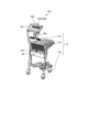
Third Embodiment
Next, a
図9は、第3の実施の形態のカートPOSの概略斜視図である。カートPOS10cは、第1の実施の形態のカートPOS10aとは異なり、タブレット端末14cの外部にバッテリセレクタ27bを備える。バッテリセレクタ27bは、バッテリ40と同じ筐体に内蔵される。なお、バッテリセレクタ27bとバッテリ40とは別体型であってもよい。
Figure 9 is a schematic perspective view of a cart POS according to the third embodiment. Unlike the
(カートPOSのハードウエア構成の説明)
図10を用いて、カートPOS10cのハードウエア構成を説明する。図10は、第3の実施の形態のカートPOSのハードウエア構成の一例を示すハードウエアブロック図である。
(Explanation of the hardware configuration of the cart POS)
The hardware configuration of the
カートPOS10cは、カートPOS10aのハードウエア構成(図2参照)において、記憶部24が備えるバッテリ状態監視ファイルBと接続デバイス管理ファイルDとを削除した構成を有する。また、カートPOS10cは、タブレット端末14cの外部にバッテリセレクタ27bを備える。
The
(バッテリの接続切替方法の説明)
カートPOS10cが備えるバッテリセレクタ27bは、例えばFETのスイッチング動作を用いて、複数の入力端子と複数の出力端子との接続の設定および接続切替を行う。より具体的には、バッテリセレクタ27bは、入力端子に接続されたバッテリ40の出力電圧をモニタする。そして、出力電圧eが電圧閾値eth以下であると判定された場合に、他のバッテリ40に接続を切り替える。また、バッテリセレクタ27bの出力端子は、タブレット端末14cと、タブレット端末14cとともに動作するデバイス30に接続される。なお、バッテリセレクタ27b自身も、バッテリ40からの給電によって動作する。
(Explanation of how to switch battery connections)
The
(カートPOSの機能構成の説明)
次に、図11を用いて、カートPOS10cの機能構成を説明する。図11は、第3の実施の形態のカートPOSの機能構成の一例を示す機能ブロック図である。
(Description of Cart POS Functional Configuration)
Next, the functional configuration of the
カートPOS10cは、タブレット端末14cの制御部20cと、バッテリセレクタ27bとデバイス30とが、互いに連携することによって動作する。
The
タブレット端末14cの制御部20cは、商品情報読取部70と、登録処理部72と、操作制御部74と、表示制御部76とを機能部として実現する。
The control unit 20c of the
商品情報読取部70は、例えばスキャナ30cによって、商品に貼付されたバーコード等のコードシンボルを読み取る。そして、商品情報読取部70は、読み取ったコードシンボルの内容と商品マスタMに登録された商品コードとを照合することによって、商品を一意に特定する。
The product information reading unit 70 reads a code symbol, such as a barcode, attached to the product, for example by using the
登録処理部72は、商品情報読取部70が特定した商品を商品登録ファイルRに登録する。
The
操作制御部74は、客がタッチパネル30bに対して行った操作情報を取得する。
The operation control unit 74 acquires information about operations performed by the customer on the
表示制御部76は、モニタ30aに出力する表示データを生成する。また、表示制御部76は、生成した表示データをモニタ30aに出力する。
The display control unit 76 generates display data to be output to the
バッテリセレクタ27bは、バッテリ電圧検出部80と、バッテリ電圧判定部82と、バッテリ接続切替部84と、タブレット端末動作モニタ部86と、給電部88とを機能部として実現する。
The
バッテリ電圧検出部80は、タブレット端末14cおよびデバイス30に接続されているバッテリ40の出力電圧eを検出する。なお、バッテリ電圧検出部80は、更に、タブレット端末14cおよびデバイス30に接続されていないバッテリ40の出力電圧eを検出してもよい。
The battery
バッテリ電圧判定部82は、バッテリ電圧検出部80が取得したバッテリ40の出力電圧eが、電圧閾値eth以下であるかを判定する。
The battery
バッテリ接続切替部84は、デバイス30に接続されたバッテリ40の出力電圧eに基づいて、接続切替後のバッテリ40の接続形態を決定する。また、バッテリ接続切替部84は、決定した接続形態になるように、バッテリ40とデバイス30との接続を切り替える。なお、バッテリ接続切替部84は、本開示における接続切替部の一例である。
The battery connection switching unit 84 determines the connection form of the
タブレット端末動作モニタ部86は、タブレット端末14cの動作状態をモニタする。より具体的には、タブレット端末動作モニタ部86は、タブレット端末14cの電源が切断されたかをモニタする。
The tablet terminal operation monitor unit 86 monitors the operating state of the
給電部88は、複数のバッテリ40a,40b,…,40nのうち、タブレット端末14cおよびデバイス30に接続されたバッテリから、タブレット端末14cおよびデバイス30に給電を行う。
The power supply unit 88 supplies power to the
(カートPOSが行う処理の流れの説明)
次に、図12と図13を用いて、カートPOS10cが行う処理の流れを説明する。図12は、第3の実施の形態のタブレット端末が行う商品登録処理の流れの一例を示すフローチャートである。図13は、第3の実施の形態のバッテリセレクタが行うバッテリ切替処理の流れの一例を示すフローチャートである。
(Explanation of the process flow performed by the cart POS)
Next, the flow of processing performed by the
まず、タブレット端末14cが行う商品登録処理の流れを説明する。
First, we will explain the flow of the product registration process performed by
商品情報読取部70は、スキャナ30cが、商品に貼付されたバーコード等のコードシンボルを読み取ったかを判定する(ステップS31)。スキャナ30cが、商品に貼付されたバーコード等のコードシンボルを読み取ったと判定される(ステップS31:Yes)とステップS32に進む。一方、商品に貼付されたバーコード等のコードシンボルを読み取ったと判定されない(ステップS31:No)とステップS31を繰り返す。
The product information reading unit 70 determines whether the
ステップS31においてYesと判定されると、商品情報読取部70は、商品を一意に特定する(ステップS32)。 If the answer is Yes in step S31, the product information reading unit 70 uniquely identifies the product (step S32).
登録処理部72は、ステップS32において一意に特定した商品を商品登録ファイルRに登録する(ステップS33)。
The
操作制御部74は、商品の登録が全て完了したかを判定する(ステップS34)。商品の登録が全て完了したと判定される(ステップS34:Yes)と、タブレット端末14cは、図12の処理を終了する。一方、商品の登録が全て完了したと判定されない(ステップS34:No)と、ステップS31に戻る。なお、商品の登録が全て完了したかは、客が、タブレット端末14cのモニタ30aに表示された小計ボタンや登録完了ボタン等の登録完了を指示するボタンを押下したことを、タッチパネル30bが検出するによって判定される。
The operation control unit 74 determines whether or not all product registration has been completed (step S34). If it is determined that all product registration has been completed (step S34: Yes), the
次に、バッテリセレクタ27bが行うバッテリ切替処理の流れを説明する。
Next, we will explain the flow of the battery switching process performed by the
バッテリ電圧検出部80は、タブレット端末14cおよびデバイス30に給電している全てのバッテリ40の出力電圧eを検出する(ステップS41)。
The battery
バッテリ電圧判定部82は、バッテリ電圧検出部80が取得した、タブレット端末14cおよびデバイス30に給電しているバッテリ40の出力電圧eが、電圧閾値eth以下であるかを判定する(ステップS42)。バッテリ40の出力電圧eが、電圧閾値eth以下であると判定される(ステップS42:Yes)とステップS43に進む。一方、バッテリ40の出力電圧eが、電圧閾値eth以下であると判定されない(ステップS42:No)とステップS41に戻る。
The battery
ステップS42においてYesと判定されると、バッテリ接続切替部84は、接続切替後の、バッテリ40とデバイス30との接続形態を決定する(ステップS43)。
If the answer is Yes in step S42, the battery connection switching unit 84 determines the connection form between the
バッテリ接続切替部84は、ステップS43で決定した接続状態になるように、バッテリ40とデバイス30との接続を切り替える(ステップS44)。
The battery connection switching unit 84 switches the connection between the
給電部88は、新たに接続されたバッテリ40から、タブレット端末14cおよびデバイス30に対して給電を行う(ステップS45)。
The power supply unit 88 supplies power to the
タブレット端末動作モニタ部86は、タブレット端末14cの電源が切断されたかを判定する(ステップS46)。タブレット端末14cの電源が切断されたと判定される(ステップS46:Yes)と、バッテリセレクタ27bは、図13の処理を終了する。一方、タブレット端末14cの電源が切断されたと判定されない(ステップS46:No)と、ステップS41に戻る。
The tablet terminal operation monitor unit 86 determines whether the
なお、本実施の形態において、タブレット端末14cは、客が購入する商品の登録処理を行うものとして説明したが、タブレット端末14cは、登録処理の後で、更に、登録された商品の決済を行う決済処理を行ってもよい。
In this embodiment, the
以上説明したように、第3の実施の形態のカートPOS10c(商品販売データ処理装置)において、バッテリ接続切替部84(接続切替部)は、タブレット端末14cおよびデバイス30に接続されたバッテリ40の出力電圧e(バッテリの状態)に基づいて、当該タブレット端末14cおよびデバイス30に給電を行うバッテリ40を切り替える。そして、給電部88は、複数のバッテリ40のうちいずれかのバッテリから、当該バッテリ40と接続されたタブレット端末14cおよびデバイス30に給電を行う。制御部20cは、デバイス30から入力された情報に基づいて、少なくとも客が購入する商品の登録処理を行う。したがって、タブレット端末14cおよびデバイス30への給電中にバッテリ40の残量が減った場合には、バッテリ40の接続切替を自動的に行うことができる。
As described above, in the
以上、本発明の実施の形態を説明したが、これらの実施の形態は、いずれも例示であり、発明の範囲を限定することは意図していない。これら新規な実施の形態は、その他の様々な形態で実施されることが可能であり、発明の要旨を逸脱しない範囲で、種々の省略、置き換え、変更を行うことができる。これら実施の形態やその変形は、発明の範囲や要旨に含まれるとともに、特許請求の範囲に記載された発明とその均等の範囲に含まれる。 Although the embodiments of the present invention have been described above, these embodiments are merely examples and are not intended to limit the scope of the invention. These novel embodiments can be embodied in various other forms, and various omissions, substitutions, and modifications can be made without departing from the gist of the invention. These embodiments and their modifications are included within the scope and gist of the invention, and are included in the scope of the invention and its equivalents as set forth in the claims.
10a,10b…カートPOS、10c…カートPOS(商品販売データ処理装置)、12…ショッピングカート、14a,14b…タブレット端末(情報処理装置)、14c…タブレット端末、20a,20b,20c…制御部、24…記憶部、25…補助バッテリ、26…入出力コントローラ、27a,27b…バッテリセレクタ、28…無線通信インタフェース、29…内部バス、30…デバイス、30a…モニタ(デバイス)、30b…タッチパネル(デバイス)、30c…スキャナ(デバイス)、30d…カードリーダ(デバイス)、40,40a,40b…バッテリ、50,80…バッテリ電圧検出部、52,82…バッテリ電圧判定部、54…動作状態取得部、56…接続デバイス検出部、58,84…バッテリ接続切替部(接続切替部)、60,88…給電部、62…動作制御部、64…電流検出部、66…消費電力積算部、68…バッテリ残量判定部、86…タブレット端末動作モニタ部、B…バッテリ状態監視ファイル、C…初期容量、Cth…残量閾値、D…接続デバイス管理ファイル、e…出力電圧、eth…電圧閾値、i…電流、M…商品マスタ、P…消費電力、P1,P2…制御プログラム、r…抵抗値 10a, 10b... Cart POS, 10c... Cart POS (product sales data processing device), 12... Shopping cart, 14a, 14b... Tablet terminal (information processing device), 14c... Tablet terminal, 20a, 20b, 20c... Control unit, 24... Memory unit, 25... Auxiliary battery, 26... Input/output controller, 27a, 27b... Battery selector, 28... Wireless communication interface, 29... Internal bus, 30... Device, 30a... Monitor (device), 30b... Touch panel (device), 30c... Scanner (device), 30d... Card reader (device), 40, 40a, 40b ...battery, 50, 80...battery voltage detection unit, 52, 82...battery voltage determination unit, 54...operation status acquisition unit, 56...connected device detection unit, 58, 84...battery connection switching unit (connection switching unit), 60, 88...power supply unit, 62...operation control unit, 64...current detection unit, 66...power consumption integration unit, 68...battery remaining capacity determination unit, 86...tablet terminal operation monitor unit, B...battery status monitoring file, C...initial capacity, Cth...remaining capacity threshold, D...connected device management file, e...output voltage, eth...voltage threshold, i...current, M...product master, P...power consumption, P1, P2...control program, r...resistance value
Claims (7)
前記デバイスに接続されたバッテリの状態と、接続デバイス検出部が検出した、前記商品販売データ処理装置に接続されているデバイスの種類と、接続デバイス管理ファイルに登録された前記デバイスの消費電力と、に基づいて、前記商品販売データ処理装置に接続されている前記デバイスを全て動作可能とするように、前記デバイスに給電を行うバッテリとその接続形態とを切り替える接続切替部と、
を備える商品販売データ処理装置。 a power supply unit that supplies power from any one of the plurality of batteries to a device that is connected to the battery and is included in the product sales data processing device ;
a connection switching unit that switches between a battery that supplies power to the device and its connection mode so that all of the devices connected to the product sales data processing device can be operated based on the state of a battery connected to the device, the type of device connected to the product sales data processing device detected by a connected device detection unit, and the power consumption of the device registered in a connected device management file; and
A product sales data processing device comprising:
前記デバイスに接続されたバッテリの出力電圧が、電圧閾値を下回ったことを条件として、当該デバイスに給電を行うバッテリを切り替える、
請求項1に記載の商品販売データ処理装置。 The connection switching unit is
switching a battery that supplies power to the device on condition that an output voltage of the battery connected to the device falls below a voltage threshold;
The product sales data processing device according to claim 1.
前記バッテリの初期容量と、当該バッテリで給電を開始してからの消費電力の積算値とに基づく前記バッテリの残量が、残量閾値を下回ったことを条件として、前記デバイスに給電を行うバッテリを切り替える、
請求項1に記載の商品販売データ処理装置。 The connection switching unit is
switching the battery that supplies power to the device on condition that a remaining capacity of the battery, which is based on an initial capacity of the battery and an integrated value of power consumption since the battery starts supplying power, falls below a remaining capacity threshold;
The product sales data processing device according to claim 1.
接続される前記デバイスの消費電力に基づいて、当該デバイス毎に異なるバッテリから給電を行うか、複数のデバイスに同じバッテリから給電を行うかを選択する、
請求項1から請求項3のいずれか1項に記載の商品販売データ処理装置。 The connection switching unit is
selecting whether to supply power from a different battery for each of the devices connected to the power supply device or to supply power to the multiple devices from the same battery based on the power consumption of the devices;
The product sales data processing device according to any one of claims 1 to 3.
前記商品販売データ処理装置の動作状態を取得する動作状態取得部が、前記商品販売データ処理装置がスタンバイ状態にあることを検出したことを条件として、前記デバイスに給電を行うバッテリとその接続形態とを切り替える、
請求項1に記載の商品販売データ処理装置。 The connection switching unit is
an operation state acquisition unit for acquiring an operation state of the product sales data processing device , when the product sales data processing device is detected to be in a standby state, switches between a battery that supplies power to the device and a connection form thereof;
The product sales data processing device according to claim 1.
請求項1に記載の商品販売データ処理装置。 an auxiliary battery that is charged by the battery and maintained in a fully charged state, the auxiliary battery powering the device when the battery is disconnected;
The product sales data processing device according to claim 1.
複数のバッテリのうちいずれかのバッテリから、当該バッテリと接続された、商品販売データ処理装置が備えるデバイスに給電を行う給電部と、
前記デバイスに接続されたバッテリの状態と、接続デバイス検出部が検出した、前記商品販売データ処理装置に接続されているデバイスの種類と、接続デバイス管理ファイルに登録された前記デバイスの消費電力と、に基づいて、前記商品販売データ処理装置に接続されている前記デバイスを全て動作可能とするように、前記デバイスに給電を行うバッテリとその接続形態とを切り替える接続切替部と、
して機能させるプログラム。 A computer that controls a product sales data processing device,
a power supply unit that supplies power from any one of the plurality of batteries to a device that is connected to the battery and is included in the product sales data processing device ;
a connection switching unit that switches between a battery that supplies power to the device and its connection mode so as to make all of the devices connected to the product sales data processing device operable, based on the state of a battery connected to the device, the type of device connected to the product sales data processing device detected by a connected device detection unit, and the power consumption of the device registered in a connected device management file; and
A program that makes it work.
Priority Applications (3)
| Application Number | Priority Date | Filing Date | Title |
|---|---|---|---|
| JP2020141559A JP7561542B2 (en) | 2020-08-25 | 2020-08-25 | Product sales data processing device and program |
| US17/337,986 US20220069604A1 (en) | 2020-08-25 | 2021-06-03 | Information processing apparatus, merchandise sales data processing apparatus, and program |
| EP21184276.0A EP3961350A1 (en) | 2020-08-25 | 2021-07-07 | Information processing apparatus, merchandise sales data processing apparatus, and program |
Applications Claiming Priority (1)
| Application Number | Priority Date | Filing Date | Title |
|---|---|---|---|
| JP2020141559A JP7561542B2 (en) | 2020-08-25 | 2020-08-25 | Product sales data processing device and program |
Publications (2)
| Publication Number | Publication Date |
|---|---|
| JP2022037427A JP2022037427A (en) | 2022-03-09 |
| JP7561542B2 true JP7561542B2 (en) | 2024-10-04 |
Family
ID=77126510
Family Applications (1)
| Application Number | Title | Priority Date | Filing Date |
|---|---|---|---|
| JP2020141559A Active JP7561542B2 (en) | 2020-08-25 | 2020-08-25 | Product sales data processing device and program |
Country Status (3)
| Country | Link |
|---|---|
| US (1) | US20220069604A1 (en) |
| EP (1) | EP3961350A1 (en) |
| JP (1) | JP7561542B2 (en) |
Citations (6)
| Publication number | Priority date | Publication date | Assignee | Title |
|---|---|---|---|---|
| JP2009278754A (en) | 2008-05-14 | 2009-11-26 | Casio Comput Co Ltd | Electronic equipment, power supply control method and program |
| JP2010152547A (en) | 2008-12-24 | 2010-07-08 | Casio Computer Co Ltd | Electronic equipment, power supply control method, and program |
| JP2012108032A (en) | 2010-11-18 | 2012-06-07 | Panasonic Corp | Device and method of controlling secondary battery |
| US20130232370A1 (en) | 2012-03-02 | 2013-09-05 | Toshiba Tec Kabushiki Kaisha | Information processor and a battery management method for information processors |
| JP2013182592A (en) | 2012-03-05 | 2013-09-12 | Toshiba Tec Corp | Pos terminal |
| JP2013214289A (en) | 2012-04-02 | 2013-10-17 | Toshiba Tec Corp | Money registration device and money registration device power supply management method |
Family Cites Families (14)
| Publication number | Priority date | Publication date | Assignee | Title |
|---|---|---|---|---|
| JPS61246820A (en) * | 1985-04-24 | 1986-11-04 | Canon Inc | Electronic appliance |
| JP3733554B2 (en) * | 1994-10-31 | 2006-01-11 | 富士通株式会社 | Battery-powered electronic equipment |
| US5773954A (en) * | 1996-06-26 | 1998-06-30 | Telxon Corporation | Battery charging station for shopping cart mounted portable data collection devices |
| IL121778A (en) * | 1997-09-16 | 2001-01-11 | Hillel Hillel | Lift transit vehicle |
| KR100584324B1 (en) * | 2003-08-22 | 2006-05-26 | 삼성전자주식회사 | Power control device of composite terminal |
| TWI451234B (en) * | 2011-08-10 | 2014-09-01 | Askey Technology Jiang Su Ltd | Data processor with battery replaceable under un-shutdown state, and method for replacing battery under un-shutdown state |
| US9002413B2 (en) * | 2012-10-25 | 2015-04-07 | Terrence Michael Furtney | Battery cell phone combination |
| US9240685B2 (en) * | 2013-01-21 | 2016-01-19 | Hamilton Sundstrand Corporation | Reconfigurable matrix-based power distribution architecture |
| WO2016205629A1 (en) * | 2015-06-17 | 2016-12-22 | Panasonic Intellectual Property Management Co., Ltd. | Stock management apparatus, method and system |
| US9796402B1 (en) * | 2015-10-13 | 2017-10-24 | Michael Suarez | Electronic shopping cart |
| CN206012763U (en) | 2016-08-15 | 2017-03-15 | 美国锐哲有限公司 | A kind of kart |
| US10716192B1 (en) * | 2017-08-30 | 2020-07-14 | Roman Tsibulevskiy | Charging technologies |
| JP6833661B2 (en) * | 2017-11-09 | 2021-02-24 | 東芝テック株式会社 | Acquisition device, acquisition system and program |
| US11515712B2 (en) * | 2019-05-22 | 2022-11-29 | Samsung Electronics Co., Ltd. | Battery including battery sub packs for increasing battery capacity |
-
2020
- 2020-08-25 JP JP2020141559A patent/JP7561542B2/en active Active
-
2021
- 2021-06-03 US US17/337,986 patent/US20220069604A1/en not_active Abandoned
- 2021-07-07 EP EP21184276.0A patent/EP3961350A1/en active Pending
Patent Citations (6)
| Publication number | Priority date | Publication date | Assignee | Title |
|---|---|---|---|---|
| JP2009278754A (en) | 2008-05-14 | 2009-11-26 | Casio Comput Co Ltd | Electronic equipment, power supply control method and program |
| JP2010152547A (en) | 2008-12-24 | 2010-07-08 | Casio Computer Co Ltd | Electronic equipment, power supply control method, and program |
| JP2012108032A (en) | 2010-11-18 | 2012-06-07 | Panasonic Corp | Device and method of controlling secondary battery |
| US20130232370A1 (en) | 2012-03-02 | 2013-09-05 | Toshiba Tec Kabushiki Kaisha | Information processor and a battery management method for information processors |
| JP2013182592A (en) | 2012-03-05 | 2013-09-12 | Toshiba Tec Corp | Pos terminal |
| JP2013214289A (en) | 2012-04-02 | 2013-10-17 | Toshiba Tec Corp | Money registration device and money registration device power supply management method |
Also Published As
| Publication number | Publication date |
|---|---|
| US20220069604A1 (en) | 2022-03-03 |
| JP2022037427A (en) | 2022-03-09 |
| EP3961350A1 (en) | 2022-03-02 |
Similar Documents
| Publication | Publication Date | Title |
|---|---|---|
| JP7513150B2 (en) | Information processing system, information processing method, and program | |
| KR101589010B1 (en) | Method and Apparatus for Recommending Product Using Visible Light Communication | |
| JP5228010B2 (en) | Product information processing apparatus and program | |
| US8447709B2 (en) | Information terminal and control method for storing image pickup data of a sales floor, and totaling and displaying sales data | |
| JP7630030B2 (en) | Programs and mobile devices | |
| JP2020067974A (en) | Registration device and program | |
| EP3855197A1 (en) | State of charge measurement apparatus | |
| Sanap et al. | SMART-smart mobile autonomous robotic trolley | |
| JP7561542B2 (en) | Product sales data processing device and program | |
| JP6655427B2 (en) | Information processing device and program | |
| JP2019114187A (en) | POS system and monitoring device | |
| JP2014193010A (en) | Electronic apparatus | |
| EP3817460B1 (en) | Information processing system and method | |
| JP6001878B2 (en) | Power storage recovery system, power storage device, power storage recovery device, and power storage recovery method | |
| JP7105585B2 (en) | Payment terminal and program | |
| JP2013037452A (en) | Congestion degree notification device, program and congestion degree notification method | |
| JP7813683B2 (en) | Accounting device, data processing system and program | |
| JP2023027222A (en) | system and equipment | |
| JP7180211B2 (en) | Information processing system, information processing method and program | |
| JP2018201327A (en) | Charging method and program | |
| WO2011113090A1 (en) | Product ticketing system | |
| JP7147226B2 (en) | POS terminal, POS system and information processing method | |
| JP5689906B2 (en) | Money registration apparatus and power management method for money registration apparatus | |
| US20220092630A1 (en) | Digital signage terminal | |
| JP7297046B2 (en) | mobile terminal |
Legal Events
| Date | Code | Title | Description |
|---|---|---|---|
| A621 | Written request for application examination |
Free format text: JAPANESE INTERMEDIATE CODE: A621 Effective date: 20230519 |
|
| A977 | Report on retrieval |
Free format text: JAPANESE INTERMEDIATE CODE: A971007 Effective date: 20240125 |
|
| A131 | Notification of reasons for refusal |
Free format text: JAPANESE INTERMEDIATE CODE: A131 Effective date: 20240213 |
|
| A521 | Request for written amendment filed |
Free format text: JAPANESE INTERMEDIATE CODE: A523 Effective date: 20240402 |
|
| A131 | Notification of reasons for refusal |
Free format text: JAPANESE INTERMEDIATE CODE: A131 Effective date: 20240604 |
|
| A521 | Request for written amendment filed |
Free format text: JAPANESE INTERMEDIATE CODE: A523 Effective date: 20240801 |
|
| TRDD | Decision of grant or rejection written | ||
| A01 | Written decision to grant a patent or to grant a registration (utility model) |
Free format text: JAPANESE INTERMEDIATE CODE: A01 Effective date: 20240903 |
|
| A61 | First payment of annual fees (during grant procedure) |
Free format text: JAPANESE INTERMEDIATE CODE: A61 Effective date: 20240924 |
|
| R150 | Certificate of patent or registration of utility model |
Ref document number: 7561542 Country of ref document: JP Free format text: JAPANESE INTERMEDIATE CODE: R150 |