JP7558905B2 - Motor control device and air conditioner - Google Patents
Motor control device and air conditioner Download PDFInfo
- Publication number
- JP7558905B2 JP7558905B2 JP2021129010A JP2021129010A JP7558905B2 JP 7558905 B2 JP7558905 B2 JP 7558905B2 JP 2021129010 A JP2021129010 A JP 2021129010A JP 2021129010 A JP2021129010 A JP 2021129010A JP 7558905 B2 JP7558905 B2 JP 7558905B2
- Authority
- JP
- Japan
- Prior art keywords
- current
- vector
- torque
- motor
- current command
- Prior art date
- Legal status (The legal status is an assumption and is not a legal conclusion. Google has not performed a legal analysis and makes no representation as to the accuracy of the status listed.)
- Active
Links
Images


Classifications
-
- H—ELECTRICITY
- H02—GENERATION; CONVERSION OR DISTRIBUTION OF ELECTRIC POWER
- H02P—CONTROL OR REGULATION OF ELECTRIC MOTORS, ELECTRIC GENERATORS OR DYNAMO-ELECTRIC CONVERTERS; CONTROLLING TRANSFORMERS, REACTORS OR CHOKE COILS
- H02P21/00—Arrangements or methods for the control of electric machines by vector control, e.g. by control of field orientation
- H02P21/05—Arrangements or methods for the control of electric machines by vector control, e.g. by control of field orientation specially adapted for damping motor oscillations, e.g. for reducing hunting
-
- H—ELECTRICITY
- H02—GENERATION; CONVERSION OR DISTRIBUTION OF ELECTRIC POWER
- H02P—CONTROL OR REGULATION OF ELECTRIC MOTORS, ELECTRIC GENERATORS OR DYNAMO-ELECTRIC CONVERTERS; CONTROLLING TRANSFORMERS, REACTORS OR CHOKE COILS
- H02P21/00—Arrangements or methods for the control of electric machines by vector control, e.g. by control of field orientation
- H02P21/14—Estimation or adaptation of machine parameters, e.g. flux, current or voltage
- H02P21/18—Estimation of position or speed
-
- F—MECHANICAL ENGINEERING; LIGHTING; HEATING; WEAPONS; BLASTING
- F24—HEATING; RANGES; VENTILATING
- F24F—AIR-CONDITIONING; AIR-HUMIDIFICATION; VENTILATION; USE OF AIR CURRENTS FOR SCREENING
- F24F11/00—Control or safety arrangements
- F24F11/30—Control or safety arrangements for purposes related to the operation of the system, e.g. for safety or monitoring
-
- H—ELECTRICITY
- H02—GENERATION; CONVERSION OR DISTRIBUTION OF ELECTRIC POWER
- H02K—DYNAMO-ELECTRIC MACHINES
- H02K11/00—Structural association of dynamo-electric machines with electric components or with devices for shielding, monitoring or protection
- H02K11/30—Structural association with control circuits or drive circuits
-
- H—ELECTRICITY
- H02—GENERATION; CONVERSION OR DISTRIBUTION OF ELECTRIC POWER
- H02P—CONTROL OR REGULATION OF ELECTRIC MOTORS, ELECTRIC GENERATORS OR DYNAMO-ELECTRIC CONVERTERS; CONTROLLING TRANSFORMERS, REACTORS OR CHOKE COILS
- H02P25/00—Arrangements or methods for the control of AC motors characterised by the kind of AC motor or by structural details
- H02P25/02—Arrangements or methods for the control of AC motors characterised by the kind of AC motor or by structural details characterised by the kind of motor
- H02P25/022—Synchronous motors
-
- H—ELECTRICITY
- H02—GENERATION; CONVERSION OR DISTRIBUTION OF ELECTRIC POWER
- H02P—CONTROL OR REGULATION OF ELECTRIC MOTORS, ELECTRIC GENERATORS OR DYNAMO-ELECTRIC CONVERTERS; CONTROLLING TRANSFORMERS, REACTORS OR CHOKE COILS
- H02P6/00—Arrangements for controlling synchronous motors or other dynamo-electric motors using electronic commutation dependent on the rotor position; Electronic commutators therefor
- H02P6/08—Arrangements for controlling the speed or torque of a single motor
Landscapes
- Engineering & Computer Science (AREA)
- Power Engineering (AREA)
- Chemical & Material Sciences (AREA)
- Combustion & Propulsion (AREA)
- Mechanical Engineering (AREA)
- General Engineering & Computer Science (AREA)
- Control Of Ac Motors In General (AREA)
Description
本発明の実施形態は、モータを位置センサレス方式で制御するモータ制御装置、及びそのモータ制御装置によりモータを制御して圧縮機を駆動する空調機に関する。 Embodiments of the present invention relate to a motor control device that controls a motor using a position sensorless method, and an air conditioner that controls a motor using the motor control device to drive a compressor.
例えば、ブラシレスDCモータを圧縮機のモータとして使用する場合、モータの回転速度や位置を位置センサレス方式により推定し、推定した回転速度と目標回転速度とに差異があれば電流指令又は電圧指令を変化させ、モータの回転速度を目標回転速度に調整する制御を行なう場合がある。 For example, when a brushless DC motor is used as a compressor motor, the rotational speed and position of the motor are estimated using a position sensorless method, and if there is a difference between the estimated rotational speed and the target rotational speed, the current command or voltage command is changed to control the motor rotational speed to the target rotational speed.
図15は、1シリンダ型のロータリコンプレッサの断面構造を示すが、このような圧縮機ではその機構により、図16に示すように、コンプレッサモータの回転機械角に応じて負荷変動が発生する。この負荷変動によりモータが機械角で1回転する間に回転速度にむらが発生し、振動や騒音の発生に繋がる。モータに回転速度むらがある状態で圧縮機の運転を継続すると、例えば空調機においては冷媒等を輸送する配管にストレスがかかり、これらの寿命を低下させる。したがって、モータを回転制御する際にはトルク制御を行い、負荷変動に伴う回転速度むらの発生を抑制する必要がある。 Figure 15 shows the cross-sectional structure of a one-cylinder rotary compressor, and this type of compressor has a mechanism that causes load fluctuations in response to the rotational mechanical angle of the compressor motor, as shown in Figure 16. This load fluctuation causes fluctuations in the rotational speed of the motor as it rotates through one mechanical angle, leading to vibration and noise. If the compressor continues to operate with uneven rotational speed in the motor, for example in an air conditioner, stress is placed on the pipes that transport refrigerant, shortening their lifespan. Therefore, when controlling the rotation of the motor, it is necessary to perform torque control and suppress the occurrence of uneven rotational speed due to load fluctuations.
このような目的でトルク制御を行う従来技術として、特許文献1には以下のような構成が開示されている。トルク電流、モータ定数及び圧縮機の圧縮部を含むモータの慣性モーメントから、圧縮機が発生する負荷トルクを推定する。負荷トルクが示す周期的な変動の位相を演算し、負荷トルク位相に基づいて正弦波状のトルク補正電流を決定し、モータの速度変動を減少させるようにトルク補正電流の振幅・位相を調整する。また、特許文献2には、外乱オブザーバにより推定した負荷トルクと、決定されたモータの駆動に関するパラメータとにより、トルク指令値を補償する技術が開示されている。
As a conventional technique for torque control for such purposes,
しかしながら、特許文献1及び2のような技術では、速度制御や電流制御に比例積分制御を使用しているので、電流指令や電圧指令が徐々に決定される。すなわち、フィードバック制御に過去の情報を使うことで遅れが生じ、制御応答性が低い。更に、位置センサレス方式を採用してモータの位置を推定する際には、モータ位置や速度の推定精度が低下すれば正確なトルク制御ができなくなる。したがって、トルク変動が非常に短い周期で発生する場合には、速度変動を十分に抑制できなくなるおそれがある。
However, in technologies such as those disclosed in
そこで、比較的大きな負荷変動が生じることが前提のシステムに位置センサレス方式でのモータ制御を適用する際に、目標速度に高速で追従できるモータ制御装置、及びそのモータ制御装置を備えてなる空調機を提供する。 Therefore, we provide a motor control device that can track a target speed at high speed when applying motor control using a position sensorless method to a system that assumes relatively large load fluctuations, and an air conditioner equipped with this motor control device.
実施形態のモータ制御装置は、負荷を駆動するモータに交流電力を供給する電力供給部と、
前記モータの巻線に流れる電流を検出する電流検出部と、
前記電流供給部が出力する電圧と前記電流とに基づいて、前記モータの回転速度及び電気角を推定する速度・電気角推定部と、
前記電流と前記電気角とに基づいて、励磁電流及びトルク電流を得る座標変換部と、
永久磁石同期モータのベクトル制御座標のトルク式に基づき算出されるトルク成分電流指令値に、機械系の運動方程式に基づき算出した予測トルクを代入することで、入力される速度指令と推定された速度との差分をゼロに近付けるトルク成分電流指令値を生成するトルク電流指令決定部と、
前記電力供給部が出力可能な、空間電圧ベクトルに基づく複数のスイッチングパターンのそれぞれに応じて決まる電流変化率を含む複数の予測電流に対し、前記トルク成分電流指令値及び外部より入力される励磁成分電流指令値それぞれに対応する予測電流との差の大きさを評価する評価関数を適用することで、スイッチングパターンを選択して出力するモデル予測制御部とを備える。
The motor control device according to the embodiment includes: a power supply unit that supplies AC power to a motor that drives a load;
a current detection unit that detects a current flowing through a winding of the motor;
a speed/electrical angle estimating unit that estimates a rotation speed and an electrical angle of the motor based on the voltage output by the current supplying unit and the current;
a coordinate conversion unit that obtains an excitation current and a torque current based on the current and the electrical angle;
a torque current command determination unit that generates a torque component current command value that brings a difference between an input speed command and an estimated speed closer to zero by substituting a predicted torque calculated based on an equation of motion of a mechanical system into a torque component current command value calculated based on a torque equation of a vector control coordinate of a permanent magnet synchronous motor;
and a model predictive control unit that selects and outputs a switching pattern by applying an evaluation function that evaluates the magnitude of a difference between a plurality of predicted currents including a current change rate determined according to each of a plurality of switching patterns based on a space voltage vector that can be output by the power supply unit and a predicted current corresponding to each of the torque component current command values and an excitation component current command value input from outside.
また、実施形態の空調機は、
圧縮機と、
この圧縮機を駆動するモータと、
請求項1から5の何れか一項に記載のモータ制御装置とを備える。
In addition, the air conditioner of the embodiment includes:
A compressor;
A motor that drives the compressor;
The motor control device according to any one of
(第1実施形態)
図1は、モータ制御装置の構成を示す機能ブロック図である。電力供給部であるインバータ回路1は、図示しないが、半導体スイッチング素子である例えばIGBTを6個用い、これらを三相ブリッジ接続して構成されている。インバータ回路1の各相出力端子は、永久磁石型同期モータであるブラシレスDCモータ2の、例えばスター結線されている各相巻線の各端子に接続されている。
First Embodiment
Fig. 1 is a functional block diagram showing the configuration of a motor control device. An
電流検出部3u、3v、3wは、インバータ回路1の出力線に設けられた例えばカレントトランスあり、U、V、W各相の電流Iu、Iv、Iwを検出する。尚、何れか二相の電流を検出して、残り一相の電流は演算で求めても良い。これらの電流検出部3u、3v、3wからの電流検出信号は座標変換部4に入力され、図示しないA/D変換器によりデジタルデータに変換される。座標変換部4は、三相の電流Iu、Iv、Iwを二相の電流Iα、Iβに変換し、速度・電気角推定部である位置推定部5で推定される回転位相角θに基づいて、静止座標系の電流Iα、Iβを回転座標系のd軸電流Id、q軸電流Iqに変換する。
The
トルク電流指令決定部であるq軸電流指令生成部6は、指令速度ωref、位置推定部5で推定されたモータの角速度の積分値ω_I、負荷トルク、d軸電流指令、モータ定数及びサンプリング周期を用いて演算を行う。そして、モータ速度ωが指令速度ωrefに追従するようにq軸電流指令Iqrefを生成し、モデル予測制御部7に出力する。その詳細については後述する。また、モデル予測制御部7に入力する励磁電流指令Idrefは、通常はゼロに設定し、弱め界磁制御等を行う際には負の値を設定する。
The q-axis current
モデル予測制御部7は、直流電圧VDC、モータ速度ω、回転位相角θ、座標変換部4で変換されたd軸電流Id、q軸電流Iq、モータ定数及びサンプリング周期を用いて、インバータ回路1が出力可能な8つのスイッチングパターンを試行した時のd軸・q軸電流Id、Iqをそれぞれ予測する。
The model
評価関数は、例えば、予測したd軸電流Idと励磁電流指令Idref、q軸電流Iqとq軸電流指令生成部6より与えられるq軸電流指令Iqrefとが、それぞれ最も近付くことを判別するための数式である。モデル予測制御部7は、評価関数を用いた評価結果に基づいて最適なスイッチングパターンを選択し、インバータ回路1に出力する。選択したスイッチングパターンに基づく三相のデューティ指令値Du、Dv、Dwは、スイッチング信号生成部8によりスイッチング信号に変換されて、インバータ回路1を構成する各IGBTのゲートに与えられる。
The evaluation function is, for example, a mathematical expression for determining whether the predicted d-axis current Id and the excitation current command Idref , and the q -axis current Iq and the q-axis current command Iqref provided by the q-axis current
以上について、インバータ回路1を除く構成部分は、マイコンが実行するソフトウェア処理により実現されており、ベクトル制御及びモデル予測制御を行うモータ制御装置10を構成している。例えばそのマイコンには、具体的には図示しないが、入出力ポート、シリアル通信回路、電流検出信号などのアナログ信号を入力するためのA/Dコンバータ、PWM制御を行うためのタイマなどが具備されている。
The components other than the
図2は、モータ制御装置が適用される空調機の構成を示す。空調機21を構成する圧縮機22は、圧縮部23とモータ2を同一の鉄製密閉容器25内に収容して構成され、モータ2のロータシャフトが圧縮部23に連結されている。そして、圧縮機22、四方弁26、室内側熱交換器27、減圧装置28、室外側熱交換器29は、冷媒通路たるパイプにより閉ループを構成するように接続されている。尚、圧縮機22は、例えばロータリ型の1シリンダ型の圧縮機である。
Figure 2 shows the configuration of an air conditioner to which the motor control device is applied. The
暖房時には、四方弁26は実線で示す状態にあり、圧縮機22の圧縮部23で圧縮された高温冷媒は、四方弁26から室内側熱交換器27に供給されて凝縮し、その後、減圧装置28で減圧され、低温となって室外側熱交換器29に流れ、ここで蒸発して圧縮機22へと戻る。一方、冷房時には、四方弁26は破線で示す状態に切り替えられる。このため、圧縮機22の圧縮部23で圧縮された高温冷媒は、四方弁26から室外側熱交換器29に供給されて凝縮し、その後、減圧装置28で減圧され、低温となって室内側熱交換器27に流れ、ここで蒸発して圧縮機22へと戻る。そして、室内側、室外側の各熱交換器27、29には、それぞれファン30、31により送風が行われ、その送風によって各熱交換器27、29と室内空気、室外空気の熱交換が効率良く行われるように構成されている。
During heating, the four-
次に、本実施形態の作用の原理を、図3から図8を参照して説明する。図3に示すように、モデル予測制御部7は、第1ステップとして予測電流の算出を行い、第2ステップとして評価関数によるスイッチングパターンの選択を行う。第1ステップでは、電流変化率を用いて、各スイッチングパターンを試行した際の1制御周期後の電流を予測する。先ず、零ベクトル時のd軸及びq軸電流変化率Sd0、Sq0は、永久磁石同期モータの電圧方程式に基づいて次式で求めることができる。
Next, the principle of operation of this embodiment will be described with reference to Fig. 3 to Fig. 8. As shown in Fig. 3, the model

ここで、R:巻線抵抗[Ω]、Ld:d軸インダクタンス[H]、Lq:q軸インダクタンス[H]、Id:d軸電流[A]、Iq:q軸電流[A]、φ:鎖交磁束[Wb]、ω:推定速度[rad/sec]である。 Here, R is winding resistance [Ω], L d is d-axis inductance [H], L q is q-axis inductance [H], I d is d-axis current [A], I q is q-axis current [A], φ is flux linkage [Wb], and ω is estimated speed [rad/sec].
続いて、有効ベクトル時のd軸及びq軸電流変化率Sd1、Sq1は、(1)式、(2)式を用いて次式で求めることができる。 Next, the d-axis and q-axis current change rates S d1 and S q1 at the time of the effective vector can be obtained by the following equation using equations (1) and (2).

ここで、Vd:d軸電圧[V]、Vq:q軸電圧[V]である。 Here, V d is the d-axis voltage [V], and V q is the q-axis voltage [V].
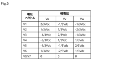
図4は試行するスイッチングパターンを示す、図5はスイッチングパターンとモータ三相電圧との関係を示す。8種類のスイッチングパターンV0~V7を順に試行し、各スイッチングパターンに対応したモータ三相電圧を生成する。そして、モータ三相電圧を回転位相角θを用いて座標変換することで、指令するd軸電圧Vd、q軸電圧Vqを次式で求める。但し、相対変換の場合である。d軸電圧Vdは位置推定演算に使用される。 Fig. 4 shows the switching patterns to be tried, and Fig. 5 shows the relationship between the switching patterns and the motor three-phase voltages. Eight switching patterns V0 to V7 are tried in order, and the motor three-phase voltages corresponding to each switching pattern are generated. The motor three-phase voltages are then coordinate-transformed using the rotation phase angle θ to determine the d-axis voltage V d and q-axis voltage V q to be commanded using the following equations. However, this is the case for relative transformation. The d-axis voltage V d is used in the position estimation calculation.

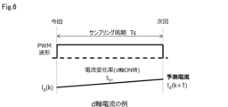
d軸電圧Vd、q軸電圧Vqは、試行するスイッチングパターンにより変化するので、(3)式、(4)式で求められるSd1、Sq1も変化し、演算結果は8通りとなる。図6に示すように、試行するスイッチングパターンをサンプリング周期でフルONとした場合、1制御周期後の次回予測電流Id(k+1)は、今回電流Id(k)と(3)式、(4)式を用いて次式で求められる。この場合、電流の予測周期は、サンプリング周期Ts[sec]に等しい。Sd1、Sq1と同様に、次回予測電流Id(k+1)も試行する通電パターンの数、すなわち8通り存在する。尚、V0とV7の試行結果は等しく、評価関数によりどちらかが選択される。この点については後述する。
Id(k+1)=Id(k)+TsSd1 (7)
Iq(k+1)=Iq(k)+TsSq1 (8)
Since the d-axis voltage Vd and the q-axis voltage Vq change depending on the switching pattern to be tried, Sd1 and Sq1 calculated by the formulas (3) and (4) also change, resulting in eight different calculation results. As shown in FIG. 6, when the switching pattern to be tried is full-on in the sampling period, the next predicted current Id (k+1) after one control period is calculated by the following formula using the current current Id (k) and the formulas (3) and (4). In this case, the current prediction period is equal to the sampling period Ts [sec]. As with Sd1 and Sq1 , the next predicted current Id (k+1) also has the number of tried current patterns, i.e., eight different ones. Note that the trial results for V0 and V7 are equal, and one of them is selected by the evaluation function. This point will be described later.
I d (k+1)=I d (k)+T s S d1 (7)
I q (k+1)=I q (k)+T s S q1 (8)
次に、第2ステップのスイッチングパターン選択を説明する。(7)式、(8)式から算出した各スイッチングパターンでの次回予測電流Id(k+1)、Iq(k+1)を用いて、次式の評価関数gを解く。
g=agq+bgd (9)
gq=[{Iqref-Iq(k+1)}]2 (10)
gd=[{Idref-Id(k+1)}]2 (11)
ここで、a、b:重み係数、gq:q軸電流の評価式、gd:d軸電流の評価式である。
Next, the selection of the switching pattern in the second step will be described. The next predicted currents I d (k+1) and I q (k+1) for each switching pattern calculated from equations (7) and (8) are used to solve the following evaluation function g.
g=ag q +bg d (9)
g q = [{I qref −I q (k+1)}] 2 (10)
g d = [{I dref −I d (k+1)}] 2 (11)
Here, a and b are weighting coefficients, g q is an evaluation formula for the q-axis current, and g d is an evaluation formula for the d-axis current.
(10)式のgq及び(11)式のgdは、指令値と次回予測電流の差分の2乗であり、これらに重み係数a、bを乗じて加算した値を(9)式の評価関数gとしている。評価関数gが最小の時に次回予測電流が最も電流指令に近付くため、8種類のスイッチングパターンから最適な1つを選択できる。今回は一例として(9)式の評価関数gを示したが、要求されるインバータ回路1の駆動条件に応じて、評価関数を変更しても良い。例えば、インバータ回路1のスイッチング損失を低減するため、評価関数にスイッチングパターンの遷移条件を追加する。具体的には、三相の半導体スイッチング素子の状態変化の総数が1以下となるようにして、スイッチングパターンの遷移を限定しても良い。有効ベクトルV1~V6から零ベクトルV0、V7へ遷移する場合を例に説明すると、V1、V3、V5の場合はV0へ、V2、V4、V6の場合はV7へと遷移する。インバータ回路1の最終的な出力電圧として、選択されたスイッチングパターンを100%デューティの信号として出力する。
gq in equation (10) and gd in equation (11) are squares of the difference between the command value and the next predicted current, and the value obtained by multiplying these by weighting coefficients a and b and adding them is the evaluation function g in equation (9). When the evaluation function g is minimum, the next predicted current is closest to the current command, so that an optimal one can be selected from eight types of switching patterns. The evaluation function g in equation (9) is shown as an example this time, but the evaluation function may be changed according to the required driving conditions of the
尚、実機において、モデル予測制御で決定されたスイッチング信号は、1制御周期後に更新・出力される。そして、そのスイッチング信号により流れる電流は、2制御周期後に検出される。よって、実機では、モデル予測制御は、1制御周期後の通電パターンを試行して2制御周期後の電流を予測し、その予測電流が今回の電流指令に最も近付くスイッチングパターンを選択することになる。 In addition, in an actual machine, the switching signal determined by model predictive control is updated and output after one control cycle. The current that flows due to that switching signal is detected after two control cycles. Therefore, in an actual machine, model predictive control tries out the current pattern after one control cycle to predict the current after two control cycles, and selects the switching pattern that brings the predicted current closest to the current command.
次に、q軸電流指令生成部6について説明する。図1において、モデル予測制御部7には、q軸電流指令Iqrefとd軸電流指令Idrefが入力されている。q軸電流指令Iqrefはq軸電流指令生成部6で演算されるが、d軸電流指令Idrefは、本実施形態ではゼロとしている。q軸電流指令生成部6では、圧縮機22の振動を低減するため、速度指令ωrefと推定速度ωとの差分がゼロとなるトルクを発生させるq軸電流指令Iqrefを演算する。q軸電流変化指令Iqrefの演算式は、モデル予測制御における予測速度と予測トルクの演算式から求めており、予測速度ω(k+1)は、機械系の運動方程式から次式で表される。
Next, the q-axis current
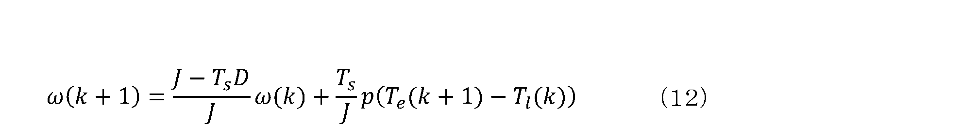
ここで、J:慣性モーメント[kg・m2]、D:粘性摩擦係数[Nm/(rad/sec)]、p:極対数、Te:出力トルク[Nm]、Tl:負荷トルク[Nm]、ω:角速度[rad/sec]である。
(12)式を次回出力トルクTe(k+1)について解くと、次式が得られる。
Here, J is the moment of inertia [kg·m 2 ], D is the viscous friction coefficient [Nm/(rad/sec)], p is the number of pole pairs, Te is the output torque [Nm], Tl is the load torque [Nm], and ω is the angular velocity [rad/sec].
When equation (12) is solved for the next output torque T e (k+1), the following equation is obtained.

尚、位置センサレス制御の場合、(12)式、(13)式の今回の速度ω(k)には、推定速度ωではなく、推定速度の積分値ω_Iを使用する。これを推定速度(積分)ω_Iとする。モデル予測制御では、d軸電圧Vd、q軸電圧Vqがサンプリング周期毎に大きく変化するので、その結果、位置誤差情報を含むd軸誘起電圧Edも同様に大きく変化する。したがって、推定速度ωには制御周期毎の大きな変動成分が含まれる。そこで、推定速度(積分)ω_Iを用いて、q軸電流指令Iqrefにサンプリング周期毎の変動成分が含まれないようにする。(13)式において、予測速度ω(k+1)を速度指令ωrefに近付けるように次回出力トルクTe(k+1)を決定するので、(13)式は次式のように置き換えることができる。 In the case of position sensorless control, the current speed ω(k) in equations (12) and (13) uses the integral value ω_I of the estimated speed, rather than the estimated speed ω. This is called the estimated speed (integral) ω_I. In model predictive control, the d-axis voltage V d and the q-axis voltage V q change significantly for each sampling period, and as a result, the d-axis induced voltage E d containing the position error information also changes significantly. Therefore, the estimated speed ω contains a large fluctuation component for each control period. Therefore, the estimated speed (integral) ω_I is used to prevent the q-axis current command I qref from containing a fluctuation component for each sampling period. In equation (13), the next output torque T e (k+1) is determined so as to bring the predicted speed ω(k+1) close to the speed command ω ref , so that equation (13) can be replaced by the following equation.
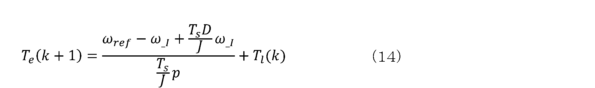
(14)式で示される次回出力トルクは、速度指令と推定速度(積分)の差分がゼロになるトルクと負荷トルクとの合計値である。続いて、次回出力トルクである予測トルクは、永久磁石同期モータのベクトル制御座標のトルク式から次式で表される。
Te(k+1)
=p{φIq(k+1)+(Ld-Lq)Id(k+1)Iq(k+1)} (15)
(15)式をIq(k+1)について解くと、次式が得られる。
The next output torque shown in equation (14) is the sum of the torque at which the difference between the speed command and the estimated speed (integral) becomes zero and the load torque. Next, the predicted torque, which is the next output torque, is expressed by the following equation from the torque equation of the vector control coordinates of the permanent magnet synchronous motor.
Te (k+1)
=p{φI q (k+1)+(L d -L q )I d (k+1)I q (k+1)} (15)
By solving equation (15) for I q (k+1), the following equation is obtained.

(16)式において、各予測電流Iq(k+1)、Id(k+1)を、それぞれ電流指令Iqref、Idrefに近付けるようにして、(14)式を代入すると、(16)式は次式のように置き換えられ、圧縮機22の振動を低減するq軸電流指令Iqrefを算出できる。
In equation (16), by substituting equation (14) so that the predicted currents Iq (k+1), Id (k+1) approach the current commands Iqref , Idref , respectively, equation (16) can be replaced by the following equation, and the q-axis current command Iqref that reduces the vibration of the

(17)式より、q軸電流指令Iqrefは、速度指令と速度推定(積分)の差分がゼロとなるトルクと、負荷トルクとに基づいて算出される。前者のトルクは、上記の速度差分にゲインを掛けることで、制御量を調整可能としている。後者の負荷トルクTlは、例えば、特許文献1のような従来技術により推定した結果を用いる。
From equation (17), the q-axis current command Iqref is calculated based on the torque at which the difference between the speed command and the speed estimate (integral) becomes zero, and the load torque. The former torque can be adjusted by multiplying the speed difference by a gain. The latter load torque Tl uses the result of estimation by a conventional technique such as that described in
図7に示すように、空調機の運転条件で変化する圧縮機の実際の負荷トルクに対し、従来技術を用いて負荷トルクを推定するなどして得られる、正弦波近似された負荷トルクの基本波情報をモデル予測制御に用いると、モデル誤差が生じるため、結果的に速度誤差を生じる。(14)式では、従来技術にはない右辺第一項を加えて補償するので、(17)式によりq軸電流指令Iqrefを決定することで、速度指令ωrefに推定速度ωを追従させることができる。 As shown in Figure 7, when fundamental wave information of the load torque approximated by a sine wave, which is obtained by estimating the load torque using the conventional technology, is used for model predictive control with respect to the actual load torque of the compressor, which changes depending on the operating conditions of the air conditioner, a model error occurs, and as a result, a speed error occurs. In equation (14), the first term on the right side, which is not present in the conventional technology, is added for compensation, so that the estimated speed ω can be made to follow the speed command ω ref by determining the q-axis current command I qref using equation (17).
図8には、30rps、変動負荷、制御周波数に等しいサンプリング周波数5kHzでモータを駆動した際のシミュレーション結果を示している。従来のベクトル制御及びトルク制御ではPI制御を用いており、指令値に実際の推定速度や電流が徐々に追従して最終的なインバータ出力電圧が決定されるため、応答性は低い。また、PWM信号の生成はキャリア比較方式のため、制御周波数とスイッチング周波数とは等しくなる。 Figure 8 shows the simulation results when the motor is driven at 30 rps, with a variable load and a sampling frequency of 5 kHz, which is equal to the control frequency. Conventional vector control and torque control use PI control, and the actual estimated speed and current gradually follow the command value to determine the final inverter output voltage, resulting in low responsiveness. In addition, the PWM signal is generated using a carrier comparison method, so the control frequency and switching frequency are equal.
一方、本実施形態のモデル予測制御は、以上に説明したように電気的・機械的なモデルを用いて指令値を直接決定するので、高応答を実現できる。制御周波数は5kHzのまま、予測した結果選択した100%デューティの信号を、切り替えが必要なタイミングでスイッチングする。例えば、今回の駆動条件の場合、平均的なスイッチング周波数は約1kHzに低減しており、これは、パワーデバイスのスイッチング損失を低減して効率を向上できることを示している。 On the other hand, the model predictive control of this embodiment directly determines the command value using electrical and mechanical models as described above, and therefore achieves high response. The control frequency remains at 5 kHz, and the 100% duty signal selected as a result of the prediction is switched at the timing when switching is required. For example, in the case of the driving conditions in this example, the average switching frequency is reduced to about 1 kHz, which indicates that the switching loss of the power device can be reduced and efficiency can be improved.
以上のように本実施形態によれば、インバータ回路1は、負荷として空調機21の圧縮機22を駆動するモータ2に交流電力を供給し、電流検出部3は、モータ2の巻線に流れる電流Iu、Iv、Iwを検出する。位置推定部5は、インバータ回路1が出力する電圧と前記電流とに基づいて、モータ2の回転速度ω及び電気角θを推定し、座標変換部4は、電流Iu~Iwと電気角θとに基づいて、励磁電流Id及びトルク電流Iqを得る。
As described above, according to this embodiment, the
q軸電流指令生成部6は、モータ2のベクトル制御座標のトルク式に基づき算出されるトルク成分電流指令値に、機械系の運動方程式に基づき算出した予測トルクTe(k+1)を代入することで、入力される速度指令ωrefと推定された速度ωとの差分をゼロに近付けるトルク成分電流指令値Iqrefを生成する。モデル予測制御部7は、インバータ回路1が出力可能な、空間電圧ベクトルに基づく複数のスイッチングパターンのそれぞれに応じて決まる電流変化率を含む複数の予測電流に対し、トルク成分電流指令値Iqref及び外部より入力される励磁成分電流指令値Idrefそれぞれに対応する予測電流との差の大きさを評価する評価関数を適用することで、スイッチングパターンを選択して出力する。
The q-axis current
具体的には、モデル予測制御部7は、電気角60度毎に設定される6つの空間電圧ベクトルに、2つのゼロベクトルを加えた8つのスイッチングパターンから1つのスイッチングパターンを選択し、且つ選択したスイッチングパターンを、スイッチング周期に対するデューティ100%で出力する。
Specifically, the model
これにより、圧縮機22のように、比較的大きな負荷変動が生じることが前提の空調機21において、位置センサレス方式でモータ2を制御する際に、モータ2の速度ωを、目標速度ωrefに高速で追従させることができる。そして、選択したスイッチングパターンを、スイッチング周期に対するデューティ100%で出力することで、スイッチング損失を低減できるので、総じて空調機21の製品性能を向上させることが可能になる。
As a result, when controlling the
また、q軸電流指令生成部6は、トルク成分電流指令値Iqrefを生成するパラメータとして、位置推定部5で回転速度の推定値ωを求める過程で得られる推定速度の積分値ω_Iを使用するので、指令値Iqrefに、電流のサンプリング周期毎の変動が含まれることを回避できる。
Furthermore, the q-axis current
更に、モデル予測制御部7は、評価関数gとして、トルク成分電流指令値Iqrefと対応する予測電流Iq(k+1)との差の2乗値と、励磁成分電流指令値Idrefと対応する予測電流Id(k+1)との差の2乗値とを加算する関数を用いるので、各スイッチングパターンの評価を妥当に行うことができる。
Furthermore, the model
(第2実施形態)
以下、第1実施形態と同一部分には同一符号を付して説明を省略し、異なる部分について説明する。第1実施形態の制御では、スイッチングパターンである電圧ベクトルを1つ選択してスイッチング回数を低減させたが、モータ2の電流リプルは増加しているため、第2実施形態では、電流リプルを低減するための制御を加える。そこで、第1実施形態のモデル予測制御における第1及び第2ステップに、第3ステップとして2つの電圧ベクトルを用いることに伴う各ベクトルの発生時間の算出を加える。
Second Embodiment
Hereinafter, the same parts as those in the first embodiment are denoted by the same reference numerals and the description thereof will be omitted, and only the different parts will be described. In the control of the first embodiment, one voltage vector, which is a switching pattern, is selected to reduce the number of switching operations, but since the current ripple of the
第1実施形態のように選択した電圧ベクトルをメインベクトルとすると、そのメインベクトルに隣り合う電圧ベクトルのどちらか一方をサブベクトルとして選択し、各ベクトルの発生時間を調整して、空間ベクトル変調で、合成された最終的な電圧ベクトルを出力する。これにより、キャリア比較方式においても、インバータ回路1は任意の電圧ベクトルを出力できるようになる。
As in the first embodiment, the selected voltage vector is set as the main vector, and one of the voltage vectors adjacent to the main vector is selected as a sub-vector, and the generation time of each vector is adjusted to output the final synthesized voltage vector using space vector modulation. This allows the
図9は、第2実施形態の場合に出力される電圧ベクトルを示している。第1実施形態では、メインベクトルのみをフルON、即ち100%デューティで出力した場合の電流を予測して、評価関数gが最小となるスイッチングパターンについて、ゼロベクトルを含む8つの電圧ベクトルから1つを選択した。第2実施形態では、スイッチングパターンはゼロベクトルを除いた6パターン(V1~V6)から選択すれば良い。この時、選択したスイッチングパターンはメインベクトルとなるので、それに対応する電流変化率Sd1、Sq1をSd1_main、Sq1_mainとする。 9 shows the voltage vectors output in the second embodiment. In the first embodiment, the current when only the main vector is fully ON, i.e., output at 100% duty, is predicted, and one of eight voltage vectors including the zero vector is selected as the switching pattern that minimizes the evaluation function g. In the second embodiment, the switching pattern may be selected from six patterns (V1 to V6) excluding the zero vector. At this time, the selected switching pattern becomes the main vector, and the corresponding current change rates S d1 and S q1 are set as S d1_main and S q1_main .
図9において、例えば、評価関数gが最小となるメインベクトルがV1であったとすると、サブベクトルはV2又はV6となる。電流を予測する時に、全てのスイッチングパターンの電流変化率を演算するので、サブベクトルに対応するSd1、Sq1をSd1_sub、Sq1_subとする。 9, for example, if the main vector with the smallest evaluation function g is V1, the sub-vector will be V2 or V6. When predicting the current, the current change rates of all switching patterns are calculated, so Sd1 and Sq1 corresponding to the sub-vectors are defined as Sd1_sub and Sq1_sub .
メインベクトルとサブベクトルの発生時間は、発生時間を考慮した予測電流の演算式を定義し、その連立方程式を解くことで算出できる。サブベクトルにV2、V6の何れを選択するかは、メインベクトルとサブベクトルの発生時間を求めることで判定できる。仮に、サブベクトルの選択を誤って発生時間を算出した場合、サブベクトルの発生時間は負の値となる。その際には、別のサブベクトルを選択し直して、再度発生時間を算出する。 The occurrence times of the main vector and sub-vectors can be calculated by defining an equation for the predicted current that takes the occurrence times into account, and solving the simultaneous equations. Whether V2 or V6 should be selected as the sub-vector can be determined by finding the occurrence times of the main vector and sub-vector. If the occurrence time is calculated by incorrectly selecting a sub-vector, the occurrence time of the sub-vector will be a negative value. In that case, a different sub-vector is selected and the occurrence time is calculated again.
次に、発生時間の演算式を導出する。先ず、図10に示すように、メインベクトルの発生時間を考慮した場合の次回予測電流の演算式は、次式で求められる。有効ベクトルと零ベクトルそれぞれの発生時間と電流変化率に基づき、次回の電流を予測する。
Id(k+1)=Id(k)+(Ts-Tmain)Sd0+TmainSd1_main
=Id(k)+TsSd0+Tmain(Sd1_main-Sd0) (18)
Iq(k+1)=Iq(k)+(Ts-Tmain)Sq0+TmainSq1_main
=Iq(k)+TsSq0+Tmain(Sq1_main-Sq0) (19)
尚、Tmainはメインベクトルの発生時間[sec]である。
(18)式、(19)式に、サブベクトルの発生時間と電流変化率を追加すると、次式となる。
Id(k+1)=Id(k)+TsSd0+Tmain(Sd1_main-Sd0)
+Tsub(Sd1_sub-Sd0) (20)
Iq(k+1)=Iq(k)+Tsq0+Tmain(Sq1_main-Sq0)
+Tsub(Sq1_sub-Sq0) (21)
尚、Tsubはサブベクトルの発生時間[sec]である。
(20)式、(21)式よりTsubを消去して、Tmainについて解くと次式が得られる。
Next, the formula for calculating the generation time is derived. First, as shown in Fig. 10, the formula for calculating the next predicted current when the generation time of the main vector is taken into consideration is given by the following formula. The next current is predicted based on the generation times and current change rates of the effective vector and the zero vector.
I d (k+1)=I d (k)+(T s -T main )S d0 +T main S d1_main
= I d (k) + T s S d0 + T main (S d1_main - S d0 ) (18)
I q (k+1)=I q (k)+(T s -T main )S q0 +T main S q1_main
= I q (k) + T s S q0 + T main (S q1_main - S q0 ) (19)
Here, T main is the generation time of the main vector [sec].
Adding the generation time of the sub-vectors and the current change rate to equations (18) and (19) gives the following equations:
I d (k+1)=I d (k) + T s S d0 +T main (S d1_main - S d0 )
+T sub (S d1_sub -S d0 ) (20)
I q (k+1)=I q (k)+T sq0 +T main (S q1_main -S q0 )
+T sub (S q1_sub -S q0 ) (21)
Here, T sub is the generation time [sec] of the sub-vector.
By eliminating T sub from equations (20) and (21) and solving T main , the following equation is obtained.

(22)式において、d軸及びq軸の次回予測電流Id(k+1)、Iq(k+1)を、d軸電流指令Idref及びq軸電流指令Iqrefに近づける様にメインベクトルの発生時間を決定するので、(22)式を次式のように置き換えることができる。 In equation (22), the generation time of the main vector is determined so that the next predicted currents Id (k+1), Iq (k+1) of the d-axis and q-axis are brought close to the d-axis current command Idref and the q-axis current command Iqref , so equation (22) can be replaced by the following equation.

(23)式に第1ステップで得られた電流変化率を代入することで、メインベクトルの発生時間を求めることができる。
同様に、サブベクトルの発生時間を求める。(21)式をTsubについて解くと、次式が得られる。
The generation time of the main vector can be obtained by substituting the current change rate obtained in the first step into equation (23).
Similarly, the occurrence time of the subvector is calculated. By solving equation (21) for T sub , the following equation is obtained:

(24)式において、q軸の次回予測電流Iq(k+1)をq軸電流指令Iqrefに近づけるようにサブベクトルの発生時間を決定するので、(24)式は次式のように置き換えることができる。 In equation (24), since the generation time of the sub-vector is determined so that the next predicted q-axis current I q (k+1) approaches the q-axis current command I qref , equation (24) can be replaced by the following equation.
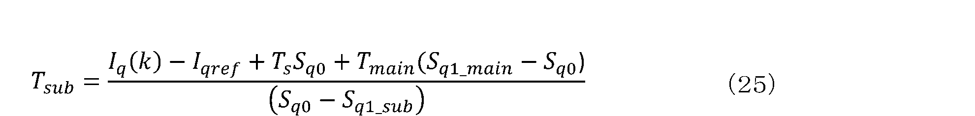
(23)式で求めたTmainを(25)式に代入し、サブベクトルの発生時間を求めることができる。以上より、メインベクトルとサブベクトルの発生時間を決定でき、制御周期で割ることで、メインベクトルとサブベクトルのデューティが求まる。そして、デューティの制限処理として、以下を実施する。求めたメインベクトルとサブベクトルのデューティが負の場合は0%に設定する。メインベクトルとサブベクトルのデューティの合計値は最大100%であり、合計値が100%以上の場合は、メインベクトルとサブベクトルのデューティをそれぞれ合計値で割ることで補正する。以上の制限処理を実施した場合はデューティが変更されるので、変更したデューティに制御周期を掛けて、TmainとTsubを再演算する。メインベクトルとサブベクトルのデューティを図9に基づき三相のデューティに振り分ければ、今回の電流指令に最も近づく1制御周期後のPWM波形を生成可能となる。 The generation time of the sub-vector can be obtained by substituting T main obtained by the formula (23) into the formula (25). From the above, the generation time of the main vector and the sub-vector can be determined, and the duties of the main vector and the sub-vector can be obtained by dividing by the control period. Then, the following is performed as a duty limiting process. If the obtained duties of the main vector and the sub-vector are negative, they are set to 0%. The total value of the duties of the main vector and the sub-vector is a maximum of 100%, and if the total value is 100% or more, the duties of the main vector and the sub-vector are corrected by dividing them by the total value. When the above limiting process is performed, the duty is changed, so the changed duty is multiplied by the control period to recalculate T main and T sub . If the duties of the main vector and the sub-vector are allocated to the three-phase duties based on FIG. 9, it is possible to generate a PWM waveform one control period later that is closest to the current command.
以降は、制御周期毎にモデル予測制御が繰り返される。言い換えれば、今回のPWM信号波形は前回のモデル予測制御の結果であり、前述した第1ステップで1制御周期後の次回予測電流を求める際には、第2実施形態の場合は、第1実施形態の(7)、(8)式とは異なり、電流変化率とベクトル発生時間の前回値が必要であるから(20)、(21)式で求める。 After that, model predictive control is repeated for each control cycle. In other words, the current PWM signal waveform is the result of the previous model predictive control, and when calculating the next predicted current one control cycle later in the first step described above, in the case of the second embodiment, unlike equations (7) and (8) in the first embodiment, the previous values of the current change rate and vector generation time are required, so they are calculated using equations (20) and (21).
また、第2実施形態では、位置推定演算用のd軸電圧Vdについても、スイッチングパターンの試行時とは最終的に出力する値が異なるので、次式で再計算が必要である。但し、相対変換の場合である。 In the second embodiment, the d-axis voltage Vd for position estimation calculation also has to be recalculated using the following formula since the final output value differs from that during trial switching patterns. However, this is the case for relative conversion.

図11にシミュレーション結果を示す。評価関数により決定したメインベクトルと、隣り合うどちらか一方のサブベクトルの発生時間を、電流指令値に予測電流が近付くように決定して、インバータが任意の電圧ベクトルを出力できるので、最適なスイッチングパターンを選択した上で、電流リプルを低減できる。 The simulation results are shown in Figure 11. The generation time of the main vector determined by the evaluation function and one of the adjacent sub-vectors is determined so that the predicted current approaches the current command value, allowing the inverter to output any voltage vector. This makes it possible to select the optimal switching pattern and reduce current ripple.
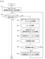
図12から図14は、第1、第2実施形態の制御を選択的に実行することを前提としたフローチャートである。先ず、ゼロベクトルの電流変化率Sd0、Sq0を(1)、(2)式で演算すると(S1)、ステップS3~S9の繰り返し処理において各スイッチングパターンの試行、評価を行う。試行するスイッチングパターンによる出力電圧Vu、Vv、Vwを演算し(S3)、それらの電圧より励磁電圧Vd、トルク電圧Vqを演算する(S4)。 12 to 14 are flow charts assuming that the control of the first and second embodiments is selectively executed. First, the current change rates Sd0 and Sq0 of the zero vector are calculated using the formulas (1) and (2) (S1), and then each switching pattern is tried and evaluated in the repeated processing of steps S3 to S9. The output voltages Vu, Vv, and Vw according to the switching pattern to be tried are calculated (S3), and the excitation voltage Vd and torque voltage Vq are calculated from these voltages (S4).
次に、有効ベクトルV1~V6の1つについて電流変化率Sd1、Sq1を(3)、(4)式で演算し(S5)、予測電流Id(k+1)、Iq(k+1)を(7)、(8)式で演算する(S6)。尚、第2実施形態の制御を行なうため各相のデューティ比Du、Dv、Dwを計算する際には、電流変化率Sd1、Sq1を記憶しておく。それから、評価関数gを(9)式で演算し(S7)、演算結果を比較して評価関数gの最小値を選択する(S8)。今回の演算結果が暫定的に最小であれば(YES)、対応するスイッチングパターン、Vd及びVq、予測電流Id(k+1)、Iq(k+1)を更新する(S9)。 Next, the current change rates Sd1 and Sq1 for one of the effective vectors V1 to V6 are calculated using equations (3) and (4) (S5), and the predicted currents Id (k+1) and Iq (k+1) are calculated using equations (7) and (8) (S6). When calculating the duty ratios Du, Dv, and Dw of each phase to perform the control of the second embodiment, the current change rates Sd1 and Sq1 are stored. Then, the evaluation function g is calculated using equation (9) (S7), and the calculation results are compared to select the minimum value of the evaluation function g (S8). If the current calculation result is provisionally minimum (YES), the corresponding switching pattern, Vd and Vq , and the predicted currents Id (k+1) and Iq (k+1) are updated (S9).
全てのスイッチングパターンを試行すると(S2;YES)、第1実施形態の制御を行なう場合は(S10;YES)、選択したスイッチングパターン;メインベクトルのデューティ比を100%に設定する(S11)。そして、選択したメインベクトルに応じて各相のデューティ比Du、Dv、Dwを設定すると(S23)、第1実施形態の制御を行なう場合は(S24;YES)そのまま処理を終了する。尚、第1、第2実施形態の何れの制御を行なうかは、ユーザの選択設定による。 After all switching patterns have been tried (S2; YES), if the control of the first embodiment is to be performed (S10; YES), the selected switching pattern; the duty ratio of the main vector is set to 100% (S11). Then, the duty ratios Du, Dv, and Dw of each phase are set according to the selected main vector (S23), and if the control of the first embodiment is to be performed (S24; YES), the process ends. Note that whether the control of the first or second embodiment is to be performed is determined by the user's selection setting.
一方、第2実施形態の制御を行なう場合は(S10;NO)、選択したメインベクトルに隣り合う2つのベクトルの一方をサブベクトルとして選択する(S12)。そして、メインベクトルの発生時間Tmain、サブベクトルの発生時間Tsubを、それぞれ(23)式、(25)式で演算し(S13、S14)、メインベクトル及びサブベクトルのデューティ比を演算する(S15)。サブベクトルのデューティ比が正の値であれば(S16;YES)サブベクトルの選択は適切であり、デューティ比の制限処理を行なって(S17)予測電流Id(k+1、Iq(k+1)を(20)式、(21)式により再演算する(S18)。それから、ステップS23に移行する。 On the other hand, when the control of the second embodiment is performed (S10; NO), one of the two vectors adjacent to the selected main vector is selected as a sub-vector (S12). Then, the generation time Tmain of the main vector and the generation time Tsub of the sub-vector are calculated using equations (23) and (25), respectively (S13, S14), and the duty ratios of the main vector and the sub-vector are calculated (S15). If the duty ratio of the sub-vector is a positive value (S16; YES), the selection of the sub-vector is appropriate, and the duty ratio is limited (S17), and the predicted currents Id (k+1, Iq (k+1) are recalculated using equations (20) and (21) (S18). Then, the process proceeds to step S23.
サブベクトルのデューティ比が負の値であれば(S16;NO)、メインベクトルに隣り合う2つのベクトルの他方をサブベクトルとして選択する(S19)。そして、ステップS13~S15と同様の処理を行なうと(S20~S22)、ステップS17に移行する。 If the duty ratio of the sub-vector is negative (S16; NO), the other of the two vectors adjacent to the main vector is selected as the sub-vector (S19). Then, the same processes as steps S13 to S15 are performed (S20 to S22), and the process proceeds to step S17.
また、図14に示す処理において、第2実施形態の制御を行なう場合は(S24;NO)、選択したサブベクトルに応じて各相のデューティ比Du、Dv、Dwを設定し(S25)、励磁電圧Vdを(26)式により再演算する(S26)。電圧Vdは位置センサレス制御に使用される。尚、トルク電圧Vqを共に求めても良いが、トルク電圧Vqは実際には未使用となる。 14, when the control of the second embodiment is performed (S24; NO), the duty ratios Du, Dv, and Dw of each phase are set according to the selected sub-vector (S25), and the excitation voltage Vd is recalculated by the formula (26) (S26). The voltage Vd is used for position sensorless control. The torque voltage Vq may also be calculated, but the torque voltage Vq is not actually used.
以上のように第2実施形態によれば、モデル予測制御部7は、電気角60度毎に設定される6つの空間電圧ベクトルから1つのスイッチングパターンをメインベクトルとして選択すると、そのメインベクトルに隣り合う2つの空間電圧ベクトルの一方をサブベクトルとして選択し、スイッチング周期内において、メインベクトル及びサブベクトルそれぞれの出力時間を調整する。これにより、第1実施形態の制御よりも、電流リプルをより低減できるようになる。
As described above, according to the second embodiment, the model
(その他の実施形態)
評価関数gについては(9)~(11)式に限ることなく、適宜適切な関数を選択すれば良い。
モータの負荷は、圧縮機に限らない。
本発明のいくつかの実施形態を説明したが、これらの実施形態は例として提示したものであり、発明の範囲を限定することは意図していない。これら新規な実施形態は、その他の様々な形態で実施されることが可能であり、発明の要旨を逸脱しない範囲で種々の省略、置き換え、変更を行うことができる。これらの実施形態やその変形は、発明の範囲や要旨に含まれると共に、特許請求の範囲に記載された発明とその均等の範囲に含まれる。
Other Embodiments
The evaluation function g is not limited to the formulas (9) to (11), and any appropriate function may be selected.
The load of the motor is not limited to the compressor.
Although some embodiments of the present invention have been described, these embodiments are presented as examples and are not intended to limit the scope of the invention. These novel embodiments can be implemented in various other forms, and various omissions, substitutions, and modifications can be made without departing from the spirit of the invention. These embodiments and their modifications are included in the scope and spirit of the invention, and are included in the scope of the invention and its equivalents described in the claims.
図面中、1はインバータ回路、2はモータ、3は電流検出部、4は座標変換部、5は位置推定部、6はq軸電流指令生成部、7はモデル予測制御部、10はモータ制御装置、21は空調機、22は圧縮機を示す。 In the drawing, 1 indicates an inverter circuit, 2 indicates a motor, 3 indicates a current detection unit, 4 indicates a coordinate conversion unit, 5 indicates a position estimation unit, 6 indicates a q-axis current command generation unit, 7 indicates a model prediction control unit, 10 indicates a motor control device, 21 indicates an air conditioner, and 22 indicates a compressor.
Claims (6)
前記モータの巻線に流れる電流を検出する電流検出部と、
前記電流供給部が出力する電圧と前記電流とに基づいて、前記モータの回転速度及び電気角を推定する速度・電気角推定部と、
前記電流と前記電気角とに基づいて、励磁電流及びトルク電流を得る座標変換部と、
永久磁石同期モータのベクトル制御座標のトルク式に基づき算出されるトルク成分電流指令値に、機械系の運動方程式に基づき算出した予測トルクを代入することで、入力される速度指令と推定された速度との差分をゼロに近付けるトルク成分電流指令値を生成するトルク電流指令決定部と、
前記電力供給部が出力可能な、空間電圧ベクトルに基づく複数のスイッチングパターンのそれぞれに応じて決まる電流変化率を含む複数の予測電流に対し、前記トルク成分電流指令値及び外部より入力される励磁成分電流指令値それぞれに対応する予測電流との差の大きさを評価する評価関数を適用することで、スイッチングパターンを選択して出力するモデル予測制御部とを備えるモータ制御装置。 a power supply unit that supplies AC power to a motor that drives a load;
a current detection unit that detects a current flowing through a winding of the motor;
a speed/electrical angle estimating unit that estimates a rotation speed and an electrical angle of the motor based on the voltage output by the current supplying unit and the current;
a coordinate conversion unit that obtains an excitation current and a torque current based on the current and the electrical angle;
a torque current command determination unit that generates a torque component current command value that brings a difference between an input speed command and an estimated speed closer to zero by substituting a predicted torque calculated based on an equation of motion of a mechanical system into a torque component current command value calculated based on a torque equation of a vector control coordinate of a permanent magnet synchronous motor;
a model predictive control unit that selects and outputs a switching pattern by applying an evaluation function that evaluates the magnitude of a difference between a plurality of predicted currents including a current change rate determined according to each of a plurality of switching patterns based on a space voltage vector that can be output by the power supply unit and a predicted current corresponding to each of the torque component current command values and an excitation component current command value input from an external source.
スイッチング周期内において、前記メインベクトル及び前記サブベクトルそれぞれの出力時間を調整する請求項1記載のモータ制御装置。 the model predictive control unit selects one switching pattern as a main vector from six space voltage vectors set for every 60 electrical degrees, and selects one of two space voltage vectors adjacent to the main vector as a sub-vector;
2. The motor control device according to claim 1, wherein the output times of the main vector and the sub-vectors are adjusted within a switching period.
この圧縮機を駆動するモータと、
請求項1から5の何れか一項に記載のモータ制御装置とを備える空調機。 A compressor;
A motor that drives the compressor;
An air conditioner comprising the motor control device according to any one of claims 1 to 5.
Priority Applications (4)
| Application Number | Priority Date | Filing Date | Title |
|---|---|---|---|
| JP2021129010A JP7558905B2 (en) | 2021-08-05 | 2021-08-05 | Motor control device and air conditioner |
| CN202210498568.5A CN115706548A (en) | 2021-08-05 | 2022-05-09 | Motor control device and air conditioner |
| EP22172966.8A EP4131769B1 (en) | 2021-08-05 | 2022-05-12 | Motor control device and air conditioner |
| US17/663,876 US11658596B2 (en) | 2021-08-05 | 2022-05-18 | Motor control device and air conditioner |
Applications Claiming Priority (1)
| Application Number | Priority Date | Filing Date | Title |
|---|---|---|---|
| JP2021129010A JP7558905B2 (en) | 2021-08-05 | 2021-08-05 | Motor control device and air conditioner |
Publications (2)
| Publication Number | Publication Date |
|---|---|
| JP2023023452A JP2023023452A (en) | 2023-02-16 |
| JP7558905B2 true JP7558905B2 (en) | 2024-10-01 |
Family
ID=81648052
Family Applications (1)
| Application Number | Title | Priority Date | Filing Date |
|---|---|---|---|
| JP2021129010A Active JP7558905B2 (en) | 2021-08-05 | 2021-08-05 | Motor control device and air conditioner |
Country Status (4)
| Country | Link |
|---|---|
| US (1) | US11658596B2 (en) |
| EP (1) | EP4131769B1 (en) |
| JP (1) | JP7558905B2 (en) |
| CN (1) | CN115706548A (en) |
Families Citing this family (2)
| Publication number | Priority date | Publication date | Assignee | Title |
|---|---|---|---|---|
| JP7568832B2 (en) * | 2021-03-26 | 2024-10-16 | ファナック株式会社 | Synchronous Motor Controller |
| WO2024171881A1 (en) | 2023-02-17 | 2024-08-22 | 三菱瓦斯化学株式会社 | Compound, composition, molded article, and production method |
Citations (1)
| Publication number | Priority date | Publication date | Assignee | Title |
|---|---|---|---|---|
| US20200389108A1 (en) | 2019-06-10 | 2020-12-10 | Black & Decker Inc. | Field-oriented sensorless brushless motor control in a power tool |
Family Cites Families (15)
| Publication number | Priority date | Publication date | Assignee | Title |
|---|---|---|---|---|
| US6411052B1 (en) * | 1999-09-17 | 2002-06-25 | Delphi Technologies, Inc. | Method and apparatus to compensate for resistance variations in electric motors |
| KR100484819B1 (en) * | 2002-10-10 | 2005-04-22 | 엘지전자 주식회사 | Controlling System of Synchronous Reluctance Motoe |
| JP5127377B2 (en) * | 2007-09-14 | 2013-01-23 | 株式会社東芝 | Permanent magnet drive system |
| JP4691150B2 (en) * | 2008-10-10 | 2011-06-01 | 株式会社東芝 | Motor control device, motor control method, and air conditioner |
| JP5175887B2 (en) | 2010-03-23 | 2013-04-03 | 株式会社東芝 | Motor control device and electrical equipment |
| JP5678837B2 (en) * | 2011-08-09 | 2015-03-04 | 株式会社デンソー | Rotating machine control device |
| KR101898755B1 (en) * | 2011-08-18 | 2018-09-13 | 히다찌 겐끼 가부시키가이샤 | Motor control device and work machine using same |
| US9444382B2 (en) * | 2013-01-30 | 2016-09-13 | Infineon Technologies Ag | Optimized field oriented control strategies for permanent magnet synchronous motors |
| US9281772B2 (en) * | 2014-06-26 | 2016-03-08 | Toshiba Mitsubishi-Electric Industrial Systems Corporation | Controller for power converter |
| JP6364463B2 (en) * | 2016-09-26 | 2018-07-25 | 日立ジョンソンコントロールズ空調株式会社 | Motor driving apparatus, refrigeration cycle apparatus including the same, and motor driving method |
| JP2018093572A (en) | 2016-11-30 | 2018-06-14 | アイシン精機株式会社 | Motor control device |
| CN107612446B (en) * | 2017-11-03 | 2020-06-02 | 天津工业大学 | A Model Predictive Torque Control Method for Built-in Permanent Magnet Synchronous Motors |
| CN109617481A (en) * | 2018-12-25 | 2019-04-12 | 南京越博电驱动系统有限公司 | A kind of permanent magnet synchronous motor prediction method for controlling torque |
| CN110336501B (en) * | 2019-07-10 | 2020-10-23 | 河北工业大学 | A Model Predictive Control Method for Embedded Permanent Magnet Synchronous Motors |
| JP7272188B2 (en) * | 2019-09-03 | 2023-05-12 | 株式会社デンソー | Rotating electric machine controller and program |
-
2021
- 2021-08-05 JP JP2021129010A patent/JP7558905B2/en active Active
-
2022
- 2022-05-09 CN CN202210498568.5A patent/CN115706548A/en active Pending
- 2022-05-12 EP EP22172966.8A patent/EP4131769B1/en active Active
- 2022-05-18 US US17/663,876 patent/US11658596B2/en active Active
Patent Citations (1)
| Publication number | Priority date | Publication date | Assignee | Title |
|---|---|---|---|---|
| US20200389108A1 (en) | 2019-06-10 | 2020-12-10 | Black & Decker Inc. | Field-oriented sensorless brushless motor control in a power tool |
Also Published As
| Publication number | Publication date |
|---|---|
| CN115706548A (en) | 2023-02-17 |
| EP4131769A1 (en) | 2023-02-08 |
| EP4131769B1 (en) | 2025-04-30 |
| US11658596B2 (en) | 2023-05-23 |
| JP2023023452A (en) | 2023-02-16 |
| US20230045429A1 (en) | 2023-02-09 |
Similar Documents
| Publication | Publication Date | Title |
|---|---|---|
| JP6165470B2 (en) | Motor control device, heat pump system and air conditioner | |
| KR101238957B1 (en) | Motor control device and electric equipment | |
| US9287820B2 (en) | Motor control device and air conditioner | |
| JP2012005199A (en) | Motor controller, compressor and heat pump device | |
| JP7558905B2 (en) | Motor control device and air conditioner | |
| WO2017022083A1 (en) | Synchronous motor control device, compressor drive device, air-conditioner, and method for controlling synchronous motor | |
| WO2016143608A1 (en) | Motor control apparatus, heat pump system, and air conditioner | |
| Huang et al. | Torque and current control of induction motor drives for inverter switching frequency reduction | |
| JP2010130844A (en) | Driving device for compressor motor and method of controlling inverter | |
| JP7237746B2 (en) | Open winding motor drive device and refrigeration cycle device | |
| JP2008295204A (en) | Motor control device and motor control method | |
| JP2018182975A (en) | Compressor motor drive | |
| JP6593685B2 (en) | Motor control device and generator control device | |
| JP4578500B2 (en) | Inverter control device and refrigeration air conditioner | |
| JP5857689B2 (en) | Rotating machine control device | |
| JP4581603B2 (en) | Electric motor drive | |
| JP6647448B2 (en) | Inverter control device and inverter control method | |
| JP2009296722A (en) | Motor controller, motor control method, and air conditioner | |
| JP2003274666A (en) | Inverter device and method for controlling the same | |
| JP6490540B2 (en) | Rotation position detection device, air conditioner, and rotation position detection method | |
| JP7182478B2 (en) | power converter | |
| JP5891964B2 (en) | Rotating machine control device | |
| JP7467301B2 (en) | Open winding motor drive device and refrigeration cycle device | |
| WO2021095349A1 (en) | Electric motor drive control device and method, and electric motor drive control system | |
| JP7361948B2 (en) | Electric motor drive equipment, refrigeration cycle equipment, and air conditioners |
Legal Events
| Date | Code | Title | Description |
|---|---|---|---|
| A621 | Written request for application examination |
Free format text: JAPANESE INTERMEDIATE CODE: A621 Effective date: 20240208 |
|
| TRDD | Decision of grant or rejection written | ||
| A977 | Report on retrieval |
Free format text: JAPANESE INTERMEDIATE CODE: A971007 Effective date: 20240807 |
|
| A01 | Written decision to grant a patent or to grant a registration (utility model) |
Free format text: JAPANESE INTERMEDIATE CODE: A01 Effective date: 20240820 |
|
| A61 | First payment of annual fees (during grant procedure) |
Free format text: JAPANESE INTERMEDIATE CODE: A61 Effective date: 20240918 |
|
| R150 | Certificate of patent or registration of utility model |
Ref document number: 7558905 Country of ref document: JP Free format text: JAPANESE INTERMEDIATE CODE: R150 |