JP7549941B2 - Driving assistance device and driving assistance method - Google Patents
Driving assistance device and driving assistance method Download PDFInfo
- Publication number
- JP7549941B2 JP7549941B2 JP2021044032A JP2021044032A JP7549941B2 JP 7549941 B2 JP7549941 B2 JP 7549941B2 JP 2021044032 A JP2021044032 A JP 2021044032A JP 2021044032 A JP2021044032 A JP 2021044032A JP 7549941 B2 JP7549941 B2 JP 7549941B2
- Authority
- JP
- Japan
- Prior art keywords
- vehicle
- driving force
- obstacle
- collision avoidance
- vehicle speed
- Prior art date
- Legal status (The legal status is an assumption and is not a legal conclusion. Google has not performed a legal analysis and makes no representation as to the accuracy of the status listed.)
- Active
Links
- 238000000034 method Methods 0.000 title claims description 19
- 230000009467 reduction Effects 0.000 claims description 49
- 238000001514 detection method Methods 0.000 claims description 41
- 230000007423 decrease Effects 0.000 claims description 10
- 238000013459 approach Methods 0.000 claims description 7
- 230000003247 decreasing effect Effects 0.000 claims description 7
- 238000010586 diagram Methods 0.000 description 33
- 230000001133 acceleration Effects 0.000 description 27
- 230000010365 information processing Effects 0.000 description 9
- 230000006870 function Effects 0.000 description 8
- 238000005259 measurement Methods 0.000 description 8
- 238000012545 processing Methods 0.000 description 7
- 230000005540 biological transmission Effects 0.000 description 4
- 230000008569 process Effects 0.000 description 4
- 230000005856 abnormality Effects 0.000 description 2
- 230000001629 suppression Effects 0.000 description 2
- 238000012986 modification Methods 0.000 description 1
- 230000004048 modification Effects 0.000 description 1
- 238000012544 monitoring process Methods 0.000 description 1
- 230000007935 neutral effect Effects 0.000 description 1
- 230000003287 optical effect Effects 0.000 description 1
- 230000004044 response Effects 0.000 description 1
- 239000004065 semiconductor Substances 0.000 description 1
- 238000006467 substitution reaction Methods 0.000 description 1
- 230000007704 transition Effects 0.000 description 1
- 230000003313 weakening effect Effects 0.000 description 1
Images


Classifications
-
- B—PERFORMING OPERATIONS; TRANSPORTING
- B60—VEHICLES IN GENERAL
- B60W—CONJOINT CONTROL OF VEHICLE SUB-UNITS OF DIFFERENT TYPE OR DIFFERENT FUNCTION; CONTROL SYSTEMS SPECIALLY ADAPTED FOR HYBRID VEHICLES; ROAD VEHICLE DRIVE CONTROL SYSTEMS FOR PURPOSES NOT RELATED TO THE CONTROL OF A PARTICULAR SUB-UNIT
- B60W30/00—Purposes of road vehicle drive control systems not related to the control of a particular sub-unit, e.g. of systems using conjoint control of vehicle sub-units
- B60W30/08—Active safety systems predicting or avoiding probable or impending collision or attempting to minimise its consequences
- B60W30/09—Taking automatic action to avoid collision, e.g. braking and steering
-
- B—PERFORMING OPERATIONS; TRANSPORTING
- B60—VEHICLES IN GENERAL
- B60W—CONJOINT CONTROL OF VEHICLE SUB-UNITS OF DIFFERENT TYPE OR DIFFERENT FUNCTION; CONTROL SYSTEMS SPECIALLY ADAPTED FOR HYBRID VEHICLES; ROAD VEHICLE DRIVE CONTROL SYSTEMS FOR PURPOSES NOT RELATED TO THE CONTROL OF A PARTICULAR SUB-UNIT
- B60W2520/00—Input parameters relating to overall vehicle dynamics
- B60W2520/10—Longitudinal speed
-
- B—PERFORMING OPERATIONS; TRANSPORTING
- B60—VEHICLES IN GENERAL
- B60W—CONJOINT CONTROL OF VEHICLE SUB-UNITS OF DIFFERENT TYPE OR DIFFERENT FUNCTION; CONTROL SYSTEMS SPECIALLY ADAPTED FOR HYBRID VEHICLES; ROAD VEHICLE DRIVE CONTROL SYSTEMS FOR PURPOSES NOT RELATED TO THE CONTROL OF A PARTICULAR SUB-UNIT
- B60W2540/00—Input parameters relating to occupants
- B60W2540/10—Accelerator pedal position
-
- B—PERFORMING OPERATIONS; TRANSPORTING
- B60—VEHICLES IN GENERAL
- B60W—CONJOINT CONTROL OF VEHICLE SUB-UNITS OF DIFFERENT TYPE OR DIFFERENT FUNCTION; CONTROL SYSTEMS SPECIALLY ADAPTED FOR HYBRID VEHICLES; ROAD VEHICLE DRIVE CONTROL SYSTEMS FOR PURPOSES NOT RELATED TO THE CONTROL OF A PARTICULAR SUB-UNIT
- B60W2552/00—Input parameters relating to infrastructure
- B60W2552/50—Barriers
-
- B—PERFORMING OPERATIONS; TRANSPORTING
- B60—VEHICLES IN GENERAL
- B60W—CONJOINT CONTROL OF VEHICLE SUB-UNITS OF DIFFERENT TYPE OR DIFFERENT FUNCTION; CONTROL SYSTEMS SPECIALLY ADAPTED FOR HYBRID VEHICLES; ROAD VEHICLE DRIVE CONTROL SYSTEMS FOR PURPOSES NOT RELATED TO THE CONTROL OF A PARTICULAR SUB-UNIT
- B60W2554/00—Input parameters relating to objects
- B60W2554/80—Spatial relation or speed relative to objects
- B60W2554/802—Longitudinal distance
-
- B—PERFORMING OPERATIONS; TRANSPORTING
- B60—VEHICLES IN GENERAL
- B60W—CONJOINT CONTROL OF VEHICLE SUB-UNITS OF DIFFERENT TYPE OR DIFFERENT FUNCTION; CONTROL SYSTEMS SPECIALLY ADAPTED FOR HYBRID VEHICLES; ROAD VEHICLE DRIVE CONTROL SYSTEMS FOR PURPOSES NOT RELATED TO THE CONTROL OF A PARTICULAR SUB-UNIT
- B60W2720/00—Output or target parameters relating to overall vehicle dynamics
- B60W2720/10—Longitudinal speed
Landscapes
- Engineering & Computer Science (AREA)
- Automation & Control Theory (AREA)
- Transportation (AREA)
- Mechanical Engineering (AREA)
- Control Of Driving Devices And Active Controlling Of Vehicle (AREA)
- Traffic Control Systems (AREA)
Description
本開示は、運転支援装置および運転支援方法に関する。 This disclosure relates to a driving assistance device and a driving assistance method.
従来、車両周辺の障害物との衝突を回避する衝突回避制御が知られている。また、衝突回避制御において、路面状態に応じて駆動力を調整する技術が開示されている。 Conventionally, collision avoidance control is known for avoiding collisions with obstacles around the vehicle. In addition, technology has been disclosed for adjusting the driving force in accordance with road surface conditions in collision avoidance control.
例えば、障害物を検出した場合に車両の加速を制限し、障害物と車両との間に段差がある場合には加速制限を徐々に緩めて段差を乗り越え、乗り越え後に再び加速制限を実行する技術が開示されている。 For example, a technology has been disclosed that limits the vehicle's acceleration when an obstacle is detected, and if there is a step between the obstacle and the vehicle, gradually relaxes the acceleration limit to allow the vehicle to overcome the step, and then applies the acceleration limit again after the step has been overcome.
しかし、従来技術では、段差などの対象物を乗り越えた後の障害物までの距離によって、加速制限がきつすぎて障害物に十分に接近できなくなる場合や、加速制限が緩すぎて障害物へ接触してしまう場合があった。このため、従来技術では、良好な車両走行支援を行うことが困難な場合があった。 However, with conventional technology, depending on the distance to an obstacle after going over an obstacle such as a step, the acceleration limit may be too strict, making it impossible to get close to the obstacle, or it may be too lenient, causing contact with the obstacle. For this reason, with conventional technology, it may be difficult to provide good vehicle driving assistance.
本開示が解決しようとする課題は、良好な車両走行支援を行うことができる、運転支援装置および運転支援方法を提供することである。 The problem that this disclosure aims to solve is to provide a driving assistance device and a driving assistance method that can provide good vehicle driving assistance.
本開示にかかる運転支援装置は、検出部と、衝突回避制御部と、算出部と、駆動力制御部と、を備える。検出部は、車両の進行方向の障害物を検出する。衝突回避制御部は、前記障害物が検出された場合に、前記車両の駆動力を制御して前記障害物への衝突回避制御を行う。算出部は、前記衝突回避制御が開始された前記車両と前記障害物との間に存在する対象物を乗り越えたときの前記車両と前記障害物との距離に応じて、前記車両が前記対象物を乗り越えたときの駆動力の引き下げ量を算出する。駆動力制御部は、前記車両が前記対象物を乗り越えるときに、前記車両の車速が設定車速に到達するまで、運転者が操作したアクセルペダルのアクセル開度から定まる要求駆動力より小さい駆動力である初期駆動力から駆動力を徐々に引き上げ、前記車両の車速が設定車速に到達した後、駆動力を前記引き下げ量引き下げるように前記衝突回避制御部を制御する。前記算出部は、前記距離が短いほど大きい前記引き下げ量を算出する。 The driving assistance device according to the present disclosure includes a detection unit, a collision avoidance control unit, a calculation unit, and a driving force control unit. The detection unit detects an obstacle in the traveling direction of the vehicle. When the obstacle is detected, the collision avoidance control unit controls the driving force of the vehicle to perform collision avoidance control for the obstacle. The calculation unit calculates a reduction amount of the driving force when the vehicle passes over the object existing between the vehicle and the obstacle when the collision avoidance control is started, according to a distance between the vehicle and the obstacle when the vehicle passes over the object. The driving force control unit controls the collision avoidance control unit so that when the vehicle passes over the object, the driving force is gradually increased from an initial driving force, which is a driving force smaller than a required driving force determined from an accelerator opening of an accelerator pedal operated by a driver, until the vehicle speed of the vehicle reaches a set vehicle speed, and the driving force is reduced by the reduction amount after the vehicle speed of the vehicle reaches the set vehicle speed. The calculation unit calculates the reduction amount to be larger as the distance is shorter.
本開示にかかる運転支援装置および運転支援方法によれば、良好な車両走行支援を行うことができる。 The driving assistance device and driving assistance method disclosed herein can provide excellent vehicle driving assistance.
以下に添付図面を参照して、本開示に係る運転支援装置および運転支援方法の実施形態について説明する。 Below, an embodiment of the driving assistance device and driving assistance method according to the present disclosure will be described with reference to the attached drawings.
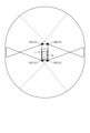
図1は、本実施形態の運転支援装置10を搭載した車両1の一例の模式図である。
Figure 1 is a schematic diagram of an example of a
運転支援装置10は、車両1の周辺の検知結果情報を用いて、障害物に対する衝突回避制御を行う情報処理装置である。本実施形態では、運転支援装置10は、車両1に搭載された形態を一例として説明する。
The
車両1には、複数のセンサ12が設けられている。センサ12は、車両1の周辺の物体を検知するセンサである。本実施形態では、センサ12は、例えば、数cm~数mの検知距離であり、比較的近距離の物体の有無および物体までの距離を検知可能である。本実施形態では、センサ12が、超音波センサである形態を一例として説明する。超音波センサは、20kHz~100kHzの超音波を送信波として照射する照射機能と、物体で反射した超音波を反射波として受信する受信機能と、を有する。
The
本実施形態では、車両1は、センサ12として、センサ12A~センサ12Dを備える。センサ12Aおよびセンサ12Bは、車両1の車幅方向に直交する全長方向の一方に設けられている。具体的には、センサ12Aおよびセンサ12Bは、例えば、車両1のフロントバンパー部分に設けられている。センサ12Cおよびセンサ12Dは、車両1の全長方向の他方に設けられている。センサ12Cおよびセンサ12Dは、例えば、車両1のリアバンパーに設けられている。
In this embodiment, the
なお、車両1に設けられるセンサ12の個数および配置は、上記形態に限定されるものではない。例えば、車両1のフロント部分に1個または3個以上、車両1のリア部分に1個または3個以上、車両1のサイド部分に1個以上、のセンサ12を設けた構成であってもよい。
The number and arrangement of the
センサ12A~センサ12Dの各々は、各々の検知範囲において物体を検知し、物体の検知情報を運転支援装置10へ出力する。
Each of
次に、車両1の機能的構成について詳細に説明する。
Next, the functional configuration of
図2は、車両1の機能的構成のブロック図である。車両1は、センサ12と、センサECU(Engine Control Unit)14と、Gセンサ16と、舵角センサ18と、走行制御部20と、操作部22と、メータコンピュータ24と、記憶部26と、運転支援装置10と、を備える。
Figure 2 is a block diagram of the functional configuration of the
センサECU14、Gセンサ16、舵角センサ18、走行制御部20、メータコンピュータ24、記憶部26、および運転支援装置10は、バス29を介して通信可能に接続されている。走行制御部20は、操作部22および運転支援装置10と通信可能に接続されている。
The
センサECU14は、センサ12と通信可能に接続されている。センサECU14は、物体の検知情報をセンサ12から受信する。センサECU14は、検知情報から、物体までの距離を算出し、算出した距離の情報を含む検知結果情報を、運転支援装置10へ出力する。物体までの距離は、物標距離、と称される場合がある。
The
センサECU14は、センサ12から照射された超音波が物体で反射し、反射波が戻るまでの時間を計測することによって、物体までの距離を測定する。なお、センサ12の検知角度が例えば90°などの広範囲の場合には、単一のセンサ12による検知情報のみでは物体の方向がわからない。このため、センサECU14は、複数のセンサ12によって検知された物体までの距離の情報を用いて、物体の位置を特定する。物体の位置は、例えば、車両1からの距離および方向によって表される。また、センサECU14は、複数のセンサ12による検知情報を用いることで、検知された物体が壁のような形状なのか電柱のような形状なのか、などの形状も判断することができる。
The
本実施形態では、センサECU14は、センサ12によって検知された物体の物体情報と、物体までの距離を表す距離情報と、を含む検知結果情報を、運転支援装置10へ出力する。
In this embodiment, the
物体とは、センサ12によって検知可能な物である。すなわち、本実施形態では、物体とは、センサ12から照射された超音波を反射し、反射波の生じる物である。本実施形態では、物体には、障害物および対象物が含まれる。
An object is something that can be detected by the
障害物とは、車両1が乗り越えて走行することの困難な物体である。また、障害物とは、車両1が接触を回避する対象の物体である。例えば、障害物は、壁、電柱、などであるが、これらに限定されない。
An obstacle is an object that is difficult for
対象物とは、車両1が乗り越えて走行することの可能な物体である。例えば、対象物は、段差、縁石、フラップ、などであるが、これらに限定されない。
An object is an object that
物体情報は、検知された物体が障害物であることを表す障害物情報、および、検知された物体が対象物であることを表す対象物情報、の少なくとも一方を含む。 The object information includes at least one of obstacle information indicating that the detected object is an obstacle, and object information indicating that the detected object is a target object.
センサECU14は、障害物の形状や高さなどの特長を表す障害物特徴情報を予め記憶する。また、センサECU14は、車両1の車高などに応じて、段差などである対象物の形状や高さなどの特長を表す対象物特徴情報を予め記憶する。そして、センサECU14は、センサ12による検知情報によって特定される物体の形状情報に対応する障害物特徴情報または対象物特徴情報を検索する。これらの処理により、センサECU14は、センサ12によって検知された物体が障害物であるか対象物であるかを特定すればよい。
The
そして、センサECU14は、物体の物体情報と、物体までの距離を表す距離情報と、を含む検知結果情報を、運転支援装置10へ出力すればよい。なお、センサECU14による処理の少なくとも一部は、運転支援装置10またはセンサ12で実行してもよい。
Then, the
Gセンサ16は、車両1の加速度を計測し、測定結果を運転支援装置10へ出力する。本実施形態では、Gセンサ16は、車両1の前後方向の加速度、および、車両1の上下方向の加速度、の各々の計測結果を、運転支援装置10へ出力する形態を一例として説明する。前後方向は、車両1の車幅方向に直交する全長方向に一致する。車両1の上下方向は、車両1の車幅方向および全長方向の双方に直交する方向である。例えば、車両1の上下方向は、車両1の車幅方向および全長方向によって形成される面が水平面と一致する場合、鉛直方向に一致する。
The
Gセンサ16は、車両1の車輪速度から算出される加速度と、車両1の走行する路面の傾斜である車両1の傾きによる重力加速度と、の合計値を、車両1の前後方向の加速度の計測結果情報として運転支援装置10へ出力する。
The
舵角センサ18は、車両1に設けられたステアリングホイールの操舵角を検出し、舵角情報として運転支援装置10へ出力する。
The
走行制御部20は、車両1の走行を制御するECUである。走行制御部20は、エンジンECU20Aと、ブレーキECU20Bと、を含む。
The driving
エンジンECU20Aは、車両1のエンジンやモータ等の駆動装置の制御、および、車両1のトランスミッション等の伝達系装置の制御を実行する。例えば、エンジンECU20Aは、車両1に設けられたスロットルアクチュエータやトランスミッションギアの制御を行う。また、エンジンECU20Aは、アクセルペダル22Aの駆動を通じて運転者に情報を伝達するアクセルアクチュエータの制御を行う。
The
また、エンジンECU20Aは、操作部22と通信可能に接続されている。エンジンECU20Aは、操作部22から受付けたユーザによる操作情報を運転支援装置10へ送信する。
The
操作部22は、ユーザである運転者によって操作される。操作部22は、例えば、アクセルペダル22A、ブレーキペダル22B、シフトレバー22Cなどを含む。なお、車両1に搭載された操作部22は、これらに限定されない。
The
エンジンECU20Aは、アクセルペダル22Aのアクセルペダル操作情報、および、シフトレバー22Cのシフト位置情報、を含む操作情報を、運転支援装置10へ出力する。
The
アクセルペダル操作情報とは、アクセルペダル22Aの操作状態を表す情報であり、アクセルペダル22Aのアクセル開度を表す情報である。アクセル開度は、例えば、アクセルペダル22Aに接続された開度率センサによって検出される。
The accelerator pedal operation information is information that indicates the operation state of the
シフト位置情報は、シフトレバー22Cの位置を表す情報である。シフト位置情報は、例えば、駐車、後退、ニュートラル、通常走行、などのシフト位置を表す情報である。なお、シフト位置情報は、車両1の走行モードおよびコントロール状態を表す情報を更に含んでいてもよい。例えば、シフト位置情報は、スポーツモード、スノーモードなどの走行モード、および、クルーズコントロールの使用状況、などの情報を含んでいてもよい。
The shift position information is information that indicates the position of the
ブレーキECU20Bは、車両1の制動系の制御を行う。例えば、ブレーキECU20Bは、車両1の車輪に配置された油圧式ブレーキ装置を作動させるブレーキアクチュエータの制御を行う。また、ブレーキECU20Bは、ブレーキペダル22Bの駆動を通じて運転者に情報を伝達するために、ブレーキアクチュエータの制御を行う。ブレーキECU20Bは、運転支援装置10に対して、ブレーキペダル22Bの操作情報、および、車両1の車輪速度の情報を出力する。車輪速度の情報は、例えば、車両1の各車輪の各々に備えられた車輪速センサからの信号である。車輪速度とは、車両1の車輪の回転速度である。
The
メータコンピュータ24は、運転者に対する情報報知機能を備える。情報報知機能は、情報を表示する表示機能、情報を表す音を出力する音出力機能、などである。表示機能は、例えば運転者に対して表示による報知を行うコンビネーションメータ装置である。音出力機能は、例えば、ブザーや音声による報知を行う報知音発生装置である。
The
記憶部26は、各種のデータを記憶する。記憶部26は、例えば、RAM(Random Access Memory)、フラッシュメモリ等の半導体メモリ素子、ハードディスク、光ディスク等である。なお、記憶部26は、記憶媒体であってもよい。具体的には、記憶媒体は、プログラムまたは各種の情報を、LAN(Local Area Network)およびインターネットなどを介してダウンロードして記憶または一時記憶したものであってもよい。また、記憶部26を、複数の記憶媒体から構成してもよい。
The
次に、運転支援装置10について詳細に説明する。
Next, the driving
図3は、運転支援装置10のハードウェア構成図の一例である。
Figure 3 is an example of a hardware configuration diagram of the driving
運転支援装置10は、CPU(Central Processing Unit)11A、ROM(Read Only Memory)11B、RAM11C、およびI/F11D等がバス11Eにより相互に接続されており、通常のコンピュータを利用したハードウェア構成となっている。
The driving
CPU11Aは、本実施形態の運転支援装置10を制御する演算装置である。ROM11Bは、CPU11Aによる各種の処理を実現するプログラム等を記憶する。RAM11Cは、CPU11Aによる各種の処理に必要なデータを記憶する。I/F11Dは、データを送受信するためのインターフェースである。
The CPU 11A is a calculation device that controls the driving
本実施形態の運転支援装置10で実行される情報処理を実行するためのプログラムは、ROM11B等に予め組み込んで提供される。なお、本実施形態の運転支援装置10で実行されるプログラムは、運転支援装置10にインストール可能な形式又は実行可能な形式のファイルでCD-ROM、フレキシブルディスク(FD)、CD-R、DVD(Digital Versatile Disk)等のコンピュータで読み取り可能な記録媒体に記録されて提供するように構成してもよい。
The program for executing the information processing executed by the driving
図2に戻り説明を続ける。 Let's return to Figure 2 and continue the explanation.
運転支援装置10は、処理部30を備える。処理部30は、各種の情報処理を実行する。例えば、CPU11Aが、ROM11BからプログラムをRAM11C上に読み出して実行することにより、処理部30の後述する各機能部がコンピュータ上で実現される。プログラムは、例えば、ICS(Intelligent Clarence Sonar)アプリケーションに実装されたプログラムなどであるが、これに限定されない。ICSアプリケーションとは、運転支援装置10で動作するソフトウェアの一例である。
The driving
処理部30は、受付部30Aと、検出部30Bと、衝突回避制御部30Cと、対象物判定部30Dと、算出部30Eと、駆動力制御部30Fと、を備える。受付部30A、検出部30B、衝突回避制御部30C、対象物判定部30D、算出部30E、および、駆動力制御部30F、の一部または全ては、例えば、CPU11Aなどの処理装置にプログラムを実行させること、すなわち、ソフトウェアにより実現してもよいし、IC(Integrated Circuit)などのハードウェアにより実現してもよいし、ソフトウェアおよびハードウェアを併用して実現してもよい。また、受付部30A、検出部30B、衝突回避制御部30C、対象物判定部30D、算出部30E、および、駆動力制御部30Fの少なくとも1つを、ネットワークなどを介して運転支援装置10と通信可能に接続された外部の情報処理装置に搭載した構成としてもよい。
The
受付部30Aは、センサECU14、Gセンサ16、舵角センサ18、エンジンECU20A、およびブレーキECU20B、の各々から各種の情報を受付ける。
The reception unit 30A receives various information from each of the
本実施形態では、受付部30Aは、センサECU14から検知結果情報を受付ける。また、受付部30Aは、Gセンサ16から車両1の加速度の計測結果情報を受付ける。また、受付部30Aは、舵角センサ18から、舵角情報を受付ける。また、受付部30Aは、エンジンECU20Aから、アクセルペダル22Aのアクセルペダル操作情報、および、シフトレバー22Cのシフト位置情報、を含む操作情報を受付ける。また、受付部30Aは、ブレーキECU20Bから、ブレーキペダル22Bの操作情報、および、車両1の車輪速度の情報を受付ける。
In this embodiment, the reception unit 30A receives detection result information from the
検出部30Bは、車両1の進行方向の障害物を検出する。例えば、検出部30Bは、Gセンサ16によって検出された加速度の方向などから、車両1の進行方向を特定する。そして、例えば、検出部30Bは、受付部30AでセンサECU14から受付けた検知結果情報に含まれる物体情報に、特定した進行方向に存在する障害物を示す障害物情報が含まれるか否かを判断する。物体情報に、検知された物体が障害物であることを表す障害物情報が含まれる場合、検出部30Bは、車両1の進行方向の障害物を検出する。すなわち、検出部30Bは、車両1の進行方向に障害物が存在することを検出する。
The detection unit 30B detects an obstacle in the traveling direction of the
衝突回避制御部30Cは、障害物が検出された場合に、車両1の駆動力を制御して障害物への衝突回避制御を行う。衝突回避制御とは、運転者が操作したアクセルペダル22Aのアクセル開度から定まる要求駆動力より小さい駆動力に、車両1の駆動力を制限する制御である。
When an obstacle is detected, the collision avoidance control unit 30C controls the driving force of the
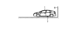
図4Aおよび図4Bは、衝突回避制御の一例の説明図である。図4Aは、車両1と障害物Bとの位置関係の一例の説明図である。例えば、車両1が進行方向Xに走行しており、この進行方向Xの下流側に障害物Bが存在する場面を想定する。車両1の検出部30Bが障害物Bを検出すると、衝突回避制御部30Cは、障害物Bへの衝突回避制御を実行する。衝突回避制御部30Cは、車両1の駆動力を制御することで、衝突回避制御を実行する。
Figures 4A and 4B are explanatory diagrams of an example of collision avoidance control. Figure 4A is an explanatory diagram of an example of the positional relationship between
図4Bは、衝突回避制御部30Cによる衝突回避制御の一例の説明図である。図4B中、横軸は、車両1から障害物Bまでの距離を示す。図4B中、Bの地点が、障害物Bの位置、すなわち、障害物Bまでの距離が0の地点である。図4B中、縦軸は、車両1の駆動力を示す。
Figure 4B is an explanatory diagram of an example of collision avoidance control by the collision avoidance control unit 30C. In Figure 4B, the horizontal axis indicates the distance from the
障害物Bが検出されると、衝突回避制御部30Cは、運転者が操作したアクセルペダル22Aのアクセル開度から定まる要求駆動力f10より小さい駆動力となるように車両1の駆動力を制御し、障害物Bまでの距離が短くなるほどより小さい駆動力となるように、走行制御部20を制御する。
When an obstacle B is detected, the collision avoidance control unit 30C controls the driving force of the
例えば、衝突回避制御部30Cは、図4Bの線図40によって表されるように、障害物Bに近づくほど駆動力ゼロに向かって徐々に駆動力が低下し、障害物Bから予め定めた距離の時点で駆動力がゼロとなるように、走行制御部20を制御する。具体的には、衝突回避制御部30Cは、要求駆動力f10未満であり且つ障害物Bに近づくほど低い駆動力を、車両1と障害物Bとの距離に応じて算出する。そして、衝突回避制御部30Cは、距離に応じて算出した駆動力を、制限された要求駆動力である制限要求駆動力として、走行制御部20へ順次出力する。走行制御部20に含まれるエンジンECU20AおよびブレーキECU20Bは、受付けた制限要求駆動力で駆動するように車両1を制御する。このため、衝突回避制御部30Cによる衝突回避制御によって、車両1は制限要求駆動力の駆動力で駆動し、障害物Bへの衝突が回避される。
For example, the collision avoidance control unit 30C controls the driving
図2に戻り説明を続ける。なお、車両1と障害物Bとの間に、対象物が存在する場合がある。対象物は、上述したように、段差、縁石、フラップ、などの車両1が乗り越え可能な物である。
Returning to FIG. 2, the explanation will continue. Note that there may be an object between the
対象物判定部30Dは、衝突回避制御部30Cによって衝突回避制御が開示された車両1と障害物Bとの間に、対象物が存在するか否かを判定する。
The
対象物判定部30Dは、例えば、受付部30AでセンサECU14から受付けた検知結果情報に含まれる物体情報に、対象物情報が含まれるか否かを判断する。物体情報に、検知された物体が段差などの対象物であることを表す対象物情報が含まれる場合、対象物判定部30Dは、車両1と障害物Bとの間に対象物が存在すると判定する。なお、対象物判定部30Dは、センサ12による検知結果情報に基づいて対象物を判定する形態に限定されない。
The
例えば、対象物判定部30Dは、車両1の駆動力に対する車速の異常を判定することで、対象物の存在を判定してもよい。駆動力に対する車速の異常とは、運転者がアクセルペダル22Aに対してアクセル操作をすることで生じた駆動力に対して、車両1に予想される車速が生じていない場合である。車速は、車両1の速度である。
For example, the
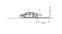
図5は、車両1と障害物Bとの間に対象物Tが存在する場合の一例の説明図である。例えば、障害物Bが検出された状態で運転者がアクセルペダル22Aを踏むと、車両1の駆動力は、衝突回避制御によって制限された状態であっても、制限要求駆動力に応じて車両1が加速されるはずである。しかし、例えば、図5に示すような対象物Tである段差に車輪が接しているときには、車両1は、停止した状態、または、所定の車速に達しない状態となる場合がある。このような場合、対象物判定部30Dは、車両1と障害物Bとの間に対象物Tが存在すると判定してもよい。
Figure 5 is an explanatory diagram of an example of a case where an object T exists between the
ここで、運転者が、もう少し障害物Bに接近させて車両1を停車させることを所望する場合がある。このような場合、車両1の進行方向Xへの駆動力を制限する衝突回避制御が行われると、段差などの対象物Tの影響などにより、車両1の走行に必要な駆動力を得ることが出来ない場合がある。
At this point, the driver may wish to stop
そこで、衝突回避制御部30Cでは、車両1が対象物Tを乗り越えるときに、車両1の車速が設定車速に到達するまで、要求駆動力f10より小さい駆動力である初期駆動力から駆動力を徐々に引き上げる。そして、衝突回避制御部30Cは、車両1の車速が設定車速に到達すると、駆動力を引き下げる、衝突回避制御を実行する。
Therefore, when the
設定車速には、例えば、車両1が対象物Tを乗り越えるために最低限必要な車速を予め定めればよい。なお、設定車速は、ユーザによるメータコンピュータ24などを介した操作指示などに応じて、適宜変更可能としてもよい。
The set vehicle speed may be, for example, a minimum vehicle speed required for the
図6A~図6Cは、車両1と障害物Bとの間に対象物Tが存在する場合の、衝突回避制御の一例の説明図である。
Figures 6A to 6C are explanatory diagrams of an example of collision avoidance control when an object T is present between the
図6Aは、対象物Tを乗り越えるときの、時間と障害物Bまでの距離との関係の説明図である。図6A中、横軸は時間を表し、縦軸は車両1から障害物Bまでの距離を表す。図6Bは、対象物Tを乗り越えるときの車両1の駆動力の一例の説明図である。図6B中、横軸は時間を表し、縦軸は駆動力を表す。図6Cは、時間と車速との関係の説明図である。図6C中、横軸は時間を表し、縦軸は車両1の車速を表す。
Figure 6A is an explanatory diagram of the relationship between time and the distance to obstacle B when going over object T. In Figure 6A, the horizontal axis represents time, and the vertical axis represents the distance from
障害物Bが検出されると、衝突回避制御部30Cは、運転者が操作したアクセルペダル22Aのアクセル開度から定まる要求駆動力f10より小さい駆動力となるように車両1の駆動力を制御し、障害物Bまでの距離が短くなるほどより小さい駆動力となるように、走行制御部20を制御する。
When an obstacle B is detected, the collision avoidance control unit 30C controls the driving force of the
このとき、車両1と障害物Bとの間に対象物Tが存在する場合を想定する。例えば、タイミングt1の時点で、車両1の進行方向の下流側の車輪が対象物Tに到達したと想定する。このタイミングt1時点で運転者がアクセルペダル22Aを踏んでも、車両1の駆動力は、初期駆動力fiに制限されている。
At this time, it is assumed that an object T exists between the
初期駆動力fiは、例えば、車両1と障害物Bとの間に対象物Tが存在しない場合の駆動力の制御時の、障害物Bまでの距離に対応する駆動力である。具体的には、初期駆動力fiは、図4Bの線図40によって表される駆動力の制御が行われた時の、障害物Bまでの距離に対応する駆動力である。なお、初期駆動力fiには、運転者が操作したアクセルペダル22Aのアクセル開度から定まる要求駆動力f10より小さい駆動力であればよく、線図40によって表される駆動力に限定されない。
The initial driving force fi is, for example, a driving force corresponding to the distance to the obstacle B when the driving force is controlled in a case where there is no object T between the
図6A~図6Cに戻り説明を続ける。車両1の駆動力が初期駆動力fiに制限されているため、車両1は段差などの対象物Tを乗り越えることができない。そこで、図6Bの線図42および図6Cの線図43に示すように、衝突回避制御部30Cは、車両1が対象物Tを乗り越えるときに、車両1の車速が設定車速に到達するまで、初期駆動力fiから駆動力を徐々に引き上げる。ここで「駆動力を徐々に引き上げる」とは、車速の検出結果を基に駆動力を経時的に引き上げていくという意味であり、駆動力の引き上げ速度の絶対値を規定するものではない。
Returning to Figures 6A to 6C, the explanation will continue. Because the driving force of
具体的には、図6Bのタイミングt1からタイミングt2に示すように、衝突回避制御部30Cは、駆動力の制限を徐々に解除する。駆動力を徐々に引き上げられた車両1は、対象物Tを登り始め、車速が出始める。また、車両1から障害物Bまでの距離は、距離LT1から距離LT2へと減少していく。
Specifically, as shown from timing t1 to timing t2 in FIG. 6B, the collision avoidance control unit 30C gradually releases the limit on the driving force. With the driving force gradually increased, the
衝突回避制御部30Cは、車両1の車速が設定車速に到達すると、対象物Tを乗り越えたと判断し、駆動力を引き下げる。図6A~図6Cに示す例では、衝突回避制御部30Cは、タイミングt2の時点で、車両1が対象物Tを乗り越えたと判断する。そして、衝突回避制御部30Cは、タイミングt2の時点の車両1から障害物Bまでの距離LT2に応じた駆動力f0まで、駆動力を引き下げる。
When the vehicle speed of the
車両1は、タイミングt2からタイミングt3の期間、衝突回避制御部30Cによって制御された駆動力となるまで加速する。しかし、障害物Bまでの距離が減少していくため、車両1の駆動力および加速度は低下していく。タイミングt3の時点では、駆動力がゼロとなり、車両1の加速が禁止される。このため、車両1は等速で障害物Bへ接近する。そして、タイミングt4の時点で、ブレーキ制御が発動し、障害物Bとの距離が予め定めた距離となるまでに車両1は停止する。
During the period from timing t2 to timing t3,
このため、衝突回避制御の駆動力の推移を示す線図42は、対象物Tの乗り越えに相当する位置にピークPを有するものとなる。このピークPの引き上げ領域PAの部分が、初期駆動力fiから駆動力を徐々に引き上げる引き上げ部分に相当する。また、このピークPの引き下げ領域PBの部分が、車両1の車速が設定車速に到達した後に障害物Bまでの距離に応じて駆動力を引き下げる引き下げ部分に相当する。なお、衝突回避制御部30Cは、ピークPの最大値の駆動力が、要求駆動力f10未満の最大駆動力fmax以下となるように駆動力を調整する。
Therefore, the
なお、図6A~図6Cは、対象物Tに到達したときに車両1が停止状態であった場合を想定して示す。そして、対象物Tの乗り越えのためにアクセルペダル22Aが操作された場面を一例として説明している。この場合、設定車速は、例えば、車両1が動き出し且つ対象物Tを乗り越え可能な車速に予め設定されていればよい。また、設定車速は、車両1の状態などに応じて適宜再設定可能としてもよい。
Note that Figures 6A to 6C show the assumption that the
衝突回避制御部30Cは、受付部30Aで受付ける車輪速度の情報をモニタすることで、車速の変化を検出し、駆動力の制御に用いればよい。詳細には、衝突回避制御部30Cは、受付部30AでブレーキECU20Bから受付けた車輪速度の情報から、車両1の車速を算出すればよい。
The collision avoidance control unit 30C may detect changes in vehicle speed by monitoring the wheel speed information received by the reception unit 30A, and use the changes in vehicle speed to control the driving force. In detail, the collision avoidance control unit 30C may calculate the vehicle speed of the
なお、図6Bには、駆動力を徐々に引き上げる例示として、駆動力を連続的に引き上げる例を示した。しかし、駆動力の引き上げは、階段状の引き上げであってもよく、連続的なの引き上げに限定されない。 Note that FIG. 6B shows an example of gradually increasing the driving force, in which the driving force is increased continuously. However, the increase in the driving force may be a step-like increase, and is not limited to a continuous increase.
衝突回避制御部30Cによる駆動力の制御によって、車両1は、対象物Tを乗り越え且つ障害物Bへの衝突を回避することができる。
By controlling the driving force using the collision avoidance control unit 30C, the
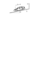
図7A~図7Cは、対象物T乗り越えの一例の説明図である。衝突回避制御部30Cによる駆動力の制御によって、車両1は、図7Aに示す対象物Tに到達した状態から、図7Bおよび図7Cに示すように、対象物Tを乗り越えて障害物Bの手前で停止することが可能となる。
Figures 7A to 7C are explanatory diagrams of an example of getting over an object T. By controlling the driving force by the collision avoidance control unit 30C, the
ここで、対象物Tを乗り越えた後の車両1と障害物Bとの距離によっては、衝突回避制御部30Cによる駆動力の制限が厳しすぎて、障害物Bに十分に寄って停止することが困難となる場合がある。また、駆動力の制限が緩すぎて、車両1が障害物Bに接触してしまう場合がある。
Here, depending on the distance between the
図2に戻り説明を続ける。そこで、本実施形態では、算出部30Eは、衝突回避制御が開始された車両1と障害物Bとの間に存在する対象物Tを乗り越えたときの、車両1と障害物Bとの距離に応じて、車両1が対象物Tを乗り越えたときの駆動力の引き下げ量を算出する。
Returning to FIG. 2 for further explanation, in this embodiment, the
車両1が対象物Tを乗り越えたとき、とは、車両1が対象物Tを乗り越えた時点を意味する。詳細には、車両1が対象物Tを乗り越えたとき、とは、車両1の車輪が対象物Tに乗り上げた後に該車輪が対象物T上から外れたとき、を意味する。
When the
具体的には、車両1が進行し、対象物Tである段差を乗り越える場合を想定する。この場合、対象物Tを乗り越えたとき、とは、車両1が進行することで車両1の進行方向の下流側の車輪が対象物Tである段差に乗り上げた後に、該車輪が対象物Tである段差上から外れた状態となったとき、を意味する。車輪が対象物Tである段差上から外れた状態とは、対象物Tの形状によって異なる。例えば、対象物Tが段差である場合には、車輪が対象物Tから外れた状態となったときとは、段差を形成する頂点部分を車輪が超えた状態を意味する。また、対象物Tがフラップである場合には、車輪が対象物Tから外れた状態となったときとは、車輪が対象物Tに乗り上げた後に対象物Tから降りたときを意味する。
Specifically, assume that the
算出部30Eは、車両1が対象物Tを乗り越えたか否か判断する。車両1が対象物Tを乗り越えたか否かの判断は、例えば、以下の方法で実行すればよい。
The
例えば、算出部30Eは、衝突回避制御部30Cによって衝突回避制御されている車両1の車速が、初期駆動力fiから駆動力を徐々に引き上げられて設定車速に到達したときに、車両1が対象物Tを乗り越えたと判断すればよい。
For example, the
なお、算出部30Eは、他の方法で、車両1が対象物Tを乗り越えたと判断してもよい。例えば、算出部30Eは、センサECU14から受付けた検知結果情報に対象物Tを表す対象物情報が含まれる状態から、含まれない状態へと切り替わったときに、車両1が対象物Tを乗り越えたと判断する。また、例えば、算出部30Eは、Gセンサ16で計測された車両1の上下方向および前後方向の加速度が、対象物Tを乗り越えたときの所定の加速度のパターンを示す場合に、対象物Tを乗り越えたと判断してもよい。対象物Tを乗り越えたときの加速度のパターンは、例えば、対象物Tの形状などの特長を表す情報に対応付けて、予め記憶部26へ記憶しておけばよい。そして、算出部30Eは、センサECU14によって検出された対象物Tの形状などの特長を表す情報に対応するパターンを記憶部26から検索する。そして、算出部30Eは、対象物Tを乗り越えたときの加速度のパターンに一致する、該対象物Tの形状に対応するパターンが記憶部26に存在する場合に、対象物Tを乗り越えたと判断すればよい。
The
本実施形態では、算出部30Eは、衝突回避制御されている車両1の車速が初期駆動力fiから駆動力を徐々に引き上げられて設定車速に到達したときに、車両1が対象物Tを乗り越えたと判断する形態を一例として説明する。
In this embodiment, the
そして、算出部30Eは、車両1が対象物Tを乗り越えたときの車両1と障害物Bとの距離に応じて、車両1が対象物Tを乗り越えたときの駆動力の引き下げ量を算出する。
Then, the
対象物Tを乗り越えたときの駆動力の引き下げ量とは、図6で説明した線図42に含まれるピークPの引き下げ領域PBにおける駆動力の引き下げ量を意味する。すなわち、引き下げ量は、対象物Tの乗り越え時に車両1の車速が設定車速に到達したときに引き下げる、駆動力の引き下げ量である。
The reduction amount of the driving force when going over the object T means the reduction amount of the driving force in the reduction area PB of the peak P included in the
算出部30Eは、車両1が対象物Tを乗り越えたときの、車両1と障害物Bとの距離が短いほど、大きい引き下げ量を算出する。また、算出部30Eは、車両1が対象物Tを乗り越えたときの、車両1と障害物Bとの距離が長いほど、小さい引き下げ量を算出する。
The
算出部30Eは、車両1が対象物Tを乗り越えた時点で検出された検出結果情報に含まれる、車両1と対象物Tとの距離を用いて、引き下げ量を算出すればよい。
The
なお、算出部30Eは、車両1が対象物Tを乗り越える前のタイミングで、引き下げ量を推定してもよい。
The
この場合、算出部30Eは、対象物Tまでの距離情報、障害物Bまでの距離情報、車両1の車輪速度の情報、車両1の車輪速度から算出される加速度、車両1の走行する路面の傾斜、などの情報を受付部30Aから受付ける。そして、算出部30Eは、これらの情報を用いて、車両1が対象物Tを乗り越えたときの車両1と障害物Bとの距離を公知の方法で推定してもよい。
In this case, the
駆動力制御部30Fは、車両1が対象物Tを乗り越えるときに、車両1の車速が設定車速に到達するまで、運転者が操作したアクセルペダル22Aのアクセル開度から定まる要求駆動力f10より小さい駆動力である初期駆動力fiから駆動力を徐々に引き上げる。そして、駆動力制御部30Fは、車両1の車速が設定車速に到達すると、駆動力を、算出部30Eで算出された引き下げ量引き下げるように、衝突回避制御部30Cを制御する。
When the
図8Aおよび図8Bは、対象物Tを乗り越えたときの車両1と障害物Bとの距離Lが、距離Lbである場合の一例の説明図である。図8B中、横軸は、車両1から障害物Bまでの距離を示す。図8B中、Bの地点が、障害物Bの位置、すなわち、障害物Bまでの距離が0の地点である。また、図8B中、LT1は、車両1が対象物Tに到達した時点の車両1と障害物Bとの距離である。また、図8B中、LT2は、車両1が対象物Tを乗り越えたときの車両1と障害物との距離Lbである。図8B中、縦軸は、車両1の駆動力を示す。
Figures 8A and 8B are explanatory diagrams of an example in which the distance L between
図6Bを用いて説明した線図42と同様に、障害物Bが検出された場合の衝突回避制御部30Cによる駆動力の制御によって、衝突回避制御の駆動力の推移を示す線図46は、対象物Tの乗り越えに相当する位置にピークPを有するものとなる。
Similar to line 42 described using FIG. 6B,
そして、本実施形態では、衝突回避制御部30Cは、車両1の車速が設定車速に到達すると、駆動力制御部30Fの制御によって、算出部30Eで算出された距離Lbに応じた引き下げ量C、駆動力を引き下げる。引き下げ量Cは、距離Lが短いほど大きい量である。
In this embodiment, when the speed of the
このため、車両1が対象物Tを乗り越えたときの距離Lが短いほど、ピークPにおける引き下げ領域PBの駆動力の引き下げ量C、すなわち、ピークPの頂点からの駆動力の引き下げ量Cが大きくなる。図8Bには、ピークPの頂点の時点の駆動力f7から、駆動力f2まで、駆動力を引き下げ量C、引き下げた例を示す。
Therefore, the shorter the distance L when the
このため、車両1が対象物Tを乗り越えたときの障害物Bとの距離Lが短いほど、駆動力は強くまたは厳しく抑制されることとなる。よって、対象物Tを乗り越えた後の車両1が、障害物Bに接触することが抑制される。
Therefore, the shorter the distance L between the
また、車両1が対象物Tを乗り越えたときの距離Lが長いほど、ピークPにおける引き下げ領域PBの駆動力の引き下げ量C、すなわち、ピークPの頂点からの駆動力の引き下げ量Cが小さくなる。
In addition, the longer the distance L when the
このため、車両1が対象物Tを乗り越えたときの障害物Bとの距離Lが長いほど、駆動力は弱くまたは緩く抑制されることとなる。よって、対象物Tを乗り越えた後の車両1が、障害物Bから大きく離れた位置で停止することが抑制される。すなわち、車両1が対象物Tを乗り越えたときの障害物Bとの距離Lが長い場合であっても、車両1が障害物Bに十分に寄って停止することが可能となる。また、障害物Bから大きく離れた位置で車両1が停止することによって、運転者に違和感を与えることを抑制することができる。
Therefore, the longer the distance L between the
なお、車両1が障害物Bに至る路面に勾配がある場合がある。
Note that the road surface on which
図9は、車両1が障害物Bに至る路面Rに勾配がある場合の説明図である。路面に勾配がある場合、衝突回避制御部30Cによる駆動力の制限が厳しすぎて、障害物Bに十分に寄って停止することが困難となる場合がある。また、駆動力の制限が緩すぎて、障害物Bに接触してしまう場合がある。
Figure 9 is an explanatory diagram of a case where the road surface R on which the
そこで、算出部30Eは、対象物Tを乗り越えたときの車両1と障害物Bとの距離Lと、車両1が障害物Bに至る路面Rの勾配率と、に応じて、引き下げ量Cを算出してもよい。路面Rの勾配率とは、水平方向に対する車両1の車体の傾きを意味する。図9では、勾配率を、S%として示した。
The
図2に戻り説明を続ける。上述したように、Gセンサ16から受付ける加速度の計測結果情報は、車両1の車輪速度から算出される加速度と、車両1の走行する路面Rの傾斜である車両1の傾きによる重力加速度と、の合計値である。このため、算出部30Eは、Gセンサ16で計測された車両1の前後方向の加速度の計測結果情報から、車輪速度によって算出される加速度を減算することで、車両1の傾きである路面Rの傾斜を算出できる。そして、算出部30Eは、算出した路面Rの傾斜を、勾配率として算出すればよい。
Returning to FIG. 2 for further explanation, as described above, the measurement result information of acceleration received from the
そして、算出部30Eは、距離Lが短いほど大きく、且つ、勾配率が大きいほど小さい、引き下げ量Cを算出する。詳細には、例えば、算出部30Eは、距離Lが短いほど大きい引き下げ量Cを算出する。そして、算出部30Eは、算出した引き下げ量Cを、勾配率が大きいほど小さい値となるように補正することで、駆動力の制御に用いる引き下げ量Cを算出すればよい。
Then, the
そして、衝突回避制御部30Cは、対象物Tの乗り越え時に車両1の車速が設定車速に到達すると、駆動力制御部30Fの制御によって、算出部30Eで算出された距離Laおよび勾配率に応じた引き下げ量C、駆動力を引き下げる。
Then, when the vehicle speed of the
このため、車両1の駆動力は、車両1が対象物Tを乗り越えたときの障害物Bとの距離が長いほど弱くまたは緩く、且つ、路面Rの勾配率が大きいほど弱くまたは緩く抑制されることとなる。よって、対象物Tを乗り越えた後の車両1が、障害物Bから大きく離れた位置で停止することが抑制される。すなわち、障害物Bに十分に寄って車両1を停止させることが可能となる。また、障害物Bから大きく離れた位置で車両1が停止することによって、運転者に違和感を与えることを抑制することができる。
Therefore, the driving force of the
なお、図6A~図6Cには、対象物Tに到達したときに車両1が停止状態であった場合を想定して説明した。しかし、車両1が対象物Tへの到達時の車速はゼロとは限られない。例えば、車両1が移動を継続しながら対象物Tを乗り越える場合がある。すなわち、車両1の対象物Tへの到達時の車速が高速である場合や、低速である場合など、様々な場合がある。
Note that in the explanation of Figures 6A to 6C, it is assumed that the
そこで、算出部30Eは、車両1の対象物Tへの到達時の車速に応じて、初期駆動力fiからの駆動力の引き上げ率を算出する。初期駆動力fiからの駆動力の引き上げ率とは、上述したピークPの引き上げ領域PAにおける、駆動力の引き上げ率を意味する。駆動力の引き上げ率は、単位時間あたりの駆動力の引き上げ率、単位距離あたりの駆動力の引き上げ率、の何れであってもよい。
Therefore, the
算出部30Eは、車両1の対象物Tへの到達時の車速を導出する。
The
例えば、算出部30Eは、車両1が対象物Tへ到達したときの車両1の車速を、ブレーキECU20Bから受付けた車輪速度の情報から算出する。車両1が対象物Tへ到達したタイミングの判断は、例えば、受付部30Aで受付けた計測結果情報に、物体が対象物Tであることを示す対象物情報が含まれ、且つ、対象物Tとの距離がゼロである情報が含まれる場合に、車両1が対象物Tへ到達したと判断すればよい。また、算出部30Eは、他の方法で、車両1が対象物Tへ到達したと判断してもよい。例えば、算出部30Eは、衝突回避制御されている車両1の車速が、走行制御部20へ出力されている制限要求駆動力に対応する車速から該車速未満へと切り替わったときに、対象物Tへ到達したと判断してもよい。
For example, the
なお、算出部30Eは、車両1が対象物Tへ到達する前に、車両1が対象物Tへ到達したときの車両1の車速を推定してもよい。この場合、算出部30Eは、対象物Tまでの距離情報、障害物Bまでの距離情報、車両1の車輪速度の情報、車両1の車輪速度から算出される加速度、車両1の走行する路面Rの傾斜、などの情報を受付部30Aから受付ける。そして、算出部30Eは、これらの情報を用いて、車両1が対象物Tに到達したときの車両1の車速を、公知の方法で推定すればよい。
The
そして、算出部30Eは、車両1が対象物Tへ到達したときの車両1の車速に応じて、ピークPにおける、初期駆動力fiからの引き上げ率を算出する。
Then, the
算出部30Eは、車両1の対象物Tへの到達時の車速が速いほど、低い引き上げ率を算出する。すなわち、算出部30Eは、車両1の対象物Tへの到達時の車速が速いほど、上記ピークPの引き上げ領域PAにおける駆動力の引き上げ率として、低い引き上げ率を算出する。
The
そして、駆動力制御部30Fは、対象物Tを車両1が乗り越えるときに、設定車速に到達するまで、算出された引き上げ率で初期駆動力fiから駆動力を徐々に引き上げるように、衝突回避制御部30Cを制御する。
Then, when the
図10Aは、対象物Tに到達したときの車両1の車速が速い場合の、衝突回避制御の一例の説明図である。図10A中、横軸は、車両1から障害物Bまでの距離を示す。図10A中、Bの地点が、障害物Bの位置、すなわち、障害物Bまでの距離が0の地点である。また、図10A中、LT1は、車両1が対象物Tに到達した時点の車両1と障害物Bとの距離Lである。また、図10A中、LT2は、車両1が対象物Tを乗り越えたときの車両1と障害物との距離Lである。図10A中、縦軸は、車両1の駆動力を示す。
Figure 10A is an explanatory diagram of an example of collision avoidance control when the vehicle speed of
図6Bを用いて説明した線図42と同様に、障害物Bが検出された場合の衝突回避制御部30Cによる駆動力の制御によって、衝突回避制御の駆動力の推移を示す線図46は、対象物Tの乗り越えに相当する位置にピークPを有するものとなる。
Similar to line 42 described using FIG. 6B,
車両1が対象物Tに到達すると、衝突回避制御部30Cは、駆動力制御部30Fの制御によって、算出部30Eで算出された引き上げ率αaで、駆動力を引き上げる。そして、衝突回避制御部30Cは、車両1の車速が設定車速に到達すると、駆動力制御部30Fの制御によって、算出部30Eで算出された距離Lに応じた引き下げ量C、駆動力を引き下げる。
When the
このため、車両1が対象物Tに到達したときの車速が速いほど、駆動力は緩くまたは弱く引き上げられることとなる。このため、車両1が対象物Tに到達したときの車速が速い場合、車両1は自車両の慣性を活用して対象物Tを乗り越えることが可能となる。また、対象物Tを乗り越えた後の駆動力の抑制との差分を減らし、急減速を抑制することができる。このため、運転者の違和感の低減を図ることができる。
Therefore, the faster the vehicle speed when the
図10Bは、対象物Tに到達したときの車両1の車速が図10Aに示す例より遅い場合の、衝突回避制御の一例の説明図である。図10B中、横軸は、車両1から障害物Bまでの距離を示す。図10B中、Bの地点が、障害物Bの位置、すなわち、障害物Bまでの距離が0の地点である。また、図10B中、LT1は、車両1が対象物Tに到達した時点の車両1と障害物Bとの距離Lである。また、図10B中、LT2は、車両1が対象物Tを乗り越えたときの車両1と障害物との距離Lである。図10B中、縦軸は、車両1の駆動力を示す。
Figure 10B is an explanatory diagram of an example of collision avoidance control in a case where the vehicle speed of
図6Bを用いて説明した線図42と同様に、障害物Bが検出された場合の衝突回避制御部30Cによる駆動力の制御によって、衝突回避制御の駆動力の推移を示す線図48は、対象物Tの乗り越えに相当する位置にピークPを有するものとなる。 Similar to line 42 described using FIG. 6B, line 48 showing the progression of the driving force of the collision avoidance control, which is caused by the control of the driving force by the collision avoidance control unit 30C when an obstacle B is detected, has a peak P at a position corresponding to passing over the object T.
車両1が対象物Tに到達すると、衝突回避制御部30Cは、駆動力制御部30Fの制御によって、算出部30Eで算出された引き上げ率αbで、駆動力を引き上げる。この例では、図10Aに示す例よりも遅い車速で車両1が対象物Tに到達した場合を想定する。この場合、算出部30Eで算出される引き上げ率αbは、図10Aを用いて説明した引き上げ率αaより大きい。そして、衝突回避制御部30Cは、車両1の車速が設定車速に到達すると、駆動力制御部30Fの制御によって、算出部30Eで算出された距離Lに応じた引き下げ量C、駆動力を引き下げる。
When the
このため、車両1が対象物Tに到達したときの車速が遅いほど、駆動力は強くまたは大きく引き上げられることとなる。このため、車両1が対象物Tに到達したときの車速が遅い場合であっても、車両1は自車両の慣性を活用して対象物Tを乗り越えることが可能となる。また、対象物Tを乗り越えた後の駆動力の抑制との差分を減らし、急減速を抑制することができる。このため、運転者の違和感の低減を図ることができる。
Therefore, the slower the vehicle speed when the
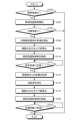
次に、本実施形態の運転支援装置10で実行する情報処理の一例を説明する。
Next, an example of information processing performed by the driving
図11は、運転支援装置10で実行される情報処理の一例を示すフローチャートである。なお、受付部30Aは、センサECU14、Gセンサ16、舵角センサ18、エンジンECU20Aから、およびブレーキECU20Bの各々から、上述した各種の情報を順次受付けているものとする。
Figure 11 is a flowchart showing an example of information processing executed by the driving
検出部30Bは、車両1の進行方向に障害物Bが検出されたか否かを判断する(ステップS100)。ステップS100で否定判断すると(ステップS100:No)、本ルーチンを終了する。ステップS100で肯定判断すると(ステップS100:Yes)、ステップS102へ進む。 The detection unit 30B determines whether or not an obstacle B has been detected in the traveling direction of the vehicle 1 (step S100). If the determination in step S100 is negative (step S100: No), the routine ends. If the determination in step S100 is positive (step S100: Yes), the routine proceeds to step S102.
ステップS102では、衝突回避制御部30Cが、車両1の駆動力を制御して障害物Bへの衝突を回避する衝突回避制御を開始する(ステップS102)。
In step S102, the collision avoidance control unit 30C starts collision avoidance control to control the driving force of the
次に、対象物判定部30Dが、車両1と障害物Bとの間に対象物Tが存在するか否かを判断する(ステップS104)。対象物Tが存在しないと判断した場合(ステップS104)、本ルーチンを終了する。すなわち、対象物Tが存在しない場合には、図4Bの線図40によって表される駆動力の制御が行われる。
Next, the
対象物Tが存在すると判断した場合(ステップS104:Yes)、ステップS106へ進む。ステップS106では、算出部30Eが、車両1の対象物Tへの到達時の車速を導出する(ステップS106)。
If it is determined that the object T is present (step S104: Yes), the process proceeds to step S106. In step S106, the
そして、算出部30Eは、ステップS106で導出した車速に応じて、初期駆動力fiからの駆動力の引き上げ率を算出する(ステップS108)。算出部30Eは、ステップS106で導出された車速が速いほど、低い引き上げ率を算出する。
Then, the
駆動力制御部30Fは、車両1が対象物Tを乗り越えるときに、ステップS108で算出された引き上げ率で初期駆動力fiから駆動力を徐々に引き上げるように、衝突回避制御部30Cを制御する(ステップS110)。
When the
駆動力制御部30Fは、車両1の車速が設定車速に到達したか否かを判断する(ステップS112)。駆動力制御部30Fは、車両1の車速が設定車速に到達したと判断するまで否定判断(ステップS112:No)を繰り返す。そして、駆動力制御部30Fは、車両1の車速が設定車速に到達したと判断すると(ステップS112:Yes)、ステップS114へ進む。
The driving force control unit 30F determines whether the vehicle speed of the
ステップS114では、算出部30Eは、車両1と障害物Bとの距離Lを取得する(ステップS114)。上述したように、本実施形態では、算出部30Eは、駆動力が初期駆動力fiから徐々に引き上げられて車両1の車速が設定車速に到達したときに、車両1が対象物Tを乗り越えたと判断する。このため、ステップS114で肯定判断されたときに、車両1と障害物Bとの距離を取得することで、算出部30Eは、衝突回避制御が開始された車両1と障害物Bとの間に存在する対象物Tを車両1が乗り越えたときの、車両1と障害物Bとの距離Lを取得する。
In step S114, the
次に、算出部30Eは、車両1が障害物Bへ至る路面Rの勾配率を特定する(ステップS116)。算出部30Eは、例えば、Gセンサ16で計測された車両1の前後方向の加速度の計測結果情報から、車輪速度によって算出される加速度を減算することで、車両1の傾きである路面Rの傾斜を算出する。そして、算出部30Eは、算出した路面Rの傾斜を、勾配率として特定する。
Next, the
次に、算出部30Eは、ステップS114で取得した距離Lが短いほど大きく、且つ、ステップS116で特定した勾配率が大きいほど小さい、引き下げ量Cを算出する(ステップS118)。
Next, the
駆動力制御部30Fは、対象物Tの乗り越え時に車両1の車速が設定車速に到達すると、ステップS118で算出された引き下げ量C、駆動力を引き下げるように衝突回避制御部30Cを制御する(ステップS120)。
When the vehicle speed of the
次に、衝突回避制御部30Cは、車両1と障害物Bとの距離が目標距離に到達したか否かを判断する(ステップS122)。目標距離は、予め定めればよい。また、ユーザによるメータコンピュータ24などの操作指示によって、適宜変更可能としてもよい。衝突回避制御部30Cは、肯定判断(ステップS122:Yes)するまで否定判断(ステップS122:No)を繰り返す。ステップS122で肯定判断すると(ステップS122:Yes)、本ルーチンを終了する。
Next, the collision avoidance control unit 30C determines whether the distance between the
以上説明したように、本実施形態の運転支援装置10は、検出部30Bと、衝突回避制御部30Cと、算出部30Eと、駆動力制御部30Fと、を備える。検出部30Bは、車両1の進行方向の障害物Bを検出する。衝突回避制御部30Cは、障害物Bが検出された場合に、車両1の駆動力を制御して障害物Bへの衝突回避制御を行う。算出部30Eは、衝突回避制御が開始された車両1と障害物Bとの間に存在する対象物Tを乗り越えたときの車両1と障害物Bとの距離に応じて、車両1が対象物Tを乗り越えたときの駆動力の引き下げ量Cを算出する。駆動力制御部30Fは、車両1が対象物Tを乗り越えるときに、車両1の車速が設定車速に到達するまで、運転者が操作したアクセルペダル22Aのアクセル開度から定まる要求駆動力f10より小さい駆動力である初期駆動力fiから駆動力を徐々に引き上げ、車両1の車速が設定車速に到達すると、駆動力を引き下げ量C引き下げるように衝突回避制御部30Cを制御する。
As described above, the driving
このように、本実施形態の運転支援装置10は、車両1と障害物Bとの間に存在する対象物Tを乗り越えたときの車両1と障害物Bとの距離に応じて、車両1が対象物Tを乗り越えたときの駆動力の引き下げ量Cを算出する。そして、運転支援装置10では、車両1が対象物Tを乗り越えるときに、車両1の車速が設定車速に到達すると、駆動力を引き下げ量C引き下げるように衝突回避制御部30Cを制御する。
In this way, the driving
このため、対象物Tを乗り越えたときの車両1と障害物Bとの距離に応じて、車両1が対象物Tを乗り越えたときの駆動力の弱め方または緩め方が調整されることとなる。よって、対象物Tを乗り越えた後の車両1が、障害物Bから大きく離れた位置で停止することが抑制される。すなわち、車両1が対象物Tを乗り越えたときの障害物Bとの距離が長い場合であっても、障害物Bに十分に寄って停止することが可能となる。また、障害物Bから大きく離れた位置で車両1が停止することによって、運転者に違和感を与えることを抑制することができる。また、対象物Tを乗り越えた後の車両1が、障害物Bに接触することが抑制される。
Therefore, the weakening or loosening of the driving force when the
従って、本実施形態の運転支援装置10は、良好な車両走行支援を行うことができる。
Therefore, the driving
なお、本実施形態では、運転支援装置10は、車両1に搭載された形態を一例として説明した。しかし、運転支援装置10は、車両1の外部に搭載された構成であってもよい。運転支援装置10は、車両1に設けられたセンサECU14、Gセンサ16、舵角センサ18、走行制御部20、メータコンピュータ24、および、記憶部26、などの各種の電子機器と通信可能に接続されていればよい。このため、運転支援装置10は、車両1の外部に設けられた情報処理装置に搭載された形態であってもよい。この場合、運転支援装置10の搭載された情報処理装置と、上記各種の電子機器とを、ネットワークなどを介して通信可能に構成すればよい。
In the present embodiment, the driving
なお、上記には、実施形態を説明したが、上記実施形態は、例として提示したものであり、発明の範囲を限定することは意図していない。上記新規な実施形態は、その他の様々な形態で実施されることが可能であり、発明の要旨を逸脱しない範囲で、種々の省略、置き換え、変更を行うことができる。上記実施形態は、発明の範囲または要旨に含まれるとともに、特許請求の範囲に記載された発明とその均等の範囲に含まれる。 Although the above describes an embodiment, the above embodiment is presented as an example and is not intended to limit the scope of the invention. The above novel embodiment can be implemented in various other forms, and various omissions, substitutions, and modifications can be made without departing from the gist of the invention. The above embodiment is within the scope or gist of the invention, and is included in the scope of the invention and its equivalents described in the claims.
1 車両
10 運転支援装置
30B 検出部
30C 衝突回避制御部
30D 対象物判定部
30E 算出部
30F 駆動力制御部
1
Claims (10)
前記障害物が検出された場合に、前記車両の駆動力を制御して前記障害物への衝突回避制御を行う衝突回避制御部と、
前記衝突回避制御が開始された前記車両と前記障害物との間に存在する対象物を乗り越えたときの前記車両と前記障害物との距離に応じて、前記車両が前記対象物を乗り越えたときの駆動力の引き下げ量を算出する算出部と、
前記車両が前記対象物を乗り越えるときに、前記車両の車速が設定車速に到達するまで、運転者が操作したアクセルペダルのアクセル開度から定まる要求駆動力より小さい駆動力である初期駆動力から駆動力を徐々に引き上げ、前記車両の車速が設定車速に到達した後、駆動力を前記引き下げ量引き下げるように前記衝突回避制御部を制御する駆動力制御部と、
を備え、
前記算出部は、
前記距離が短いほど大きい前記引き下げ量を算出する、
運転支援装置。 A detection unit that detects an obstacle in the traveling direction of the vehicle;
a collision avoidance control unit that controls a driving force of the vehicle to avoid a collision with the obstacle when the obstacle is detected;
a calculation unit that calculates a reduction amount of a driving force when the vehicle goes over an object that exists between the vehicle and the obstacle when the collision avoidance control is started, in accordance with a distance between the vehicle and the obstacle when the vehicle goes over the object;
a driving force control unit that controls the collision avoidance control unit so that, when the vehicle goes over the object, a driving force is gradually increased from an initial driving force that is smaller than a required driving force determined from an accelerator opening degree of an accelerator pedal operated by a driver until the vehicle speed of the vehicle reaches a set vehicle speed, and the driving force is decreased by the reduction amount after the vehicle speed of the vehicle reaches the set vehicle speed;
Equipped with
The calculation unit is
The shorter the distance, the larger the amount of reduction is calculated.
Driving assistance device.
前記障害物が検出された場合に、前記車両の駆動力を制御して前記障害物への衝突回避制御を行う衝突回避制御部と、
前記衝突回避制御が開始された前記車両と前記障害物との間に存在する対象物を乗り越えたときの前記車両と前記障害物との距離に応じて、前記車両が前記対象物を乗り越えたときの駆動力の引き下げ量を算出する算出部と、
前記車両が前記対象物を乗り越えるときに、前記車両の車速が設定車速に到達するまで、運転者が操作したアクセルペダルのアクセル開度から定まる要求駆動力より小さい駆動力である初期駆動力から駆動力を徐々に引き上げ、前記車両の車速が設定車速に到達した後、駆動力を前記引き下げ量引き下げるように前記衝突回避制御部を制御する駆動力制御部と、
を備え、
前記算出部は、
前記車両の前記対象物への到達時の車速に応じて、前記初期駆動力からの駆動力の引き上げ率を算出し、
前記駆動力制御部は、
前記対象物を前記車両が乗り越える時に、前記設定車速に到達するまで、前記初期駆動力から駆動力を前記引き上げ率で徐々に引き上げるように、前記衝突回避制御部を制御する、
運転支援装置。 A detection unit that detects an obstacle in the traveling direction of the vehicle;
a collision avoidance control unit that controls a driving force of the vehicle to avoid a collision with the obstacle when the obstacle is detected;
a calculation unit that calculates a reduction amount of a driving force when the vehicle goes over an object that exists between the vehicle and the obstacle when the collision avoidance control is started, in accordance with a distance between the vehicle and the obstacle when the vehicle goes over the object;
a driving force control unit that controls the collision avoidance control unit so that, when the vehicle goes over the object, a driving force is gradually increased from an initial driving force that is smaller than a required driving force determined from an accelerator opening degree of an accelerator pedal operated by a driver until the vehicle speed of the vehicle reaches a set vehicle speed, and the driving force is decreased by the reduction amount after the vehicle speed of the vehicle reaches the set vehicle speed;
Equipped with
The calculation unit is
calculating a rate of increase in driving force from the initial driving force in accordance with a vehicle speed at the time when the vehicle reaches the object;
The driving force control unit is
When the vehicle passes over the object, the collision avoidance control unit is controlled so as to gradually increase the driving force from the initial driving force at the increase rate until the set vehicle speed is reached.
Driving assistance device.
前記車両の前記対象物への到達時の車速が速いほど低い前記引き上げ率を算出する、
請求項2に記載の運転支援装置。 The calculation unit is
The higher the vehicle speed when the vehicle reaches the object, the lower the raising rate is calculated.
The driving assistance device according to claim 2 .
前記障害物が検出された場合に、前記車両の駆動力を制御して前記障害物への衝突回避制御を行う衝突回避制御部と、
前記衝突回避制御が開始された前記車両と前記障害物との間に存在する対象物を乗り越えたときの前記車両と前記障害物との距離に応じて、前記車両が前記対象物を乗り越えたときの駆動力の引き下げ量を算出する算出部と、
前記車両が前記対象物を乗り越えるときに、前記車両の車速が設定車速に到達するまで、運転者が操作したアクセルペダルのアクセル開度から定まる要求駆動力より小さい駆動力である初期駆動力から駆動力を徐々に引き上げ、前記車両の車速が設定車速に到達した後、駆動力を前記引き下げ量引き下げるように前記衝突回避制御部を制御する駆動力制御部と、
を備え、
前記算出部は、
前記距離と、前記車両が前記障害物に至る路面の勾配率と、に応じて、前記引き下げ量を算出する、
運転支援装置。 A detection unit that detects an obstacle in the traveling direction of the vehicle;
a collision avoidance control unit that controls a driving force of the vehicle to avoid a collision with the obstacle when the obstacle is detected;
a calculation unit that calculates a reduction amount of a driving force when the vehicle goes over an object that exists between the vehicle and the obstacle when the collision avoidance control is started, in accordance with a distance between the vehicle and the obstacle when the vehicle goes over the object;
a driving force control unit that controls the collision avoidance control unit so that, when the vehicle goes over the object, a driving force is gradually increased from an initial driving force that is smaller than a required driving force determined from an accelerator opening degree of an accelerator pedal operated by a driver until the vehicle speed of the vehicle reaches a set vehicle speed, and the driving force is decreased by the reduction amount after the vehicle speed of the vehicle reaches the set vehicle speed;
Equipped with
The calculation unit is
Calculating the amount of reduction according to the distance and a gradient rate of a road surface along which the vehicle approaches the obstacle.
Driving assistance device.
前記距離が短いほど大きく、且つ、前記勾配率が大きいほど小さい、前記引き下げ量を算出する、
請求項4に記載の運転支援装置。 The calculation unit is
Calculating the reduction amount, which is larger as the distance is shorter and smaller as the gradient rate is larger.
The driving assistance device according to claim 4 .
前記障害物が検出された場合に、前記車両の駆動力を制御して前記障害物への衝突回避制御を行う衝突回避制御ステップと、
前記衝突回避制御が開始された前記車両と前記障害物との間に存在する対象物を乗り越えたときの前記車両と前記障害物との距離に応じて、前記車両が前記対象物を乗り越えたときの駆動力の引き下げ量を算出する算出ステップと、
前記車両が前記対象物を乗り越えるときに、前記車両の車速が設定車速に到達するまで、運転者が操作したアクセルペダルのアクセル開度から定まる要求駆動力より小さい駆動力である初期駆動力から駆動力を徐々に引き上げ、前記車両の車速が設定車速に到達した後、駆動力を前記引き下げ量引き下げるように、前記衝突回避制御ステップにおける前記車両の前記駆動力を制御する駆動力制御ステップと、
を含み、
前記算出ステップは、
前記距離が短いほど大きい前記引き下げ量を算出する、
運転支援方法。 a detection step of detecting an obstacle in a traveling direction of the vehicle;
a collision avoidance control step of controlling a driving force of the vehicle to avoid a collision with the obstacle when the obstacle is detected;
a calculation step of calculating a reduction amount of driving force when the vehicle goes over an object that exists between the vehicle and the obstacle when the collision avoidance control is started, in accordance with a distance between the vehicle and the obstacle when the vehicle goes over the object;
a driving force control step of controlling the driving force of the vehicle in the collision avoidance control step so that, when the vehicle goes over the object, the driving force is gradually increased from an initial driving force which is smaller than a required driving force determined from an accelerator opening degree of an accelerator pedal operated by a driver until the vehicle speed of the vehicle reaches a set vehicle speed, and after the vehicle speed of the vehicle reaches the set vehicle speed, the driving force is decreased by the decrease amount ;
Including,
The calculation step includes:
The shorter the distance, the larger the amount of reduction is calculated.
Driving assistance methods.
前記障害物が検出された場合に、前記車両の駆動力を制御して前記障害物への衝突回避制御を行う衝突回避制御ステップと、a collision avoidance control step of controlling a driving force of the vehicle to avoid a collision with the obstacle when the obstacle is detected;
前記衝突回避制御が開始された前記車両と前記障害物との間に存在する対象物を乗り越えたときの前記車両と前記障害物との距離に応じて、前記車両が前記対象物を乗り越えたときの駆動力の引き下げ量を算出する算出ステップと、a calculation step of calculating a reduction amount of driving force when the vehicle goes over an object that exists between the vehicle and the obstacle when the collision avoidance control is started, in accordance with a distance between the vehicle and the obstacle when the vehicle goes over the object;
前記車両が前記対象物を乗り越えるときに、前記車両の車速が設定車速に到達するまで、運転者が操作したアクセルペダルのアクセル開度から定まる要求駆動力より小さい駆動力である初期駆動力から駆動力を徐々に引き上げ、前記車両の車速が設定車速に到達した後、駆動力を前記引き下げ量引き下げるように、前記衝突回避制御ステップにおける前記車両の前記駆動力を制御する駆動力制御ステップと、a driving force control step of controlling the driving force of the vehicle in the collision avoidance control step so that, when the vehicle goes over the object, the driving force is gradually increased from an initial driving force which is smaller than a required driving force determined from an accelerator opening degree of an accelerator pedal operated by a driver until the vehicle speed of the vehicle reaches a set vehicle speed, and after the vehicle speed of the vehicle reaches the set vehicle speed, the driving force is decreased by the decrease amount;
を含み、Including,
前記算出ステップは、The calculation step includes:
前記車両の前記対象物への到達時の車速に応じて、前記初期駆動力からの駆動力の引き上げ率を算出し、calculating a rate of increase in driving force from the initial driving force in accordance with a vehicle speed at the time when the vehicle reaches the object;
前記駆動力制御ステップは、The driving force control step includes:
前記対象物を前記車両が乗り越える時に、前記設定車速に到達するまで、前記初期駆動力から駆動力を前記引き上げ率で徐々に引き上げるように制御する、When the vehicle passes over the object, the driving force is controlled so as to be gradually increased from the initial driving force at the increase rate until the set vehicle speed is reached.
運転支援方法。Driving assistance methods.
前記車両の前記対象物への到達時の車速が速いほど低い前記引き上げ率を算出する、The higher the vehicle speed when the vehicle reaches the object, the lower the raising rate is calculated.
請求項7に記載の運転支援方法。The driving assistance method according to claim 7.
前記障害物が検出された場合に、前記車両の駆動力を制御して前記障害物への衝突回避制御を行う衝突回避制御ステップと、a collision avoidance control step of controlling a driving force of the vehicle to avoid a collision with the obstacle when the obstacle is detected;
前記衝突回避制御が開始された前記車両と前記障害物との間に存在する対象物を乗り越えたときの前記車両と前記障害物との距離に応じて、前記車両が前記対象物を乗り越えたときの駆動力の引き下げ量を算出する算出ステップと、a calculation step of calculating a reduction amount of driving force when the vehicle goes over an object that exists between the vehicle and the obstacle when the collision avoidance control is started, in accordance with a distance between the vehicle and the obstacle when the vehicle goes over the object;
前記車両が前記対象物を乗り越えるときに、前記車両の車速が設定車速に到達するまで、運転者が操作したアクセルペダルのアクセル開度から定まる要求駆動力より小さい駆動力である初期駆動力から駆動力を徐々に引き上げ、前記車両の車速が設定車速に到達した後、駆動力を前記引き下げ量引き下げるように、前記衝突回避制御ステップにおける前記車両の前記駆動力を制御する駆動力制御ステップと、a driving force control step of controlling the driving force of the vehicle in the collision avoidance control step so that, when the vehicle goes over the object, the driving force is gradually increased from an initial driving force which is smaller than a required driving force determined from an accelerator opening degree of an accelerator pedal operated by a driver until the vehicle speed of the vehicle reaches a set vehicle speed, and after the vehicle speed of the vehicle reaches the set vehicle speed, the driving force is decreased by the decrease amount;
を備え、Equipped with
前記算出ステップは、The calculation step includes:
前記距離と、前記車両が前記障害物に至る路面の勾配率と、に応じて、前記引き下げ量を算出する、Calculating the amount of reduction according to the distance and a gradient rate of a road surface along which the vehicle approaches the obstacle.
運転支援方法。Driving assistance methods.
前記距離が短いほど大きく、且つ、前記勾配率が大きいほど小さい、前記引き下げ量を算出する、Calculating the reduction amount, which is larger as the distance is shorter and smaller as the gradient rate is larger.
請求項9に記載の運転支援方法。The driving assistance method according to claim 9.
Priority Applications (4)
| Application Number | Priority Date | Filing Date | Title |
|---|---|---|---|
| JP2021044032A JP7549941B2 (en) | 2021-03-17 | 2021-03-17 | Driving assistance device and driving assistance method |
| DE102022104397.5A DE102022104397A1 (en) | 2021-03-17 | 2022-02-24 | Driving assistance device and driving assistance method |
| US17/684,847 US20220297684A1 (en) | 2021-03-17 | 2022-03-02 | Driving support apparatus, driving support method, and computer-readable medium |
| CN202210230196.8A CN115107754A (en) | 2021-03-17 | 2022-03-10 | Driving support device and driving support method |
Applications Claiming Priority (1)
| Application Number | Priority Date | Filing Date | Title |
|---|---|---|---|
| JP2021044032A JP7549941B2 (en) | 2021-03-17 | 2021-03-17 | Driving assistance device and driving assistance method |
Publications (2)
| Publication Number | Publication Date |
|---|---|
| JP2022143498A JP2022143498A (en) | 2022-10-03 |
| JP7549941B2 true JP7549941B2 (en) | 2024-09-12 |
Family
ID=83114954
Family Applications (1)
| Application Number | Title | Priority Date | Filing Date |
|---|---|---|---|
| JP2021044032A Active JP7549941B2 (en) | 2021-03-17 | 2021-03-17 | Driving assistance device and driving assistance method |
Country Status (4)
| Country | Link |
|---|---|
| US (1) | US20220297684A1 (en) |
| JP (1) | JP7549941B2 (en) |
| CN (1) | CN115107754A (en) |
| DE (1) | DE102022104397A1 (en) |
Citations (6)
| Publication number | Priority date | Publication date | Assignee | Title |
|---|---|---|---|---|
| JP2004050925A (en) | 2002-07-18 | 2004-02-19 | Advics:Kk | Parking auxiliary brake device |
| JP2013049389A (en) | 2011-08-31 | 2013-03-14 | Nissan Motor Co Ltd | Apparatus and method for controlling braking and driving force of vehicle |
| JP2014091351A (en) | 2012-10-31 | 2014-05-19 | Toyota Motor Corp | Driving support device |
| JP2017013597A (en) | 2015-06-30 | 2017-01-19 | 株式会社デンソー | Vehicle controller and vehicle control method |
| JP2020015439A (en) | 2018-07-26 | 2020-01-30 | トヨタ自動車株式会社 | Vehicle travel support apparatus |
| US20210146836A1 (en) | 2019-11-19 | 2021-05-20 | Hyundai Mobis Co., Ltd. | Surround view monitoring system and method for vehicle, and parking assist control system of vehicle |
Family Cites Families (7)
| Publication number | Priority date | Publication date | Assignee | Title |
|---|---|---|---|---|
| US7894971B2 (en) * | 2005-12-28 | 2011-02-22 | Toyota Jidosha Kabushiki Kaisha | Vehicle control apparatus |
| JP5542178B2 (en) * | 2012-07-18 | 2014-07-09 | 富士重工業株式会社 | Vehicle driving force suppression device |
| JP6502662B2 (en) * | 2014-12-24 | 2019-04-17 | 株式会社デンソー | Vehicle control device |
| JP6654820B2 (en) * | 2015-06-30 | 2020-02-26 | 株式会社デンソー | Driving support device and driving support method |
| JP6332181B2 (en) * | 2015-07-16 | 2018-05-30 | トヨタ自動車株式会社 | Vehicle control device |
| JP6981196B2 (en) * | 2017-11-17 | 2021-12-15 | 株式会社アドヴィックス | Vehicle driving support device |
| JP7469846B2 (en) * | 2018-11-20 | 2024-04-17 | 株式会社Subaru | Vehicle control device |
-
2021
- 2021-03-17 JP JP2021044032A patent/JP7549941B2/en active Active
-
2022
- 2022-02-24 DE DE102022104397.5A patent/DE102022104397A1/en not_active Withdrawn
- 2022-03-02 US US17/684,847 patent/US20220297684A1/en not_active Abandoned
- 2022-03-10 CN CN202210230196.8A patent/CN115107754A/en active Pending
Patent Citations (6)
| Publication number | Priority date | Publication date | Assignee | Title |
|---|---|---|---|---|
| JP2004050925A (en) | 2002-07-18 | 2004-02-19 | Advics:Kk | Parking auxiliary brake device |
| JP2013049389A (en) | 2011-08-31 | 2013-03-14 | Nissan Motor Co Ltd | Apparatus and method for controlling braking and driving force of vehicle |
| JP2014091351A (en) | 2012-10-31 | 2014-05-19 | Toyota Motor Corp | Driving support device |
| JP2017013597A (en) | 2015-06-30 | 2017-01-19 | 株式会社デンソー | Vehicle controller and vehicle control method |
| JP2020015439A (en) | 2018-07-26 | 2020-01-30 | トヨタ自動車株式会社 | Vehicle travel support apparatus |
| US20210146836A1 (en) | 2019-11-19 | 2021-05-20 | Hyundai Mobis Co., Ltd. | Surround view monitoring system and method for vehicle, and parking assist control system of vehicle |
Also Published As
| Publication number | Publication date |
|---|---|
| DE102022104397A1 (en) | 2022-09-22 |
| US20220297684A1 (en) | 2022-09-22 |
| CN115107754A (en) | 2022-09-27 |
| JP2022143498A (en) | 2022-10-03 |
Similar Documents
| Publication | Publication Date | Title |
|---|---|---|
| US11001255B2 (en) | Driving assistance apparatus and driving assistance method | |
| JP6011489B2 (en) | In-vehicle control device | |
| JP6502662B2 (en) | Vehicle control device | |
| US11691621B2 (en) | Driving support apparatus including collision avoidance braking control | |
| JP3642314B2 (en) | Brake control device for vehicle | |
| CN105492277B (en) | driving aids | |
| US7002452B2 (en) | Collision preventing apparatus for a vehicle | |
| JP4193425B2 (en) | Brake control device for vehicle | |
| US20170029026A1 (en) | Driving support device | |
| JP5417832B2 (en) | Vehicle driving support device | |
| JP2004299455A (en) | Vehicle braking control device | |
| JP3890967B2 (en) | Brake control device for vehicle | |
| JPH09145737A (en) | Vehicle collision prevention device | |
| US20210300367A1 (en) | Vehicle and vehicle control method | |
| JP2019158778A (en) | Collision avoidance control device | |
| JP6378139B2 (en) | Vehicle control apparatus and vehicle control method | |
| JP7549941B2 (en) | Driving assistance device and driving assistance method | |
| JP6842551B2 (en) | Braking control device | |
| US11465615B2 (en) | Vehicle control apparatus and vehicle control method | |
| JP2004009855A (en) | Vehicle braking control device | |
| JP2004291667A (en) | Collision prevention device | |
| JP2004237813A (en) | Vehicle braking control device | |
| JP2003267200A (en) | Vehicle braking control device | |
| JP6242702B2 (en) | Automatic braking control device | |
| KR20120002089A (en) | Integrated vehicle control method |
Legal Events
| Date | Code | Title | Description |
|---|---|---|---|
| A621 | Written request for application examination |
Free format text: JAPANESE INTERMEDIATE CODE: A621 Effective date: 20230911 |
|
| A711 | Notification of change in applicant |
Free format text: JAPANESE INTERMEDIATE CODE: A711 Effective date: 20240226 |
|
| A977 | Report on retrieval |
Free format text: JAPANESE INTERMEDIATE CODE: A971007 Effective date: 20240513 |
|
| A131 | Notification of reasons for refusal |
Free format text: JAPANESE INTERMEDIATE CODE: A131 Effective date: 20240521 |
|
| A521 | Request for written amendment filed |
Free format text: JAPANESE INTERMEDIATE CODE: A523 Effective date: 20240711 |
|
| TRDD | Decision of grant or rejection written | ||
| A01 | Written decision to grant a patent or to grant a registration (utility model) |
Free format text: JAPANESE INTERMEDIATE CODE: A01 Effective date: 20240806 |
|
| A61 | First payment of annual fees (during grant procedure) |
Free format text: JAPANESE INTERMEDIATE CODE: A61 Effective date: 20240827 |
|
| R150 | Certificate of patent or registration of utility model |
Ref document number: 7549941 Country of ref document: JP Free format text: JAPANESE INTERMEDIATE CODE: R150 |