JP7549397B1 - Cylindrical parallel electrodes and electrolytic plating device using same - Google Patents
Cylindrical parallel electrodes and electrolytic plating device using same Download PDFInfo
- Publication number
- JP7549397B1 JP7549397B1 JP2023121192A JP2023121192A JP7549397B1 JP 7549397 B1 JP7549397 B1 JP 7549397B1 JP 2023121192 A JP2023121192 A JP 2023121192A JP 2023121192 A JP2023121192 A JP 2023121192A JP 7549397 B1 JP7549397 B1 JP 7549397B1
- Authority
- JP
- Japan
- Prior art keywords
- connecting member
- cylindrical
- union
- electrode
- tank
- Prior art date
- Legal status (The legal status is an assumption and is not a legal conclusion. Google has not performed a legal analysis and makes no representation as to the accuracy of the status listed.)
- Active
Links
- 238000009713 electroplating Methods 0.000 title abstract description 11
- 238000012856 packing Methods 0.000 claims abstract description 53
- 238000004891 communication Methods 0.000 claims description 39
- 239000007788 liquid Substances 0.000 claims description 8
- 238000005868 electrolysis reaction Methods 0.000 claims description 4
- 238000000034 method Methods 0.000 abstract description 5
- 239000012528 membrane Substances 0.000 description 13
- 238000007747 plating Methods 0.000 description 12
- 238000010586 diagram Methods 0.000 description 11
- 238000004806 packaging method and process Methods 0.000 description 10
- 238000004519 manufacturing process Methods 0.000 description 8
- 239000003014 ion exchange membrane Substances 0.000 description 5
- 239000003792 electrolyte Substances 0.000 description 4
- 230000001681 protective effect Effects 0.000 description 4
- 239000010408 film Substances 0.000 description 3
- 230000003020 moisturizing effect Effects 0.000 description 3
- 239000011162 core material Substances 0.000 description 2
- 230000000694 effects Effects 0.000 description 2
- 238000005516 engineering process Methods 0.000 description 2
- 239000000463 material Substances 0.000 description 2
- 230000008569 process Effects 0.000 description 2
- 238000011084 recovery Methods 0.000 description 2
- 230000009467 reduction Effects 0.000 description 2
- NWUYHJFMYQTDRP-UHFFFAOYSA-N 1,2-bis(ethenyl)benzene;1-ethenyl-2-ethylbenzene;styrene Chemical compound C=CC1=CC=CC=C1.CCC1=CC=CC=C1C=C.C=CC1=CC=CC=C1C=C NWUYHJFMYQTDRP-UHFFFAOYSA-N 0.000 description 1
- RYGMFSIKBFXOCR-UHFFFAOYSA-N Copper Chemical compound [Cu] RYGMFSIKBFXOCR-UHFFFAOYSA-N 0.000 description 1
- 230000002411 adverse Effects 0.000 description 1
- 230000008901 benefit Effects 0.000 description 1
- 230000008859 change Effects 0.000 description 1
- 230000003247 decreasing effect Effects 0.000 description 1
- 238000001035 drying Methods 0.000 description 1
- 238000004070 electrodeposition Methods 0.000 description 1
- 230000006872 improvement Effects 0.000 description 1
- 238000009434 installation Methods 0.000 description 1
- 239000003456 ion exchange resin Substances 0.000 description 1
- 229920003303 ion-exchange polymer Polymers 0.000 description 1
- 150000002500 ions Chemical class 0.000 description 1
- 230000000670 limiting effect Effects 0.000 description 1
- 238000003825 pressing Methods 0.000 description 1
- 230000002829 reductive effect Effects 0.000 description 1
- 239000011347 resin Substances 0.000 description 1
- 229920005989 resin Polymers 0.000 description 1
- 230000002441 reversible effect Effects 0.000 description 1
- 239000010409 thin film Substances 0.000 description 1
- XLYOFNOQVPJJNP-UHFFFAOYSA-N water Substances O XLYOFNOQVPJJNP-UHFFFAOYSA-N 0.000 description 1
- 238000003466 welding Methods 0.000 description 1
Images


Landscapes
- Electrolytic Production Of Non-Metals, Compounds, Apparatuses Therefor (AREA)
Abstract
【課題】筒型隔膜電極と上下の連通タンクとの連結部分の構造を改良して、人力で容易に着脱できかつ水密性を有する連結構造を備えた筒型並列電極、およびこれを用いた電解メッキ装置を提供する。【解決手段】本発明の実施例においては、筒型隔膜電極1と上下の連通タンク7、8との連結部分をユニオン接手を利用して接合している。ユニオン接手は、配管の直管部分を分断して、これを着脱可能かつ気密又は水密に連結する方法として用いられている。筒型隔膜電極1が上下連通タンク7、8に連結され、筒型隔膜電極1の両端にはユニオンネジ12が接合(固着)され、上部連通タンクの取り付け部と下部連通タンクの取り付け部には連結部材の直管部が溶接されており、ユニオンネジ12と連結部材とを第1パッキングを介在させ、ユニオンナット13を締め込むことで筒型隔膜電極1が上下連通タンクに水密に接合する。【選択図】図6[Problem] To provide a cylindrical parallel electrode having a connection structure that is easily attached and detached by human power and has watertightness by improving the structure of the connection part between the cylindrical diaphragm electrode and the upper and lower communicating tanks, and an electrolytic plating apparatus using the same. [Solution] In the embodiment of the present invention, the connection part between the cylindrical diaphragm electrode 1 and the upper and lower communicating tanks 7, 8 is connected using a union joint. The union joint is used as a method of dividing the straight pipe part of the piping and connecting it in a detachable and airtight or watertight manner. The cylindrical diaphragm electrode 1 is connected to the upper and lower communicating tanks 7, 8, union screws 12 are joined (fixed) to both ends of the cylindrical diaphragm electrode 1, the straight pipe part of the connecting member is welded to the mounting part of the upper communicating tank and the mounting part of the lower communicating tank, and the union screw 12 and the connecting member are connected with a first packing, and the cylindrical diaphragm electrode 1 is connected to the upper and lower communicating tanks in a watertight manner by tightening the union nut 13. [Selected Figure] Fig. 6
Description
本発明は電着塗装、電気分解等の電解処理に用いられる隔膜付き電極に関し、特に分解・組立を容易にした筒型並列電極とこれを用いた電解メッキ装置に関する。 The present invention relates to a membrane-equipped electrode used in electrolytic processes such as electrocoating and electrolysis, and in particular to a cylindrical parallel electrode that is easy to disassemble and assemble, and an electrolytic plating device that uses the same.
電解メッキ、電気分解等の電解処理に使用される電解槽には、隔膜付き電極(以下、隔膜電極という)が用いられることが多い。隔膜電極は、電極本体とイオン交換膜(電解液の正負イオンのバランス調整のために用いられる)が一体に構成されてなるもので、その形式・構造等は多種・多様である。本出願人は先に、新たな隔膜電極として、「メッキ用筒型並列電極」の提案を行っている(特許文献1)。 Electrolyzers used in electrolytic processes such as electrolytic plating and electrolysis often use electrodes with diaphragms (hereinafter referred to as diaphragm electrodes). Diaphragm electrodes are made up of an integrated electrode body and an ion exchange membrane (used to adjust the balance of positive and negative ions in the electrolyte), and come in a wide variety of types and structures. The applicant has previously proposed a new diaphragm electrode, called a "cylindrical parallel electrode for plating" (Patent Document 1).
本発明は、上記のメッキ用筒型並列電極の構造の改良に関するものである。先ず、このメッキ用筒型並列電極について説明する。図1は、先行技術の隔膜電極の構造を示す断面模式図である。この筒型隔膜電極1は、図1に見られるように、筒状の電極本体2の外側に、芯材2-1、筒状のイオン交換膜3と、さらにその外側に筒状の保護膜4が配される3層構造になっている。電極本体2は、導電性及び透水性を有する材料、例えば銅製金網からなっている。
The present invention relates to an improvement to the structure of the cylindrical parallel electrode for plating described above. First, this cylindrical parallel electrode for plating will be described. Figure 1 is a schematic cross-sectional view showing the structure of a membrane electrode of the prior art. As shown in Figure 1, this
イオン交換膜3は、多孔質のイオン交換樹脂の薄膜からなり、その厚みは0.3mm~0.5mmと極めて薄い。そのため、イオン交換膜3の変形・破損を防ぐ目的で、その外側の保護膜4で保護されている。保護膜4は透水性で、例えば多孔質の樹脂フィルムからなっている。
The
その上端には上部取り付け部5が、また、下端には下部取り付け部6が配されている。この取り付け部材が必要な理由は、筒型隔膜電極の強度が小さく、直接固定するのが難しいためである。
なお、詳細は省略するが電極本体2には導電部が設けられており、これが給電端子と接触することにより電極本体に電力が供給されるように構成されている。
At its upper end is disposed an
Although details are omitted, the
なお、図1は、作図の都合上、縦横の縮尺比率が異なっているが、筒型隔膜電極1の大きさは、直径70mm程度、長さ1000mm程度である。この3層構造の筒型隔膜電極1は、図2に示す上下一対の上部連通タンク7、下部連通タンク8に連結されて、極液が供給される。すなわち、これらの連通タンクは、図2に示すフランジ10を介して、極液配管に固定されている。
Note that the scale ratio of the length and width in FIG. 1 is different for convenience of drawing, but the size of the
図2は、先行技術における筒型隔膜電極の取り付け構造を示す断面模式図である。筒型隔膜電極1(簡単するため3層構造は示していない)の上部取り付け部5は、上部連通タンク7の底面の孔部(上部連通タンク取り付け部とも称する)に連結され、下部取り付け部6は、下部連通タンク8の底面の孔部(下部連通タンク取り付け部とも称する)に連結されている。先行技術においては、その連結部(図中破線の円で囲んでいる部分)は、溶接接合されている。
Figure 2 is a schematic cross-sectional view showing the mounting structure of a cylindrical diaphragm electrode in the prior art. The
また、筒型隔膜電極1の電極本体2には、電解電力を供給する必要があり、この例では、上部連通タンク7の上部に給電端子9を、各筒型隔膜電極ごとに配設し、タンク内に設けられた接触子(図示していない)に上部取り付け部5の導電部が接触することにより、電極本体2に電力が供給される。
In addition, electrolytic power must be supplied to the
この筒型隔膜電極1を、近接して複数並列に配置する理由は、電解槽内の電解強度をなるべく一様にして、被メッキ物(ワーク)のメッキ厚みを均一にするためである。並列に配置する筒型隔膜電極の本数は、電解槽の幅に対応して増減される。また、複数の筒型膜状電極が並列に配列されたユニット(本明細書では、「筒型並列電極」という)は、電解槽の長手方向に直角になるように、所定の間隔で、多数配置される。
The reason for arranging multiple
特許文献1のメッキ用筒型並列電極を用いた電解槽では、槽内に複数の筒型隔膜電極が設置されているが、電解メッキの稼働中に筒型隔膜電極の一部が破損等する場合がある。かかる場合、特許文献1に記載の筒型並列電極では、筒型隔膜電極と上下の連通タンクとは水密性を確保するため堅牢に溶接されている。このため、破損が一部の筒型隔膜電極であっても新たな筒型並列電極と交換しなければならない、そのためには製作工場にあらたな筒型並列電極の配送を依頼する必要であり、復旧までに時間もコストもかかるという問題がある。
In the electrolytic cell using the cylindrical parallel electrodes for plating of
特許文献1に記載の筒型並列電極において、破損した一部の筒型隔膜電極を新たな筒型隔膜電極に交換することも考えられる。しかし、現場において電解液の入った電解槽内でかかる交換作業を行うには、フランジ10のボルトを外して、一列の筒型並列電極を外部に取り出し、別の作業箇所で、破損した筒型隔膜電極の切断・再取付けの作業を行わなければならない。また、溶接個所の水密性を検証しなければならず、これらの作業は専門性を有するものであることから、メッキ現場において行うことはほぼ不可能である。このため、一部の破損した筒型並列電極をその製造工場に輸送し、修理交換後、再配送してもらわなければならず、この間、電解メッキの操業が中断されるため、電解メッキ槽の稼働率が低下することが問題となる。
In the cylindrical parallel electrodes described in
もし、筒型隔膜電極と上下の連通タンクとの連結部分が、溶接等の専門知識を持たない人であっても容易に着脱できる構造であれば、作業者がゴムスーツやゴム手袋等を装着して、電解液の入った電解槽内で筒型隔膜電極を交換することが可能になる。これによりメッキ槽の稼働率が大幅に改善されることが期待できる。 If the connection between the cylindrical membrane electrode and the upper and lower connecting tanks could be easily attached and detached even by someone without specialized knowledge of welding, etc., workers would be able to replace the cylindrical membrane electrode in an electrolytic cell containing electrolyte while wearing rubber suits and gloves. This is expected to significantly improve the operating rate of the plating cell.
また、筒型並列電極の製造工場と電解メッキ工場とは、通常遠く離れた場所にあるため、メッキ工場の立ち上げに際して、多数の筒型並列電極を輸送車で輸送する必要がある(大型の電解槽では十数列の筒型並列電極が用いられる)。先行技術の筒型並列電極の場合、筒型隔膜電極と上下の連通タンクが一体となって、かなり大きな厚板状の構造体を形成している。 In addition, since the manufacturing plant for cylindrical parallel electrodes and the electrolytic plating plant are usually located far apart, a large number of cylindrical parallel electrodes must be transported by transport vehicle when setting up the plating plant (a large electrolytic cell uses more than a dozen rows of cylindrical parallel electrodes). In the case of the cylindrical parallel electrodes of the prior art, the cylindrical diaphragm electrode and the upper and lower communicating tanks are integrated to form a fairly large, thick plate-like structure.
また輸送に際しては、電極保護のため、各構造体をそれぞれに梱包する必要があり、梱包の費用が非常に大きくなる。また、梱包された構造体は嵩張るため、輸送車への積載数が制限され、輸送費が嵩むという問題もある。特に海外へ出荷する場合、従来技術では筒型並列電極の容積が大きいため、航空便が利用できず船便による輸送に限定され、復旧までに多大な時間を要するという問題がある。 Furthermore, when transporting, each structure must be individually packaged to protect the electrodes, resulting in extremely high packaging costs. In addition, the packaged structures are bulky, limiting the number that can be loaded onto a transport vehicle, which increases transportation costs. In particular, when shipping overseas, with conventional technology, the cylindrical parallel electrodes are so large in volume that air freight cannot be used and transportation is limited to sea freight, which results in a significant amount of time required for recovery.
これに対して、筒型隔膜電極と上下の連通タンクとの連結部分が、人力で容易に着脱できる構造であれば、筒状隔膜電極を束ねて梱包し、これと上下連通タンクが分離した状態で輸送し、メッキ工場において組立を行うことができ、梱包費及び輸送費の大幅な軽減が可能となると考えられる。 On the other hand, if the connection between the cylindrical diaphragm electrode and the upper and lower connected tanks could be easily attached and detached by hand, the cylindrical diaphragm electrode could be bundled and packed, and the upper and lower connected tanks could be transported separately, and assembly could be performed at the plating factory, which would enable a significant reduction in packaging and transportation costs.
そこで、本発明の課題は、特許文献1に提案された筒型並列電極において、筒型隔膜電極と上下の連通タンクとの連結部分の構造を改良して、人力で容易に着脱できかつ水密性を有する連結構造を提供することにある。
The objective of the present invention is to improve the structure of the connection between the cylindrical diaphragm electrode and the upper and lower communicating tanks in the cylindrical parallel electrodes proposed in
上記課題を解決するため本発明の筒型並列電極は、複数の筒型隔膜電極が、極液が流れる上部連通タンクと下部連通タンクに水密かつ着脱可能に連結している筒型並列電極において、
一端につばを備えた直管のつば付きユニオン管と、前記つば付きユニオン管の外周に摺動可能に装着され、内側に雌ネジが形成されたユニオンナットとを備えるA連結部材と、
直管のつば無しユニオン管と、前記つば無しユニオン管の外周に摺動可能に装着され、内側に雌ネジが形成されたユニオンナットとを備えるB連結部材と、
一端の外周に前記雌ネジと螺号する雄ネジが形成されたC連結部材と、
前記A連結部材と前記C連結部材との間に介装される第1パッキングと、
前記つば無しユニオン管の所望の位置に装着される第2のパッキングとを有し、
前記A連結部材の他端又は前記B連結部材の他端が、前記上部連通タンクの孔部と前記下部連通タンクの孔部に溶接され、
前記C連結部材の他端が、前記筒型隔膜電極の両端にそれぞれ固着され、
前記ユニオンナットの回旋により前記筒型隔膜電極が着脱可能に構成されていることを特徴とする。
In order to solve the above problems, the present invention provides a cylindrical parallel electrode in which a plurality of cylindrical diaphragm electrodes are watertightly and detachably connected to an upper communicating tank and a lower communicating tank through which an electrode liquid flows,
A connecting member A includes a flanged union pipe that is a straight pipe with a flange at one end, and a union nut that is slidably attached to the outer periphery of the flanged union pipe and has a female thread formed on the inside;
A B connecting member including a straight flangeless union pipe and a union nut slidably attached to the outer periphery of the flangeless union pipe and having a female thread formed on the inside;
A C-shaped connecting member having a male screw formed on the outer periphery of one end thereof, the male screw engaging with the female screw;
A first packing is interposed between the A connecting member and the C connecting member;
and a second packing attached to a desired position of the flangeless union pipe.
the other end of the A connecting member or the other end of the B connecting member is welded to a hole portion of the upper communication tank and a hole portion of the lower communication tank,
The other ends of the C-shaped connecting members are fixed to both ends of the cylindrical diaphragm electrode,
The cylindrical diaphragm electrode is configured to be detachable by rotating the union nut.
また、本発明の筒型並列電極は、上記C連結部材と上記A連結部材、又は上記C連結部材とB連結部材の組合せとなるように、上記3つの連結部材を上部連通タンクの孔部と、下部連通タンクの孔部と、筒型隔膜電極の上端及び下端に組合わせで配したことを特徴とする。これらの組合せは都合16通りの組合せとなる。 The cylindrical parallel electrode of the present invention is characterized in that the three connecting members are arranged in combination with the hole of the upper communicating tank, the hole of the lower communicating tank, and the upper and lower ends of the cylindrical diaphragm electrode, so as to form a combination of the C connecting member and the A connecting member, or the C connecting member and the B connecting member. There are a total of 16 possible combinations.
本発明の電解メッキ装置は、上記の筒型並列電極が、複数、電解槽内に配置され、前記極液を前記の上部連通タンクから下部連通タンクに循環させる極液循環手段と、前記筒型並列電極のそれぞれに電解用電力を供給する給電手段とを備えたことを特徴とするものである。 The electrolytic plating apparatus of the present invention is characterized in that a plurality of the cylindrical parallel electrodes are arranged in an electrolytic cell, and the apparatus is equipped with an electrode solution circulation means for circulating the electrode solution from the upper communicating tank to the lower communicating tank, and a power supply means for supplying electrolytic power to each of the cylindrical parallel electrodes.
本発明により、筒型隔膜電極と上下の連通タンクとの連結部分が、誰でも容易に着脱できるようになり、隔膜電極が破損等した場合に、作業者がゴムスーツやゴム手袋等を装着して、電解液の入った電解槽内で筒型隔膜電極を交換することが可能になり、これによりメッキ槽の稼働率が大幅に改善することが可能になった。 With this invention, the connection between the cylindrical diaphragm electrode and the upper and lower connecting tanks can be easily attached and detached by anyone, and if the diaphragm electrode is damaged, the worker can replace the cylindrical diaphragm electrode in an electrolytic cell containing electrolyte while wearing a rubber suit or rubber gloves, which makes it possible to significantly improve the operating rate of the plating cell.
また、本発明の筒型並列電極を製造工場から、遠隔地の電解メッキ工場に輸送する際に、筒型隔膜電極と上下の連通タンクとの連結部分が、誰でも容易に着脱できる構造であることから、筒状隔膜電極を束ねて梱包し、これと上下連通タンクが分離した状態で輸送し、メッキ工場において組立を行うことができる。これにより、梱包費及び輸送費を大幅に軽減することが可能となった。 In addition, when the cylindrical parallel electrodes of the present invention are transported from the manufacturing plant to a remote electrolytic plating plant, the connection between the cylindrical diaphragm electrodes and the upper and lower communicating tanks can be easily attached and detached by anyone, so the cylindrical diaphragm electrodes can be bundled and packed, and the upper and lower communicating tanks can be transported separately, and then assembled at the plating plant. This makes it possible to significantly reduce packaging and transportation costs.
本発明の実施例においては、筒型隔膜電極と上下の連通タンクとの連結部分をユニオン接手を利用して接合している。ユニオン接手は、配管の直管部分を分断して、これを着脱可能かつ気密又は水密に連結する方法として用いられている。 In an embodiment of the present invention, the connection between the cylindrical diaphragm electrode and the upper and lower communicating tanks is joined using a union joint. A union joint is used as a method of dividing a straight pipe section and removably connecting it in an airtight or watertight manner.
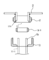
図3はユニオン接手の構造を説明するための図で、図3(a)は部品構成の断面模式図、図3(b)は連結後の断面模式図である。図3に見られるように、ユニオン接手はつば付きユニオン管11、雄ネジ部17が外周に形成されたユニオンネジ12、内面に雌ネジ部18が形成されたユニオンナット13、及び第1パッキング14(例えばオーリング)から構成される。
Figure 3 is a diagram for explaining the structure of the union joint, where Figure 3(a) is a schematic cross-sectional view of the component configuration, and Figure 3(b) is a schematic cross-sectional view after connection. As can be seen in Figure 3, the union joint is composed of a
つば付きユニオン管11は、一方の直管部15aの先端につば状突起部16が設けられてなるものである。ユニオンネジ12は、直管部15bの外周に雄ネジ部17が形成されてなる。ユニオンナット13はリング状の部品で、その内面に雌ネジ部18(ユニオンネジ12の雄ネジ部17と螺号する)及び肩部19が形成されている。
The
つば付きユニオン管11とユニオンネジ12の先端面を、第1パッキング14を挟んで、突き合わせた状態で、ユニオンナット13の雌ネジ部18をユニオンネジ12の雄ネジ部17に螺号させて、ネジを締めてゆくと、ユニオンナット13の肩部19が、つば状突起部16を背面から押圧することになり、これにより両直管部の接合面の第1パッキング14が押し付けられて、気密又は水密が保持されることになる。
When the tip faces of the
なお、ユニオンナット13の胴部20は、ネジの締め込みが容易になるような形状になっている。例えば、ユニオンナット13の径が大きい場合には、胴部20は円筒状で、その外周全面に幅5mm程度の縦溝が形成され、滑り止めの機能を果たすように構成されている。また、ユニオンナット13の径が小さい場合には、スパナ等で締め込みやすいように、ユニオンナットの胴部20は、六角柱の形状になっている。
The
図4は、本発明の第一実施例で、筒型隔膜電極1と上部連通タンク7とをユニオン接手で連結する連結部の構造を示す断面模式図である。上部連通タンク底板21の孔部には、つば付きユニオン管11の直管部15aが接合され、その先端につば状突起部16が取り付けられている。ユニオンナット13は、直管部15aが接合される前につば付きユニオン管の外周に装着されている。本明細書において、つば付きユニオン管11とユニオンナット13との組合せをA連結部材と称する。
Figure 4 is a cross-sectional schematic diagram showing the structure of the connection part that connects the
筒型隔膜電極1の上端には、雄ネジ部17が形成されているユニオンネジ12の直管部15bが接合している。本明細書においては、かかるユニオンネジ12をC連結部材と称する。つば付きユニオン管11の先端と、A連結部材の先端を、第1パッキング14を挟んで突き合わせ、ユニオンナット13を締め込めば、筒型隔膜電極1が上部連通タンクの底面に水密かつ着脱可能に連結される。
The
同様に下部連通タンク上板22の孔部には、つば付きユニオン管11の直管部15aが溶接されており、ユニオンナット13が直管部15aが溶接される前につば付きユニオン管の外周に装着されている。筒型隔膜電極1の下端は、雄ネジ部17が形成されているユニオンネジ12の直管部15bが固着している。A連結部材の先端と、C連結部材の先端を、第1パッキング14を挟んで突き合わせ、ユニオンナット13を締め込めば、筒型隔膜電極1が下部連通タンクの底面に水密かつ着脱可能に連結されることになる。なお、筒型隔膜電極1は、その剛性が必ずしも高くないので、取り付け、取り外しの際に、ある程度の撓みを持たせることができる。したがって、上部連通タンク7と下部連通タンク8の間隔が固定されていても、筒型隔膜電極の着脱が可能である。
Similarly, the
図5は、本発明の一実施例における筒型隔膜電極の構造を示す図である。図5に見られるように、筒型隔膜電極1の上部取り付け部5、下部取り付け部6には、ユニオンネジ12(C連結部材)が接合されている。図6は、本発明の一実施例で筒型隔膜電極1が上下連通タンクに連結された状態を示す図である。図6は、図5に示す筒型隔膜電極1の両端にはユニオンネジ12が接合(固着)され、上部連通タンクの取り付け部と下部連通タンクの取り付け部にはA連結部材の直管部15aが溶接されており、ユニオンネジ12とA連結部材とを第1パッキング14を介在させ、ユニオンナット13を締め込むことで筒型隔膜電極1が上下連通タンクに水密に接合している状態を示している。
Figure 5 is a diagram showing the structure of a cylindrical diaphragm electrode in one embodiment of the present invention. As shown in Figure 5, a union screw 12 (C connecting member) is joined to the upper mounting
図7は、本発明の第二の実施例における筒型隔膜電極1と上部連通タンク7とをユニオン接手で連結する連結部の構造を示す断面模式図である。図4に示す筒型隔膜電極1と上部連通タンク、下部連通タンクとをユニオン接手で連結する連結部の構造と、図7に示すそれらの連結部の構造の相違について説明する。
Figure 7 is a schematic cross-sectional view showing the structure of the connection part that connects the
図7(a)は部品構成の断面模式図、図7(b)は連結後の断面模式図である。図7に示すように、第二の実施例のユニオン接手は、つば無しユニオン管11―1、ユニオンネジ12、ユニオンナット13及び第2パッキング14―1とから構成される。
Figure 7(a) is a schematic cross-sectional view of the component configuration, and Figure 7(b) is a schematic cross-sectional view after connection. As shown in Figure 7, the union joint of the second embodiment is composed of a flangeless union pipe 11-1, a
ここで、つば無しユニオン管11―1は、直管部15aのみからなり、実施例1のように直管部15aの先端につば状突起部16が設けられていない。第2パッキング14-1は、ゴム等を材料とする所定の幅を有するリング形状の弾性体であり、その両周縁には所定の長さのテーパが形成されている。
Here, the flangeless union pipe 11-1 consists only of a
第2パッキング14-1は、つば無しユニオン管11-1の直管部15aに挿通され、直管部15aを締付て密着し、その摩擦力で所望の位置に固定されている。このため、容易に所定の位置からずれることはないが、第2パッキング14-1と直管部15aとの摩擦力を上回る力、例えばユニオンナット13の回旋による締め込み力により、第2パッキング14-1の位置がずれる(変わる)。
The second packing 14-1 is inserted into the
ユニオンナット13をユニオンネジ12に螺号させ締め込むことで、第2パッキング14-1の端部はユニオンネジ12に密着するなかで少しずつ、ずれながらユニオンナット13の肩部19と当接密着する。第2パッキング14-1と当接するユニオンネジの直管部15bの端部、及びユニオンナット13の肩部19は、第2パッキング14-1のテーパと、それぞれ密着して当接するように反対方向のテーパが形成されている。
By screwing the
図8は、本発明の第二の実施例における上部連通タンク7の孔部にユニオンネジ12(C連結部材)の直管部15bを溶着し、筒型隔膜電極1の端部に、B連結部材のつば無しユニオン管11―1の直管部15aを固着し、C連結部材とB連結部材とにより上部連通タンク7と筒型隔膜電極1とを連結する構造を示す断面模式図である。上部連通タンク底板21の孔部には、雄ネジ部17が形成されているユニオンネジ12の他端が接合されている。
Figure 8 is a schematic cross-sectional view showing a structure in which the
筒型隔膜電極1の両端には、つば無しユニオン管11―1である直管部15aが接合されている。ユニオンナット13は、つば無しユニオン管11-1の外周に装着されている。本明細書においては、つば無しユニオン管11―1とユニオンナット13との組合せをB連結部材と称する。
A
リング状のパッキング14-1は、つば無しユニオン管11-1(直管部15a)挿通され、直管部15aに所定の位置で密着固定する。第2パッキング14-1の一端はユニオンナット13の肩部19と当接密着する。直管部15aをユニオンネジ12に嵌入し、ユニオンナット13を締め込めば、ユニオンネジ12の雄ネジ部17とユニオンナット13の雌ネジ部18との螺合により、リング状の第2パッキング14-1に形成されているテーパ部が、ユニオンナット13の肩部19、直管部15bのテーパ部と当接密着し、極液の漏れを防止する。筒型隔膜電極を下部連通タンクに連結する方法も、上記と全く同様である。第2パッキング14-1の直管部15aの位置(設置位置)が、ユニオンナット13の回旋(締め込み)により、直管部15aに密着するなかでずれるため、製造時における筒型隔膜電極の長さのばらつきを調整することができる。
The ring-shaped packing 14-1 is inserted into the flangeless union pipe 11-1 (
第二の実施例の着脱可能な連結構造は、第一の実施例の着脱可能な連結構造よりも、筒型隔膜電極の製造時におけるバラつきを調整できるという顕著な効果がある。また、第一の実施例の連結構造よりも、筒型隔膜電極1に与えるストレス(引張力)を軽減できるという利点がある。
The detachable connection structure of the second embodiment has a more significant effect than the detachable connection structure of the first embodiment in that it can adjust variations that occur during the manufacture of the cylindrical diaphragm electrode. It also has the advantage of being able to reduce the stress (tensile force) applied to the
第一の実施例の連結構造は、オーリングである第1パッキング14を挟んで、つば状突起部16と雄ネジ部17とを突き合わせ、ユニオンナット13を締め込むことで連結し、水密性を確保している。このため、筒型隔膜電極の長さは取替前のものと取り替えるものとがほぼ同じ長さでないと取り替えることができない。例えば、取替前の筒型隔膜電極よりも短い場合には、ユニオンナット13の締め込みにより、筒型並列電極が延長される。また、オーリングが圧縮され縮むので、これらが筒型隔膜電極1への引張力となる悪影響を及ぼす。
The connection structure of the first embodiment ensures watertightness by butting the flange-shaped
これに対して、第二の実施例による着脱可能な連結構造は、上述したように両端周縁にテーパが形成されたリング状の第2パッキング14-1に直管部15bが挿通され、ユニオンナット13を締め込むことでリング状の第2パッキング14-1が少しずつづれて、ユニオンナット13の肩部19のテーパ部に当接密着するとともに、ユニオンネジ12の直管部15bの端部に形成された逆テーパ部に当接密着する構造となっている。このため、筒型隔膜電極1の長さにバラつきがあっても、そのバラつきがリング状の第2パッキング14-1のずれにより調整される。また、ユニオンナット13の締め込みによる筒型隔膜電極1に引張力がかからないことから、筒型隔膜電極1にかかるストレス(引張力)が軽減される。
In contrast, in the detachable connection structure according to the second embodiment, the
即ち、第二の実施例の連結構造では、第2パッキング14-1の直管部15aに挿通密着させる位置がユニオンナット13の回旋により変わるので、筒型隔膜電極1の製造時の長さのバラつきがこれにより調整できる。また、第2パッキング14-1と直管部15bと肩部19との当接部はテーパが形成されていることから、当接部の面積が大きくなり、ユニオンナット13の締め込みにより当接部の第2パッキング14-1は横方向に広がることでより確実な水密性が確保できる。
That is, in the connection structure of the second embodiment, the position where the second packing 14-1 is inserted into the
図9は、本発明の第一の実施例、第二の実施例に示すA連結部材、B連結部材、C連結部材を組合せて、筒型隔膜電極1を上部連通タンク7、下部連通タンク8に水密かつ着脱可能に連結する組合せを示した図である。
図9(a)は、上部連通タンク7の孔部にA連結部材の直管部15aを溶接し、筒型隔膜電極1の上部取り付け部5には、その一端にA連結部材のユニオンナット13の内側に形成されている雄ネジ部18と螺号する雄ネジ部17が形成されているC連結部材の他端が固着されている。A連結部材とC連結部材との間に第1パッキング14を介在させ、A連結部材のユニオンナット13を締め込むことにより、上部連通タンク7と筒型隔膜電極1の上部とが水密かつ着脱可能に連結する。
FIG. 9 is a diagram showing a combination of the A connecting member, B connecting member, and C connecting member shown in the first and second embodiments of the present invention, in which the
9(a), the
下部連通タンク8の孔部にはC連結部材の直管部15bが溶接されている。筒型隔膜電極1の下部取り付け部6には、その一端にC連結部材の雄ネジ部17と螺号する雄ネジ部18が形成されているA連結部材又はB連結部材の他端である直管部15aが固着されている。A連結部材が固着されている場合は、A連結部材とC連結部材との間に第1パッキング14を介在させ、ユニオンナット13を締め込むことにおり、下部連通タンク8と筒型隔膜電極1とが、水密かつ着脱可能に連結する。B連結部材が固着されている場合は、B連結部材とC連結部材との間に第2パッキング14-1を介在させ、B連結部材のユニオンナット13を締め込むことにより、下部連通タンク8と筒型隔膜電極1の下部とが水密かつ着脱可能の連結する。
The
図9(b)は、上部連通タンク7の孔部にはB連結部材の直管部15aが溶接されている。筒型隔膜電極1の上部取り付け部5には、一端にB連結部材のユニオンナット13の内側に形成されている雄ネジ部18と螺号する雄ネジ部17が形成されているC連結部材の他端が固着されている。B連結部材とC連結部材との間に第2パッキング14―1を介在させ、B連結部材のユニオンナット13を締め込むことにより、上部連通タンク7と筒型隔膜電極1の上部とが水密かつ着脱可能に連結する。
In Figure 9(b), the
下部連通タンク8の孔部にはC連結部材の直管部15bが溶接されている。筒型隔膜電極1の下部取り付け部6には、一端にC連結部材の雄ネジ部17と螺号する雄ネジ部18が形成されているA連結部材又はB連結部材の他端である直管部15aが固着されている。A連結部材が固着されている場合は、A連結部材とC連結部材との間に第1パッキング14を介在させ、ユニオンナット13を締め込むことにおり、下部連通タンク8と筒型隔膜電極1とが、水密かつ着脱可能に連結する。B連結部材が固着されている場合は、B連結部材とC連結部材との間にパッキング2を介在させ、B連結部材のユニオンナット13を締め込むことにより、下部連通タンク8と筒型隔膜電極1の下部とが水密かつ着脱可能の連結する。
The
図9(c)は、上部連通タンク7の孔部にはC連結部材の端部が溶接されている。筒型隔膜電極1の上部取り付け部5には、その一端にC連結部材の雄ネジ部17と螺号する雄ネジ部18が形成されているユニオンナット13を構成要素とするA連結部材又はB連結部材の直管部15aが固着されている。A連結部材の場合は、A連結部材とC連結部材との間に第1パッキング14を介在させ、B連結部材の場合は、B連結部材とC連結部材の間に第2パッキング14-1を介在させ、ユニオンナット13を締め込むことにより、上部連通タンク7と筒型隔膜電極1の上部とが水密かつ着脱可能に連結する。
In Figure 9(c), the end of the C connecting member is welded to the hole in the
下部連通タンク8の孔部にはA連結部材の直管部15aが溶接されている。筒型隔膜電極1の下部取り付け部6には、その一端にA連結部材の雄ネジ部18と螺号する雄ネジ部17が形成されているC連結部材の他端が固着されている。A連結部材とC連結部材との間に第1パッキングを介在させ、ユニオンナット13を締め込むことにおり、下部連通タンク8と筒型隔膜電極1の下部とが、水密かつ着脱可能に連結する。
The
図9(d)は、上部連通タンク7の孔部にC連結部材の端部が溶接されている。筒型隔膜電極1の上部取り付け部5には、その一端にC連結部材の雄ネジ部17と螺号する雄ネジ部18が形成されているユニオンナット13を構成要素とするA連結部材又はB連結部材の直管部15aが固着されている。A連結部材の場合は、A連結部材とC連結部材との間に第1パッキング14を介在させ、B連結部材の場合は、B連結部材とC連結部材の間に第2パッキング14-1を介在させ、ユニオンナット13を締め込むことにより、上部連通タンク7と筒型隔膜電極1の上部とが水密かつ着脱可能に連結する。
In Figure 9(d), the end of the C connecting member is welded to the hole in the
下部連通タンク8の孔部にはB連結部材の直管部15aが溶接されている。筒型隔膜電極1の下部取り付け部6には、一端にA連結部材の雄ネジ部18と螺号する雄ネジ部17が形成されているC連結部材の一端が固着されている。B連結部材とC連結部材との間に第2パッキング14-1を介在させ、ユニオンナット13を締め込むことにおり、下部連通タンク8と筒型隔膜電極1の下部とが、水密かつ着脱可能に連結する。
The
図9に示すA連結部材、B連結部材、C連結部材と、第1パッキング14,第2パッキング14-1の組合せの他、筒型隔膜電極1を上部連通タンク7、下部連通タンク8に水密かつ着脱可能に連結する組合せは、都合、16通りある。いずれの組合せであっても上下連通タンクと筒型隔膜電極とを水密かつ着脱可能に連結することができるが、上部連通タンク7と筒型隔膜電極1の上部との接合をA連結部材とC連結部材で連結した場合は、下部連通タンク8と筒型隔膜電極1の下部とをB連結部材とC連結部材で連結することが好適である。これは、A連結部材とC連結部材で連結し上部を固定しておき、自由度のあるB連結部材を下部に用いることにより、筒型隔膜電極をスムースに着脱することができるからである。
In addition to the combination of the A connecting member, B connecting member, and C connecting member with the
図10は、本発明の筒型並列電極と従来の筒型並列電極との輸送時における梱包面積の比較図である。従来の4列の筒型並列電極の梱包面積は、隔膜の乾燥を防ぐための保湿梱包ともに、約1.1平方メートルとなる。 Figure 10 is a comparison diagram of the packaging area during transportation between the cylindrical parallel electrodes of the present invention and conventional cylindrical parallel electrodes. The packaging area of the conventional four-row cylindrical parallel electrodes, including the moisturizing packaging to prevent the diaphragm from drying out, is approximately 1.1 square meters.
これに対して、本発明による筒型隔膜電極の着脱可能な筒型並列電極の保湿梱包面積は約0.48平方メートルとなり、保湿梱包面積が従来技術に比較して約半分の面積となる。これにより、筒型並列電極を電極製造工場から、遠隔地の電解メッキ工場に輸送する際に、筒型隔膜電極を束ねて梱包し、これと上下連通タンクが分離した状態で輸送し、メッキ工場において組立を行うことができ、梱包費及び輸送費を大幅に軽減することができる。 In contrast, the moisturizing packaging area of the removable cylindrical parallel electrodes of the cylindrical diaphragm electrode of the present invention is approximately 0.48 square meters, which is approximately half the moisturizing packaging area compared to the conventional technology. As a result, when the cylindrical parallel electrodes are transported from the electrode manufacturing factory to a remote electrolytic plating factory, the cylindrical diaphragm electrodes can be bundled and packaged, and the upper and lower communicating tanks can be transported separately, and assembly can be performed at the plating factory, which allows for a significant reduction in packaging and transportation costs.
1:筒型隔膜電極、2:電極本体、2-1:芯材、3:イオン交換膜、4:保護膜、
5:上部取り付け部、6:下部取り付け部、7:上部連通タンク、8:下部連通タンク、9:給電端子、10:フランジ、11:つば付きユニオン管、11―1:つば無しユニオン管、12:ユニオンネジ(C連結部材)、13:ユニオンナット、14:第1パッキング、14―1:第2パッキング、15a,15b:直管部、16:つば状突起部、17:雄ネジ部、18:雌ネジ部、19:肩部、20:胴部、21:上部連通タンク底板、22:下部連通タンク上板
1: cylindrical diaphragm electrode, 2: electrode body, 2-1: core material, 3: ion exchange membrane, 4: protective membrane,
5: upper mounting part, 6: lower mounting part, 7: upper communicating tank, 8: lower communicating tank, 9: power supply terminal, 10: flange, 11: flanged union pipe, 11-1: flangeless union pipe, 12: union screw (C connecting member), 13: union nut, 14: first packing, 14-1: second packing, 15a, 15b: straight pipe section, 16: flange-shaped protrusion, 17: male thread section, 18: female thread section, 19: shoulder section, 20: body section, 21: upper communicating tank bottom plate, 22: lower communicating tank top plate
Claims (6)
一端につばを備えた直管のつば付きユニオン管と、前記つば付きユニオン管の外周に摺動可能に装着され、内側に雌ネジが形成されたユニオンナットとを備えるA連結部材と、
直管のつば無しユニオン管と、前記つば無しユニオン管の外周に摺動可能に装着され、内側に雌ネジが形成されたユニオンナットとを備えるB連結部材と、
一端の外周に前記雌ネジと螺号する雄ネジが形成されたC連結部材と、
前記A連結部材と前記C連結部材との間に介装される第1パッキングと、
前記つば無しユニオン管の所望の位置に装着される第2パッキングとを有し、
前記A連結部材の他端又は前記B連結部材の他端が、前記上部連通タンクの孔部と前記下部連通タンクの孔部に溶接され、
前記C連結部材の他端が、前記筒型隔膜電極の両端にそれぞれ固着され、
前記ユニオンナットの回旋により前記筒型隔膜電極が着脱可能に構成されていることを特徴とする筒型並列電極。 In a cylindrical parallel electrode system, a plurality of cylindrical diaphragm electrodes are watertightly and detachably connected to an upper communicating tank and a lower communicating tank through which an electrode liquid flows,
A connecting member A includes a flanged union pipe that is a straight pipe with a flange at one end, and a union nut that is slidably attached to the outer periphery of the flanged union pipe and has a female thread formed on the inside;
A B connecting member including a straight flangeless union pipe and a union nut slidably attached to the outer periphery of the flangeless union pipe and having a female thread formed on the inside;
A C-shaped connecting member having a male screw formed on the outer periphery of one end thereof, the male screw engaging with the female screw;
A first packing is interposed between the A connecting member and the C connecting member;
and a second packing attached to a desired position of the flangeless union pipe.
the other end of the A connecting member or the other end of the B connecting member is welded to a hole portion of the upper communication tank and a hole portion of the lower communication tank,
The other ends of the C-shaped connecting members are fixed to both ends of the cylindrical diaphragm electrode,
4. The cylindrical parallel electrodes, wherein the cylindrical diaphragm electrode is configured to be detachable by rotating the union nut.
一端につばを備えた直管のつば付きユニオン管と、前記つば付きユニオン管の外周に摺動可能に装着され、内側に雌ネジが形成されたユニオンナットとを備えるA連結部材と、
直管のつば無しユニオン管と、前記つば無しユニオン管の外周に摺動可能に装着され、内側に雌ネジが形成されたユニオンナットとを備えるB連結部材と、
一端の外周に前記雌ネジと螺号する雄ネジが形成されたC連結部材と、
前記A連結部材と前記C連結部材との間に介装される第1パッキングと、
前記つば無しユニオン管の所望の位置に装着される第2パッキングとを有し、
前記A連結部材の他端又は前記B連結部材の他端が、前記筒型隔膜電極の両端にそれぞれ固着され、
前記上部連通タンクの孔部と前記下部連通タンクの孔部に前記C連結部材の他端がそれぞれ溶接され、
前記ユニオンナットの回旋により前記筒型隔膜電極が着脱可能に構成されていることを備えたことを特徴とする筒型並列電極。 In a cylindrical parallel electrode system, a plurality of cylindrical diaphragm electrodes are watertightly and detachably connected to an upper communicating tank and a lower communicating tank through which an electrode liquid flows,
A connecting member A includes a flanged union pipe that is a straight pipe with a flange at one end, and a union nut that is slidably attached to the outer periphery of the flanged union pipe and has a female thread formed on the inside;
A B connecting member including a straight flangeless union pipe and a union nut slidably attached to the outer periphery of the flangeless union pipe and having a female thread formed on the inside;
A C-shaped connecting member having a male screw formed on the outer periphery of one end thereof, the male screw engaging with the female screw;
A first packing is interposed between the A connecting member and the C connecting member;
and a second packing attached to a desired position of the flangeless union pipe.
the other end of the A connecting member or the other end of the B connecting member is fixed to both ends of the cylindrical diaphragm electrode,
the other end of the C-shaped connecting member is welded to the hole of the upper communication tank and the hole of the lower communication tank,
The cylindrical parallel electrode is configured so that the cylindrical diaphragm electrode can be attached and detached by turning the union nut.
一端につばを備えた直管のつば付きユニオン管と、前記つば付きユニオン管の外周に摺動可能に装着され、内側に雌ネジが形成されたユニオンナットとを備えるA連結部材と、
直管のつば無しユニオン管と、前記つば無しユニオン管の外周に摺動可能に装着され、内側に雌ネジが形成されたユニオンナットとを備えるB連結部材と、
一端の外周に前記雌ネジと螺号する雄ネジが形成されたC連結部材と、
前記A連結部材と前記C連結部材との間に介装される第1パッキングと、
前記つば無しユニオン管の所望の位置に装着される第2パッキングとを有し、
前記A連結部材の他端又は前記B連結部材の他端が、前記上部連通タンクの孔部に溶接され、前記C連結部材の他端が前記下部連通タンクの孔部に溶接され、前記筒型隔膜電極の上端に前記C連結部材の他端が固着され、下端に前記A連結部材の他端又は前記B連結部材の他端が固着され、
前記ユニオンナットの回旋により前記筒型隔膜電極が着脱可能に構成されていることを特徴とする筒型並列電極。 In a cylindrical parallel electrode system, a plurality of cylindrical diaphragm electrodes are watertightly and detachably connected to an upper communicating tank and a lower communicating tank through which an electrode liquid flows,
A connecting member A includes a flanged union pipe that is a straight pipe with a flange at one end, and a union nut that is slidably attached to the outer periphery of the flanged union pipe and has a female thread formed on the inside;
A B connecting member including a straight flangeless union pipe and a union nut slidably attached to the outer periphery of the flangeless union pipe and having a female thread formed on the inside;
A C-shaped connecting member having a male screw formed on the outer periphery of one end thereof, the male screw engaging with the female screw;
A first packing is interposed between the A connecting member and the C connecting member;
and a second packing attached to a desired position of the flangeless union pipe.
the other end of the A connecting member or the other end of the B connecting member is welded to a hole of the upper communicating tank, the other end of the C connecting member is welded to a hole of the lower communicating tank, the other end of the C connecting member is fixed to an upper end of the cylindrical diaphragm electrode, and the other end of the A connecting member or the other end of the B connecting member is fixed to a lower end of the cylindrical diaphragm electrode,
4. The cylindrical parallel electrodes, wherein the cylindrical diaphragm electrode is configured to be detachable by rotating the union nut.
一端につばを備えた直管のつば付きユニオン管と、前記つば付きユニオン管の外周に摺動可能に装着され、内側に雌ネジが形成されたユニオンナットとを備えるA連結部材と、
直管のつば無しユニオン管と、前記つば無しユニオン管の外周に摺動可能に装着され、内側に雌ネジが形成されたユニオンナットとを備えるB連結部材と、
一端の外周に前記雌ネジと螺号する雄ネジが形成されたC連結部材と、
前記A連結部材と前記C連結部材との間に介装される第1パッキングと、
前記つば無しユニオン管の所望の位置に装着される第2パッキングとを有し、
前記C連結部材の他端が前記上部連通タンクの孔部に溶接され、前記下部連通タンクの孔部に前記A連結部材の他端又はB連結部材の他端が溶接され、
前記筒型隔膜電極の上端に前記A連結部材の他端又はB連結部材の他端が固着され、下端に前記C連結部材の他端が固着され、
前記ユニオンナットの回旋により前記筒型隔膜電極が着脱可能に構成されていることを特徴とする筒型並列電極。 In a cylindrical parallel electrode system, a plurality of cylindrical diaphragm electrodes are watertightly and detachably connected to an upper communicating tank and a lower communicating tank through which an electrode liquid flows,
A connecting member A includes a flanged union pipe that is a straight pipe with a flange at one end, and a union nut that is slidably attached to the outer periphery of the flanged union pipe and has a female thread formed on the inside;
A B connecting member including a straight flangeless union pipe and a union nut slidably attached to the outer periphery of the flangeless union pipe and having a female thread formed on the inside;
A C-shaped connecting member having a male screw formed on the outer periphery of one end thereof, the male screw engaging with the female screw;
A first packing is interposed between the A connecting member and the C connecting member;
and a second packing attached to a desired position of the flangeless union pipe.
the other end of the C connecting member is welded to the hole of the upper communication tank, and the other end of the A connecting member or the other end of the B connecting member is welded to the hole of the lower communication tank,
The other end of the A connecting member or the other end of the B connecting member is fixed to the upper end of the cylindrical diaphragm electrode, and the other end of the C connecting member is fixed to the lower end of the cylindrical diaphragm electrode,
4. The cylindrical parallel electrodes, wherein the cylindrical diaphragm electrode is configured to be detachable by rotating the union nut.
前記筒型並列電極のそれぞれに電解用電力を供給する給電手段
とを備えたことを特徴とする電解メッキ装置。 a plurality of cylindrical parallel electrodes according to claim 1 or 2 arranged in an electrolytic cell; and an electrode solution circulating means for circulating the electrode solution from the upper communicating tank to the lower communicating tank;
and a power supply means for supplying power for electrolysis to each of said cylindrical parallel electrodes.
前記筒型並列電極のそれぞれに電解用電力を供給する給電手段とを備えたことを特徴とする電解メッキ装置。 a plurality of cylindrical parallel electrodes according to claim 3 or 4 arranged in an electrolytic cell; and an electrode solution circulating means for circulating the electrode solution from the upper communicating tank to the lower communicating tank;
and a power supply means for supplying power for electrolysis to each of said cylindrical parallel electrodes.
Priority Applications (1)
| Application Number | Priority Date | Filing Date | Title |
|---|---|---|---|
| JP2023121192A JP7549397B1 (en) | 2023-07-26 | 2023-07-26 | Cylindrical parallel electrodes and electrolytic plating device using same |
Applications Claiming Priority (1)
| Application Number | Priority Date | Filing Date | Title |
|---|---|---|---|
| JP2023121192A JP7549397B1 (en) | 2023-07-26 | 2023-07-26 | Cylindrical parallel electrodes and electrolytic plating device using same |
Publications (2)
| Publication Number | Publication Date |
|---|---|
| JP7549397B1 true JP7549397B1 (en) | 2024-09-11 |
| JP2025017873A JP2025017873A (en) | 2025-02-06 |
Family
ID=92673210
Family Applications (1)
| Application Number | Title | Priority Date | Filing Date |
|---|---|---|---|
| JP2023121192A Active JP7549397B1 (en) | 2023-07-26 | 2023-07-26 | Cylindrical parallel electrodes and electrolytic plating device using same |
Country Status (1)
| Country | Link |
|---|---|
| JP (1) | JP7549397B1 (en) |
Citations (4)
| Publication number | Priority date | Publication date | Assignee | Title |
|---|---|---|---|---|
| JP2001324067A (en) | 2000-05-15 | 2001-11-22 | Sekisui Chem Co Ltd | Union fitting |
| JP2006169552A (en) | 2004-12-13 | 2006-06-29 | Astom:Kk | Ion exchange membrane / electrode assembly |
| CN206768233U (en) | 2017-05-31 | 2017-12-19 | 李彦廉 | A kind of brown gas generator for car combustion engine |
| JP2022164691A (en) | 2016-08-15 | 2022-10-27 | バロン ホルヘ ガルセス | Electrolysis cell in the form of capacitor of cylindrical plate |
-
2023
- 2023-07-26 JP JP2023121192A patent/JP7549397B1/en active Active
Patent Citations (4)
| Publication number | Priority date | Publication date | Assignee | Title |
|---|---|---|---|---|
| JP2001324067A (en) | 2000-05-15 | 2001-11-22 | Sekisui Chem Co Ltd | Union fitting |
| JP2006169552A (en) | 2004-12-13 | 2006-06-29 | Astom:Kk | Ion exchange membrane / electrode assembly |
| JP2022164691A (en) | 2016-08-15 | 2022-10-27 | バロン ホルヘ ガルセス | Electrolysis cell in the form of capacitor of cylindrical plate |
| CN206768233U (en) | 2017-05-31 | 2017-12-19 | 李彦廉 | A kind of brown gas generator for car combustion engine |
Also Published As
| Publication number | Publication date |
|---|---|
| JP2025017873A (en) | 2025-02-06 |
Similar Documents
| Publication | Publication Date | Title |
|---|---|---|
| US11283098B2 (en) | System for high-temperature tight coupling of a stack having SOEC/SOFC-type solid oxides | |
| JP6114407B2 (en) | ELECTROLYSIS DEVICE AND ITS MANUFACTURING METHOD | |
| US9920440B2 (en) | Electrochemical stack device | |
| US20080169648A1 (en) | Pipe coupling | |
| US9410257B2 (en) | Tubular electrochemical cell | |
| JP2006009969A (en) | Flow path block for accumulated gas control device and its manufacturing method and accumulated gas control device | |
| KR102436790B1 (en) | pressure sensor | |
| JP7549397B1 (en) | Cylindrical parallel electrodes and electrolytic plating device using same | |
| WO2016117264A1 (en) | Redox-flow battery | |
| JPH10208766A (en) | Redox flow battery | |
| JPS5827990A (en) | Method of assembling filter press type electrolytic cell | |
| US9318767B2 (en) | Laminate assembly sealing method and arrangement | |
| JP2009004254A (en) | Assembly method of fuel cell stack | |
| US20250354276A1 (en) | Framing Structure For An Electrolyser | |
| JP3723116B2 (en) | Solid polymer membrane water electrolyzer | |
| JPH08312846A (en) | Sealing retaining wall for pipe-shaped member, sealing method, fluid part with the retaining wall, and fluid device with the fluid part | |
| JP3487696B2 (en) | Hydrogen / oxygen generator | |
| EP2469637B1 (en) | Laminate assembly sealing method and arrangement | |
| TWI913547B (en) | Framing structure for an electrolyser, electrochemical cell and the electrolyser for high pressure water electrolysis | |
| CN207160144U (en) | Compressed tanks and non-tower water feeder | |
| DK182087B1 (en) | An electrolysis cell stack, a method for detecting a leak and use of an electrolysis cell stack | |
| CN223468458U (en) | Flange type electrolytic tank medium inlet and outlet structure | |
| JPH0515320U (en) | Stacked secondary battery | |
| US20250333858A1 (en) | High pressure gasket for an electrolysis device | |
| US20220243846A1 (en) | Rotational fitting for low purity, high purity, and ultra high purity gas lines or process cooling and critical process cooling water systems |
Legal Events
| Date | Code | Title | Description |
|---|---|---|---|
| A621 | Written request for application examination |
Free format text: JAPANESE INTERMEDIATE CODE: A621 Effective date: 20240304 |
|
| A871 | Explanation of circumstances concerning accelerated examination |
Free format text: JAPANESE INTERMEDIATE CODE: A871 Effective date: 20240304 |
|
| A131 | Notification of reasons for refusal |
Free format text: JAPANESE INTERMEDIATE CODE: A131 Effective date: 20240610 |
|
| A521 | Request for written amendment filed |
Free format text: JAPANESE INTERMEDIATE CODE: A523 Effective date: 20240612 |
|
| TRDD | Decision of grant or rejection written | ||
| A01 | Written decision to grant a patent or to grant a registration (utility model) |
Free format text: JAPANESE INTERMEDIATE CODE: A01 Effective date: 20240801 |
|
| A61 | First payment of annual fees (during grant procedure) |
Free format text: JAPANESE INTERMEDIATE CODE: A61 Effective date: 20240823 |
|
| R150 | Certificate of patent or registration of utility model |
Ref document number: 7549397 Country of ref document: JP Free format text: JAPANESE INTERMEDIATE CODE: R150 |