JP7547595B2 - Information input device, method, and program - Google Patents
Information input device, method, and program Download PDFInfo
- Publication number
- JP7547595B2 JP7547595B2 JP2023192781A JP2023192781A JP7547595B2 JP 7547595 B2 JP7547595 B2 JP 7547595B2 JP 2023192781 A JP2023192781 A JP 2023192781A JP 2023192781 A JP2023192781 A JP 2023192781A JP 7547595 B2 JP7547595 B2 JP 7547595B2
- Authority
- JP
- Japan
- Prior art keywords
- external device
- driver
- communication
- information
- pen
- Prior art date
- Legal status (The legal status is an assumption and is not a legal conclusion. Google has not performed a legal analysis and makes no representation as to the accuracy of the status listed.)
- Active
Links
Images


Classifications
-
- G—PHYSICS
- G06—COMPUTING OR CALCULATING; COUNTING
- G06F—ELECTRIC DIGITAL DATA PROCESSING
- G06F13/00—Interconnection of, or transfer of information or other signals between, memories, input/output devices or central processing units
- G06F13/38—Information transfer, e.g. on bus
- G06F13/40—Bus structure
- G06F13/4063—Device-to-bus coupling
- G06F13/4068—Electrical coupling
- G06F13/4072—Drivers or receivers
-
- G—PHYSICS
- G06—COMPUTING OR CALCULATING; COUNTING
- G06F—ELECTRIC DIGITAL DATA PROCESSING
- G06F13/00—Interconnection of, or transfer of information or other signals between, memories, input/output devices or central processing units
- G06F13/38—Information transfer, e.g. on bus
- G06F13/42—Bus transfer protocol, e.g. handshake; Synchronisation
- G06F13/4282—Bus transfer protocol, e.g. handshake; Synchronisation on a serial bus, e.g. I2C bus, SPI bus
-
- G—PHYSICS
- G06—COMPUTING OR CALCULATING; COUNTING
- G06F—ELECTRIC DIGITAL DATA PROCESSING
- G06F3/00—Input arrangements for transferring data to be processed into a form capable of being handled by the computer; Output arrangements for transferring data from processing unit to output unit, e.g. interface arrangements
- G06F3/01—Input arrangements or combined input and output arrangements for interaction between user and computer
- G06F3/03—Arrangements for converting the position or the displacement of a member into a coded form
- G06F3/033—Pointing devices displaced or positioned by the user, e.g. mice, trackballs, pens or joysticks; Accessories therefor
- G06F3/0354—Pointing devices displaced or positioned by the user, e.g. mice, trackballs, pens or joysticks; Accessories therefor with detection of 2D relative movements between the device, or an operating part thereof, and a plane or surface, e.g. 2D mice, trackballs, pens or pucks
- G06F3/03545—Pens or stylus
-
- G—PHYSICS
- G06—COMPUTING OR CALCULATING; COUNTING
- G06F—ELECTRIC DIGITAL DATA PROCESSING
- G06F3/00—Input arrangements for transferring data to be processed into a form capable of being handled by the computer; Output arrangements for transferring data from processing unit to output unit, e.g. interface arrangements
- G06F3/01—Input arrangements or combined input and output arrangements for interaction between user and computer
- G06F3/03—Arrangements for converting the position or the displacement of a member into a coded form
- G06F3/033—Pointing devices displaced or positioned by the user, e.g. mice, trackballs, pens or joysticks; Accessories therefor
- G06F3/0354—Pointing devices displaced or positioned by the user, e.g. mice, trackballs, pens or joysticks; Accessories therefor with detection of 2D relative movements between the device, or an operating part thereof, and a plane or surface, e.g. 2D mice, trackballs, pens or pucks
- G06F3/03547—Touch pads, in which fingers can move on a surface
-
- G—PHYSICS
- G06—COMPUTING OR CALCULATING; COUNTING
- G06F—ELECTRIC DIGITAL DATA PROCESSING
- G06F3/00—Input arrangements for transferring data to be processed into a form capable of being handled by the computer; Output arrangements for transferring data from processing unit to output unit, e.g. interface arrangements
- G06F3/01—Input arrangements or combined input and output arrangements for interaction between user and computer
- G06F3/03—Arrangements for converting the position or the displacement of a member into a coded form
- G06F3/033—Pointing devices displaced or positioned by the user, e.g. mice, trackballs, pens or joysticks; Accessories therefor
- G06F3/038—Control and interface arrangements therefor, e.g. drivers or device-embedded control circuitry
- G06F3/0383—Signal control means within the pointing device
-
- G—PHYSICS
- G06—COMPUTING OR CALCULATING; COUNTING
- G06F—ELECTRIC DIGITAL DATA PROCESSING
- G06F3/00—Input arrangements for transferring data to be processed into a form capable of being handled by the computer; Output arrangements for transferring data from processing unit to output unit, e.g. interface arrangements
- G06F3/01—Input arrangements or combined input and output arrangements for interaction between user and computer
- G06F3/03—Arrangements for converting the position or the displacement of a member into a coded form
- G06F3/041—Digitisers, e.g. for touch screens or touch pads, characterised by the transducing means
- G06F3/0416—Control or interface arrangements specially adapted for digitisers
- G06F3/04162—Control or interface arrangements specially adapted for digitisers for exchanging data with external devices, e.g. smart pens, via the digitiser sensing hardware
-
- G—PHYSICS
- G06—COMPUTING OR CALCULATING; COUNTING
- G06F—ELECTRIC DIGITAL DATA PROCESSING
- G06F2213/00—Indexing scheme relating to interconnection of, or transfer of information or other signals between, memories, input/output devices or central processing units
- G06F2213/0042—Universal serial bus [USB]
Landscapes
- Engineering & Computer Science (AREA)
- Theoretical Computer Science (AREA)
- General Engineering & Computer Science (AREA)
- Physics & Mathematics (AREA)
- General Physics & Mathematics (AREA)
- Human Computer Interaction (AREA)
- Computer Hardware Design (AREA)
- Position Input By Displaying (AREA)
- User Interface Of Digital Computer (AREA)
- Information Transfer Systems (AREA)
Description
本発明は情報入力装置、方法、及びプログラムに関し、特に、PC(Personal Computer)又はスマートフォンに情報を入力するための情報入力装置、並びに、関連する方法及びプログラムに関する。 The present invention relates to an information input device, method, and program, and in particular to an information input device for inputting information into a PC (Personal Computer) or smartphone, and related methods and programs.
PCに情報を入力するための情報入力装置の一種であるペンタブレットは、パネル面上における電子ペンの位置を逐次検出し、PCに供給するよう構成された装置である。特許文献1には、この種のペンタブレットの例が開示されている。
A pen tablet, which is a type of information input device for inputting information into a PC, is a device that is configured to sequentially detect the position of an electronic pen on a panel surface and provide the position to the PC.
ところで、近年、PC及びスマートフォンなど複数のデバイスを1人で利用するマルチデバイス、並びに、Windows及びAndroidなど複数のOS(Operating System)を1人で利用するマルチOSの環境が進展しており、それに伴って、情報入力装置もマルチデバイス、マルチOSの環境に対応することが必要とされている。 In recent years, the trend toward multi-device environments in which one person uses multiple devices such as PCs and smartphones, and multi-OS environments in which one person uses multiple OSs (Operating Systems) such as Windows and Android, has progressed, and as a result, there is a need for information input devices to be compatible with multi-device and multi-OS environments.
したがって、本発明の目的の一つは、マルチデバイス、マルチOSの環境に対応する情報入力装置、方法、及びプログラムを提供することにある。 Therefore, one of the objects of the present invention is to provide an information input device, method, and program that is compatible with a multi-device, multi-OS environment.
本発明による情報入力装置は、第1のオペレーティングシステムにより動作する第1の外部機器及び第2のオペレーティングシステムにより動作する第2の外部機器のそれぞれと通信を行えるように構成された通信インタフェースと、前記第1の外部機器にデータを転送する場合には前記第1の外部機器で実行される第1のドライバに対応する第1のモードで動作し、前記第2の外部機器にデータを転送する場合には前記第1のドライバとは異なり前記第2の外部機器で実行される第2のドライバに対応する第2のモードで動作するコントローラと、を含むことを特徴とする。 The information input device according to the present invention is characterized by including a communication interface configured to communicate with each of a first external device operated by a first operating system and a second external device operated by a second operating system, and a controller that operates in a first mode corresponding to a first driver executed on the first external device when transferring data to the first external device, and operates in a second mode corresponding to a second driver different from the first driver and executed on the second external device when transferring data to the second external device.
本発明による方法は、通信インターフェイスが外部機器に接続されたことに応じて第1のモードで通信を開始する開始ステップと、前記開始ステップにより開始した通信の結果に基づき、通信相手の外部機器のオペレーティングシステムが前記第2のオペレーティングシステムであるか否かを判定する判定ステップと、前記判定ステップにより通信相手の外部機器のオペレーティングシステムが前記第2のオペレーティングシステムであると判定された場合に、前記第2のモードでの通信に切り替える切替ステップと、を含むことを特徴とする。 The method according to the present invention is characterized by including a start step of starting communication in a first mode in response to a communication interface being connected to an external device, a determination step of determining whether the operating system of the communication partner's external device is the second operating system based on the result of the communication started by the start step, and a switching step of switching to communication in the second mode when it is determined by the determination step that the operating system of the communication partner's external device is the second operating system.
本発明によるプログラムは、通信インターフェイスが外部機器に接続されたことに応じて第1のモードで通信を開始する開始ステップと、前記開始ステップにより開始した通信の結果に基づき、通信相手の外部機器のオペレーティングシステムが前記第2のオペレーティングシステムであるか否かを判定する判定ステップと、前記判定ステップにより通信相手の外部機器のオペレーティングシステムが前記第2のオペレーティングシステムであると判定された場合に、前記第2のモードでの通信に切り替える切替ステップと、をコンピュータに実行させるためのプログラムである。 The program according to the present invention is a program for causing a computer to execute a start step of starting communication in a first mode in response to a communication interface being connected to an external device, a determination step of determining whether the operating system of the communication partner external device is the second operating system based on the result of the communication started by the start step, and a switching step of switching to communication in the second mode when it is determined by the determination step that the operating system of the communication partner external device is the second operating system.
本発明によれば、マルチデバイス、マルチOSの環境に対応する情報入力装置、方法、及びプログラムを提供することが可能になる。 The present invention makes it possible to provide an information input device, method, and program that are compatible with a multi-device, multi-OS environment.
以下、添付図面を参照しながら、本発明の実施の形態について詳細に説明する。 The following describes in detail an embodiment of the present invention with reference to the attached drawings.
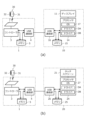
図1(a)は、本発明の実施の形態によるペンタブレット1をPC10に接続した状態を示す図であり、図1(b)は、本実施の形態によるペンタブレット1をスマートフォン20に接続した状態を示す図である。
Figure 1(a) is a diagram showing a
ペンタブレット1は、タッチ面を構成するタッチセンサ2を有して構成される。また、電子ペン30は、ペン型の端末(スタイラス)である。なお、電子ペン30は、例えばボールペンのようなインク滲出機能を有していてもよい。この場合のペンタブレット1は、タッチ面上に紙を載せた状態で使用される。
The
ペンタブレット1は、静電容量方式又は電磁誘導方式により、タッチ面上における電子ペン30の位置を示す座標を検出可能に構成される。また、電子ペン30は、それぞれのペン先に加わる力を示す筆圧値、それぞれに設けられるサイドスイッチのオンオフ状態を示すサイドスイッチ情報、それぞれが予め記憶しているスタイラスIDなどの各種データをペンタブレット1に対して送信可能に構成される。ペンタブレット1から電子ペン30に対してもデータを送信可能に構成してもよく、この場合、例えば電子ペン30が送信すべきデータを指定するためのコマンドが、ペンタブレット1から電子ペン30に対して送信される。
The
PC10は、例えばノート型のコンピュータであり、例えば、Microsoft Windows(登録商標)のOSで動作するPCである。PC10は、ディスプレイ11を含む出力装置と、キーボード12及びマウスパッド13を含む入力装置とを有して構成される。スマートフォン20は、例えば平板型のコンピュータであり、例えば、Android(登録商標)のOSで動作するスマートフォンである。スマートフォン20は、片手に収まるサイズのタッチスクリーン21を有して構成される。以下ではこの典型例を前提として説明を続けるが、PC10は、例えばデスクトップ型のコンピュータであってもよいし、サーバとして機能するコンピュータであってもよい。また、スマートフォン20は、より大きなタッチスクリーン21を有するタブレット端末であってもよい。
The PC 10 is, for example, a notebook computer, and is, for example, a PC that runs on the Microsoft Windows (registered trademark) OS. The PC 10 is configured with an output device including a
本実施の形態によるペンタブレット1は、図1(a)(b)に示すUSB(Universal Serial Bus)ケーブルCによって、PC10及びスマートフォン20のそれぞれと接続可能に構成される。なお、本実施の形態では、このようにUSB規格による接続を用いる例を説明するが、本発明は、ライトニングやブルートゥース(登録商標)などの他の規格による接続を用いる場合にも適用可能である。
The
図2は、ペンタブレット1、電子ペン30、PC10、及びスマートフォン20の内部構成を示す図である。図2(a)は図1(a)に対応し、図2(b)は図1(b)に対応している。以下、この図2を参照しながら、ペンタブレット1、電子ペン30、PC10、及びスマートフォン20それぞれの構成について、より詳しく説明する。
Figure 2 is a diagram showing the internal configuration of the
電子ペン30は、キャパシタ31及びインダクタ32からなるLC共振回路を有して構成される。インダクタ32は、ペンタブレット1のタッチセンサ2から供給される磁界に応じて誘導電圧を生成し、キャパシタ31を充電する役割を果たす。タッチセンサ2からの磁界の供給が止まった後のインダクタ32は、キャパシタ31に蓄積した電圧を利用して、ペンタブレット1に対して反射信号を送信する。こうして送信される反射信号には、位置検出用の連続信号と、連続信号の終了を示すスタート信号と、電子ペン30がペンタブレット1に対して送信するデータを示すデータ信号とが、この順に含まれる。
The
キャパシタ31は、電子ペン30のペン先に対してタッチ面から加えられる力(=筆圧)によってその容量が変化するよう構成される。キャパシタ31の容量が変化すると共振回路の共振周波数が変化するので、上記のようにして送信される反射信号の周波数も筆圧によって変化することになる。上述した筆圧値は、この周波数の変化によって、電子ペン30からペンタブレット1に伝達される。
ペンタブレット1は、図1にも示したタッチセンサ2に加え、コントローラ3、USB通信部4、メモリ5を有して構成される。
The
図3は、タッチセンサ2及びコントローラ3の内部構成を示す図である。同図に示すように、タッチセンサ2は、長方形の平面領域内に複数のループコイルLCが配置された構成を有している。各ループコイルLCの一端は接地され、他端はコントローラ3に接続される。図3では、複数のループコイルLCの例として、図示したy方向に延在する40本のループコイルX1~X40と、y方向に直交するx方向に延在する40本のY1~Y40とを図示しているが、タッチセンサ2に設けるべきループコイルLCの本数はこれに限られない。
3 is a diagram showing the internal configuration of the
コントローラ3は、図3に示すように、選択回路60と、スイッチ回路61と、アンプ62と、検波回路63と、ローパスフィルタ(LPF)64と、サンプルホールド回路(S/H)65と、アナログデジタル変換回路(A/D)66と、制御部67と、発振器68と、電流ドライバ69とを有して構成される。
As shown in FIG. 3, the
選択回路60には、各ループコイルLCの他端が接続されている。選択回路60は、制御部67からの制御に応じてループコイルX1~X40,Y1~Y40の中の1本又は複数本を選択し、選択したものをスイッチ回路61に接続する回路である。
The other end of each loop coil LC is connected to the
スイッチ回路61は、1つの共通端子と2つの選択端子とを有するスイッチであり、共通端子に接続される選択端子を制御部67からの制御に応じて切り替え可能に構成される。スイッチ回路61の共通端子には選択回路60が、一方の選択端子にはアンプ62の入力端が、他方の選択端子には電流ドライバ69の出力端がそれぞれ接続される。
The
アンプ62は、スイッチ回路61を介して選択回路60から供給される電圧信号を増幅し、検波回路63に出力する回路である。検波回路63は、アンプ62から出力される電圧信号に対して包絡線検波を行うことによって包絡線信号を生成し、ローパスフィルタ64に出力する回路である。ローパスフィルタ64は、検波回路63が生成した包絡線信号から高周波成分を除去する役割を果たす。サンプルホールド回路65は、ローパスフィルタ64によって高周波成分が除去された上記包絡線信号のサンプル動作及びホールド動作を、所定時間間隔で行うよう構成される。アナログデジタル変換回路66は、サンプルホールド回路65によりホールドされている信号にアナログデジタル変換を施すことによってデジタル信号を生成し、制御部67に出力する。
The
制御部67は、図2に示したメモリ5に記憶されるプログラムに従って動作するプロセッサであり、USB通信部4及びメモリ5に接続される。制御部67は、選択回路60、スイッチ回路61、サンプルホールド回路65、及びアナログデジタル変換回路66の制御を行う他、電子ペン30がコンタクト状態又はホバー状態のいずれであるか否かを識別して検出し、ホバー状態であるときの電子ペン30の位置座標であるホバー座標と、コンタクト状態であるときの電子ペン30の位置座標であるコンタクト座標とを生成する処理、電子ペン30が送信した各種データ(筆圧値、サイドスイッチ情報、スタイラスIDなど)を取得する処理などを実行するように構成される。
The
発振器68は、所定周波数の交流信号を生成するよう構成される。電流ドライバ69は、発振器68から出力される交流信号を電流信号に変換し、スイッチ回路61に供給する役割を果たす。
The
制御部67による電子ペン30の座標及び電子ペン30が送信した各種データの取得について、具体的に説明する。まず初めに、制御部67は、スイッチ回路61の他方の選択端子(電流ドライバ69に接続されている選択端子)を共通端子に接続するとともに、選択回路60にループコイルX1~X40,Y1~Y40の中の一本を選択させる。すると、電流ドライバ69から出力される電流信号により、選択されたループコイルLCに磁界が発生する。なお、ここでは1本のループコイルLCを選択するとしているが、例えばループコイルX1~X40の中から1本、ループコイルY1~Y40の中から1本の計2本を選択することとしてもよい。また、ループコイルX1~X40,Y1~Y40とは別に、タッチセンサ2の外周に沿って磁界発生専用のループコイルを配置し、この段階ではこの専用ループコイルのみを選択することとしてもよい。
The
ループコイルLCに発生した磁界の中に電子ペン30が入ると、上述したように、電子ペン30のインダクタ32(図2)に誘導電圧が発生し、キャパシタ31(図2)に電荷が蓄積される。制御部67は、スイッチ回路61の他方の選択端子を共通端子に接続してから所定時間が経過した後、今度は、スイッチ回路61の一方の選択端子(アンプ62に接続されている選択端子)を共通端子に接続する。すると、ループコイルLCからの磁界の発生が終了する。これを受けて、電子ペン30は上述した反射信号の送信を開始する。
When the
制御部67は、アナログデジタル変換回路66から供給されるデジタル信号を復号することにより、電子ペン30が送信している反射信号の内容を判定するよう構成される。そして、電子ペン30が連続信号の送信を行っている間に、選択回路60が選択するループコイルLCを連続的に切り替えることにより、ループコイルX1~X40,Y1~Y40のそれぞれに発生した電圧を走査する。こうして検出される電圧は、ループコイルLCと電子ペン30のペン先との間の距離が短いほど大きくなるので、制御部67は、走査結果から電子ペン30の位置を示す座標を得ることができる。
The
なお、走査時間を短縮するため、上記のようにすべてのループコイルLCを走査して位置検出を行うのは初回だけ(この場合、初回の位置検出では、電子ペン30がスタート信号やデータ信号を送信している間にも、これらを連続信号とみなして位置検出を行う)とし、2回目からは、前回検出された位置の近傍に位置するループコイルLCのみを走査することとしてもよい。
In order to shorten the scanning time, all loop coils LC are scanned and position detection is performed as described above only the first time (in this case, during the first position detection, position detection is performed by treating the start signal and data signal as continuous signals even while the
一方、電子ペン30がデータ信号を送信している間には、制御部67は、検出された電子ペン30の位置に応じていずれか1本のループコイルLC(通常は、検出した電子ペン30の位置に最も近いもの)を、選択回路60に選択させる。そして、こうして選択されたループコイルLCを通じて得られた信号の復号結果から、電子ペン30が送信したサイドスイッチ情報又はスタイラスIDを取得するよう構成される。
Meanwhile, while the
また、制御部67は、電子ペン30が送信する反射信号の周波数を検出し、検出した周波数から電子ペン30が送信した筆圧値を取得するよう構成される。制御部67は、こうして取得した筆圧値に基づき、電子ペン30がホバー状態及びコンタクト状態のいずれであるかを識別して検出するように構成される。
The
図2に戻る。USB通信部4は、USB規格により、PC10及びスマートフォン20を含む各種の外部機器のそれぞれと通信を行えるように構成された通信インタフェースであり、コントローラ3の制御に従って、外部機器との間でUSBによる通信を確立するよう構成される。
Returning to FIG. 2, the
ここで、ドライバソフトウェアについて説明する。ペンタブレット1をPC10やスマートフォン20などの外部機器に接続する際には、外部機器側において、接続されたペンタブレット1用のドライバソフトウェア(以下、単に「ドライバ」と称する)を起動する必要がある。この起動を実現するため、外部機器のOSには、ペンタブレットのベンダーを示すベンダーIDと、適用すべきドライバとを対応付けるドライバテーブルが予め格納されている。
Now, we will explain the driver software. When connecting the
外部機器のOSは、ペンタブレット1が接続されると、所定のプロトコルを用いてペンタブレット1からベンダーIDを読み出す。そして、読み出したベンダーIDとドライバテーブルとに基づいて起動すべきドライバを決定し、決定したドライバを起動する。
When the
起動すべきドライバを決定したものの、そのドライバが外部機器内にインストールされていない場合、外部機器のOSは、ドライバの自動インストールを行い、自動インストールができない場合には、ユーザによる手動インストールを促すための表示を行う。これにより、最終的には、ドライバテーブルの記述どおりのドライバを起動することが可能になる。 If the driver to be started has been determined but that driver is not installed in the external device, the OS of the external device will automatically install the driver, and if automatic installation is not possible, will display a message urging the user to install it manually. This will ultimately make it possible to start the driver as described in the driver table.
PC10及びスマートフォン20は、USB規格によってペンタブレット1と接続するために、ドライバを利用するように構成される。
The
このドライバとして、PC10は、ペンタブレット1のベンダーが独自に提供しているペンタブレット用ドライバDAと、汎用のペンタブレット用ドライバDBとの両方を利用可能に構成される。一方、スマートフォン20については、一部の機種はペンタブレット用ドライバDA,DBの両方を利用可能に構成され、また、一部の機種はペンタブレット用ドライバDBのみを利用可能に構成される状況が考えられる。このようなドライバの対応状況に鑑み、コントローラ3は、PC10に対してUSB規格によりデータを転送する場合には、ペンタブレット用ドライバDAに対応するモード(以下、「PCモード」と称する)で動作し、スマートフォン20に対してUSB規格によりデータを転送する場合には、ペンタブレット用ドライバDBに対応するモード(以下、「スマートフォンモード」と称する)で動作するよう構成される。このように対応するドライバが異なることから、コントローラ3がPCモードで動作する場合とスマートフォンモードで動作する場合とでは、外部機器側から見ると、異なるデバイスが接続されているように見えることになる。
As the driver, the
コントローラ3が外部機器に対して転送するデータには、上述したようにして取得した電子ペン30の座標及び電子ペン30から受信した各種データが含まれる。コントローラ3は、これらのデータを取得する都度、USB通信部4を介して、外部機器に転送するよう構成される。外部機器は、こうして供給された座標及び各種データに基づき、カーソルの制御、ストロークデータの生成及びレンダリングなどの処理を行う。
The data that the
メモリ5は、コントローラ3の動作に関連する各種のプログラムやデータを記憶可能に構成された記憶装置である。本実施の形態で説明するコントローラ3の動作は、コントローラ3(より具体的には、図3に示した制御部67)がメモリ5に記憶されるプログラムを読み出して実行することにより実現される。
The
次にPC10は、上述したディスプレイ11に加え、プロセッサ14、メモリ15、及びUSB通信部16を有して構成される。なお、図2においては、図1(a)に示したキーボード12及びマウスパッド13の記載は省略している。
Next, the
プロセッサ14は、メモリ15に記憶されるプログラムに従って動作するプロセッサであり、ディスプレイ11、メモリ15、及びUSB通信部16に接続される。プロセッサ14によって実行されるプログラムには、PC10のOS17(例えばMiscosoft Windows(登録商標))の他、上述したペンタブレット用ドライバDA,DBが含まれる。
The
メモリ15は、プロセッサ14の動作に関連する各種のプログラムやデータを記憶する他、ペンタブレット1から受信した座標データを記憶する役割を果たす。プロセッサ14は、ペンタブレット1からメモリ15に逐次書き込まれる座標及び各種データに基づき、カーソルの制御、ストロークデータの生成及びレンダリングなどの処理を行う。
The
USB通信部16は、USB規格により、ペンタブレット1を含む各種の外部機器のそれぞれと通信を行えるように構成された通信インタフェースであり、プロセッサ14の制御に従い、ペンタブレット1を含む外部機器との間でUSBによる通信を確立するよう構成される。
The
次にスマートフォン20は、上述したタッチスクリーン21に加え、プロセッサ24、メモリ25、及びUSB通信部26を有して構成される。
Next, the
プロセッサ24は、メモリ25に記憶されるプログラムに従って動作するプロセッサであり、タッチスクリーン21、メモリ25、及びUSB通信部26に接続される。プロセッサ24によって実行されるプログラムには、スマートフォン20のOS27(例えばAndroid(登録商標))の他、上述したペンタブレット用ドライバDBが含まれる。スマートフォン20の機種によっては、さらにペンタブレット用ドライバDAも含まれる場合がある。
The
メモリ25は、プロセッサ24の動作に関連する各種のプログラムやデータを記憶する他、ペンタブレット1から受信した座標及び各種データを記憶する役割を果たす。プロセッサ24は、ペンタブレット1からメモリ25に逐次書き込まれる座標及び各種データに基づき、カーソルの制御、ストロークデータの生成及びレンダリングなどの処理を行う。
The
USB通信部26は、USB規格により、ペンタブレット1を含む各種の外部機器のそれぞれと通信を行えるように構成された通信インタフェースであり、プロセッサ24の制御に従い、ペンタブレット1を含む外部機器との間でUSBによる通信を確立するよう構成される。
The
図4は、メモリ15,25内に予め記憶されるドライバテーブルを示す図である。このドライバテーブルには、同図に示すように、外部機器のプロダクトID及びベンダーIDと、起動すべきドライバとが対応付けて格納される。プロダクトIDは、外部機器の種別(ペンタブレットなど)を示す識別情報であり、ベンダーIDは、外部機器のベンダー(製造メーカー)を示す識別情報である。
Figure 4 shows a driver table that is pre-stored in
プロセッサ14,24はそれぞれ、USB通信部16,26を介して外部機器との通信を開始する際、まず外部機器に対してプロダクトID及びベンダーIDの送信を要求する。そして、その結果として外部機器から送られてきたプロダクトID及びベンダーIDに基づいてドライバテーブルを参照することにより、起動するドライバを決定するよう構成される。
When starting communication with an external device via the
図4のドライバテーブルにおいては、ペンタブレットを示すプロダクトIDと、ベンダーAを示すベンダーIDとの組み合わせに対して、ペンタブレット用ドライバDAが対応付けられている。このように特定のベンダーIDと対応付けられるドライバは、典型的には、ベンダー独自のドライバである。また、ペンタブレットを示すプロダクトIDに対して、ベンダーIDを指定することなく、ペンタブレット用ドライバDBが対応付けられている。このように特定のベンダーIDと対応付けられないドライバは、典型的には、汎用のドライバである。図4のドライバテーブルによれば、プロセッサ14,24は、ベンダーAのペンタブレット1についてペンタブレット用ドライバDAを適用し、ベンダーA以外のペンタブレット1についてペンタブレット用ドライバDBを適用することになる。
In the driver table of FIG. 4, a pen tablet driver DA is associated with a combination of a product ID indicating a pen tablet and a vendor ID indicating vendor A. A driver associated with a specific vendor ID in this way is typically a vendor-specific driver. A pen tablet driver DB is associated with a product ID indicating a pen tablet without specifying a vendor ID. A driver not associated with a specific vendor ID in this way is typically a general-purpose driver. According to the driver table of FIG. 4, the
ここで、ドライバテーブルを参照して決定したドライバがPC10内にインストールされていない場合、プロセッサ14は、例えばサーバコンピュータから自動的にダウンロードしてインストールしたうえで、そのドライバを適用するよう構成される。サーバコンピュータからドライバをダウンロードできない場合には、プロセッサ14は、ユーザにインストールを促すための表示を行う。
If the driver determined by referring to the driver table is not installed in the
一方、OS27で動作するスマートフォン20は、プロセッサ24がドライバテーブルに基づいてペンタブレット用ドライバDAの起動を決定する。しかしながら、スマートフォン20にペンタブレット用ドライバDAがインストールされていないので、ペンタブレット用ドライバDAを起動することができない。したがって、スマートフォン20とペンタブレット1とは、通信不可の状態になってしまう。
On the other hand, in the
スマートフォン20とペンタブレット1とが通信可能な状態になるためには、スマートフォン20は、ペンタブレット用ドライバDBを起動すればよい。。本実施の形態は、ペンタブレット用ドライバDBの起動を、ペンタブレット1側の処理により実現するものである。この処理の詳細については、後述する。
In order for the
図5は、ペンタブレット1のUSB通信部4と、PC10のUSB通信部16及びスマートフォン20のUSB通信部26のそれぞれとの間の具体的な接続配線を示す図である。同図に示すように、USB通信部4と、USB通信部16,26のそれぞれとは、信号配線D+,D-、及び、電源配線VH,VLという4つの配線を介して接続される。USB通信部4にUSB通信部16又はUSB通信部26が接続されると、まず初めに、ペンタブレット1のコントローラ3によって信号配線D+の電位が所定値だけ引き上げられる(プルアップ)。プロセッサ14,24は、このプルアップを検知することによって、USB通信部16,26に外部機器が接続されたことを検知するよう構成される。USB通信部16,26に外部機器が接続されたことを検知したプロセッサ14,24は、信号配線D+,D-を用いてその外部機器との通信を開始するとともに、電源配線VH,VLを通じてその外部機器への電源供給を開始する。
Figure 5 is a diagram showing specific connection wiring between the
次に、ベンダーAのペンタブレット1をスマートフォン20と通信可能にするためのペンタブレット1側の処理について、PC10及びスマートフォン20のそれぞれとペンタブレット1との間の処理シーケンスを参照しながら詳しく説明する。
Next, the processing on the
図6は、PC10とペンタブレット1との間の処理シーケンスを示す図である。以下に示すPC10の処理は図2に示したプロセッサ14によって実行され、ペンタブレット1の処理は図2に示したコントローラ3によって実行される。
Figure 6 is a diagram showing the processing sequence between the
図6に示すように、まずペンタブレット1により、USBケーブルCがUSB通信部4に接続されたことが検知され(ステップS1)、次いで、信号配線D+がプルアップされる(ステップS2)。ペンタブレット1はその後、上述したPCモード(ペンタブレット用ドライバDAに対応するモード)で通信を起動する(ステップS3)。
As shown in FIG. 6, the
PC10は、ステップS2で信号配線D+がプルアップされたことを受けて信号配線D+のプルアップを検知する(ステップS20)と、信号配線D+,D-を用い、ペンタブレット1に対して、プロダクトID及びベンダーIDの送信を要求するためのコマンドGetDeviceDescriptorを送信する(ステップS21)。このコマンドを受信したペンタブレット1は、ペンタブレットを示すプロダクトIDと、ベンダーAを示すベンダーIDとを含む応答DeviceDescriptorを送信する(ステップS4)。
In response to the signal line D+ being pulled up in step S2, the
この応答を受信したPC10は、図4に示したドライバテーブルを参照することにより、適用するドライバをペンタブレット用ドライバDAと決定する(ステップS22)。上述したようにPC10ではペンタブレット用ドライバDAを利用できるので、PC10は、決定したペンタブレット用ドライバDAを実際に起動して通信を開始することになる(ステップS23)。
Having received this response, the
一方、ペンタブレット1は、コマンドGetDeviceDescriptor及び応答DeviceDescriptorの送受信やその他の通信のパターンを分析することにより、通信相手の外部機器のOSがOS27であるか否かを判定する(ステップS5)。図6の場合は通信相手の外部機器がPC10であるので、この判定の結果は否定となる。この場合、ペンタブレット1は、引き続きPCモードによる通信を行う。PC10もペンタブレット用ドライバDAによる通信を実行しているので、この状態で問題なく、PC10とペンタブレット1との間の通信が実行されることになる。
Meanwhile, the
次に、図7は、スマートフォン20とペンタブレット1との間の処理シーケンスを示す図である。以下に示すスマートフォン20の処理は図2に示したプロセッサ24によって実行され、ペンタブレット1の処理は図2に示したコントローラ3によって実行される。
Next, FIG. 7 is a diagram showing a processing sequence between the
ステップS1~S5及びステップS20~S22の処理は、図6に示した処理と同様である。ステップS22でペンタブレット用ドライバDAの起動を決定したスマートフォン20は、ペンタブレット用ドライバDAがスマートフォン20内に存在しないため、通信不可と決定する(ステップS24)。その結果、ここで一旦、スマートフォン20とペンタブレット1の間の通信が終了することになる。
The processes in steps S1 to S5 and steps S20 to S22 are the same as those shown in FIG. 6. The
一方、ステップS5の判定の結果は、通信相手の外部機器がOS27で動作するスマートフォン20であることから、図7の例では肯定となる。この場合、ペンタブレット1は、USB通信部4と外部機器との間の接続を一旦切断し、上述したスマートフォンモード(ペンタブレット用ドライバDBに対応するモード)での通信に切り替える処理を行う。具体的には、まず信号配線D+の電位を所定値以下に引き下げた後(プルダウン。ステップS6)、信号配線D+の電位を再度プルアップする(ステップS7)。これにより、スマートフォン20は信号配線D+のプルアップを再度検知し(ステップS25)、ペンタブレット1に対し、コマンドGetDeviceDescriptorを再度送信することになる(ステップS26)。
On the other hand, the result of the judgment in step S5 is positive in the example of FIG. 7 because the communicating external device is the
ペンタブレット1は、ステップS7の後、スマートフォンモードで通信を起動する(ステップS8)。そして、ステップS26で送信されたコマンドに応じて、ペンタブレットを示すプロダクトIDと、ベンダーBを示すベンダーIDとを含む応答DeviceDescriptorを送信する(ステップS9)。
After step S7, the
図4に示すドライバテーブルによれば、ベンダーBを示すベンダーIDは、ペンタブレット用ドライバDBに対応付けられている。したがって、ベンダーBを示すベンダーIDを含む応答DeviceDescriptorを受信したスマートフォン20は、適用するドライバをペンタブレット用ドライバDBと決定する(ステップS27)。ペンタブレット用ドライバDBはスマートフォン20でも利用できるので、スマートフォン20は、決定したペンタブレット用ドライバDBを実際に起動して(ステップS28)、ペンタブレット1との通信を実行することになる。
According to the driver table shown in FIG. 4, the vendor ID indicating vendor B is associated with the driver DB for the pen tablet. Therefore, the
本実施の形態によるペンタブレット1によれば、ペンタブレット1側での処理により、ベンダーAのペンタブレット1と、スマートフォン20とを通信可能にすることができる。
According to the
以上説明したように、本実施の形態によれば、ペンタブレット1は、Microsoft Windows(登録商標)のOS17で動作するPC10にデータを転送する場合には、ベンダー独自のドライバに対応するPCモードで動作し、Android(登録商標)のOS27で動作するスマートフォン20にデータを転送する場合には、ベンダー独自のドライバとは異なる汎用ドライバに対応するスマートフォンモードで動作することが可能となる。
As described above, according to this embodiment, when transferring data to a
したがって、ペンタブレット1は、Microsoft Windows(登録商標)のOS17で動作するPC10及びAndroid(登録商標)のOS27で動作するスマートフォン20のいずれとも通信することができることになるので、マルチデバイス、マルチOSの環境に対応できるペンタブレット1を提供することが可能になると言える。また、ベンダー独自のドライバをインストールできないというスマートフォン20の仕様にもかかわらず、ドライバテーブルにベンダー独自のドライバが記憶されているためにベンダー独自のドライバが起動の対象として決定された結果、スマートフォン20のOS27がベンダー独自のドライバの起動に失敗し、ペンタブレット1を利用できないという状況を回避することが可能となる。
Therefore, the
以上、本発明の好ましい実施の形態について説明したが、本発明はこうした実施の形態に何等限定されるものではなく、本発明が、その要旨を逸脱しない範囲において、種々なる態様で実施され得ることは勿論である。 The above describes preferred embodiments of the present invention, but the present invention is not limited to these embodiments, and the present invention can be implemented in various forms without departing from the spirit of the invention.
1 ペンタブレット
2 タッチセンサ
3 コントローラ
4,16,26 USB通信部
5,15,25 メモリ
10 PC
11 ディスプレイ
12 キーボード
13 マウスパッド
14,24 プロセッサ
17,27 OS
20 スマートフォン
21 タッチスクリーン
30 電子ペン
31 キャパシタ
32 インダクタ
60 選択回路
61 スイッチ回路
62 アンプ
63 検波回路
64 ローパスフィルタ
65 サンプルホールド回路
66 アナログデジタル変換回路
67 制御部
68 発振器
69 電流ドライバ
C USBケーブル
D+,D- 信号配線
DA,DB ペンタブレット用ドライバ
LC,X1~X40,Y1~Y40 ループコイル
VH,VL 電源配線
1
11
20
Claims (9)
前記通信インタフェースが前記第2の外部機器に接続された後に前記第1の外部機器で実行される第1のドライバに関する情報を前記第2の外部機器に送信するように前記通信インタフェースを制御し、当該制御後に前記第2の外部機器との通信を終了させ当該通信の終了後に前記第2の外部機器で実行される第2のドライバに関する情報を前記第2の外部機器に送信するように前記通信インタフェースを制御するコントローラと、
を含み、
前記第1のドライバに関する情報は、第1のベンダーIDであり、
前記第2のドライバに関する情報は、前記第1のベンダーIDとは異なる第2のベンダーIDである、
ことを特徴とする情報入力装置。 a communication interface configured to communicate with each of a first external device and a second external device;
a controller that controls the communication interface so as to transmit information relating to a first driver executed by the first external device to the second external device after the communication interface is connected to the second external device, and controls the communication interface so as to terminate communication with the second external device after the control and transmit information relating to a second driver executed by the second external device to the second external device after the termination of the communication;
Including,
The information about the first driver is a first vendor ID,
The information about the second driver is a second vendor ID different from the first vendor ID.
1. An information input device comprising:
前記通信インタフェースが前記第2の外部機器に接続された後に前記第1の外部機器で実行される第1のドライバに関する情報を前記第2の外部機器に送信するように前記通信インタフェースを制御し、当該制御後に前記第2の外部機器との通信を終了させ当該通信の終了後に前記第2の外部機器で実行される第2のドライバに関する情報を前記第2の外部機器に送信するように前記通信インタフェースを制御するコントローラと、
を含み、
前記コントローラは、
前記第2の外部機器のオペレーティングシステムが前記第2の外部機器で動作するオペレーティングシステムであるか否かを判定し、
前記第2の外部機器のオペレーティングシステムが前記第2の外部機器で動作するオペレーティングシステムであると判定した後に前記第2の外部機器との通信を終了させ当該通信の終了後に前記第2のドライバに関する情報を前記第2の外部機器に送信するように前記通信インタフェースを制御する、
ことを特徴とする情報入力装置。 a communication interface configured to communicate with each of a first external device and a second external device;
a controller that controls the communication interface so as to transmit information relating to a first driver executed by the first external device to the second external device after the communication interface is connected to the second external device, and controls the communication interface so as to terminate communication with the second external device after the control and transmit information relating to a second driver executed by the second external device to the second external device after the termination of the communication;
Including,
The controller:
determining whether the operating system of the second external device is an operating system that runs on the second external device;
controlling the communication interface so as to terminate communication with the second external device after determining that the operating system of the second external device is an operating system that operates on the second external device, and to transmit information regarding the second driver to the second external device after the termination of the communication;
1. An information input device comprising:
前記第2の外部機器はスマートフォンである、
ことを特徴とする請求項1又は2に記載の情報入力装置。 the first external device is a personal computer,
The second external device is a smartphone.
3. The information input device according to claim 1 or 2 .
前記情報入力装置が、前記第1のドライバに関する情報を前記第2の外部機器に送信した後に前記第2の外部機器との通信を終了させ、当該通信の終了後に、前記第2の外部機器で実行される第2のドライバに関する情報を前記第2の外部機器に送信するステップと、
を含み、
前記第1のドライバに関する情報は、第1のベンダーIDであり、
前記第2のドライバに関する情報は、前記第1のベンダーIDとは異なる第2のベンダーIDである、
ことを特徴とする方法。 an information input device transmitting information about a first driver executed in a first external device to a second external device after a communication interface of the information input device is connected to the second external device;
a step of terminating communication with the second external device after transmitting information about the first driver to the second external device by the information input device, and transmitting information about a second driver executed by the second external device to the second external device after the communication is terminated;
Including,
The information about the first driver is a first vendor ID,
The information about the second driver is a second vendor ID different from the first vendor ID.
A method comprising :
前記情報入力装置が、前記第1のドライバに関する情報を前記第2の外部機器に送信した後に前記第2の外部機器との通信を終了させ、当該通信の終了後に、前記第2の外部機器で実行される第2のドライバに関する情報を前記第2の外部機器に送信するステップと、
前記情報入力装置が、前記第1のドライバに関する情報の送信にかかる通信の結果に基づき、前記第2の外部機器のオペレーティングシステムが前記第2の外部機器で動作するオペレーティングシステムであるか否かを判定するステップと、
を含み、
前記情報入力装置は、前記第2の外部機器のオペレーティングシステムが前記第2の外部機器で動作するオペレーティングシステムであると判定した後に、前記第1のドライバに関する情報を前記第2の外部機器に送信した後に前記第2の外部機器との通信を終了させ、当該通信の終了後に、前記第2の外部機器で実行される第2のドライバに関する情報を前記第2の外部機器に送信するステップを実行する、
ことを特徴とする方法。 an information input device transmitting information about a first driver executed in a first external device to a second external device after a communication interface of the information input device is connected to the second external device;
a step of terminating communication with the second external device after transmitting information about the first driver to the second external device by the information input device, and transmitting information about a second driver executed by the second external device to the second external device after the communication is terminated;
a step of determining, by the information input device, whether or not the operating system of the second external device is an operating system that runs on the second external device, based on a result of communication related to the transmission of information about the first driver;
Including,
the information input device executes a step of transmitting information about the first driver to the second external device after determining that the operating system of the second external device is an operating system that runs on the second external device, and then terminating communication with the second external device, and transmitting information about the second driver executed on the second external device to the second external device after the communication is terminated;
A method comprising :
前記第2の外部機器はスマートフォンである、The second external device is a smartphone.
ことを特徴とする請求項4又は5に記載の方法。6. The method according to claim 4 or 5.
前記第1のドライバに関する情報を前記第2の外部機器に送信した後に前記第2の外部機器との通信を終了させ、当該通信の終了後に、前記第2の外部機器で実行される第2のドライバに関する情報を前記第2の外部機器に対して送信するステップと、
をコンピュータに実行させるためのプログラムであって、
前記第1のドライバに関する情報は、第1のベンダーIDであり、
前記第2のドライバに関する情報は、前記第1のベンダーIDとは異なる第2のベンダーIDである、
ことを特徴とするプログラム。 After the communication interface is connected to a second external device, transmitting information about a first driver executed in the first external device to the second external device;
a step of terminating communication with the second external device after transmitting information regarding the first driver to the second external device, and transmitting information regarding a second driver executed by the second external device to the second external device after the communication is terminated;
A program for causing a computer to execute the above,
The information about the first driver is a first vendor ID,
The information about the second driver is a second vendor ID different from the first vendor ID.
A program characterized by:
前記第1のドライバに関する情報を前記第2の外部機器に送信した後に前記第2の外部機器との通信を終了させ、当該通信の終了後に、前記第2の外部機器で実行される第2のドライバに関する情報を前記第2の外部機器に対して送信するステップと、
前記第1のドライバに関する情報の送信にかかる通信の結果に基づき、前記第2の外部機器のオペレーティングシステムが前記第2の外部機器で動作するオペレーティングシステムであるか否かを判定するステップと、
をコンピュータに実行させるためのプログラムであって、
前記第2の外部機器のオペレーティングシステムが前記第2の外部機器で動作するオペレーティングシステムであると判定した後に、前記第1のドライバに関する情報を前記第2の外部機器に送信した後に前記第2の外部機器との通信を終了させ、当該通信の終了後に、前記第2の外部機器で実行される第2のドライバに関する情報を前記第2の外部機器に対して送信するステップを前記コンピュータに実行させる、
ことを特徴とするプログラム。 After the communication interface is connected to a second external device, transmitting information about a first driver executed in the first external device to the second external device;
a step of terminating communication with the second external device after transmitting information regarding the first driver to the second external device, and transmitting information regarding a second driver executed by the second external device to the second external device after the communication is terminated;
determining whether an operating system of the second external device is an operating system that runs on the second external device based on a result of communication related to the transmission of information about the first driver;
A program for causing a computer to execute the above,
having the computer execute a step of transmitting information about the first driver to the second external device after determining that the operating system of the second external device is an operating system that runs on the second external device, and then terminating communication with the second external device, and transmitting information about the second driver executed on the second external device to the second external device after the communication is terminated;
A program characterized by:
前記第2の外部機器はスマートフォンである、The second external device is a smartphone.
ことを特徴とする請求項7又は8に記載のプログラム。9. The program according to claim 7 or 8.
Priority Applications (1)
| Application Number | Priority Date | Filing Date | Title |
|---|---|---|---|
| JP2023192781A JP7547595B2 (en) | 2019-07-30 | 2023-11-13 | Information input device, method, and program |
Applications Claiming Priority (2)
| Application Number | Priority Date | Filing Date | Title |
|---|---|---|---|
| JP2019140063A JP7386012B2 (en) | 2019-07-30 | 2019-07-30 | Information input device, method, and program |
| JP2023192781A JP7547595B2 (en) | 2019-07-30 | 2023-11-13 | Information input device, method, and program |
Related Parent Applications (1)
| Application Number | Title | Priority Date | Filing Date |
|---|---|---|---|
| JP2019140063A Division JP7386012B2 (en) | 2019-07-30 | 2019-07-30 | Information input device, method, and program |
Publications (2)
| Publication Number | Publication Date |
|---|---|
| JP2024010237A JP2024010237A (en) | 2024-01-23 |
| JP7547595B2 true JP7547595B2 (en) | 2024-09-09 |
Family
ID=74260400
Family Applications (2)
| Application Number | Title | Priority Date | Filing Date |
|---|---|---|---|
| JP2019140063A Active JP7386012B2 (en) | 2019-07-30 | 2019-07-30 | Information input device, method, and program |
| JP2023192781A Active JP7547595B2 (en) | 2019-07-30 | 2023-11-13 | Information input device, method, and program |
Family Applications Before (1)
| Application Number | Title | Priority Date | Filing Date |
|---|---|---|---|
| JP2019140063A Active JP7386012B2 (en) | 2019-07-30 | 2019-07-30 | Information input device, method, and program |
Country Status (3)
| Country | Link |
|---|---|
| US (2) | US11704273B2 (en) |
| JP (2) | JP7386012B2 (en) |
| CN (2) | CN112306914B (en) |
Families Citing this family (4)
| Publication number | Priority date | Publication date | Assignee | Title |
|---|---|---|---|---|
| JP7386012B2 (en) * | 2019-07-30 | 2023-11-24 | 株式会社ワコム | Information input device, method, and program |
| JP2024068974A (en) * | 2022-11-09 | 2024-05-21 | 株式会社ワコム | Input system, electronic pen, and electronic pen control method |
| US20240226718A1 (en) * | 2023-01-05 | 2024-07-11 | Dell Products L.P. | User input validity classification and processing for input/output (i/o) devices |
| CN116431038B (en) * | 2023-06-13 | 2023-10-03 | Tcl通讯科技(成都)有限公司 | Connection on-off prompting method, device, medium and equipment for external storage equipment |
Citations (6)
| Publication number | Priority date | Publication date | Assignee | Title |
|---|---|---|---|---|
| JP2005038297A (en) | 2003-07-17 | 2005-02-10 | Matsushita Electric Ind Co Ltd | Device driver installation method and apparatus used therefor |
| JP2005078304A (en) | 2003-08-29 | 2005-03-24 | Fuji Photo Film Co Ltd | Usb function device |
| JP2006185012A (en) | 2004-12-27 | 2006-07-13 | Kyocera Mita Corp | Interface device and interface program |
| JP2006309434A (en) | 2005-04-27 | 2006-11-09 | Kyocera Corp | Connection apparatus and connection method |
| JP2017097548A (en) | 2015-11-20 | 2017-06-01 | 株式会社リコー | Information processing apparatus, installation control system, installation control program, and installation control method |
| JP2018106683A (en) | 2016-12-27 | 2018-07-05 | 株式会社ワコム | Handwritten information processor, handwritten information processing method and program for handwritten information processing |
Family Cites Families (19)
| Publication number | Priority date | Publication date | Assignee | Title |
|---|---|---|---|---|
| JP4653297B2 (en) * | 2000-11-27 | 2011-03-16 | 富士通株式会社 | Control device, electronic device, and medium |
| US20050221894A1 (en) * | 2004-03-31 | 2005-10-06 | Microsoft Corporation | Multi-system game controller that operates in multiple USB modes |
| WO2005116845A1 (en) | 2004-05-26 | 2005-12-08 | Matsushita Electric Industrial Co., Ltd. | Usb device |
| US8661164B2 (en) * | 2010-08-24 | 2014-02-25 | Mediatek Inc. | Method of USB device enumeration including detecting the operating system type of the USB host |
| CN101957807B (en) * | 2010-09-16 | 2012-08-08 | 飞天诚信科技股份有限公司 | Method for USB device to recognize version type of Windows operating system |
| KR101080674B1 (en) * | 2011-03-09 | 2011-11-08 | (주)자람테크놀로지 | USB device providing an input interface and a method of providing the interface |
| CN102955755B (en) * | 2011-08-23 | 2016-03-02 | 华为终端有限公司 | The restorative procedure of data card and inter-host communication exception and data card |
| CN102375786B (en) * | 2011-10-18 | 2014-09-10 | 中兴通讯股份有限公司 | Automatic operating system identifying method and system for USB (Universal Serial Bus) equipment |
| KR101984217B1 (en) * | 2012-01-26 | 2019-05-30 | 삼성전자주식회사 | Apparatus and method for exchange information on device in communication between devices |
| TWI477970B (en) * | 2012-08-24 | 2015-03-21 | Realtek Semiconductor Corp | Mode switch method of electronic device and assocaited electronic device |
| JP2014085857A (en) | 2012-10-24 | 2014-05-12 | Alpine Electronics Inc | Electronic device, electronic device communication control method, electronic device communication control program, information terminal device and electronic system |
| CN103631747B (en) * | 2013-11-20 | 2016-05-25 | 飞天诚信科技股份有限公司 | A kind of recognition methods of communication mode |
| US9892064B2 (en) * | 2014-09-02 | 2018-02-13 | Logitech Europe S.A. | Universal input device |
| JP6486233B2 (en) | 2015-07-30 | 2019-03-20 | キヤノン株式会社 | Peripheral device, method thereof, and program |
| JP2017163508A (en) * | 2016-03-11 | 2017-09-14 | オムロン株式会社 | Master slave control system, method for controlling master slave control system, information processing program, and recording medium |
| US10346334B2 (en) * | 2016-06-09 | 2019-07-09 | Plantronics, Inc. | Mode switchable audio processor for digital audio |
| JP6807228B2 (en) | 2016-12-28 | 2021-01-06 | 株式会社ワコム | Pen tablet, handwriting data recording device, handwriting data drawing method, and handwriting data synthesis method |
| CN109426625A (en) * | 2017-08-30 | 2019-03-05 | 深圳市道通科技股份有限公司 | A kind of control device and implementation method that more drivings are compatible |
| JP7386012B2 (en) * | 2019-07-30 | 2023-11-24 | 株式会社ワコム | Information input device, method, and program |
-
2019
- 2019-07-30 JP JP2019140063A patent/JP7386012B2/en active Active
-
2020
- 2020-07-01 US US16/918,910 patent/US11704273B2/en active Active
- 2020-07-02 CN CN202010626619.9A patent/CN112306914B/en active Active
- 2020-07-02 CN CN202411076768.7A patent/CN119105987A/en active Pending
-
2023
- 2023-05-01 US US18/310,435 patent/US12072826B2/en active Active
- 2023-11-13 JP JP2023192781A patent/JP7547595B2/en active Active
Patent Citations (6)
| Publication number | Priority date | Publication date | Assignee | Title |
|---|---|---|---|---|
| JP2005038297A (en) | 2003-07-17 | 2005-02-10 | Matsushita Electric Ind Co Ltd | Device driver installation method and apparatus used therefor |
| JP2005078304A (en) | 2003-08-29 | 2005-03-24 | Fuji Photo Film Co Ltd | Usb function device |
| JP2006185012A (en) | 2004-12-27 | 2006-07-13 | Kyocera Mita Corp | Interface device and interface program |
| JP2006309434A (en) | 2005-04-27 | 2006-11-09 | Kyocera Corp | Connection apparatus and connection method |
| JP2017097548A (en) | 2015-11-20 | 2017-06-01 | 株式会社リコー | Information processing apparatus, installation control system, installation control program, and installation control method |
| JP2018106683A (en) | 2016-12-27 | 2018-07-05 | 株式会社ワコム | Handwritten information processor, handwritten information processing method and program for handwritten information processing |
Also Published As
| Publication number | Publication date |
|---|---|
| CN112306914B (en) | 2024-09-03 |
| CN112306914A (en) | 2021-02-02 |
| US12072826B2 (en) | 2024-08-27 |
| US11704273B2 (en) | 2023-07-18 |
| JP2021022309A (en) | 2021-02-18 |
| US20230267091A1 (en) | 2023-08-24 |
| CN119105987A (en) | 2024-12-10 |
| US20210034562A1 (en) | 2021-02-04 |
| JP7386012B2 (en) | 2023-11-24 |
| JP2024010237A (en) | 2024-01-23 |
Similar Documents
| Publication | Publication Date | Title |
|---|---|---|
| JP7547595B2 (en) | Information input device, method, and program | |
| US12141397B2 (en) | Electronic device including touch sensor and method for driving touch sensor included in electronic device | |
| JP4346853B2 (en) | Electronic device and control method thereof | |
| US7580398B2 (en) | Information processing device, printing device, printing system, system setting method, storage medium storing computer-readable program, and program | |
| KR101251212B1 (en) | Method for performing remote control for usb device and system for performing the same | |
| US20070233973A1 (en) | Storage Medium Storing Drive Configuration Setting Program | |
| WO2024137106A1 (en) | Universal mobile game controller | |
| KR102569170B1 (en) | Electronic device and method for processing user input based on time of maintaining user input | |
| KR20030017626A (en) | Method for connecting computer body to wireless peripheral, computer, and wireless peripheral | |
| CN1523512B (en) | Apparatus and method for generating hot-plug signal | |
| KR20190043015A (en) | An electronic device having a plurality of displays and control method | |
| JP2019199024A (en) | Electronic blackboard, operation guarantee judgement method, program, and display system | |
| US20080307123A1 (en) | Two-way connectivity USB control device and operation method thereof | |
| EP3477440A1 (en) | Serial communication method and sensor controller | |
| JP6216909B1 (en) | Serial communication method and sensor controller | |
| JPWO2020039479A1 (en) | Terminal device, program, method, and system | |
| JP7692006B2 (en) | Active Pen | |
| JP2003337784A (en) | Control system and usb device | |
| CN106708512B (en) | Method for starting OTG function of mobile terminal and mobile terminal | |
| CN108388534A (en) | A kind of display and the method for display program upgrading | |
| KR102666045B1 (en) | Electronic device for providing cloud service and method for operating thefeof | |
| US11995264B2 (en) | Electronic device and operation method of the electronic device for controlling activation of a touch input | |
| CN113420283A (en) | Starting-up method and device of mobile terminal, storage medium and mobile terminal | |
| KR20130032418A (en) | Method for controlling usb terminal and apparatus for performing the same | |
| JP2005267377A (en) | Position information conversion device, and data output program for position information conversion device |
Legal Events
| Date | Code | Title | Description |
|---|---|---|---|
| A621 | Written request for application examination |
Free format text: JAPANESE INTERMEDIATE CODE: A621 Effective date: 20231122 |
|
| A131 | Notification of reasons for refusal |
Free format text: JAPANESE INTERMEDIATE CODE: A131 Effective date: 20240618 |
|
| A977 | Report on retrieval |
Free format text: JAPANESE INTERMEDIATE CODE: A971007 Effective date: 20240619 |
|
| A521 | Request for written amendment filed |
Free format text: JAPANESE INTERMEDIATE CODE: A523 Effective date: 20240807 |
|
| TRDD | Decision of grant or rejection written | ||
| A01 | Written decision to grant a patent or to grant a registration (utility model) |
Free format text: JAPANESE INTERMEDIATE CODE: A01 Effective date: 20240820 |
|
| A61 | First payment of annual fees (during grant procedure) |
Free format text: JAPANESE INTERMEDIATE CODE: A61 Effective date: 20240828 |
|
| R150 | Certificate of patent or registration of utility model |
Ref document number: 7547595 Country of ref document: JP Free format text: JAPANESE INTERMEDIATE CODE: R150 |