JP7547559B2 - Filter system, filter element and method with wireless power transmission and individual signal output - Google Patents
Filter system, filter element and method with wireless power transmission and individual signal output Download PDFInfo
- Publication number
- JP7547559B2 JP7547559B2 JP2023091802A JP2023091802A JP7547559B2 JP 7547559 B2 JP7547559 B2 JP 7547559B2 JP 2023091802 A JP2023091802 A JP 2023091802A JP 2023091802 A JP2023091802 A JP 2023091802A JP 7547559 B2 JP7547559 B2 JP 7547559B2
- Authority
- JP
- Japan
- Prior art keywords
- filter
- fluid
- filter element
- filter system
- housing
- Prior art date
- Legal status (The legal status is an assumption and is not a legal conclusion. Google has not performed a legal analysis and makes no representation as to the accuracy of the status listed.)
- Active
Links
Images


Classifications
-
- B—PERFORMING OPERATIONS; TRANSPORTING
- B01—PHYSICAL OR CHEMICAL PROCESSES OR APPARATUS IN GENERAL
- B01D—SEPARATION
- B01D46/00—Filters or filtering processes specially modified for separating dispersed particles from gases or vapours
- B01D46/42—Auxiliary equipment or operation thereof
- B01D46/429—Means for wireless communication
-
- B—PERFORMING OPERATIONS; TRANSPORTING
- B01—PHYSICAL OR CHEMICAL PROCESSES OR APPARATUS IN GENERAL
- B01D—SEPARATION
- B01D46/00—Filters or filtering processes specially modified for separating dispersed particles from gases or vapours
-
- B—PERFORMING OPERATIONS; TRANSPORTING
- B01—PHYSICAL OR CHEMICAL PROCESSES OR APPARATUS IN GENERAL
- B01D—SEPARATION
- B01D29/00—Filters with filtering elements stationary during filtration, e.g. pressure or suction filters, not covered by groups B01D24/00 - B01D27/00; Filtering elements therefor
- B01D29/01—Filters with filtering elements stationary during filtration, e.g. pressure or suction filters, not covered by groups B01D24/00 - B01D27/00; Filtering elements therefor with flat filtering elements
-
- B—PERFORMING OPERATIONS; TRANSPORTING
- B01—PHYSICAL OR CHEMICAL PROCESSES OR APPARATUS IN GENERAL
- B01D—SEPARATION
- B01D29/00—Filters with filtering elements stationary during filtration, e.g. pressure or suction filters, not covered by groups B01D24/00 - B01D27/00; Filtering elements therefor
- B01D29/11—Filters with filtering elements stationary during filtration, e.g. pressure or suction filters, not covered by groups B01D24/00 - B01D27/00; Filtering elements therefor with bag, cage, hose, tube, sleeve or like filtering elements
- B01D29/111—Making filtering elements
-
- B—PERFORMING OPERATIONS; TRANSPORTING
- B01—PHYSICAL OR CHEMICAL PROCESSES OR APPARATUS IN GENERAL
- B01D—SEPARATION
- B01D29/00—Filters with filtering elements stationary during filtration, e.g. pressure or suction filters, not covered by groups B01D24/00 - B01D27/00; Filtering elements therefor
- B01D29/11—Filters with filtering elements stationary during filtration, e.g. pressure or suction filters, not covered by groups B01D24/00 - B01D27/00; Filtering elements therefor with bag, cage, hose, tube, sleeve or like filtering elements
- B01D29/114—Filters with filtering elements stationary during filtration, e.g. pressure or suction filters, not covered by groups B01D24/00 - B01D27/00; Filtering elements therefor with bag, cage, hose, tube, sleeve or like filtering elements arranged for inward flow filtration
-
- B—PERFORMING OPERATIONS; TRANSPORTING
- B01—PHYSICAL OR CHEMICAL PROCESSES OR APPARATUS IN GENERAL
- B01D—SEPARATION
- B01D29/00—Filters with filtering elements stationary during filtration, e.g. pressure or suction filters, not covered by groups B01D24/00 - B01D27/00; Filtering elements therefor
- B01D29/50—Filters with filtering elements stationary during filtration, e.g. pressure or suction filters, not covered by groups B01D24/00 - B01D27/00; Filtering elements therefor with multiple filtering elements, characterised by their mutual disposition
- B01D29/56—Filters with filtering elements stationary during filtration, e.g. pressure or suction filters, not covered by groups B01D24/00 - B01D27/00; Filtering elements therefor with multiple filtering elements, characterised by their mutual disposition in series connection
- B01D29/58—Filters with filtering elements stationary during filtration, e.g. pressure or suction filters, not covered by groups B01D24/00 - B01D27/00; Filtering elements therefor with multiple filtering elements, characterised by their mutual disposition in series connection arranged concentrically or coaxially
-
- B—PERFORMING OPERATIONS; TRANSPORTING
- B01—PHYSICAL OR CHEMICAL PROCESSES OR APPARATUS IN GENERAL
- B01D—SEPARATION
- B01D46/00—Filters or filtering processes specially modified for separating dispersed particles from gases or vapours
- B01D46/10—Particle separators, e.g. dust precipitators, using filter plates, sheets or pads having plane surfaces
-
- B—PERFORMING OPERATIONS; TRANSPORTING
- B01—PHYSICAL OR CHEMICAL PROCESSES OR APPARATUS IN GENERAL
- B01D—SEPARATION
- B01D46/00—Filters or filtering processes specially modified for separating dispersed particles from gases or vapours
- B01D46/24—Particle separators, e.g. dust precipitators, using rigid hollow filter bodies
- B01D46/2403—Particle separators, e.g. dust precipitators, using rigid hollow filter bodies characterised by the physical shape or structure of the filtering element
- B01D46/2411—Filter cartridges
-
- B—PERFORMING OPERATIONS; TRANSPORTING
- B01—PHYSICAL OR CHEMICAL PROCESSES OR APPARATUS IN GENERAL
- B01D—SEPARATION
- B01D46/00—Filters or filtering processes specially modified for separating dispersed particles from gases or vapours
- B01D46/42—Auxiliary equipment or operation thereof
-
- B—PERFORMING OPERATIONS; TRANSPORTING
- B01—PHYSICAL OR CHEMICAL PROCESSES OR APPARATUS IN GENERAL
- B01D—SEPARATION
- B01D46/00—Filters or filtering processes specially modified for separating dispersed particles from gases or vapours
- B01D46/52—Particle separators, e.g. dust precipitators, using filters embodying folded corrugated or wound sheet material
- B01D46/521—Particle separators, e.g. dust precipitators, using filters embodying folded corrugated or wound sheet material using folded, pleated material
- B01D46/525—Particle separators, e.g. dust precipitators, using filters embodying folded corrugated or wound sheet material using folded, pleated material which comprises flutes
-
- F—MECHANICAL ENGINEERING; LIGHTING; HEATING; WEAPONS; BLASTING
- F02—COMBUSTION ENGINES; HOT-GAS OR COMBUSTION-PRODUCT ENGINE PLANTS
- F02C—GAS-TURBINE PLANTS; AIR INTAKES FOR JET-PROPULSION PLANTS; CONTROLLING FUEL SUPPLY IN AIR-BREATHING JET-PROPULSION PLANTS
- F02C7/00—Features, components parts, details or accessories, not provided for in, or of interest apart form groups F02C1/00 - F02C6/00; Air intakes for jet-propulsion plants
- F02C7/04—Air intakes for gas-turbine plants or jet-propulsion plants
- F02C7/05—Air intakes for gas-turbine plants or jet-propulsion plants having provisions for obviating the penetration of damaging objects or particles
- F02C7/052—Air intakes for gas-turbine plants or jet-propulsion plants having provisions for obviating the penetration of damaging objects or particles with dust-separation devices
-
- F—MECHANICAL ENGINEERING; LIGHTING; HEATING; WEAPONS; BLASTING
- F02—COMBUSTION ENGINES; HOT-GAS OR COMBUSTION-PRODUCT ENGINE PLANTS
- F02C—GAS-TURBINE PLANTS; AIR INTAKES FOR JET-PROPULSION PLANTS; CONTROLLING FUEL SUPPLY IN AIR-BREATHING JET-PROPULSION PLANTS
- F02C7/00—Features, components parts, details or accessories, not provided for in, or of interest apart form groups F02C1/00 - F02C6/00; Air intakes for jet-propulsion plants
- F02C7/32—Arrangement, mounting, or driving, of auxiliaries
-
- F—MECHANICAL ENGINEERING; LIGHTING; HEATING; WEAPONS; BLASTING
- F02—COMBUSTION ENGINES; HOT-GAS OR COMBUSTION-PRODUCT ENGINE PLANTS
- F02M—SUPPLYING COMBUSTION ENGINES IN GENERAL WITH COMBUSTIBLE MIXTURES OR CONSTITUENTS THEREOF
- F02M35/00—Combustion-air cleaners, air intakes, intake silencers, or induction systems specially adapted for, or arranged on, internal-combustion engines
- F02M35/02—Air cleaners
- F02M35/0201—Housings; Casings; Frame constructions; Lids; Manufacturing or assembling thereof
- F02M35/0205—Details, e.g. sensors or measuring devices
-
- F—MECHANICAL ENGINEERING; LIGHTING; HEATING; WEAPONS; BLASTING
- F02—COMBUSTION ENGINES; HOT-GAS OR COMBUSTION-PRODUCT ENGINE PLANTS
- F02M—SUPPLYING COMBUSTION ENGINES IN GENERAL WITH COMBUSTIBLE MIXTURES OR CONSTITUENTS THEREOF
- F02M35/00—Combustion-air cleaners, air intakes, intake silencers, or induction systems specially adapted for, or arranged on, internal-combustion engines
- F02M35/02—Air cleaners
- F02M35/024—Air cleaners using filters, e.g. moistened
- F02M35/02416—Fixing, mounting, supporting or arranging filter elements; Filter element cartridges
-
- F—MECHANICAL ENGINEERING; LIGHTING; HEATING; WEAPONS; BLASTING
- F02—COMBUSTION ENGINES; HOT-GAS OR COMBUSTION-PRODUCT ENGINE PLANTS
- F02M—SUPPLYING COMBUSTION ENGINES IN GENERAL WITH COMBUSTIBLE MIXTURES OR CONSTITUENTS THEREOF
- F02M35/00—Combustion-air cleaners, air intakes, intake silencers, or induction systems specially adapted for, or arranged on, internal-combustion engines
- F02M35/02—Air cleaners
- F02M35/04—Air cleaners specially arranged with respect to engine, to intake system or specially adapted to vehicle; Mounting thereon ; Combinations with other devices
- F02M35/042—Air cleaners specially arranged with respect to engine, to intake system or specially adapted to vehicle; Mounting thereon ; Combinations with other devices combined with other devices, e.g. heaters ; for use other than engine air intake cleaning, e.g. air intake filters arranged in the fuel vapour recovery system
-
- F—MECHANICAL ENGINEERING; LIGHTING; HEATING; WEAPONS; BLASTING
- F02—COMBUSTION ENGINES; HOT-GAS OR COMBUSTION-PRODUCT ENGINE PLANTS
- F02M—SUPPLYING COMBUSTION ENGINES IN GENERAL WITH COMBUSTIBLE MIXTURES OR CONSTITUENTS THEREOF
- F02M35/00—Combustion-air cleaners, air intakes, intake silencers, or induction systems specially adapted for, or arranged on, internal-combustion engines
- F02M35/02—Air cleaners
- F02M35/08—Air cleaners with means for removing dust, particles or liquids from cleaners; with means for indicating clogging; with by-pass means; Regeneration of cleaners
- F02M35/09—Clogging indicators ; Diagnosis or testing of air cleaners
-
- B—PERFORMING OPERATIONS; TRANSPORTING
- B01—PHYSICAL OR CHEMICAL PROCESSES OR APPARATUS IN GENERAL
- B01D—SEPARATION
- B01D2201/00—Details relating to filtering apparatus
- B01D2201/29—Filter cartridge constructions
- B01D2201/291—End caps
-
- B—PERFORMING OPERATIONS; TRANSPORTING
- B01—PHYSICAL OR CHEMICAL PROCESSES OR APPARATUS IN GENERAL
- B01D—SEPARATION
- B01D2201/00—Details relating to filtering apparatus
- B01D2201/40—Special measures for connecting different parts of the filter
- B01D2201/4023—Means for connecting filter housings to supports
-
- B—PERFORMING OPERATIONS; TRANSPORTING
- B01—PHYSICAL OR CHEMICAL PROCESSES OR APPARATUS IN GENERAL
- B01D—SEPARATION
- B01D2201/00—Details relating to filtering apparatus
- B01D2201/54—Computerised or programmable systems
-
- B—PERFORMING OPERATIONS; TRANSPORTING
- B01—PHYSICAL OR CHEMICAL PROCESSES OR APPARATUS IN GENERAL
- B01D—SEPARATION
- B01D2201/00—Details relating to filtering apparatus
- B01D2201/56—Wireless systems for monitoring the filter
-
- B—PERFORMING OPERATIONS; TRANSPORTING
- B01—PHYSICAL OR CHEMICAL PROCESSES OR APPARATUS IN GENERAL
- B01D—SEPARATION
- B01D46/00—Filters or filtering processes specially modified for separating dispersed particles from gases or vapours
- B01D46/56—Filters or filtering processes specially modified for separating dispersed particles from gases or vapours with multiple filtering elements, characterised by their mutual disposition
- B01D46/62—Filters or filtering processes specially modified for separating dispersed particles from gases or vapours with multiple filtering elements, characterised by their mutual disposition connected in series
Landscapes
- Engineering & Computer Science (AREA)
- Chemical & Material Sciences (AREA)
- Chemical Kinetics & Catalysis (AREA)
- Combustion & Propulsion (AREA)
- General Engineering & Computer Science (AREA)
- Mechanical Engineering (AREA)
- Computer Networks & Wireless Communication (AREA)
- Analytical Chemistry (AREA)
- Geometry (AREA)
- Manufacturing & Machinery (AREA)
- Physics & Mathematics (AREA)
- Filtering Of Dispersed Particles In Gases (AREA)
- Arrangements For Transmission Of Measured Signals (AREA)
- Filtration Of Liquid (AREA)
- Investigating Or Analysing Materials By Optical Means (AREA)
- Networks Using Active Elements (AREA)
Description
本出願は、すべての国の指定のための出願人である米国の国内企業DONALDSON COMPANY,INC.並びにすべての国の指定のための発明者である米国市民Danny William Miller及び米国市民Daniel E.Adamekの名のもとに2019年2月7日にPCT国際特許出願として出願されており、参照のためその全体を本明細書に援用する及び2018年2月7日出願の米国仮特許出願第62/627,425号明細書の利益及び優先権を主張する。 This application was filed as a PCT international patent application on February 7, 2019 in the name of DONALDSON COMPANY, INC., a U.S. domestic corporation, as applicant for all country designations, and U.S. citizens Danny William Miller and Daniel E. Adamek, as inventors for all country designations, and is incorporated herein by reference in its entirety, and claims the benefit and priority of U.S. Provisional Patent Application No. 62/627,425, filed February 7, 2018.
本明細書における実施形態はフィルタエレメント及びフィルタシステムに関する。 Embodiments herein relate to filter elements and filter systems.
流体流はしばしばその中に粒子材料を運ぶ。多くの場合、流体流から粒子材料の一部又はすべてを除去することが望ましい。例えば、電動車両又は動力生成装置のエンジンへの吸気流、ガスタービンへ向けられたガス流、及び様々な燃焼炉への気流はしばしば粒子材料をその中に含む。粒子材料は、関与する様々な機構の内部仕組みに到達すれば、それに対し相当な損傷を引き起こし得る。従って、このようなシステムはエンジン、タービン、燃焼炉又は他の関与する機器の上流の流体流から粒子材料を除去することが望ましい。多様な空気フィルタ又はガスフィルタ配置が粒子除去のために開発されてきた。粒子除去を越えて、フィルタシステムはまた、気相又は液相汚染物質除去システムとして使用され得る。 Fluid streams often carry particulate material therein. In many cases, it is desirable to remove some or all of the particulate material from the fluid stream. For example, the intake air stream to the engine of an electric vehicle or power generating device, the gas stream directed to a gas turbine, and the air stream to various combustion furnaces often contain particulate material therein. The particulate material can cause substantial damage to the internal workings of the various devices involved if it reaches them. It is therefore desirable for such systems to remove particulate material from the fluid stream upstream of the engine, turbine, furnace, or other equipment involved. A variety of air or gas filter arrangements have been developed for particulate removal. Beyond particulate removal, filter systems can also be used as gas or liquid phase contaminant removal systems.
多くのフィルタシステムは、適切な動作を保証するために時々交換及び/又はサービスされなければならないフィルタエレメントを含む。 Many filter systems contain filter elements that must be replaced and/or serviced from time to time to ensure proper operation.
実施形態はフィルタエレメント及びフィルタシステムを含む。一実施形態では、フィルタシステムのためのフィルタエレメントが含まれる。フィルタエレメントはフィルタ本体とフィルタ本体内に配置されたフィルタ媒体とを含み得る。無線受電器がフィルタ本体に関連付けられ得る。無線受電器は、受信アンテナ、無線受電器と電気的に連通する制御回路、及び制御回路と連通するフィードバックチャンネル回路であって受信アンテナから分離されたチャネルを介し送信するように構成されたフィードバックチャンネル回路を含み得る。 Embodiments include filter elements and filter systems. In one embodiment, a filter element for a filter system is included. The filter element may include a filter body and a filter media disposed within the filter body. A wireless receiver may be associated with the filter body. The wireless receiver may include a receive antenna, a control circuit in electrical communication with the wireless receiver, and a feedback channel circuit in communication with the control circuit, the feedback channel circuit configured to transmit over a channel separate from the receive antenna.
一実施形態では、フィルタエレメントを有するフィルタシステムが含まれる。フィルタエレメントは、フィルタ本体、フィルタ本体内に配置されたフィルタ媒体、フィルタ本体に関連付けられた無線受電器、無線受電器と電気的に連通する制御回路、及び制御回路と連通するフィードバックチャンネル回路を含み得る。内容積を含むフィルタ筐体が含まれ得る。フィルタエレメントはフィルタ筐体の内容積内に収まるように構成され得る。無線電力発射器がフィルタ筐体に関連付けられ得る。信号受信器もまた筐体に関連付けられ得る。 In one embodiment, a filter system having a filter element is included. The filter element may include a filter body, a filter media disposed within the filter body, a wireless receiver associated with the filter body, a control circuit in electrical communication with the wireless receiver, and a feedback channel circuit in communication with the control circuit. A filter housing may be included that includes an interior volume. The filter element may be configured to fit within the interior volume of the filter housing. A wireless power emitter may be associated with the filter housing. A signal receiver may also be associated with the housing.
一実施形態では、フィルタシステムが含まれる。フィルタシステムは、スピンオンキャニスタフィルタ、スピンオンキャニスタフィルタに関連付けられた無線受電器、無線受電器と電気的に連通する制御回路、及び制御回路と連通するフィードバックチャンネル回路を含み得る。フィルタヘッドはスピンオンキャニスタフィルタを収容するように構成され得る。無線電力発射器がフィルタヘッドに関連付けられ、信号受信器が筐体に関連付けられる。 In one embodiment, a filter system is included. The filter system may include a spin-on canister filter, a wireless power receiver associated with the spin-on canister filter, a control circuit in electrical communication with the wireless power receiver, and a feedback channel circuit in communication with the control circuit. A filter head may be configured to house the spin-on canister filter. A wireless power emitter is associated with the filter head, and a signal receiver is associated with the housing.
この概要は、本出願の教示のうちのいくつかの教示の概観であり、本主題の排他的又は網羅的処理となるようには意図されていない。さらなる詳細は詳細説明及び添付の特許請求の範囲に見出される。他の態様は、以下の詳細説明を読み、理解し、そしてその一部を形成する添付図面(それぞれは限定的な意味で採用されるべきでない)を見ると、当業者にとって明らかになる。本明細書における範囲は添付の特許請求の範囲及びそれらの法的等価物により定義される。 This Summary is an overview of some of the teachings of the present application and is not intended to be an exclusive or exhaustive treatment of the subject matter. Further details are found in the detailed description and the appended claims. Other aspects will become apparent to those skilled in the art upon reading and understanding the following detailed description and viewing the accompanying drawings, each of which is not to be taken in a limiting sense, that form a part hereof. The scope herein is defined by the appended claims and their legal equivalents.
態様は以下の添付図面に関連してより完全に理解され得る。 The aspects may be more fully understood in conjunction with the accompanying drawings, in which:
実施形態は様々な修正及び代替形式に服するが、その各論は、添付図面に一例として示されており、詳細に説明されることになる。しかし、本明細書の範囲は説明される特定実施形態へ限定されるものではないということを理解すべきである。逆に、本発明は本明細書の精神及び範囲に入る修正、等価及び代替実施形態をカバーする。 While the embodiments are subject to various modifications and alternative forms, a particularity of which is shown by way of example in the accompanying drawings and will be described in detail. It should be understood, however, that the scope of this specification is not limited to the particular embodiments described. On the contrary, the invention covers modifications, equivalents and alternative embodiments falling within the spirit and scope of the specification.
本明細書における実施形態はフィルタエレメント及びフィルタシステムを含み得、電力が、その上に含まれる回路/ハードウェア(限定しないが制御回路、センサ及び/又は他のハードウェアを含む)を動作させるためにフィルタエレメントへ無線で供給され得る。電力は様々な無線送電技術を使用(限定しないが時変電場、磁場又は電磁場の使用を含む)して無線で転送され得る。本明細書において使用される無線送電手法は非放射技術及び放射技術を含み得る。近接場技術又は非放射技術では、電力はワイヤのコイル間の誘導結合を使用して磁場により又は金属電極間の容量結合を使用して電界により転送される。本明細書における様々な実施形態では、誘導結合は電力をタグ部品へ無線で供給するために使用され得る。 Embodiments herein may include filter elements and filter systems, where power may be provided wirelessly to the filter elements to operate circuitry/hardware contained thereon (including but not limited to control circuits, sensors and/or other hardware). Power may be transferred wirelessly using various wireless power transmission techniques (including but not limited to the use of time-varying electric, magnetic or electromagnetic fields). Wireless power transmission techniques used herein may include non-radiative and radiative techniques. In near-field or non-radiative techniques, power is transferred by a magnetic field using inductive coupling between coils of wire or by an electric field using capacitive coupling between metal electrodes. In various embodiments herein, inductive coupling may be used to wirelessly provide power to the tag components.
いくつかの特定実施形態では、2つのループアンテナ間の電磁誘導が採用される。一手法では、無線受電器が無線電力発射器の範囲内に置かれると、同調回路を形成するアンテナコイル及びキャパシタが、この場からエネルギーを吸収して蓄積し、音叉の電気的版のように共振する。このエネルギーは、電力をフィルタエレメントの部品へ次に供給する直流へ整流され得る。 In some specific embodiments, electromagnetic induction between two loop antennas is employed. In one approach, when a wireless receiver is placed within range of a wireless power emitter, the antenna coil and capacitor that form a tuned circuit absorb and store energy from the field, resonating like an electrical version of a tuning fork. This energy can be rectified into direct current that then supplies power to parts of the filter element.
頻繁に、フィルタエレメントはフィルタシステムの別の部品(フィルタ筐体など)により受信される信号及び/又はフィードバックを提供することが望ましい可能性がある。一例として、信号は、フィルタエレメントに関連付けられたセンサの出力に関係する可能性がある。信号は、フィルタ条件、フィルタエレメントの予測耐用寿命、濾過される流体の条件、濾過される流体内の粒子又は他の汚染物質に関係する態様などの様々な因子に関係し得る。 Frequently, it may be desirable for the filter element to provide a signal and/or feedback that is received by another component of the filter system (such as a filter housing). As an example, the signal may be related to the output of a sensor associated with the filter element. The signal may be related to a variety of factors, such as the filter condition, the expected useful life of the filter element, the condition of the fluid being filtered, aspects related to particles or other contaminants in the fluid being filtered, etc.
いくつかのケースでは、信号は、電力を無線で受信するために使用される同じハードウェアの一部を使用することによりフィルタエレメントから報告され得る。例えば、誘導技術を介し電力を受信するために使用される同じアンテナ又はコイルがフィルタエレメントからの情報出力を転送するために使用される可能性がある。しかし、フィルタエレメントが他のハードウェアを使用して信号を生成することができるようにされることが望ましい可能性がある。本明細書における様々な実施形態では、フィルタエレメントは、電力を無線で受信し、次に、無線受電ハードウェアから分離したフィードバックチャンネルを使用することにより信号出力をフィルタシステムの別の部品(フィルタ筐体などの)へ送信し得る。一例として、フィードバックチャンネルは光フィードバックチャンネルであり得る。しかし、他のタイプのフィードバックチャンネルもまた本明細書において企図される。様々な実施形態では、別個のフィードバックチャンネルの使用は、信号生成及び/又は受信をより信頼できるようにし、より高いエネルギー効率にし、及び/又は実現することをより容易にし得る。 In some cases, the signal may be reported from the filter element by using some of the same hardware used to wirelessly receive power. For example, the same antenna or coil used to receive power via inductive techniques may be used to transfer information output from the filter element. However, it may be desirable to enable the filter element to generate the signal using other hardware. In various embodiments herein, the filter element may receive power wirelessly and then transmit the signal output to another part of the filter system (such as the filter housing) by using a feedback channel separate from the wireless power receiving hardware. As an example, the feedback channel may be an optical feedback channel. However, other types of feedback channels are also contemplated herein. In various embodiments, the use of a separate feedback channel may make signal generation and/or reception more reliable, more energy efficient, and/or easier to implement.
次に図1を参照すると、フィルタシステムデータ通信環境100の概略図が示される。車両などの機械102はエンジン制御ユニット(ECU:engine control unit)104及びフィルタシステム106を含み得る。フィルタシステム106は、限定しないが、入ってくる空気、燃料、潤滑油又は排気ガスなどの流体を濾過することを含む様々な目的のためのものであり得る。いくつかの実施形態では、機械102は複数のフィルタシステムを含む。例示的フィルタシステムが以下にさらに詳細に説明される。
Referring now to FIG. 1, a schematic diagram of a filter system
いくつかの実施形態では、フィルタシステム106はECU104と有線的やり方又は無線的やり方のいずれかで電子的通信状態にあり得る。いくつかの実施形態では、フィルタシステム106は、ECU104をバイパスすることにより、又はECU104と交換される有線又は無線信号と並列に、のいずれかにより無線信号を機械102又は車両の外に在る部品へ又はそれから発射及び/又は受信し得る。しかし、他の実施形態では、フィルタシステム106は機械102の外に在る部品と通信しないかもしれない。
In some embodiments, the
機械102は作業環境116内に存在し得る。作業環境116は、機械102が主として働く地理的エリアを表し得る。機械102の性質に依存して、作業環境116は極めて大きい(1平方マイル当たり10~1000)又は比較的小さい(1平方マイル当たり10未満又はさらには1に満たない)可能性がある。作業環境116は例えば採鉱施設、建設現場、出荷又は配送センター、生産施設などであり得る。いくつかの実施形態では、ゲートウェイ又は中継器ユニット110が作業環境116内に配置され得る。ゲートウェイ又は中継器ユニット110は、いくつかの実施形態では、機械102及び/又はフィルタシステム106及び/又はECU104などのその部品と無線で通信する。いくつかの実施形態では、ゲートウェイ又は中継器ユニット110はインターネット又は様々な私設ネットワークなどの外部データネットワーク122と接続され得る。いくつかの実施形態では、データネットワーク122はパケット交換網であり得る。いくつかの実施形態では、ゲートウェイ又は中継器110はまたデータネットワークルータ機能を含み得る。
The
いくつかの実施形態では、サーバ112もまた作業環境116内に配置され得る。サーバ112はゲートウェイ又は中継器ユニット110からデータを受信し得る。しかし、多くの実施形態ではサーバ112は作業環境116内に無くてもよいということが理解されるようになる。
In some embodiments, the
いくつかの実施形態では、機械102、ECU104、フィルタシステム106、ゲートウェイ又は中継器ユニット110などの部品のうちの1つ又は複数からの無線信号が、セルラ塔又は他の無線通信塔である可能性がある無線通信塔120(又はアンテナアレイ)と交換され得る。無線通信塔120は、インターネット又は別のタイプの公設又は私設データネットワークなどのデータネットワーク122へ接続され得る(パケット交換又は別の方法で)。
In some embodiments, wireless signals from one or more of the components, such as the
データネットワークは作業環境116の外に在る他の部品との一方向又は双方向通信を提供し得る。例えば、サーバ124又は他の処理デバイスが、機械102、ECU104、フィルタシステム106、ゲートウェイ又は中継器ユニット110などの1つ又は複数の部品からデータを含む電子的信号を受信し得る。サーバ124はデータを格納するためにデータベース126とインターフェースし得る。いくつかの実施形態では、サーバ124(又はサーバシステムの一部分である特定デバイス)は、データベース126内に格納されたデータをユーザが照会することを可能にし得るユーザデバイス128とインターフェースし得る。
The data network may provide one-way or two-way communication with other components outside the
フィルタシステム106により生成されるデータは様々なタイプのものであり得る。いくつかの実施形態では、フィルタシステム106により生成されるデータは、圧力降下、経時的な圧力降下変化に関するデータ、一次フィルタ除去事象及び/又はその数、二次フィルタ除去事象及び/又はその数、一次フィルタ使用時間、二次フィルタ使用時間、一次フィルタ設置日時及び/又は設置事象の数、二次フィルタ設置日時及び/又は設置事象の数などを含み得る。
The data generated by the
ここで図2を参照すると、本開示によるフィルタシステムが使用されるシステムの実施形態の概略図が示される。図2では、規程定格気流需要(例えば少なくとも1,400リットル/分(50立方フート/分)~最大51,000リットル/分(1800立方フート/分)を有するエンジン233を有する機器232(車両など)が概略的に示される。機器232は、バス、高速道路トラック、オフロード車両、トラクタ、軽量又は中量トラック又はモータボートなどの海洋アプリケーションであり得る。エンジン233は空気/燃料混合物の使用を通じて動力を機器232に供給する。図2では、吸気領域235においてエンジン233内に引き込まれる気流が示される。任意選択的ターボ236が、エンジン233中への吸気を任意選択的に増強するものとして仮想線で示される。フィルタ構築物242を有するフィルタシステム240がエンジン233及びターボ236の上流に在る。一般的に、動作中、空気は、矢印244で示すように、フィルタシステム240中へ引き込まれそしてフィルタ構築物242を通る。そこでは、粒子及び汚染物質が空気から除去される。浄化された空気は矢印246で示すように下流へ流れ吸気領域235内に入る。そこから、空気はエンジン233内へ流れて機器232の動力を供給する。
2, a schematic diagram of an embodiment of a system in which a filter system according to the present disclosure may be used is shown. In FIG. 2, equipment 232 (such as a vehicle) is shown generally having an
次に図3を参照すると、本明細書における様々な実施形態によるフィルタシステム300の一部分の概略図が示される。フィルタシステム300はフィルタエレメント302及びフィルタ筐体304を含み得る。概略図を簡単にするために、フィルタエレメント302とフィルタ筐体304は互いに隣接して配置され単純に示される。しかし、多くの実施形態ではフィルタエレメント302はフィルタ筐体304の少なくとも一部分内に収まるように構成され得るということが理解されることになる。フィルタエレメント302はフィルタ本体(図3に示さず)及びフィルタ媒体(図3に示さず)を含み得る。フィルタエレメント302はフィルタ本体に関連付けられた無線受電器306をさらに含み得る。いくつかの実施形態では、無線受電器306はフィルタ本体内に恒久的に一体化され得る。他の実施形態では、無線受電器306はフィルタ本体へ着脱可能に取り付けられ得る。無線受電器306はまた、受信アンテナ308及びキャパシタ310などの部品を含み得る。フィルタエレメント302はまた、無線受電器306と電気的に連通する制御回路312を含み得る。フィルタエレメント302はまた、制御回路312と連通するフィードバックチャンネル回路316であって受信アンテナ308から分離されたチャネルを介し送信するように構成されたフィードバックチャンネル回路316を含み得る。
3, a schematic diagram of a portion of a
この例では、受信アンテナ308はインダクタである。しかし、受信アンテナ308はまた他の形式を取り得る。様々な実施形態では、無線受電器306はLC回路を含み得る。様々な実施形態では、無線受電器306はRF受電器を含み得る。無線受電器306はフィルタ本体上に又はその中に配置され得る。
In this example, the receiving
いくつかの実施形態では、フィードバックチャンネル回路は光フィードバックチャンネル回路を含み得る。いくつかの実施形態では、フィルタエレメント302は光フィードバックチャンネル回路と電気的に連通する発光器318及び/又は他の電気部品320をさらに含み得る。いくつかの実施形態では、発光器は発光ダイオードを含み得る。いくつかの実施形態では、発光器は赤外線発光ダイオードを含み得る。
In some embodiments, the feedback channel circuitry may include an optical feedback channel circuitry. In some embodiments, the
いくつかの実施形態では、信号発射器はデータを運び得る。例えば、光信号発射器は2値データ形式の「0」と「1」とに対応し得るオンとオフとを循環させることによりデジタル情報を運び得る。他の実施形態では、信号発射器のオン及びオフ期間は非2進データ形式に対応し得る。 In some embodiments, the signal emitter may carry data. For example, an optical signal emitter may carry digital information by cycling on and off, which may correspond to "0" and "1" in a binary data format. In other embodiments, the on and off periods of the signal emitter may correspond to a non-binary data format.
データ自体は、限定しないがセンサ(以下に説明される)から導出されるデータを含む様々なタイプのデータを表し得る。 The data itself may represent various types of data, including but not limited to data derived from sensors (described below).
他の実施形態では、信号発射器はセンサの一部として働き得る。例えば、流体中吸収度(fluid through absorbance)、透過率、又は他の光学的又は非光学的現象の特性を感知する文脈では、信号発射器は信号を生成する役目を果たし得、検出器(フィルタ筐体に関連付けられた)は信号発射器から信号を受信し得る。 In other embodiments, the signal emitter may act as part of the sensor. For example, in the context of sensing a property of fluid through absorbance, transmittance, or other optical or non-optical phenomenon, the signal emitter may serve to generate a signal, and the detector (associated with the filter housing) may receive the signal from the signal emitter.
いくつかの実施形態では、フィルタエレメント302は制御回路312と電気的に連通するセンサ314をさらに含み得る。多くの異なるタイプのセンサが本明細書において企図される。一例として、センサ314は、圧力センサ、温度センサ、振動センサ、粒子センサ、ガス濃度センサなどであり得る。
In some embodiments, the
いくつかの実施形態では、センサ314から導出されたデータはフィードバックチャンネル回路316を介し外部受信器(フィルタ筐体304に関連付けられた受信器など)へ送信される。
In some embodiments, data derived from the
フィルタ筐体304は内容積を画定し得、フィルタエレメント302はフィルタ筐体304の内容積内に収まるように構成され得る。無線電力発射器326はフィルタ筐体304に関連付けられ得る。無線電力発射器326はまた、発射アンテナ328及びキャパシタ330などの部品を含み得る。フィルタ筐体304はまた、無線電力発射器326と電気的に連通する制御回路332を含み得る。信号受信器336は、フィルタ筐体304に関連付けられ得、フィードバックチャンネル回路316から信号を受信するように構成され得る。いくつかの実施形態では、信号受信器336は光検出器338を含み得る。電源340などの様々な回路系が制御回路332に関連付けられ得る。
The
この例では、発射アンテナ328はインダクタである。しかし、発射アンテナ328はまた他の形式を取り得る。様々な実施形態では、無線電力発射器326はLC回路を含み得る。図3に示す図では、発射アンテナ328は電磁場342を生成し、電磁場342は次に受信アンテナ308を介し受信される。
In this example, the emitting
様々な実施形態によると、制御回路332は、データ蓄積器(読み出され得そしていくつかの状況下では書き込まれ得るデータ蓄積のための記憶回路を含む)を含み得る及び/又はそれと電気的に連通し得る。
According to various embodiments, the
いくつかの実施形態では、フィルタ筐体はフィルタ筐体間の流体流路を画定し得、フィルタエレメント及び流体流路は発光器と信号受信器との間を(少なくとも部分的に)通り得る。 In some embodiments, the filter housings may define a fluid flow path between the filter housings, and the filter elements and the fluid flow path may pass (at least partially) between the light emitter and the signal receiver.
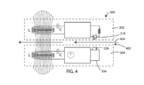
次に図4を参照すると、本明細書における様々な実施形態によるフィルタシステム300の一部分の概略図が示される。この実施形態では、フィルタ筐体304は、フィルタシステム300が動作中に流体がこの中を流れる(404)流体流路402を画定する。流体流路402は発光器318と光検出器338との間を通り得る。このようにして、流体流路402を通る流体に関する態様が、光検出器338により受信される信号を評価することにより確定され得る。光学的に判断され得る流体の態様は濁度、色、吸収度などを含み得る。しかし光検出器以外の検出器も使用され得るということが理解されるようになる。一例として、発光器318及び光検出器338の代わりに、第1の電極及び第2の電極が使用される可能性がある。さらに他の実施形態では、発光器318及び光検出器338の代わりに、音発射器又は振動発射器及び振動検出器が使用される可能性がある。多くのタイプの発射器及び検出器が企図される。
4, a schematic diagram of a portion of a
ここで図5を参照すると、本明細書における様々な実施形態によるその中に設置された一次フィルタエレメント520を有するフィルタシステム500の概略断面図が示される。フィルタシステム500は、流体入口510及び流体出口512を含むと共に内容積514を画定する筐体502を含み得る。一次フィルタエレメント520は、筐体502の内容積514内に配置され得、その中に着脱可能に配置されるように構成され得る。図5に示す図では、一次フィルタエレメント520は、一次フィルタエレメント520が内容積514の遠端部528に近い又はそれに接触する位置に在るように筐体502内へ十分挿入される。内容積514の反対側には、内容積514の近端部530が在る。内容積514の近端部530は、筐体の近端部をそれを通る流体の流れから密閉するために近端部530と隣接して嵌合する着脱可能カバー504と係合するように構成される。着脱可能カバー504は、近端部530と係合し得、ねじ、摩擦嵌合機構、掛け金、バックル、スナップ式機構などを含む様々なデバイス又は構造を介しそれへ取り付けられた状態のままであり得る。
5, a schematic cross-sectional view of a
受電及び信号伝達エレメント522がフィルタエレメント520に関連付けられ得る。受電及び信号伝達エレメント522は、上記図3を参照して説明したフィルタエレメント302に関連付けられた特徴を含み得る。送電及び信号受信エレメント524は筐体502内に又はその上に配置され得る。送電及び信号受信エレメント524は、上記図3を参照して説明したフィルタ筐体304に関連付けられた特徴を含み得る。送電及び信号受信エレメント524は、電力を受電及び信号伝達エレメント522へ無線で送信しそしてそれから戻る信号を無線で受信するように構成され得る。
The power receiving and signal transmitting
フィルタエレメントの他の部品とフィルタ筐体とに対する受電及び信号伝達エレメント522並びに送電及び信号受信エレメント524の位置は変化し得る。図5の例では、受電及び信号伝達エレメント522並びに送電及び信号受信エレメント524は互いに直隣に位置決めされる。しかし、図6を参照すると、受電及び信号伝達エレメント522並びに送電及び信号受信エレメント524は流体流路602を挟んで互いに分離される。
The location of the power receiving and
加えて、図6は、2つ以上の受電及び信号伝達エレメント522並びに2つ以上の送電及び信号受信エレメント524を示す。この例では、第2の受電及び信号伝達エレメント622並びに第2の送電及び信号受信エレメント624が示される。第2の受電及び信号伝達エレメント622並びに第2の送電及び信号受信エレメント624は流体流路602を挟んで互いに分離されるが、この場合、これらは、他の受電及び信号伝達エレメント522並びに送電及び信号受信エレメント524より流体入口510から遠く離れて配置される。
6 also shows two or more power receiving and
2つ以上の送電及び信号受信エレメント524及び/又は2つ以上の受電及び信号伝達エレメント522が存在するいくつかのケースでは、これらのいくつかの部品(図3に示すものなど)は共有され得る。例えば、いくつかの実施形態では、第1の受電及び信号伝達エレメント522は、電力を無線で受信し、次に、受信された電力を、フィルタエレメントを通る有線接続を介し第2の受電及び信号伝達エレメント622と共有するためにアンテナなどのハードウェアを含み得る。
In some cases where there are more than one power transmitting and signal receiving
本明細書におけるフィルタシステムの実施形態は2つ以上のフィルタエレメントを含み得るということが理解されることになる。例えば、本明細書におけるいくつかの実施形態では、フィルタシステムは一次フィルタエレメント及び二次フィルタエレメントを含むように構成され得る。一次フィルタエレメントは、濾過活動のほとんど又はすべてを通常動作中に行い得る。しかし、一次フィルタが故障すれば、二次フィルタエレメント(又はバックアップフィルタエレメント)が、流体を一定期間の間濾過することにより、フィルタシステムが配置される機械を保護し得る。いくつかの実施形態では、一次及び二次フィルタは同じ頻度で取り替えられる。しかし、他の実施形態では、一次フィルタは二次フィルタを変更する頻度より高い頻度で取り替えられる。 It will be understood that embodiments of the filter systems herein may include more than one filter element. For example, in some embodiments herein, the filter system may be configured to include a primary filter element and a secondary filter element. The primary filter element may perform most or all of the filtering activity during normal operation. However, if the primary filter fails, the secondary filter element (or backup filter element) may protect the machine in which the filter system is located by filtering the fluid for a period of time. In some embodiments, the primary and secondary filters are replaced at the same frequency. However, in other embodiments, the primary filter is replaced more frequently than the secondary filter is changed.
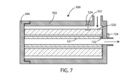
ここで図7を参照すると、本明細書における様々な実施形態によるその中に設置された一次フィルタエレメント520及び二次フィルタエレメント521を有するフィルタシステム500の概略断面図が示される。フィルタシステム500は、流体入口510及び流体出口512を含むと共に内容積514を画定する筐体502を含み得る。一次フィルタエレメント520は、筐体502の内容積514内に配置され得、その中に着脱可能に配置されるように構成され得る。二次フィルタエレメント521は、筐体502の内容積514内に配置され得、又、一次フィルタエレメント520を同時に除去するしないにかかわらずその中に着脱可能に配置されるように構成され得る。
7, a schematic cross-sectional view of a
図7に示す図では、一次フィルタエレメント520及び二次フィルタエレメント521は、一次及び二次フィルタエレメント520、521が内容積514の遠端部528に近い又はそれに接触する位置に在るように筐体502内へ十分挿入される。内容積514の反対側には、内容積514の近端部530が在る。内容積514の近端部530は、筐体の近端部をそれを通る流体の流れから密閉するために近端部530と隣接して嵌合するカバー504と係合するように構成される。
In the view shown in FIG. 7, the
第1の受電及び信号伝達エレメント522は一次フィルタエレメント520に関連付けられ(例えばその上に又はその中に配置され)得、第2の受電及び信号伝達エレメント722は二次フィルタエレメント521に関連付けられ(例えばその上に又はその中に配置され)得る。第1の送電及び信号受信エレメント524は筐体502内に又はその上に配置され得、第2の送電及び信号受信エレメント724もまた筐体502内に又はその上に配置され得る。第1の送電及び信号受信エレメント524は、電力を第1の受電及び信号伝達エレメント522へ無線で送信するようにそしてそれから信号を無線で受信するように構成され得る。第2の送電及び信号受信エレメント724は電力を第2の受電及び信号伝達エレメント722へ無線で送信するようにそしてそれから信号を無線で受信するように構成され得る。
The first power receiving and signal transmitting
本明細書におけるフィルタシステムは多くの異なる形状及び構成を採り得るということが理解されることになる。ここで図8を参照すると、本明細書における様々な実施形態によるその中に設置された一次フィルタエレメント820及び二次フィルタエレメント821を有するフィルタシステム800の概略断面図が示される。フィルタシステム800は流体入口810及び流体出口812を含む筐体802を含み得る。筐体は内容積814を画定し得る。一次フィルタエレメント820は、筐体802の内容積814内に配置され得、その中に着脱可能に配置されるように構成され得る。二次フィルタエレメント821は、筐体802の内容積814内に配置され得、また、その中に着脱可能に配置されるように構成され得る。この実施形態では、一次フィルタエレメント820は二次フィルタエレメント821を除去するしないにかかわらず除去され得る。
It will be understood that the filter systems herein may take many different shapes and configurations. Referring now to FIG. 8, a schematic cross-sectional view of a
内容積814の反対側に在るのは、内容積814の近端部830である。内容積814の近端部830は、その中の流体の流れから筐体の近端部を密封するために近端部830と隣接して嵌合するカバー804と結合するように構成される。
Opposite the
第1の受電及び信号伝達エレメント522は一次フィルタエレメント820に関連付けられ(例えばその上に又はその中に配置され)得、第2の受電及び信号伝達エレメント722は第2のフィルタエレメント821に関連付けられ(例えばその上に又はその中に配置され)得る。第1の送電及び信号受信エレメント524は筐体802内に又はその上に配置され得、第2の送電及び信号受信エレメント724も筐体802内に又はその上に配置され得る。第1の送電及び信号受信エレメント524は電力を第1の受電及び信号伝達エレメント522へ無線で送信するようにそしてそれから信号を受信するように構成され得る。第2の送電及び信号受信エレメント724は電力を第2の受電及び信号伝達エレメント722へ無線で送信するようにそしてそれから信号を無線で受信するように構成され得る。
The first power receiving and signal transmitting
上記を参照すると、フィルタシステムの多くの異なる形状及び構成が本明細書において企図される。ここで図9を参照すると、筐体912及び着脱可能且つ交換可能一次フィルタエレメント914を含むフィルタシステム910の分解斜視図が示される。示された例では、筐体912は筐体本体916と着脱可能サービス用カバー918とを含む。カバー918は、サービスのための筐体本体916の内部へのサービスアクセスを提供する。図9に描写する一般型のフィルタシステム910に関して、サービスは通常、改装又は交換のいずれかのために少なくとも1つのフィルタエレメント(描写されたフィルタエレメント914など)を筐体912から取り外し除去することに関わる。
With reference to the above, many different shapes and configurations of filter systems are contemplated herein. Now referring to FIG. 9, an exploded perspective view of a
描写された筐体912は、端921、空気入口922、及び空気出口924を有する外壁920を含む。描写された実施形態に関し、入口922及び出口924は両方とも筐体本体916内に在る。他の実施形態では、入口922又は出口924の少なくとも一方はカバー918の一部分であり得る。典型的使用では、周囲又は未濾過空気が入口922を通ってフィルタシステム910に入る。フィルタシステム910内では、この空気は所望レベルの粒子除去を得るためにフィルタエレメント914を通過される。次に、この濾過された空気は、出口924を通ってフィルタシステム910から外方向に通過し、適切な導管作業又は導管により関連エンジン又はコンプレッサ又は他のシステムの吸気の入口へ向けられる。
The depicted
図9は粒子除去のためのフィルタエレメントを説明するが、本明細書における実施形態がまた気相及び/又は液相汚染物質の除去のためのフィルタシステム及び/又はフィルタエレメントを含むということが理解されることになる。 While FIG. 9 illustrates a filter element for particulate removal, it will be understood that embodiments herein also include filter systems and/or filter elements for the removal of gas phase and/or liquid phase contaminants.
描写された特定フィルタシステム910は樽形状又は概して円筒状構成を画定する外壁920を有する。この特定構成では、出口924は通常、フィルタエレメント914により規定された長手方向中心軸の方向に延びそれを囲むので軸方向出口として説明され得る。サービス用カバー918は通常、筐体本体916の開放端926にぴったり嵌る。示された特定配置では、カバー918は、掛け金928により端926の上に適所に固定される。
The
図9はまた、フィルタエレメント914の第1のエンドキャップ954上に配置された受信アンテナ908(無線受電器の一部分であり得る)及び信号発射器962(フィードバックチャンネル回路の一部分であり得る)を示す。発射アンテナ964は筐体912の端部921上に又はその中に取り付けられ得る。いくつかの実施形態では、発射アンテナ964は無線電力発射器の一部分であり得、システムコントローラ965と電気的に連通し得る。信号受信器(この図に示さない)は、筐体912に関連付けられ得、信号発射器962から信号を受信し得る。システムコントローラ965は、データのテレメトリ、格納及び/又は処理、電力貯蔵及び/又は変調などのための様々な回路系(RAM/ROMを及び/又はデータレジスタを含む)を含み得る。いくつかの実施形態では、システムコントローラ965はマイクロプロセッサ、マイクロコントローラ、特定用途向け集積回路(ASIC)などを含み得る。
FIG. 9 also shows a receiving antenna 908 (which may be part of a wireless power receiver) and a signal emitter 962 (which may be part of a feedback channel circuit) disposed on a
本明細書で使用される、用語「フィルタエレメント」又は「エレメント」は、流体が入口922から内部を通って出口924へ導かれると濾過される流体が通過するフィルタ媒体を含む着脱可能且つ交換可能な部品を指す。フィルタエレメント914は濾過機能を行う。別途明記しない限り、用語「エレメント」、「フィルタエレメント」、及び「フィルタ」はフィルタシステム910内の着脱可能且つ交換可能な部品を指すように意図される。好適には、フィルタエレメントは、適切なサービス間隔で手動で除去及び交換され得るように構成される。
As used herein, the term "filter element" or "element" refers to a removable and replaceable part that includes a filter medium through which fluid to be filtered passes as the fluid is directed from an
本明細書では、用語「一次エレメント」又は「一次フィルタエレメント」は通常、塵、粒子又は他の汚染物質負荷の大部分がフィルタシステム使用中に発生するフィルタエレメントを指す。2つのエレメントを有する典型的システムでは、一次エレメントは、典型的組み立て中は安全エレメントの上流側に位置する。この文脈における「上流」により意味するのは「使用中のフィルタエレメント位置、フィルタシステム構成、及びシールの位置に起因して、空気又は別の流体が通常、空気又は他の流体が入口922から出口924へ移動する際に空気又は他の流体が安全エレメントを通過する前に一次エレメントを通過しなければならない」ということである。
As used herein, the term "primary element" or "primary filter element" generally refers to the filter element where the majority of the dust, particle, or other contaminant load is generated during use of the filter system. In a typical system having two elements, the primary element is located upstream of the safety element during typical assembly. By "upstream" in this context, we mean that "due to the filter element location during use, the filter system configuration, and the location of the seals, air or other fluid must typically pass through the primary element before passing through the safety element as the air or other fluid travels from the
本明細書では、用語「二次エレメント」又は「安全エレメント」は一次エレメントの下流側エレメントを指す。通常、極僅かの塵、粒子又は他の汚染物質負荷が安全エレメントに対し発生する。極僅かの塵、粒子又は他の汚染物質負荷は通常、一次エレメントの一部分の故障又はシールの故障、又は一次エレメントのサービス中の不慮の塵移動、又はいくつかの他の災難のいずれかの結果としてだけ発生する。 As used herein, the term "secondary element" or "safety element" refers to an element downstream of a primary element. Typically, negligible dust, particle or other contaminant loading occurs on the safety element. Negligible dust, particle or other contaminant loading typically occurs only as a result of either a failure of a portion of the primary element or a failure of a seal, or accidental dust migration during service of the primary element, or some other mishap.
本明細書においてこれまで示されたフィルタエレメント及び筐体の多くは、円筒形状フィルタエレメントとこれらを嵌め込むように構成された筐体とを描写するが、多くの異なる形状を有するフィルタエレメントが本明細書において企図されるということが理解されることになる。加えて、二次又は安全フィルタエレメントを含む上に参照された実施形態は一次フィルタエレメント内にちょうど収まるこのような二次又は安全フィルタエレメントを示すが、一次及び二次フィルタエレメントを含む他の多くの構成のフィルタシステムが本明細書において企図される。「第1のフィルタエレメント」への参照は、本明細書で述べた一次フィルタエレメント又は二次フィルタエレメントのいずれかを文脈に依存して指し得る。同様に、「第2のフィルタエレメント」への参照は、本明細書で述べた一次フィルタエレメント又は二次フィルタエレメントのいずれかを文脈に依存して指し得る。 While many of the filter elements and housings shown thus far herein depict cylindrically shaped filter elements and housings configured to fit within them, it will be understood that filter elements having many different shapes are contemplated herein. Additionally, while the above referenced embodiments including a secondary or safety filter element show such a secondary or safety filter element fitting within a primary filter element, many other configurations of filter systems including primary and secondary filter elements are contemplated herein. References to a "first filter element" may refer to either the primary or secondary filter element described herein, depending on the context. Similarly, references to a "second filter element" may refer to either the primary or secondary filter element described herein, depending on the context.
ここで図10を参照すると、フィルタエレメント1000を有するフィルタシステム1060の概略分解透視図が描写される。フィルタシステム1060は筐体部1062、1063を有する筐体1061を含み得る。筐体部1062、1063間には、設置中に、軸方向筐体シール装置1002が配置され、締めつけられるだろう。筐体部の一方1063は通常、フィルタエレメント収容器となり、収容溝1065をその中に含むことになる。設置中に、シール装置1002は収容溝1065へ嵌められる。第2の筐体部1063は通常、設置中に表面へ圧力を印加するように配向された圧力フランジ1064を含むだろう。圧力フランジ1064は、密閉のためにシール部材1012を溝1065の棚面部分又はシール面部分に対して適切に締めつけるためにシール面が加圧されるということを保証するのを助ける。ボルト又はオーバセンタ(over center)掛け金などの様々な保持機構が力を印加し保持するために使用され得る。
10, a schematic exploded perspective view of a
図10を依然として参照すると、筐体部1063は、設置中にシール装置1002を取り囲み、それから任意選択的ハンドル部材1030、1031と同じ方向に突出し得るシール領域外周リム1070を含む。フィルタエレメント1000はリム1070内に凹設され得る。
Still referring to FIG. 10, the
図10を依然として参照すると、筐体部1063はまた、リム1070により取り囲まれたシール領域内周リム1071であってシール係合面を含む溝1072によりリム1070から離間されたシール領域内周リム1071を含む。リム1071は任意選択的であるが、リム1071は好ましい。リム1071は通常、フィルタエレメント1000が適切に設置されると、シール装置又は部材1012の一部分がリム1071とリム1070との間に位置するように配置されることになる。
Still referring to FIG. 10, the
無線受電器の一部分であり得る受信アンテナ1092及びフィードバックチャンネル回路の一部分であり得る信号発射器1093はフィルタエレメント1000に関連付けられ(例えばその上に又はその中に配置され)得る。特に、受信アンテナ1092はフィルタエレメント1000の側壁1003上に若しくはその中に又はフィルタエレメント1000の別の部品上に又はその中に配置され得る。発射アンテナ1094は筐体1061上に又はその中に取り付けられ得る。発射アンテナ1094は無線電力発射器の一部分であり得る。信号受信器1097は、筐体1061に関連付けられ得、信号発射器1093から信号を受信し得る。
A receiving
いくつかの実施形態では、発射アンテナ1094は、電気的コンタクト1096を含むコンタクトパッド1095と電気的に連通し得る。コンタクトパッド1095は、発射アンテナ1094と他の機器とを接続して電力を運ぶことを容易にし得る。
In some embodiments, the emitting
図10の筐体1062は概略であるということに注意すべきである。筐体はまた、その設置、気流入口、気流出口などに関係する追加特徴を有し得る。また、受信アンテナ1092及び信号発射器1093は、多くの異なる特定位置に(例えば、フィルタエレメント1000の内部上に、又はフィルタエレメント1000若しくはフィルタシステムの他の部品内に若しくはその間に)在り得る。
It should be noted that the
ここで図11を参照すると、フィルタヘッド1144及びスピンオンキャニスタフィルタ1146を含むフィルタアセンブリ1140の分解斜視図が示される。フィルタヘッド1144はスピンオンキャニスタフィルタ1146とボウルカートリッジフィルタ(図示せず)との両方を動作可能に収容することができる。「動作可能に収容する」により意味するのは「フィルタヘッド1144は、浄化されるべき流体が適切なチャネルを介し導かれて目的どおり流体を浄化するようにスピンオンキャニスタフィルタ1146と係合するのに適切な構造を含む」ということである。図11を参照すると、スピンオンキャニスタフィルタ1146は使い捨て筐体1150及びバッフル板1152を含む。筐体1150は交換不能カートリッジフィルタ(フィルタエレメント)を恒久的に保持するフィルタ内部を画定する。いくつかの実施形態では、フィルタヘッド1144は端面1145を含む。
11, an exploded perspective view of a
バッフル板1152は、フィルタヘッド1144からスピンオンキャニスタフィルタ1146の内容積内への流体流れを許容するための複数の開口1142を含む。
The
フィルタヘッド1144は、内容積を取り囲む外側管を形成する連続的外壁部材1160を含むブロック1158を含む。フィルタヘッドブロック1158は、前方流システムでは入口である第1のポート、前方流システムでは出口ポートである第2のポート、及び内容積内に在り外側管により囲まれる内部又は中心管を画定し得る。
The filter head 1144 includes a
いくつかの実施形態では、外面1172は第1の機械的接続構造1174を有し得る。第1の機械的接続構造1174は多くのタイプの配置を含む。それらの可能な配置のうちの中でも、一例は、ねじ、バイオネット接続、ビード及び溝接続などを含む。示された特定の実施形態では、第1の接続構造1174は第1の複数のネジ山1176を含む。この特定の実施形態では、第1の複数のネジ山1176は壁部材1160の外面1172上に配置される。しかし、他の実施形態では、第1の複数のねじ山は壁部材1160の内面に沿って配置され得る。
In some embodiments, the
スピンオンキャニスタフィルタ1146は第2の機械的接続構造1125(この場合、ネジ山1126として描写される)を含み得る。ネジ山1126は第1の接続構造1174の第1の複数のネジ山1176と係合する。
The spin-on
無線受電器、制御回路及びフィードバックチャンネル回路(この図に示さず)はスピンオンキャニスタフィルタ1146に関連付けられ(例えばその上に又はその中に配置され)得る。無線電力発射器及び信号受信器はフィルタヘッド1144又はその部品(例えば壁部材1160)に関連付けられ(例えばその上に又はその中に配置され)得る。無線受電器及び/又はフィードバックチャンネル回路は単独使用筐体1150若しくはその一部分内に又はその上に関連付けられ得る及び/又は配置され得る。例えば、いくつかの実施形態では、無線受電器及び/又はフィードバックチャンネル回路は、単独使用筐体1150に関連付けられたドレイン及び/又は燃料中水(water-in-fuel)センサ内に又はその上に関連付けられ得る及び/又は配置され得る。
The wireless receiver, control circuitry and feedback channel circuitry (not shown in this figure) may be associated with (e.g., disposed on or within) the spin-on
態様は様々な特定且つ好ましい実施形態及び技術を参照して表現された。しかし、多くの変形及び修正が本明細書における精神及び範囲内に留まる一方でなされ得るということを理解すべきである。従って、本明細書で説明された実施形態は、網羅的であるように、又は本発明を以下の詳細説明に記載される正確な形式へ制限するように意図されていない。むしろ、実施形態は、当業者が本原理及び実施を認識及び理解し得るように選択され説明された。 The aspects have been described with reference to various specific and preferred embodiments and techniques. However, it should be understood that many variations and modifications can be made while remaining within the spirit and scope of the present disclosure. Thus, the embodiments described herein are not intended to be exhaustive or to limit the invention to the precise forms described in the following detailed description. Rather, the embodiments have been chosen and described so that others skilled in the art can appreciate and understand the present principles and implementations.
本明細書と添付特許請求の範囲において使用されるように、単数形式の冠詞と不定冠詞は、その内容が明記しない限り、複数の参照物を含むということに留意されたい。従って、例えば、「化合物」を含む組成への参照は2つ以上の化合物の混合物を含む。用語「又は」は通常、その内容が別途明確に規定しない限り「及び/又は」を含む意味で使用されるということにも留意すべきである。 It should be noted that, as used in this specification and the appended claims, singular and indefinite articles include plural references unless the content clearly dictates otherwise. Thus, for example, a reference to a composition containing "a compound" includes a mixture of two or more compounds. It should also be noted that the term "or" is typically used in its sense to include "and/or" unless the content clearly dictates otherwise.
本明細書及び添付の特許請求の範囲において使用されるように、語句「構成される」は、特定タスクを行う又は特定構成を採用するように構築又は構成されるシステム、装置又は他の構造を記述するということにも注意すべきである。語句「構成される」は、配置され構成された、構築され配置された、構築された、製造され配置されたなどの他の同様な語句と交換可能に使用され得る。 It should also be noted that, as used herein and in the appended claims, the phrase "configured" describes a system, apparatus, or other structure that is constructed or configured to perform a particular task or adopt a particular configuration. The phrase "configured" may be used interchangeably with other similar phrases, such as arranged and configured, constructed and arranged, constructed, manufactured and arranged, etc.
本明細書内のすべての刊行物及び特許出願は本発明が関係する当業者のレベルを示す。すべての刊行物及び特許出願は、各刊行物又は特許出願が参照により具体的且つ個々に示されたと同程度に、参照により本明細書に援用される。
All publications and patent applications in this specification are indicative of the level of skill of those skilled in the art to which this invention pertains. All publications and patent applications are herein incorporated by reference to the same extent as if each individual publication or patent application was specifically and individually indicated by reference.
Claims (9)
フィルタエレメント;
前記フィルタエレメント上に又はその中に配置される無線受電器;
前記無線受電器と電気的に連通する制御回路;
前記制御回路と連通するフィードバックチャンネル回路;
内容積を画定するフィルタ筐体であって、前記フィルタエレメントは前記フィルタ筐体の前記内容積内に収まるように構成される、フィルタ筐体;
前記流体フィルタシステム上に又はその中に配置される無線電力発射器;
前記流体フィルタシステム上に又はその中に配置される信号受信器;を、含み、
前記フィードバックチャンネル回路は前記フィルタエレメントを通る流体の少なくとも1つの特性を評価するために使用されるように構成される、流体フィルタシステム。 1. A fluid filter system for a vehicle, comprising:
Filter element;
a wireless receiver disposed on or within the filter element;
a control circuit in electrical communication with the wireless power receiver;
a feedback channel circuit in communication with the control circuit;
a filter housing defining an interior volume, the filter element configured to fit within the interior volume of the filter housing;
a wireless power emitter disposed on or within the fluid filter system;
a signal receiver disposed on or within the fluid filter system;
The fluid filter system, wherein the feedback channel circuit is configured to be used to evaluate at least one characteristic of a fluid passing through the filter element.
Applications Claiming Priority (4)
| Application Number | Priority Date | Filing Date | Title |
|---|---|---|---|
| US201862627425P | 2018-02-07 | 2018-02-07 | |
| US62/627,425 | 2018-02-07 | ||
| PCT/US2019/017059 WO2019157187A1 (en) | 2018-02-07 | 2019-02-07 | Filtration systems, filter elements and methods with wireless power transmission and separate signal output |
| JP2020538587A JP7291147B2 (en) | 2018-02-07 | 2019-02-07 | Filter system, filter element and method with wireless transmission and individual signal output |
Related Parent Applications (1)
| Application Number | Title | Priority Date | Filing Date |
|---|---|---|---|
| JP2020538587A Division JP7291147B2 (en) | 2018-02-07 | 2019-02-07 | Filter system, filter element and method with wireless transmission and individual signal output |
Publications (2)
| Publication Number | Publication Date |
|---|---|
| JP2023123482A JP2023123482A (en) | 2023-09-05 |
| JP7547559B2 true JP7547559B2 (en) | 2024-09-09 |
Family
ID=65494662
Family Applications (2)
| Application Number | Title | Priority Date | Filing Date |
|---|---|---|---|
| JP2020538587A Active JP7291147B2 (en) | 2018-02-07 | 2019-02-07 | Filter system, filter element and method with wireless transmission and individual signal output |
| JP2023091802A Active JP7547559B2 (en) | 2018-02-07 | 2023-06-02 | Filter system, filter element and method with wireless power transmission and individual signal output |
Family Applications Before (1)
| Application Number | Title | Priority Date | Filing Date |
|---|---|---|---|
| JP2020538587A Active JP7291147B2 (en) | 2018-02-07 | 2019-02-07 | Filter system, filter element and method with wireless transmission and individual signal output |
Country Status (7)
| Country | Link |
|---|---|
| US (1) | US11964226B2 (en) |
| EP (1) | EP3749434B1 (en) |
| JP (2) | JP7291147B2 (en) |
| CN (2) | CN112041046B (en) |
| MX (1) | MX2020008199A (en) |
| RU (1) | RU2020128109A (en) |
| WO (1) | WO2019157187A1 (en) |
Families Citing this family (5)
| Publication number | Priority date | Publication date | Assignee | Title |
|---|---|---|---|---|
| US10427082B2 (en) | 2017-08-16 | 2019-10-01 | Donaldson Company, Inc. | Filter systems, elements and methods with short-range wireless tracking features |
| EP3749434B1 (en) | 2018-02-07 | 2023-11-08 | Donaldson Company, Inc. | Filtration systems, filter elements and methods with wireless power transmission and separate signal output |
| US11189152B2 (en) | 2019-06-05 | 2021-11-30 | Donaldson Company, Inc. | Multi-zone filtration monitoring systems and methods |
| JP2024119693A (en) * | 2023-02-22 | 2024-09-03 | ヤマシンフィルタ株式会社 | Filter Device |
| JP2024119692A (en) * | 2023-02-22 | 2024-09-03 | 国立研究開発法人産業技術総合研究所 | Filter Device |
Citations (2)
| Publication number | Priority date | Publication date | Assignee | Title |
|---|---|---|---|---|
| JP2007537870A (en) | 2004-05-20 | 2007-12-27 | ドナルドソン カンパニー,インコーポレイティド | Filter assembly having an antenna |
| WO2017209684A1 (en) | 2016-05-31 | 2017-12-07 | Blueair Ab | Method for determining utilized capacity of an air filter |
Family Cites Families (18)
| Publication number | Priority date | Publication date | Assignee | Title |
|---|---|---|---|---|
| US7012685B1 (en) * | 2001-08-06 | 2006-03-14 | Wilson David J | Clogged filter detector |
| US7638042B2 (en) * | 2002-02-15 | 2009-12-29 | 3M Innovative Properties Company | System for monitoring the performance of fluid treatment cartridges |
| CN100337714C (en) * | 2002-11-06 | 2007-09-19 | 唐纳森公司 | Filter cartridge having component for use with a sensor system, assemblies and methods |
| US20060151364A1 (en) * | 2003-11-05 | 2006-07-13 | Donaldson Company | Filter cartridge having component for use with a sensor system; assemblies; and, methods |
| CN101014398A (en) * | 2004-05-20 | 2007-08-08 | 唐纳森公司 | filter assembly with antenna |
| US7713425B2 (en) * | 2005-05-11 | 2010-05-11 | Honeywell International Inc. | Oil management system |
| JP4900677B2 (en) | 2006-07-21 | 2012-03-21 | 株式会社小松製作所 | Work machine parts monitoring device |
| WO2009033923A2 (en) * | 2007-09-12 | 2009-03-19 | Mann+Hummel Gmbh | Sensor arrangement on a filter having a self-sufficient energy supply |
| US8673137B2 (en) * | 2010-03-09 | 2014-03-18 | Cummins Filtration Ip, Inc. | Apparatus, system and method for detecting the presence of genuine serviceable product components |
| JP2012241657A (en) | 2011-05-23 | 2012-12-10 | Denso Corp | Fuel filter diagnostic system and filter cartridge |
| JP6126921B2 (en) | 2013-07-04 | 2017-05-10 | 和興フィルタテクノロジー株式会社 | Liquid filter device, filter element and filter cartridge |
| DE102013214629A1 (en) * | 2013-07-26 | 2015-01-29 | Robert Bosch Gmbh | Filter device with a signaling device and a signal transfer |
| WO2017030809A1 (en) * | 2015-08-14 | 2017-02-23 | 3M Innovative Properties Company | Electromagnetic sensor for active monitoring of filter media within a filtration system |
| GB2542586A (en) | 2015-09-23 | 2017-03-29 | Rosanio William | Fluid method and system |
| US10286343B2 (en) * | 2016-10-28 | 2019-05-14 | Pall Corporation | Filter including RFID tag |
| JP6892271B2 (en) * | 2017-01-31 | 2021-06-23 | 株式会社東海理化電機製作所 | Propagation distance estimator |
| AU2018204751B2 (en) | 2017-06-30 | 2020-01-16 | The Sy-Klone Company, Llc | Air quality monitoring and control system |
| EP3749434B1 (en) | 2018-02-07 | 2023-11-08 | Donaldson Company, Inc. | Filtration systems, filter elements and methods with wireless power transmission and separate signal output |
-
2019
- 2019-02-07 EP EP19706222.7A patent/EP3749434B1/en active Active
- 2019-02-07 CN CN201980011969.XA patent/CN112041046B/en active Active
- 2019-02-07 JP JP2020538587A patent/JP7291147B2/en active Active
- 2019-02-07 US US16/968,090 patent/US11964226B2/en active Active
- 2019-02-07 RU RU2020128109A patent/RU2020128109A/en unknown
- 2019-02-07 WO PCT/US2019/017059 patent/WO2019157187A1/en not_active Ceased
- 2019-02-07 CN CN202310531687.0A patent/CN116771560B/en active Active
- 2019-02-07 MX MX2020008199A patent/MX2020008199A/en unknown
-
2023
- 2023-06-02 JP JP2023091802A patent/JP7547559B2/en active Active
Patent Citations (2)
| Publication number | Priority date | Publication date | Assignee | Title |
|---|---|---|---|---|
| JP2007537870A (en) | 2004-05-20 | 2007-12-27 | ドナルドソン カンパニー,インコーポレイティド | Filter assembly having an antenna |
| WO2017209684A1 (en) | 2016-05-31 | 2017-12-07 | Blueair Ab | Method for determining utilized capacity of an air filter |
Also Published As
| Publication number | Publication date |
|---|---|
| US11964226B2 (en) | 2024-04-23 |
| CN112041046A (en) | 2020-12-04 |
| JP2023123482A (en) | 2023-09-05 |
| EP3749434B1 (en) | 2023-11-08 |
| WO2019157187A1 (en) | 2019-08-15 |
| MX2020008199A (en) | 2020-09-22 |
| US20210023495A1 (en) | 2021-01-28 |
| RU2020128109A (en) | 2022-03-09 |
| BR112020013402A2 (en) | 2020-12-01 |
| EP3749434A1 (en) | 2020-12-16 |
| CN112041046B (en) | 2023-06-06 |
| JP7291147B2 (en) | 2023-06-14 |
| CN116771560A (en) | 2023-09-19 |
| CN116771560B (en) | 2026-02-03 |
| JP2021512778A (en) | 2021-05-20 |
Similar Documents
| Publication | Publication Date | Title |
|---|---|---|
| JP7547559B2 (en) | Filter system, filter element and method with wireless power transmission and individual signal output | |
| JP7169341B2 (en) | Filter system, filter element and method with short range radio tracking features | |
| EP2763779B1 (en) | Filter cartridge assembly | |
| US20060090431A1 (en) | Filter assembly with combination filter element | |
| JP5331241B2 (en) | Filter assembly | |
| US11266930B2 (en) | Filter element and fluid filter with radial vent hole | |
| US20190168141A1 (en) | Filter housing that accepts both single open end o-ring and double open end filter elements | |
| BR112020013402B1 (en) | FILTER ELEMENT FOR A FILTRATION SYSTEM AND FILTRATION SYSTEM | |
| US20040050767A1 (en) | Retaining ring cap filter | |
| TWM481064U (en) | Porous replaceable diesel particulate filtering apparatus | |
| MXPA06004577A (en) | Exhaust gas filter and filtering system |
Legal Events
| Date | Code | Title | Description |
|---|---|---|---|
| A521 | Request for written amendment filed |
Free format text: JAPANESE INTERMEDIATE CODE: A523 Effective date: 20230619 |
|
| A621 | Written request for application examination |
Free format text: JAPANESE INTERMEDIATE CODE: A621 Effective date: 20230619 |
|
| A131 | Notification of reasons for refusal |
Free format text: JAPANESE INTERMEDIATE CODE: A131 Effective date: 20240527 |
|
| A521 | Request for written amendment filed |
Free format text: JAPANESE INTERMEDIATE CODE: A523 Effective date: 20240703 |
|
| TRDD | Decision of grant or rejection written | ||
| A01 | Written decision to grant a patent or to grant a registration (utility model) |
Free format text: JAPANESE INTERMEDIATE CODE: A01 Effective date: 20240802 |
|
| A61 | First payment of annual fees (during grant procedure) |
Free format text: JAPANESE INTERMEDIATE CODE: A61 Effective date: 20240828 |
|
| R150 | Certificate of patent or registration of utility model |
Ref document number: 7547559 Country of ref document: JP Free format text: JAPANESE INTERMEDIATE CODE: R150 |