JP7541869B2 - Image forming device - Google Patents
Image forming device Download PDFInfo
- Publication number
- JP7541869B2 JP7541869B2 JP2020136209A JP2020136209A JP7541869B2 JP 7541869 B2 JP7541869 B2 JP 7541869B2 JP 2020136209 A JP2020136209 A JP 2020136209A JP 2020136209 A JP2020136209 A JP 2020136209A JP 7541869 B2 JP7541869 B2 JP 7541869B2
- Authority
- JP
- Japan
- Prior art keywords
- cartridge
- support portion
- image forming
- side plate
- mounting
- Prior art date
- Legal status (The legal status is an assumption and is not a legal conclusion. Google has not performed a legal analysis and makes no representation as to the accuracy of the status listed.)
- Active
Links
- 239000002184 metal Substances 0.000 claims description 13
- 230000005540 biological transmission Effects 0.000 claims description 12
- 238000011144 upstream manufacturing Methods 0.000 claims description 9
- 238000000034 method Methods 0.000 description 147
- 230000008569 process Effects 0.000 description 147
- 238000003825 pressing Methods 0.000 description 57
- 238000012546 transfer Methods 0.000 description 31
- 238000011161 development Methods 0.000 description 24
- 238000005452 bending Methods 0.000 description 11
- 230000008878 coupling Effects 0.000 description 10
- 238000010168 coupling process Methods 0.000 description 10
- 238000005859 coupling reaction Methods 0.000 description 10
- 230000015572 biosynthetic process Effects 0.000 description 9
- 238000003780 insertion Methods 0.000 description 9
- 230000037431 insertion Effects 0.000 description 9
- 238000000926 separation method Methods 0.000 description 7
- 238000010586 diagram Methods 0.000 description 6
- 230000007246 mechanism Effects 0.000 description 6
- 239000000463 material Substances 0.000 description 4
- 239000007769 metal material Substances 0.000 description 4
- 238000006243 chemical reaction Methods 0.000 description 2
- 238000004140 cleaning Methods 0.000 description 2
- 238000009434 installation Methods 0.000 description 2
- 230000001105 regulatory effect Effects 0.000 description 2
- 239000011347 resin Substances 0.000 description 2
- 229920005989 resin Polymers 0.000 description 2
- NIXOWILDQLNWCW-UHFFFAOYSA-N acrylic acid group Chemical group C(C=C)(=O)O NIXOWILDQLNWCW-UHFFFAOYSA-N 0.000 description 1
- 230000009471 action Effects 0.000 description 1
- 238000013459 approach Methods 0.000 description 1
- 239000003086 colorant Substances 0.000 description 1
- 238000004891 communication Methods 0.000 description 1
- 239000003989 dielectric material Substances 0.000 description 1
- 238000006073 displacement reaction Methods 0.000 description 1
- 230000005611 electricity Effects 0.000 description 1
- 238000005516 engineering process Methods 0.000 description 1
- 230000001678 irradiating effect Effects 0.000 description 1
- 230000000149 penetrating effect Effects 0.000 description 1
- 230000009467 reduction Effects 0.000 description 1
- 230000003014 reinforcing effect Effects 0.000 description 1
- 230000004044 response Effects 0.000 description 1
- 230000000284 resting effect Effects 0.000 description 1
- 230000032258 transport Effects 0.000 description 1
- 239000002699 waste material Substances 0.000 description 1
Images


Landscapes
- Electrophotography Configuration And Component (AREA)
Description
本発明は、記録材に画像を形成する画像形成装置に関する。 The present invention relates to an image forming apparatus that forms an image on a recording material.
プリンタ、複写機、複合機等の画像形成装置には、装置本体の内部と外部の間を移動する移動部材にカートリッジを取り外し可能に装着するものがある。特許文献1には、装置本体の内部と外部の間を移動する移動部材にカートリッジが取り外し可能に装着された画像形成装置が開示される。特許文献1の移動部材には、金属製の補強部材が設けられている。
Some image forming devices, such as printers, copiers, and multifunction devices, have a cartridge removably attached to a moving member that moves between the inside and outside of the device body.
本発明は、従来の技術をさらに発展させたものである。本発明は、装置本体と、カートリッジが取り外し可能に装着され、金属によって形成される側板を備えるトレイユニットと、を有し、装置本体に対してトレイユニットが移動可能に構成された画像形成装置に関する。本発明は、装置本体によってガイドされるトレイユニットのガイド溝を、省スペースで配置することを目的とする。 The present invention is a further development of conventional technology. The present invention relates to an image forming apparatus having a device main body, a tray unit to which a cartridge is removably attached and which has side plates formed of metal, and in which the tray unit is configured to be movable relative to the device main body. The present invention aims to arrange the guide grooves of the tray unit, which are guided by the device main body, in a space-saving manner.
上述の課題を解決するために、本発明の画像形成装置は、
カートリッジを用いて画像形成動作を行うように構成された画像形成装置であって、
装置本体と、
前記カートリッジが取り外し可能に装着され、前記装置本体の内部に位置する内部位置と、前記装置本体の外部に位置する外部位置との間を、前記装置本体に対して移動可能に構成されたトレイユニットであって、
前記カートリッジを支持する第1の側板であって、金属によって形成され、第1の支持部と、第1の外側部と、を含み、前記第1の支持部が第1の位置決め部を含み、前記画像形成動作を行う画像形成位置に前記カートリッジが位置決めされるように、前記第1の位置決め部が前記カートリッジと当接するように構成される、第1の側板と、
前記カートリッジを支持する第2の側板であって、金属によって形成され、第2の支持部と、第2の外側部と、を含み、前記第2の支持部が第2の位置決め部を含み、前記画像形成位置に前記カートリッジが位置決めされるように、前記第2の位置決め部が前記カートリッジと当接するように構成される、第2の側板と、を有し、
前記第1の側板と前記第2の側板の間に、前記カートリッジが装着方向に沿って装着される装着部が形成され、前記装着方向に見たとき、前記装着部に装着された前記カートリッジの長手方向において、前記第1の支持部と前記第2の支持部が、前記第1の外側部と前記第2の外側部の間に位置するトレイユニットと、
を有し、
前記トレイユニットは、前記外部位置から前記内部位置に移動するときに前記装置本体にガイドされる第1の被ガイド溝と第2の被ガイド溝と、を有し、
前記長手方向について、前記第1の被ガイド溝の少なくとも一部は、前記第1の支持部と前記第1の外側部の間に位置し、前記第2の被ガイド溝の少なくとも一部は、前記第2の支持部と前記第2の外側部の間に位置することを特徴とする。
In order to solve the above problems, an image forming apparatus according to the present invention comprises:
An image forming apparatus configured to perform an image forming operation using a cartridge,
A device body,
a tray unit to which the cartridge is removably attached and which is configured to be movable relative to the device body between an internal position located inside the device body and an external position located outside the device body,
a first side plate for supporting the cartridge, the first side plate being made of metal and including a first support portion and a first outer portion, the first support portion including a first positioning portion configured to abut against the cartridge so that the cartridge is positioned at an image forming position where the image forming operation is performed;
a second side plate for supporting the cartridge, the second side plate being formed of metal and including a second support portion and a second outer portion, the second support portion including a second positioning portion configured to abut against the cartridge so that the cartridge is positioned at the image forming position;
a tray unit in which a mounting portion into which the cartridge is mounted along a mounting direction is formed between the first side plate and the second side plate, and when viewed in the mounting direction, the first support portion and the second support portion are located between the first outer portion and the second outer portion in a longitudinal direction of the cartridge mounted in the mounting portion;
having
the tray unit has a first guided groove and a second guided groove that are guided by the device body when moving from the external position to the internal position,
In the longitudinal direction, at least a portion of the first guided groove is located between the first support portion and the first outer portion, and at least a portion of the second guided groove is located between the second support portion and the second outer portion.
本発明によれば、装置本体によってガイドされるトレイユニットのガイド溝を、省スペースで配置することができる。 According to the present invention, the guide groove of the tray unit, which is guided by the device body, can be arranged in a space-saving manner.
以下に図面を参照して、この発明を実施するための形態を、実施例に基づいて例示的に詳しく説明する。ただし、この実施の形態に記載されている構成部品の寸法、材質、形状それらの相対配置などは、発明が適用される装置の構成や各種条件により適宜変更されるべきものである。すなわち、この発明の範囲を以下の実施の形態に限定する趣旨のものではない。 The following describes in detail the embodiments of the present invention with reference to the drawings. However, the dimensions, materials, shapes, and relative positions of the components described in the embodiments should be changed as appropriate depending on the configuration and various conditions of the device to which the invention is applied. In other words, it is not intended to limit the scope of the present invention to the embodiments described below.
<<第1実施形態>>
[全体構成]
まず、第1の実施の形態に係る画像形成装置としてのプリンタ100は、電子写真方式のフルカラーレーザビームプリンタである。プリンタ100は、図1に示すように、装置本体100Aと、装置本体100Aに対して開閉可能に支持される前ドア31と、を有している。なお、プリンタ100の説明に関して、以下のように方向を規定する。すなわち、プリンタ100の前ドア31が設けられている側を前側(又は正面側)、その反対側を後側(又は背面側)とし、後側から前側に向かう方向並びに前側から後側に向かう方向を前後方向とする。
First Embodiment
[Overall configuration]
First, the
また、プリンタ100を前側から視た状態を基準として、左側(又は非駆動側)及び右側(又は駆動側)並びに上側及び下側を規定する。そして、右側から左側に向かう方向並びに左側から右側に向かう方向を左右方向とし、下側から上側に向かう方向並びに上側から下側に向かう方向を上下方向とする。
Furthermore, the left side (or non-drive side), right side (or drive side), top side, and bottom side are defined based on the state of the
プリンタ100は、図2に示すように、シートSに画像を形成する画像形成ユニット10と、シート給送部18と、定着装置23と、排出ローラ対24と、制御部200と、を有している。プリンタ100は、外部ホスト装置400から出力されてインターフェース部300を介して制御部200に入力される電気的画像信号に基づいて、シート状の記録媒体(以下、シートSとする)にフルカラー画像あるいはモノクロ画像を形成することができる。外部ホスト装置400は、例えばパーソナルコンピュータ、イメージリーダ及びファクシミリ等である。
As shown in FIG. 2, the
制御部200は、プリンタ100の電子写真画像形成プロセスを制御する制御手段であり、外部ホスト装置400と各種の電気的情報の授受をする。また各種のプロセス機器やセンサから入力される電気的情報の処理、各種のプロセス機器への指令信号の処理、所定のイニシャルシーケンス制御、所定の画像形成プロセスのシーケンス制御等を司る。
The
シート給送部18は、プリンタ100の下部に設けられ、シートSを収容するカセット19と、シートSを昇降可能に支持する中板21と、ピックアップローラ20aと、分離ローラ対20bと、を有している。カセット19は、装置本体100Aに対して前側から引き出し及び装着可能に構成されている。中板21に積載されたシートSは、ピックアップローラ20aによって給送され、分離ローラ対20bによって1枚ずつに分離される。なお、分離ローラ対20bは、トルクリミッタ方式やリタードローラ方式を適用可能であり、分離ローラ対20bの一方のローラに代えて、分離パッドを適用してもよい。
The
定着装置23は、ヒータによって加熱される定着フィルム23aと、定着フィルム23aに圧接する加圧ローラ23bと、を有し、定着フィルム23a及び加圧ローラ23bによって定着ニップQが形成されている。排出ローラ対24は、排出駆動ローラ24a及び排出駆動ローラ24aに従動回転する排出従動ローラ24bを有している。
The
画像形成ユニット10は、カートリッジトレイ40と、4つのプロセスカートリッジ(カートリッジ)PPY,PPM,PPC,PPKと、スキャナユニット11と、転写ユニット12と、クリーニングユニット26と、を有している。転写ユニット12は、駆動ローラ14と、補助ローラ15と、テンションローラ16と、中間転写ベルト13と、を有している。中間転写ベルト13は、駆動ローラ14、補助ローラ15及びテンションローラ16に張架され、誘電体から構成されると共に可撓性を有している。プリンタ100は、装置本体100Aに着脱可能なプロセスカートリッジPPY,PPM,PPC,PPKを用いて画像形成動作を行うように構成されている。
The
中間転写ベルト13の内側には、プロセスカートリッジPPY,PPM,PPC,PPKの各感光ドラムに対向する1次転写ローラ17Y,17M,17C,17Kが設けられ
ている。中間転写ベルト13を挟んで駆動ローラ14の反対側には、2次転写ローラ27が設けられている。中間転写ベルト13及び2次転写ローラ27によって、2次転写ニップT2が形成されている。
4つのプロセスカートリッジPPY,PPM,PPC,PPKは、それぞれイエロー(Y)、マゼンタ(M)、シアン(C)及びブラック(K)の4色のトナー画像を形成する。なお、4つのプロセスカートリッジPPY,PPM,PPC,PPKは、形成する画像の色(収納するトナーの色)が異なること以外は同じ構成である。そのため、4つのプロセスカートリッジPPY,PPM,PPC,PPKのいずれか一つについて構成及び画像形成プロセスを説明し、その他については説明を省略する。また、プロセスカートリッジPPY,PPM,PPC,PPKを区別する必要がないときに、プロセスカートリッジPPY,PPM,PPC,PPKを、単にプロセスカートリッジPPと呼ぶ場合もある。 The four process cartridges PPY, PPM, PPC, and PPK form toner images in four colors: yellow (Y), magenta (M), cyan (C), and black (K). The four process cartridges PPY, PPM, PPC, and PPK have the same configuration except for the color of the image they form (the color of the toner they contain). Therefore, the configuration and image forming process of one of the four process cartridges PPY, PPM, PPC, and PPK will be described, and the others will not be described. Also, when there is no need to distinguish between the process cartridges PPY, PPM, PPC, and PPK, the process cartridges PPY, PPM, PPC, and PPK may simply be called process cartridges PP.
プロセスカートリッジPPYは、図2及び図3に示すように、ドラムユニットOPと、現像ユニットDPと、が一体となってユニット化されている。ドラムユニットOPは、像担持体としての感光ドラム1を有しており、現像ユニットDPは、感光ドラム1に形成された潜像をトナー像として現像する現像ローラ3と、現像剤を収納する収納部3bと、を有している。感光ドラム1及び現像ローラ3の長手方向における駆動側(右側)には、それぞれドラムカップリング(駆動伝達部材、第1の駆動伝達部材)1c及び現像カップリング(駆動伝達部材、第2の駆動伝達部材)3cが設けられている。ドラムカップリング1c及び現像カップリング3cには、装置本体100Aの不図示の駆動源から駆動が伝達され、感光ドラム1及び現像ローラ3が回転する。
As shown in Figures 2 and 3, the process cartridge PPY is a unit formed by integrating a drum unit OP and a development unit DP. The drum unit OP has a
また、現像ローラ3の長手方向における非駆動側(左側)には、カートリッジ現像接点2が設けられている。カートリッジ現像接点2は、装置本体100Aに設けられた後述の本体現像接点38(図20(b)参照)に接触した状態で現像バイアスが印加される。感光ドラム1の長手方向における非駆動側には、感光ドラム1を接地電位に接続するためのアース部材(カートリッジ接点、カートリッジ電極)1bが設けられている。
A
図3に示すように、プロセスカートリッジPPYの長手方向について、プロセスカートリッジPPYの駆動側端部(第1の端部)には、ドラム軸受(駆動側支持部材、第1の端部支持部材)1aRが備えられる。駆動側端部の反対側の、プロセスカートリッジPPYの非駆動側端部(第2の端部)には、ドラム軸受(非駆動側支持部材、第2の端部支持部材)1aLが備えられる。ドラム軸受1aR、ドラム軸受1aLは、感光ドラム1を支持する。
As shown in FIG. 3, a drum bearing (driving side support member, first end support member) 1aR is provided at the driving side end (first end) of the process cartridge PPY in the longitudinal direction of the process cartridge PPY. A drum bearing (non-driving side support member, second end support member) 1aL is provided at the non-driving side end (second end) of the process cartridge PPY, which is opposite the driving side end. The drum bearing 1aR and drum bearing 1aL support the
なお、プロセスカートリッジPPYの長手方向は、感光ドラム1の回転軸線方向(長手方向)、現像ローラ3の回転軸線方向(長手方向)と同じである。また、以下の説明において、装置本体100Aやカートリッジトレイ40について説明する場合、プロセスカートリッジPPYの長手方向とは、後述の装着部40aに装着された状態のプロセスカートリッジPPYの長手方向を意味する。本実施形態において、この場合、プロセスカートリッジPPYの長手方向は、カートリッジトレイ40の移動方向、およびプロセスカートリッジPPの装着方向に直交する方向である。
The longitudinal direction of the process cartridge PPY is the same as the direction of the rotational axis (longitudinal direction) of the
複数のカートリッジとしてのプロセスカートリッジPPY,PPM,PPC,PPKは、カートリッジトレイ(トレイユニット、移動部材、移動ユニット)40に取り外し可能に装着される。述するように、カートリッジトレイ40は、プロセスカートリッジPPY,PPM,PPC,PPKを支持した状態で、装置本体100Aの内部に位置する内部位置と、装置本体100Aの外部に位置する外部位置との間を、装置本体100Aに対して移動可能に構成されている。本実施形態において、カートリッジトレイ40が内部位置に
位置されるとき、プロセスカートリッジPPY,PPM,PPC,PPKは画像形成位置に位置され、画像形成動作を行う。カートリッジトレイ40が外部位置に位置されるとき、プロセスカートリッジPPY,PPM,PPC,PPKは着脱位置に位置され、カートリッジトレイ40に着脱することができる。
The process cartridges PPY, PPM, PPC, and PPK as a plurality of cartridges are removably mounted on a cartridge tray (tray unit, moving member, moving unit) 40. As described above, the
プリンタ100は、装置本体100Aに取り付けられた前ドア(開閉部材)31を備える。前ドア31は、内部位置にあるカートリッジトレイ40を覆う閉じ位置と、内部位置にあるカートリッジトレイ40を露出させる開き位置との間を移動可能である。前ドア31をユーザが開くことで、カートリッジトレイ40が露出され、ユーザはカートリッジトレイ40にアクセス可能となる。そして、ユーザは、カートリッジトレイ40を前側に引き出すことで、各プロセスカートリッジPPY,PPM,PPC,PPKを着脱位置に位置させ、各プロセスカートリッジPPY,PPM,PPC,PPKを交換することができる。
The
[画像形成動作]
次に、このように構成されたプリンタ100の画像形成動作について説明する。プリンタ100の制御部200が、インターフェース部300からジョブ信号を受け取ると、装置本体100Aに設けられた不図示の現像離間機構が前後方向に移動する。現像離間機構によって現像ローラ3が感光ドラム1と当接する。
[Image Forming Operation]
Next, an image forming operation of the
なお、モノクロ画像を形成するジョブでは、プロセスカートリッジPPKの感光ドラムのみが現像ローラと当接し、フルカラー画像を形成するジョブでは、プロセスカートリッジPPY,PPM,PPC,PPKの各感光ドラムが各現像ローラに当接する。そして、各感光ドラム、各現像ローラ及び中間転写ベルト13が不図示の駆動源によって駆動される。
In a job to form a monochrome image, only the photosensitive drum of the process cartridge PPK comes into contact with the developing roller, whereas in a job to form a full-color image, the photosensitive drums of the process cartridges PPY, PPM, PPC, and PPK come into contact with their respective developing rollers. Each photosensitive drum, each developing roller, and the
スキャナユニット11は、画像信号に対応したレーザ光をプロセスカートリッジPPYの感光ドラム1上に照射する。このとき感光ドラム1は、帯電部材(帯電ローラ)5により表面が予め所定の極性・電位に一様に帯電されており、スキャナユニット11からレーザ光が照射されることによって表面に静電潜像が形成される。感光ドラム1に形成された静電潜像は、現像ローラ3により現像され、感光ドラム1上にイエロー(Y)のトナー像が形成される。
The
なお、カートリッジトレイ40には、前露光手段としてのライトガイド57(図5(b)参照)が設けられている。ライトガイド57は、例えば透明なアクリル等で成形されている。そして、帯電ローラ5による感光ドラム1の表面の帯電前に、不図示の光源から光が発せられ、この光がライトガイド57によって長手方向に均一に分散された状態で感光ドラム1の表面に照射される。これにより、感光ドラム1の表面の電位が安定化し、良好なトナー像を形成することができる。
The
同様にして、プロセスカートリッジPPM,PPC,PPKの各感光ドラムにもスキャナユニット11からレーザ光が照射され、各感光ドラムにマゼンタ(M)、シアン(C)及びブラック(K)のトナー像が形成される。各感光ドラム上に形成された各色のトナー像は、1次転写ローラ17Y,17M,17C,17Kに印加される1次転写バイアスによって中間転写ベルト13に転写される。中間転写ベルト13に転写されたフルカラーのトナー像は、駆動ローラ14によって回転する中間転写ベルト13により2次転写ニップT2まで搬送される。なお、各色の画像形成プロセスは、中間転写ベルト13上に1次転写された上流のトナー像に重ね合わせるタイミングで行われる。
Similarly, the
この画像形成プロセスに並行して、シート給送部18によって送り出されたシートSは
、レジストレーションローラ対22によって斜行が補正される。更にレジストレーションローラ対22は、中間転写ベルト13によって搬送されるトナー像に合わせてシートSを2次転写ローラ27へ向けて搬送する。シートSは、2次転写ローラ27に印加された2次転写バイアスによって、2次転写ニップT2において中間転写ベルト13上のフルカラーのトナー像が転写される。また、トナー像転写後、中間転写ベルト13の表面に残ったトナーはクリーニングユニット26によって除去され、不図示の廃トナー回収容器へと回収される。
In parallel with this image forming process, the sheet S sent out by the
トナー像が転写されたシートSは、定着装置23の定着ニップQにおいて所定の熱及び圧力が付与されて、トナーが溶融し、その後固着することで、シートSに画像が定着する。定着装置23を通過したシートSは、排出ローラ対24によって排出トレイ25に排出される。
The sheet S onto which the toner image has been transferred is subjected to a predetermined heat and pressure in the fixing nip Q of the fixing
[カートリッジトレイ]
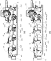
次に、カートリッジトレイ40の構成について説明する。カートリッジトレイ40は、図4(a)(b)に示すように、左右方向に間隙を空けて配置されたトレイ側板41L,41Rと、トレイ側板41L,41Rを連結する連結部材42,43,44,45,46と、ガイド部材47L,47Rと、を有している。なお、以下の説明において、左右1対に設けられる部材については、参照符号の末尾に「L」又は「R」を付記することで左右の区別を行う。
[Cartridge Tray]
Next, the configuration of the
プロセスカートリッジPPY,PPM,PPC,PPKは、トレイ側板41L,41Rによって支持される。トレイ側板(駆動側側板、第1の側板)41Rと、トレイ側板(非駆動側側板、第2の側板)41Lの間には、プロセスカートリッジPPY,PPM,PPC,PPKが装着される装着部40aが形成される。プロセスカートリッジPPYは装着部40aYに装着され、プロセスカートリッジPPMは装着部40aMに装着され、プロセスカートリッジPPCは装着部40aCに装着され、プロセスカートリッジPPKは装着部40aKに装着される。プロセスカートリッジPPY,PPM,PPC,PPKは、装着方向(矢印In方向)に沿って、装着部40aY、40aM、40aC、40aKに装着される。
The process cartridges PPY, PPM, PPC, and PPK are supported by
連結部材42,43,44,45,46は、樹脂材料からなり、前側から後側に順に並んでいる。連結部材42,43,44,45には、上述したライトガイド57がそれぞれ設けられている。トレイ側板41L,41Rは、金属材料からなる。ガイド部材(駆動側カバー部材、第1のカバー部材)47Rはトレイ側板41Rに支持され、ガイド部材(非駆動側カバー部材、第2のカバー部材)47Lはトレイ側板41Lに支持されている。ガイド部材47Rはガイド溝(第1の被ガイド溝)47aRを備え、ガイド部材47Lはガイド溝(第2の被ガイド溝)47aLを備える。ガイド溝47aL,47aRは、複数のカートリッジが並ぶ方向に沿って延びており、カートリッジトレイ40を装置本体100Aに対して引き出し方向及び挿入方向に案内する。また、ガイド溝47aL,47aRは、装置本体100Aに設けられた不図示のストッパに係合することで、カートリッジトレイ40が所定の位置よりも引き出されることを規制する。
The connecting
連結部材42は、受け部42b,42bと、把持部42dと、を有しており、把持部42dをユーザが把持して引き出すことで、カートリッジトレイ40を装置本体100Aから引き出すことができる。また、受け部42b,42bは、前ドア31が閉じられた状態でプリンタ100に前方向への衝撃がかかった際に、前ドア31に当たることでプリンタ100の内部部品の破損を防いでいる。同様にして、連結部材46は、受け部46a,46aを有しており、受け部46a,46aは、プリンタ100に後方向への衝撃がかかった際に、定着ステー35(図9参照)に当たることでプリンタ100の内部部品の破損を
防いでいる。
The connecting
トレイ側板41L,41Rは、下部に比べて上部が外側に絞られた形状をしており、トレイ側板41L,41Rとの間の左右方向における距離は、上部が広く下部が狭くなっている。これにより、プロセスカートリッジPPY,PPM,PPC,PPKの挿抜性を損なうことなく、カートリッジトレイ40の左右幅を小さくすることができ、プリンタ100の小型化に貢献している。
The
更に、トレイ側板41L,41Rは、下側がL字に折曲されており、強度を確保している。トレイ側板41L,41Rと各連結部材42,43,44,45,46は、それぞれビスで締結されているが、これに限らず、熱カシメ等を用いてもよい。また、連結部材42,46のみをトレイ側板41L,41Rに対して締結し、連結部材43,44,45はトレイ側板41L,41Rに締結しなくてもよい。
Furthermore, the
トレイ側板41Rには、図4(a)乃至図5(b)に示すように、カートリッジ係合部(第1の位置決め部)41gR,41hR,41iR,41jRが設けられており、カートリッジ係合部41gR,41hR,41iR,41jRは、それぞれ略V字状に形成されている。具体的には、カートリッジ係合部41gR,41hR,41iR,41jRは、引き出し方向に対して前側の斜面が65°、後側の斜面が45°となるように形成されている。
As shown in Figs. 4(a) to 5(b), the
トレイ側板41Lには、図4(a)に示すように、カートリッジ係合部(第2の位置決め部)41gL,41hL,41iL,41jLが設けられており、カートリッジ係合部41gL,41hL,41iL,41jLは、それぞれ略V字状に形成されている。具体的には、カートリッジ係合部41gL,41hL,41iL,41jLは、引き出し方向に対して前側の斜面が65°、後側の斜面が45°となるように形成されている。
As shown in FIG. 4(a), the
プロセスカートリッジPPY,PPM,PPC,PPKは、カートリッジトレイ40によって、画像形成動作を行う画像形成位置に位置決めされる。画像形成動作が行われる間、プロセスカートリッジPPYのドラム軸受1aR(図3(a)参照)は、カートリッジ係合部41gRに当接し、プロセスカートリッジPPYのドラム軸受1aL(図3(b)参照)は、カートリッジ係合部41gLに当接する。同様に、プロセスカートリッジPPM,PPC,PPKのドラム軸受1aRは、カートリッジ係合部41hR,41iR,41jRに当接する。また、プロセスカートリッジPPM,PPC,PPKのドラム軸受1aLは、カートリッジ係合部41hL,41iL,41jLに当接する。つまり、カートリッジ係合部41gR、カートリッジ係合部41gLは、プロセスカートリッジPPYが画像形成位置に位置決めされるように、プロセスカートリッジPPYのドラム軸受1aR、ドラム軸受1aLに当接し、これらを支持する。同様に、カートリッジ係合部41hR,41iR,41jR、カートリッジ係合部41hL,41iL,41jLは、プロセスカートリッジPPM,PPC,PPKのドラム軸受1aR、ドラム軸受1aLに当接し、これらを支持する。
The process cartridges PPY, PPM, PPC, and PPK are positioned by the
プロセスカートリッジPPY,PPM,PPC,PPKは、自重若しくは押圧ユニット33、34(第一の押圧部材34,第二の押圧部材33)で下方向に押圧されることによってカートリッジトレイ40に対して位置決めされる(図14~図20)。押圧ユニット33,34は、画像形成時において各プロセスカートリッジを下方向に押圧することで、各プロセスカートリッジ及び各プロセスカートリッジと一体のカートリッジトレイ40を装置本体100Aに位置決めする。詳しくは後述するが、押圧ユニット33,34は、プリンタ100の前ドア31の開閉動作に連動して、各プロセスカートリッジを押圧する押圧位置と、離間する離間位置とに移動可能に、装置本体100Aに組み付けられている。
The process cartridges PPY, PPM, PPC, and PPK are positioned relative to the
また、連結部材42,43,44,45には、左端部にボス部42aL,43aL,44aL,45aLがそれぞれ形成され、右端部にボス部42aR,43aR,44aR,45aRがそれぞれ形成されている。なお、各色のプロセスカートリッジには、図3(a)(b)に示すように、左右端部に溝部1dR,1dLが形成されている。そして、各プロセスカートリッジPPY,PPM,PPC,PPKの溝部1dR,1dLが、左端部側でボス部42aL,43aL,44aL,45aLに係合し、右端部側でボス部42aR,43aR,44aR,45aRに係合する。これにより、各プロセスカートリッジPPY,PPM,PPC,PPKがカートリッジトレイ40に対して回転止めされる。
The connecting
このようにして、プロセスカートリッジPPY,PPM,PPC,PPKは、カートリッジトレイ40に対して装着され、各プロセスカートリッジは、ガイド部材47Lに設けられた線材(ドラムアース)48を介して接地される。
In this way, the process cartridges PPY, PPM, PPC, and PPK are mounted on the
[カートリッジトレイの詳細]
図6(a)、図6(b)、図7(a)、図7(b)、図8を用いて、カートリッジトレイ40の詳細について説明する。
図6(a)、図6(b)は、カートリッジトレイ40の駆動側を示す側面図である。図6(a)、図6(b)は、カートリッジトレイ40をプロセスカートリッジPPYの長手方向に沿って見た図であり、図6(b)ではガイド部材47Rが描かれていない。図7(a)、図7(b)は、カートリッジトレイ40の非駆動側を示す側面図である。図7(a)、図7(b)は、カートリッジトレイ40をプロセスカートリッジPPYの長手方向に沿って見た図であり、図7(b)ではガイド部材47Lが描かれていない。図8はカートリッジトレイ40の上面図である。図8はカートリッジトレイ40をプロセスカートリッジPPY、PPM,PPC,PPKの装着方向Inに沿って見た図である。
[Cartridge Tray Details]
The
6(a) and 6(b) are side views showing the drive side of the
図6(b)に示すように、トレイ側板41Rは、カートリッジ係合部41gR,41hR,41iR,41jRを有する第1の支持部41R1と、第1の外側部41R2と、第1の支持部41R1と第1の外側部41R2を接続する第1の接続部41R3を備える。トレイ側板41Rは、金属によって形成されている。本実施形態において、トレイ側板41Rは一枚の金属板であり、第1の支持部41R1と、第1の外側部41R2と、第1の接続部41R3を一体的に備える。第1の支持部41R1と、第1の外側部41R2は、カートリッジトレイ40が装置本体100Aに対して移動する移動方向に沿って延びている。
As shown in FIG. 6(b), the
トレイ側板41Rは、金属板を絞り加工することによって形成される。その結果、第1の接続部41R3は、プロセスカートリッジPPYの長手方向に見て、水平方向で第1の支持部41R1と第1の外側部41R2の間に位置する部分と、鉛直方向で第1の支持部41R1と第1の外側部41R2の間に位置する部分を有する。さらに、トレイ側板41Rには、第1の開口41R5が備えられる。第1の開口41R5に、カートリッジ係合部41gR,41hR,41iR,41jRが形成されている。鉛直方向について、第1の開口41R5の上端は、第1の外側部41R2の下端よりも上方に位置し、第1の開口41R5の下端は、第1の支持部41R1の上端、および第1の接続部41R3よりも下方に位置する。第1の開口41R5から、プロセスカートリッジPPY,PPM,PPC,PPKが装着部40aの外部に露出される。より具体的には、第1の開口41R5から、プロセスカートリッジPPY,PPM,PPC,PPKのドラムカップリング1cが、カートリッジトレイ40の外部に露出される。
The
図6(a)に示すように、カートリッジトレイ40は、装着部40aの外側でトレイ側板41Rに取付けられる、ガイド部材(第1のカバー部材)47Rを有する。ガイド部材
47Rは、第1の支持部41R1を覆っている。より具体的には、ガイド部材47Rは、プロセスカートリッジPPYの長手方向に見たときに、カートリッジ係合部41gR,41hR,41iR,41jRが露出されるように、第1の支持部41R1を覆っている。
As shown in Fig. 6A, the
また、上述のように、ガイド部材47Rは、ガイド溝(第1の被ガイド溝)47aRを備える。プロセスカートリッジPPY,PPM、PPC、PPKの装着方向Inについて、ガイド溝47aRは、カートリッジ係合部41gR,41hR,41iR,41jRの下流側に位置する。ガイド溝47aRは、プロセスカートリッジPPY,PPM,PPC,PPKが並ぶ方向に沿って延びている。これにより、カートリッジトレイ40は、プロセスカートリッジPPY,PPM,PPC,PPKが並ぶ方向に沿って、装置本体100Aに対して移動可能とされる。
As described above, the
図7(b)に示すように、トレイ側板41Lは、カートリッジ係合部41gL,41hL,41iL,41jLを有する第2の支持部41L1と、第2の外側部41L2と、第2の支持部41L1と第2の外側部41L2を接続する第2の接続部41L3を備える。トレイ側板41Lは、金属によって形成されている。本実施形態において、トレイ側板41Lは一枚の金属板であり、第2の支持部41L1と、第2の外側部41L2と、第2の接続部41L3を一体的に備える。第2の支持部41L1と、第2の外側部41L2は、カートリッジトレイ40が装置本体100Aに対して移動する移動方向に沿って延びている。
As shown in FIG. 7(b), the
トレイ側板41Lは、金属板を絞り加工することによって形成される。その結果、第2の接続部41L3は、プロセスカートリッジPPYの長手方向に見て、水平方向で第2の支持部41L1と第2の外側部41L2の間に位置する部分と、鉛直方向で第2の支持部41L1と第2の外側部41L2の間に位置する部分を有する。さらに、トレイ側板41Lには、第2の開口(接点開口)41L5が備えられる。第2の開口41L5に、カートリッジ係合部41gL,41hL,41iL,41jLが形成されている。鉛直方向について、第2の開口41L5の上端は、第2の外側部41L2の下端よりも上方に位置し、第2の開口41L5の下端は、第2の支持部41L1の上端、および第2の接続部41L3よりも下方に位置する。第2の開口41L5から、プロセスカートリッジPPY,PPM,PPC,PPKが装着部40aの外部に露出される。より具体的には、第2の開口41L5から、プロセスカートリッジPPY,PPM,PPC,PPKのアース部材1bが、装着部40aの外部に露出される。
The
図7(a)に示すように、カートリッジトレイ40は、装着部40aの外側でトレイ側板41Lに取付けられる、ガイド部材(第2のカバー部材)47Lを有する。ガイド部材47Lは、第2の支持部41L1を覆っている。より具体的には、ガイド部材47Lは、プロセスカートリッジPPYの長手方向に見たときに、第2の開口41L5の少なくとも一部が覆われるように、第2の支持部41L1を覆っている。また、ガイド部材47Lには、線材48が備えられる。プロセスカートリッジPPYの長手方向に見て、線材48は、第2の開口41L5と重なる位置に配置される。
As shown in FIG. 7(a), the
また、上述のように、ガイド部材47Lは、ガイド溝(第2の被ガイド溝)47aLを備える。プロセスカートリッジPPY,PPM、PPC、PPKの装着方向Inについて、ガイド溝47aLは、カートリッジ係合部41gL,41hL,41iL,41jLの下流側に位置する。ガイド溝47aLは、プロセスカートリッジPPY,PPM,PPC,PPKが並ぶ方向に沿って延びている。これにより、カートリッジトレイ40は、プロセスカートリッジPPY,PPM,PPC,PPKが並ぶ方向に沿って、装置本体100Aに対して移動可能とされる。
As described above, the
図8に示すように、装着方向Inに見たとき、装着部40aに装着されたプロセスカートリッジPPの長手方向(矢印LD)において、第1の支持部41R1と第2の支持部41L1が、第1の外側部41R2と第2の外側部41L2の間に位置する。また、装着方向Inに見たとき、第1の開口41R5を介して、カートリッジ係合部41gR,41hR,41iR,41jRが、装着方向Inの上流側(紙面手前側)に露出される。同様に、第2の開口41L5を介して、カートリッジ係合部41gL,41hL,41iL,41jLが、装着方向Inの上流側(紙面手前側)に露出される。
As shown in FIG. 8, when viewed in the mounting direction In, the first support portion 41R1 and the second support portion 41L1 are located between the first outer portion 41R2 and the second outer portion 41L2 in the longitudinal direction (arrow LD) of the process cartridge PP mounted in the mounting
[カートリッジトレイの位置決め構成]
次に、カートリッジトレイ40の位置決め構成について説明する。装置本体100A(図1参照)は、図9に示すように左右1対の本体側板36L,36Rと、本体側板36L,36Rを連結すると共にプロセス領域と定着領域とを区画する定着ステー35と、を有する本体フレーム30を有している。プロセス領域は、プロセスカートリッジPPY,PPM,PPC,PPKが収容される領域であり、定着領域は、定着装置23が収容される領域である。本体側板36L,36R及び定着ステー35は、金属材料から構成されている。
[Cartridge tray positioning configuration]
Next, the positioning structure of the
本体側板36L,36Rは、装置奥側にそれぞれ軸支部50aL,50aRを有しており、これら軸支部50aL,50aRには、位置決め軸50が支持されている。なお、位置決め軸50は、軸支部50aL,50aRに対して移動不能に固定されているが、前後方向及び上下方向に移動不能であれば、回転可能に支持されていてもよい。
The main
また、本体側板36L,36Rは、装置手前側にそれぞれ位置決め溝36aL,36aRを有している。図10に示すように、カートリッジトレイ40のトレイ側板41L,41Rの手前側には、それぞれ軸支部41dL,41dRが形成されている。軸支部41dL,41dRには、位置決め軸49が支持されている。位置決め軸49は、トレイ側板41L,41Rを貫通しており、位置決め軸49の左側の端部49aと右側の端部(不図示)がトレイ側板41L,41Rの外側に突出している。なお、位置決め軸49は、軸支部41dL,41dRに対して移動不能に固定されているが、前後方向及び上下方向に移動不能であれば、回転可能に支持されていてもよい。また、位置決め軸49,50は、左右方向に延びて断面円形の丸棒状の軸から構成されるが、その形状は限定されない。
The main
そして、連結部材42には、位置決め軸49の軸方向における略中央部を下支えする軸接触部42cが形成されており、軸接触部42cは、位置決め軸49の下方向の撓みを規制する。なお、軸接触部42cは、位置決め軸49の軸方向における略中央部に限らず、位置決め軸49の他の位置を下支えしてもよいが、位置決め軸49の下方向の撓みは位置決め軸49の中央部で規制すると好適である。また、軸接触部42cを軸方向に長大に形成してもよい。
The connecting
図11(d)に示すように、本体側板36Rの位置決め溝36aRは、カートリッジトレイ40の挿入方向Y1に沿って形成されており、奥側に形成される嵌合溝37aRと、手前側に形成される案内溝37bRと、を有している。
As shown in FIG. 11(d), the positioning groove 36aR of the main
嵌合溝37aRは、位置決め軸49の外径と同じ又は僅かに小さい幅を有しており、カートリッジトレイ40が装着位置に位置する際に位置決め軸49の端部49aに嵌合する。案内溝37bRは、位置決め軸49の外径よりも大きい幅を有しており、カートリッジトレイ40を装置本体100Aに装着する際に位置決め軸49の端部49aを嵌合溝37aRに案内する。なお、案内溝及び嵌合溝は、本体側板36Lにも同様に形成されており、位置決め軸49の左側の端部を案内又は係合する。
The fitting groove 37aR has a width equal to or slightly smaller than the outer diameter of the
図5(b)に示すように、トレイ側板41L,41Rには、奥側にそれぞれ位置決め溝41bL,41bRが形成されており、位置決め溝41bL,41bRは、位置決め軸49に係合することでカートリッジトレイ40を位置決めする。図11(a)乃至図11(c)は、位置決め溝41bRを示す拡大図である。なお、位置決め溝41bL,41bRは同様の構成であるため、位置決め溝41bRのみを説明し、位置決め溝41bLの説明は省略する。
As shown in FIG. 5(b), the
図11(a)乃至図11(c)に示すように、位置決め溝41bRは、傾斜面41fと、傾斜面41fに連続して形成される位置決め面41eと、を有している。位置決め面41eは、カートリッジトレイ40の挿入方向Y1に対して略垂直な方向に延びており、位置決め軸50に突き当たることでカートリッジトレイ40を挿入方向に位置決めする。傾斜面41fは、挿入方向Y1に向かうに従って下方に傾斜している。また、カートリッジトレイ40の連結部材46には、摺動面46d(図5(b)参照)が形成されており、摺動面46dは、傾斜面41fから手前側に連続するように形成されている。
As shown in Figures 11(a) to 11(c), the positioning groove 41bR has an
図11(a)に示すように、カートリッジトレイ40が装着されている際には、カートリッジトレイ40の自重及び押圧ユニット33,34(図14(a)参照)によって下方に力がかかることで、傾斜面41fは、位置決め軸50からの反力F1を受ける。反力F1は、挿入方向Y1の分力を有しているため、カートリッジトレイ40は挿入方向Y1に引き込まれ、F2方向に移動する。これにより、位置決め面41eは位置決め軸50に対して押し当てられ、カートリッジトレイ40を装置本体100Aに対して精度良く位置決めすることができる。このように、傾斜面41fは、分力を発生させるように形成されている。
As shown in FIG. 11(a), when the
位置決め軸50は、図12に示すように、本体側板36L,36Rの軸支部50aL,50aRによって軸支されている。カートリッジトレイ40が装置本体100Aに装着されている状態では、位置決め溝41bL,41bRは軸支部50aL,50aRよりも軸方向内側に位置する。このため位置決め軸50の中央部は、カートリッジトレイ40の自重及び押圧ユニット33,34(図14(a)参照)によって下方向に力がかかり、下方向(図の白抜き矢印の方向)に撓む虞がある。
As shown in FIG. 12, the
そこで、本実施の形態では、連結部材46の軸方向(左右方向)における略中央部にリブ46bを形成している。リブ46bは、位置決め軸50の軸方向における略中央部に当接して下支えすることで、位置決め軸50の下方向の撓みを規制する。なお、リブ46bは、位置決め軸50の軸方向における略中央部に限らず、位置決め軸50の他の位置を下支えしてもよいが、位置決め軸50の下方向の撓みは位置決め軸50の中央部で規制すると好適である。また、リブ46bを軸方向に長大に形成したり、リブ46bを軸方向に複数設けたりしてもよい。また、本実施の形態では、位置決め軸50が重力方向の力を受けるために下方への撓みを規制しているが、位置決め軸50の撓み方向への力を受けて位置決め軸50の撓みを規制するのであれば、位置決め軸50の下部に接触しなくてもよい。
In this embodiment, the
また、連結部材46には、図12及び図13に示すように、定着ステー35に係止可能な係止部46c,46cが形成されている。係止部46c,46cは、定着ステー35に係止することで、連結部材46を含むカートリッジトレイ40の下方向の撓みを規制することができる。カートリッジトレイ40の下方向の撓みを抑えることで、カートリッジトレイ40の位置決め溝41bL,41bRにおける変形も抑えられ、カートリッジトレイ40を位置決め軸50に対して精度良く位置決めすることができる。なお、係止部46c,46cは、カートリッジトレイ40の装着動作を阻害することが無く、1つのみ設けられても3つ以上設けられてもよい。また、1つの係止部46cを軸方向(左右方向)に長大に形成してもよい。
Furthermore, as shown in Figs. 12 and 13, the connecting
[カートリッジトレイの引き出し及び装着動作]
次に、カートリッジトレイ40の引き出し及び装着動作について説明する。各プロセスカートリッジPPY,PPM,PPC,PPKは購入したユーザにとって満足できる品質の画像を形成することが出来なくなる程度まで現像剤が消費された際に、プロセスカートリッジとしての商品価値が喪失する。
[Cartridge tray pull-out and installation operations]
Next, a description will be given of the pulling out and mounting operations of the
そこで、例えば、個々のプロセスカートリッジの現像剤残量を検知する手段(不図示)を具備させて、制御部200において、検知残量値を、予め設定したカートリッジ寿命予告や寿命警告のための閾値と比較してもよい。そして、検知残量値が閾値よりも少ない残量値となったプロセスカートリッジについては、表示部(不図示)に、そのプロセスカートリッジについての寿命予告あるいは寿命警告を表示させ、ユーザにプロセスカートリッジの交換を促す。そしてユーザはプリンタ100の前ドア31を開け、カートリッジトレイ40を装置外まで引き出し、各プロセスカートリッジPPY,PPM,PPC,PPKを交換する。以下では、カートリッジトレイ40の引き出し及び装着動作を詳述する。
For example, a means (not shown) for detecting the amount of developer remaining in each process cartridge may be provided, and the
前ドア31は、図14(a)乃至図15(b)に示すように、装置本体100Aに対して開閉可能に支持されており、前ドア31と装置本体100Aとの間に連結されるドアリンク32L,32Rによって開状態で保持可能となっている。
As shown in Figures 14(a) to 15(b), the
ユーザによって前ドア31が開かれると、ドアリンク32L,32Rを介して不図示の複数のリンク部材が連動して、転写ユニット12が駆動ローラ14を中心に1°程度回転する。これにより、図16(c)に示すように、各プロセスカートリッジの感光ドラム1が中間転写ベルト13から離間する。
When the
次に、図20(b)に示すように、装置本体100Aの左側(非駆動側)に設けられた本体現像接点38が各現像ローラ3に電気的に接続されたカートリッジ現像接点2(図3(b)参照)から退避すると共に、押圧ユニット33,34の押圧が解除される。すなわち、第2の押圧部材としての押圧ユニット33が第2の押圧位置から第2の離間位置へ移動するとともに、第1の押圧部材としての押圧ユニット34が第1の押圧位置から第1の離間位置へ移動する。次に、各プロセスカートリッジの駆動側のドラムカップリング1c及び現像カップリング3c(図3(a))の係合が解除されると共に、図14(b)及び図16(b)に示すように、トレイ押圧ユニット51によるカートリッジトレイ40の押圧が解除される。その結果、カートリッジトレイ40を装置本体100Aの外部に取り出せる状態となる。
Next, as shown in FIG. 20(b), the main
ここで、トレイ押圧ユニット51は、本体側板36L,36Rに支持されるホルダ52L,52Rにそれぞれ設けられ、画像形成時においてカートリッジトレイ40を後側から前側に押圧している。トレイ押圧ユニット51は、図16(a)(b)に示すように、トレイ押圧レバー53と、トレイ押圧リンク54と、付勢バネ(不図示)と、を有している。
The
トレイ押圧レバー53は、図16(a)に示すように、前ドア31が閉じた状態において、付勢バネによって付勢されるトレイ押圧リンク54によって押圧されている。これにより、トレイ押圧レバー53は、カートリッジトレイ40のトレイ側板41Rに形成される被押圧部41cを後側に押圧する。
As shown in FIG. 16(a), when the
前ドア31が開かれると、図16(b)に示すように、ドアリンク32L,32R及び不図示のリンク部材によってトレイ押圧レバー53は下方に退避される。これにより、トレイ押圧レバー53によるカートリッジトレイ40の後側への押圧が解除され、カートリ
ッジトレイ40を装置本体100Aの外部に取り出し可能となる。
When the
次に、図11(a)乃至図11(f)を用いて、位置決め軸49,50の周辺の動きについて説明するが、位置決め軸49,50におけるカートリッジトレイ40の位置決め構成は左右で同一なため、装置右側のみを説明し、装置左側の説明は省略する。図11(a)乃至図11(f)に示すように、カートリッジトレイ40が引き出され始めると、傾斜面41fが位置決め軸50に摺動するため、カートリッジトレイ40の奥側が僅かに持ちあがる。そして、カートリッジトレイ40の連結部材46に設けられた摺動面46dが位置決め軸50に摺動しながら引き出し方向Y2にカートリッジトレイ40が移動する。
Next, the movement around the
同時に、カートリッジトレイ40の位置決め軸49の端部49aは、位置決め溝36aRの嵌合溝37aRから抜け出し、案内溝37bRに受け渡される。カートリッジトレイ40は、位置決め軸49の端部49aが案内溝37bRに案内されながら、引き出し方向Y2に引き出される。図11(a)(d)は、カートリッジトレイ40が装着位置に位置する状態を示す。図11(b)(e)は、カートリッジトレイ40が装着位置から3mm程度引き出された状態を示す。図11(c)(f)は、カートリッジトレイ40が装着位置から10mm程度引き出された状態を示す。
At the same time, the
ある程度までカートリッジトレイ40が引き出されると、カートリッジトレイ40は、図14(b)及び図15(b)に示すように、コロ56L,56R(第1の回転体と第2の回転体)に乗って案内される。そして、カートリッジトレイ40は、装置本体100Aの外部に引き出される。なお、画像形成時においては、カートリッジトレイ40とコロ56L,56Rは接触しておらず、0.5mm程度のクリアランスを確保している。
When the
図17は、カートリッジトレイが引き出される過程の図である。カートリッジトレイ40のガイド溝47aL、47aRは、ドアリンク32L、32Rに設けられたガイド部32aL、32aR(第1のガイド突起と第2のガイド突起)によってガイドされる。カートリッジトレイ40のガイド溝47aLは、ドアリンク32Lに設けられたガイド部32aLによってガイドされる。ガイド溝47aRとガイド部32aRの構成は、ガイド溝47aLとガイド部32aLの構成と同様である。よって、カートリッジトレイ40の引き出し量が大きな場合においても、カートリッジトレイ40傾きを低減し滑らかに引き出すことができる。またカートリッジトレイ40を引き出した際の姿勢を安定させることができるので、プロセスカートリッジの交換性を向上させることができる。
Figure 17 is a diagram showing the process of the cartridge tray being pulled out. The guide grooves 47aL, 47aR of the
ガイド溝47aL、47aRは、金属材料からなるトレイ側板41L、41Rの第1の支持部41R1、第2の支持部41L1の外側に設けられ、外側が開いたコの字形状に形成されている。ガイド溝47aL、47aRの下方には、第1の支持部41R1、第2の支持部41L1から外側に延伸した突出部41L4、41R4(第1の突出部と第2の突出部)が配されている。ガイド溝47aL、47aRは、外側部41L2、41R2と突出部41L4、41R4との間に配置される。プロセスカートリッジのカートリッジトレイ40への装着方向において、ガイド溝47aLは、カートリッジ係合部41gL,41hL,41iL,41jLの下流側に配置され、ガイド溝47aRは、カートリッジ係合部41gR,41hR,41iR,41jRの下流側に配置される。これにより、強固なガイドを構成することができる。カートリッジトレイ40が引き出される際に、突出部41L4、41R4はコロ56L,56Rに乗って支持される。
The guide grooves 47aL, 47aR are provided on the outside of the first support portion 41R1 and the second support portion 41L1 of the
また、ガイド溝47aL、47aRは、感光ドラム1の長手方向において、第1の外側部41R2、第2の外側部41L2より内側に設けられており、それらの少なくとも一部は、該長手方向において、第1の支持部41R1と第1の外側部41R2との間、第2の支持部41L1と第2の外側部41L2との間にそれぞれ位置している。これにより、カ
ートリッジトレイ40および画像形成装置大型化することなく配置することができた。プロセスカートリッジを上方に広がった開口から落とし込むことで、カートリッジトレイ40にプロセスカートリッジを装着することができる。トレイ側板41L、41Rには、第1の支持部41R1、第2の支持部41L1と第1の外側部41R2、第2の外側部41L2とをつなぐ第1の接続部41R3、第2の接続部41L3を備えている。第1の接続部41R3、第2の接続部41L3は、長手方向LDについて、装着部40aの外側から内側に向かって傾斜する斜面を有する。より具体的には、第1の接続部41R3、第2の接続部41L3の斜面は、プロセスカートリッジPPの装着方向で、上流側から下流側にかけて、装着部40aの外側から内側に向かって傾斜する。この斜面によって、滑らかにプロセスカートリッジPPをカートリッジトレイ40に装着することができる。
The guide grooves 47aL, 47aR are provided inside the first outer portion 41R2 and the second outer portion 41L2 in the longitudinal direction of the
装着されたプロセスカートリッジPPは、トレイ側板41L、41Rのカートリッジ係合部41gL,41hL,41iL,41jL、41gR,41hR,41iR,41jRに位置決めされる。このとき、感光ドラム1の端部に設けられたカートリッジ接点であるアース部材1bは、各プロセスカートリッジPPごとにカートリッジトレイ40に設けられた接点部材である線材48が接続する。線材48は、感光ドラム1と装置本体100Aの本体フレーム30を電気的に接続する中間接点の役割を持つ。各線材48は、カートリッジ係合部41gL,41hL,41iL,41jL下方で導通線59と接続し、導通線59を介し、本体フレーム30の本体側板36Lと接続する。すなわち、カートリッジトレイ40が装置本体100Aの内部位置にあるとき、アース部材1bは、線材48、側板41Lを介して、装置本体100Aと電気的に接続される。
The mounted process cartridge PP is positioned at the cartridge engagement parts 41gL, 41hL, 41iL, 41jL, 41gR, 41hR, 41iR, 41jR of the
線材48は、バネ性を有するバネ部としての腕部48bと、アース部材1bとの当接部にプロセスカートリッジPPの挿入方向Inに沿って巻かれた巻き部48aを有している。腕部48bのバネ性で巻き部48aをアース部材1b側に付勢している。アース部材1bと巻き部48aは、プロセスカートリッジのカートリッジトレイ40への装着方向において、カートリッジ係合部41gL,41hL,41iL,41jLの上流側、かつ第2の外側部41L2の下流側の位置において当接する。一方、巻き部48aは、ガイド部材47Lに設けられた接点規制部47eLが巻き部48aに挿入され貫通することでラフに位置決めされている。この接点規制部47eLにより、プロセスカートリッジが装着部40aに装着されていないときにおいても、アース部材1bと巻き部48aの当接位置が所定の位置に規制される。さらに、線材48は第2の接続部41L3より下方に配置されることで、プロセスカートリッジPPをカートリッジトレイ40に挿入する際に、線材48が破損することを防ぎ、プロセスカートリッジPPの挿入を滑らかに行うことができる。また、感光ドラム1の長手方向において、線材48を第2の外側部41L2より内側に配置することで、カートリッジトレイ40および画像形成装置を大型化することなく配置することができた。
The
線材48は、感光ドラム1の長手方向において、トレイ側板41Lの第2の支持部41L1外側に隣接して配置されており、さらに外側にガイド溝47aLを備えたガイド部材47Lが設けられていることで保持されている。線材48は、金属材料からなるトレイ側板41Lとも電気的に接続し、後述のように、トレイ側板41Lと位置決め軸49、50が接続され、位置決め軸49、50と本体フレーム30が接続される。このようにより強固なアース接点経路が形成される。
The
カートリッジトレイ40が引き出され、プロセスカートリッジが交換されると、カートリッジトレイ40は装置本体100Aに装着される。カートリッジトレイ40を装置本体100Aに装着する際の装着動作は、引出し動作とは逆になる。この時、まず位置決め軸50に摺動面46dが摺動し始め、図11(b)(e)に示すように、位置決め軸50が摺動面46dを超えた後に、位置決め軸49の端部49aが案内溝37bRから嵌合溝3
7aRに受け渡される。
When the
It will be handed over to 7aR.
案内溝37bRと嵌合溝37aRとの境界部分は、上り傾斜となっており、かつ嵌合溝37aRでは位置決め軸49の端部49aが嵌合されるため、カートリッジトレイ40を装着する際のユーザの操作力が大きくなる。しかしながら、摺動面46dが位置決め軸50を超えた後に位置決め軸49が嵌合溝37aRに進入するため、ユーザの操作力が大きくなるタイミングが集中せず、操作力を低減できる。なお、カートリッジトレイ40が装着位置まで所定の距離まで挿入されると、後述の引き込み装置によってカートリッジトレイ40が自動的に装着位置まで引き込まれるように構成されている。
The boundary between the guide groove 37bR and the fitting groove 37aR is inclined upward, and the
カートリッジトレイ40が装着位置まで挿入され、前ドア31(開閉部材)が閉じられると、図14(a)、図15(a)及び図16(a)に示すように、トレイ押圧ユニット51がカートリッジトレイ40を奥側に押圧する。そして、各プロセスカートリッジPPの駆動側のドラムカップリング1c及び現像カップリング3c(図3(a)参照)が係合し、押圧ユニット33,34が各プロセスカートリッジPPを上方から押圧する。
When the
図18、図19は、押圧ユニット33、34がプロセスカートリッジを押圧する押圧状態示す図である。図18(a)は、プロセスカートリッジPPKの左側において本体現像接点38と現像ローラ3に接続されたカートリッジ現像接点2との接点、及び押圧部33aとメモリ部材7との接点を感光ドラム1の長手方向に部分的に切断して示す模式的斜視図である。図18(b)は、図18(a)の切断面をカートリッジトレイ40の移動方向に見た模式図である。図18(c)は、図18(b)に示す第2の仮想平面IFLにおける各プロセスカートリッジ及びカートリッジトレイ40の切断面を感光ドラム1の長手方向に見た模式図である。図19(a)は、プロセスカートリッジPPKの右側においてドラムカップリング1cの中心を感光ドラム1の長手方向に部分的に切断して示す模式的斜視図である。図19(b)は、図19(a)の切断面をカートリッジトレイ40の移動方向に見た模式図である。図19(c)は、図19(b)に示す第1の仮想平面IFRにおける各プロセスカートリッジ及びカートリッジトレイ40の切断面を感光ドラム1の長手方向に見た模式図である。
Figures 18 and 19 are diagrams showing the pressing state in which the
ここで、押圧ユニット33、34は、ドラム軸受1aL、1aRをカートリッジ係合部41gL,41hL,41iL,41jL、41gR,41hR,41iR,41jRに向けて押圧する。押圧ユニット34(第1の押圧部材)は、感光ドラム1の長手方向に直交してカートリッジ係合部41gR,41hR,41iR,41jR(第1の位置決め部)と交わる第1の仮想平面IFRと交わるように配置されている。押圧ユニット33(第2の押圧部材)は、長手方向に直交してカートリッジ係合部41gL,41hL,41iL,41jL(第2の位置決め部)と交わる第2の仮想平面IFLと交わるように配置されている。
Here, the
さらに感光ドラム1の長手方向から見て、押圧ユニット33、34の押圧方向に対し、カートリッジ係合部41gL,41hL,41iL,41jL、41gR,41hR,41iR,41jRに、押圧ユニット33、34においてカートリッジと接触する部分である接触部(押圧部)39の一部が重なるように配されている。すなわち、押圧ユニット33,34がプロセスカートリッジを押圧する力は、その直線上にあるカートリッジ係合部41gL,41hL,41iL,41jL、41gR,41hR,41iR,41jRで受ける。よって、プロセスカートリッジを安定して強固に保持し、位置決めできる。
Furthermore, when viewed from the longitudinal direction of the
さらに、トレイ側板41L、41Rの軸支部41dL,41dRおよび位置決め溝41bL,41bRがカートリッジ係合部41gL,41hL,41iL,41jL、41gR,41hR,41iR,41jRと同一面に設けられており、位置決め軸49、50に
支持されている(図6、図7)。また、押圧ユニット33の接触部39の一部である押圧部33aは、プロセスカートリッジPPに備えられた、当該プロセスカートリッジの動作履歴や当該プロセスカートリッジ固有の性能情報等の各種情報を記憶するためのメモリ部材7との接点も備えている。上記のように、プロセスカートリッジを安定して強固に保持し位置決めできることで、安定した通電および通信を維持できる。
Furthermore, the support portions 41dL, 41dR and the positioning grooves 41bL, 41bR of the
さらに、図20に示すように、押圧ユニット33は、帯電ローラ5に電源供給を行うための本体帯電接点37が備えられている。プロセスカートリッジPPは、帯電ローラ5に電気的に接続された帯電接点6を備える。本体帯電接点37は、上述した線材48と同様の構成を有した線材により構成されており、そのバネ性により帯電接点6に対し付勢され、帯電接点6と接触するように構成されている。図20は、帯電ローラ5への電源供給接点部と感光ドラム1や帯電ローラ5等との位置関係を示す図である。図20(a)は、プロセスカートリッジPPKの左側において本体帯電接点37と帯電接点6との接点を感光ドラム1の長手方向に部分的に切断して示す模式的斜視図である。図20(b)は、図20(a)の切断面をカートリッジトレイ40の移動方向に見た模式図である。押圧ユニット33は、本体帯電接点37が設けられた部分においても、プロセスカートリッジPPを上方から押圧する。押圧ユニット33が、上方からプロセスカートリッジPPを押圧するとともに、本体帯電接点37をプロセスカートリッジの帯電接点6に対して位置決めすることで、本体帯電接点37が帯電接点6と接続される。本体帯電接点37は、感光ドラム1の長手方向において、感光ドラム1および帯電ローラ5と重なる位置に配置されている。すなわち、本体帯電接点37と帯電接点6との接触位置は、感光ドラム1の長手方向において、感光ドラム1および帯電ローラ5と重なる位置に配置されている。したがって、押圧ユニット33による本体帯電接点37と帯電接点6の接点部周辺における押圧により、当該接点部、感光ドラム1、帯電ローラ5のそれぞれを互いに正確に位置決めすることができる。すなわち、プロセスカートリッジを安定して強固に保持し位置決めできることで、安定した通電を維持できる。また、感光ドラム1と帯電ローラ5の端部近傍に強固で安定した接点経路を形成することができるので、プロセスカートリッジ内の接点経路を短くすることができ、プロセスカートリッジを安価に製造することができる。なお、感光ドラム1の長手方向において、本体帯電接点37、帯電接点6は、第1の支持部41R1、第2の支持部41L1の間に配置されている。
20, the
以上のように、押圧ユニット33,34がプロセスカートリッジを上方から押圧する状態となった後、更に、本体現像接点38が各現像ローラ3に接続されたカートリッジ現像接点2(図3(b)参照)に接触し、転写ユニット12が駆動ローラ14を中心に上方に回転する。これにより、各プロセスカートリッジの感光ドラム1が中間転写ベルト13に当接する。
As described above, after the
以上のように、前ドア31が閉じられてプリンタ100が画像形成可能な状態では、カートリッジトレイ40の前側においては、位置決め軸50と位置決め溝41bL,41bRとが係合する。このとき、位置決め溝41bL,41bRには傾斜面41fが設けられているため、カートリッジトレイ40の自重及び押圧ユニット33,34による下方向の力に基づき、カートリッジトレイ40は挿入方向Y1に引き込まれる。これにより、位置決め面41eが位置決め軸50に押し当てられ、カートリッジトレイ40を挿入方向Y1に精度良く位置決めすることができる。
As described above, when the
また、カートリッジトレイ40の後側においては、位置決め軸49と位置決め溝36aL,36aRとが係合する。このとき、位置決め軸49の端部49aが位置決め溝36aL,36aRの嵌合溝に嵌合するので、装着方向Y1に直交する方向、すなわち位置決め軸50を中心とするカートリッジトレイ40の回り止めを行うことができる。
In addition, at the rear of the
これら装置本体100Aに設けられる位置決め軸50及び位置決め溝36aL,36aR並びにカートリッジトレイ40に設けられる位置決め溝41bL,41bR及び位置決め軸50は、位置決め機構60(図11(a)(d)参照)を構成する。位置決め機構60は、カートリッジトレイ40を装置本体100Aに位置決めしている。
The
更に、カートリッジトレイ40の連結部材46に設けられたリブ46bにより、位置決め軸50が下支えされるため、位置決め軸50の下方への撓みが規制される。また、連結部材46に設けられた係止部46c,46cにより、カートリッジトレイ40自体の変形が抑えられる。また、カートリッジトレイ40の後側の位置決め軸50も、軸接触部42cによって下支えされるため、位置決め軸49の下方への撓みが規制される。このように構成することで、位置決め軸49,50の軸径を小さくしたり、安価な樹脂材料から構成したりすることができ、コストダウン及び小型化することができる。
Furthermore, the
これらにより、カートリッジトレイ40を装着位置において精度良く装置本体100Aに位置決めすることができる。特に、画像形成時にはカートリッジトレイ40に保持された各プロセスカートリッジが押圧ユニット33,34によって上側から押圧されるが、カートリッジトレイ40の位置決め精度に影響することはない。従って、カートリッジトレイ40に保持される各プロセスカートリッジ、具体的には感光ドラム1と中間転写ベルト13との位置精度が向上し、高品位な画像を形成することができる。
As a result, the
また、カートリッジトレイ40の前側での傾斜面41fによる作用と後側でのトレイ押圧ユニット51による押圧により、カートリッジトレイ40は装着位置において前側へ付勢されている。このため、画像形成時の振動等によってカートリッジトレイ40が位置ズレすることを低減できる。また、カートリッジトレイ40の前後で押込み力を発生させることで、押込み力を分散し、トレイ押圧ユニット51の付勢バネを弾性力の小さなものにすることができる。これにより、トレイ押圧ユニット51を小型化及びコストダウンすることができる。
In addition, the
なお、位置決め機構60に含まれる位置決め軸50及び位置決め溝41bL,41bRは、それぞれ装置本体100A及びカートリッジトレイ40のいずれか一方と他方に分けて配置されれば入れ替えて構成してもよい。また、位置決め機構60に含まれる位置決め溝36aL,36aR及び位置決め軸50は、それぞれ装置本体100A及びカートリッジトレイ40のいずれか一方と他方に分けて配置されれば入れ替えて構成してもよい。
The
また、位置決め軸49は、カートリッジトレイ40の左右方向全長に亘る通し軸でなくてもよく、カートリッジトレイ40の両側方に突出するように形成される2つの凸部があればよい。
In addition, the
また、各プロセスカートリッジは、ドラムユニットOPと現像ユニットDPとが一体になって形成されているが、別体に構成されてもよい。そして、例えば、カートリッジトレイ40は、ドラムユニットOPのみを保持してもよいし、現像ユニットDPのみを保持してもよい。
In addition, each process cartridge is formed with the drum unit OP and the development unit DP integrated together, but they may also be configured separately. And, for example, the
100…プリンタ、100A…装置本体、PPY,PPM,PPC,PPK…プロセスカートリッジ、40…カートリッジトレイ、40a…装着部、41R,41L…トレイ側板、41R1…第1の支持部、41R2…第1の外側部、41R3…第1の接続部、41L1…第2の支持部、41L2…第2の外側部、41L3…第2の接続部、41gR,41hR,41iR,41jR,41gL,41hL,41iL,41jL…カートリッジ係合部、47aR,47aL…ガイド溝 100... printer, 100A... device body, PPY, PPM, PPC, PPK... process cartridge, 40... cartridge tray, 40a... mounting section, 41R, 41L... tray side plate, 41R1... first support section, 41R2... first outer section, 41R3... first connection section, 41L1... second support section, 41L2... second outer section, 41L3... second connection section, 41gR, 41hR, 41iR, 41jR, 41gL, 41hL, 41iL, 41jL... cartridge engagement section, 47aR, 47aL... guide groove
Claims (30)
装置本体と、
前記カートリッジが取り外し可能に装着され、前記装置本体の内部に位置する内部位置と、前記装置本体の外部に位置する外部位置との間を、前記装置本体に対して移動可能に構成されたトレイユニットであって、
前記カートリッジを支持する第1の側板であって、金属によって形成され、第1の支持部と、第1の外側部と、を含み、前記第1の支持部が第1の位置決め部を含み、前記画像形成動作を行う画像形成位置に前記カートリッジが位置決めされるように、前記第1の位置決め部が前記カートリッジと当接するように構成される、第1の側板と、
前記カートリッジを支持する第2の側板であって、金属によって形成され、第2の支持部と、第2の外側部と、を含み、前記第2の支持部が第2の位置決め部を含み、前記画像形成位置に前記カートリッジが位置決めされるように、前記第2の位置決め部が前記カートリッジと当接するように構成される、第2の側板と、を有し、
前記第1の側板と前記第2の側板の間に、前記カートリッジが装着方向に沿って装着される装着部が形成され、前記装着方向に見たとき、前記装着部に装着された前記カートリッジの長手方向において、前記第1の支持部と前記第2の支持部が、前記第1の外側部と前記第2の外側部の間に位置するトレイユニットと、
を有し、
前記トレイユニットは、前記外部位置から前記内部位置に移動するときに前記装置本体にガイドされる第1の被ガイド溝と第2の被ガイド溝と、を有し、
前記長手方向について、前記第1の被ガイド溝の少なくとも一部は、前記第1の支持部と前記第1の外側部の間に位置し、前記第2の被ガイド溝の少なくとも一部は、前記第2の支持部と前記第2の外側部の間に位置することを特徴とする画像形成装置。 An image forming apparatus configured to perform an image forming operation using a cartridge,
A device body,
a tray unit to which the cartridge is removably attached and which is configured to be movable relative to the device body between an internal position located inside the device body and an external position located outside the device body,
a first side plate for supporting the cartridge, the first side plate being made of metal and including a first support portion and a first outer portion, the first support portion including a first positioning portion configured to abut against the cartridge so that the cartridge is positioned at an image forming position where the image forming operation is performed;
a second side plate for supporting the cartridge, the second side plate being formed of metal and including a second support portion and a second outer portion, the second support portion including a second positioning portion configured to abut against the cartridge so that the cartridge is positioned at the image forming position;
a tray unit in which a mounting portion into which the cartridge is mounted along a mounting direction is formed between the first side plate and the second side plate, and when viewed in the mounting direction, the first support portion and the second support portion are located between the first outer portion and the second outer portion in a longitudinal direction of the cartridge mounted in the mounting portion;
having
the tray unit has a first guided groove and a second guided groove that are guided by the device body when moving from the external position to the internal position,
An image forming apparatus characterized in that, in the longitudinal direction, at least a portion of the first guided groove is located between the first support portion and the first outer portion, and at least a portion of the second guided groove is located between the second support portion and the second outer portion.
前記第2の側板は、前記第2の支持部に接続され、前記長手方向において前記装着部から離れる方向に延びる第2の突出部を有し、
前記第1の被ガイド溝は、前記装着方向において前記第1の外側部と前記第1の突出部
の間に配置され、前記第2の被ガイド溝は、前記装着方向において前記第2の外側部と前記第2の突出部の間に配置されることを特徴とする請求項1に記載の画像形成装置。 the first side plate has a first protruding portion connected to the first support portion and extending in a direction away from the mounting portion in the longitudinal direction;
the second side plate has a second protruding portion connected to the second support portion and extending in a direction away from the mounting portion in the longitudinal direction;
2. The image forming apparatus according to claim 1, wherein the first guided groove is disposed between the first outer portion and the first protrusion in the mounting direction , and the second guided groove is disposed between the second outer portion and the second protrusion in the mounting direction.
前記トレイユニットが前記外部位置から前記内部位置に移動するときに、前記第1のガイド突起が前記第1の被ガイド溝に係合し、前記第2のガイド突起が前記第2の被ガイド溝に係合し、前記第1の回転体が前記第1の突出部を支持し、前記第2の回転体が前記第2の突出部を支持することを特徴とする請求項2に記載の画像形成装置。 the device body includes a first guide protrusion, a second guide protrusion, a first rotating body, and a second rotating body;
3. The image forming apparatus according to claim 2, wherein when the tray unit moves from the external position to the internal position, the first guide protrusion engages with the first guided groove, the second guide protrusion engages with the second guided groove, the first rotating body supports the first protruding portion, and the second rotating body supports the second protruding portion.
前記第1の被ガイド溝と前記第2の被ガイド溝は、複数の前記カートリッジが並ぶ方向に沿って延びることを特徴とする請求項1から4のいずれか一項に記載の画像形成装置。 the tray unit is detachably mounted to the plurality of cartridges;
5. The image forming apparatus according to claim 1, wherein the first guided groove and the second guided groove extend in a direction in which the plurality of cartridges are arranged.
前記第1のカバー部材が前記第1の被ガイド溝を備え、前記第2のカバー部材が前記第2の被ガイド溝を備えることを特徴とする請求項1~5のいずれか一項に記載の画像形成装置。 the tray unit includes a first cover member attached to the first side plate outside the mounting portion and covering the first support portion, and a second cover member attached to the second side plate outside the mounting portion and covering the second support portion,
6. The image forming apparatus according to claim 1, wherein the first cover member is provided with the first guided groove, and the second cover member is provided with the second guided groove.
前記第2の側板は、前記カートリッジを前記装着部の外側に露出させる第2の開口を有することを特徴とする請求項1~6のいずれか一項に記載の画像形成装置。 the first side plate has a first opening for exposing the cartridge to an outside of the mounting portion,
7. The image forming apparatus according to claim 1, wherein the second side plate has a second opening for exposing the cartridge to the outside of the mounting portion.
前記第2の位置決め部は、前記第2の開口に配置されることを特徴とする請求項7に記載の画像形成装置。 the first positioning portion is disposed in the first opening,
The image forming apparatus according to claim 7 , wherein the second positioning portion is disposed in the second opening.
前記第1の位置決め部は、前記装着方向の上流側に向けて露出され、
前記第2の位置決め部は、前記装着方向の上流側に向けて露出されることを特徴とする請求項8に記載の画像形成装置。 When viewed in the mounting direction,
The first positioning portion is exposed toward an upstream side in the mounting direction,
9. The image forming apparatus according to claim 8, wherein the second positioning portion is exposed toward an upstream side in the mounting direction.
前記第1の開口は、前記駆動伝達部材を前記トレイユニットの外側に露出させることを特徴とする請求項7~9のいずれか一項に記載の画像形成装置。 the cartridge includes a drive transmission member to which drive is transmitted from the main body of the apparatus,
10. The image forming apparatus according to claim 7, wherein the first opening exposes the drive transmission member to the outside of the tray unit.
前記第2の側板は、前記第2の支持部と、前記第2の外側部と、前記第2の支持部と前記第2の外側部を接続する第2の接続部と、を一体的に備えることを特徴とする請求項1~10のいずれか一項に記載の画像形成装置。 the first side plate integrally includes the first support portion, the first outer portion, and a first connection portion that connects the first support portion and the first outer portion,
The image forming apparatus according to any one of claims 1 to 10, characterized in that the second side plate integrally comprises the second support portion, the second outer portion, and a second connection portion that connects the second support portion and the second outer portion.
前記第1の接続部は、水平方向で前記第1の支持部と前記第1の外側部の間に位置する部分と、鉛直方向で前記第1の支持部と前記第1の外側部の間に位置する部分と、を有し、
前記第2の接続部は、前記水平方向で前記第2の支持部と前記第2の外側部の間に位置する部分と、前記鉛直方向で前記第2の支持部と前記第2の外側部の間に位置する部分と、を有することを特徴とする請求項11に記載の画像形成装置。 When viewed in the longitudinal direction,
the first connection portion has a portion located between the first support portion and the first outer portion in a horizontal direction and a portion located between the first support portion and the first outer portion in a vertical direction,
12. The image forming apparatus according to claim 11, wherein the second connection portion has a portion located between the second support portion and the second outer portion in the horizontal direction, and a portion located between the second support portion and the second outer portion in the vertical direction.
前記第2の側板は、前記カートリッジを前記装着部の外側に露出させる第2の開口を有し、
前記第1の位置決め部は、前記第1の開口に配置され、
前記第2の位置決め部は、前記第2の開口に配置され、
前記カートリッジは、前記装置本体から駆動が伝達される駆動伝達部材を備え、
前記第1の開口は、前記駆動伝達部材を前記トレイユニットの外側に露出させることを特徴とする請求項1に記載の画像形成装置。 the first side plate has a first opening for exposing the cartridge to an outside of the mounting portion,
the second side plate has a second opening that exposes the cartridge to the outside of the mounting portion,
the first positioning portion is disposed in the first opening,
the second positioning portion is disposed in the second opening,
the cartridge includes a drive transmission member to which drive is transmitted from the main body of the apparatus,
2. The image forming apparatus according to claim 1, wherein the first opening exposes the drive transmission member to the outside of the tray unit.
前記第2の側板は、前記第2の支持部と、前記第2の外側部と、前記第2の支持部と前記第2の外側部を接続する第2の接続部と、を一体的に備え、
前記長手方向に見たとき、
前記第1の接続部は、水平方向で前記第1の支持部と前記第1の外側部の間に位置する部分と、鉛直方向で前記第1の支持部と前記第1の外側部の間に位置する部分と、を有し、
前記第2の接続部は、前記水平方向で前記第2の支持部と前記第2の外側部の間に位置する部分と、前記鉛直方向で前記第2の支持部と前記第2の外側部の間に位置する部分と、を有することを特徴とする請求項1に記載の画像形成装置。 the first side plate integrally includes the first support portion, the first outer portion, and a first connection portion that connects the first support portion and the first outer portion,
the second side plate integrally includes the second support portion, the second outer portion, and a second connection portion that connects the second support portion and the second outer portion,
When viewed in the longitudinal direction,
the first connection portion has a portion located between the first support portion and the first outer portion in a horizontal direction and a portion located between the first support portion and the first outer portion in a vertical direction,
2. The image forming apparatus according to claim 1, wherein the second connection portion has a portion located between the second support portion and the second outer portion in the horizontal direction, and a portion located between the second support portion and the second outer portion in the vertical direction.
装置本体と、
前記カートリッジが取り外し可能に装着され、前記装置本体の内部に位置する内部位置と、前記装置本体の外部に位置する外部位置との間を、前記装置本体に対して移動可能に構成されたトレイユニットであって、
前記カートリッジを支持する第1の側板であって、金属によって形成され、第1の支持部と、第1の外側部と、を含み、前記第1の支持部が第1の位置決め部を含み、前記画像形成動作を行う画像形成位置に前記カートリッジが位置決めされるように、前記第1の位置決め部が前記カートリッジと当接するように構成される、第1の側板と、
前記カートリッジを支持する第2の側板であって、金属によって形成され、第2の支持部と、第2の外側部と、を含み、前記第2の支持部が第2の位置決め部を含み、前記画像形成位置に前記カートリッジが位置決めされるように、前記第2の位置決め部が前記カートリッジと当接するように構成される、第2の側板と、を有し、
前記第1の側板と前記第2の側板の間に、前記カートリッジが装着方向に沿って装着される装着部が形成され、前記装着方向に見たとき、前記装着部に装着された前記ローラの回転軸方向において、前記第1の支持部と前記第2の支持部が、前記第1の外側部と前
記第2の外側部の間に位置するトレイユニットと、
を有し、
前記トレイユニットは、前記外部位置から前記内部位置に移動するときに前記装置本体にガイドされる第1の被ガイド溝と第2の被ガイド溝と、を有し、
前記回転軸方向について、前記第1の被ガイド溝の少なくとも一部は、前記第1の支持部と前記第1の外側部の間に位置し、前記第2の被ガイド溝の少なくとも一部は、前記第2の支持部と前記第2の外側部の間に位置することを特徴とする画像形成装置。 1. An image forming apparatus configured to perform an image forming operation using a cartridge including a roller configured to rotate about a rotation axis,
A device body,
a tray unit to which the cartridge is removably attached and which is configured to be movable relative to the device body between an internal position located inside the device body and an external position located outside the device body,
a first side plate for supporting the cartridge, the first side plate being made of metal and including a first support portion and a first outer portion, the first support portion including a first positioning portion configured to abut against the cartridge so that the cartridge is positioned at an image forming position where the image forming operation is performed;
a second side plate for supporting the cartridge, the second side plate being formed of metal and including a second support portion and a second outer portion, the second support portion including a second positioning portion configured to abut against the cartridge so that the cartridge is positioned at the image forming position;
a tray unit in which a mounting portion into which the cartridge is mounted along a mounting direction is formed between the first side plate and the second side plate, and when viewed in the mounting direction, the first support portion and the second support portion are located between the first outer portion and the second outer portion in a rotation axis direction of the roller mounted in the mounting portion;
having
the tray unit has a first guided groove and a second guided groove that are guided by the device body when moving from the external position to the internal position,
An image forming apparatus characterized in that, in the direction of the rotation axis, at least a portion of the first guided groove is located between the first support portion and the first outer portion, and at least a portion of the second guided groove is located between the second support portion and the second outer portion.
前記第2の側板は、前記第2の支持部に接続され、前記回転軸方向において前記装着部から離れる方向に延びる第2の突出部を有し、
前記第1の被ガイド溝は、前記装着方向において前記第1の外側部と前記第1の突出部の間に配置され、前記第2の被ガイド溝は、前記装着方向において前記第2の外側部と前記第2の突出部の間に配置されることを特徴とする請求項16に記載の画像形成装置。 the first side plate has a first protrusion connected to the first support portion and extending in a direction away from the mounting portion in the rotation axis direction;
the second side plate has a second protruding portion connected to the second support portion and extending in a direction away from the mounting portion in the rotation axis direction;
17. The image forming apparatus according to claim 16, wherein the first guided groove is disposed between the first outer portion and the first protrusion in the mounting direction , and the second guided groove is disposed between the second outer portion and the second protrusion in the mounting direction .
前記トレイユニットが前記外部位置から前記内部位置に移動するときに、前記第1のガイド突起が前記第1の被ガイド溝に係合し、前記第2のガイド突起が前記第2の被ガイド溝に係合し、前記第1の回転体が前記第1の突出部を支持し、前記第2の回転体が前記第2の突出部を支持することを特徴とする請求項17に記載の画像形成装置。 the device body includes a first guide protrusion, a second guide protrusion, a first rotating body, and a second rotating body;
18. The image forming apparatus according to claim 17, wherein, when the tray unit moves from the external position to the internal position, the first guide protrusion engages with the first guided groove, the second guide protrusion engages with the second guided groove, the first rotating body supports the first protruding portion, and the second rotating body supports the second protruding portion.
前記第1の被ガイド溝と前記第2の被ガイド溝は、複数の前記カートリッジが並ぶ方向に沿って延びることを特徴とする請求項16から19のいずれか一項に記載の画像形成装置。 the tray unit is detachably mounted to the plurality of cartridges;
20. The image forming apparatus according to claim 16, wherein the first guided groove and the second guided groove extend in a direction in which the plurality of cartridges are arranged.
前記第1のカバー部材が前記第1の被ガイド溝を備え、前記第2のカバー部材が前記第2の被ガイド溝を備えることを特徴とする請求項16~20のいずれか一項に記載の画像形成装置。 the tray unit includes a first cover member attached to the first side plate outside the mounting portion and covering the first support portion, and a second cover member attached to the second side plate outside the mounting portion and covering the second support portion,
21. The image forming apparatus according to claim 16, wherein the first cover member is provided with the first guided groove, and the second cover member is provided with the second guided groove.
前記第2の側板は、前記カートリッジを前記装着部の外側に露出させる第2の開口を有することを特徴とする請求項16~21のいずれか一項に記載の画像形成装置。 the first side plate has a first opening for exposing the cartridge to an outside of the mounting portion,
22. The image forming apparatus according to claim 16, wherein the second side plate has a second opening for exposing the cartridge to the outside of the mounting portion.
前記第2の位置決め部は、前記第2の開口に配置されることを特徴とする請求項22に記載の画像形成装置。 the first positioning portion is disposed in the first opening,
23. The image forming apparatus according to claim 22, wherein the second positioning portion is disposed in the second opening.
前記第1の位置決め部は、前記装着方向の上流側に向けて露出され、
前記第2の位置決め部は、前記装着方向の上流側に向けて露出されることを特徴とする請求項23に記載の画像形成装置。 When viewed in the mounting direction,
The first positioning portion is exposed toward an upstream side in the mounting direction,
24. The image forming apparatus according to claim 23, wherein the second positioning portion is exposed toward the upstream side in the mounting direction.
前記第1の開口は、前記駆動伝達部材を前記トレイユニットの外側に露出させることを特徴とする請求項22~24のいずれか一項に記載の画像形成装置。 the cartridge includes a drive transmission member to which drive is transmitted from the main body of the apparatus,
25. The image forming apparatus according to claim 22, wherein the first opening exposes the drive transmission member to the outside of the tray unit.
前記第2の側板は、前記第2の支持部と、前記第2の外側部と、前記第2の支持部と前記第2の外側部を接続する第2の接続部と、を一体的に備えることを特徴とする請求項16~25のいずれか一項に記載の画像形成装置。 the first side plate integrally includes the first support portion, the first outer portion, and a first connection portion that connects the first support portion and the first outer portion,
The image forming apparatus according to any one of claims 16 to 25, characterized in that the second side plate integrally comprises the second support portion, the second outer portion, and a second connection portion that connects the second support portion and the second outer portion.
前記第1の接続部は、水平方向で前記第1の支持部と前記第1の外側部の間に位置する部分と、鉛直方向で前記第1の支持部と前記第1の外側部の間に位置する部分と、を有し、
前記第2の接続部は、前記水平方向で前記第2の支持部と前記第2の外側部の間に位置する部分と、前記鉛直方向で前記第2の支持部と前記第2の外側部の間に位置する部分と、を有することを特徴とする請求項26に記載の画像形成装置。 When viewed in the direction of the rotation axis,
the first connection portion has a portion located between the first support portion and the first outer portion in a horizontal direction and a portion located between the first support portion and the first outer portion in a vertical direction,
27. The image forming apparatus according to claim 26, wherein the second connection portion has a portion located between the second support portion and the second outer portion in the horizontal direction, and a portion located between the second support portion and the second outer portion in the vertical direction.
前記第2の側板は、前記カートリッジを前記装着部の外側に露出させる第2の開口を有し、
前記第1の位置決め部は、前記第1の開口に配置され、
前記第2の位置決め部は、前記第2の開口に配置され、
前記カートリッジは、前記装置本体から駆動が伝達される駆動伝達部材を備え、
前記第1の開口は、前記駆動伝達部材を前記トレイユニットの外側に露出させることを特徴とする請求項16に記載の画像形成装置。 the first side plate has a first opening for exposing the cartridge to an outside of the mounting portion,
the second side plate has a second opening that exposes the cartridge to the outside of the mounting portion,
the first positioning portion is disposed in the first opening,
the second positioning portion is disposed in the second opening,
the cartridge includes a drive transmission member to which drive is transmitted from the main body of the apparatus,
17. The image forming apparatus according to claim 16, wherein the first opening exposes the drive transmission member to the outside of the tray unit.
前記第2の側板は、前記第2の支持部と、前記第2の外側部と、前記第2の支持部と前記第2の外側部を接続する第2の接続部と、を一体的に備え、
前記回転軸方向に見たとき、
前記第1の接続部は、水平方向で前記第1の支持部と前記第1の外側部の間に位置する部分と、鉛直方向で前記第1の支持部と前記第1の外側部の間に位置する部分と、を有し、
前記第2の接続部は、前記水平方向で前記第2の支持部と前記第2の外側部の間に位置する部分と、前記鉛直方向で前記第2の支持部と前記第2の外側部の間に位置する部分と、を有することを特徴とする請求項16に記載の画像形成装置。 the first side plate integrally includes the first support portion, the first outer portion, and a first connection portion that connects the first support portion and the first outer portion,
the second side plate integrally includes the second support portion, the second outer portion, and a second connection portion that connects the second support portion and the second outer portion,
When viewed in the direction of the rotation axis,
the first connection portion has a portion located between the first support portion and the first outer portion in a horizontal direction and a portion located between the first support portion and the first outer portion in a vertical direction,
17. The image forming apparatus according to claim 16, wherein the second connection portion has a portion located between the second support portion and the second outer portion in the horizontal direction, and a portion located between the second support portion and the second outer portion in the vertical direction.
Priority Applications (10)
| Application Number | Priority Date | Filing Date | Title |
|---|---|---|---|
| JP2020136209A JP7541869B2 (en) | 2020-08-12 | 2020-08-12 | Image forming device |
| GB2111391.5A GB2599216B (en) | 2020-08-12 | 2021-08-06 | Image forming apparatus |
| GB2218624.1A GB2611224B (en) | 2020-08-12 | 2021-08-06 | Image forming apparatus |
| GB2307224.2A GB2616365B (en) | 2020-08-12 | 2021-08-06 | Image forming apparatus |
| KR1020210103654A KR20220020777A (en) | 2020-08-12 | 2021-08-06 | Image forming apparatus |
| US17/397,054 US11526124B2 (en) | 2020-08-12 | 2021-08-09 | Image forming apparatus having improved mountability of a cartridge while conserving space |
| CN202110916266.0A CN114077181A (en) | 2020-08-12 | 2021-08-10 | Image forming apparatus |
| DE102021120873.4A DE102021120873A1 (en) | 2020-08-12 | 2021-08-11 | imaging device |
| US17/981,740 US11809127B2 (en) | 2020-08-12 | 2022-11-07 | Image forming apparatus having improved mountability of a cartridge while conserving space |
| US18/481,545 US20240027956A1 (en) | 2020-08-12 | 2023-10-05 | Image forming apparatus having improved mountability of a cartridge while conserving space |
Applications Claiming Priority (1)
| Application Number | Priority Date | Filing Date | Title |
|---|---|---|---|
| JP2020136209A JP7541869B2 (en) | 2020-08-12 | 2020-08-12 | Image forming device |
Publications (3)
| Publication Number | Publication Date |
|---|---|
| JP2022032440A JP2022032440A (en) | 2022-02-25 |
| JP2022032440A5 JP2022032440A5 (en) | 2023-08-21 |
| JP7541869B2 true JP7541869B2 (en) | 2024-08-29 |
Family
ID=80349890
Family Applications (1)
| Application Number | Title | Priority Date | Filing Date |
|---|---|---|---|
| JP2020136209A Active JP7541869B2 (en) | 2020-08-12 | 2020-08-12 | Image forming device |
Country Status (1)
| Country | Link |
|---|---|
| JP (1) | JP7541869B2 (en) |
Citations (8)
| Publication number | Priority date | Publication date | Assignee | Title |
|---|---|---|---|---|
| JP2007213018A (en) | 2006-01-11 | 2007-08-23 | Canon Inc | Color electrophotographic image forming apparatus |
| JP2010008724A (en) | 2008-06-27 | 2010-01-14 | Brother Ind Ltd | Tandem-type process unit and image forming apparatus |
| JP2010107890A (en) | 2008-10-31 | 2010-05-13 | Brother Ind Ltd | Image forming apparatus |
| JP2010156790A (en) | 2008-12-26 | 2010-07-15 | Brother Ind Ltd | Image forming apparatus and developing cartridge |
| JP2010217813A (en) | 2009-03-19 | 2010-09-30 | Canon Inc | Color electrophotographic image forming apparatus |
| JP2013007947A (en) | 2011-06-27 | 2013-01-10 | Brother Ind Ltd | Image forming device |
| JP2016114620A (en) | 2014-12-10 | 2016-06-23 | キヤノン株式会社 | Image forming apparatus |
| US20180052423A1 (en) | 2016-08-16 | 2018-02-22 | S-Printing Solution Co., Ltd. | Cartridge support member and image forming apparatus having the same |
-
2020
- 2020-08-12 JP JP2020136209A patent/JP7541869B2/en active Active
Patent Citations (8)
| Publication number | Priority date | Publication date | Assignee | Title |
|---|---|---|---|---|
| JP2007213018A (en) | 2006-01-11 | 2007-08-23 | Canon Inc | Color electrophotographic image forming apparatus |
| JP2010008724A (en) | 2008-06-27 | 2010-01-14 | Brother Ind Ltd | Tandem-type process unit and image forming apparatus |
| JP2010107890A (en) | 2008-10-31 | 2010-05-13 | Brother Ind Ltd | Image forming apparatus |
| JP2010156790A (en) | 2008-12-26 | 2010-07-15 | Brother Ind Ltd | Image forming apparatus and developing cartridge |
| JP2010217813A (en) | 2009-03-19 | 2010-09-30 | Canon Inc | Color electrophotographic image forming apparatus |
| JP2013007947A (en) | 2011-06-27 | 2013-01-10 | Brother Ind Ltd | Image forming device |
| JP2016114620A (en) | 2014-12-10 | 2016-06-23 | キヤノン株式会社 | Image forming apparatus |
| US20180052423A1 (en) | 2016-08-16 | 2018-02-22 | S-Printing Solution Co., Ltd. | Cartridge support member and image forming apparatus having the same |
Also Published As
| Publication number | Publication date |
|---|---|
| JP2022032440A (en) | 2022-02-25 |
Similar Documents
| Publication | Publication Date | Title |
|---|---|---|
| JP4241865B2 (en) | Process cartridge and electrophotographic image forming apparatus | |
| EP2837975B1 (en) | Electrophotographic image forming apparatus | |
| US10852687B2 (en) | Image forming apparatus | |
| US7486907B2 (en) | Electrophotographic image forming apparatus including a tray for carrying a process cartridge | |
| EP1939697B1 (en) | Electrophotographic image forming apparatus and process cartridge | |
| US8355650B2 (en) | Color electrophotographic image forming apparatus | |
| US20070160386A1 (en) | Electrophotographic image forming apparatus | |
| US20080159781A1 (en) | Electrophotographic color image forming apparatus | |
| US9116502B2 (en) | Image forming apparatus for maintaining positions of photosensitive drums relative to casing | |
| EP2469349B1 (en) | Process unit and image-forming device using process unit | |
| US20180120765A1 (en) | Image forming apparatus | |
| US8374523B2 (en) | Developing cartridge, process unit, and image forming apparatus | |
| US8538290B2 (en) | Image forming apparatus with detachable constituent component and holding part | |
| JP7541869B2 (en) | Image forming device | |
| JP7541870B2 (en) | Image forming device | |
| JP4652384B2 (en) | Image forming apparatus | |
| JP2022032409A (en) | Image forming apparatus | |
| US10377593B2 (en) | Sheet conveying apparatus and image forming apparatus | |
| US11526124B2 (en) | Image forming apparatus having improved mountability of a cartridge while conserving space |
Legal Events
| Date | Code | Title | Description |
|---|---|---|---|
| A521 | Request for written amendment filed |
Free format text: JAPANESE INTERMEDIATE CODE: A523 Effective date: 20230810 |
|
| A621 | Written request for application examination |
Free format text: JAPANESE INTERMEDIATE CODE: A621 Effective date: 20230810 |
|
| A977 | Report on retrieval |
Free format text: JAPANESE INTERMEDIATE CODE: A971007 Effective date: 20240417 |
|
| A131 | Notification of reasons for refusal |
Free format text: JAPANESE INTERMEDIATE CODE: A131 Effective date: 20240423 |
|
| A521 | Request for written amendment filed |
Free format text: JAPANESE INTERMEDIATE CODE: A523 Effective date: 20240624 |
|
| TRDD | Decision of grant or rejection written | ||
| A01 | Written decision to grant a patent or to grant a registration (utility model) |
Free format text: JAPANESE INTERMEDIATE CODE: A01 Effective date: 20240716 |
|
| A61 | First payment of annual fees (during grant procedure) |
Free format text: JAPANESE INTERMEDIATE CODE: A61 Effective date: 20240819 |
|
| R150 | Certificate of patent or registration of utility model |
Ref document number: 7541869 Country of ref document: JP Free format text: JAPANESE INTERMEDIATE CODE: R150 |