JP7540945B2 - Surgical saw blade with bearings - Google Patents
Surgical saw blade with bearings Download PDFInfo
- Publication number
- JP7540945B2 JP7540945B2 JP2020545634A JP2020545634A JP7540945B2 JP 7540945 B2 JP7540945 B2 JP 7540945B2 JP 2020545634 A JP2020545634 A JP 2020545634A JP 2020545634 A JP2020545634 A JP 2020545634A JP 7540945 B2 JP7540945 B2 JP 7540945B2
- Authority
- JP
- Japan
- Prior art keywords
- outer sheath
- blade
- coated
- inner blade
- assembly
- Prior art date
- Legal status (The legal status is an assumption and is not a legal conclusion. Google has not performed a legal analysis and makes no representation as to the accuracy of the status listed.)
- Active
Links
- 239000000463 material Substances 0.000 description 7
- 238000000429 assembly Methods 0.000 description 5
- 230000000712 assembly Effects 0.000 description 5
- 230000007246 mechanism Effects 0.000 description 5
- 238000000034 method Methods 0.000 description 5
- 239000011248 coating agent Substances 0.000 description 4
- 238000000576 coating method Methods 0.000 description 4
- 230000004048 modification Effects 0.000 description 4
- 238000012986 modification Methods 0.000 description 4
- 239000002923 metal particle Substances 0.000 description 3
- 230000006378 damage Effects 0.000 description 2
- 239000012530 fluid Substances 0.000 description 2
- 238000010438 heat treatment Methods 0.000 description 2
- 238000005240 physical vapour deposition Methods 0.000 description 2
- OKTJSMMVPCPJKN-UHFFFAOYSA-N Carbon Chemical compound [C] OKTJSMMVPCPJKN-UHFFFAOYSA-N 0.000 description 1
- 206010031264 Osteonecrosis Diseases 0.000 description 1
- 206010061363 Skeletal injury Diseases 0.000 description 1
- 238000007792 addition Methods 0.000 description 1
- 229910052799 carbon Inorganic materials 0.000 description 1
- 239000000314 lubricant Substances 0.000 description 1
- 239000002184 metal Substances 0.000 description 1
- 229910052751 metal Inorganic materials 0.000 description 1
- 229910001220 stainless steel Inorganic materials 0.000 description 1
- 239000010935 stainless steel Substances 0.000 description 1
- 238000006467 substitution reaction Methods 0.000 description 1
- 238000001356 surgical procedure Methods 0.000 description 1
- 230000036346 tooth eruption Effects 0.000 description 1
- ITRNXVSDJBHYNJ-UHFFFAOYSA-N tungsten disulfide Chemical compound S=[W]=S ITRNXVSDJBHYNJ-UHFFFAOYSA-N 0.000 description 1
Images


Classifications
-
- A—HUMAN NECESSITIES
- A61—MEDICAL OR VETERINARY SCIENCE; HYGIENE
- A61B—DIAGNOSIS; SURGERY; IDENTIFICATION
- A61B17/00—Surgical instruments, devices or methods, e.g. tourniquets
- A61B17/14—Surgical saws ; Accessories therefor
- A61B17/142—Surgical saws ; Accessories therefor with reciprocating saw blades, e.g. with cutting edges at the distal end of the saw blades
-
- A—HUMAN NECESSITIES
- A61—MEDICAL OR VETERINARY SCIENCE; HYGIENE
- A61B—DIAGNOSIS; SURGERY; IDENTIFICATION
- A61B17/00—Surgical instruments, devices or methods, e.g. tourniquets
- A61B17/56—Surgical instruments or methods for treatment of bones or joints; Devices specially adapted therefor
-
- A—HUMAN NECESSITIES
- A61—MEDICAL OR VETERINARY SCIENCE; HYGIENE
- A61B—DIAGNOSIS; SURGERY; IDENTIFICATION
- A61B17/00—Surgical instruments, devices or methods, e.g. tourniquets
- A61B2017/00831—Material properties
- A61B2017/0084—Material properties low friction
Landscapes
- Health & Medical Sciences (AREA)
- Surgery (AREA)
- Life Sciences & Earth Sciences (AREA)
- Heart & Thoracic Surgery (AREA)
- Molecular Biology (AREA)
- Veterinary Medicine (AREA)
- Engineering & Computer Science (AREA)
- Biomedical Technology (AREA)
- Public Health (AREA)
- Medical Informatics (AREA)
- Nuclear Medicine, Radiotherapy & Molecular Imaging (AREA)
- Animal Behavior & Ethology (AREA)
- General Health & Medical Sciences (AREA)
- Oral & Maxillofacial Surgery (AREA)
- Dentistry (AREA)
- Orthopedic Medicine & Surgery (AREA)
- Surgical Instruments (AREA)
- Pathology (AREA)
- Saccharide Compounds (AREA)
Description
関連出願の相互参照
本出願は、2018年3月6日に出願された、「Sheathed Surgical Saw Blade and Bearings」と題する米国仮特許出願第62/639,040号、および2018年8月30日に出願された、「Sheathed Surgical Saw Blade with Bearings and Universal Saw Handpiece for Sheathed and Standard Blades」と題する米国仮特許出願第62/724,914号の優先権を主張し、その全体が本明細書に参照によって組み込まれる。
CROSS-REFERENCE TO RELATED APPLICATIONS This application claims priority to U.S. Provisional Patent Application No. 62/639,040, entitled "Sheathed Surgical Saw Blade and Bearings," filed March 6, 2018, and U.S. Provisional Patent Application No. 62/724,914, entitled "Sheathed Surgical Saw Blade with Bearings and Universal Saw Handpiece for Sheathed and Standard Blades," filed August 30, 2018, which are incorporated by reference in their entireties herein.
発明の分野
本発明は一般に、外科手術ブレード組立品に関し、より具体的には、摩耗を最小化するために、外側シースと内側ブレードとの間に隙間量を有する被覆ブレード組立品に関する。
FIELD OF THEINVENTION The present invention relates generally to surgical blade assemblies, and more particularly to coated blade assemblies having an amount of clearance between the outer sheath and inner blade to minimize wear.
関連技術の説明
外科手術被覆ブレードは、可動内側部材(ブレード)および外側静止部材(シース)から構成される。使用中、カンチレバー力が組立品に印加されてそれが可動部品および静止部品を接触させるため、可動部材と静止部材との間の接触は不可避である。ブレードの高い線速度のため、組立品は、ブレードが静止シースと接触するときに非常に高温となって摩耗し得る。シースおよびブレードの加熱は、骨壊死、ならびに患者またはユーザの損傷を引き起こす可能性がある。さらに、ブレードがシースと接触することにより作出される摩耗により金属粒子が生成され、これが外科手術部位内に落下する可能性がある。
Description of Related Art Surgical coated blades are composed of a movable inner member (blade) and an outer stationary member (sheath). During use, contact between the movable and stationary members is inevitable as a cantilever force is applied to the assembly that brings the movable and stationary parts into contact. Due to the high linear speed of the blade, the assembly can become very hot and wear when the blade contacts the stationary sheath. Heating of the sheath and blade can cause bone necrosis and injury to the patient or user. Furthermore, wear created by the blade contacting the sheath can generate metal particles that can fall into the surgical site.
設計により、被覆ブレード組立品および非被覆(標準)ブレードは手術用鋸ハンドピースと相互作用するために異なる機構を必要とし、そのため一方のブレードまたは他方のブレードを作動させるために異なるハンドピースを必要とする。一つは被覆ブレード組立品を駆動し、一つは非被覆ブレード組立品を駆動する、二つの異なる鋸ハンドピースが必要であることは、外科手術設備に対するさらなるコスト、および/または一つのブレードオプション(被覆または非被覆)の選択を必要とする。 By design, coated blade assemblies and uncoated (standard) blades require different mechanisms to interact with the surgical saw handpiece, thus requiring different handpieces to actuate one blade or the other. The need for two different saw handpieces, one to drive the coated blade assembly and one to drive the uncoated blade assembly, requires additional cost to the surgical equipment and/or the choice of one blade option (coated or uncoated).
そのため、被覆ブレード組立品ならびに非被覆(標準)ブレードの両方を駆動するための単一の手術用鋸ハンドピース、および内側可動ブレードとシースとの間の潜在的な接触を防止または最小化する被覆ブレード組立品に対するニーズがある。 Therefore, there is a need for a single surgical saw handpiece for driving both coated blade assemblies as well as non-coated (standard) blades, and for a coated blade assembly that prevents or minimizes potential contact between the inner moving blade and the sheath.
関連技術セクションの免責条項の説明:特定の特許/刊行物/製品がこの関連技術セクションの説明またはこの開示の他の場所で議論されている限り、これらの議論は議論された特許/刊行物/製品は特許法の目的のための先行技術であるという許可として受け取るべきではない。例えば、議論された特許/刊行物/製品の一部または全ては、十分早期でない場合があり、十分早期に開発された主題を反映していない場合があり、および/または特許法の目的のために先行技術に相当するほど、十分に可能ではない場合がある。特定の特許/刊行物/製品が、この関連技術セクションの説明および/または出願全体を通して上記で議論されている限り、その説明/開示は参照により全て本明細書に組み込まれる。 Related Art Section Disclaimer Explanation: To the extent that specific patents/publications/products are discussed in this Related Art Section description or elsewhere in this disclosure, these discussions should not be taken as an admission that the discussed patents/publications/products are prior art for patent law purposes. For example, some or all of the discussed patents/publications/products may not be sufficiently early, may not reflect subject matter developed early enough, and/or may not be sufficiently capable to amount to prior art for patent law purposes. To the extent that a specific patent/publication/product is discussed above in this Related Art Section description and/or throughout the application, that description/disclosure is incorporated herein in its entirety by reference.
本発明は、被覆ブレード組立品ならびに非被覆(標準)ブレードの両方を駆動させる単一の手術用鋸、および可動内側ブレードと外側シースとの間の潜在的な接触を防止する被覆ブレードに関する。一態様によると、被覆ブレード組立品は、それらの間に内側内腔を有する、上部分および底部分を有する外側シースと、外側シースの内側内腔内に移動可能な内側ブレードと、外側シースの内側内腔内に少なくとも一つのボールベアリングとを含む。ボールベアリングは、内側ブレードと、外側シースの上部分および底部分のうちの少なくとも一つとの間に隙間量を作出する。 The present invention relates to a single surgical saw that drives both coated blade assemblies and non-coated (standard) blades, and coated blades that prevent potential contact between a movable inner blade and an outer sheath. According to one aspect, the coated blade assembly includes an outer sheath having a top portion and a bottom portion with an inner lumen therebetween, an inner blade movable within the inner lumen of the outer sheath, and at least one ball bearing within the inner lumen of the outer sheath. The ball bearing creates a clearance amount between the inner blade and at least one of the top and bottom portions of the outer sheath.
別の態様によれば、被覆ブレード組立品は、それらの間に内側内腔を有する、第一の部分および第二の部分を有する外側シースと、外側シースの内側内腔内に移動可能な内側ブレードと、内側ブレードの第一の表面内に第一のポケットと、第一のポケット内に第一のボールベアリングとを含む。第一のボールベアリングは、内側ブレードの第一の表面と外側シースの第一の部分との間に隙間量を作出する。 According to another aspect, a coated blade assembly includes an outer sheath having a first portion and a second portion with an inner lumen therebetween, an inner blade movable within the inner lumen of the outer sheath, a first pocket in a first surface of the inner blade, and a first ball bearing in the first pocket, the first ball bearing creating a clearance amount between the first surface of the inner blade and the first portion of the outer sheath.
別の態様によれば、本発明は手術用鋸である。手術用鋸は、可動ブレードを受けるように構成された開口部を有するコレットを含む鋸頭部を含む。ブレードは、コレット内に取り外し可能に接続される。ハンドピースは鋸頭部に接続され、ハンドピースはブレードを移動させる駆動機構を有する。 In accordance with another aspect, the present invention is a surgical saw. The surgical saw includes a saw head including a collet having an opening configured to receive a movable blade. The blade is removably connected within the collet. A handpiece is connected to the saw head, the handpiece having a drive mechanism for moving the blade.
本発明のこれらおよびその他の態様は、以下に記述される実施形態を参照して明らかになり、解明されるであろう。 These and other aspects of the invention will be apparent from and elucidated with reference to the embodiments described hereinafter.
本発明の一つまたは複数の態様は、本明細書の終了時に特許請求の範囲の例として特に指摘され、特定的に特許請求される。本発明の前述およびその他の物体、特徴、および利点は、以下の記述から添付図面と併せて明らかである。 One or more aspects of the invention are particularly pointed out and specifically claimed as examples in the claims at the end of this specification. The foregoing and other objects, features, and advantages of the invention will become apparent from the following description taken in conjunction with the accompanying drawings.
本発明の態様および特定の特徴、利点、およびその詳細は、添付図面に図示した非限定的な例を参照しながらより完全に以下に説明される。本発明の詳細を不必要に不明瞭にしないよう、周知の構造の説明は省略される。しかしながら、本発明の態様を示しつつ、詳細な説明および特定の非限定的な例は、例示のみによって与えられ、限定されるものではないことが理解されるべきである。本発明の基礎となる概念の精神および/または範囲内での様々な置換、修正、追加、および/または配置は、本開示から当業者には明らかであろう。 Aspects of the present invention and certain features, advantages, and details thereof are more fully described below with reference to non-limiting examples illustrated in the accompanying drawings. Descriptions of well-known structures are omitted so as not to unnecessarily obscure the details of the invention. It should be understood, however, that the detailed description and specific non-limiting examples, while illustrating aspects of the present invention, are given by way of illustration only and not by way of limitation. Various substitutions, modifications, additions, and/or arrangements within the spirit and/or scope of the concepts underlying the invention will be apparent to those skilled in the art from this disclosure.
ここで図面を参照すると、同様の参照番号が全体を通して同様の部分を指しており、図1は、一実施形態による、被覆ブレード組立品100の概略上面斜視図を示す。被覆ブレード組立品100は、近位端102から遠位端104に延びる。図示した実施形態に示すように、被覆ブレード組立品100は、それを通って延びる可動内側ブレード108を有する静止外側シース106を備える。
Referring now to the drawings, in which like reference numbers refer to like parts throughout, FIG. 1 shows a schematic top perspective view of a coated
ここで図2を参照すると、一実施形態による、被覆ブレード組立品100の概略分解斜視図が示されている。図示した実施形態では、被覆ブレード組立品100は、二つの部品、上部分110および底部分112を有する外側シース106を備える。上部分110および底部分112は、ステンレス鋼などの金属から構成される。図2に示すように、上部分110は細長い長方形のプレートである。図示した実施形態では、上部分110は、直線状の近位縁114および湾曲した遠位縁116を有する。底部分112もまた、直線状の近位縁118および湾曲した遠位縁120を有する細長い長方形のプレートである。底
部分112はまた、円形の開口124を含む遠位端122を含む。図示した実施形態では、底部分112の遠位端122は、そこから延びる一対のアーム126(またはプロング)を含む。アーム126は互いに向かって延びるが接せず、その間にギャップ128を形成する。ギャップ128は、図示するように円形の開口124内に延びる。
2, a schematic exploded perspective view of a coated
さらに図2を参照すると、外側シース106は、直線状の近位縁118と湾曲した遠位縁120との間に底部分112に沿って延びるトラック130をさらに含む。トラック130は、被覆ブレード組立品100内に、外側シース106の上部分110と底部分112との間に内側内腔132を画定する。内側内腔132は、内側ブレード108に適合するようにサイズ決めされ、構成される。
2, the
図2に示すように、内側ブレード108は、近位切断端部134および遠位接続端部136(「ハブ」164とも呼ばれる)を含む。図示した実施形態では、内側ブレード108は、細長くてテーパー状であり、近位切断端部134に向かって狭窄している。内側ブレード108の近位切断端部134は、複数の切断歯140を有する頭部138を含む。図2に示す実施形態では、近位切断端部134の頭部138は、台形形状であり、近位方向に幅が増大している。遠位接続端部136は、複数のスロット144およびそれを通って延びる開口部146を有する円形のディスク142を含む。ディスク142は、底部分112の遠位端122の開口124に適合するようにサイズ決めされ、構成される。さらに、ディスク142の開口部146は、底部分112の遠位端122のギャップ128と整列するように配置される。内側ブレード108の遠位接続端部136および底部分112の遠位端122の目的は、鋸頭部160(図7)への被覆ブレード組立品100の接続を促進することである。
As shown in FIG. 2, the
また、図2に示すように、被覆ブレード組立品100は、外側シース106の上部分110と内側ブレード108との間、および外側シース106の底部分112と内側ブレード108との間に一つ以上のボールベアリング148をさらに含む。ボールベアリング148は、内側ブレード108の両側に着座または配置され、内側ブレード108、および外側シース106の上部分110および底部分112に対して回転する。よって、ボールベアリング148は、内側ブレード108の移動を可能にして、内側ブレード108と外側シース106との間の接触を最小化することを可能にする。ボールベアリング148は、内側ブレード108、または外側シース106の上部分110および底部分112内のブラインド孔またはスロット(図示せず)内に埋め込まれ得る。ボールベアリング148は、内側ブレード108と外側シース106との間の隙間を維持するために、内側ブレード108または外側シース106の表面を越えて突出する。
2, the coated
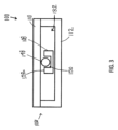
ここで図3~4を参照すると、一実施形態による、被覆ブレード組立品100の概略遠位図および概略側面図が示されている。図3は、被覆ブレード組立品100の近位端102を示す。図示された実施形態では、内側ブレード108は、外側シース106の内側内腔132内に(上部分110と底部分112との間に)位置付けられて示されている。同じく図3に示すように、ボールベアリング148は、内側ブレード108の上面152のポケット150内に位置付けられる。
3-4, there are shown schematic distal and side views of a
図4は、被覆ブレード組立品100の側面図を示す。図示した実施形態では、内側ブレード108は、外側シース106の内側内腔132内に位置付けられる。図4に示す内側ブレード108は、一つのポケット150Aは内側ブレード108の上面152に、一つのポケット150Bは内側ブレード108の底面154にある、二つのポケット150A、150Bを有し、ボールベアリング148は、ポケット150A、150B内に位置付けられている。図示した実施形態では、二つのポケット150A、150Bは、一方のポケット150Aが他方のポケット150Bと比較して内側ブレード108の近位切断端部134に対して遠位にあるようにずらされている。ボールベアリング148はポケット150A、150Bに適合するようにサイズ決めされ、構成され得るが、被覆ブレード組立品100はポケット150A、150Bを必要としない。ボールベアリング148は、外側シース106のサイズおよび外側シース106内の内側ブレード108の幅によって制約され得る。ボールベアリング148のずらされた構成は、内側ブレード108と外側シース106との間に隙間を提供し、組立品内の摩擦を大きく減少させ、それによって熱、摩耗、および金属粒子生成を減少させる。また、隙間により、流体が被覆ブレード組立品100の可動部品を潤滑することが可能になる。
FIG. 4 shows a side view of the
ここで図5~図6を参照すると、代替的な実施形態による、被覆ブレード組立品100の概略上面斜視図および概略分解斜視図が示されている。図5および図6に示す被覆ブレード組立品100の代替的な実施形態において、外側シース106は複数の切欠部146(すなわち、開口または開口部)を含む。図5に示すように、外側シース106の上部分110は、それを通って延びる三つの台形形状または三角形の切欠部156Aを含む。しかしながら、任意の形状または構成の任意の数の切欠部156Aを使用することができる。
Now referring to Figures 5-6, there are shown schematic top perspective and exploded perspective views of a
図6では、外側シース106の底部分112は、それを通って延びる複数の切欠部156B(すなわち、開口または開口部)をさらに含む。外側シース106の底部分112はまた、それを通って延びる三つの台形形状または三角形の切欠部156Bを含む(ただし、任意の形状または構成の任意の数の切欠部156Bを使用することができる)。図示した実施形態では、外側シース106の底部分112の切欠部156Bは、外側シース106の上部分110の切欠部156A内に整列される。切欠部156A、156Bは、内側ブレード108と外側シース106との間の接触の表面積を減少させ、外科手術部位からの流体が可動部品を潤滑することを可能にする。よって、切欠部156A、156Bは、被覆ブレード組立品100内の摩擦および摩耗を減少させ、被覆ブレード組立品100の熱および金属粒子生成を減少させる。摩擦、摩耗、および熱をさらに減少させるために、内側ブレード108および外側シース106の任意の表面はまた、物理的蒸着(PVD)被膜、ダイヤモンド状炭素被膜、および/または二硫化タングステンなどの乾性潤滑被膜などの被膜158を含んでもよい。
6, the
ここで図7を参照すると、一実施形態による、汎用鋸頭部160の概略側面斜視図が示されている。図示した実施形態では、鋸頭部160は、被覆ブレード組立品100(図1)および非被覆(標準)ブレード200の両方を収容するためのコレット162(開口部170を有する)を含む。図1~2に示すように、被覆ブレード100を使用する場合、コレット162は、外部シース106を静止したまま維持する一方、内側ブレード108が内側ブレード108のハブ164を使用して係合および駆動されるように、外側シース106を固定する。非被覆(標準)ブレード200を使用する場合、鋸頭部160は、被覆ブレード組立品100(図2)のハブ164と同じ構造を有しているために、非被覆ブレード組立品200のハブ(図示せず)を使用して非被覆ブレード組立品200を係合および駆動する一方、コレット162は、標準ブレード200が外側シース106の固定に関連付けられた機構のいずれかと接触しないように、十分な隙間を提供する。鋸頭部160は被覆ブレード組立品100(図1)および非被覆(標準)ブレード組立品200の両方を収容できるため、二つの異なるタイプの鋸ハンドピースの必要性が除去され、購入コストおよび在庫が低減する。また、病院や外科センターの物流も改善される。図7に示す通り、単一の汎用鋸頭部160はまた、整形外科手術中の様々な外科手術切除に対するブレードタイプの選択において、ユーザ(例えば、医師)により多くの柔軟性を提供する。
7, a schematic side perspective view of a
図8および9を簡単に参照すると、汎用鋸頭部160に接続された、それぞれ被覆ブレード組立品100および非被覆ブレード200の概略側面斜視図が示されている。図8および図9の両方に示すように、図7の汎用鋸頭部160は、ハンドピース166に取り付けられ得る。ハンドピース166は、電池式ハンドピースまたは空気圧ハンドピースなど、駆動機構を有する任意のハンドピースとし得る。
8 and 9, there is shown a schematic side perspective view of a
図8において、被覆ブレード組立品100が使用される実施形態では、コレット162は、外側シース106の底部分112の遠位端122(図2)においてアーム126を捕捉する。特に、図10に示すように、コレット162上の一つ以上の隆起領域172は、被覆ブレード組立品100の外側シース106をクランプ(または捕捉)し、内側ブレード108が外側シース106内に本質的に浮動する一方で外側シース106を静止させて保持する。よって、コレット162は、同じく図10に示すように、可動内側ブレード108に接触することなく、静止外側シース106に接続する。
8, in an embodiment in which the
図9に示すように、非被覆(標準)ブレード200が使用される場合、コレット162は、非被覆ブレード200のハブ(被覆ブレード組立品100のハブ164(図2)に類似した)に接続されるが、接触、加熱および損傷を防止するために、ブレード200とコレット162との間の隙間量168は残している。図9の隙間量168は、図10に示されるものなど、くぼみ174によってコレット162内に作出され得る。くぼみ174は、コレット162と非被覆ブレード200との間に隙間量168(図9)を提供する。
As shown in FIG. 9, when an uncoated (standard) blade 200 is used, the
図10はまた、コレット162および鋸頭部160の様々な他の構成要素も示す。図示した実施形態では、被覆ブレード組立品100は、キャップ176および従来的なコネクタ178を介してコレット162(および鋸頭部160)に取り付けられる。図示した実施形態では、コネクタ178はキャップ176に取り付けられ、被覆ブレード組立品100のハブ164およびコレット162を通って延びる。図10に示すように、鋸頭部160は駆動ハブ180を含む。駆動ハブ180は、鋸頭部160の可動構成要素である。静止外側シース106がコレット162の隆起領域172によってクランプされると、内側ブレード180は、ハンドピース166内の駆動機構(図示せず)に接続される駆動ハブ180によって駆動、移動、あるいは作動される。
10 also shows various other components of the
本明細書で定義され使用されるすべての定義は、辞書の定義、参照により組み込まれる文書内の定義、および/または定義された用語の通常の意味を制御するために理解されるべきである。 All definitions defined and used herein should be understood to control over dictionary definitions, definitions in documents incorporated by reference, and/or ordinary meanings of the defined terms.
本明細書で様々な実施形態が説明され、図示されてきたが、当業者は、本明細書に記載の機能を実施し、および/または結果および/または一つもしくは複数の利点を得るための様々な他の手段、および/または構造を容易に想起するであろうし、そのような変形および/または変更の各々は、本明細書に記載の実施形態の範囲内であると見なされる。より一般的に、当業者は、本明細書に記載されるすべてのパラメータ、寸法、材料、および構成が、例示的であり、実際のパラメータ、寸法、材料、および/または構成が、教示が使用される一つまたは複数の特定の用途に依存することを容易に理解するであろう。当業者は、本明細書に記載される特定の実施形態に対する多数の同等物を単に通常の実験を用いて認識することができ、または確認することができる。従って、前述の実施形態は、単に例示的なものとして提示されており、添付した特許請求の範囲およびその等価物の範囲内で、実施形態は、具体的に説明および請求された以外のその他の方法で、実行できることが理解されよう。本開示の実施形態は、本明細書に記載される個々の特徴、システム、物品、材料、キット、および/または方法を対象とする。さらに、こうした特徴、システム、物品、材料、キット、および/または方法が相互に矛盾しない場合、二つ以上のこうした特徴、システム、物品、材料、キット、および/または方法の任意の組み合わせが、本開示の範囲内に含まれる。 While various embodiments have been described and illustrated herein, those skilled in the art will readily envision various other means and/or structures for performing the functions and/or obtaining the results and/or one or more advantages described herein, and each such variation and/or modification is deemed to be within the scope of the embodiments described herein. More generally, those skilled in the art will readily appreciate that all parameters, dimensions, materials, and configurations described herein are exemplary, and that the actual parameters, dimensions, materials, and/or configurations will depend on the particular application or applications for which the teachings are used. Those skilled in the art will recognize or be able to ascertain, using no more than routine experimentation, numerous equivalents to the specific embodiments described herein. Thus, the foregoing embodiments are presented merely as illustrative, and it will be understood that, within the scope of the appended claims and their equivalents, the embodiments may be practiced in other ways than as specifically described and claimed. Embodiments of the present disclosure are directed to each individual feature, system, article, material, kit, and/or method described herein. Furthermore, any combination of two or more such features, systems, articles, materials, kits, and/or methods is within the scope of the present disclosure, provided that such features, systems, articles, materials, kits, and/or methods are not mutually inconsistent.
本明細書で使用される用語は、特定の実施形態のみを説明する目的のためであり、本発明を限定することを意図していない。本明細書で使用されるように、単数形「a」、「an」および「the」は、文脈がそうでないことを明確に示さない限り、複数形も含むことが意図される。用語「備える(comprise)」(および「備える(comprises)」や「備える(comprising)」などのcompriseの任意の形式)、「有する(have)」(および「有する(has)」や「有する(having)」などのhaveの任意の形式)、「含む(include)」(および「含む(includes)」や「含む(including)」などのincludeの任意の形式)、および「包含する(contain)」(および「包含する(contains)」や「包含する(containing)」などのcontainの任意の形式)は、オープンエンドのリンク動詞であることがさらに理解されるだろう。結果として、一つまたは複数のステップまたは要素を「備える(comprise)」、「有する(have)」、「含む(include)」または「包含する(contain)」方法またはデバイス。同様に、一つまたは複数の特徴を「備える(comprise)」、「有する(have)」、「含む(include)」または「包含する(contain)」方法のステップ、またはデバイスの要素は、それら一つまたは複数の特徴を有するが、それらの一つまたは複数の特徴のみを保持することに限定されない。さらに、特定の方法で構成されるデバイスまたは構造は、少なくともそのように構成されるが、リストされていない方法で構成することもできる。 The terminology used herein is for the purpose of describing particular embodiments only and is not intended to be limiting of the invention. As used herein, the singular forms "a," "an," and "the" are intended to include the plural forms as well, unless the context clearly indicates otherwise. It will be further understood that the terms "comprise" (and any form of comprise, such as "comprises" or "comprising"), "have" (and any form of have, such as "has" or "having"), "include" (and any form of include, such as "includes" or "including"), and "contain" (and any form of contain, such as "contains" or "containing") are open-ended linking verbs. As a result, a method or device that "comprises," "haves," "includes," or "contains" one or more steps or elements. Similarly, a method step or device element that "comprises," "has," "includes," or "contains" one or more features has those one or more features, but is not limited to possessing only those one or more features. Furthermore, a device or structure that is configured in a particular way is configured in at least that way, but may also be configured in ways not listed.
以下の特許請求の範囲の全ての手段またはステッププラス機能要素の対応する構造、材料、行為および同等物は、もしあれば、具体的に請求される他の特許請求の要素と組み合わせて、機能を実行するための構造、材料または行為を含むことを意図している。本発明の説明は、例示および説明の目的で提示されてきたが、本発明に開示された形態で網羅的または限定されるものではない。多くの修正および変形は、本発明の範囲および趣旨から逸脱することなく、当業者には明らかであろう。実施形態は、本発明の一つまたは複数の態様の原理および実際の応用を最もよく説明し、当業者が、考えられる特定の用途に適した様々な修正を有する様々な実施形態について本発明の一つまたは複数の態様を理解できるように選択および説明された。 The corresponding structures, materials, acts, and equivalents of all means or step-plus-function elements in the following claims are intended to include structures, materials, or acts for performing functions, if any, in combination with elements of other claims that are specifically claimed. The description of the present invention has been presented for purposes of illustration and description, but is not intended to be exhaustive or limited to the invention in the form disclosed. Many modifications and variations will be apparent to those skilled in the art without departing from the scope and spirit of the invention. The embodiments have been selected and described to best explain the principles and practical application of one or more aspects of the invention and to enable those skilled in the art to understand one or more aspects of the invention in various embodiments with various modifications suitable for the particular use contemplated.
Claims (4)
上部分および底部分を有する外側シースであって、前記上部分および前記底部分の間に内側内腔を有する外側シースと、
前記外側シースの前記内側内腔内で移動可能な内側ブレードと、
前記外側シースの前記内側内腔内のベアリングと、
を備え、
前記ベアリングは、前記内側ブレードと前記外側シースの前記上部分および前記底部分のうちの少なくとも一つとの間に隙間量を作出しかつ前記内側ブレードおよび前記外側シースに対して回転するように構成されたボールベアリングであり、
前記内側ブレードの第一の表面内に第一のポケットを備え、
前記ボールベアリングは、前記第一のポケット内に配置されかつ前記内側ブレードの前記第一の表面と前記外側シースの前記底部分との間に隙間量を作出するように構成された第一のボールベアリングであり、
前記内側ブレードの前記第一の表面と対向している第二の表面内に第二のポケットを備え、
前記第二のポケット内に配置された第二のボールベアリングをさらに備え、
前記第二のボールベアリングは、前記内側ブレードの前記第二の表面と前記外側シースの前記上部分との間に隙間量を作出しかつ前記内側ブレードおよび前記外側シースに対して回転するように構成されている、組立品。 a coated braid assembly extending from a proximal end to a distal end,
an outer sheath having a top portion and a bottom portion, the outer sheath having an inner lumen between the top portion and the bottom portion;
an inner blade movable within the inner lumen of the outer sheath;
a bearing within the inner lumen of the outer sheath;
Equipped with
the bearing is a ball bearing configured to rotate relative to the inner blade and the outer sheath and to create a clearance between the inner blade and at least one of the top and bottom portions of the outer sheath;
a first pocket in a first surface of the inner blade;
the ball bearing is a first ball bearing disposed in the first pocket and configured to create a clearance between the first surface of the inner blade and the bottom portion of the outer sheath;
a second pocket in a second surface of the inner blade opposite the first surface;
a second ball bearing disposed within the second pocket;
the second ball bearing creating a clearance between the second surface of the inner blade and the upper portion of the outer sheath and configured to rotate relative to the inner blade and the outer sheath.
Priority Applications (1)
| Application Number | Priority Date | Filing Date | Title |
|---|---|---|---|
| JP2024073763A JP2024097074A (en) | 2018-03-06 | 2024-04-30 | Coated surgical saw blade with bearings |
Applications Claiming Priority (5)
| Application Number | Priority Date | Filing Date | Title |
|---|---|---|---|
| US201862639040P | 2018-03-06 | 2018-03-06 | |
| US62/639,040 | 2018-03-06 | ||
| US201862724914P | 2018-08-30 | 2018-08-30 | |
| US62/724,914 | 2018-08-30 | ||
| PCT/US2019/020677 WO2019173285A1 (en) | 2018-03-06 | 2019-03-05 | Sheathed surgical saw blade with bearings |
Related Child Applications (1)
| Application Number | Title | Priority Date | Filing Date |
|---|---|---|---|
| JP2024073763A Division JP2024097074A (en) | 2018-03-06 | 2024-04-30 | Coated surgical saw blade with bearings |
Publications (2)
| Publication Number | Publication Date |
|---|---|
| JP2021514764A JP2021514764A (en) | 2021-06-17 |
| JP7540945B2 true JP7540945B2 (en) | 2024-08-27 |
Family
ID=65995833
Family Applications (2)
| Application Number | Title | Priority Date | Filing Date |
|---|---|---|---|
| JP2020545634A Active JP7540945B2 (en) | 2018-03-06 | 2019-03-05 | Surgical saw blade with bearings |
| JP2024073763A Pending JP2024097074A (en) | 2018-03-06 | 2024-04-30 | Coated surgical saw blade with bearings |
Family Applications After (1)
| Application Number | Title | Priority Date | Filing Date |
|---|---|---|---|
| JP2024073763A Pending JP2024097074A (en) | 2018-03-06 | 2024-04-30 | Coated surgical saw blade with bearings |
Country Status (8)
| Country | Link |
|---|---|
| US (2) | US11812973B2 (en) |
| EP (2) | EP3909525A1 (en) |
| JP (2) | JP7540945B2 (en) |
| KR (2) | KR102537170B1 (en) |
| CN (1) | CN111989055A (en) |
| AU (3) | AU2019231170B2 (en) |
| CA (2) | CA3151238A1 (en) |
| WO (1) | WO2019173285A1 (en) |
Families Citing this family (1)
| Publication number | Priority date | Publication date | Assignee | Title |
|---|---|---|---|---|
| CA3151238A1 (en) | 2018-03-06 | 2019-09-12 | Conmed Corporation | Sheathed surgical saw blade with bearings |
Citations (2)
| Publication number | Priority date | Publication date | Assignee | Title |
|---|---|---|---|---|
| US5839196A (en) | 1995-11-01 | 1998-11-24 | Linvatec Corporation | Wrenchless collet for surgical blade |
| DE202008017023U1 (en) | 2008-12-16 | 2009-03-05 | Aesculap Ag | Surgical saw and surgical saw |
Family Cites Families (62)
| Publication number | Priority date | Publication date | Assignee | Title |
|---|---|---|---|---|
| US2854981A (en) | 1957-02-18 | 1958-10-07 | Orthopedic Frame Company | Surgical instrument |
| DE2935732A1 (en) | 1979-09-05 | 1981-03-26 | Kienzle Uhrenfabriken GmbH, 78054 Villingen-Schwenningen | Scalpel precision chain drive mechanism - has outlet in blade side-wall near chain run for debris disposal |
| US4617930A (en) | 1984-05-16 | 1986-10-21 | Queen's University At Kingston | Blade stiffener |
| US5087261A (en) | 1988-03-21 | 1992-02-11 | Mit Ab | Saw-blade for sawing living human bone |
| US5178626A (en) | 1989-01-13 | 1993-01-12 | Pappas Michael J | Stepped surgical saw blade |
| US5135533A (en) | 1989-02-10 | 1992-08-04 | Petersen Thomas D | Coated gall-resistant surgical saw blades |
| US5014430A (en) | 1989-09-21 | 1991-05-14 | Wortham Charles D | Plywood saw |
| US5133728A (en) | 1990-01-05 | 1992-07-28 | Petersen Thomas D | Gall-resistant ribbed surgical saw blade |
| US5122142A (en) | 1990-09-13 | 1992-06-16 | Hall Surgical Division Of Zimmer, Inc. | Irrigating saw blade |
| US5263972A (en) * | 1991-01-11 | 1993-11-23 | Stryker Corporation | Surgical handpiece chuck and blade |
| US6503253B1 (en) | 1993-11-16 | 2003-01-07 | Synvasive Technology, Inc. | Surgical saw blade |
| US6022353A (en) | 1991-05-30 | 2000-02-08 | Synasive Technology, Inc. | Surgical saw blade |
| US5382249A (en) | 1991-05-30 | 1995-01-17 | Synvasive Technology, Inc. | Adjustable surgical blade |
| US7527628B2 (en) * | 1991-05-30 | 2009-05-05 | Synvasive Technology, Inc. | Surgical saw blade having at least one pair of opposed teeth shaped as right triangles |
| US5403318A (en) | 1993-01-15 | 1995-04-04 | Boehringer Laboratories, Inc. | Apparatus and method for shaping bone |
| US5306285A (en) | 1993-04-30 | 1994-04-26 | Komet Medical | Surgical saw blade |
| US5507763A (en) | 1993-07-19 | 1996-04-16 | Hall Surgical | Surgical saw blade |
| EP0637433B1 (en) | 1993-08-03 | 1999-09-29 | Ricana AG | Saw blade for making a cut by oscillation or rotation |
| US5366312A (en) | 1993-08-18 | 1994-11-22 | Surgiquip, Inc. | Surgical saw blade attachment assembly |
| US5489285A (en) | 1994-02-23 | 1996-02-06 | Hall Surgical, Div. Of Zimmer, Inc. | Surgical saw blade and clamp |
| US5554165A (en) | 1995-02-09 | 1996-09-10 | Hall Surgical, Div. Of Zimmer, Inc. | Surgical blade and hub |
| JP3738029B2 (en) | 1995-02-28 | 2006-01-25 | ジンテーズ アクチエンゲゼルシャフト,クール | Transmission device that converts rotational motion into reciprocating motion |
| US5728118A (en) | 1995-03-29 | 1998-03-17 | Linvatec Corporation | Apparatus and method for harvesting a bone-tendon-bone ligament graft |
| WO1997010765A1 (en) | 1995-09-18 | 1997-03-27 | Exactech, Inc. | Counter-balanced oscillating surgical saw |
| US5725530A (en) | 1996-06-19 | 1998-03-10 | Popken; John A. | Surgical saw and methods therefor |
| US5735866A (en) | 1996-09-19 | 1998-04-07 | Linvatec Corporation | Adjustable length saw blade |
| US6113618A (en) | 1999-01-13 | 2000-09-05 | Stryker Corporation | Surgical saw with spring-loaded, low-noise cutting blade |
| DE10010526C2 (en) | 2000-03-07 | 2002-01-17 | Thomas Hausmann | Saw blade for medical applications |
| DE10112286C1 (en) | 2001-03-14 | 2002-08-29 | Brasseler Gmbh & Co Kg Geb | Method of making a surgical saw blade |
| DE10112288B4 (en) | 2001-03-14 | 2006-09-07 | Gebr. Brasseler Gmbh & Co. Kg | Surgical saw blade with recesses in the work area |
| DE50208380D1 (en) | 2001-06-25 | 2006-11-23 | Brasseler Gmbh & Co Kg Geb | Surgical saw blade |
| US6875222B2 (en) | 2002-03-12 | 2005-04-05 | Depuy Products, Inc. | Blade for resection of bone for prosthesis implantation, blade stop and method |
| EP1524940B1 (en) * | 2002-03-19 | 2011-08-24 | Bard Dublin ITC Limited | Biopsy device and biopsy needle module that can be inserted into the biopsy device |
| DE10231393A1 (en) | 2002-07-08 | 2004-01-29 | Aesculap Ag & Co. Kg | Surgical saw blade |
| US7189239B2 (en) | 2003-01-14 | 2007-03-13 | Synvasive Technology, Inc. A California Corporation | Saw blade having a prearranged hub section |
| DE10325391A1 (en) | 2003-05-28 | 2004-12-23 | Aesculap Ag & Co. Kg | Surgical saw blade |
| US20040243136A1 (en) | 2003-05-30 | 2004-12-02 | Parag Gupta | Dual cut surgical saw blade |
| US20050245935A1 (en) | 2004-04-29 | 2005-11-03 | Casey Conor P | Surgical saw blade |
| US7497860B2 (en) | 2004-07-09 | 2009-03-03 | Stryker Corporation | Surgical sagittal saw including a handpiece and a removable blade assembly, the blade assembly including a guide bar, a blade head capable of oscillatory movement and a drive rod for actuating the blade head |
| US8932208B2 (en) * | 2005-05-26 | 2015-01-13 | Maquet Cardiovascular Llc | Apparatus and methods for performing minimally-invasive surgical procedures |
| US20070073303A1 (en) | 2005-09-09 | 2007-03-29 | Namba Robert S | Bone-cutting circular saw |
| US7704254B2 (en) * | 2005-09-10 | 2010-04-27 | Stryker Corporation | Surgical sagittal saw with indexing head and toolless blade coupling assembly for actuating an oscillating tip saw blade |
| US7691106B2 (en) * | 2005-09-23 | 2010-04-06 | Synvasive Technology, Inc. | Transverse acting surgical saw blade |
| US7744616B2 (en) | 2005-10-15 | 2010-06-29 | Stryker Ireland, Ltd. | Surgical sagittal saw blade with angled teeth and chip catchment and reciprocating saw blade with broached teeth |
| US7704253B2 (en) | 2006-03-06 | 2010-04-27 | Howmedica Osteonics Corp. | Single use resection guide |
| US20080027449A1 (en) | 2006-07-28 | 2008-01-31 | Depuy Products, Inc. | Adapters to convert output motion of orthopaedic bone saws and bone drills |
| US20080119860A1 (en) | 2006-11-21 | 2008-05-22 | Howmedica Osteonics Corp. | System for preparing bone for receiving an implant |
| US8608745B2 (en) | 2007-03-26 | 2013-12-17 | DePuy Synthes Products, LLC | System, apparatus, and method for cutting bone during an orthopaedic surgical procedure |
| US8920424B2 (en) * | 2008-06-11 | 2014-12-30 | Medtronic Ps Medical, Inc. | Micro-saw blade for bone-cutting surgical saws |
| DE102008063239A1 (en) | 2008-12-16 | 2010-06-17 | Aesculap Ag | Surgical saw blade protection device for knee endoprosthetic application, has insertion opening for opening lateral side and/or distal-side of retaining area for insertion of toothless saw blade section of saw blade |
| DE202008017026U1 (en) | 2008-12-16 | 2009-03-05 | Aesculap Ag | Surgical saw blade guard, surgical saw and surgical saw |
| US8672943B2 (en) * | 2009-05-12 | 2014-03-18 | Synvasive Technology, Inc. | Surgical saw blade device and system |
| US9113946B2 (en) * | 2009-05-26 | 2015-08-25 | Southmedic Incorporated | Blade unit for surgical scalpel |
| WO2011083169A2 (en) | 2010-01-11 | 2011-07-14 | Zimmer Surgical Sa | Surgical blade assembly |
| US8486560B2 (en) | 2010-05-25 | 2013-07-16 | Steven Tartaglia | Battery pack thermal protection from heat sterilization |
| US8449550B2 (en) | 2010-11-10 | 2013-05-28 | Howmedica Osteonics Corp. | IP precision blade guide |
| JP2014527859A (en) | 2011-07-27 | 2014-10-23 | ストライカー・アイルランド・リミテッド | A blade cartridge having a surgical sagittal saw body and a reinforcing rib formed integrally with the blade bar |
| US8936597B2 (en) | 2012-02-06 | 2015-01-20 | Medtronic Ps Medical, Inc. | Deflectable finger connection feature on surgical saw blade |
| CN103505259B (en) * | 2013-10-22 | 2015-12-23 | 重庆西山科技股份有限公司 | The goose saw head assembly of the removable saw blade assembly of orthopaedics |
| US10456142B2 (en) * | 2016-06-03 | 2019-10-29 | Mako Surgical Corp. | Surgical saw and saw blade for use therewith |
| US10687824B2 (en) * | 2017-07-21 | 2020-06-23 | Stryker European Holdings I, Llc | Surgical saw and saw blade for use therewith |
| CA3151238A1 (en) | 2018-03-06 | 2019-09-12 | Conmed Corporation | Sheathed surgical saw blade with bearings |
-
2019
- 2019-03-05 CA CA3151238A patent/CA3151238A1/en active Pending
- 2019-03-05 KR KR1020207025073A patent/KR102537170B1/en active IP Right Grant
- 2019-03-05 JP JP2020545634A patent/JP7540945B2/en active Active
- 2019-03-05 KR KR1020237017409A patent/KR20230079476A/en active IP Right Grant
- 2019-03-05 AU AU2019231170A patent/AU2019231170B2/en active Active
- 2019-03-05 EP EP21171901.8A patent/EP3909525A1/en active Pending
- 2019-03-05 US US16/977,345 patent/US11812973B2/en active Active
- 2019-03-05 CA CA3091362A patent/CA3091362A1/en active Pending
- 2019-03-05 WO PCT/US2019/020677 patent/WO2019173285A1/en unknown
- 2019-03-05 EP EP19714894.3A patent/EP3761890B1/en active Active
- 2019-03-05 CN CN201980017429.2A patent/CN111989055A/en active Pending
-
2022
- 2022-02-21 AU AU2022201157A patent/AU2022201157B2/en active Active
-
2023
- 2023-10-13 US US18/486,280 patent/US20240050101A1/en active Pending
-
2024
- 2024-02-16 AU AU2024201035A patent/AU2024201035A1/en active Pending
- 2024-04-30 JP JP2024073763A patent/JP2024097074A/en active Pending
Patent Citations (2)
| Publication number | Priority date | Publication date | Assignee | Title |
|---|---|---|---|---|
| US5839196A (en) | 1995-11-01 | 1998-11-24 | Linvatec Corporation | Wrenchless collet for surgical blade |
| DE202008017023U1 (en) | 2008-12-16 | 2009-03-05 | Aesculap Ag | Surgical saw and surgical saw |
Also Published As
| Publication number | Publication date |
|---|---|
| US20210100561A1 (en) | 2021-04-08 |
| CN111989055A (en) | 2020-11-24 |
| WO2019173285A1 (en) | 2019-09-12 |
| KR102537170B1 (en) | 2023-05-26 |
| JP2021514764A (en) | 2021-06-17 |
| US20240050101A1 (en) | 2024-02-15 |
| US11812973B2 (en) | 2023-11-14 |
| AU2019231170A1 (en) | 2020-09-03 |
| AU2019231170B2 (en) | 2021-12-02 |
| AU2022201157B2 (en) | 2023-11-16 |
| AU2022201157A1 (en) | 2022-03-17 |
| EP3909525A1 (en) | 2021-11-17 |
| CA3091362A1 (en) | 2019-09-12 |
| EP3761890B1 (en) | 2024-06-12 |
| JP2024097074A (en) | 2024-07-17 |
| EP3761890A1 (en) | 2021-01-13 |
| AU2024201035A1 (en) | 2024-03-07 |
| CA3151238A1 (en) | 2019-09-12 |
| KR20200118457A (en) | 2020-10-15 |
| KR20230079476A (en) | 2023-06-07 |
Similar Documents
| Publication | Publication Date | Title |
|---|---|---|
| JP2024097074A (en) | Coated surgical saw blade with bearings | |
| US11389572B2 (en) | High temperature material for use in medical devices | |
| JP6949087B2 (en) | The most usable surgical instrument with a disposable tip and an integrated tip cover | |
| US8394116B2 (en) | Surgical tools and components thereof | |
| US8313502B2 (en) | Endoscopic cutting instruments having improved cutting efficiency and reduced manufacturing costs | |
| US20230255657A1 (en) | Surgical devices and systems with rotating end effector assemblies having an ultrasonic blade | |
| KR102645918B1 (en) | Surgical devices and systems having rotating end effector assemblies with ultrasonic blades | |
| US20210153890A1 (en) | Surgical devices and systems with rotating end effector assemblies having an ultrasonic blade | |
| JP2007532253A (en) | Saw blade | |
| JP2007532253A5 (en) | ||
| JP2012504432A5 (en) | ||
| JP5951805B2 (en) | Ratchet for medical field, method for manufacturing ratchet, and torque transmission system | |
| WO2017176683A1 (en) | Articulating endodontic file | |
| US9486232B2 (en) | Endoscopic cutting instruments having improved efficiency and reduced manufacturing costs | |
| EP4358878A1 (en) | Surgical cutting instrument, rotational joint and method, particularly for robotic surgery and/or micro-surgery | |
| US20240016566A1 (en) | Articulated surgical instrument for robotic surgery or microsurgery, manufacturing method and assembly method | |
| WO2021100379A1 (en) | Endoscope clip system | |
| WO2010093773A1 (en) | Cast removal device | |
| JP2021087462A (en) | Medical device |
Legal Events
| Date | Code | Title | Description |
|---|---|---|---|
| A621 | Written request for application examination |
Free format text: JAPANESE INTERMEDIATE CODE: A621 Effective date: 20200918 |
|
| A131 | Notification of reasons for refusal |
Free format text: JAPANESE INTERMEDIATE CODE: A131 Effective date: 20210817 |
|
| A601 | Written request for extension of time |
Free format text: JAPANESE INTERMEDIATE CODE: A601 Effective date: 20211116 |
|
| A521 | Request for written amendment filed |
Free format text: JAPANESE INTERMEDIATE CODE: A523 Effective date: 20220117 |
|
| A131 | Notification of reasons for refusal |
Free format text: JAPANESE INTERMEDIATE CODE: A131 Effective date: 20220614 |
|
| A601 | Written request for extension of time |
Free format text: JAPANESE INTERMEDIATE CODE: A601 Effective date: 20220913 |
|
| A521 | Request for written amendment filed |
Free format text: JAPANESE INTERMEDIATE CODE: A523 Effective date: 20220920 |
|
| A02 | Decision of refusal |
Free format text: JAPANESE INTERMEDIATE CODE: A02 Effective date: 20230117 |
|
| A521 | Request for written amendment filed |
Free format text: JAPANESE INTERMEDIATE CODE: A523 Effective date: 20230516 |
|
| A911 | Transfer to examiner for re-examination before appeal (zenchi) |
Free format text: JAPANESE INTERMEDIATE CODE: A911 Effective date: 20230523 |
|
| A912 | Re-examination (zenchi) completed and case transferred to appeal board |
Free format text: JAPANESE INTERMEDIATE CODE: A912 Effective date: 20230616 |
|
| A521 | Request for written amendment filed |
Free format text: JAPANESE INTERMEDIATE CODE: A523 Effective date: 20240430 |
|
| A601 | Written request for extension of time |
Free format text: JAPANESE INTERMEDIATE CODE: A601 Effective date: 20240808 |
|
| A61 | First payment of annual fees (during grant procedure) |
Free format text: JAPANESE INTERMEDIATE CODE: A61 Effective date: 20240815 |
|
| R150 | Certificate of patent or registration of utility model |
Ref document number: 7540945 Country of ref document: JP Free format text: JAPANESE INTERMEDIATE CODE: R150 |