JP7536639B2 - Cleaning System - Google Patents

Cleaning System Download PDF

Info

Publication number
JP7536639B2
JP7536639B2 JP2020218837A JP2020218837A JP7536639B2 JP 7536639 B2 JP7536639 B2 JP 7536639B2 JP 2020218837 A JP2020218837 A JP 2020218837A JP 2020218837 A JP2020218837 A JP 2020218837A JP 7536639 B2 JP7536639 B2 JP 7536639B2
Authority
JP
Japan
Prior art keywords
rack
lift
dish rack
dishwasher
detection
Prior art date
Legal status (The legal status is an assumption and is not a legal conclusion. Google has not performed a legal analysis and makes no representation as to the accuracy of the status listed.)
Active
Application number
JP2020218837A
Other languages
Japanese (ja)
Other versions
JP2022103921A (en
Inventor
祐也 木全
友裕 ▲高▼木
史幸 堀
Current Assignee (The listed assignees may be inaccurate. Google has not performed a legal analysis and makes no representation or warranty as to the accuracy of the list.)
Hoshizaki Corp
Original Assignee
Hoshizaki Corp
Priority date (The priority date is an assumption and is not a legal conclusion. Google has not performed a legal analysis and makes no representation as to the accuracy of the date listed.)
Filing date
Publication date
Application filed by Hoshizaki Corp filed Critical Hoshizaki Corp
Priority to JP2020218837A priority Critical patent/JP7536639B2/en
Publication of JP2022103921A publication Critical patent/JP2022103921A/en
Application granted granted Critical
Publication of JP7536639B2 publication Critical patent/JP7536639B2/en
Active legal-status Critical Current
Anticipated expiration legal-status Critical

Links

Images

Landscapes

  • Washing And Drying Of Tableware (AREA)
  • Warehouses Or Storage Devices (AREA)

Description

本発明は、洗浄システムに関する。 The present invention relates to a cleaning system.

洗浄機に食器(被洗浄物)が収容されたラックを搬入する搬入装置と、食器を洗浄する洗浄機と、上下方向に配列されると共にラックを収容可能な棚部を有するワゴンと、洗浄機によって洗浄された食器をワゴンにおける棚部に搬入するリフト装置と、洗浄機から押し出してリフト装置に搬出させる搬出装置と、を備えた洗浄システムが知られている。 A washing system is known that includes a loading device that loads a rack containing dishes (items to be washed) into a washing machine, a washing machine that washes the dishes, a cart that is arranged vertically and has shelves capable of accommodating the racks, a lift device that loads the dishes washed by the washing machine onto the shelves in the cart, and an unloading device that pushes the dishes out of the washing machine and removes them to the lift device.

特開平3-41922号公報Japanese Patent Application Publication No. 3-41922

例えば、特許文献1には、洗浄機の前方からラックを搬入させ、洗浄機の左方からラックを搬出させる洗浄システムが開示されている。このような洗浄システムでは、洗浄機からリフト装置の所定位置にラックを確実に搬送させることが求められている。 For example, Patent Document 1 discloses a cleaning system in which a rack is loaded into the front of the cleaning machine and unloaded from the left side of the cleaning machine. In such a cleaning system, it is required to reliably transport the rack from the cleaning machine to a predetermined position on the lift device.

そこで、本発明の目的は、洗浄機からリフト装置の所定位置にラックを確実に搬送させることができる、洗浄システムを提供することにある。 The object of the present invention is to provide a cleaning system that can reliably transport racks from a cleaning machine to a specified position on a lift device.

本発明の洗浄システムは、洗浄室に収容される被洗浄物を洗浄する洗浄機と、洗浄機に被洗浄物を収容するラックを搬入する搬入装置と、洗浄機から搬出されるラックをワゴンに搬入するリフト装置と、洗浄機からリフト装置にラックを搬出する搬出装置と、を備えた洗浄システムであって、リフト装置は、ラックを鉛直方向に搬送するリフト部であって、ラックの被係止部に係止部を引っ掛けたラックをリフト部に引き込む搬送ベルトを有するリフト部と、洗浄機からリフト部へラックが進入したことを検知する第一検知部と、搬送ベルトの引き込み方向において第一検知部の検知位置よりも下流側の所定位置にラックが搬送されてきたことを検知する第二検知部と、を有し、洗浄システムは、リフト部を制御する制御部を更に備え、制御部は、第一検知部による検知が有ると搬送ベルトによる引き込みを開始させ、第一検知部による検知から所定時間経過後に第二検知部による検知が無い場合には、リフト部を所定量上昇させる。 The cleaning system of the present invention is a cleaning system that includes a cleaning machine that cleans objects stored in a cleaning chamber, a loading device that loads racks that store objects to be cleaned into the cleaning machine, a lift device that loads racks that are to be removed from the cleaning machine into a wagon, and a loading device that loads racks from the cleaning machine to the lift device. The lift device is a lift section that transports racks in a vertical direction and has a conveyor belt that pulls racks with their engaging parts hooked onto the engaged parts of the racks into the lift section, a first detector that detects that the rack has entered the lift section from the cleaning machine, and a second detector that detects that the rack has been transported to a predetermined position downstream of the detection position of the first detector in the retracting direction of the conveyor belt. The cleaning system further includes a control section that controls the lift section, and the control section starts retraction by the conveyor belt when the first detector detects, and raises the lift section by a predetermined amount when there is no detection by the second detector after a predetermined time has elapsed since the detection by the first detector.

洗浄機からリフト装置にラックが搬入されるとき、例えば、ラックに収容された被洗浄物の偏り等が原因となって、ラックの被係止部が想定よりも上方に位置する事象が発生することがある。この場合、搬送ベルトに形成された係止部はラックの被係止部に係止されず、ラックをリフト部に引き込むことができない。本発明の洗浄システムでは、第一検知部による検知から所定時間経過後に第二検知部による検知が無い場合には、リフト部を所定量上昇させるので、リフト部に搬入されたラックに上述したような事象が発生していたとしても、ラックの被係止部に係止部を係止させることができる。これにより、洗浄機からリフト部の所定位置に食器ラックを確実に搬送させることができる。 When a rack is transported from the washer to the lift device, for example, an event may occur in which the locked portion of the rack is positioned higher than expected due to uneven distribution of items to be washed on the rack. In this case, the locking portion formed on the conveyor belt does not lock onto the locked portion of the rack, and the rack cannot be pulled into the lift section. In the washing system of the present invention, if there is no detection by the second detection section a predetermined time after detection by the first detection section, the lift section is raised a predetermined amount, so that even if an event such as that described above occurs with a rack transported into the lift section, the locking portion can be locked onto the locked portion of the rack. This allows the dish rack to be reliably transported from the washer to the predetermined position on the lift section.

本発明の洗浄システムでは、制御部は、搬入装置によってラックが洗浄機へ搬入されているときに、リフト部が鉛直方向に移動することを規制してもよい。ここで、洗浄機にラックを搬入するときに意図せずにリフト装置側に食器ラックが飛び出した場合、下降してくるリフト部にラックが上方から挟まれたりする不具合が発生するおそれがある。この構成では、搬入装置によってラックが洗浄機へ搬入されているときに、リフト部が鉛直方向に移動することを規制するので、意図せずにリフト装置側に食器ラックが飛び出すことがあったとしても、上記のような不具合の発生を低減することができる。 In the washing system of the present invention, the control unit may restrict the lift unit from moving vertically when the rack is being carried into the washing machine by the carrying-in device. Here, if the dish rack unintentionally projects toward the lift unit when carrying the rack into the washing machine, there is a risk of a malfunction in which the rack is pinched from above by the descending lift unit. In this configuration, since the lift unit is restricted from moving vertically when the rack is being carried into the washing machine by the carrying-in device, the occurrence of such a malfunction can be reduced even if the dish rack unintentionally projects toward the lift unit.

本発明によれば、食器洗浄機から搬送リフトの所定位置に食器ラックを確実に搬送させることができる。 According to the present invention, the dish rack can be reliably transported from the dishwasher to a designated position on the transport lift.

図1は、一実施形態に係る洗浄システムの全体を示した斜視図である。FIG. 1 is a perspective view showing an entire cleaning system according to one embodiment. 図2(A)は、キャリーテーブルの正面図であり、図2(B)は、キャリーテーブルの平面図である。FIG. 2A is a front view of the carry table, and FIG. 2B is a plan view of the carry table. 図3は、食器洗浄機の概略構成を示す断面図である。FIG. 3 is a cross-sectional view showing a schematic configuration of the dishwasher. 図4(A)は、リフト装置をワゴン側から見た側面図であり、図4(B)は、リフト装置を食器洗浄機側から見た側面図である。FIG. 4(A) is a side view of the lift device as viewed from the wagon side, and FIG. 4(B) is a side view of the lift device as viewed from the dishwasher side. 図5(A)は、リフト装置のリフト部を拡大して示した斜視図であり、図5(B)は、リフト部の搬送ベルトを拡大して示した斜視図である。FIG. 5A is an enlarged perspective view of a lift portion of the lift device, and FIG. 5B is an enlarged perspective view of a conveyor belt of the lift portion. 図6は、ワゴンを示す斜視図である。FIG. 6 is a perspective view showing a wagon. 図7(A)は、搬出装置の平面図であり、図7(B)は、搬出装置の斜視図である。FIG. 7A is a plan view of the discharge device, and FIG. 7B is a perspective view of the discharge device. 図8(A)及び図8(B)は、搬出装置による食器ラックの搬出を説明する平面図である。8(A) and 8(B) are plan views illustrating the removal of the dish rack by the removal device. 図9は、食器洗浄機の洗浄室の斜視断面図である。FIG. 9 is a perspective cross-sectional view of the washing chamber of a dishwasher. 図10は、ラックレールの斜視図である。FIG. 10 is a perspective view of the rack rail. 図11は、洗浄システムの機能構成を示した機能ブロックである。FIG. 11 is a functional block diagram showing the functional configuration of the cleaning system. 図12は、リフト装置の動作を説明するフローチャートである。FIG. 12 is a flowchart illustrating the operation of the lift device. 図13(A)及び図13(B)は、リフト装置の動作を説明する図である。13(A) and 13(B) are diagrams illustrating the operation of the lift device.

以下、添付図面を参照して、本発明の好適な実施形態について詳細に説明する。なお、図面の説明において同一又は相当要素には同一符号を付し、重複する説明は省略する。図面の寸法比率は、説明のものと必ずしも一致していない。以下の説明においては、図1で規定する方向(上下方向、前後方向、左右方向)を説明に用いる。 A preferred embodiment of the present invention will be described in detail below with reference to the attached drawings. In the description of the drawings, the same or equivalent elements are given the same reference numerals, and duplicated description will be omitted. The dimensional ratios of the drawings do not necessarily match those in the description. In the following description, the directions (up-down direction, front-back direction, left-right direction) defined in Figure 1 will be used for explanation.

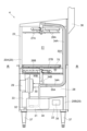
図1に示されるように、洗浄システム1は、キャリーテーブル(搬入装置)3と、食器洗浄機(洗浄機)4と、リフト装置5と、ワゴン6と、搬出装置90と、を備えている。洗浄システム1では、キャリーテーブル3及び食器洗浄機4が前後方向に並べて配置され、食器洗浄機4、リフト装置5及びワゴン6が、左右方向に並べて配置されている。すなわち、本実施形態の洗浄システム1では、食器(被洗浄物)が収容される食器ラック(ラック)Rが前側から後側に向かって移動した後、右側から左側に向かって移動するように、平面視においてキャリーテーブル3、食器洗浄機4、リフト装置5及びワゴン6がL字状に配置されている。 As shown in FIG. 1, the washing system 1 includes a carry table (carry-in device) 3, a dishwasher (cleaning machine) 4, a lift device 5, a wagon 6, and an unloading device 90. In the washing system 1, the carry table 3 and the dishwasher 4 are arranged side by side in the front-to-back direction, and the dishwasher 4, the lift device 5, and the wagon 6 are arranged side by side in the left-to-right direction. That is, in the washing system 1 of this embodiment, the carry table 3, the dishwasher 4, the lift device 5, and the wagon 6 are arranged in an L-shape in a plan view so that the dish rack (rack) R on which the dishes (items to be washed) are stored moves from the front to the rear, and then moves from the right to the left.

キャリーテーブル3は、食器ラックRを食器洗浄機4に搬送する。図1及び図2に示されるように、キャリーテーブル3は、基台10と、基台10を支持する四つの脚部19と、搬送機構11と、センサ14と、コントローラ(制御部)12と、アーム検知センサ13と、を有している。 The carry table 3 transports the dish rack R to the dishwasher 4. As shown in Figures 1 and 2, the carry table 3 has a base 10, four legs 19 that support the base 10, a transport mechanism 11, a sensor 14, a controller (control unit) 12, and an arm detection sensor 13.

基台10は、食器ラックRが載置されるテーブルである。基台10は、食器ラックRが載置される載置面10aを有している。基台10には、載置面10aから突出すると共に食器ラックRの搬送方向に沿って延在する、食器ラックRを摺動させる摺動部16が設けられている。摺動部16は、載置面10aにねじ等によって固定された、例えば、ポリアセタール樹脂により形成されたプレート状の部材によって構成されている。摺動部16は、食器ラックRに対する摺動性を良好にする部材であれば材料を問わず、ポリアセタール樹脂以外の材料によっても形成が可能である。 The base 10 is a table on which the dish rack R is placed. The base 10 has a mounting surface 10a on which the dish rack R is placed. The base 10 is provided with a sliding part 16 that protrudes from the mounting surface 10a and extends along the conveying direction of the dish rack R, allowing the dish rack R to slide. The sliding part 16 is composed of a plate-shaped member made of, for example, polyacetal resin, fixed to the mounting surface 10a with screws or the like. The sliding part 16 can be made of any material as long as it provides good sliding properties with respect to the dish rack R, and can also be made of materials other than polyacetal resin.

搬送機構11は、食器ラックRを基台10上で移動させる。搬送機構11は、アーム部材11Aと、支持部11Bと、チェーン11Cと、スプロケット11D,11Dと、第一モータ11Eと、を有している。搬送機構11は、ハウジング17に収容されている。ハウジング17は、キャリーテーブル3を正面から見たとき基台10の後方に配置されており、基台10の載置面10aよりも上方に突出して設けられている。 The transport mechanism 11 moves the dish rack R on the base 10. The transport mechanism 11 has an arm member 11A, a support portion 11B, a chain 11C, sprockets 11D, 11D, and a first motor 11E. The transport mechanism 11 is housed in a housing 17. When the carry table 3 is viewed from the front, the housing 17 is disposed behind the base 10 and protrudes above the placement surface 10a of the base 10.

アーム部材11Aは、食器ラックRを押し出す部材であって、載置面10a上を回動可能となるように、支持部11Bに支持されている。支持部11Bは、チェーン11Cに平行に配置されたガイドレール(図示せず)に沿って前後方向に移動可能に設けられると共に、チェーン11Cの一部に固定的に連結されている。チェーン11C,11Cは、二つのスプロケット11D,11Dに巻回されている。第一モータ11Eは、例えばギアモータである。第一モータ11Eの回転軸には、一方のスプロケット11Dが軸支されている。 The arm member 11A is a member that pushes out the dish rack R, and is supported by the support portion 11B so that it can rotate on the placement surface 10a. The support portion 11B is provided so that it can move in the front-rear direction along a guide rail (not shown) that is arranged parallel to the chain 11C, and is fixedly connected to a part of the chain 11C. The chains 11C, 11C are wound around two sprockets 11D, 11D. The first motor 11E is, for example, a gear motor. One of the sprockets 11D is supported on the rotating shaft of the first motor 11E.

アーム部材11Aは、アーム部材11Aの先端が食器洗浄機4側(後側)に向く状態とキャリーテーブル3の手前側(左側)に向く状態との間で回動可能となるように、ねじりバネ(図示せず)を介して支持部11Bに固定されている。ねじりバネは、平面視において半時計回り(左回り)に回動する方向にアーム部材11Aを付勢している。すなわち、ねじりバネは、ハウジング17から進出する方向にアーム部材11Aを付勢している。アーム部材11Aは、ねじりバネの作用によってシャッタ(図示せず)等の規制部材に接触しない限り、ハウジング17の外側である載置面10a上の進出領域に進出するようになっている。アーム部材11Aは、平面視において載置面10aに重複する進出領域と、載置面10aから退避した退避領域との間で移動可能に設けられており、食器ラックRの押し出しをしないときには、退避領域に退避されている。 The arm member 11A is fixed to the support portion 11B via a torsion spring (not shown) so that the tip of the arm member 11A can rotate between a state in which it faces the dishwasher 4 side (rear side) and a state in which it faces the front side (left side) of the carry table 3. The torsion spring biases the arm member 11A in a direction to rotate counterclockwise (left direction) in a plan view. In other words, the torsion spring biases the arm member 11A in a direction to advance from the housing 17. The arm member 11A advances to an advance area on the placement surface 10a, which is outside the housing 17, unless it comes into contact with a regulating member such as a shutter (not shown) due to the action of the torsion spring. The arm member 11A is provided so as to be movable between an advance area overlapping the placement surface 10a in a plan view and an evacuation area retreated from the placement surface 10a, and is retreated to the evacuation area when the dish rack R is not being pushed out.

アーム部材11Aは、第一モータ11Eによって駆動されるスプロケット11D及びチェーン11Cに連動することによって、キャリーテーブル3を正面から見たときの左右方向に回動する。アーム部材11Aは、食器ラックRを搬送するときに、ハウジング17内から載置面10a上に進出し、待機状態においてはハウジング17内に退避する。より詳細には、アーム部材11Aは、載置面10a上の食器ラックRの食器洗浄機4側への回動がセンサ14によって検知されたタイミング、又は、操作部18においてスタートボタンB1が押下されたタイミングで載置面10a上に進出する。 The arm member 11A rotates left and right when viewed from the front of the carry table 3 by linking with a sprocket 11D and a chain 11C driven by a first motor 11E. When transporting a dish rack R, the arm member 11A advances from within the housing 17 onto the placement surface 10a, and retracts into the housing 17 in a standby state. More specifically, the arm member 11A advances onto the placement surface 10a when the sensor 14 detects the rotation of the dish rack R on the placement surface 10a towards the dishwasher 4, or when the start button B1 on the operation unit 18 is pressed.

アーム部材11Aは、食器洗浄機4に向けて食器ラックRを押し出す。アーム部材11Aの先端、すなわち、食器ラックRに当接する部分には、ベアリング(図示せず)が設けられもよい。アーム部材11Aは、食器ラックRを食器洗浄機4にまで搬送すると(すなわち、食器ラックRを押し出す押出位置に到達すると)、ハウジング17の内部の退避領域の一部である待機位置に戻る。 The arm member 11A pushes out the dish rack R towards the dishwasher 4. A bearing (not shown) may be provided at the tip of the arm member 11A, i.e., the portion that abuts against the dish rack R. When the arm member 11A transports the dish rack R to the dishwasher 4 (i.e., when it reaches the pushing position where it pushes out the dish rack R), it returns to a standby position that is part of the retreat area inside the housing 17.

アーム部材11Aは、左右方向において右側を基点として左側に延在している。本実施形態では、アーム部材11Aの左側端部は、載置面10aの左右方向における中心位置CLよりも右側に位置している。なお、アーム部材11Aの左端は、右側を基点として上記中心位置CLよりも左側にまで延びていてもよい。この場合、アーム部材11Aは、載置面10aに載置される食器ラックRの左右方向における中心位置よりも左側の部分まで接触して、食器洗浄機4側に押し出すことができる。 The arm member 11A extends leftward from the right side as a base point in the left-right direction. In this embodiment, the left end of the arm member 11A is located to the right of the center position CL of the mounting surface 10a in the left-right direction. The left end of the arm member 11A may also extend leftward from the center position CL using the right side as a base point. In this case, the arm member 11A can contact the dish rack R placed on the mounting surface 10a up to a portion to the left of the center position in the left-right direction, and push it toward the dishwasher 4.

コントローラ12は、キャリーテーブル3を含む、洗浄システム1の動作全般を制御する。コントローラ12は、外部との信号の入出力等を行う入出力インタフェイス、処理を行うためのプログラム及び情報等が記憶されたROM(Read Only Memory)、データを一時的に記憶するRAM(Random Access Memory)等の記憶媒体、CPU(Central Processing Unit)、及び通信回路等を有する。コントローラ12は、CPUが出力する信号に基づいて、入力データをRAMに記憶し、ROMに記憶されているプログラムをRAMにロードし、RAMにロードされたプログラムを実行することで各種処理を実行する。コントローラ12は、例えば、キャリーテーブル3の動作、食器洗浄機4におけるドア23の開閉動作、搬出装置90の動作、リフト装置5の動作等を制御する。コントローラ12は、例えば、ハウジング17内に収容されている。 The controller 12 controls the overall operation of the washing system 1, including the carry table 3. The controller 12 has an input/output interface for inputting and outputting signals from and to the outside, a storage medium such as a ROM (Read Only Memory) in which programs and information for performing processing are stored, a RAM (Random Access Memory) for temporarily storing data, a CPU (Central Processing Unit), and a communication circuit. The controller 12 stores input data in the RAM based on a signal output by the CPU, loads a program stored in the ROM into the RAM, and executes the program loaded into the RAM to perform various processes. The controller 12 controls, for example, the operation of the carry table 3, the opening and closing of the door 23 in the dishwasher 4, the operation of the discharge device 90, the operation of the lift device 5, and the like. The controller 12 is housed, for example, in a housing 17.

図11に示されるように、コントローラ12は、アーム検知センサ13と、食器洗浄機4のコントローラ35と、リフト装置5の第一センサ(第一検知部)44A及び第二センサ(第二検知部)44Bと、キャリーテーブル3の第一モータ11Eと、搬出装置90の第二モータ93と、通信可能に接続されている。 As shown in FIG. 11, the controller 12 is communicatively connected to the arm detection sensor 13, the controller 35 of the dishwasher 4, the first sensor (first detection unit) 44A and the second sensor (second detection unit) 44B of the lift device 5, the first motor 11E of the carry table 3, and the second motor 93 of the discharge device 90.

図2に戻り、操作部18は、ハウジング17を形成するパネルの一部に配置されている。操作部18には、搬送機構11の動作を開始させるスタートボタンB1、搬送機構11の動作を停止させる停止ボタンB2、及び作業者に音声で各種状態を報知するスピーカ等の報知部Mが配置されている。 Returning to FIG. 2, the operation unit 18 is disposed in a part of the panel forming the housing 17. The operation unit 18 is provided with a start button B1 for starting the operation of the transport mechanism 11, a stop button B2 for stopping the operation of the transport mechanism 11, and a notification unit M such as a speaker for notifying the operator of various conditions by voice.

アーム検知センサ13は、所定の位置にアーム部材11Aが移動してきたことを検知する。本実施形態のアーム検知センサ13は、アーム部材11Aが食器洗浄機4の洗浄室21に食器ラックRの搬入を完了するときのアーム部材11Aの位置を検知するように配置されている、すなわち、アーム検知センサ13は、食器洗浄機4の洗浄室21に食器ラックRの搬入が完了したことを検知する。アーム検知センサ13の検知結果(ラック搬入完了通知)は、コントローラ12によって取得される。 The arm detection sensor 13 detects that the arm member 11A has moved to a predetermined position. In this embodiment, the arm detection sensor 13 is positioned to detect the position of the arm member 11A when the arm member 11A completes the loading of the dish rack R into the washing chamber 21 of the dishwasher 4; that is, the arm detection sensor 13 detects that the loading of the dish rack R into the washing chamber 21 of the dishwasher 4 has been completed. The detection result of the arm detection sensor 13 (rack loading completion notification) is acquired by the controller 12.

図1に示されるように、食器洗浄機4は、キャリーテーブル3の後側に、キャリーテーブル3に隣接して配置されている。食器洗浄機4は、食器ラックRに収容されている食器を洗浄する。図1及び図3に示されるように、食器洗浄機4は、ステンレス製のパネルで覆われた洗浄機本体20を有している。洗浄機本体20は、洗浄室21が形成された上側部分20Aと、機械室22が形成された下側部分20Bとに仕切られている。 As shown in FIG. 1, the dishwasher 4 is disposed adjacent to the carry table 3 on the rear side thereof. The dishwasher 4 washes dishes stored in the dish rack R. As shown in FIG. 1 and FIG. 3, the dishwasher 4 has a washing machine body 20 covered with a stainless steel panel. The washing machine body 20 is divided into an upper portion 20A in which a washing chamber 21 is formed, and a lower portion 20B in which a machine chamber 22 is formed.

洗浄機本体20の上側部分20Aには、洗浄室21の開閉を行うための箱型のドア23が設けられている。ドア23は、後段にて詳述する連結部材64(図4(A)参照)に連結されている。連結部材64は、コントローラ12によって制御される駆動モータ60(図4(A)参照)によって駆動される。ドア23は、駆動モータ60による駆動によって、上下方向において最下高さ位置に位置して、洗浄室21を閉じる閉位置(図4に示す位置)と、上下方向において最高高さ位置に位置して、洗浄室21を開く開位置(図1に示す位置)と、の間で移動する。なお、本実施形態のドア23には設けられていないが、手動でドア23を開閉するハンドルが設けられてもよい。 The upper part 20A of the washer body 20 is provided with a box-shaped door 23 for opening and closing the cleaning chamber 21. The door 23 is connected to a connecting member 64 (see FIG. 4A), which will be described in detail later. The connecting member 64 is driven by a drive motor 60 (see FIG. 4A), which is controlled by the controller 12. The door 23 is driven by the drive motor 60 to move between a closed position (position shown in FIG. 4) in which the door 23 is located at the lowest height position in the vertical direction and closes the cleaning chamber 21, and an open position (position shown in FIG. 1) in which the door 23 is located at the highest height position in the vertical direction and opens the cleaning chamber 21. Although not provided on the door 23 in this embodiment, a handle for manually opening and closing the door 23 may be provided.

洗浄室21内には、食器ラックRが載置されるラックレール70が着脱自在に配置されている。キャリーテーブル3から食器洗浄機4に搬出される食器ラックRは、ラックレール70上に押し出される。洗浄室21の上部には、放射状に延びる3本のアームからなる上側洗浄ノズル26Aと、2本のアームからなる上側すすぎノズル27Aとがそれぞれ回転自在に配置されている。同様に、洗浄室21の下部には、放射状に延びる3本のアームからなる下側洗浄ノズル26Bと、2本のアームからなる下側すすぎノズル27Bとがそれぞれ回転自在に配置されている。食器ラックRに並べられた食器は、上側洗浄ノズル26A及び下側洗浄ノズル26Bによって上下から洗浄水が噴射され、上側すすぎノズル27A及び下側すすぎノズル27Bによって上下からすすぎ水が噴射される。 In the washing chamber 21, a rack rail 70 on which the dish rack R is placed is detachably arranged. The dish rack R that is carried from the carrying table 3 to the dishwasher 4 is pushed onto the rack rail 70. In the upper part of the washing chamber 21, an upper washing nozzle 26A consisting of three radially extending arms and an upper rinsing nozzle 27A consisting of two arms are each rotatably arranged. Similarly, in the lower part of the washing chamber 21, a lower washing nozzle 26B consisting of three radially extending arms and a lower rinsing nozzle 27B consisting of two arms are each rotatably arranged. The dishes arranged on the dish rack R are sprayed with washing water from above and below by the upper washing nozzle 26A and the lower washing nozzle 26B, and rinsing water is sprayed from above and below by the upper rinsing nozzle 27A and the lower rinsing nozzle 27B.

洗浄水タンク28には、洗浄水吸込口を介して洗浄ポンプ29が接続されている。洗浄ポンプ29の吐出口には、洗浄水吐出管30が接続されている。洗浄水吐出管30は、第一洗浄水吐出管30Aと第二洗浄水吐出管30Bとに分岐して、第一洗浄水吐出管30Aは上側洗浄ノズル26Aに接続され、第二洗浄水吐出管30Bは下側洗浄ノズル26Bに接続されている。 A cleaning pump 29 is connected to the cleaning water tank 28 via a cleaning water suction port. A cleaning water discharge pipe 30 is connected to the discharge port of the cleaning pump 29. The cleaning water discharge pipe 30 branches into a first cleaning water discharge pipe 30A and a second cleaning water discharge pipe 30B, with the first cleaning water discharge pipe 30A connected to the upper cleaning nozzle 26A and the second cleaning water discharge pipe 30B connected to the lower cleaning nozzle 26B.

機械室22内には、外部から給水管(図示せず)を介してすすぎ水が供給されるすすぎ水タンク31が配置されている。すすぎ水タンク31には、すすぎ水吸込管32を介してすすぎポンプ33が接続されている。すすぎポンプ33の吐出口には、すすぎ水吐出管34が接続されている。すすぎ水吐出管34は、第一すすぎ水吐出管34Aと第二すすぎ水吐出管34Bとに分岐して、第一すすぎ水吐出管34Aは上側すすぎノズル27Aに接続され、第二すすぎ水吐出管34Bは下側すすぎノズル27Bに接続されている。第一すすぎ水吐出管34Aは、第一洗浄水吐出管30A内に配置されている。すなわち、第一洗浄水吐出管30A及び第一すすぎ水吐出管34Aは、二重管構造を成している。 A rinse water tank 31 is disposed in the machine room 22, to which rinse water is supplied from the outside via a water supply pipe (not shown). A rinse pump 33 is connected to the rinse water tank 31 via a rinse water suction pipe 32. A rinse water discharge pipe 34 is connected to the discharge port of the rinse pump 33. The rinse water discharge pipe 34 branches into a first rinse water discharge pipe 34A and a second rinse water discharge pipe 34B, with the first rinse water discharge pipe 34A being connected to the upper rinse nozzle 27A and the second rinse water discharge pipe 34B being connected to the lower rinse nozzle 27B. The first rinse water discharge pipe 34A is disposed within the first cleaning water discharge pipe 30A. That is, the first cleaning water discharge pipe 30A and the first rinse water discharge pipe 34A form a double pipe structure.

機械室22内には、食器洗浄機4の動作全般を制御するコントローラ35が内蔵された電装ボックス(図示せず)等が収容されている。コントローラ35は、洗浄が終了したことを示す洗浄終了信号を、キャリーテーブル3のコントローラ12に出力する。 The machine room 22 contains an electrical box (not shown) with a built-in controller 35 that controls the overall operation of the dishwasher 4. The controller 35 outputs a cleaning end signal, indicating that cleaning has ended, to the controller 12 of the carry table 3.

食器洗浄機4は、熱交換ユニット36を備えている。熱交換ユニット36は、洗浄機本体20の洗浄室21から排出された水蒸気を凝縮して、水蒸気の包含量が減少した空気を外部に排出する。食器洗浄機4は、洗浄機本体20を支持する四つの脚部37を備えている。 The dishwasher 4 is equipped with a heat exchange unit 36. The heat exchange unit 36 condenses the water vapor discharged from the washing chamber 21 of the washing machine main body 20 and discharges the air containing a reduced amount of water vapor to the outside. The dishwasher 4 is equipped with four legs 37 that support the washing machine main body 20.

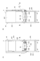
図1に示されるように、リフト装置5は、食器洗浄機4の左隣りに、食器洗浄機4に隣接して配置されている。リフト装置5は、食器洗浄機4から搬出された食器ラックRを、ワゴン6の所定位置に移載する。図4(A)及び図4(B)に示されるように、リフト装置5は、本体40と、リフタ(リフト部)41と、ドア駆動機構7と、第三モータ49Aを含むリフト駆動機構(詳細は図示せず)と、第一センサ44Aと、第二センサ44Bと、を備えている。本体40は、フレーム40Aと、前後方向において互いに対向して配置されている一対の側部42A,42Bを有している。一対の側部42A,42Bは、パネル状の部材である。本体40は、一対の側部42A,42Bの対向方向に直交する水平方向の両側が開口している。本体40には、食器洗浄機4側の開口の上側の一部を覆う側部42Cが設けられている。リフト装置5は、本体40を支持する四つの脚部47を備えている。 As shown in FIG. 1, the lift device 5 is disposed adjacent to the dishwasher 4 to the left. The lift device 5 transfers the dish rack R removed from the dishwasher 4 to a predetermined position on the wagon 6. As shown in FIG. 4(A) and FIG. 4(B), the lift device 5 includes a main body 40, a lifter (lift section) 41, a door drive mechanism 7, a lift drive mechanism (details not shown) including a third motor 49A, a first sensor 44A, and a second sensor 44B. The main body 40 has a frame 40A and a pair of side sections 42A, 42B arranged opposite each other in the front-rear direction. The pair of side sections 42A, 42B are panel-shaped members. The main body 40 is open on both sides in the horizontal direction perpendicular to the opposing direction of the pair of side sections 42A, 42B. The main body 40 is provided with a side section 42C that covers a part of the upper side of the opening on the dishwasher 4 side. The lift device 5 has four legs 47 that support the main body 40.

リフタ41は、リフト駆動機構によって、上下方向に移動する。リフト駆動機構は、第三モータ49Aの他、スプロケット、チェーン等を含んで構成されている。図5(A)に示されるように、リフタ41は、食器ラックRをリフト装置5の内側に引き込むと共に、食器ラックRをワゴン6に搬出する搬送ベルト43A,43Bを有している。搬送ベルト43A,43Bは、無端ベルトであって、図示しないスプロケット等に架け渡されている。そして、搬送ベルト43A,43Bは、第四モータ49Bの他、スプロケット、チェーン等を含んで構成されている駆動機構によって一方向D1に回転可能に構成されている。 The lifter 41 moves up and down by a lift drive mechanism. The lift drive mechanism includes a third motor 49A, sprockets, chains, etc. As shown in FIG. 5(A), the lifter 41 has conveyor belts 43A, 43B that pull the dish rack R into the inside of the lift device 5 and transport the dish rack R to the cart 6. The conveyor belts 43A, 43B are endless belts that are stretched over sprockets, etc. (not shown). The conveyor belts 43A, 43B are configured to be rotatable in one direction D1 by a drive mechanism that includes a fourth motor 49B, sprockets, chains, etc.

図5(B)に示されるように、搬送ベルト43A,43Bには、突起部(係止部)48が設けられている。突起部48は、図13(A)及び図13(A)に示されるように、食器ラックRの被係止部Raに引っ掛ける部材である。図5(A)及び図5(B)に示されるように、突起部48は、搬送ベルト43A,43Bの長手方向に沿って所定の間隔で設けられている。搬送ベルト43A,43Bは、食器ラックRを突起部48に引っ掛けた状態で一方向D1に回転することによって、食器ラックRをリフタ41の所定位置、すなわち第二センサ44Bによって検知される位置にまで引き込む。被係止部Raは、食器ラックRの縁部(通常状態で搬送ベルト43A,43Bに載置されたとき搬送ベルト43A,43Bにおいて接触する枠状部分)及び食器ラックRの底面に形成される凹部等、突起部48に係止される部分である。 As shown in FIG. 5(B), the conveyor belts 43A and 43B are provided with protrusions (engagement parts) 48. As shown in FIG. 13(A) and FIG. 13(A), the protrusions 48 are members that hook onto the engaged parts Ra of the dish rack R. As shown in FIG. 5(A) and FIG. 5(B), the protrusions 48 are provided at a predetermined interval along the longitudinal direction of the conveyor belts 43A and 43B. The conveyor belts 43A and 43B rotate in one direction D1 with the dish rack R hooked onto the protrusions 48, thereby drawing the dish rack R to a predetermined position of the lifter 41, that is, to a position detected by the second sensor 44B. The engaged parts Ra are parts that are engaged with the protrusions 48, such as the edge of the dish rack R (the frame-shaped part that contacts the conveyor belts 43A and 43B when placed on the conveyor belts 43A and 43B in the normal state) and a recess formed on the bottom surface of the dish rack R.

図4(A)及び図4(B)に戻り、第一センサ44Aは、食器洗浄機4からリフト装置5へ食器ラックRが進入したことを検知する。第一センサ44Aは、例えば、リフタ41の食器洗浄機4側の端部に設けられている。第二センサ44Bは、搬送ベルト43A,43Bの引き込み方向(一方向D1)において第一センサ44Aの検知位置よりも下流側の所定位置に食器ラックRが搬送されてきたことを検知する。第二センサ44Bは、例えば、リフタ41のワゴン6側の端部に近い位置に設けられている。 Returning to Figures 4(A) and 4(B), the first sensor 44A detects that the dish rack R has entered the lift device 5 from the dishwasher 4. The first sensor 44A is provided, for example, at the end of the lifter 41 on the dishwasher 4 side. The second sensor 44B detects that the dish rack R has been transported to a predetermined position downstream of the detection position of the first sensor 44A in the retraction direction (direction D1) of the conveyor belts 43A and 43B. The second sensor 44B is provided, for example, at a position close to the end of the lifter 41 on the wagon 6 side.

コントローラ12は、第一センサ44Aによる検知が有ると搬送ベルト43A,43Bによる引き込みを開始させ、搬送ベルト43A,43Bによる検知から所定時間経過後(例えば、10秒)に第二センサ44Bによる検知が無い場合には、リフタ41を所定量H(例えば、1cm~5cm)上昇させる。上記所定時間及びリフタ41の上昇量は、食器ラックRの被係止部Raの形状、突起部48の突出量、食器ラックRが食器洗浄機4からリフト装置5に搬入されるときに食器ラックRに生じる可能性のある傾きの範囲等に基づいて、適宜設定され得る。 When the first sensor 44A detects something, the controller 12 starts retracting the conveyor belts 43A and 43B, and when the second sensor 44B detects nothing a predetermined time (e.g., 10 seconds) after the first sensor 44A detects something, the controller 12 raises the lifter 41 a predetermined amount H (e.g., 1 cm to 5 cm). The predetermined time and the amount of lift of the lifter 41 can be set appropriately based on the shape of the engaging portion Ra of the dish rack R, the amount of protrusion of the protrusion 48, the range of tilt that may occur in the dish rack R when the dish rack R is transported from the dishwasher 4 to the lift device 5, etc.

コントローラ12は、リフタ41を所定量H上昇させた後、第二センサ44Bによる検知があると、リフタ41を搬入予定のワゴン6の段と同じ高さまで上昇させる。また、コントローラ12は、キャリーテーブル3によって食器ラックRが食器洗浄機4へ搬入されているときに、リフト装置5のリフタ41が鉛直方向に移動することを規制(禁止)する。すなわち、コントローラ12は、アーム部材11Aを動かす第一モータ11Eとリフタ41を昇降させる第三モータ49Aとが同時に駆動しないように制御する。 After lifting the lifter 41 a predetermined amount H, when the second sensor 44B detects it, the controller 12 raises the lifter 41 to the same height as the stage of the cart 6 to be loaded. The controller 12 also restricts (prohibits) the lifter 41 of the lift device 5 from moving vertically when the dish rack R is being loaded into the dishwasher 4 by the carry table 3. In other words, the controller 12 controls the first motor 11E that moves the arm member 11A and the third motor 49A that raises and lowers the lifter 41 so that they are not driven simultaneously.

ドア駆動機構7は、食器洗浄機4のドア23を閉位置及び開位置に駆動させる。ドア駆動機構7は、駆動モータ60と、一対のスプロケット(図示せず)と、チェーン(図示せず)と、スライダ63と、連結部材64と、を有している。ドア駆動機構7は、リフト装置5の背面側に設けられている。 The door drive mechanism 7 drives the door 23 of the dishwasher 4 to a closed position and an open position. The door drive mechanism 7 has a drive motor 60, a pair of sprockets (not shown), a chain (not shown), a slider 63, and a connecting member 64. The door drive mechanism 7 is provided on the rear side of the lift device 5.

駆動モータ60は、例えば、ギアモータである。駆動モータ60は、例えば、リフト装置5の上部に配置されている。駆動モータ60の動作は、キャリーテーブル3のコントローラ12によって制御される。スプロケットには、駆動モータ60の出力軸が接続されている。スプロケットは、スプロケットの回転に応じて、チェーンを介して従動して回転する。チェーンは、一対のスプロケットに掛け渡されている。 The drive motor 60 is, for example, a gear motor. The drive motor 60 is, for example, disposed on the upper part of the lift device 5. The operation of the drive motor 60 is controlled by the controller 12 of the carry table 3. The output shaft of the drive motor 60 is connected to a sprocket. The sprocket rotates in response to the rotation of the sprocket via a chain. The chain is stretched around a pair of sprockets.

スライダ63は、チェーンに接続されている。スライダ63は、チェーンの移動に応じて上下方向に移動する。スライダ63は、上下方向に沿って延在しているガイドレール65に接続されており、ガイドレール65に沿って移動する。連結部材64は、スライダ63とドア23とを連結している。連結部材64は、前後方向に沿って延在している。連結部材64の一端部は、スライダ63に固定されており、連結部材64の他端部は、軸ピン(図示せず)を介してドア23に連結されている。連結部材64には、支持部材(図示せず)が設けられている。支持部材は、連結部材64とドア23の下端部とに接続されており、ドア23が上昇するときにドア23を下方から支持する。 The slider 63 is connected to a chain. The slider 63 moves up and down in response to the movement of the chain. The slider 63 is connected to a guide rail 65 extending in the up and down direction, and moves along the guide rail 65. The connecting member 64 connects the slider 63 to the door 23. The connecting member 64 extends in the front-rear direction. One end of the connecting member 64 is fixed to the slider 63, and the other end of the connecting member 64 is connected to the door 23 via a pivot pin (not shown). The connecting member 64 is provided with a support member (not shown). The support member is connected to the connecting member 64 and the lower end of the door 23, and supports the door 23 from below when the door 23 rises.

ドア駆動機構7には、食器洗浄機4のドア23が開位置に到達したときに位置するスライダ63を検知するセンサ、及び、ドア23が閉位置に到達したときに位置するスライダ63を検知するセンサが設けられている。これらのセンサの検知結果を取得するコントローラ12は、ドア23が閉位置(下降位置)にある状態と、開位置(上昇位置)にある状態とを区別して検知することができる。 The door drive mechanism 7 is provided with a sensor that detects the slider 63 positioned when the door 23 of the dishwasher 4 reaches the open position, and a sensor that detects the slider 63 positioned when the door 23 reaches the closed position. The controller 12 that acquires the detection results of these sensors can distinguish between the state in which the door 23 is in the closed position (lowered position) and the state in which it is in the open position (raised position).

図1に示されるように、ワゴン6は、リフト装置5の左隣りに、リフト装置5に隣接して配置されている。ワゴン6は、複数(本実施形態では4個)の食器ラックRを収納可能である。ワゴン6は、リフト装置5によって食器ラックRが収容される。ワゴン6は、リフト装置5に着脱可能に設けられている。 As shown in FIG. 1, the wagon 6 is disposed adjacent to the lift device 5 to the left of the lift device 5. The wagon 6 can store multiple (four in this embodiment) dish racks R. The wagon 6 stores the dish racks R by the lift device 5. The wagon 6 is detachably attached to the lift device 5.

図6に示されるように、ワゴン6は、互いに対向して配置されている一対の側部50A,50Bと、一対の側部50A,50Bの上端部に設けられている上部51と、一対の側部50A,50Bの下端部に設けられている底部52と、を有している。一対の側部50A,50Bは、パネル状の部材により形成されている。ワゴン6は、一対の側部50A,50B、上部51及び底部52によって、食器ラックRを収容する収容空間が形成されている。ワゴン6は、一対の側部50A,50Bの対向方向に直交する水平方向の両側が開口している。 As shown in FIG. 6, the wagon 6 has a pair of side portions 50A, 50B arranged opposite each other, an upper portion 51 provided at the upper end of the pair of side portions 50A, 50B, and a bottom portion 52 provided at the lower end of the pair of side portions 50A, 50B. The pair of side portions 50A, 50B are formed from panel-like members. In the wagon 6, a storage space for storing a dish rack R is formed by the pair of side portions 50A, 50B, the upper portion 51, and the bottom portion 52. The wagon 6 is open on both sides in the horizontal direction perpendicular to the opposing direction of the pair of side portions 50A, 50B.

一対の側部50A,50Bのそれぞれの内面には、互いに対向する位置に、一対の支持レール53A,53Bが設けられている。一対の支持レール53A,53Bは、食器ラックRを支持する。一対の支持レール53A,53Bは、ワゴン6において食器ラックRを収容する棚部を構成している。支持レール53A,53Bは、上下方向において所定の間隔をあけて複数配置されている。一方の側部50Aの外面には、作業者によって把持可能な操作ハンドル54A,54Bが設けられている。底部52には、ワゴン6がリフト装置5から取り外されたときにワゴン6を移動自在とする4個のローラ55A,55B,55C,55Dと、ワゴン6がリフト装置5に取り付けられたときにワゴン6を設置(固定)する設置機構56A,56Bと、が設けられている。 A pair of support rails 53A, 53B are provided on the inner surface of each of the pair of side parts 50A, 50B at positions facing each other. The pair of support rails 53A, 53B support the dish rack R. The pair of support rails 53A, 53B form a shelf part in the wagon 6 that stores the dish rack R. A plurality of support rails 53A, 53B are arranged at a predetermined interval in the vertical direction. The outer surface of one of the side parts 50A is provided with operation handles 54A, 54B that can be held by an operator. The bottom part 52 is provided with four rollers 55A, 55B, 55C, 55D that allow the wagon 6 to move freely when the wagon 6 is removed from the lift device 5, and installation mechanisms 56A, 56B that install (fix) the wagon 6 when the wagon 6 is attached to the lift device 5.

搬出装置90は、食器洗浄機4からリフト装置5に食器ラックRを搬出する。図7(A)に示されるように、搬出装置90は、食器洗浄機4に右側側面の前方に設けられている。図7(B)に示されるように、搬出装置90は、アーム91と、第二モータ93と、規制部96と、を有している。 The discharge device 90 discharges the dish rack R from the dishwasher 4 to the lift device 5. As shown in FIG. 7(A), the discharge device 90 is provided at the front of the right side of the dishwasher 4. As shown in FIG. 7(B), the discharge device 90 has an arm 91, a second motor 93, and a regulating unit 96.

アーム91は、図8(A)及び図8(B)に示されるように、一方向に延在する回動軸91Aを回動中心に回動することでラックレール70に載置された食器ラックRをリフト装置5に押し出す。アーム91によって押し出された食器ラックRはラックレール70を摺動し、食器洗浄機4からリフト装置5に搬出される。アーム91は、回動軸91Aを中心に回転可能に設けられると共に、食器ラックRに接触可能に設けられた第一ベアリング92A及び第二ベアリング92Bを有している。 As shown in Figures 8(A) and 8(B), the arm 91 pushes the dish rack R placed on the rack rail 70 into the lift device 5 by rotating the pivot shaft 91A extending in one direction as the center of rotation. The dish rack R pushed by the arm 91 slides along the rack rail 70 and is transported from the dishwasher 4 to the lift device 5. The arm 91 is rotatable around the pivot shaft 91A and has a first bearing 92A and a second bearing 92B that are arranged to be in contact with the dish rack R.

第二モータ93は、出力軸である回動軸91Aを中心に、待機位置と押出位置との間でアーム91を回動させる。待機位置は、食器ラックRを押し出す前のアーム91が待機している位置である。押出位置は、待機位置から回動軸91Aを中心に回動して食器ラックRを洗浄室21から搬出させたときのアーム91の位置である。規制部96は、原点位置に位置するアーム91に対し、押出位置とは反対側に配置されている。規制部96は、原点位置よりも逆方向に回転しようとするアーム91の動作を規制する。 The second motor 93 rotates the arm 91 between a standby position and a push-out position around the output shaft, the pivot shaft 91A. The standby position is where the arm 91 waits before pushing out the dish rack R. The push-out position is where the arm 91 is positioned when it rotates from the standby position around the pivot shaft 91A to transport the dish rack R out of the washing chamber 21. The restricting portion 96 is disposed on the opposite side of the arm 91, which is positioned at the origin position, from the push-out position. The restricting portion 96 restricts the movement of the arm 91 that attempts to rotate in the opposite direction from the origin position.

コントローラ12は、第二センサ44Bによって食器ラックRが検知される(すなわち、食器洗浄機4から食器ラックRの搬出が完了したことが検知される)と、次の食器ラックRの搬入を開始するように、キャリーテーブル3のアーム部材11Aを移動させる第一モータ11Eを制御する。 When the second sensor 44B detects the dish rack R (i.e., when it detects that the dish rack R has been completely removed from the dishwasher 4), the controller 12 controls the first motor 11E to move the arm member 11A of the carry table 3 so as to start loading the next dish rack R.

図9に示されるように、ラックレール70は、ステンレス鋼によって形成される枠体であり、食器洗浄機4に着脱自在に取り付けられている。ここで、洗浄水タンク28は、貯留部形成部28aと、平面部28bと、を有している。貯留部形成部28aは、洗浄水を貯留する貯留部を形成する。平面部28bは、上方から見た平面視において貯留部形成部28aの周囲に形成され、略水平方向に延出する部分である。ラックレール70は、後段にて詳述する第一支持部76が、平面部28bに載置される。 As shown in FIG. 9, the rack rail 70 is a frame formed of stainless steel, and is removably attached to the dishwasher 4. Here, the cleaning water tank 28 has a reservoir forming portion 28a and a flat portion 28b. The reservoir forming portion 28a forms a reservoir that stores cleaning water. The flat portion 28b is formed around the reservoir forming portion 28a in a plan view from above, and extends in a substantially horizontal direction. The rack rail 70 has a first support portion 76, which will be described in detail later, placed on the flat portion 28b.

ラックレール70を食器洗浄機4から取り外した状態を図10に示す。図10に示されるように、ラックレール70は、食器洗浄機4に配置されたときに、キャリーテーブル3が接続される方向に配置される第一載置部71と、リフト装置5が接続される方向に配置される第二載置部72と、第二載置部72と対向かつ第一載置部71に交差する第三載置部73と、第一載置部71に対向かつ第二載置部72及び第三載置部73に交差する第四載置部74と、を含む枠部70Aを有している。ラックレール70は、一対の第一支持部76,76と、一対の第二支持部77,77と、側面案内部78と、を更に有している。 Figure 10 shows the rack rail 70 removed from the dishwasher 4. As shown in Figure 10, when the rack rail 70 is placed in the dishwasher 4, it has a frame portion 70A including a first mounting portion 71 arranged in the direction to which the carry table 3 is connected, a second mounting portion 72 arranged in the direction to which the lift device 5 is connected, a third mounting portion 73 facing the second mounting portion 72 and intersecting with the first mounting portion 71, and a fourth mounting portion 74 facing the first mounting portion 71 and intersecting with the second mounting portion 72 and the third mounting portion 73. The rack rail 70 further has a pair of first support portions 76, 76, a pair of second support portions 77, 77, and a side guide portion 78.

第四載置部74は、互いに対向する第二載置部72及び第三載置部73間を接続する部材であり、洗浄室21に配置されたとき、食器洗浄機4の後側に配置される部材である。第四載置部74は、中実状又は中空パイプ状の丸棒である。 The fourth mounting portion 74 is a member that connects the opposing second mounting portion 72 and third mounting portion 73, and is a member that is disposed at the rear side of the dishwasher 4 when placed in the washing chamber 21. The fourth mounting portion 74 is a solid or hollow pipe-shaped round bar.

一対の第一支持部76,76は、ラックレール70が洗浄室21に配置されたとき、洗浄室21の前側下部に配置される第一載置部71に固定されている。一対の第一支持部76,76は、第一載置部71の左右方向の左側と右側とに配置されている。一対の第一支持部76,76のそれぞれは、第一載置部71から下方に延びる第一部分76a,76aと、第一部分76a,76aから前側に屈曲すると共に、ラックレール70が洗浄室21に配置されたとき、洗浄水タンク28の平面部28bに載置される第二部分76bを有する。第一支持部76,76は、中実状又は中空パイプ状の丸棒によって形成されている。 The pair of first support parts 76, 76 are fixed to a first mounting part 71 that is arranged at the front lower part of the cleaning chamber 21 when the rack rail 70 is arranged in the cleaning chamber 21. The pair of first support parts 76, 76 are arranged on the left and right sides of the first mounting part 71 in the left-right direction. Each of the pair of first support parts 76, 76 has a first part 76a, 76a extending downward from the first mounting part 71, and a second part 76b that bends forward from the first part 76a, 76a and is placed on the flat part 28b of the cleaning water tank 28 when the rack rail 70 is arranged in the cleaning chamber 21. The first support parts 76, 76 are formed from a solid or hollow pipe-shaped round bar.

一対の第二支持部77,77の一方は第二載置部72に接続され、一対の第二支持部77,77の他方は第三載置部73に接続されている。一対の第二支持部77,77の一方は、第二載置部72から斜め左後方に延びる第一部分77aと、左右方向に延在する第二部分77bと、を有している。一対の第二支持部77,77の他方は、第三載置部73から斜め右後方に延びる第一部分77aと、左右方向に延在する第二部分77bと、を有している。一対の第二支持部77,77は、それぞれ棒状に形成されている。第二部分77b,77bの端部のそれぞれは、洗浄室21に設けられる図示しない係止部材に、双方向に回転可能かつ着脱可能に係止されている。側面案内部78は、食器ラックRをガイドする部材であり、洗浄室21に搬入時の食器ラックRの右方向への逸脱を防止する。 One of the pair of second support parts 77, 77 is connected to the second placement part 72, and the other of the pair of second support parts 77, 77 is connected to the third placement part 73. One of the pair of second support parts 77, 77 has a first part 77a extending diagonally left rear from the second placement part 72 and a second part 77b extending in the left-right direction. The other of the pair of second support parts 77, 77 has a first part 77a extending diagonally right rear from the third placement part 73 and a second part 77b extending in the left-right direction. Each of the pair of second support parts 77, 77 is formed in a rod shape. Each of the ends of the second parts 77b, 77b is engaged with an engaging member (not shown) provided in the washing chamber 21 so as to be rotatable in both directions and detachable. The side guide part 78 is a member that guides the dish rack R and prevents the dish rack R from deviating to the right when being carried into the washing chamber 21.

次に、リフト装置5の動作について説明する。リフタ41は、食器洗浄機4による洗浄が完了した際、食器洗浄機4のラックレール70(図3参照)と同じ高さ位置(原点位置)で待機している。リフタ41は、食器洗浄機4から搬出装置90によって食器ラックRが搬出されて、食器ラックRの一部がリフタ41上に位置したことが第一センサ44Aで検知されると、搬送ベルト43A,43Bの作動を開始する。これにより、食器ラックRは、搬送ベルト43A,43Bの突起部48が引っ掛けられた状態で、リフタ41の所定位置(第二センサ44Bの検出位置)まで引き込まれる。 Next, the operation of the lift device 5 will be described. When washing by the dishwasher 4 is completed, the lifter 41 waits at the same height position (origin position) as the rack rail 70 of the dishwasher 4 (see Figure 3). When the dish rack R is removed from the dishwasher 4 by the discharge device 90 and the first sensor 44A detects that part of the dish rack R is positioned on the lifter 41, the lifter 41 starts operating the conveyor belts 43A and 43B. As a result, the dish rack R is pulled into a predetermined position on the lifter 41 (detection position of the second sensor 44B) with the protrusions 48 of the conveyor belts 43A and 43B hooked.

ここで、突起部48が食器ラックRに係止されず、所定時間の間、食器ラックRが引き込まれない場合には、リフタ41が所定量H上昇する。これにより、突起部48が食器ラックRに引っ掛かり、搬送ベルト43A,43Bによってリフタ41における所定位置(第二センサ44Bの検出位置)まで引き込まれる。リフタ41は、食器ラックRを上記所定位置まで引き込むと、ワゴン6において食器ラックRが収容されていない棚部(段)に食器ラックRを移載する。リフタ41は、搬送ベルト43A,43Bを作動させて、食器ラックRをワゴン6に送り出す。ワゴン6の各棚部における空き状況は、リフト装置5の、例えば、天板及び底板に設けられたセンサ(図示せず)又はリフタ41に設けられたセンサ44Cによって検知される。 Here, if the protrusion 48 is not engaged with the dish rack R and the dish rack R is not retracted for a predetermined time, the lifter 41 rises a predetermined amount H. As a result, the protrusion 48 is caught by the dish rack R and is retracted to a predetermined position (detection position of the second sensor 44B) on the lifter 41 by the conveyor belts 43A and 43B. When the lifter 41 retracts the dish rack R to the predetermined position, it transfers the dish rack R to a shelf (tier) on the wagon 6 that does not house the dish rack R. The lifter 41 operates the conveyor belts 43A and 43B to send the dish rack R to the wagon 6. The availability of each shelf on the wagon 6 is detected by, for example, sensors (not shown) provided on the top and bottom plates of the lift device 5 or a sensor 44C provided on the lifter 41.

次に、食器洗浄機4へ食器ラックRを搬入するときのリフト装置5の動きについて、主に図12を参照しながら説明する。ここでは、食器洗浄機4が被洗浄物を洗浄中に、次の洗浄対象となる食器ラックRがキャリーテーブル3にセット(予約設定)されている場合を例に挙げて説明する。 Next, the movement of the lift device 5 when the dish rack R is carried into the dishwasher 4 will be described mainly with reference to FIG. 12. Here, an example will be described in which the dish rack R to be next washed is set (reserved) on the carry table 3 while the dishwasher 4 is washing the items to be washed.

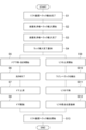
上述したリフト装置5の動作によって、リフト装置5へ食器ラックRの搬出が完了すると(第二センサ44Bが検知すると)(ステップS1)、キャリーテーブル3は、アーム部材11Aの移動させる第一モータ11Eを駆動させ、食器洗浄機4へ次の洗浄対象となる食器ラックRの搬入を開始する(ステップS2)。食器洗浄機4へ食器ラックRの搬入が完了(第一モータ11Eの一連の動作が終了)し(ステップS3)、アーム検知センサ13によってアーム部材11Aが検知される(ラック搬入完了通知が発出される)と(ステップS4)、食器洗浄機4のドア23が下降し、搬入された食器ラックRに収容された被洗浄物の洗浄を開始する(ステップS5)。食器洗浄機4における洗浄が終了すると(ステップS6)、ドア23の上昇が開始される(ステップS7)。 When the above-mentioned operation of the lift device 5 completes the unloading of the dish rack R to the lift device 5 (when the second sensor 44B detects it) (step S1), the carry table 3 drives the first motor 11E that moves the arm member 11A, and starts the loading of the next dish rack R to be washed into the dishwasher 4 (step S2). When the loading of the dish rack R into the dishwasher 4 is completed (a series of operations of the first motor 11E is completed) (step S3) and the arm detection sensor 13 detects the arm member 11A (a rack loading completion notification is issued) (step S4), the door 23 of the dishwasher 4 descends, and the washing of the items stored in the loaded dish rack R begins (step S5). When the washing in the dishwasher 4 is completed (step S6), the door 23 begins to rise (step S7).

また、アーム検知センサ13によってアーム部材11Aが検知される(ラック搬入完了通知が発出される)と(ステップS4)、リフト装置5は、リフタ41の上昇を開始し(ステップS9)、ワゴン6の所定の段に食器ラックRを搬出する(ステップS10)。リフタ41は、食器洗浄機4のドア23が下降完了(閉位置に移動)したこと確認した後に下降する(ステップS11)。なお、ステップS4におけるリフタ41の下降完了が所定時間検知されない場合には、エラーとして少なくとも食器洗浄機4及びリフト装置5の動作が停止する。ステップS7の後にドアが開放し(ステップS8)、かつステップS11の後にリフタ41が原点位置に復帰すると(ステップS12)、搬出装置90は、食器洗浄機4からリフト装置5への食器ラックRの搬出を開始する(ステップS13)。 When the arm member 11A is detected by the arm detection sensor 13 (a rack loading completion notification is issued) (step S4), the lift device 5 starts raising the lifter 41 (step S9) and carries the dish rack R to a predetermined level of the cart 6 (step S10). The lifter 41 descends after confirming that the door 23 of the dishwasher 4 has completed its descent (moved to the closed position) (step S11). If the completion of the descent of the lifter 41 in step S4 is not detected for a predetermined period of time, an error occurs and at least the operation of the dishwasher 4 and the lift device 5 is stopped. When the door opens after step S7 (step S8) and the lifter 41 returns to the origin position after step S11 (step S12), the carrying out device 90 starts carrying the dish rack R from the dishwasher 4 to the lift device 5 (step S13).

上記実施形態の洗浄システム1における作用効果について説明する。食器洗浄機4からリフト装置5に食器ラックRが搬入されるとき、例えば、図13(A)に示されるように、食器ラックRに収容された被洗浄物の偏り等が原因となって、食器ラックRの被係止部Raが想定よりも上方に位置する事象が発生することがある。この場合、搬送ベルト43A,43Bに形成された突起部48は食器ラックRの被係止部Raに係止されず、食器ラックRをリフタ41に引き込むことができない。上記実施形態の洗浄システム1では、第一センサ44Aによる検知から所定時間経過後に第二センサ44Bによる検知が無い場合には、リフタ41を所定量H上昇させるので、リフタ41に搬入された食器ラックRに上述したような事象が発生していたとしても、図13(B)に示されるように、食器ラックRの被係止部Raに突起部48を係止させることができる。これにより、食器洗浄機4からリフタ41の所定位置に食器ラックRを確実に搬送させることができる。 The effects of the washing system 1 of the above embodiment will be described. When the dish rack R is carried into the lift device 5 from the dishwasher 4, for example, as shown in FIG. 13(A), due to the unevenness of the objects to be washed stored in the dish rack R, the hooked portion Ra of the dish rack R may be located higher than expected. In this case, the protrusions 48 formed on the conveyor belts 43A and 43B are not hooked to the hooked portion Ra of the dish rack R, and the dish rack R cannot be pulled into the lifter 41. In the washing system 1 of the above embodiment, if there is no detection by the second sensor 44B after a predetermined time has elapsed since the detection by the first sensor 44A, the lifter 41 is raised by a predetermined amount H. Therefore, even if the above-mentioned event occurs in the dish rack R carried into the lifter 41, the protrusions 48 can be hooked to the hooked portion Ra of the dish rack R as shown in FIG. 13(B). This allows the dish rack R to be reliably transported from the dishwasher 4 to a predetermined position on the lifter 41.

ここで、食器洗浄機4に食器ラックRを搬入するときに意図せずにリフト装置5側に食器ラックRが飛び出した場合、下降してくるリフタ41に食器ラックRが上方から挟まれて、食器ラックRに破損や変形が生じる不具合が発生するおそれがある。意図せずにリフト装置5側に食器ラックRが飛び出すのは、図10に示されるように、リフト装置5に隣接するラックレール70左側の第二載置部72には、食器洗浄機4からリフト装置5へ食器ラックRを摺動させるために、ラックレール70右側の第三載置部73のように側面案内部78が設けられていないためである。 Here, if the dish rack R unintentionally projects toward the lift device 5 when the dish rack R is being carried into the dishwasher 4, the dish rack R may be pinched from above by the descending lifter 41, causing a malfunction in which the dish rack R is damaged or deformed. The dish rack R unintentionally projects toward the lift device 5 because, as shown in FIG. 10, the second mounting portion 72 on the left side of the rack rail 70 adjacent to the lift device 5 does not have a side guide portion 78, like the third mounting portion 73 on the right side of the rack rail 70, for sliding the dish rack R from the dishwasher 4 to the lift device 5.

上記実施形態の洗浄システム1では、キャリーテーブル3によって食器ラックRが食器洗浄機4へ搬入されているときに、リフタ41が鉛直方向に移動することを規制するので、意図せずにリフト装置5側に食器ラックRが飛び出すことがあったとしても、上記のような不具合の発生を防止することができる。詳細には、アーム部材11Aによって食器洗浄機4の洗浄室21に搬入され、アーム検知センサ13によってアーム部材11Aが検知され(ラック搬入完了通知が発出される)たとき、仮にリフト装置5側に食器ラックRが飛び出すことがあったとしても、リフタ41は、ドア23が下降完了したこと(閉状態となったこと)を確認した後に下降を開始するので、リフタ41が飛び出した食器ラックRを上方から挟むことを防止できる。また、ドア23が下降してこないことは、ドア23の下降開始から下降完了までの時間を監視することによってエラーとして検知されるので、同様に、リフタ41が食器ラックRを上方から挟まれることを防止できる。 In the washing system 1 of the above embodiment, when the dish rack R is being carried into the dishwasher 4 by the carry table 3, the lifter 41 is restricted from moving vertically, so that even if the dish rack R unintentionally pops out toward the lift device 5, the above-mentioned malfunction can be prevented. In detail, even if the dish rack R pops out toward the lift device 5 when the dish rack R is carried into the washing chamber 21 of the dishwasher 4 by the arm member 11A and the arm member 11A is detected by the arm detection sensor 13 (a rack carrying-in completion notification is issued), the lifter 41 starts to descend after confirming that the door 23 has completed its descent (becomes closed), so that the lifter 41 can be prevented from pinching the popped-out dish rack R from above. In addition, the fact that the door 23 does not descend is detected as an error by monitoring the time from when the door 23 starts to descend until it is completed, so that the lifter 41 can be prevented from pinching the dish rack R from above.

上記実施形態の洗浄システム1では、キャリーテーブル3によって食器ラックRが食器洗浄機4へ搬入されているときに、リフタ41が鉛直方向に移動することを規制(停止)するので、洗浄システム1全体で、キャリーテーブル3からワゴン6の被洗浄物に対する処理時間を増やすことなく、安全性を向上させることができる。更に、当該制御によって、リフタ41を昇降させる第三モータ49Aとアーム部材11Aを動かす第一モータ11Eとが同時に駆動することが回避されるので、洗浄システム1全体の電流ピークが下げることができる。 In the washing system 1 of the above embodiment, when the dish rack R is being carried into the dishwasher 4 by the carry table 3, the lifter 41 is restricted (stopped) from moving vertically, so that the washing system 1 as a whole can improve safety without increasing the processing time for the items to be washed from the carry table 3 to the cart 6. Furthermore, this control prevents the third motor 49A that raises and lowers the lifter 41 and the first motor 11E that moves the arm member 11A from being driven simultaneously, so that the current peak of the washing system 1 as a whole can be reduced.

以上、一実施形態について説明したが、本発明は、上記実施形態に限られない。発明の趣旨を逸脱しない範囲で種々の変更が可能である。 Although one embodiment has been described above, the present invention is not limited to the above embodiment. Various modifications are possible without departing from the spirit of the invention.

1…洗浄システム、3…キャリーテーブル、4…食器洗浄機(洗浄機)、5…リフト装置、6…ワゴン、7…ドア駆動機構、12…コントローラ(制御部)、21…洗浄室、23…ドア、41…リフタ(リフト部)、43A,43B…搬送ベルト、44A…第一センサ(第一検知部)、44B…第二センサ(第二検知部)、48…突起部(係止部)、49A…第三モータ、49B…第四モータ、70…ラックレール、90…搬出装置、R…食器ラック(ラック)、Ra…被係止部。 1... washing system, 3... carry table, 4... dishwasher (washing machine), 5... lift device, 6... wagon, 7... door drive mechanism, 12... controller (controller), 21... washing chamber, 23... door, 41... lifter (lift part), 43A, 43B... conveyor belt, 44A... first sensor (first detection part), 44B... second sensor (second detection part), 48... protrusion (locking part), 49A... third motor, 49B... fourth motor, 70... rack rail, 90... discharge device, R... dish rack (rack), Ra... locked part.

Claims (2)

洗浄室に収容される被洗浄物を洗浄する洗浄機と、前記洗浄機に前記被洗浄物を収容するラックを搬入する搬入装置と、前記洗浄機から搬出される前記ラックをワゴンに搬入するリフト装置と、前記洗浄機から前記リフト装置に前記ラックを搬出する搬出装置と、を備えた洗浄システムであって、
前記リフト装置は、
前記ラックの被係止部に係止部を引っ掛けた前記ラックを前記リフト装置の内側に引き込む搬送ベルトを有し、鉛直方向に移動するリフト部と、
前記リフト部の前記洗浄機側の端部に設けられており、前記洗浄機から前記リフト部へ前記ラックが進入したことを検知する第一検知部と、
前記リフト部の前記ワゴン側の端部に設けられており、前記搬送ベルトの引き込み方向において前記第一検知部の検知位置よりも下流側の所定位置に前記ラックが搬送されてきたことを検知する第二検知部と、を有し、
前記洗浄システムは、前記リフト部を制御する制御部を更に備え、
前記制御部は、前記リフト部を前記洗浄機において前記ラックを載置するラックレールと同じ高さ位置に待機させ、前記第一検知部による検知が有ると前記搬送ベルトによる引き込みを開始させ、前記第一検知部による検知から所定時間経過後に前記第二検知部による検知が無い場合には、前記リフト部を所定量上昇させる、洗浄システム。
A cleaning system comprising: a cleaning machine that cleans objects stored in a cleaning chamber; a loading device that loads a rack that stores the objects to be cleaned into the cleaning machine; a lift device that loads the rack that is removed from the cleaning machine onto a wagon; and an unloading device that unloads the rack from the cleaning machine to the lift device,
The lift device includes:
a lift unit that has a conveyor belt that pulls the rack, the engaging portion of which is hooked onto the engaged portion of the rack, into the inside of the lift device and moves in a vertical direction ;
a first detection unit provided at an end of the lift unit on the side of the washer and configured to detect that the rack has entered the lift unit from the washer;
a second detection unit provided at an end of the lift unit on the wagon side and configured to detect that the rack has been transported to a predetermined position downstream of the detection position of the first detection unit in the retraction direction of the transport belt;
The cleaning system further includes a control unit that controls the lift unit.
The control unit keeps the lift unit at the same height as the rack rail on which the rack is placed in the cleaning machine, starts retraction by the conveyor belt when detection is detected by the first detection unit, and raises the lift unit a predetermined amount if detection is not detected by the second detection unit after a predetermined time has elapsed since detection by the first detection unit.
前記制御部は、前記搬入装置によって前記ラックが前記洗浄機へ搬入されているときに、前記リフト部が鉛直方向に移動することを規制する、請求項1記載の洗浄システム。 The cleaning system of claim 1, wherein the control unit restricts the lift unit from moving vertically when the loading device is loading the rack into the cleaning machine.
JP2020218837A 2020-12-28 2020-12-28 Cleaning System Active JP7536639B2 (en)

Priority Applications (1)

Application Number Priority Date Filing Date Title
JP2020218837A JP7536639B2 (en) 2020-12-28 2020-12-28 Cleaning System

Applications Claiming Priority (1)

Application Number Priority Date Filing Date Title
JP2020218837A JP7536639B2 (en) 2020-12-28 2020-12-28 Cleaning System

Publications (2)

Publication Number Publication Date
JP2022103921A JP2022103921A (en) 2022-07-08
JP7536639B2 true JP7536639B2 (en) 2024-08-20

Family

ID=82279677

Family Applications (1)

Application Number Title Priority Date Filing Date
JP2020218837A Active JP7536639B2 (en) 2020-12-28 2020-12-28 Cleaning System

Country Status (1)

Country Link
JP (1) JP7536639B2 (en)

Families Citing this family (1)

* Cited by examiner, † Cited by third party
Publication number Priority date Publication date Assignee Title
DE102023205649A1 (en) 2023-06-16 2024-12-19 Meiko Maschinenbau Gmbh & Co. Kg Cleaning device and method for cleaning items to be cleaned

Family Cites Families (4)

* Cited by examiner, † Cited by third party
Publication number Priority date Publication date Assignee Title
JP2620142B2 (en) * 1989-07-10 1997-06-11 ホシザキ電機株式会社 Dishwashing equipment
JPH0380006U (en) * 1989-08-08 1991-08-15
JP2550591Y2 (en) * 1991-02-27 1997-10-15 ホシザキ電機株式会社 Dishwasher safety equipment
JP2524927B2 (en) * 1991-12-03 1996-08-14 新日本製鐵株式会社 Conveyor retention prevention device

Also Published As

Publication number Publication date
JP2022103921A (en) 2022-07-08

Similar Documents

Publication Publication Date Title
US3466105A (en) Door-operated rack extending and retracting means for a front-opening appliance cabinet
US10779705B2 (en) Rack and dishwasher including the same
US3466108A (en) Door-operated rack extending and retracting means for a front-opening appliance cabinet
JP7536639B2 (en) Cleaning System
US10080479B2 (en) Lower rack assembly for dishwasher appliance
JP7527130B2 (en) Cleaning system and inter-machine transfer device
JP2620142B2 (en) Dishwashing equipment
JP7369614B2 (en) cleaning system
JP7321925B2 (en) cleaning system
JP7356301B2 (en) cleaning system
US20210121042A1 (en) Domestic dishwasher
JP7369615B2 (en) cleaning system
JP7115965B2 (en) cleaning system
JP7360936B2 (en) cleaning system
JP7594905B2 (en) Cleaning System
US3306694A (en) Door and rack structure for automatic dishwasher
JP7731773B2 (en) Cleaning System
JP2022103919A (en) Cleaning system
JP2023077207A (en) Washing system
JP2023077137A (en) cleaning system
JP2024074047A (en) Conveyor device and cleaning system
JP2023077134A (en) cleaning system
JP2024079970A (en) Inter-machine transport device and cleaning system
JP7340366B2 (en) dishwasher
JP2025113762A (en) Cleaning System

Legal Events

Date Code Title Description
A621 Written request for application examination

Free format text: JAPANESE INTERMEDIATE CODE: A621

Effective date: 20231113

A977 Report on retrieval

Free format text: JAPANESE INTERMEDIATE CODE: A971007

Effective date: 20240322

A131 Notification of reasons for refusal

Free format text: JAPANESE INTERMEDIATE CODE: A131

Effective date: 20240402

A521 Request for written amendment filed

Free format text: JAPANESE INTERMEDIATE CODE: A523

Effective date: 20240528

TRDD Decision of grant or rejection written
A01 Written decision to grant a patent or to grant a registration (utility model)

Free format text: JAPANESE INTERMEDIATE CODE: A01

Effective date: 20240730

A61 First payment of annual fees (during grant procedure)

Free format text: JAPANESE INTERMEDIATE CODE: A61

Effective date: 20240807

R150 Certificate of patent or registration of utility model

Ref document number: 7536639

Country of ref document: JP

Free format text: JAPANESE INTERMEDIATE CODE: R150