JP7535948B2 - High energy density compositional gradient electrode and method of manufacture thereof - Google Patents
High energy density compositional gradient electrode and method of manufacture thereof Download PDFInfo
- Publication number
- JP7535948B2 JP7535948B2 JP2020564351A JP2020564351A JP7535948B2 JP 7535948 B2 JP7535948 B2 JP 7535948B2 JP 2020564351 A JP2020564351 A JP 2020564351A JP 2020564351 A JP2020564351 A JP 2020564351A JP 7535948 B2 JP7535948 B2 JP 7535948B2
- Authority
- JP
- Japan
- Prior art keywords
- electrode
- electrode material
- solid
- semi
- capacity
- Prior art date
- Legal status (The legal status is an assumption and is not a legal conclusion. Google has not performed a legal analysis and makes no representation as to the accuracy of the status listed.)
- Active
Links
Images


Classifications
-
- H—ELECTRICITY
- H01—ELECTRIC ELEMENTS
- H01M—PROCESSES OR MEANS, e.g. BATTERIES, FOR THE DIRECT CONVERSION OF CHEMICAL ENERGY INTO ELECTRICAL ENERGY
- H01M4/00—Electrodes
- H01M4/02—Electrodes composed of, or comprising, active material
- H01M4/36—Selection of substances as active materials, active masses, active liquids
- H01M4/362—Composites
- H01M4/366—Composites as layered products
-
- H—ELECTRICITY
- H01—ELECTRIC ELEMENTS
- H01M—PROCESSES OR MEANS, e.g. BATTERIES, FOR THE DIRECT CONVERSION OF CHEMICAL ENERGY INTO ELECTRICAL ENERGY
- H01M4/00—Electrodes
- H01M4/02—Electrodes composed of, or comprising, active material
- H01M4/04—Processes of manufacture in general
- H01M4/0402—Methods of deposition of the material
- H01M4/0404—Methods of deposition of the material by coating on electrode collectors
-
- H—ELECTRICITY
- H01—ELECTRIC ELEMENTS
- H01M—PROCESSES OR MEANS, e.g. BATTERIES, FOR THE DIRECT CONVERSION OF CHEMICAL ENERGY INTO ELECTRICAL ENERGY
- H01M4/00—Electrodes
- H01M4/02—Electrodes composed of, or comprising, active material
- H01M4/04—Processes of manufacture in general
- H01M4/0402—Methods of deposition of the material
- H01M4/0421—Methods of deposition of the material involving vapour deposition
- H01M4/0423—Physical vapour deposition
- H01M4/0426—Sputtering
-
- H—ELECTRICITY
- H01—ELECTRIC ELEMENTS
- H01M—PROCESSES OR MEANS, e.g. BATTERIES, FOR THE DIRECT CONVERSION OF CHEMICAL ENERGY INTO ELECTRICAL ENERGY
- H01M4/00—Electrodes
- H01M4/02—Electrodes composed of, or comprising, active material
- H01M4/13—Electrodes for accumulators with non-aqueous electrolyte, e.g. for lithium-accumulators; Processes of manufacture thereof
- H01M4/134—Electrodes based on metals, Si or alloys
-
- H—ELECTRICITY
- H01—ELECTRIC ELEMENTS
- H01M—PROCESSES OR MEANS, e.g. BATTERIES, FOR THE DIRECT CONVERSION OF CHEMICAL ENERGY INTO ELECTRICAL ENERGY
- H01M4/00—Electrodes
- H01M4/02—Electrodes composed of, or comprising, active material
- H01M4/13—Electrodes for accumulators with non-aqueous electrolyte, e.g. for lithium-accumulators; Processes of manufacture thereof
- H01M4/139—Processes of manufacture
- H01M4/1395—Processes of manufacture of electrodes based on metals, Si or alloys
-
- H—ELECTRICITY
- H01—ELECTRIC ELEMENTS
- H01M—PROCESSES OR MEANS, e.g. BATTERIES, FOR THE DIRECT CONVERSION OF CHEMICAL ENERGY INTO ELECTRICAL ENERGY
- H01M4/00—Electrodes
- H01M4/02—Electrodes composed of, or comprising, active material
- H01M4/36—Selection of substances as active materials, active masses, active liquids
- H01M4/38—Selection of substances as active materials, active masses, active liquids of elements or alloys
- H01M4/381—Alkaline or alkaline earth metals elements
- H01M4/382—Lithium
-
- H—ELECTRICITY
- H01—ELECTRIC ELEMENTS
- H01M—PROCESSES OR MEANS, e.g. BATTERIES, FOR THE DIRECT CONVERSION OF CHEMICAL ENERGY INTO ELECTRICAL ENERGY
- H01M4/00—Electrodes
- H01M4/02—Electrodes composed of, or comprising, active material
- H01M4/36—Selection of substances as active materials, active masses, active liquids
- H01M4/38—Selection of substances as active materials, active masses, active liquids of elements or alloys
- H01M4/386—Silicon or alloys based on silicon
-
- H—ELECTRICITY
- H01—ELECTRIC ELEMENTS
- H01M—PROCESSES OR MEANS, e.g. BATTERIES, FOR THE DIRECT CONVERSION OF CHEMICAL ENERGY INTO ELECTRICAL ENERGY
- H01M4/00—Electrodes
- H01M4/02—Electrodes composed of, or comprising, active material
- H01M4/36—Selection of substances as active materials, active masses, active liquids
- H01M4/38—Selection of substances as active materials, active masses, active liquids of elements or alloys
- H01M4/387—Tin or alloys based on tin
-
- H—ELECTRICITY
- H01—ELECTRIC ELEMENTS
- H01M—PROCESSES OR MEANS, e.g. BATTERIES, FOR THE DIRECT CONVERSION OF CHEMICAL ENERGY INTO ELECTRICAL ENERGY
- H01M4/00—Electrodes
- H01M4/02—Electrodes composed of, or comprising, active material
- H01M4/36—Selection of substances as active materials, active masses, active liquids
- H01M4/38—Selection of substances as active materials, active masses, active liquids of elements or alloys
- H01M4/46—Alloys based on magnesium or aluminium
- H01M4/463—Aluminium based
-
- H—ELECTRICITY
- H01—ELECTRIC ELEMENTS
- H01M—PROCESSES OR MEANS, e.g. BATTERIES, FOR THE DIRECT CONVERSION OF CHEMICAL ENERGY INTO ELECTRICAL ENERGY
- H01M4/00—Electrodes
- H01M4/02—Electrodes composed of, or comprising, active material
- H01M4/36—Selection of substances as active materials, active masses, active liquids
- H01M4/48—Selection of substances as active materials, active masses, active liquids of inorganic oxides or hydroxides
- H01M4/483—Selection of substances as active materials, active masses, active liquids of inorganic oxides or hydroxides for non-aqueous cells
-
- H—ELECTRICITY
- H01—ELECTRIC ELEMENTS
- H01M—PROCESSES OR MEANS, e.g. BATTERIES, FOR THE DIRECT CONVERSION OF CHEMICAL ENERGY INTO ELECTRICAL ENERGY
- H01M10/00—Secondary cells; Manufacture thereof
- H01M10/05—Accumulators with non-aqueous electrolyte
- H01M10/052—Li-accumulators
- H01M10/0525—Rocking-chair batteries, i.e. batteries with lithium insertion or intercalation in both electrodes; Lithium-ion batteries
-
- H—ELECTRICITY
- H01—ELECTRIC ELEMENTS
- H01M—PROCESSES OR MEANS, e.g. BATTERIES, FOR THE DIRECT CONVERSION OF CHEMICAL ENERGY INTO ELECTRICAL ENERGY
- H01M4/00—Electrodes
- H01M4/02—Electrodes composed of, or comprising, active material
- H01M2004/021—Physical characteristics, e.g. porosity, surface area
-
- H—ELECTRICITY
- H01—ELECTRIC ELEMENTS
- H01M—PROCESSES OR MEANS, e.g. BATTERIES, FOR THE DIRECT CONVERSION OF CHEMICAL ENERGY INTO ELECTRICAL ENERGY
- H01M4/00—Electrodes
- H01M4/02—Electrodes composed of, or comprising, active material
- H01M2004/026—Electrodes composed of, or comprising, active material characterised by the polarity
- H01M2004/027—Negative electrodes
-
- H—ELECTRICITY
- H01—ELECTRIC ELEMENTS
- H01M—PROCESSES OR MEANS, e.g. BATTERIES, FOR THE DIRECT CONVERSION OF CHEMICAL ENERGY INTO ELECTRICAL ENERGY
- H01M2300/00—Electrolytes
- H01M2300/0088—Composites
- H01M2300/0091—Composites in the form of mixtures
-
- Y—GENERAL TAGGING OF NEW TECHNOLOGICAL DEVELOPMENTS; GENERAL TAGGING OF CROSS-SECTIONAL TECHNOLOGIES SPANNING OVER SEVERAL SECTIONS OF THE IPC; TECHNICAL SUBJECTS COVERED BY FORMER USPC CROSS-REFERENCE ART COLLECTIONS [XRACs] AND DIGESTS
- Y02—TECHNOLOGIES OR APPLICATIONS FOR MITIGATION OR ADAPTATION AGAINST CLIMATE CHANGE
- Y02E—REDUCTION OF GREENHOUSE GAS [GHG] EMISSIONS, RELATED TO ENERGY GENERATION, TRANSMISSION OR DISTRIBUTION
- Y02E60/00—Enabling technologies; Technologies with a potential or indirect contribution to GHG emissions mitigation
- Y02E60/10—Energy storage using batteries
Landscapes
- Chemical & Material Sciences (AREA)
- Chemical Kinetics & Catalysis (AREA)
- Electrochemistry (AREA)
- General Chemical & Material Sciences (AREA)
- Engineering & Computer Science (AREA)
- Materials Engineering (AREA)
- Manufacturing & Machinery (AREA)
- Composite Materials (AREA)
- Inorganic Chemistry (AREA)
- Battery Electrode And Active Subsutance (AREA)
- Secondary Cells (AREA)
Description
関連出願の相互参照
本出願は、2018年5月24日に出願された「高エネルギー密度の組成勾配電極およびその製造方法」と題する米国仮特許出願第62/676,049号の優先権および利益を主張し、その開示は参照によりその全体が本明細書に組み込まれる。
CROSS-REFERENCE TO RELATED APPLICATIONS This application claims priority to and the benefit of U.S. Provisional Patent Application No. 62/676,049, filed May 24, 2018, entitled "HIGH ENERGY DENSITY COMPOSITION GRADIENT ELECTRODE AND METHOD FOR MANUFACTURING SAME," the disclosure of which is incorporated herein by reference in its entirety.
消費者は、急速に充電でき、かつ目的のアプリケーションを必要なだけ実行するのに十分なエネルギーを蓄えることができる電池を望んでいる。所望の理論的エネルギー密度を達成するために、電池メーカーは、電極の厚さを増大させて、電極の総イオン/電子貯蔵容量を増加させてきた。しかしながら、これらのより厚い電極は、電極の厚さの関数としてこれらの電極の部分にわたる伝導率が低下するため、しばしば活物質の一部がイオン/電子貯蔵にほとんど利用できない結果となる。電池メーカーはまた、理論的エネルギー密度を高めるために電極(例えば、アノード)に高容量の材料を使用しているが、これらの材料は電極の使用中に体積的に膨張および収縮することが多く、電池を損傷させる可能性がある。したがって、電極および完成した電池における不活性構成要素を減らし、エネルギー密度と全体的な性能を向上させることは、エネルギー貯蔵システム開発の永続的な目標である。 Consumers want batteries that can be charged quickly and store enough energy to perform the intended application as long as needed. To achieve the desired theoretical energy density, battery manufacturers have increased the thickness of the electrodes to increase the total ionic/electronic storage capacity of the electrodes. However, these thicker electrodes often result in some of the active material being largely unavailable for ionic/electronic storage due to the reduced conductivity across these portions of the electrodes as a function of the electrode thickness. Battery manufacturers also use high-capacity materials in the electrodes (e.g., anodes) to increase the theoretical energy density, but these materials often expand and contract volumetrically during use of the electrodes, potentially damaging the battery. Thus, reducing the inactive components in the electrodes and finished batteries and improving energy density and overall performance is a persistent goal of energy storage system development.
本明細書に記載の実施形態は、一般に、集電体上に配設されて第1の気孔率を有する第1の電極材料と、第1の電極材料上に配設されて第2の気孔率を有する第2の電極材料とを含む高エネルギー密度電極を製造するデバイス、システムおよび方法に関する。いくつかの実施形態では、第2の気孔率は、第1の気孔率よりも小さい。いくつかの実施形態では、第2の気孔率は、第1の優先順位に実質的に等しい。いくつかの実施形態では、第2の気孔率は、第1の気孔率よりも大きい。 The embodiments described herein generally relate to devices, systems, and methods for manufacturing high energy density electrodes that include a first electrode material disposed on a current collector and having a first porosity, and a second electrode material disposed on the first electrode material and having a second porosity. In some embodiments, the second porosity is less than the first porosity. In some embodiments, the second porosity is substantially equal to the first priority. In some embodiments, the second porosity is greater than the first porosity.
いくつかの実施形態では、第2の電極材料は、液体電解質中の活物質と導電性材料との混合物を含む。いくつかの実施形態では、第1の電極材料は、第2の電極材料とは異なる組成を有し得る。いくつかの実施形態では、第1の電極材料は、スズなどの高容量材料、SnーFeなどのスズ合金、一酸化スズ、シリコン、SiーCoなどのシリコン合金、一酸化シリコン、アルミニウム、アルミニウム合金、一酸化金属(CoO、FeOなど)または酸化チタンを含み得る。いくつかの実施形態では、シリコンおよび/またはシリコン合金および/または一酸化シリコンは、第2層よりも第1層において(例えば、体積パーセントで)より高い濃度を有する。いくつかの実施形態では、リチウム含有材料は、第1の電極材料と第2の電極材料との間に配設することができる。いくつかの実施形態では、第1の電極材料の一部を除去して集電体の一部を露出させることができ、その結果、第2の電極材料が第1の電極材料上に配設されるとき、第2の電極材料の一部が直接、集電体の露出部分上に配設され得る。 In some embodiments, the second electrode material comprises a mixture of active material and conductive material in a liquid electrolyte. In some embodiments, the first electrode material may have a different composition than the second electrode material. In some embodiments, the first electrode material may comprise a high capacity material such as tin, a tin alloy such as Sn-Fe, tin monoxide, silicon, a silicon alloy such as Si-Co, silicon monoxide, aluminum, an aluminum alloy, a metal monoxide (CoO, FeO, etc.), or titanium oxide. In some embodiments, the silicon and/or silicon alloy and/or silicon monoxide have a higher concentration (e.g., by volume percent) in the first layer than in the second layer. In some embodiments, a lithium-containing material may be disposed between the first electrode material and the second electrode material. In some embodiments, a portion of the first electrode material may be removed to expose a portion of the current collector, such that when the second electrode material is disposed on the first electrode material, a portion of the second electrode material may be disposed directly on the exposed portion of the current collector.
本明細書に記載の実施形態は、一般に、集電体からの距離と共に増加する気孔率を有する高エネルギー密度電極を製造するデバイス、システム、および方法に関する。 The embodiments described herein generally relate to devices, systems, and methods for producing high energy density electrodes having porosity that increases with distance from the current collector.
従来の電池システムは、異なるイオン電気化学ポテンシャルでイオン源およびイオンシンクを分離することによって電気化学エネルギーを貯蔵する。電気化学ポテンシャルの違いにより、正極と負極との間に電圧差が生じ、電極が導電性要素で接続されている場合、電流が発生する。正極と負極との間の電気化学ポテンシャルの違いは、より高い電圧システムを生成することができ、より高いエネルギー密度のセルに貢献する。従来の電池システムでは、負極および正極は、2つの導電性要素の並列構成を介して接続されている。外部要素は電子のみを伝導するが、内部要素はセパレータおよび電解質によって分離されており、イオンのみを伝導する。電荷の不均衡は負極と正極との間で維持できないため、外部および内部の流れは、同じ速度でイオンおよび電子を供給する。生成された電流は外部デバイスを駆動することができる。充電式電池は、放電中の電池とは反対方向に電流およびイオン電流を駆動する反対の電圧差を印加することによって再充電することができる。よって、二次電池の活物質は、イオンを受容して提供する能力を有していなければならない。電気化学ポテンシャルが増加すると、電池のカソードとアノードとの間に大きな電圧差が生じ、電池の単位質量あたりの電気化学的に貯蔵されたエネルギーが増加する。 Conventional battery systems store electrochemical energy by separating an ion source and an ion sink at different ionic electrochemical potentials. The difference in electrochemical potential creates a voltage difference between the positive and negative electrodes, which generates an electric current if the electrodes are connected with a conductive element. The difference in electrochemical potential between the positive and negative electrodes can generate a higher voltage system, contributing to a higher energy density cell. In a conventional battery system, the negative and positive electrodes are connected through a parallel configuration of two conductive elements. The external element conducts only electrons, while the internal element is separated by a separator and electrolyte and conducts only ions. Since a charge imbalance cannot be maintained between the negative and positive electrodes, the external and internal flows supply ions and electrons at the same rate. The generated electric current can drive an external device. A rechargeable battery can be recharged by applying an opposite voltage difference that drives the electric current and ionic current in the opposite direction to the battery being discharged. Thus, the active material of a secondary battery must have the ability to accept and donate ions. Increasing the electrochemical potential creates a larger voltage difference between the cathode and anode of the battery, increasing the electrochemically stored energy per unit mass of the battery.
家庭用電化製品の電池は、リチウムイオン電池技術の進歩にともない、エネルギー密度が徐々に増加している。製造された電池の貯蔵エネルギーまたは充電容量は、(1)活物質の固有の充電容量(mAh/g)、(2)電極の体積(cm3)(すなわち、電極の厚さ、電極の面積、および層(スタック)の数の積)、および(3)電極媒体における活物質の負荷(例えば、電極媒体のcm3あたりの活物質のグラム数)の関数である。したがって、商業的訴求力(例えば、エネルギー密度の増加およびコストの減少)を高めるために、一般に、面積電荷容量(mAh/cm2)を増加させることが望ましい。面積電荷容量は、例えば、より高い固有電荷容量を有する活物質を利用すること、電極配合物全体における活性電荷貯蔵材料の相対的割合(すなわち、「負荷」)を増加させること、および/または特定の電池形状因子で使用される電極材料の相対的割合を増加させることによって、増加させることができる。換言すれば、不活性構成要素(例えば、セパレータおよび集電体)に対する活性電荷貯蔵構成要素(例えば、電極)の比率を高めることは、電池の全体的な性能に貢献しない構成要素を排除または削減することで、電池の全体的な性能を向上させることができる。面積電荷容量を増加させ、したがって不活性構成要素の相対的な割合を減少させることを達成するための1つの方法は、電極の厚さを増加させることによる。 Consumer electronics batteries have been steadily increasing in energy density with advances in lithium-ion battery technology. The stored energy or charge capacity of a manufactured battery is a function of (1) the specific charge capacity (mAh/g) of the active material, (2) the volume (cm 3 ) of the electrode (i.e., the product of the electrode thickness, the electrode area, and the number of layers (stacks)), and (3) the loading of the active material in the electrode medium (e.g., grams of active material per cm 3 of electrode medium). Thus, to increase commercial appeal (e.g., increased energy density and reduced cost), it is generally desirable to increase the area charge capacity (mAh/cm 2 ). Area charge capacity can be increased, for example, by utilizing active materials with higher specific charge capacity, increasing the relative proportion (i.e., "loading") of active charge storage material in the overall electrode formulation, and/or increasing the relative proportion of electrode material used in a particular battery form factor. In other words, increasing the ratio of active charge storage components (e.g., electrodes) to inactive components (e.g., separators and current collectors) can improve the overall performance of the battery by eliminating or reducing components that do not contribute to the overall performance of the battery. One way to achieve increased areal charge capacity, and thus a reduced relative proportion of inactive components, is by increasing the thickness of the electrodes.
従来の電極組成物は、一般に、特定の性能および製造上の制限のために、約100μmより厚くすることができない。例えば、i)100μmを超える厚さ(片面コーティングされた厚さ)を有する従来の電極は通常、厚みが増すにつれて急速に増大する電極の厚さを通した拡散の制限(気孔率、屈曲度、インピーダンスなど)により、速度能力が大幅に低下する。ii)従来の厚い電極は、乾燥および後処理の制限、例えば、溶媒除去速度、電極の亀裂につながる乾燥中の毛細管力、層間剥離につながる集電体への電極の不十分な接着(例えば、従来の電極を製造するために使用される高速ロールツーロールカレンダープロセス中)、溶媒除去プロセス中の結合剤の移動、および/またはその後の圧縮プロセス中の変形のせいで、製造が困難である。iii)特定の理論に束縛されないが、従来の電極に使用される結合剤は、電極の細孔構造の障害となり、利用可能な細孔の体積を減少させ、電極の機能構成要素(つまり、活性構成要素および導電性構成要素)間の空間のかなりの部分を占めることで屈曲度(すなわち、有効経路長)を増大させ、イオンの拡散に対する抵抗を増加させる可能性がある。従来の電極で使用される結合剤は、電極活物質の表面を少なくとも部分的にコーティングすることができ、それにより、活物質へのイオンの流れが遅くなるかまたは完全に遮断されることで、屈曲度が増加することも知られている。 Conventional electrode compositions generally cannot be thicker than about 100 μm due to certain performance and manufacturing limitations. For example, i) conventional electrodes having thicknesses greater than 100 μm (single-sided coated thickness) typically suffer from a significant reduction in rate capability due to diffusion limitations (porosity, tortuosity, impedance, etc.) through the thickness of the electrode, which increase rapidly with increasing thickness. ii) conventional thick electrodes are difficult to manufacture due to drying and post-processing limitations, such as solvent removal rate, capillary forces during drying leading to cracking of the electrode, poor adhesion of the electrode to the current collector leading to delamination (e.g., during the high-speed roll-to-roll calendar process used to manufacture conventional electrodes), binder migration during the solvent removal process, and/or deformation during the subsequent compression process. iii) Without being bound by any particular theory, the binders used in conventional electrodes may impede the pore structure of the electrode, reducing the available pore volume and occupying a significant portion of the space between the functional components (i.e., the active and conductive components) of the electrode, thereby increasing the tortuosity (i.e., the effective path length) and increasing the resistance to diffusion of ions. It is also known that the binders used in conventional electrodes can at least partially coat the surface of the electrode active material, thereby slowing or completely blocking the flow of ions to the active material, thereby increasing tortuosity.
さらに、既知の従来の電池は、高容量または高速度能力のいずれかを有するが、両方を有さない。第1のC速度、例えば、0.5Cで第1の充電容量を有する電池は、一般に、第2のより高いC速度、例えば、2Cで放電されるとき、第2のより低い充電容量を有する。これは、従来の電極(例えば、結合剤をともなう固体電極)の内部抵抗が高いために従来の電池内部で発生するエネルギー損失が大きく、電圧が低下して電池がローエンドの電圧カットオフにより早く到達するためである。より厚い電極は、一般により高い内部抵抗を有するため、より低速度の能力を有する。例えば、鉛蓄電池は、1CC速度ではうまく機能しない。多くの場合、鉛蓄電池は0.2CC速度で評価され、この低いC速度でも、100%の容量を達成することはできない。対照的に、ウルトラコンデンサは非常に高いC速度で放電でき、それでもなお100%の容量を維持することができるが、従来の電池よりもはるかに低い充電容量を有する。したがって、より厚くすることが可能であり、しかも優れた速度能力および充電容量などの優れた性能特性を有する電極が必要とされている。物理的特性および組成の勾配は、電気活性種の拡散を助けることができる。組成の勾配は、活物質組成を含み得る。 Furthermore, known conventional batteries have either high capacity or high rate capability, but not both. A battery that has a first charge capacity at a first C rate, e.g., 0.5C, generally has a second, lower charge capacity when discharged at a second, higher C rate, e.g., 2C. This is because the higher internal resistance of conventional electrodes (e.g., solid electrodes with binders) causes higher energy losses inside the conventional battery, causing the voltage to drop and the battery to reach the low-end voltage cutoff sooner. Thicker electrodes generally have higher internal resistance and therefore have lower rate capability. For example, lead acid batteries do not perform well at a 1 CC rate. Often lead acid batteries are rated at a 0.2 CC rate, and even at this low C rate, they cannot achieve 100% capacity. In contrast, ultracapacitors can be discharged at very high C rates and still maintain 100% capacity, but have a much lower charge capacity than conventional batteries. Thus, there is a need for electrodes that can be made thicker and still have good performance characteristics, such as good rate capability and charge capacity. Gradient in physical properties and composition can aid in the diffusion of electroactive species. Gradient in composition can include active material composition.
したがって、本明細書に記載の実施形態は、一般に、z方向(「[001]方向」とも称する)、すなわち、集電体の表面に垂直な方向の組成勾配(以下、「電極厚さ」)を有する電極に関する。言い換えれば、電極は、機械的、化学的、および/または電気化学的性能の向上のために電極を調整するために、少なくとも部分的に異方性および/または不均一になるように設計することができる。 Thus, the embodiments described herein generally relate to electrodes having a composition gradient (hereafter "electrode thickness") in the z-direction (also referred to as the "[001] direction"), i.e., perpendicular to the surface of the current collector. In other words, the electrodes can be designed to be at least partially anisotropic and/or non-uniform to tailor the electrodes for improved mechanical, chemical, and/or electrochemical performance.
本明細書で使用される場合、「組成」は異方性であり得、物理的、化学的、もしくは電気化学的組成またはそれらの組み合わせを指し得る。例えば、いくつかの実施形態では、集電体の表面に直接隣接する電極材料は、集電体の表面からさらに離れた電極材料よりも気孔率が低くなり得る。特定の理論に束縛されることを望まないが、例えば、気孔率勾配の使用は、イオン伝導率の低下を経験することなく、より厚くすることができる電極をもたらし得る。いくつかの実施形態では、集電体の表面に隣接する電極材料の組成は、集電体の表面からさらに離れた電極材料とは化学的に異なり得る。 As used herein, "composition" may be anisotropic and may refer to physical, chemical, or electrochemical composition or a combination thereof. For example, in some embodiments, the electrode material immediately adjacent the surface of the current collector may be less porous than the electrode material further away from the surface of the current collector. While not wishing to be bound by a particular theory, for example, the use of a porosity gradient may result in an electrode that can be made thicker without experiencing a decrease in ionic conductivity. In some embodiments, the composition of the electrode material adjacent the surface of the current collector may be chemically different than the electrode material further away from the surface of the current collector.
本明細書で使用される場合、「約」および「およそ」という用語は、一般に、記載された値のプラスマイナス10%を意味し、例えば、約250μmは、225μm~275μmを含み、約1,000μmは、900μm~1,100μmを含む。 As used herein, the terms "about" and "approximately" generally mean plus or minus 10% of the stated value, e.g., about 250 μm includes 225 μm to 275 μm, and about 1,000 μm includes 900 μm to 1,100 μm.
本明細書で使用される場合、「半固体」という用語は、例えば、粒子懸濁液、コロイド懸濁液、乳濁液、ゲル、またはミセルなどの液相および固相の混合物である材料を指す。 As used herein, the term "semi-solid" refers to a material that is a mixture of liquid and solid phases, such as, for example, a particle suspension, a colloidal suspension, an emulsion, a gel, or a micelle.
本明細書で使用される場合、「活性炭ネットワーク」および「ネットワーク化された炭素」という用語は、電極の一般的な定性的状態に関する。例えば、活性炭ネットワーク(またはネットワーク化された炭素)をともなう電極は、電極内の炭素粒子が、電極の厚さおよび長さを通して粒子間の電気的接触および電気伝導率を促進する個々の粒子の形態および相互の配置を取るようになっている。逆に、「非活性炭素ネットワーク」および「ネットワーク化されていない炭素」という用語は、炭素粒子が、電極を通して適切な電気伝導を提供するために十分に接続されていない可能性がある、個々の粒子島または多重粒子凝集島として存在する電極に関する。 As used herein, the terms "activated carbon network" and "networked carbon" refer to the general qualitative state of an electrode. For example, an electrode with an activated carbon network (or networked carbon) is one in which the carbon particles within the electrode assume the form of individual particles and arrangement relative to one another that promotes electrical contact and electrical conductivity between the particles throughout the thickness and length of the electrode. Conversely, the terms "non-activated carbon network" and "non-networked carbon" refer to an electrode in which the carbon particles exist as individual particle islands or multi-particle agglomerate islands that may not be sufficiently connected to provide adequate electrical conduction through the electrode.
本明細書で使用される場合、「エネルギー密度」および「体積エネルギー密度」という用語は、電気化学セルが動作するために含まれている、電極、セパレータ、電解質、集電体などの材料の単位体積(例えば、L)あたりの電気化学セルに貯蔵されるエネルギー(例えば、MJ)の量を指す。具体的には、電気化学セルのパッケージングのために使用される材料は、体積エネルギー密度の計算から除外される。 As used herein, the terms "energy density" and "volumetric energy density" refer to the amount of energy (e.g., MJ) stored in an electrochemical cell per unit volume (e.g., L) of materials, such as electrodes, separators, electrolytes, current collectors, etc., that are included to operate the electrochemical cell. Specifically, materials used for packaging the electrochemical cell are excluded from the calculation of volumetric energy density.
本明細書で使用される場合、「高容量材料」または「高容量アノード材料」という用語は、電気活性種の取り込みを容易にするために電極に組み込むことができる、300mAh/gを超える不可逆容量をともなう材料を指す。例としては、スズ、SnーFeなどのスズ合金、一酸化スズ、シリコン、SiーCoなどのシリコン合金、一酸化シリコン、アルミニウム、アルミニウム合金、一酸化金属(CoO、FeOなど)または酸化チタンを含む。 As used herein, the term "high capacity material" or "high capacity anode material" refers to a material with an irreversible capacity greater than 300 mAh/g that can be incorporated into an electrode to facilitate the uptake of electroactive species. Examples include tin, tin alloys such as Sn-Fe, tin monoxide, silicon, silicon alloys such as Si-Co, silicon monoxide, aluminum, aluminum alloys, metal monoxides (CoO, FeO, etc.), or titanium oxide.
本明細書で使用される場合、「複合高容量電極層」という用語は、高容量材料と従来のアノード材料との両方をともなう電極層、例えば、シリコンーグラファイト層を指す。 As used herein, the term "composite high capacity electrode layer" refers to an electrode layer with both high capacity materials and conventional anode materials, e.g., a silicon-graphite layer.
本明細書で使用される場合、「固体高容量電極層」という用語は、単一の固相高容量材料、例えば、スパッタされたシリコン、スズ、SnーFeなどのスズ合金、一酸化スズ、シリコン、SiーCoなどのシリコン合金、一酸化シリコン、アルミニウム、アルミニウム合金、一酸化金属(CoO、FeOなど)または酸化チタンをともなう電極層を指す。 As used herein, the term "solid high capacitance electrode layer" refers to an electrode layer with a single solid-phase high capacitance material, for example, sputtered silicon, tin, tin alloys such as Sn-Fe, tin monoxide, silicon, silicon alloys such as Si-Co, silicon monoxide, aluminum, aluminum alloys, metal monoxides (CoO, FeO, etc.), or titanium oxide.
いくつかの実施形態では、組成勾配は、電極材料の任意の物理的、化学的、および/または電気化学的特性を含み得る。いくつかの実施形態では、組成勾配は、電極の厚さ全体にわたる電極材料の気孔率の変化を含み得る。いくつかの実施形態では、組成勾配は、電極の厚さ全体にわたる活物質または活物質濃度の変化を含み得る。いくつかの実施形態では、組成勾配は、電極の厚さ全体にわたる導電性材料または導電性材料濃度の変化を含み得る。いくつかの実施形態では、組成勾配は、電極の厚さ全体にわたる電解質または電解質濃度の変化を含み得る。いくつかの実施形態では、組成勾配は、電極の厚さ全体にわたる添加剤(例えば、電解質添加剤)または添加剤濃度の変化を含み得る。いくつかの実施形態では、組成勾配は、電極の厚さ全体にわたる密度(単位体積あたりの単位質量)の変化を含み得る。いくつかの実施形態では、組成勾配は、電極の厚さ全体にわたる材料の結晶化度の変化を含み得る。いくつかの実施形態では、組成勾配は、電極の厚さ全体にわたる立方晶、六方晶、正方晶、菱面体晶、斜方晶、単斜晶、および三斜晶の結晶構造のうちの少なくとも1つの間の変化を含み得る。いくつかの実施形態では、組成勾配は、電極の厚さ全体にわたるpHの変化を含み得る。いくつかの実施形態では、組成勾配は、電極の厚さ全体にわたるイオン伝導率の変化を含み得る。いくつかの実施形態では、組成勾配は、電極の厚さ全体にわたる電子伝導率の変化を含み得る。いくつかの実施形態では、組成勾配は、電極の厚さ全体にわたるエネルギー密度の変化を含み得る。いくつかの実施形態では、組成勾配は、電極の厚さ全体にわたる理論的エネルギー密度の変化を含み得る。いくつかの実施形態では、組成勾配は、電極の厚さ全体にわたるヤング率の変化を含み得る。いくつかの実施形態では、組成勾配は、電極の厚さ全体にわたる降伏強度の変化を含み得る。いくつかの実施形態では、組成勾配は、電極の厚さ全体にわたる引張強度の変化を含み得る。いくつかの実施形態では、組成勾配は、電気化学セルの動作中の電極の厚さ全体にわたる体積膨張/収縮電位の変化を含み得る。いくつかの実施形態では、組成勾配は、電極勾配全体にわたる電極材料の塑性変形能の変化を含み得る。いくつかの実施形態では、組成勾配は、電極の厚さ全体にわたる電解質中の活物質、導電性材料、および添加剤のうちの少なくとも1つの溶解性の変化を含み得る。いくつかの実施形態では、組成勾配は、電極の厚さ全体にわたる結合剤の割合の変化を含み得る。いくつかの実施形態では、組成勾配は、電極の厚さ全体にわたる電極材料の加工性の変化を含み得る。いくつかの実施形態では、組成勾配は、電極の厚さ全体にわたる電極材料の流動性の変化を含み得る。いくつかの実施形態では、組成勾配は、電極の厚さ全体にわたるイオン貯蔵電位の変化を含み得る。いくつかの実施形態では、組成勾配は、電極の厚さ全体にわたる最初の充電/放電サイクルの後に経験される容量減退の変化を含み得る。いくつかの実施形態では、組成勾配は、電極の厚さ全体にわたる粘度の変化を含み得る。いくつかの実施形態では、組成勾配は、電極の厚さ全体にわたる密度の変化を含み得る。いくつかの実施形態では、組成勾配は、電極の厚さ全体にわたる表面積の変化を含み得る。いくつかの実施形態では、電極の厚さ全体にわたる表面積の変化は、活物質濃度の変化に起因し得る(すなわち、集電体に遠い活物質よりも近い活物質のほうが濃度が高い、またはその逆)。いくつかの実施形態では、電極の厚さ全体にわたる表面積の変化は、活物質組成の変化に起因し得る(すなわち、集電体に近い活物質組成は、集電体から離れた活物質組成とは異なる)。 In some embodiments, the compositional gradient may include any physical, chemical, and/or electrochemical property of the electrode material. In some embodiments, the compositional gradient may include a change in porosity of the electrode material across the thickness of the electrode. In some embodiments, the compositional gradient may include a change in active material or active material concentration across the thickness of the electrode. In some embodiments, the compositional gradient may include a change in conductive material or conductive material concentration across the thickness of the electrode. In some embodiments, the compositional gradient may include a change in electrolyte or electrolyte concentration across the thickness of the electrode. In some embodiments, the compositional gradient may include a change in additive (e.g., electrolyte additive) or additive concentration across the thickness of the electrode. In some embodiments, the compositional gradient may include a change in density (unit mass per unit volume) across the thickness of the electrode. In some embodiments, the compositional gradient may include a change between at least one of the following crystallinity structures across the thickness of the electrode: cubic, hexagonal, tetragonal, rhombohedral, orthorhombic, monoclinic, and triclinic. In some embodiments, the compositional gradient may include a change in pH across the thickness of the electrode. In some embodiments, the compositional gradient may include a change in ionic conductivity across the thickness of the electrode. In some embodiments, the compositional gradient may include a change in electronic conductivity across the thickness of the electrode. In some embodiments, the compositional gradient may include a change in energy density across the thickness of the electrode. In some embodiments, the compositional gradient may include a change in theoretical energy density across the thickness of the electrode. In some embodiments, the compositional gradient may include a change in Young's modulus across the thickness of the electrode. In some embodiments, the compositional gradient may include a change in yield strength across the thickness of the electrode. In some embodiments, the compositional gradient may include a change in tensile strength across the thickness of the electrode. In some embodiments, the compositional gradient may include a change in volume expansion/contraction potential across the thickness of the electrode during operation of the electrochemical cell. In some embodiments, the compositional gradient may include a change in plastic deformability of the electrode material across the electrode gradient. In some embodiments, the compositional gradient may include a change in solubility of at least one of the active material, conductive material, and additive in the electrolyte across the thickness of the electrode. In some embodiments, the compositional gradient may include a change in the percentage of binder across the thickness of the electrode. In some embodiments, the compositional gradient may include a change in processability of the electrode material across the thickness of the electrode. In some embodiments, the composition gradient may include a change in the flow properties of the electrode material across the thickness of the electrode. In some embodiments, the composition gradient may include a change in ionic storage potential across the thickness of the electrode. In some embodiments, the composition gradient may include a change in capacity fade experienced after the first charge/discharge cycle across the thickness of the electrode. In some embodiments, the composition gradient may include a change in viscosity across the thickness of the electrode. In some embodiments, the composition gradient may include a change in density across the thickness of the electrode. In some embodiments, the composition gradient may include a change in surface area across the thickness of the electrode. In some embodiments, the change in surface area across the thickness of the electrode may be due to a change in active material concentration (i.e., active material closer to the current collector is more concentrated than active material further from the current collector, or vice versa). In some embodiments, the change in surface area across the thickness of the electrode may be due to a change in active material composition (i.e., the active material composition closer to the current collector is different from the active material composition further from the current collector).
いくつかの実施形態では、電極の厚さを通して組成勾配を達成するために、いくつかの組成的に異なる電極材料を集電体上に(例えば、積層構造として)配設することができる。いくつかの実施形態では、組成的に異なる電極材料の数は、1より大きくてもよく、約2より大きくてもよく、約3より大きくてもよく、約4より大きくてもよく、約5より大きくてもよく、約6より大きくてもよく、約7より大きくてもよく、約8より大きくてもよく、約9より大きくてもよく、約10より大きくてもよく、または約15より大きくてもよく、それらの間のすべての値および範囲を含む。いくつかの実施形態では、第1層は集電体上に配設することができ、第2層は第1層上に配設することができ、後続の層は、最上層が配設されて完成電極を形成するまで前の層の上に配設することができる。いくつかの実施形態では、第1の1つ以上の層は、任意の適切な順序で、任意の適切な方法を使用して、第2の1つ以上の他の層と結合することができ、結合した層を集電体上に同時に配設して、完成電極を形成することができる。いくつかの実施形態では、単一の電極材料が、電極の厚さ方向に組成勾配(異方性)を有する集電体上に形成され得る。 In some embodiments, several compositionally distinct electrode materials can be disposed on the current collector (e.g., in a stacked structure) to achieve a composition gradient through the thickness of the electrode. In some embodiments, the number of compositionally distinct electrode materials can be greater than 1, greater than about 2, greater than about 3, greater than about 4, greater than about 5, greater than about 6, greater than about 7, greater than about 8, greater than about 9, greater than about 10, or greater than about 15, including all values and ranges therebetween. In some embodiments, a first layer can be disposed on the current collector, a second layer can be disposed on the first layer, and subsequent layers can be disposed on top of the previous layer until a top layer is disposed to form a completed electrode. In some embodiments, the first one or more layers can be combined with a second one or more other layers in any suitable order and using any suitable method, and the combined layers can be simultaneously disposed on the current collector to form a completed electrode. In some embodiments, a single electrode material can be formed on a current collector that has a composition gradient (anisotropy) through the thickness of the electrode.
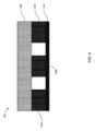
図1は、集電体110上に配設された第1の電極材料120と、第1の電極材料120上に配設された第2の電極材料130とを含む電極100の概略図である。いくつかの実施形態では、第1の電極材料120および/または第2の電極材料130は、固体電極材料、半固体電極材料、高容量材料、およびそれらの組み合わせ(総称して「電極材料」)のうちの少なくとも1つを含み得る。
Figure 1 is a schematic diagram of an
電極100は、カソード、アノードとして、または電気化学デバイスにおける他の任意の方法で使用することができる。いくつかの実施形態では、電極100は、2013年4月29日に提出された「高速度能力を有する半固体電極」と題する米国特許第8,993,159号(「’159特許」)に記載されているような一連の材料および任意の適切な形状因子を含み得、その開示全体が参照により本明細書に組み込まれる。
同様に、集電体110は、カソード集電体、アノード集電体として、または必要に応じて他の任意の目的のために使用されるように構成することができる。考えられる材料、電気化学的適合性特性、形状因子、および集電体110の用途の例は、’159特許にさらに詳細に記載されている。集電体110は、‘159特許に記載されている集電体と実質的に同様であり得るため、本明細書では詳細に説明されていない。
Similarly,
いくつかの実施形態では、電極材料は、活物質、導電性材料、電解質、添加剤、結合剤、および/またはそれらの組み合わせを含み得る。いくつかの実施形態では、活物質は、エネルギーを貯蔵するためにファラデー反応または非ファラデー反応を受け得るイオン貯蔵材料および/または任意の他の化合物もしくはイオン錯体であり得る。活物質はまた、固液懸濁液を含む非レドックス活性相と混合されたレドックス活性固体を含む多相材料、または支持液相と密接に混合された液体イオン貯蔵材料を有するミセルもしくは乳濁液を含む液液多相混合物であり得る。様々な作用イオンを利用するシステムは、Li+、Na+、または他のアルカリイオンが作用イオンであり、さらにCa2+、Mg2+、またはAl3+のようなアルカリ土類作用イオンである水性システムを含み得る。いくつかの実施形態では、負極貯蔵材料および正極貯蔵材料を電気化学的に結合して電気化学セルを形成することができ、負極は、正極よりも低い絶対電位で目的の作用イオンを貯蔵する。セル電圧は、2つのイオン貯蔵電極材料のイオン貯蔵電位の差によっておおよそ決定することができる。 In some embodiments, the electrode material may include active materials, conductive materials, electrolytes, additives, binders, and/or combinations thereof. In some embodiments, the active material may be an ion storage material and/or any other compound or ion complex that may undergo a faradaic or non-faradaic reaction to store energy. The active material may also be a multiphase material that includes a redox active solid mixed with a non-redox active phase, including solid-liquid suspensions, or a liquid-liquid multiphase mixture, including micelles or emulsions with a liquid ion storage material intimately mixed with a supporting liquid phase. Systems utilizing various working ions may include aqueous systems in which Li + , Na + , or other alkali ions are working ions, as well as alkaline earth working ions such as Ca 2+ , Mg 2+ , or Al 3+ . In some embodiments, the negative and positive electrode storage materials may be electrochemically combined to form an electrochemical cell, with the negative electrode storing the working ion of interest at a lower absolute potential than the positive electrode. The cell voltage may be approximately determined by the difference in ion storage potentials of the two ion storage electrode materials.
作用イオンの不溶性貯蔵ホストである負および/または正のイオン貯蔵材料を使用する電気化学セルは、材料の他のすべての構成要素が電解質に実質的に不溶性のままである間、作用イオンを吸収または放出し得る。いくつかの実施形態では、電解質が電気化学的組成物で汚染されないので、これらのセルは特に有利であり得る。さらに、負および/または正のリチウムイオン貯蔵材料を使用するセルは、非水性電気化学組成物を使用する場合に特に有利であり得る。 Electrochemical cells that use negative and/or positive ion storage materials that are insoluble storage hosts for the working ions can absorb or release the working ions while all other components of the material remain substantially insoluble in the electrolyte. In some embodiments, these cells can be particularly advantageous because the electrolyte is not contaminated with the electrochemical composition. Additionally, cells that use negative and/or positive lithium ion storage materials can be particularly advantageous when using non-aqueous electrochemical compositions.
いくつかの実施形態では、イオン貯蔵レドックス組成物は、従来のリチウムイオン電池で作用することが証明された材料を含む。いくつかの実施形態において、正の半固体電気活性材料は、リチウム正電気活性材料を含み、リチウムカチオンは、負極と正極との間を往復し、液体電解質に懸濁された固体のホスト粒子に挿入される。いくつかの実施形態では、リチウムカチオンは、固体の高容量材料の固体マトリックスに挿入することができる。 In some embodiments, the ion-storing redox composition includes materials proven to work in conventional lithium ion batteries. In some embodiments, the positive semi-solid electroactive material includes a lithium positive electroactive material, where the lithium cations shuttle between the negative and positive electrodes and are intercalated into solid host particles suspended in a liquid electrolyte. In some embodiments, the lithium cations can be intercalated into a solid matrix of a solid high capacity material.
いくつかの実施形態では、レドックス活性化合物は、有機または無機であり得、リチウム金属、ナトリウム金属、リチウム金属合金、溶解リチウムをともなうまたはともなわないガリウムおよびインジウム合金、溶融遷移金属塩化物、チオニル塩化物など、または電池の動作条件下で液体になり得るレドックスポリマーおよび有機物を含み得るが、これらに限定されない。そのような液体形態はまた、希釈剤または溶媒である別の非レドックス活性液体で希釈またはそれと混合され得、そのような希釈剤と混合してより低融点の液相を形成することを含む。 In some embodiments, the redox active compounds may be organic or inorganic and may include, but are not limited to, lithium metal, sodium metal, lithium metal alloys, gallium and indium alloys with or without dissolved lithium, molten transition metal chlorides, thionyl chloride, etc., or redox polymers and organics that may become liquid under the operating conditions of the battery. Such liquid forms may also be diluted or mixed with another non-redox active liquid that is a diluent or solvent, including mixing with such a diluent to form a lower melting liquid phase.
いくつかの実施形態では、レドックス活性電極材料は、電池の正極または負極のいずれかに有用な電位で目的の作用イオンを貯蔵する有機レドックス化合物を含み得る。そのような有機レドックス活性貯蔵材料は、ポリアニリンまたはポリアセチレンベースの材料などの「p」ドープ導電性ポリマー、ポリニトロキシドまたは有機ラジカル電極(H.Nishide等、Electrochim.Acta、50,827ー831、(2004)、およびK.Nakahara等、Chem.Phys.Lett.、359,351ー354(2002)に記載されているものなど)、カルボニルベースの有機物、およびLi2C6O6、Li2C8H4O4、Li2C6H4O4などの化合物(例えば、M.Armand等、Nature Materials、DOI:10.1038/nmat2372を参照)および有機硫黄化合物を含むオキソカーボンおよびカルボン酸塩を含む。いくつかの実施形態において、従来の活物質は、コバルト、マンガン、ニッケルーカドミウムーマンガン、リン酸塩、リチウムマンガン酸化物、リチウム鉄リン酸塩、リチウムコバルト酸化物、LiNi0.8Co0.15Al0.05O2、リチウムニッケルマンガン酸化物(LiNi0.5Mn0.5、LiNi0.5Mn1.5など)、リチウムニッケルコバルトマンガン酸化物(LiNi1/3Mn1/3Co1/3など)、リチウム金属、炭素、リチウム挿入炭素、リチウム窒化物、リチウム合金およびリチウム合金形成化合物シリコン、ビスマス、ホウ素、ガリウム、インジウム、亜鉛、スズ、酸化スズ、アンチモン、アルミニウム、酸化チタン、モリブデン、ゲルマニウム、マンガン、ニオブ、バナジウム、タンタル、金、プラチナ、鉄、銅、クロム、ニッケル、コバルト、ジルコニウム、イットリウム、酸化モリブデン、酸化ゲルマニウム、酸化シリコン、炭化シリコン、およびその他の適切な化学物質を含み得る。 In some embodiments, the redox active electrode material may include organic redox compounds that store the working ion of interest at a potential useful for either the positive or negative electrode of the battery. Such organic redox active storage materials include "p" doped conducting polymers such as polyaniline or polyacetylene based materials, polynitroxide or organic radical electrodes (such as those described in H. Nishide et al., Electrochim. Acta, 50, 827-831, (2004), and K. Nakahara et al., Chem. Phys . Lett., 359 , 351-354 (2002)), carbonyl based organics, and compounds such as Li2C6O6 , Li2C8H4O4 , Li2C6H4O4 (see, for example, M. Armand et al . , Nature Materials, DOI: 10.1038 / nmat2372 ), and oxocarbons and carboxylates including organosulfur compounds. In some embodiments , the conventional active materials include cobalt, manganese, nickel-cadmium-manganese , phosphate, lithium manganese oxide, lithium iron phosphate, lithium cobalt oxide, LiNi0.8Co0.15Al0.05O2 . , lithium nickel manganese oxide (LiNi0.5Mn0.5, LiNi0.5Mn1.5, etc.), lithium nickel cobalt manganese oxide (LiNi1/3Mn1/3Co1/3, etc.), lithium metal, carbon, lithium intercalated carbon, lithium nitride, lithium alloys and lithium alloy forming compounds silicon, bismuth, boron, gallium, indium, zinc, tin, tin oxide, antimony, aluminum, titanium oxide, molybdenum, germanium, manganese, niobium, vanadium, tantalum, gold, platinum, iron, copper, chromium, nickel, cobalt, zirconium, yttrium, molybdenum oxide, germanium oxide, silicon oxide, silicon carbide, and other suitable chemicals.
いくつかの実施形態では、電極材料用の導電性材料は、例えば、グラファイト、カーボン粉末、パイロライトカーボン、カーボンブラック、カーボンファイバー、カーボンマイクロファイバー、カーボンナノチューブ(CNT)、単層CNT、多層CNT、「バッキーボール」を含むフラーレンカーボン、グラフェンシートおよび/またはグラフェンシートの集合体、その他の導電性材料、金属(Cu、Al、粉末など)、合金、またはそれらの組み合わせを含み得る。 In some embodiments, conductive materials for the electrode materials may include, for example, graphite, carbon powder, pyrolitic carbon, carbon black, carbon fiber, carbon microfiber, carbon nanotubes (CNTs), single-walled CNTs, multi-walled CNTs, fullerene carbon including "buckyballs", graphene sheets and/or aggregates of graphene sheets, other conductive materials, metals (Cu, Al, powders, etc.), alloys, or combinations thereof.
いくつかの実施形態では、電極材料用の電解質は、例えば、アルコールまたは非プロトン性有機溶媒などの極性溶媒を含み得る非水性液体電解質を含み得る。Liイオン電池電解質の構成要素として多くの有機溶媒、特に、炭酸エチレン、炭酸プロピレン、炭酸ブチレンなどの環状炭酸エステル族およびそれらの塩素化またはフッ素化誘導体、ならびに、炭酸ジメチル、炭酸ジエチル、炭酸エチルメチル、炭酸ジプロピル、炭酸メチルプロピル、炭酸エチルプロピル、炭酸ジブチル、炭酸ブチルメチル、炭酸ブチルエチルおよび炭酸ブチルプロピルなどの非環状ジアルキル炭酸エステル族が提案されている。Liイオン電池電解質溶液の構成要素として提案されている他の溶媒は、γーブチロラクトン、ジメトキシエタン、テトラヒドロフラン、2ーメチルテトラヒドロフラン、1,3ージオキソラン、4ーメチルー1,3ージオキソラン、ジエチルエーテル、スルホラン、メチルスルホラン、アセトニトリル、プロピオノニトリル、酢酸エチル、プロピオン酸メチル、プロピオン酸エチル、炭酸ジメチル、テトラグライムなどを含む。いくつかの実施形態では、これらの非水溶媒は、塩が溶解されてイオン伝導率を提供する多成分混合物として使用することができる。いくつかの実施形態では、リチウム伝導率を提供する塩は、LiClO4、LiPF6、LiBF4、LiFSI、LiAsF6、LiTFSI、LiBETI、LiBOBなどを含み得る。いくつかの実施形態では、電気化学セルは、カソード側の電解質分子をアノード側の電解質分子から分離するように構成された選択透過性膜を含み得る。この選択透過性膜は、2019年1月8日に提出され、その開示は、参照によりその全体が本明細書に組み込まれる「選択透過性膜を含む電気化学セル、その製造システムおよび方法」と題する米国特許出願第16/242,849号(「’849出願」)に記載されているように、複数の電解質(すなわち、アノード側の陽極液およびカソード側の陰極液)の使用を可能にすることができる。 In some embodiments, the electrolyte for the electrode material may include a non-aqueous liquid electrolyte, which may include, for example, a polar solvent such as an alcohol or an aprotic organic solvent. Many organic solvents have been proposed as components of Li-ion battery electrolytes, particularly the cyclic carbonate family and their chlorinated or fluorinated derivatives, such as ethylene carbonate, propylene carbonate, butylene carbonate, and the acyclic dialkyl carbonate family, such as dimethyl carbonate, diethyl carbonate, ethyl methyl carbonate, dipropyl carbonate, methyl propyl carbonate, ethyl propyl carbonate, dibutyl carbonate, butyl methyl carbonate, butyl ethyl carbonate, and butyl propyl carbonate. Other solvents proposed as components of Li-ion battery electrolyte solutions include gamma-butyrolactone, dimethoxyethane, tetrahydrofuran, 2-methyltetrahydrofuran, 1,3-dioxolane, 4-methyl-1,3-dioxolane, diethyl ether, sulfolane, methyl sulfolane, acetonitrile, propiononitrile, ethyl acetate, methyl propionate, ethyl propionate, dimethyl carbonate, tetraglyme, and the like. In some embodiments, these non-aqueous solvents can be used as multi-component mixtures in which salts are dissolved to provide ionic conductivity. In some embodiments, salts providing lithium conductivity can include LiClO 4 , LiPF 6 , LiBF 4 , LiFSI, LiAsF6, LiTFSI, LiBETI, LiBOB, and the like. In some embodiments, the electrochemical cell can include a selectively permeable membrane configured to separate electrolyte molecules on the cathode side from electrolyte molecules on the anode side. This selectively permeable membrane can enable the use of multiple electrolytes (i.e., anolyte on the anode side and catholyte on the cathode side), as described in U.S. Patent Application Serial No. 16/242,849, entitled “Electrochemical Cell Including a Selectively Permeable Membrane, Systems and Methods for Manufacturing Thereof,” filed January 8, 2019 (the “'849 Application”), the disclosure of which is incorporated herein by reference in its entirety.
いくつかの実施形態において、結合剤は、デンプン、カルボキシメチルセルロース(CMC)、ジアセチルセルロース、ヒドロキシプロピルセルロース、エチレングリコール、ポリアクリレート、ポリ(アクリル酸)、ポリテトラフルオロエチレン、ポリイミド、ポリエチレンオキシド、ポリ(フッ化ビニリデン)、ゴム、エチレンープロピレンージエンモノマー(EPDM)、親水性結合剤、ポリフッ化ビニリデン(PVDF)、スチレンブタジエンコポリマー、ポリ(3,4ーエチレンジオキシチオフェン):ポリ(スチレンスルホネート)(PEDOT:PSS)、ポリ(フッ化ビニリデンーcoーヘキサフルオロプロピレン)(PVDFーHFP)、無水マレイン酸グラフトポリフッ化ビニリデン(MPVDF)、スチレンブタジエンゴム(SBR)、SBRとカルボキシメチルセルロースナトリウムの混合物(SBR+CMC)、ポリアクリロニトリル、フッ素化ポリイミド、ポリ(3ーヘキシルチオフェン)ーbーポリ(エチレンオキシド)、ポリ(1ーピレンメチルメタクリレート)(PPy)、ポリ(lーピレンメチルメタクリレートーcoーメタクリル酸)(PPyーMAA)、ポリ(lーピレンメチルメタクリレートーcoートリエチレングリコールメチルエーテル)(PPyE)、ポリアクリル酸およびこのリチウム塩(PAA)、ポリアクリル酸ナトリウム、フッ素化ポリアクリル酸、ポリイミド(PI)、ポリアミドイミド(PAI)、ポリエーテルイミド(PEI)、電極材料に十分な機械的支持を提供するように構成された他の適切なポリマー材料、ならびにそれらの組み合わせを含み得る。いくつかの実施形態では、電極材料は、約0.01重量%~約30重量%、約1重量%~約20重量%、約2重量%~約19重量%、約3重量%~約18重量%、約4重量%~約17重量%、約5重量%~約16重量%、約6重量%~約15重量%、または約5重量%~約20重量%(すべての値および範囲を含む)の結合剤を含み得る。 In some embodiments, the binder is starch, carboxymethyl cellulose (CMC), diacetyl cellulose, hydroxypropyl cellulose, ethylene glycol, polyacrylate, poly(acrylic acid), polytetrafluoroethylene, polyimide, polyethylene oxide, poly(vinylidene fluoride), rubber, ethylene-propylene-diene monomer (EPDM), hydrophilic binder, polyvinylidene fluoride (PVDF), styrene butadiene copolymer, poly(3,4-ethylenedioxythiophene):poly(styrenesulfonate) (PEDOT:PSS), poly(vinylidene fluoride-co-hexafluoropropylene) (PVDF-HFP), maleic anhydride grafted polyvinylidene fluoride (MPVDF), styrene butadiene rubber (SBR), S The polymeric materials may include a mixture of BR and sodium carboxymethylcellulose (SBR+CMC), polyacrylonitrile, fluorinated polyimide, poly(3-hexylthiophene)-b-poly(ethylene oxide), poly(1-pyrene methyl methacrylate) (PPy), poly(1-pyrene methyl methacrylate-co-methacrylic acid) (PPy-MAA), poly(1-pyrene methyl methacrylate-co-triethylene glycol methyl ether) (PPyE), polyacrylic acid and its lithium salt (PAA), sodium polyacrylate, fluorinated polyacrylic acid, polyimide (PI), polyamideimide (PAI), polyetherimide (PEI), other suitable polymeric materials configured to provide sufficient mechanical support to the electrode material, and combinations thereof. In some embodiments, the electrode material may include about 0.01% to about 30% by weight, about 1% to about 20% by weight, about 2% to about 19% by weight, about 3% to about 18% by weight, about 4% to about 17% by weight, about 5% to about 16% by weight, about 6% to about 15% by weight, or about 5% to about 20% by weight (including all values and ranges).
いくつかの実施形態では、電極100の厚さは、少なくとも約30μmであり得る。いくつかの実施形態では、半固体電極の厚さは、少なくとも約100μm、少なくとも約150μm、少なくとも約200μm、少なくとも約250μm、少なくとも約300μm、少なくとも約350μm、少なくとも約400μm、少なくとも約450μm、少なくとも約500μm、少なくとも約600μm、少なくとも約700μm、少なくとも約800μm、少なくとも約900μm、少なくとも約1,000μm、少なくとも約1,500μm、および最大約2,000μm(それらの間のすべての厚さを含む)であり得る。いくつかの実施形態では、第1の電極材料120の厚さは、電極100の全厚さの約50%未満であり得る。いくつかの実施形態では、第1の電極材料120の厚さは、電極100の全厚の約45%未満、約40%未満、約35%未満、約30%未満、約25%未満、約20%未満、約15%未満、約10%未満、約5%未満、または約3%未満であり得る。いくつかの実施形態では、第1の電極材料120の厚さは、約80μm未満、約70μm未満、約60μm未満、約50μm未満、約40μm未満、約30μm未満、約20μm未満、約10μm未満、約5μm未満、約2μm未満、または約1μm未満であり得る。
In some embodiments, the thickness of the
いくつかの実施形態では、第2の電極材料130の厚さは、電極100の全厚さの少なくとも約20%であり得る。いくつかの実施形態では、第2の電極材料130の厚さは、電極100の全厚の少なくとも約50%、少なくとも約60%、少なくとも約70%、少なくとも約80%、少なくとも約90%、少なくとも約95%、少なくとも約97%、少なくとも約98%、または少なくとも約99%であり得る。いくつかの実施形態では、第2の電極材料120の厚さは、少なくとも約30μmであり得る。いくつかの実施形態では、第2の電極材料120の厚さは、少なくとも約50μm、少なくとも約100μm、少なくとも約150μm、少なくとも約200μm、少なくとも約250μm、少なくとも約300μmであり得る。少なくとも約350μm、少なくとも約400μm、少なくとも約450μm、少なくとも約500μm、少なくとも約600μm、少なくとも約700μm、少なくとも約800μm、少なくとも約900μm、少なくとも約1,000μm、少なくとも約1,500μm、および最大約2,000μm(それらの間のすべての厚さを含む)であり得る。
In some embodiments, the thickness of the
いくつかの実施形態では、第1の電極材料120は、従来の固体電極製造プロセスに従って製造された固体電極材料を含み得る。いくつかの実施形態では、固体電極材料は、活物質と、導電性添加剤と、溶媒に溶解または分散された結合剤とを含むスラリーを形成することによって製造することができる。スラリーは、電気化学セル内の電極集電体または他の適切な構造に配設された後、乾燥され(例えば、溶媒を蒸発させることによって)、かつ指定された厚さにカレンダー処理される。固体電極材料の製造はまた、一般に、構築されている電池構造に従って、材料の混合、鋳造、カレンダー処理、乾燥、切断、および加工(曲げ、圧延など)を含み得る。電極材料が乾燥されてカレンダー処理にかけられると、電極材料を電解質で(例えば、圧力下で)湿らせることができる。
In some embodiments, the
いくつかの実施形態では、第1の電極材料120は、蒸着プロセスによって製造された固体電極材料を含む得、蒸着プロセスは、蒸着、電気ビーム蒸着、電気化学蒸着、ゾルゲル、スパッタリング、および物理スプレー法を含む。
In some embodiments, the
いくつかの実施形態では、第2の電極材料130は、第1の電極材料120上に分散された純粋な導電剤を含み得る。電解質として第1の電極材料120上に導電性スラリーを(活物質なしで)コーティングすることは、従来のセル製造プロセスにおける電解質放出のための代替方法として役立つ。導電剤は、特に体積膨張材料を用いて、サイクル中に第1の電極材料120に流れ込み、空隙を埋めることができる。言い換えれば、導電剤の使用は、電極の電子伝導性を維持するのを助けることができ、それにより、第1の電極材料120のサイクル安定性を改善することができる。
In some embodiments, the
いくつかの実施形態では、第2の電極材料130は、半固体電極材料を含み得る。いくつかの実施形態では、本明細書に記載の半固体電極材料は、(i)半固体電極の低減された屈曲度およびより高い電子伝導率に起因して、固体電極材料より厚く(例えば、250μm~最大2,000μm、またはそれより厚く)、(ii)従来の電極材料よりも高い活物質の負荷で、(iii)より少ない装置を使用する単純化された製造プロセスによって、作ることができる。これらの比較的厚い半固体電極は、活性成分に対する不活性成分の体積、質量、およびコストの寄与を減少させ、それにより、半固体電極材料を含む電極の商業的訴求力を高める。いくつかの実施形態では、第2の電極材料130は、乾燥工程がなくても第1の電極材料120上に配設することができる。乾燥工程を省くことで、処理時間および製造コストを削減できる可能性がある。いくつかの実施形態では、第2の電極材料130をセパレータ(図示せず)上に配設することができ、次に、第2の電極材料130をともなうセパレータを、集電体110上に配設された第1の電極材料120と組み合わせることができる。いくつかの実施形態では、第2の電極材料130は、結合剤を含み得る。いくつかの実施形態では、第2の電極材料130は、実質的に結合剤を含んでいなくてもよい。
In some embodiments, the
いくつかの実施形態では、本明細書に記載の半固体電極材料は、結合剤なしであり得る。代わりに、半固体電極材料において従来の電極の結合剤が通常占めていた体積は、現在、1)屈曲度を減少させ、イオン拡散に利用できる総塩を増加させる効果があり、それによって、従来の厚い電極を高速で使用した場合に典型的な塩類の枯渇効果に対抗する電解質、2)電池の充電容量を増加させる効果を有する活物質、または3)電極の電子伝導率を増加させる効果を有し、それによって、従来の厚い電極の高い内部インピーダンスに対抗する導電性添加剤によって占められている。本明細書に記載の半固体電極の減少した屈曲度およびより高い電子伝導率は、半固体電極から形成された電気化学セルの優れた速度能力および電荷容量をもたらす。 In some embodiments, the semi-solid electrode materials described herein can be binder-free. Instead, the volume typically occupied by the binder in conventional electrodes in the semi-solid electrode materials is now occupied by 1) an electrolyte, which has the effect of reducing tortuosity and increasing the total salt available for ion diffusion, thereby countering the salt depletion effect typical of conventional thick electrodes at high rates; 2) an active material, which has the effect of increasing the charge capacity of the battery; or 3) a conductive additive, which has the effect of increasing the electronic conductivity of the electrode, thereby countering the high internal impedance of conventional thick electrodes. The reduced tortuosity and higher electronic conductivity of the semi-solid electrodes described herein result in superior rate capability and charge capacity of electrochemical cells formed from the semi-solid electrodes.
本明細書に記載の半固体電極材料は、従来の電極材料よりも実質的に厚くすることができるので、不活性物質に対する活物質の比率をはるかに高くすることができる。いくつかの実施形態では、この増大した活性対不活性材料比は、本明細書に記載の半固体電極材料を含む電池の全体的な充電容量およびエネルギー密度を増加させることができる。 The semi-solid electrode materials described herein can be made substantially thicker than conventional electrode materials, allowing for a much higher ratio of active material to inactive material. In some embodiments, this increased active-to-inactive material ratio can increase the overall charge capacity and energy density of batteries including the semi-solid electrode materials described herein.
本明細書に記載されるように、固体電極材料は、典型的には密度が高く(より低い気孔率を有する)、一方、半固体電極材料は、典型的にはより密度が低い(より高い気孔率を有する)。特定の理論に束縛されることを望まないが、固体電極材料のより低い気孔率は、電極の厚さ全体にわたるイオンの屈曲度の増大のために、利用可能な活物質へのイオン伝導のより低い確率をもたらす可能性がある。いくつかの実施形態では、第1の電極材料120は、固体電極材料を含み得、第2の電極材料130は、電極の厚さ全体にわたる組成勾配が気孔率の変化を含むように、半固体電極材料を含み得る。特定の理論に束縛されることを望まないが、電極100の厚さ全体にわたる気孔率勾配を作成することにより、電極100の総理論的エネルギー密度は、従来の電極材料の使用のためにより高く、イオンに対する従来の活性物質の接近性は、半固体電極材料全体にわたる高いイオン流動のために、高いままである。
As described herein, solid electrode materials are typically dense (have lower porosity), while semi-solid electrode materials are typically less dense (have higher porosity). Without wishing to be bound by any particular theory, the lower porosity of the solid electrode material may result in a lower probability of ion conduction to the available active material due to increased tortuosity of the ions throughout the thickness of the electrode. In some embodiments, the
いくつかの実施形態では、第1の電極材料120は固体電極材料を含むと説明し、第2の電極材料130は半固体電極材料を含むと説明したが、他の構成および化学的性質が可能である。例えば、いくつかの実施形態では、第1の電極材料120は、第1の組成物を有する半固体電極材料を含み得、第2の電極材料130は、第2の組成物を有する半固体電極材料を含み得る。いくつかの実施形態では、第1の電極材料120は、第1の気孔率を有する半固体電極材料を含み得、第2の電極材料130は、第1の気孔率よりも大きい第2の気孔率を有する半固体電極材料を含み得る。いくつかの実施形態では、第1の電極材料120は、第1のイオン貯蔵容量を有する半固体電極材料を含み得、第2の電極材料130は、第1のイオン貯蔵容量よりも小さい第2のイオン貯蔵容量を有する半固体電極材料を含み得る。いくつかの実施形態では、第1の電極材料120は、第1のイオン伝導率を有する半固体電極材料を含むことができ、第2の電極材料130は、第1のイオン伝導率よりも大きい第2のイオン伝導率を有する半固体電極材料を含み得る。
In some embodiments, the
いくつかの実施形態では、第1の電極材料120は、第1の気孔率を有し得、第2の電極材料130は、第1の気孔率よりも小さい第2の気孔率を有し得る。いくつかの実施形態では、第2の気孔率は、第1の気孔率よりも大きくすることができる。いくつかの実施形態では、第2の気孔率は、第1の気孔率と実質的に等しくすることができる。
In some embodiments, the
いくつかの実施形態では、第1の気孔率は、約3%未満または約5%未満であり得る。いくつかの実施形態では、第1の気孔率は、約20%~約25%、約25%~約30%、約30%~約35%、約35%~約40%、約40%~約45%、約45%から約50%、約50%から約55%、または約55%から約60%であり得る。 In some embodiments, the first porosity can be less than about 3% or less than about 5%. In some embodiments, the first porosity can be about 20% to about 25%, about 25% to about 30%, about 30% to about 35%, about 35% to about 40%, about 40% to about 45%, about 45% to about 50%, about 50% to about 55%, or about 55% to about 60%.
いくつかの実施形態では、第2の気孔率は、約20%~約25%、約25%~約30%、約30%~約35%、約35%~約40%、約40%~約45%、約45%~約50%、約50%~約55%、または約55%~約60%であり得る。 In some embodiments, the second porosity can be about 20% to about 25%, about 25% to about 30%, about 30% to about 35%, about 35% to about 40%, about 40% to about 45%, about 45% to about 50%, about 50% to about 55%, or about 55% to about 60%.
いくつかの実施形態では、第1の電極材料120は、第1の表面積を有し得、第2の電極材料130は、第1の表面積よりも大きい第2の表面積を有し得る。いくつかの実施形態では、第2の表面積は、第1の面積よりも小さくすることができる。いくつかの実施形態では、第2の表面積は、第1の表面積と実質的に等しくすることができる。
In some embodiments, the
いくつかの実施形態では、第1の電極材料120は、約1m2/g未満の表面積をともなう活物質を含み得る。いくつかの実施形態では、第1の電極材料120は、約1m2/g~約2m2/g、約2m2/gから約3m2/g、約3m2/g~約4m2/g、約4m2/g~約5m2/g、または約5m2/gより大きい表面積をともなう活物質を含み得る。
In some embodiments, the
いくつかの実施形態では、第2の電極材料130は、約1m2/g未満の表面積をともなう活物質を含み得る。いくつかの実施形態では、第2の電極材料130は、約1m2/g~約2m2/g、約2m2/gから約3m2/g、約3m2/g~約4m2/g、約4m2/g~約5m2/g、または約5m2/gより大きい表面積をともなう活物質を含み得る。
In some embodiments, the
いくつかの実施形態では、電気化学セルの動作中、イオンは、第1の速度で第2の電極材料130を通って、第1の速度よりも小さい第2の速度で第1の電極材料120へ往復させ得る。いくつかの実施形態では、第1の電極材料120は、第1のイオン貯蔵容量を有し得、第2の電極材料130は、第1のイオン貯蔵容量よりも小さい第2のイオン貯蔵容量を有し得る。いくつかの実施形態では、完成電極は、集電体110、第1の電極材料120、および第3の電極材料130の厚さの合計に実質的に等しい厚さを有し得る。いくつかの実施形態では、完成した組成勾配電極の厚さは、第1の電極材料120のみまたは第2の電極材料130のみのいずれかから形成され、かつ完成した組成勾配電極と同じ厚さを有する電極よりも大きい電力密度を有し得る。
In some embodiments, during operation of the electrochemical cell, ions may be shuttled through the
いくつかの実施形態では、第1の電極材料120は、シリコンベース(Si、SiO、Si合金)および/またはスズベース(Sn、SnO、Sn合金)などの帯電において、第2の電極材料130よりも高い濃度の高膨張活物質を含み得る。
In some embodiments, the
より高膨張の活物質は、サイクル中の膨張ー圧縮力のために、充電および放電サイクルの後に小さな粒子に移行する可能性がある。これらの力は、サイクル中の電子ネットワークを減少させる傾向があり、集電体の近くのより高膨張の材料は、電子経路を確保することができる。いくつかの実施形態では、第2の電極材料130として半固体電極を有することは、これらの膨張力を吸収する傾向がある。いくつかの実施形態では、第1の電極材料120において高膨張性活物質の高い気孔率を有することにより、第2層においてより高い電子伝導率のネットワークおよびより低い膨張率の活物質を有する半販売電極が多孔質領域に移動し、それによって電子ネットワークを維持することができる。
The higher expansion active material may migrate to smaller particles after charge and discharge cycles due to expansion-compression forces during cycling. These forces tend to reduce the electronic network during cycling, and the higher expansion material near the current collector can ensure the electronic pathway. In some embodiments, having a semi-solid electrode as the
いくつかの実施形態では、組成勾配を有する完成電極100(例えば、第1の電極材料120と第2の電極材料130とを含む)のエネルギー密度は、約0.2MJ/L、約0.25MJ/L、約0.3MJ/L、約0.35MJ/L、約0.4MJ/L、約0.45MJ/L、約0.5MJ/L、約0.55MJ/L、約0.6J/L、約0.65MJ/L、約0.7MJ/L、約0.75MJ/L、約0.8MJ/L、約0.85MJ/L、約0.9MJ/L、約0.95MJ/L、約1.0MJ/L、約1.05MJ/L、約1.1MJ/L、約1.15MJ/L、約1.2MJ/L、約1.25MJ/L、約1.3MJ/L、約1.35MJ/L、約1.4MJ/L、約1.45MJ/L、約1.5MJ/L、約1.55MJ/L、約1.6MJ/L、約1.65MJ/L、約1.7MJ/L、約1.75MJ/L、約1.8MJ/L、約1.85MJ/L、約1.9MJ/L、約1.95MJ/L、約2.0MJ/L、約2.05MJ/L、約2.1MJ/L、約2.15MJ/L、約2.2MJ/L、約2.25MJ/L、約2.3MJ/L、約2.35MJ/L、約2.4MJ/L、約2.45MJ/L、約2.5MJ/L、約2.55MJ/L、約2.6MJ/L、約2.65MJ/L、約2.7MJ/L、約2.75MJ/L、約2.8MJ/L、約2.85MJ/L、約2.9MJ/L、約2.95MJ/L、約3.0MJ/L、約3.5MJ/L、約4.0MJ/L、約4.5MJ/L、または約5.0MJ/L(これらの間のすべての値および範囲を含む)より大きくすることができる。 In some embodiments, the energy density of the finished electrode 100 having a composition gradient (e.g., including the first electrode material 120 and the second electrode material 130) is about 0.2 MJ/L, about 0.25 MJ/L, about 0.3 MJ/L, about 0.35 MJ/L, about 0.4 MJ/L, about 0.45 MJ/L, about 0.5 MJ/L, about 0.55 MJ/L, about 0.6 MJ/L, about 0.65 MJ/L, about 0.7 MJ/L, or about 0.8 MJ/L. , about 0.75MJ/L, about 0.8MJ/L, about 0.85MJ/L, about 0.9MJ/L, about 0.95MJ/L, about 1.0MJ/L, about 1.05MJ/L, about 1.1MJ/L, about 1.15MJ/L, about 1.2MJ/L, about 1.25MJ/L, about 1.3MJ/L, about 1.35M J/L, approximately 1.4MJ/L, approximately 1.45MJ/L, approximately 1.5MJ/L, approximately 1.55MJ/L, approximately 1.6MJ/L , about 1.65MJ/L, about 1.7MJ/L, about 1.75MJ/L, about 1.8MJ/L, about 1.85MJ/L, about 1.9MJ/L, about 1.95MJ/L, about 2.0MJ/L, about 2.05MJ/L, about 2.1MJ/L, about 2.15MJ/L, about 2.2MJ/L, about 2.25M J/L, approximately 2.3MJ/L, approximately 2.35MJ/L, approximately 2.4MJ/L, approximately 2.45MJ/L, approximately 2.5MJ/ MJ/L, about 2.55 MJ/L, about 2.6 MJ/L, about 2.65 MJ/L, about 2.7 MJ/L, about 2.75 MJ/L, about 2.8 MJ/L, about 2.85 MJ/L, about 2.9 MJ/L, about 2.95 MJ/L, about 3.0 MJ/L, about 3.5 MJ/L, about 4.0 MJ/L, about 4.5 MJ/L, or about 5.0 MJ/L (including all values and ranges therebetween).
いくつかの実施形態では、第1の電極材料120のエネルギー密度は、約0.2MJ/L、約0.25MJ/L、約0.3MJ/L、約0.35MJ/L、約0.4MJ/L、約0.45MJ/L、約0.5MJ/L、約0.55MJ/L、約0.6J/L、約0.65MJ/L、約0.7MJ/L、約0.75MJ/L、約0.8MJ/L、約0.85MJ/L、約0.9MJ/L、約0.95MJ/L、約1.0MJ/L、約1.05MJ/L、約1.1MJ/L、約1.15MJ/L、約1.2MJ/L、約1.25MJ/L、約1.3MJ/L、約1.35MJ/L、約1.4MJ/L、約1.45MJ/L、約1.5MJ/L、約1.55MJ/L、約1.6MJ/L、約1.65MJ/L、約1.7MJ/L、約1.75MJ/L、約1.8MJ/L、約1.85MJ/L、約1.9MJ/L、約1.95MJ/L、約2.0MJ/L、約2.05MJ/L、約2.1MJ/L、約2.15MJ/L、約2.2MJ/L、約2.25MJ/L、約2.3MJ/L、約2.35MJ/L、約2.4MJ/L、約2.45MJ/L、約2.5MJ/L、約2.55MJ/L、約2.6MJ/L、約2.65MJ/L、約2.7MJ/L、約2.75MJ/L、約2.8MJ/L、約2.85MJ/L、約2.9MJ/L、約2.95MJ/L、約3.0MJ/L、約3.5MJ/L、約4.0MJ/L、約4.5MJ/L、または約5.0MJ/L(これらの間のすべての値および範囲を含む)より大きくすることができる。 In some embodiments, the energy density of the first electrode material 120 is about 0.2 MJ/L, about 0.25 MJ/L, about 0.3 MJ/L, about 0.35 MJ/L, about 0.4 MJ/L, about 0.45 MJ/L, about 0.5 MJ/L, about 0.55 MJ/L, about 0.6 MJ/L, about 0.65 MJ/L, about 0.7 MJ/L, about 0.75 MJ/L, about 0.8 MJ/L, about 0.85 MJ /L, about 0.9MJ/L, about 0.95MJ/L, about 1.0MJ/L, about 1.05MJ/L, about 1.1MJ/L, about 1.15MJ/L, about 1.2MJ/L, about 1.25MJ/L, about 1.3MJ/L, about 1.35MJ/L, about 1.4MJ/L, about 1.45MJ/L, about 1.5 MJ/L, approximately 1.55MJ/L, approximately 1.6MJ/L, approximately 1.65MJ/L, approximately 1.7MJ/ L, about 1.75 MJ/L, about 1.8 MJ/L, about 1.85 MJ/L, about 1.9 MJ/L, about 1.95 MJ/L, about 2.0 MJ/L, about 2.05 MJ/L, about 2.1 MJ/L, about 2.15 MJ/L, about 2.2 MJ/L, about 2.25 MJ/L, about 2.3 MJ/L, about 2.35 MJ/L, approximately 2.4MJ/L, approximately 2.45MJ/L, approximately 2.5MJ/L, approximately 2.55MJ /L, about 2.6 MJ/L, about 2.65 MJ/L, about 2.7 MJ/L, about 2.75 MJ/L, about 2.8 MJ/L, about 2.85 MJ/L, about 2.9 MJ/L, about 2.95 MJ/L, about 3.0 MJ/L, about 3.5 MJ/L, about 4.0 MJ/L, about 4.5 MJ/L, or about 5.0 MJ/L (including all values and ranges therebetween).
いくつかの実施形態では、第2の電極材料130のエネルギー密度は、約0.2MJ/L、約0.25MJ/L、約0.3MJ/L、約0.35MJ/L、約0.4MJ/L、約0.45MJ/L、約0.5MJ/L、約0.55MJ/L、約0.6J/L、約0.65MJ/L、約0.7MJ/L、約0.75MJ/L、約0.8MJ/L、約0.85MJ/L、約0.9MJ/L、約0.95MJ/L、約1.0MJ/L、約1.05MJ/L、約1.1MJ/L、約1.15MJ/L、約1.2MJ/L、約1.25MJ/L、約1.3MJ/L、約1.35MJ/L、約1.4MJ/L、約1.45MJ/L、約1.5MJ/L、約1.55MJ/L、約1.6MJ/L、約1.65MJ/L、約1.7MJ/L、約1.75MJ/L、約1.8MJ/L、約1.85MJ/L、約1.9MJ/L、約1.95MJ/L、約2.0MJ/L、約2.05MJ/L、約2.1MJ/L、約2.15MJ/L、約2.2MJ/L、約2.25MJ/L、約2.3MJ/L、約2.35MJ/L、約2.4MJ/L、約2.45MJ/L、約2.5MJ/L、約2.55MJ/L、約2.6MJ/L、約2.65MJ/L、約2.7MJ/L、約2.75MJ/L、約2.8MJ/L、約2.85MJ/L、約2.9MJ/L、約2.95MJ/L、約3.0MJ/L、約3.5MJ/L、約4.0MJ/L、約4.5MJ/L、または約5.0MJ/L(これらの間のすべての値および範囲を含む)より大きくすることができる。 In some embodiments, the energy density of the second electrode material 130 is about 0.2 MJ/L, about 0.25 MJ/L, about 0.3 MJ/L, about 0.35 MJ/L, about 0.4 MJ/L, about 0.45 MJ/L, about 0.5 MJ/L, about 0.55 MJ/L, about 0.6 MJ/L, about 0.65 MJ/L, about 0.7 MJ/L, about 0.75 MJ/L, about 0.8 MJ/L, about 0.85 MJ /L, about 0.9MJ/L, about 0.95MJ/L, about 1.0MJ/L, about 1.05MJ/L, about 1.1MJ/L, about 1.15MJ/L, about 1.2MJ/L, about 1.25MJ/L, about 1.3MJ/L, about 1.35MJ/L, about 1.4MJ/L, about 1.45MJ/L, about 1.5 MJ/L, approximately 1.55MJ/L, approximately 1.6MJ/L, approximately 1.65MJ/L, approximately 1.7MJ/ L, about 1.75 MJ/L, about 1.8 MJ/L, about 1.85 MJ/L, about 1.9 MJ/L, about 1.95 MJ/L, about 2.0 MJ/L, about 2.05 MJ/L, about 2.1 MJ/L, about 2.15 MJ/L, about 2.2 MJ/L, about 2.25 MJ/L, about 2.3 MJ/L, about 2.35 MJ/L, approximately 2.4MJ/L, approximately 2.45MJ/L, approximately 2.5MJ/L, approximately 2.55MJ /L, about 2.6 MJ/L, about 2.65 MJ/L, about 2.7 MJ/L, about 2.75 MJ/L, about 2.8 MJ/L, about 2.85 MJ/L, about 2.9 MJ/L, about 2.95 MJ/L, about 3.0 MJ/L, about 3.5 MJ/L, about 4.0 MJ/L, about 4.5 MJ/L, or about 5.0 MJ/L (including all values and ranges therebetween).
いくつかの実施形態では、組成勾配を有する完成電極100(例えば、第1の電極材料120と第2の電極材料130とを含む)の比エネルギーは、約0.2MJ/kg、約0.25MJ/kg、約0.3MJ/kg、約0.35MJ/kg、約0.4MJ/kg、約0.45MJ/kg、約0.5MJ/kg、約0.55MJ/kg、約0.6J/kg、約0.65MJ/kg、約0.7MJ/kg、約0.75MJ/kg、約0.8MJ/kg、約0.85MJ/kg、約0.9MJ/kg、約0.95MJ/kg、約1.0MJ/kg、約1.05MJ/kg、約1.1MJ/kg、約1.15MJ/kg、約1.2MJ/kg、約1.25MJ/kg、約1.3MJ/kg、約1.35MJ/kg、約1.4MJ/kg、約1.45MJ/kg、または約1.5MJ/kg(これらの間のすべての値および範囲を含む)より大きくすることができる。
In some embodiments, the specific energy of the
いくつかの実施形態では、第1の電極材料120の比エネルギーは、約0.2MJ/kg、約0.25MJ/kg、約0.3MJ/kg、約0.35MJ/kg、約0.4MJ/kg、約0.45MJ/kg、約0.5MJ/kg、約0.55MJ/kg、約0.6J/kg、約0.65MJ/kg、約0.7MJ/kg、約0.75MJ/kg、約0.8MJ/kg、約0.85MJ/kg、約0.9MJ/kg、約0.95MJ/kg、約1.0MJ/kg、約1.05MJ/kg、約1.1MJ/kg、約1.15MJ/kg、約1.2MJ/kg、約1.25MJ/kg、約1.3MJ/kg、約1.35MJ/kg、約1.4MJ/kg、約1.45MJ/kg、または約1.5MJ/kg(これらの間のすべての値と範囲を含む)より大きくすることができる。 In some embodiments, the specific energy of the first electrode material 120 is about 0.2 MJ/kg, about 0.25 MJ/kg, about 0.3 MJ/kg, about 0.35 MJ/kg, about 0.4 MJ/kg, about 0.45 MJ/kg, about 0.5 MJ/kg, about 0.55 MJ/kg, about 0.6 J/kg, about 0.65 MJ/kg, about 0.7 MJ/kg, about 0.75 MJ/kg, about 0.8 MJ/kg, about 0.85 MJ/kg, about 0.9 MJ/kg, about 10 MJ/kg, about 11 MJ/kg, about 12 MJ/kg, about 13 MJ/kg, about 14 MJ/kg, about 15 MJ/kg, about 16 MJ/kg, about 17 MJ/kg, about 18 MJ/kg, about 19 MJ/kg, about 20 MJ/kg, about 21 MJ/kg, about 22 MJ/kg, about 23 MJ/kg, about 24 MJ/kg, about 25 MJ/kg, about 26 MJ/kg, about 27 MJ/kg, about 28 MJ/kg, about 29 MJ/kg, about 30 MJ/kg, about 31 MJ/kg, about 32 MJ/kg, about 33 MJ/kg, about 34 MJ/kg, about 35 MJ/kg, about 36 MJ/kg, about 37 MJ/kg, about 38 MJ/kg, about 39 MJ/kg, about 40 MJ/kg, about 41 MJ/kg, about 42 MJ/kg, about 43 MJ/kg, about 44 MJ/kg, about 45 MJ/kg, about 46 MJ/kg, about 47 M kg, about 0.9 MJ/kg, about 0.95 MJ/kg, about 1.0 MJ/kg, about 1.05 MJ/kg, about 1.1 MJ/kg, about 1.15 MJ/kg, about 1.2 MJ/kg, about 1.25 MJ/kg, about 1.3 MJ/kg, about 1.35 MJ/kg, about 1.4 MJ/kg, about 1.45 MJ/kg, or about 1.5 MJ/kg (including all values and ranges therebetween).
いくつかの実施形態では、第2の電極材料130の比エネルギーは、約0.2MJ/kg、約0.25MJ/kg、約0.3MJ/kg、約0.35MJ/kg、約0.4MJ/kg、約0.45MJ/kg、約0.5MJ/kg、約0.55MJ/kg、約0.6J/kg、約0.65MJ/kg、約0.7MJ/kg、約0.75MJ/kg、約0.8MJ/kg、約0.85MJ/kg、約0.9MJ/kg、約0.95MJ/kg、約1.0MJ/kg、約1.05MJ/kg、約1.1MJ/kg、約1.15MJ/kg、約1.2MJ/kg、約1.25MJ/kg、約1.3MJ/kg、約1.35MJ/kg、約1.4MJ/kg、約1.45MJ/kg、または約1.5MJ/kg(これらの間のすべての値と範囲を含む)より大きくすることができる。 In some embodiments, the specific energy of the second electrode material 130 is about 0.2 MJ/kg, about 0.25 MJ/kg, about 0.3 MJ/kg, about 0.35 MJ/kg, about 0.4 MJ/kg, about 0.45 MJ/kg, about 0.5 MJ/kg, about 0.55 MJ/kg, about 0.6 J/kg, about 0.65 MJ/kg, about 0.7 MJ/kg, about 0.75 MJ/kg, about 0.8 MJ/kg, about 0.85 MJ/kg, about 0.9 MJ/kg, about 10 MJ/kg, about 11 MJ/kg, about 12 MJ/kg, about 13 MJ/kg, about 14 MJ/kg, about 15 MJ/kg, about 16 MJ/kg, about 17 MJ/kg, about 18 MJ/kg, about 19 MJ/kg, about 20 MJ/kg, about 21 MJ/kg, about 22 MJ/kg, about 23 MJ/kg, about 24 MJ/kg, about 25 MJ/kg, about 26 MJ/kg, about 27 MJ/kg, about 28 MJ/kg, about 29 MJ/kg, about 30 MJ/kg, about 31 MJ/kg, about 32 MJ/kg, about 33 MJ/kg, about 34 MJ/kg, about 35 MJ/kg, about 36 MJ/kg, about 37 MJ/kg, about 38 MJ/kg, about 39 MJ/kg, about 40 MJ/kg, about 41 MJ/kg, about 42 MJ/kg, about 43 MJ/kg, about 44 MJ/kg, about 45 MJ/kg, about 46 MJ/kg, about 47 M kg, about 0.9 MJ/kg, about 0.95 MJ/kg, about 1.0 MJ/kg, about 1.05 MJ/kg, about 1.1 MJ/kg, about 1.15 MJ/kg, about 1.2 MJ/kg, about 1.25 MJ/kg, about 1.3 MJ/kg, about 1.35 MJ/kg, about 1.4 MJ/kg, about 1.45 MJ/kg, or about 1.5 MJ/kg (including all values and ranges therebetween).
いくつかの実施形態では、第1の電極材料120は、高容量アノード材料を、約10体積%、約20体積%、約30体積%、約40体積%、約50体積%、約60体積%、約70体積%、約80体積%、約90体積%、または約100体積%を含み得る。いくつかの実施形態では、第2の電極材料130は、炭素、グラファイト、または結合剤の有無にかかわらず他の活物質と組み合わされた高容量アノード材料を含み得る。いくつかの実施形態では、第2の電極材料130は、高容量アノード材料を、約60体積%未満、約55体積%未満、約50体積%未満、約45体積%未満、約40体積%未満、約35体積%未満、約30%体積%未満の、約25体積%未満、約20体積%未満、約15体積%未満、約10体積%未満、または約5体積%未満含み得る。いくつかの実施形態では、第2の電極材料130は、高容量材料を実質的に含んでいなくてもよい。
In some embodiments, the
上記のように、電極100は、2つの異なるアノード材料の層を含む。いくつかの実施形態では、電極100は、代替的に、2つ以上の異なるカソード材料の層を含み得る。いくつかの実施形態では、第1の電極材料120および/または第2の電極材料130は、リチウムイオン電池のカソードとして使用することができる任意の材料を含み得る。電気化学セルで使用することができるカソード材料の例は、上記の参照により組み込まれた’159特許に記載されている。
As noted above,
典型的には、リチウムイオン電池で使用されるカソードにおける集電体110は、導電性炭素でコーティングされたアルミニウムから作られている。導電性炭素コーティングは、導電性を改善し、かつ集電体110の機械的強度を増加させることができ、それにより、集電体110の亀裂の可能性を低減する。いくつかの実施形態では、第1の電極材料120は、導電性炭素層の代わりに裸アルミニウム集電体上に配設することができる。いくつかの実施形態では、カソード内の第1の電極材料120は、上記のように、アノード内と同じ方法を介して製造および/または堆積することができる。いくつかの実施形態では、カソードの第1の電極材料120は、上記のように、アノードの第1の電極材料120の厚さと同じまたは同様の厚さを有し得る。いくつかの実施形態では、カソード内の第2の電極材料130は、半固体カソードであり得、上記のように、アノード中と同じ方法を介して堆積することができる。いくつかの実施形態では、カソードの第2の電極材料130は、上記のように、アノードの第2の電極材料130の厚さと同様の厚さを有し得る。
Typically, the
いくつかの実施形態では、第2の電極材料130内の高容量アノード材料の体積パーセントは、第1の電極材料120内の高容量アノード材料の体積パーセントよりも約10~80%少なくてもよい。
In some embodiments, the volume percentage of the high capacity anode material in the
いくつかの実施形態では、組成勾配を有する完成電極100(例えば、第1の電極材料120と第2の電極材料130とを含む)のサイクル寿命は、約200回の充電/放電サイクル超、約250サイクル超、約300サイクル超、約350サイクル超、約400サイクル超、約450サイクル超、約500サイクル超、約550サイクル超、約600サイクル超、約650サイクル超、約700サイクル超、約750サイクル超、約800サイクル超、約850サイクル超、約900サイクル超、約950サイクル超、約1,000サイクル超、約1,050サイクル超、約1,100サイクル超、約1,250サイクル超、約1,300サイクル超、約1,350サイクル超、約1,400サイクル超、約1,450サイクル超、約1,500サイクル超、約1,550サイクル超、約1,600サイクル超、約1,650サイクル超、約1,700サイクル超、約1,750サイクル超、約1,800サイクル超、約1,850サイクル超、約1,900サイクル超、約1,950サイクル超、約2,000サイクル超、約2,500サイクル超、約3,000サイクル超、約5,000サイクル超、または約10,000サイクル超であり得る。 In some embodiments, the cycle life of the finished electrode 100 having a composition gradient (e.g., including a first electrode material 120 and a second electrode material 130) is greater than about 200 charge/discharge cycles, greater than about 250 cycles, greater than about 300 cycles, greater than about 350 cycles, greater than about 400 cycles, greater than about 450 cycles, greater than about 500 cycles, greater than about 550 cycles, greater than about 600 cycles, greater than about 650 cycles, greater than about 700 cycles, greater than about 750 cycles, greater than about 800 cycles, greater than about 850 cycles, greater than about 900 cycles, greater than about 950 cycles, greater than about 1,000 cycles, greater than about 1,050 cycles, greater than about 1 , 100 cycles, more than about 1,250 cycles, more than about 1,300 cycles, more than about 1,350 cycles, more than about 1,400 cycles, more than about 1,450 cycles, more than about 1,500 cycles, more than about 1,550 cycles, more than about 1,600 cycles, more than about 1,650 cycles, more than about 1,700 cycles, more than about 1,750 cycles, more than about 1,800 cycles, more than about 1,850 cycles, more than about 1,900 cycles, more than about 1,950 cycles, more than about 2,000 cycles, more than about 2,500 cycles, more than about 3,000 cycles, more than about 5,000 cycles, or more than about 10,000 cycles.
いくつかの実施形態では、組成勾配を有する完成電極100を含む(例えば、第1の電極材料120と第2の電極材料130とを含む)電気化学セルの充電速度は、1Cの速度で電極材料100gあたり約5時間未満、約4.5時間未満、約3時間未満、約3時間未満、約2.5時間未満、約2時間未満、約1.5時間未満、または約1時間未満(これらの間のすべての値および範囲を含む)であり得る。いくつかの実施形態では、半固体電極の第2の電極材料130と従来の(すなわち、「乾いた」)第1の電極材料120とを有することにより、通常、従来の電池製造プロセスの最後のステップである電解質充填プロセスを回避することができる。これにより、第2の電極材料130に存在する電解質が第1の電極材料120を飽和させることを可能にすることで、第1の電極材料120におけるより高い負荷につながる可能性もある。
In some embodiments, the charge rate of an electrochemical cell including a
リチオ化前
多くの電極、例えば、リチウムイオン電極、特にアノードは、電池形成段階(すなわち、電極を含む電気化学セルの充電および放電を含む最初のサイクルステップ)で不可逆的な容量損失を被る可能性がある。アノードによるカソード活物質からのリチウムイオンの消費により、不可逆的な容量損失が発生する可能性があり、アノードは、これらのリチウムイオンを固体電解質界面(SEI)層の形成に使用する。この消費されたリチウムの量は、その後の電荷貯蔵での使用に利用できなくなるので、望ましくない不可逆的な容量損失を表す。さらに、この不可逆的な容量損失は、リチウムイオンがアノード材料に不可逆的にトラップされるため、アノードの体積膨張をともなう可能性がある。この体積膨張の問題は、半固体アノード配合物内の高容量アノード材料(例えば、シリコンまたはスズ)を含む半固体アノードで悪化する。なぜなら、グラファイトなどの従来の材料と比較して、高容量アノード材料は、より大量のリチウムを取り込むことができる(およびより高エネルギーのセル設計を可能にする)からである。例えば、グラファイトは6個の炭素原子ごとに約1個のリチウム原子を取り込むことができるが、シリコンは理論的にはすべてのシリコン原子ごとに約4.4個のリチウム原子を取り込むことができる。
Many electrodes, e.g., lithium-ion electrodes, especially anodes, can suffer from irreversible capacity loss during the battery formation stage (i.e., the first cycling step involving charging and discharging an electrochemical cell containing the electrode). Irreversible capacity loss can occur due to the consumption of lithium ions from the cathode active material by the anode, which uses these lithium ions to form a solid electrolyte interface (SEI) layer. This amount of consumed lithium represents an undesirable irreversible capacity loss, as it is no longer available for use in subsequent charge storage. Furthermore, this irreversible capacity loss can be accompanied by a volume expansion of the anode, as lithium ions are irreversibly trapped in the anode material. This volume expansion problem is exacerbated with semi-solid anodes, including high capacity anode materials (e.g., silicon or tin) in the semi-solid anode formulation, because the high capacity anode materials can incorporate larger amounts of lithium (and enable higher energy cell designs) compared to conventional materials such as graphite. For example, graphite can incorporate approximately one lithium atom for every six carbon atoms, while silicon can theoretically incorporate approximately 4.4 lithium atoms for every silicon atom.
このより高い容量により、従来の電気化学セルに比べて、単位面積あたりの電荷容量がはるかに高い電気化学セルを形成することができるが、取り込まれるリチウムイオンの数が多いということは、高容量の材料を含む半固体アノードがカソードからより多くのリチウムを消費してSEI層を形成するため、不可逆容量がさらに大きくなることを意味する。さらに、シリコンは、リチウムイオンがシリコン原子に取り込まれるため、かなりの体積膨張を経験する。繰り返される体積変化(すなわち、膨張および/または収縮)は、充電容量に悪影響を及ぼし、電気化学セルの寿命を縮め得る不可逆的な機械的損傷を引き起こす可能性がある。シリコン電極の応力および形態に対するリチオ化の影響の詳細な説明は、Journal of Power Sources195(2010)5062ー5066、V.Sethuraman等による“In situ Measurements of Stress Evolution in Silicon Thin Films During Electrochemical Lithiation and Delithiation”に記載されており、その内容は、参照によりその全体が本明細書に組み込まれる。 While this higher capacity allows the creation of electrochemical cells with much higher charge capacity per unit area compared to conventional electrochemical cells, the larger number of lithium ions incorporated means that the semi-solid anodes containing high capacity materials will have a larger irreversible capacity as they consume more lithium from the cathode to form the SEI layer. In addition, silicon undergoes significant volume expansion as lithium ions are incorporated into silicon atoms. Repeated volume changes (i.e., expansion and/or contraction) can cause irreversible mechanical damage that can adversely affect charge capacity and shorten the life of the electrochemical cell. A detailed discussion of the effects of lithiation on the stress and morphology of silicon electrodes is given in Journal of Power Sources 195 (2010) 5062-5066, V. This is described in "In situ Measurements of Stress Evolution in Silicon Thin Films During Electrochemical Lithiation and Delithiation" by Sethuraman et al., the contents of which are incorporated herein by reference in their entirety.
いくつかの実施形態では、本明細書に記載の電極は、例えば、半固体電極材料の混合中に予備リチオ化されるか、または電極の組み立て中に予備リチオ化される、予備リチオ化電極であり得る。いくつかの実施形態では、そのような予備リチオ化は、電気化学セル形成の前、および第1の充電/放電サイクルが完了する前に、電極内にSEI層を形成するのを助けることができる。いくつかの実施形態では、電極の予備リチオ化は、アノードの予備リチオ化であり得る。いくつかの実施形態では、リチウムイオンが電池形成プロセスにおいてより容易かつ早期にアノード活物質によって貯蔵されるように、リチウム含有材料をアノードに配設することによって、予備リチオ化を実施することができる。 In some embodiments, the electrodes described herein may be prelithiated electrodes, e.g., prelithiated during mixing of the semi-solid electrode materials or prelithiated during assembly of the electrode. In some embodiments, such prelithiation may aid in forming an SEI layer in the electrode prior to electrochemical cell formation and prior to completion of the first charge/discharge cycle. In some embodiments, the prelithiation of the electrode may be prelithiation of the anode. In some embodiments, prelithiation may be performed by disposing a lithium-containing material in the anode such that lithium ions are more easily and early in the battery formation process by the anode active material.
図2は、集電体210上に任意の適切な順序で配設された第1の電極材料220と、第2の電極材料230と、リチウム含有材料240とを含む電極200の概略図である。いくつかの実施形態では、第1の電極材料220および/または第2の電極材料230は、固体電極材料、半固体電極材料、高容量材料、およびそれらの組み合わせ(総称して「電極材料」)のうちの少なくとも1つを含み得る。いくつかの実施形態では、電極200はアノードである。
2 is a schematic diagram of an
いくつかの実施形態では、本明細書に記載の電極材料は、電極200の調製中および電気化学セルの形成前にリチウム含有材料240で予備リチオ化することができ、それにより、少なくとも部分的に、上記の不可逆的な容量損失および体積膨張の問題を克服する。本明細書に記載の半固体電極材料は、リチウム含有材料の半固体電極材料への混合を可能にする。特定の理論に束縛されることを望まないが、これが可能であり得るのは、本明細書に記載の半固体電極材料は、半固体電極組成物に混合された電解質を含むためである。電解質は、リチウム含有材料240によって提供されるリチウムイオンの媒体を提供して、半固体電極材料に含まれる活物質、特に半固体アノード材料に含まれる活物質(例えば、グラファイト)または高容量材料(例えば、シリコンまたはスズ)と相互作用する。これにより、混合ステップ中にSEI層を形成することができ、その結果、そのような予備リチオ化電極200が電気化学セル内の第2の電極(図示せず。例えば、カソード)と対になると、第2の電極からのリチウムイオンは、予備リチオ化電極200内にSEI層を形成するために使用されることはない。別の言い方をすれば、予備リチオ化のおかげで、第2の電極(例えば、カソード)からのリチウムイオンは、予備リチオ化電極200における不可逆的な容量損失に寄与しない。いくつかの実施形態では、第2の電極からのリチウムイオンは、予備リチオ化電極200における不可逆的な容量損失に寄与しないので、第2の電極(例えば、カソード)が電気化学セル形成後にその初期容量を維持することを可能にし得る。さらに、電極200に含まれる電解質はまた、リチウム含有材料240を周囲環境(例えば、周囲環境の水分または湿度)から保護することができ、それにより、リチウム含有材料240が混合プロセス中に安定した状態を保つことを可能にする。
In some embodiments, the electrode materials described herein can be pre-lithiated with a lithium-containing
いくつかの実施形態では、予備リチオ化は、電極200の製造中のある時点で、リチウム含有材料240を電極200に配設することによって実行し得る。いくつかの実施形態では、リチウム含有材料240は、第1の電極材料220と第2の電極材料230との間に配設することができる。いくつかの実施形態では、リチウム含有材料240は、集電体210と第1の電極材料220との間に配設することができる。いくつかの実施形態では、リチウム含有材料240は、第2の電極材料230と、続いて配設される電極材料層(図示せず)との間に配設することができる。いくつかの実施形態では、リチウム含有材料240は、第2の電極材料230と、イオン透過性であり、かつ電極200を第2の電極から分離するように構成されたセパレータ(図示せず)との間に配設することができる。
In some embodiments, prelithiation may be performed by disposing a lithium-containing
いくつかの実施形態では、リチウム含有材料240は、シート、スラリー、懸濁液、複数の粒子、粉末、合金溶液、およびそれらの組み合わせを含むがこれらに限定されない、任意の適切な形状因子に従って形成することができる。
In some embodiments, the lithium-containing
いくつかの実施形態では、リチウム含有材料240は、リチウム金属と結合剤とを含み得る。いくつかの実施形態では、リチウム含有材料240は、炭素質(例えば、グラファイト)材料をさらに含み得る。いくつかの実施形態では、リチウム含有材料240は最初、電極材料の乾燥中に除去される溶媒を含み得る。
In some embodiments, the lithium-containing
本明細書に記載の半固体電極の予備リチオ化によって提供される別の利点は、アノードがカソードと対になる前に完全に帯電するように、アノードを予備リチオ化し得ることである。これにより、アノード内にSEI層を形成するために利用可能なリチウムを含まないカソードの使用が可能になる。したがって、リチウム金属の代わりに炭素ベースのアノード材料を使用することができ、サイクルの安定性と安全性の向上につながる。さらに、アノードに含まれる高容量材料へのリチウムイオンの挿入も混合ステップ中に行うことができ、これにより、混合ステップ中に高容量材料の任意の膨張を発生させることが可能になる。別の言い方をすれば、予備リチオ化は、半固体アノードを予備膨張させることができ、その結果、半固体アノードは、電気化学的セル形成およびその後の充電/放電サイクル中に、より少ない膨張を経験する。このようにして、半固体アノードの膨張による電気化学セルへの物理的損傷は、実質的に低減されか、場合によっては排除される可能性がある。したがって、そのような予備リチオ化された半固体アノードを含む電気化学セルは、予備リチオ化されていないアノード(例えば、半固体アノード)と比較して、実質的により高い機械的安定性およびより長い寿命を有し得る。 Another advantage provided by the prelithiation of the semi-solid electrodes described herein is that the anode may be prelithiated so that it is fully charged before being paired with the cathode. This allows for the use of a cathode that does not have lithium available to form an SEI layer in the anode. Thus, carbon-based anode materials can be used instead of lithium metal, leading to improved cycling stability and safety. Furthermore, lithium ion insertion into the high capacity material contained in the anode can also occur during the mixing step, which allows any expansion of the high capacity material to occur during the mixing step. In other words, prelithiation can pre-expand the semi-solid anode, so that the semi-solid anode experiences less expansion during electrochemical cell formation and subsequent charge/discharge cycles. In this way, physical damage to the electrochemical cell due to the expansion of the semi-solid anode can be substantially reduced or in some cases eliminated. Thus, electrochemical cells including such prelithiated semi-solid anodes can have substantially higher mechanical stability and longer life compared to anodes that are not prelithiated (e.g., semi-solid anodes).
いくつかの実施形態では、追加の電解質を、事前リチオ化プロセスの後または最中に追加することができる。予備リチオ化では、電解質が消費されてSEIが生成され、電解質が追加されると、電極内に局所的に電解質がない状態で電極が還元される。 In some embodiments, additional electrolyte can be added after or during the prelithiation process. In prelithiation, electrolyte is consumed to generate SEI, and when electrolyte is added, the electrode is reduced in the absence of electrolyte locally within the electrode.
電極の予備リチオ化のためのデバイス、方法、およびシステムの追加の例は、2015年11月3日に提出された「半固体電極における電極材料の予備リチオ化」と題する米国特許出願第2016/0126543(「’543出版物」)に見受けられ、その開示全体は参照により本明細書に組み込まれる。 Additional examples of devices, methods, and systems for prelithiation of electrodes can be found in U.S. Patent Application No. 2016/0126543, entitled "Prelithiation of Electrode Materials in Semi-Solid Electrodes," filed November 3, 2015 (the "'543 Publication"), the entire disclosure of which is incorporated herein by reference.
高容量材料
いくつかの実施形態では、より高いエネルギー密度および容量は、例えば、アノードおよび/またはカソードで使用される材料の改善、および/またはアノード/カソードの厚さの増加(すなわち、不活性材料に対する活物質のより高い比率)によって達成することができる。家庭用電化製品のアノードに使用されている最新の材料の1つは、例えば、その高容量と低電圧のために、シリコン(Si)、スズ(Sn)、シリコン合金、またはスズ合金である。典型的には、この高容量活物質は、その高い一次充電容量および関連する一次充電不可逆容量のために、グラファイトと混合される。シリコンの初期の充電理論容量は4,200mAh/gであって、不可逆容量は300mAh/gより大きい。したがって、Siを利用する一般的なアノードは、不可逆容量を減らすために、シリコンとグラファイトの混合物を含有する。加えて、シリコンはリチウムの挿入中に非常に大きな体積変化を経て、材料の体積を300%を超えて増加させる。この大きな体積膨張を制限するために、現行の高容量アノードは、アノード混合物に10~20%のシリコンを利用し、全体の容量が約700~約4,200mAh/gのアノードをもたらす。
High Capacity Materials In some embodiments, higher energy density and capacity can be achieved, for example, by improving the materials used in the anode and/or cathode and/or increasing the thickness of the anode/cathode (i.e., a higher ratio of active material to inactive material). One of the latest materials used in consumer electronics anodes is silicon (Si), tin (Sn), silicon alloys, or tin alloys, for example, due to its high capacity and low voltage. Typically, this high capacity active material is mixed with graphite due to its high first charge capacity and associated first charge irreversible capacity. Silicon has an initial charge theoretical capacity of 4,200 mAh/g and an irreversible capacity of greater than 300 mAh/g. Thus, common anodes utilizing Si contain a mixture of silicon and graphite to reduce the irreversible capacity. In addition, silicon undergoes a very large volume change during lithium insertion, increasing the volume of the material by more than 300%. To limit this large volume expansion, current high capacity anodes utilize 10-20% silicon in the anode mix, resulting in an anode with an overall capacity of about 700 to about 4,200 mAh/g.
従来のカソード組成物は、約150~200mAh/gの容量を有し、200μmより厚くすることはできない。なぜなら、高速ロールツーロールカレンダー処理を使用して製造された従来の電極は、平坦な集電体よりも約200μm厚くすると剥離する傾向があるためである。また、より厚い電極は、(例えば、J.Electrochem.Soc.Vol.153、A835ーA839(2006)、Yu等の”Effect of electrode parameters on LiFePO4 cathodes”に記載されているように)エネルギー効率を低下させるより高いセルインピーダンスを有する。したがって、高容量アノードを従来のカソードと適合させるために、現行の最先端の電池は、アノードの厚さを低減することに焦点を合わせてきた。例えば、厚さが約40~50μmおよびさらに薄いアノードが開発されている。これらのアノード材料のそのような薄いコーティングは、単一のグラファイト粒子の厚さレベルに近づき始めている。従来のコーティングプロセスにおける厚さおよび関連する負荷密度の制限は、高エネルギーアノードで利用可能な高容量を最大限に活用する電池の開発を妨げてきた。 Conventional cathode compositions have a capacity of about 150-200 mAh/g and cannot be thicker than 200 μm because conventional electrodes manufactured using high speed roll-to-roll calendering tend to delaminate at thicknesses of about 200 μm over flat current collectors. Also, thicker electrodes have higher cell impedances that reduce energy efficiency (e.g., as described in "Effect of electrode parameters on LiFePO 4 cathodes" by Yu et al., J. Electrochem. Soc. Vol. 153, A835-A839 (2006)). Therefore, to match high capacity anodes with conventional cathodes, current state-of-the-art batteries have focused on reducing the thickness of the anode. For example, anodes with thicknesses of about 40-50 μm and even thinner have been developed. Such thin coatings of these anode materials are beginning to approach the thickness level of a single graphite particle. Thickness and associated loading density limitations in conventional coating processes have hindered the development of batteries that take full advantage of the high capacity available in high-energy anodes.
高容量材料が、例えば、電極100または電極200に組み込まれる場合、動作中の関連する膨潤は、電極およびそれから構成される電気化学セルに損傷を引き起こす可能性がある。しかしながら、電極内の高容量材料と共に本明細書に記載の半固体電極材料を使用すると、高容量材料の膨潤による電極の損傷が少ないという、驚くべき予想外の結果が出る。
When a high-capacity material is incorporated into, for example,
図3は、集電体310上に配設された第1の電極材料320と、第2の電極材料320上に配設された第2の電極材料330とを含む電極300の側面図である。いくつかの実施形態では、第1の電極材料320および/または第2の電極材料330は、固体電極材料、半固体電極材料、高容量材料、およびそれらの組み合わせ(総称して「電極材料」)のうちの少なくとも1つを含み得る。いくつかの実施形態では、第1の電極材料320の一部分を除去して(例えば、レーザーアブレーションによって)、集電体310の一部分を露出させることができる。いくつかの実施形態では、第1の電極材料320の一部分の除去によって、複数の拡張領域330a、330b、330cを形成することができる。いくつかの実施形態では、第2の電極材料330が第1の電極材料320上に配設される場合、第2の電極材料330の少なくとも一部分は、複数の拡張領域330a、330b、330c内に介在させることができる。いくつかの実施形態では、第1の電極材料320の一部分を除去して複数の拡張領域330a、330b、330cを形成するのではなく、集電体310への第1の電極材料320の選択的堆積によって複数の拡張領域330a、330b、330cを形成してもよい。いくつかの実施形態では、集電体310への第1の電極材料320の選択的堆積は、まずマスク材料を集電体310に配設し、次に第1の電極材料320を集電体310に配設し、マスクを除去して複数の拡張領域330a、330b、330cを画定することによって達成することができる。いくつかの実施形態では、第1の電極材料120および第2の電極材料130のうちの少なくとも1つは、高容量材料を含み得る。いくつかの実施形態では、高容量材料は、シート、バルク材料、マイクロスケール粒子、ナノスケール粒子、またはそれらの組み合わせなどの任意の適切な形状因子を有し得る。いくつかの実施形態では、高容量材料は、シリコン、ビスマス、ボロン、ガリウム、インジウム、亜鉛、スズ、アンチモン、アルミニウム、酸化チタン、モリブデン、ゲルマニウム、マンガン、ニオブ、バナジウム、タンタル、鉄、銅、金、白金、クロム、ニッケル、コバルト、ジルコニウム、イットリウム、酸化モリブデン、酸化ゲルマニウム、酸化シリコン、炭化シリコン、その他の高容量材料または合金、およびそれらの任意の組み合わせを含むがこれらに限定されない、イオンを貯蔵可能な任意の材料を含み得る。
3 is a side view of an
いくつかの実施形態では、電極300は、約66重量%~70重量%のSiと、約15重量%~22重量%のCoと、約4重量%~12重量%のCとを含み得る。いくつかの実施形態では、電極300は、約70重量%のSiと、約15重量%~20重量%のNiと、約10重量%~15重量%のCとを含み得る。いくつかの実施形態では、電極300は、約70重量%のSiと、約15重量%のFeと、約15重量%のCとを含み得る。いくつかの実施形態では、電極300は、約70重量%のSiと、約20重量%のTiと、約10重量%のCとを含み得る。いくつかの実施形態では、電極300は、約70重量%のSiと、約15重量%のMoと、約15重量%のCとを含み得る。いくつかの実施形態では、電極300は、約70重量%のSiと、15重量%のCoと、5重量%のNiと、約10重量%のCとを含み得る。いくつかの実施形態では、電極300は、約70重量%のCと、約10重量%のCoと、約10重量%のNiと、約10重量%のCとを含み得る。いくつかの実施形態では、電極300は、約70重量%のSiと、約5重量%のCoと、約15重量%のNiと、約10重量%のSiとを含み得る。いくつかの実施形態では、電極300は、約70重量%のSiと、約5重量%のFeと、約10重量%のNiと、約15重量%のCとを含み得る。いくつかの実施形態では、電極300は、約70重量%のSiと、10重量%のCoと、約5重量%のNiとを含み得る。いくつかの実施形態では、電極300は、約74重量%のSiと、2重量%のSnと、約24重量%のCoとを含み得る。いくつかの実施形態では、電極300は、約73重量%のSiと、約2重量%のSnと、約25重量%のNiとを含み得る。いくつかの実施形態では、電極300は、約70重量%のSi、10重量%のFe、約10重量%のTi、および約10重量%のCoを含み得る。いくつかの実施形態では、電極300は、約70重量%のSi、約15重量%のFe、約5重量%のTi、および約10重量%のCを含み得る。いくつかの実施形態では、電極300は、約74.67重量%のSi、16重量%のFe、5.33重量%のTi、および4重量%のCを含み得る。いくつかの実施形態では、電極300は、約55重量%のSi、29.3重量%のAl、および約15.7重量%のFeを含み得る。いくつかの実施形態では、電極300は、約70重量%のSiと、前駆体からの約20重量%のCと、および約10重量%のグラファイトとを含み得る。いくつかの実施形態では、電極300は、約55重量%のSiと、約29.3重量%のAlと、約15.7重量%のFeとを含み得る。いくつかの実施形態では、電極300は、約60~62重量%のSiと、約16~20重量%のAlと、約12~14重量%のFeと、約8%のTiとを含み得る。いくつかの実施形態では、電極300は、約50重量%のSnと、約27.3重量%~35.1重量%のCoと、約5重量%~15重量%のTiと、約7.7重量%~9.9重量%のCとを含み得る。いくつかの実施形態では、電極300は、約50重量%のSnと、約39~42.3重量%のCoと、約7.7~11重量%のCとを含み得る。いくつかの実施形態では、電極300は、約35~70モル%のSi、約1~45モル%のAl、約5~25モル%の遷移金属、約1~15モル%のSn、約2~15モル%のイットリウム、ランタニド元素、アクチニド元素、またはそれらの組み合わせを含み得る。
In some embodiments, the
いくつかの実施形態では、電極300は、例えば、Sn-Co-C、Sn-Fe-C、Sn-Mg-C、またはLa-Ni-Sn合金などのスズ金属合金を含み得る。いくつかの実施形態では、電極300は、例えば、SnOまたはSiOアモルファス酸化物などのアモルファス酸化物を含み得る。いくつかの実施形態では、電極300は、例えば、SnーSiーAlーB-O、SnーSbーS-O、SnO2ーP2O5、またはSnOーB2O3ーP2O5ーAl2O3アノードなどのガラス状アノードを含み得る。いくつかの実施形態では、電極300は、例えば、CoO、SnO2、またはV2O5などの金属酸化物を含み得る。いくつかの実施形態では、電極300は、例えば、Li3NまたはLi2.6CoO.4Nなどの金属窒化物を含み得る。
In some embodiments, the
いくつかの実施形態では、高容量材料を含む電極100は、アノードであり得、第1の電極材料120は、高容量材料を含み得、第2の電極材料130は、半固体電極材料を含み得る。いくつかの実施形態では、複数の拡張領域330a、330b、330cを形成するために除去される、高容量材料を含む第1の電極材料120の部分は、第2の電極材料330が第1の電極材料320上に配設されるときに、半固体電極材料によって実質的に充填され得る。特定の理論に束縛されることを望まないが、電気化学セルが動作しているとき、高容量材料は最大約400%膨張し、第1の電極材料320を膨張させることができる。いくつかの実施形態では、第2の電極材料330は、電気化学セルの動作中に第1の電極材料320が膨張および/または収縮するときに変形するように構成され得る。
In some embodiments, the
図4は、集電体410と、第1の電極材料420と、第2の電極材料430とを含む電極400を示している。集電体410、第1の電極材料420、および第2の電極材料430は、図1を参照して上記したように、集電体110、第1の電極材料120、および第2の電極材料130と実質的に類似または同一であり得るため、本明細書では詳細に説明しない。いくつかの実施形態では、第1の電極材料420は、スパッタリングまたは電気めっきされたシリコンを含み得、第2の電極材料430は、半固体電極材料を含み得る。動作中、第1の電極材料420(例えば、スパッタされたシリコン電極)は、サイクル中に亀裂を発生させ、複数の別個の部分(例えば、420a、420b、420c)に分割する可能性がある。これらの亀裂は、水平方向(例えば、x方向またはy方向)の電子の移動を制限する可能性がある。言い換えれば、電子は、第2の電極材料430内でのみ効率的に水平移動することができる可能性がある。この電子移動性の低下は、第1の電極材料420を含む電気化学セルにおいて、より低いエネルギー密度または電力密度性能を引き起こす可能性がある。
4 shows an
ここで図5を参照して、いくつかの実施形態では、電極500は、集電体510と、第1の電極材料520と、第2の電極材料530と、第1の電極材料520と第2の電極530との間に配設された第3の電極材料540とを含み得る。集電体510、第1の電極材料520、および第2の電極材料530は、図1を参照して上記したように、集電体110、第1の電極材料120、および第2の電極材料130と実質的に類似または同一であり得るため、本明細書では詳細に説明しない。いくつかの実施形態では、第1の電極材料520は、スパッタされた、または電気めっきされたシリコンを含み得る。いくつかの実施形態では、第3の電極材料540は、グラファイトを含み得る。第1の電極材料520の構成要素(例えば、シリコン)は、電気化学セル内の電解質溶液と連続的に反応する可能性があり、第1の電極材料520の表面上のSEIを制御することは困難である可能性がある。第1の電極材料520がスパッタリングまたは電気めっきされるいくつかの実施形態では、第1の電極材料520は低い気孔率(すなわち、電解質との反応のためのより少ない表面積)を有するが、化学反応は依然として電解質との界面で起こり得る。したがって、第1の電極材料520を、例えば、グラファイトを含む第3の電極材料540でコーティングすることにより、これらの界面化学反応を最小限に抑えることができる。言い換えれば、いくつかの実施形態では、第1の電極材料520の亀裂が発生し得るが、第3の電極材料540でコーティングすることにより、亀裂を最小化または低減することができる。さらに、第3の電極材料540および第2の電極材料530内の導電性材料(例えば、グラファイト)は、第1の電極材料520の亀裂から生じた間質領域に移動することができる。これらの間質領域に導電性材料が存在すると、電子の垂直方向の移動(つまり、z方向)が促進され、シリコンの亀裂によって引き起こされる性能低下を是正することができる。
5, in some embodiments, the
高容量材料を含む電極および電気化学セルの追加の例、およびそれらを製造する方法は、2016年9月6日に提出された「半固体カソードと高エネルギー密度アノードとを有する非対称電池」と題する米国特許第9,437,864号に見受けられ、その開示全体は、参照により本明細書に組み込まれる。 Additional examples of electrodes and electrochemical cells including high capacity materials, and methods of making them, can be found in U.S. Patent No. 9,437,864, entitled "Asymmetric Battery with Semi-Solid Cathode and High Energy Density Anode," filed September 6, 2016, the entire disclosure of which is incorporated herein by reference.
上記で様々なシステム、方法、およびデバイスの実施形態を説明したが、それらは、限定ではなく、例としてのみ提示されたことが理解されるべきである。上記の方法およびステップが特定の順序で発生する特定の事象を示す場合、本開示の利益を有する当業者は、特定のステップの順序が変更可能であり、そのような変更が本発明の変形に従うものであることを認識するであろう。加えて、ステップのいくつかは、可能な場合は並行プロセスで同時に実行することもでき、上述したように順次実行することもできる。実施形態を特に示し記載してきたが、形態および詳細において様々な変更が行われ得ることが理解されるであろう。 While various system, method, and device embodiments have been described above, it should be understood that they are presented by way of example only, and not by way of limitation. While the above methods and steps show certain events occurring in a particular order, those skilled in the art having the benefit of this disclosure will recognize that the order of certain steps can be changed and that such changes are in accordance with variations of the invention. In addition, some of the steps may be performed simultaneously in a parallel process, where possible, or may be performed sequentially as described above. While embodiments have been particularly shown and described, it will be understood that various changes in form and details may be made.
実施例1(Si/半固体グラファイトおよびLi)
電気化学セルの実施例1(「Ex1」とも称する)を、半固体/SiアノードおよびLi金属アノードを使用して調製した。半固体カソードを、60体積%のグラファイト粉末および2体積%の炭素導電性添加剤と、エチレンカーボネート/ジメチルカーボネート/LiPF6ベースの電解質とを混合することによって調製した。アノードスラリーを、ローラーミルおよび遠心分離混合プロセスを使用して調製した。混合は、1100rpmで2分間行った。半固体スラリーは、0.9kPaを超える混合圧痕と、1.5×10ー4S/cmの導電率とを有していた。スラリーを、厚さ250μmの電極にし、ポーチセル構成のLi金属アノードに対してテストした。セルを、Maccor電池テスターを使用してテストし、V=0.005V~1Vの電圧範囲で循環させた。セルを、C/10で一定の電流速度で一定の電流ー定電圧を使用して充電した。セルを、C/10で放電した。図6は、この二重層アノードセルの最初のサイクルを示している。
Example 1 (Si/semi-solid graphite and Li)
Electrochemical cell example 1 (also referred to as "Ex1") was prepared using a semi-solid/Si anode and a Li metal anode. The semi-solid cathode was prepared by mixing 60 vol.% graphite powder and 2 vol.% carbon conductive additive with an ethylene carbonate/dimethyl carbonate/ LiPF6 based electrolyte. The anode slurry was prepared using a roller mill and centrifugal mixing process. Mixing was performed at 1100 rpm for 2 minutes. The semi-solid slurry had a mixing indentation of over 0.9 kPa and a conductivity of 1.5× 10⁻⁴ S/cm. The slurry was fabricated into a 250 μm thick electrode and tested against a Li metal anode in a pouch cell configuration. The cell was tested using a Maccor battery tester and cycled at a voltage range of V=0.005V to 1V. The cell was charged using a constant current-constant voltage at a constant current rate of C/10. The cell was discharged at C/10. Figure 6 shows the first cycle of this dual layer anode cell.
例2(LiMnPO4/半固体カソードおよびLi)
電気化学セルの実施例2(「Ex2」とも称する)を、半固体NMC/従来のコーティングLiMnPO4カソードおよびLi金属アノードを使用して調製した。従来のコーティングLiMnPO4スラリーの第1層を、80重量%のLiMnPO4と、10重量%カーボンブラックと、10重量%のPVDFとを混合し、次に遠心分離ミキサーにおいてNMPで希釈することによって作製した。混合は、1100rpmで30分間行った。NMP含有スラリーを、裸Al上で鋳造し、次に乾燥させてNMPを除去した。次に、乾燥した従来のカソードをカレンダー処理して、気孔率を30%未満に制御した。半固体カソードを、55体積%のNMC811粉末および2体積%のカーボンブラックと、エチレンカーボネート/ジメチルカーボネート/LiPF6ベースの電解質とを混合することによって調製した。カソードスラリーを、遠心分離ミキサーを使用して調製した。混合は、1400rpmで2分間行った。半固体スラリーは、0.9kPaを超える混合圧痕と、1.5×10ー4S/cmの導電率とを有していた。スラリーを、厚さ250μmの電極にし、ポーチセル構成のLi金属アノードに対してテストした。
Example 2 (LiMnPO4/semi-solid cathode and Li)
Electrochemical cell example 2 (also referred to as "Ex2") was prepared using a semi-solid NMC/conventional coating LiMnPO4 cathode and Li metal anode. A first layer of conventional coating LiMnPO4 slurry was made by mixing 80 wt% LiMnPO4, 10 wt% carbon black, and 10 wt% PVDF, then diluting with NMP in a centrifugal mixer. Mixing was performed at 1100 rpm for 30 minutes. The NMP-containing slurry was cast on bare Al and then dried to remove NMP. The dried conventional cathode was then calendered to control the porosity to less than 30%. A semi-solid cathode was prepared by mixing 55 vol% NMC811 powder and 2 vol% carbon black with an ethylene carbonate/dimethyl carbonate/ LiPF6- based electrolyte. The cathode slurry was prepared using a centrifugal mixer. Mixing was performed at 1400 rpm for 2 minutes. The semi-solid slurry had a mixing indentation of over 0.9 kPa and a conductivity of 1.5× 10 S/cm. The slurry was fabricated into a 250 μm thick electrode and tested against a Li metal anode in a pouch cell configuration.
実施例3(SiO/ハードカーボン半固体アノードおよびNMC半固体カソード)
電気化学セルの実施例3(「Ex3」とも称する)を、半固体/従来のアノードおよびLi金属アノードを使用して調製した。第1層の従来のコーティングハードカーボンスラリーを、80重量%のハードカーボンと、10重量%のカーボンブラックと、10重量%のPVDFとを混合し、次に遠心分離ミキサーにおいてNMPで希釈することによって作製した。混合は、1100rpmで30分間行った。NMP含有スラリーを発泡ニッケルフォーム上で鋳造し、次に乾燥させてNMPを除去した。次に、乾燥した従来のカソードをカレンダー処理して、気孔率を20%未満に制御した。半固体アノードを、40体積%の一酸化シリコン粉末および10体積%のカーボンブラックと、エチレンカーボネート/ジメチルカーボネート/LiPF6ベースの電解質とを混合することによって調製した。アノードスラリーを、遠心分離ミキサーを使用して調製した。混合は、1100rpmで30秒間行った。半固体スラリーは、0.9kPaを超える混合圧痕と、1.5×10ー4S/cmの導電率とを有していた。スラリーを、厚さ250μmの電極にし、ポーチセル構成のLi金属アノードに対してテストした。
Example 3 (SiO/Hard Carbon Semi-Solid Anode and NMC Semi-Solid Cathode)
Electrochemical cell example 3 (also referred to as "Ex3") was prepared using a semi-solid/conventional anode and a Li metal anode. The first layer of conventional coating hard carbon slurry was made by mixing 80 wt% hard carbon, 10 wt% carbon black, and 10 wt% PVDF, then diluting with NMP in a centrifugal mixer. Mixing was performed at 1100 rpm for 30 minutes. The NMP-containing slurry was cast onto nickel foam and then dried to remove the NMP. The dried conventional cathode was then calendered to control the porosity to less than 20%. The semi-solid anode was prepared by mixing 40 vol% silicon monoxide powder and 10 vol% carbon black with an ethylene carbonate/dimethyl carbonate/ LiPF6 -based electrolyte. The anode slurry was prepared using a centrifugal mixer. Mixing was performed at 1100 rpm for 30 seconds. The semi-solid slurry had a mixed indentation of greater than 0.9 kPa and a conductivity of 1.5× 10 S/cm. The slurry was fabricated into a 250 μm thick electrode and tested against a Li metal anode in a pouch cell configuration.
実施例4(SiO/ハードカーボン半固体アノードおよび半固体カソード)
電気化学セルの実施例4(「Ex3」とも称する)を、半固体/従来のアノードおよび半固体のnmcカソードを使用して調製した。第1層の従来のコーティングSiOスラリーを、80重量%のSiOナノワイヤと、10重量%のカーボンブラックと、20重量%のPVDFとを混合し、遠心分離ミキサーにおいてNMPで希釈することによって作製した。混合は、1100rpmで30分間行った。NMP含有スラリーを銅上で鋳造し、次に乾燥させてNMPを除去した。次に、乾燥した従来のカソードをカレンダー処理して、気孔率を30%未満に制御した。半固体アノードを、50体積%のグラファイト粉末および2体積%のカーボンブラックと、エチレンカーボネート/ジメチルカーボネート/LiPF6ベースの電解質とを混合することによって調製した。アノードスラリーを、遠心分離ミキサーを使用して調製した。混合は、1100rpmで30秒間行った。半固体スラリーは、0.9kPaを超える混合圧痕と、1.5×10ー4S/cmの導電率とを有していた。スラリーを、厚さ250μmの電極にし、ポーチセル構成のLi金属アノードに対してテストした。半固体カソードを、50体積%のNMC622および2体積%の活性炭と、エチレンカーボネート/ジメチルカーボネート/LiPF6ベースの電解質とを混合することによって調製した。カソードスラリーを、遠心分離ミキサーを使用して調製した。混合は、1400rpmで2分間行った。半固体スラリーは、0.9kPaを超える混合圧痕と、1.5×10ー4S/cmの導電率とを有していた。カソードスラリーを、厚さ200μmの電極にした。セルを、Maccor電池テスターを使用してテストし、V=4.2V~2.2Vの電圧範囲で循環させた。セルを、C/10で定電流速度の定電流定電圧を使用して充電した。セルを、C/10で放電した。この半固体セルの形成曲線を、図7に示す。
Example 4 (SiO/Hard Carbon Semi-Solid Anode and Semi-Solid Cathode)
Electrochemical cell example 4 (also referred to as "Ex3") was prepared using a semi-solid/conventional anode and a semi-solid nmc cathode. The first layer of conventional coating SiO slurry was made by mixing 80 wt% SiO nanowires, 10 wt% carbon black, and 20 wt% PVDF and diluting with NMP in a centrifugal mixer. Mixing was performed at 1100 rpm for 30 minutes. The NMP-containing slurry was cast on copper and then dried to remove the NMP. The dried conventional cathode was then calendered to control the porosity to less than 30%. The semi-solid anode was prepared by mixing 50 vol% graphite powder and 2 vol% carbon black with an ethylene carbonate/dimethyl carbonate/ LiPF6- based electrolyte. The anode slurry was prepared using a centrifugal mixer. Mixing was performed at 1100 rpm for 30 seconds. The semi-solid slurry had a mixed indentation of over 0.9 kPa and a conductivity of 1.5× 10⁻⁴ S/cm. The slurry was made into a 250 μm thick electrode and tested against a Li metal anode in a pouch cell configuration. The semi-solid cathode was prepared by mixing 50 vol.% NMC622 and 2 vol.% activated carbon with an ethylene carbonate/dimethyl carbonate/ LiPF6 based electrolyte. The cathode slurry was prepared using a centrifugal mixer. Mixing was performed at 1400 rpm for 2 minutes. The semi-solid slurry had a mixed indentation of over 0.9 kPa and a conductivity of 1.5× 10⁻⁴ S/cm. The cathode slurry was made into a 200 μm thick electrode. The cell was tested using a Maccor battery tester and cycled at a voltage range of V=4.2V to 2.2V. The cell was charged using a constant current constant voltage at a constant current rate of C/10. The cell was discharged at C/10. The formation curve of this semi-solid cell is shown in FIG.
実施例5(通常の半固体セル)
電気化学セル実施例5(「Ex5」とも称する)を、半固体カソードおよび半固体グラファイトアノードを使用して調製した。半固体カソードを、50体積%のNMC811および2体積%の活性炭と、エチレンカーボネート/ジメチルカーボネート/LiPF6ベースの電解質とを混合することによって調製した。カソードスラリーを、遠心分離ミキサーを使用して調製した。混合は、1400rpmで2分間行った。半固体スラリーは、0.9kPaを超える混合圧痕と、1.5×10ー4S/cmの導電率とを有していた。カソードスラリーを、厚さ200μmの電極にした。次に、カソードを高密度化して、66体積%を超える固体負荷を達成した。アノードグラファイト半固体スラリーを、60体積%のグラファイト粉末および2体積%の導電性カーボンと、エチレンカーボネート/ジメチルカーボネート/LiPF6ベースの電解質とを混合することによって調製した。遠心分離ミキサーを使用して、スラリーを1100rpmで2分間混合した。アノードスラリーを、厚さ250μmの電極にした。
Example 5 (Regular Semi-Solid Cell)
Electrochemical cell Example 5 (also referred to as "Ex5") was prepared using a semi-solid cathode and a semi-solid graphite anode. The semi-solid cathode was prepared by mixing 50 vol.% NMC811 and 2 vol.% activated carbon with an ethylene carbonate/dimethyl carbonate/ LiPF6- based electrolyte. The cathode slurry was prepared using a centrifugal mixer. Mixing was performed at 1400 rpm for 2 minutes. The semi-solid slurry had a mixing indentation of more than 0.9 kPa and a conductivity of 1.5× 10⁻⁴ S/cm. The cathode slurry was made into a 200 μm thick electrode. The cathode was then densified to achieve a solids loading of more than 66 vol.%. Anode graphite semi-solid slurry was prepared by mixing 60 vol.% graphite powder and 2 vol.% conductive carbon with ethylene carbonate/dimethyl carbonate/ LiPF6- based electrolyte. The slurry was mixed at 1100 rpm for 2 minutes using a centrifugal mixer. The anode slurry was made into an electrode with a thickness of 250 μm.
実施例6(半固体カソードおよび半固体/Si)
電気化学セルの実施例6(「Ex6」とも称する)を、半固体カソードおよび2層の半固体グラファイト/スパッタSiアノードを使用して調製した。半固体カソードを、50体積%のNMC811および2体積%の活性炭と、エチレンカーボネート/ジメチルカーボネート/LiPF6ベースの電解質とを混合することによって調製した。カソードスラリーを、遠心分離ミキサーを使用して調製した。混合は、1400rpmで2分間行った。半固体スラリーは、0.9kPaを超える混合圧痕と、1.5×10ー4S/cmの導電率とを有していた。カソードスラリーを、厚さ200μmの電極にした。次に、カソードを高密度化して、66体積%を超える固体負荷を達成した。スパッタリング機を使用して、Siの第1層を、2μmで制御された厚さで銅上にスパッタリングした。半固体スラリー内のグラファイトのアノードの第2層を、60体積%のグラファイト粉末および2体積%の導電性カーボンと、エチレンカーボネート/ジメチルカーボネート/LiPF6ベースの電解質とを混合することによって調製した。遠心分離ミキサーを使用して、スラリーを1100rpmで2分間混合した。アノードスラリーを、250μmの厚さのスパッタSi電極に鋳造した。
Example 6 (Semi-solid cathode and semi-solid/Si)
Electrochemical cell example 6 (also referred to as "Ex6") was prepared using a semi-solid cathode and two layers of semi-solid graphite/sputtered Si anode. The semi-solid cathode was prepared by mixing 50 vol.% NMC811 and 2 vol.% activated carbon with an ethylene carbonate/dimethyl carbonate/ LiPF6- based electrolyte. The cathode slurry was prepared using a centrifugal mixer. Mixing was performed at 1400 rpm for 2 minutes. The semi-solid slurry had a mixing indentation of more than 0.9 kPa and a conductivity of 1.5× 10⁻⁴ S/cm. The cathode slurry was made into a 200 μm thick electrode. The cathode was then densified to achieve a solid loading of more than 66 vol.%. A first layer of Si was sputtered onto the copper with a controlled thickness of 2 μm using a sputtering machine. The second layer of the anode of graphite in a semi-solid slurry was prepared by mixing 60 vol.% graphite powder and 2 vol.% conductive carbon with an ethylene carbonate/dimethyl carbonate/ LiPF6- based electrolyte. The slurry was mixed at 1100 rpm for 2 min using a centrifugal mixer. The anode slurry was cast onto a sputtered Si electrode with a thickness of 250 μm.
実施例7(半固体Siーグラファイト/スパッタSi)
電気化学セルの実施例7(「Ex7」とも称する)を、半固体カソードおよび2層の半固体Siーグラファイト/スパッタSiアノードを使用して調製した。半固体カソードを、50体積%のNMC811および2体積%の活性炭と、エチレンカーボネート/ジメチルカーボネート/LiPF6ベースの電解質とを混合することによって調製した。カソードスラリーを、遠心分離ミキサーを使用して調製した。混合は、1400rpmで2分間行った。半固体スラリーは、0.9kPaを超える混合圧痕と、1.5×10ー4S/cmの導電率とを有していた。カソードスラリーを、厚さ200μmの電極にした。次に、カソードを高密度化して、66体積%を超える固体負荷を達成した。スパッタリング機を使用して、Siの第1層を、2μmで制御された厚さで銅にスパッタリングした。半固体スラリー内のグラファイトのアノードの第2層を、40体積%のグラファイト粉末、20体積%の凝集Si、および2体積%の導電性カーボンと、エチレンカーボネート/ジメチルカーボネート/LiPF6ベースの電解質とを混合することによって調製した。遠心分離ミキサーを使用して、スラリーを1100rpmで2分間混合した。アノードスラリーを、200μmの厚さのスパッタSi電極に鋳造した。
Example 7 (Semi-solid Si-graphite/sputtered Si)
Electrochemical cell example 7 (also referred to as "Ex7") was prepared using a semi-solid cathode and two layers of semi-solid Si-graphite/sputtered Si anode. The semi-solid cathode was prepared by mixing 50 vol.% NMC811 and 2 vol.% activated carbon with an ethylene carbonate/dimethyl carbonate/ LiPF6- based electrolyte. The cathode slurry was prepared using a centrifugal mixer. Mixing was performed at 1400 rpm for 2 minutes. The semi-solid slurry had a mixing indentation of more than 0.9 kPa and a conductivity of 1.5× 10⁻⁴ S/cm. The cathode slurry was made into a 200 μm thick electrode. The cathode was then densified to achieve a solid loading of more than 66 vol.%. A first layer of Si was sputtered onto the copper with a controlled thickness of 2 μm using a sputtering machine. The second layer of the anode of graphite in a semi-solid slurry was prepared by mixing 40 vol.% graphite powder, 20 vol.% agglomerated Si, and 2 vol.% conductive carbon with an ethylene carbonate/dimethyl carbonate/ LiPF6- based electrolyte. The slurry was mixed at 1100 rpm for 2 min using a centrifugal mixer. The anode slurry was cast onto a sputtered Si electrode with a thickness of 200 μm.
表1において、Ex5セルを、Ex6およびEx7セルと比較する。表1は、半固体グラファイトアノードと、2層半固体グラファイト/スパッタSiアノードと、2層半固体Siグラファイト/スパッタSiアノードとをともなうセルの寿命開始時(BOL)エネルギー密度および比エネルギーを示している。電極に高容量材料を追加すると、容量が大幅に向上する。2層の半固体グラファイト/スパッタSiアノードを使用することで6%の改善が達成され、一方で2層の半固体Siーグラファイト/スパッタSiアノードを使用することで21%の改善が達成される。

実施例8(半固体の従来の鋳造シリコンアノードおよび半固体カソード)
電気化学セルの実施例8(「Ex8」とも称する)を、半固体カソードおよび2層の半固体グラファイト/従来のSiアノードを使用して調製した。半固体カソードを、50体積%のNMC811および2体積%の活性炭と、エチレンカーボネート/ジメチルカーボネート/LiPF6ベースの電解質とを混合することによって調製した。カソードスラリーを、遠心分離ミキサーを使用して調製した。混合は、1400rpmで2分間行った。半固体スラリーは、0.9kPaを超える混合圧痕と、1.5×10ー4S/cmの導電率とを有していた。カソードスラリーを、厚さ200μmの電極にした。従来のコーティングSiナノ粒子スラリーの第1層を、70重量%のSiと、5重量%カーボンブラックと、15重量%のポリイミド結合剤とを混合し、次に遠心分離ミキサーにおいてNMPで希釈することによって作製した。混合は、1100rpmで30分間行った。NMP含有スラリーを銅上で鋳造し、次に乾燥させてNMPを除去した。次に、乾燥した従来のカソードをカレンダー処理して、気孔率を30%未満に制御した。第1層の厚さは、40μmであった。アノード第2層グラファイト半固体スラリーを、53体積%のグラファイト粉末および2体積%の導電性カーボンと、エチレンカーボネート/ジメチルカーボネート/LiPF6ベースの電解質とを混合することによって調製した。遠心分離ミキサーを使用して、スラリーを1100rpmで2分間混合した。アノードスラリーを、250μmの厚さのSi電極に鋳造した。
Example 8 (Semi-solid conventional cast silicon anode and semi-solid cathode)
Electrochemical cell example 8 (also referred to as "Ex8") was prepared using a semi-solid cathode and two layers of semi-solid graphite/conventional Si anode. The semi-solid cathode was prepared by mixing 50% by volume of NMC811 and 2% by volume of activated carbon with an ethylene carbonate/dimethyl carbonate/ LiPF6- based electrolyte. The cathode slurry was prepared using a centrifugal mixer. Mixing was performed at 1400 rpm for 2 minutes. The semi-solid slurry had a mixing indentation of more than 0.9 kPa and a conductivity of 1.5× 10⁻⁴ S/cm. The cathode slurry was made into a 200 μm thick electrode. A first layer of conventional coating Si nanoparticle slurry was made by mixing 70% by weight of Si, 5% by weight of carbon black, and 15% by weight of polyimide binder, then diluting with NMP in a centrifugal mixer. Mixing was performed at 1100 rpm for 30 minutes. The NMP-containing slurry was cast on copper and then dried to remove the NMP. The dried conventional cathode was then calendered to control the porosity to less than 30%. The thickness of the first layer was 40 μm. The anode second layer graphite semi-solid slurry was prepared by mixing 53 vol.% graphite powder and 2 vol.% conductive carbon with an ethylene carbonate/dimethyl carbonate/ LiPF6- based electrolyte. The slurry was mixed at 1100 rpm for 2 minutes using a centrifugal mixer. The anode slurry was cast on a 250 μm thick Si electrode.
実施例9(半固体グラファイトスパッタシリコンアノードおよび半固体カソード)
電気化学セルの実施例9(「Ex9」とも称する)を、半固体カソードおよび2層の半固体グラファイト/スパッタSiアノードを使用して調製した。半固体カソードを、50体積%のNMC811および2体積%の活性炭と、エチレンカーボネート/ジメチルカーボネート/LiPF6ベースの電解質とを混合することによって調製した。カソードスラリーを、遠心分離ミキサーを使用して調製した。混合は、1400rpmで2分間行った。半固体スラリーは、0.9kPaを超える混合圧痕と、1.5×10ー4S/cmの導電率とを有していた。カソードスラリーを、厚さ200μmの電極にした。スパッタリング機を使用して、Siの第1層を、2μmで制御された厚さで銅にスパッタリングした。アノード第2層グラファイト半固体スラリーを、53体積%のグラファイト粉末および2体積%の導電性カーボンと、エチレンカーボネート/ジメチルカーボネート/LiPF6ベースの電解質とを混合することによって調製した。遠心分離ミキサーを使用して、スラリーを1100rpmで2分間混合した。アノードスラリーを、250μmの厚さのSi電極に鋳造した。
Example 9 (Semi-solid graphite sputtered silicon anode and semi-solid cathode)
Electrochemical cell example 9 (also referred to as "Ex9") was prepared using a semi-solid cathode and two layers of semi-solid graphite/sputtered Si anode. The semi-solid cathode was prepared by mixing 50 vol.% NMC811 and 2 vol.% activated carbon with an ethylene carbonate/dimethyl carbonate/ LiPF6- based electrolyte. The cathode slurry was prepared using a centrifugal mixer. Mixing was performed at 1400 rpm for 2 minutes. The semi-solid slurry had a mixing indentation of more than 0.9 kPa and a conductivity of 1.5× 10⁻⁴ S/cm. The cathode slurry was made into a 200 μm thick electrode. A first layer of Si was sputtered onto the copper with a controlled thickness of 2 μm using a sputtering machine. Anode second layer graphite semi-solid slurry was prepared by mixing 53 vol.% graphite powder and 2 vol.% conductive carbon with ethylene carbonate/dimethyl carbonate/ LiPF6- based electrolyte. The slurry was mixed at 1100 rpm for 2 min using a centrifugal mixer. The anode slurry was cast onto a 250 μm thick Si electrode.
図8は、Ex8セルの最初の充電および放電の電圧対比容量のプロットを示している。図9は、Ex9セルの最初の充電および放電の電圧対比容量のプロットを示している。双方のセルを、4.3V~2.7Vに放電した。充電率はC/20で、放電率はC/10であった。 Figure 8 shows a plot of the specific capacity vs. voltage for the first charge and discharge of the Ex8 cell. Figure 9 shows a plot of the specific capacity vs. voltage for the first charge and discharge of the Ex9 cell. Both cells were discharged from 4.3V to 2.7V. The charge rate was C/20 and the discharge rate was C/10.
図10は、4.2V~3.0Vまでの電圧放電でのEx8セルの容量保持プロットを示している。これらの条件下で、100サイクル後、セルはその容量の約90%を保持している。図11は、4.3V~2.7Vまでの電圧放電でのEx8セルの容量保持を示している。このより大きな放電深度では、セルは100サイクル後に容量の約60%しか保持しない。図12は、4.3V~2.7Vまでの電圧放電でのEx9セルの容量保持プロットを示している。100サイクル後、Ex9セルはその容量の約95%を保持していた。図10および図11のセルは、同様の放電深度で操作され、スパッタシリコンをともなうEx9セルは、その容量のかなり多くを保持していた。図10、図11、および図12のセルは、それぞれC/4およびC/3の充電および放電速度で操作された。 Figure 10 shows the capacity retention plot of the Ex8 cell at voltage discharge from 4.2V to 3.0V. Under these conditions, after 100 cycles, the cell retains about 90% of its capacity. Figure 11 shows the capacity retention of the Ex8 cell at voltage discharge from 4.3V to 2.7V. At this greater depth of discharge, the cell retains only about 60% of its capacity after 100 cycles. Figure 12 shows the capacity retention plot of the Ex9 cell at voltage discharge from 4.3V to 2.7V. After 100 cycles, the Ex9 cell retained about 95% of its capacity. The cells in Figures 10 and 11 were operated at similar depths of discharge, with the Ex9 cell with sputtered silicon retaining significantly more of its capacity. The cells in Figures 10, 11, and 12 were operated at charge and discharge rates of C/4 and C/3, respectively.
図13は、形成後の最初のサイクルのセル電圧対比容量、およびEx9に従って構築された電池のサイクル試験の最後のサイクルを示す。これは、Ex9に従って構築されたセルの容量保持に関して図12に提示されたものと同様の情報である。このプロットは、このバッテリ設計に関連する最小の容量損失を示しており、それは、充電/放電曲線が、寿命の開始時と終了時で同様の軌跡をたどっているためである。 Figure 13 shows the cell voltage versus specific capacity for the first cycle after formation and the last cycle of cycling testing for a battery constructed according to Ex9. This is similar information to that presented in Figure 12 regarding capacity retention for cells constructed according to Ex9. This plot shows minimal capacity loss associated with this battery design as the charge/discharge curves follow similar trajectories at the beginning and end of life.
実施例10(スズ/グラファイトデュアルアノード対811カソード)
電気化学セル実施例10(「Ex10」とも称する)を、半固体カソードおよび2層半固体グラファイト/スズ金属アノードを使用して調製した。半固体カソードを、50体積%のNMC811および2体積%の活性炭と、エチレンカーボネート/ジメチルカーボネート/LiPF6ベースの電解質とを混合することによって調製した。カソードスラリーを、遠心分離ミキサーを使用して調製した。混合は、1400rpmで2分間行った。半固体スラリーは、0.9kPaを超える混合圧痕と、1.5×10ー4S/cmの導電率とを有していた。カソードスラリーを、厚さ200μmの電極にした。第1層のスズを、10μmで制御された厚さで銅上に電気化学的に堆積した。アノード第2層グラファイト半固体スラリーを、53体積%のグラファイト粉末および2体積%の導電性カーボンと、エチレンカーボネート/ジメチルカーボネート/LiPF6ベースの電解質とを混合することによって調製した。遠心分離ミキサーを使用して、スラリーを1100rpmで2分間混合した。アノードスラリーを、250μmの厚さのSn電極に鋳造した。図14は、4.2~2.6Vの電圧のEx10セルの最初のサイクルの電圧対容量のプロットを示している。0.4Vの特徴付けられたされたLiーSn合金化電圧は、図16の充電曲線における3.4Vの明らかな平坦域に割り当てることができ、2種類のアノード化学反応を示している。
Example 10 (Tin/Graphite Dual Anode vs. 811 Cathode)
Electrochemical cell Example 10 (also referred to as "Ex10") was prepared using a semi-solid cathode and a two-layer semi-solid graphite/tin metal anode. The semi-solid cathode was prepared by mixing 50% by volume of NMC811 and 2% by volume of activated carbon with an ethylene carbonate/dimethyl carbonate/ LiPF6- based electrolyte. The cathode slurry was prepared using a centrifugal mixer. Mixing was performed at 1400 rpm for 2 minutes. The semi-solid slurry had a mixing indentation of more than 0.9 kPa and a conductivity of 1.5× 10⁻⁴ S/cm. The cathode slurry was made into a 200 μm thick electrode. A first layer of tin was electrochemically deposited on the copper with a controlled thickness of 10 μm. Anode second layer graphite semi-solid slurry was prepared by mixing 53 vol.% graphite powder and 2 vol.% conductive carbon with ethylene carbonate/dimethyl carbonate/ LiPF6- based electrolyte. The slurry was mixed for 2 min at 1100 rpm using a centrifugal mixer. The anode slurry was cast onto a 250 μm thick Sn electrode. Figure 14 shows the voltage vs. capacity plots of the first cycle of the Ex10 cell from 4.2 to 2.6 V. The characterized Li-Sn alloying voltage of 0.4 V can be assigned to the clear plateau at 3.4 V in the charging curve of Figure 16, indicating two different anode chemistries.
例11(Sn/Si/グラファイトアノード)
電気化学セル実施例11(「Ex11」とも称する)を、半固体カソードおよび3層半固体Sn/Si/グラファイトアノードを使用して調製した。半固体カソードを、50体積%のNMC811および2体積%の活性炭と、エチレンカーボネート/ジメチルカーボネート/LiPF6ベースの電解質とを混合することによって調製した。カソードスラリーを、遠心分離ミキサーを使用して調製した。混合は、1400rpmで2分間行った。半固体スラリーは、0.9kPaを超える混合圧痕と、1.5×10ー4S/cmの導電率とを有していた。カソードスラリーを、厚さ200μmの電極にした。スパッタリング機を使用して、第1層Siを、2μmで制御された厚さで銅上にスパッタリングした。第2層Snを、10μmで制御された厚さで、スパッタリングされたSi上に電気化学的に堆積する。アノード最上層グラファイト半固体スラリーを、53体積%のSiグラファイト混合粉末および2体積%の導電性カーボンと、エチレンカーボネート/ジメチルカーボネート/LiPF6ベースの電解質とを混合することによって調製した。遠心分離ミキサーを使用して、スラリーを1100rpmで2分間混合した。アノードスラリーを、250μmの厚さのSn/Si電極に鋳造した。
Example 11 (Sn/Si/Graphite Anode)
Electrochemical cell Example 11 (also referred to as "Ex11") was prepared using a semi-solid cathode and a three-layer semi-solid Sn/Si/graphite anode. The semi-solid cathode was prepared by mixing 50 vol.% NMC811 and 2 vol.% activated carbon with an ethylene carbonate/dimethyl carbonate/ LiPF6- based electrolyte. The cathode slurry was prepared using a centrifugal mixer. Mixing was performed at 1400 rpm for 2 minutes. The semi-solid slurry had a mixing indentation of more than 0.9 kPa and a conductivity of 1.5× 10⁻⁴ S/cm. The cathode slurry was made into an electrode with a thickness of 200 μm. A first layer Si was sputtered onto copper with a controlled thickness of 2 μm using a sputtering machine. A second layer Sn was electrochemically deposited onto the sputtered Si with a controlled thickness of 10 μm. Anode top graphite semi-solid slurry was prepared by mixing 53 vol% Si-graphite mixed powder and 2 vol% conductive carbon with ethylene carbonate/dimethyl carbonate/ LiPF6- based electrolyte. The slurry was mixed at 1100 rpm for 2 minutes using a centrifugal mixer. The anode slurry was cast into a Sn/Si electrode with a thickness of 250 μm.
実施例12(2層カソードおよび半固体アノード)
電気化学セル実施例12(「Ex12」とも称する)は、2層カソードおよびグラファイト半固体アノードを使用して調製した。2層カソードは、スパッタリングされたLiCoO2の第1層と、LiMnNiCoO2の半固形層とから構成した。第1層の厚さは、500nmであった。第2層の厚さは、200μmであった。LiMnNiCoO2カソードの半固体層を、50体積%のNMC811および2体積%の活性炭と、エチレンカーボネート/ジメチルカーボネート/LiPF6ベースの電解質とを混合することによって調製した。半固体層のスラリーを、遠心分離ミキサーを使用して調製した。混合は、1200rpmで2分間行った。半固体スラリーは、0.9kPaを超える混合圧痕と、1.5×10ー3S/cmの導電率を有していた。アノード第2層グラファイト半固体スラリーを、53体積%のグラファイト粉末および2体積%の導電性カーボンと、エチレンカーボネート/ジメチルカーボネート/LiPF6ベースの電解質とを混合することによって調製した。遠心分離ミキサーを使用して、スラリーを900rpmで30分間混合した。アノードスラリーを、厚さ250μmの銅集電体に鋳造した。図15は、4.3~2.5Vの電圧のEx12セルの最初のサイクルの電圧対容量のプロットを示している。
Example 12 (Bilayer Cathode and Semi-Solid Anode)
Electrochemical cell Example 12 (also referred to as "Ex12") was prepared using a bilayer cathode and a graphite semi-solid anode. The bilayer cathode consisted of a first layer of sputtered LiCoO2 and a semi-solid layer of LiMnNiCoO2 . The thickness of the first layer was 500 nm. The thickness of the second layer was 200 μm. The semi-solid layer of the LiMnNiCoO2 cathode was prepared by mixing 50 vol.% NMC811 and 2 vol.% activated carbon with an ethylene carbonate/dimethyl carbonate/ LiPF6- based electrolyte. A slurry of the semi-solid layer was prepared using a centrifugal mixer. Mixing was performed at 1200 rpm for 2 minutes. The semi-solid slurry had a mixing indentation of more than 0.9 kPa and a conductivity of 1.5× 10⁻³ S/cm. Anode second layer graphite semi-solid slurry was prepared by mixing 53 vol.% graphite powder and 2 vol.% conductive carbon with ethylene carbonate/dimethyl carbonate/ LiPF6- based electrolyte. The slurry was mixed at 900 rpm for 30 minutes using a centrifugal mixer. The anode slurry was cast onto a copper current collector with a thickness of 250 μm. Figure 15 shows the voltage vs. capacity plot of the first cycle of the Ex12 cell from 4.3 to 2.5 V voltage.
実施例13(二重電解質をともなう3層カソード)
電気化学セル実施例13(「Ex13」とも称する)は、LiPONコーティングをともなう3層カソードおよびグラファイト半固体アノードを使用して調製された。3層カソードは、スパッタリングされたLiCoO2の第1層、中間のLiMnNiCoO2の半固体層、およびカソードの表面を埋めるためのスパッタリングされたLiPONから構成した。第1層の厚さは、500nmであった。第2層の厚さは、200μmであり、最上層の厚さは、20nmであった。LiMnNiCoO2カソードの半固体層を、50体積%のNMC811および2体積%の活性炭と、エチレンカーボネート/アセトニトリル/のLiPF6ベースの電解質とを混合することによって調製した。半固体層のスラリーを、遠心分離ミキサーを使用して調製した。混合は、1200rpmで2分間行った。アノード第2層グラファイト半固体スラリーを、53体積%のグラファイト粉末および2体積%の導電性カーボンと、エチレンカーボネート/ジメチルカーボネート/LiPF6ベースの電解質とを混合することによって調製した。遠心分離ミキサーを使用して、スラリーを900rpmで30分間混合した。アノードスラリーを、厚さ250μmの銅集電体に鋳造した。セルを、陰極液と陽極液との分離を可能にするためにポーチセル形式で組み立てた。
Example 13 (Trilayer cathode with dual electrolyte)
Electrochemical cell Example 13 (also referred to as "Ex13") was prepared using a tri-layer cathode with LiPON coating and a graphite semi-solid anode. The tri-layer cathode consisted of a first layer of sputtered LiCoO2 , a middle semi-solid layer of LiMnNiCoO2 , and sputtered LiPON to fill the surface of the cathode. The thickness of the first layer was 500 nm. The thickness of the second layer was 200 μm, and the thickness of the top layer was 20 nm. The semi-solid layer of the LiMnNiCoO2 cathode was prepared by mixing 50 vol.% NMC811 and 2 vol.% activated carbon with an ethylene carbonate/acetonitrile/ LiPF6 -based electrolyte. A slurry of the semi-solid layer was prepared using a centrifugal mixer. Mixing was performed at 1200 rpm for 2 minutes. Anode second layer graphite semi-solid slurry was prepared by mixing 53 vol.% graphite powder and 2 vol.% conductive carbon with ethylene carbonate/dimethyl carbonate/ LiPF6- based electrolyte. The slurry was mixed at 900 rpm for 30 minutes using a centrifugal mixer. The anode slurry was cast onto a 250 μm thick copper current collector. The cell was assembled in a pouch cell format to allow separation of the catholyte and anolyte.
実施例14(両側二重電極)
電気化学セル実施例14(「Ex14」とも称する)は、2層LiCoO2/LiMnNiCoO2カソードコーティングおよび2層グラファイト/Si半固体アノードを使用して調製した。2層カソードは、スパッタリングされたLiCoO2の第1層と、LiMnNiCoO2の半固形層とから構成した。第1層の厚さは、500nmであった。第2層の厚さは、200μmであった。LiMnNiCoO2カソードの半固体層を、50体積%のNMC811および2体積%の活性炭と、エチレンカーボネート/ジメチルカーボネート/LiPF6ベースの電解質とを混合することによって調製した。アノード側では、スパッタリング機を使用して、Siの最1層を、2μmで制御された厚さで銅にスパッタリングした。アノード第2層グラファイト半固体スラリーを、53体積%のグラファイト粉末および2体積%の導電性カーボンと、エチレンカーボネート/ジメチルカーボネート/LiPF6ベースの電解質とを混合することによって調製した。遠心分離ミキサーを使用して、スラリーを1100rpmで2分間混合した。アノードスラリーを、220μmの厚さのSi電極に鋳造した。
Example 14 (double-sided electrode)
Electrochemical cell example 14 (also referred to as "Ex14") was prepared using a bilayer LiCoO2 / LiMnNiCoO2 cathode coating and a bilayer graphite/Si semi-solid anode. The bilayer cathode consisted of a first layer of sputtered LiCoO2 and a semi-solid layer of LiMnNiCoO2 . The thickness of the first layer was 500 nm. The thickness of the second layer was 200 μm. The semi-solid layer of LiMnNiCoO2 cathode was prepared by mixing 50 vol.% NMC811 and 2 vol.% activated carbon with an ethylene carbonate/dimethyl carbonate/ LiPF6- based electrolyte. On the anode side, a top layer of Si was sputtered onto the copper with a controlled thickness of 2 μm using a sputtering machine. Anode second layer graphite semi-solid slurry was prepared by mixing 53 vol.% graphite powder and 2 vol.% conductive carbon with ethylene carbonate/dimethyl carbonate/ LiPF6- based electrolyte. The slurry was mixed at 1100 rpm for 2 min using a centrifugal mixer. The anode slurry was cast onto a 220 μm thick Si electrode.
Claims (38)
前記集電体上に配設され、第1の気孔率を有する第1の電極材料であって、固体電極材料を含む第1の電極材料と、
前記第1の電極材料上に配設され、前記第1の気孔率よりも大きい第2の気孔率を有する第2の電極材料と、を備え、
前記第2の電極材料は、液体電解質中の活物質と導電性材料との半固体混合物を含む、電極。 A current collector;
a first electrode material disposed on the current collector and having a first porosity, the first electrode material comprising a solid electrode material;
a second electrode material disposed on the first electrode material, the second electrode material having a second porosity greater than the first porosity;
The second electrode material comprises a semi-solid mixture of an active material and a conductive material in a liquid electrolyte.
集電体と、
前記集電体上に配設され、第1のエネルギー密度を有する第1の電極材料であって、固体電極材料を含む第1の電極材料と、
前記第1の電極材料上に配設され、前記第1のエネルギー密度よりも小さい第2のエネルギー密度を有する第2の電極材料と、を備え、
前記第2の電極材料は、液体電解質中の活物質と導電性材料との半固体混合物を含む、電極。 An electrode,
A current collector;
a first electrode material disposed on the current collector and having a first energy density, the first electrode material comprising a solid electrode material;
a second electrode material disposed on the first electrode material and having a second energy density less than the first energy density;
The second electrode material comprises a semi-solid mixture of an active material and a conductive material in a liquid electrolyte.
集電体と、
前記集電体上に配設され、第1の表面積を有する第1の電極材料であって、固体電極材料を含む第1の電極材料と、
前記第1の電極材料上に配設され、前記第1の表面積よりも大きい第2の表面積を有する第2の電極材料と、を備え、
前記第2の電極材料は、液体電解質中の活物質と導電性材料との半固体混合物を含む、電極。 An electrode,
A current collector;
a first electrode material disposed on the current collector and having a first surface area, the first electrode material comprising a solid electrode material;
a second electrode material disposed on the first electrode material, the second electrode material having a second surface area greater than the first surface area;
The second electrode material comprises a semi-solid mixture of an active material and a conductive material in a liquid electrolyte.
固体高容量電極材料を含む第1の電極材料を集電体上にスパッタリングすることと、
液体電解質中の活物質と導電性材料との半固体混合物を含む第2の電極材料を、前記第1の電極材料上に配設することと、を含む、方法。 1. A method of forming an electrode, comprising the steps of:
sputtering a first electrode material onto a current collector, the first electrode material comprising a solid high capacity electrode material;
and disposing a second electrode material on the first electrode material, the second electrode material comprising a semi-solid mixture of an active material and a conductive material in a liquid electrolyte.
Priority Applications (1)
| Application Number | Priority Date | Filing Date | Title |
|---|---|---|---|
| JP2024063875A JP7806117B2 (en) | 2018-05-24 | 2024-04-11 | High energy density composition gradient electrode and method of manufacturing same |
Applications Claiming Priority (3)
| Application Number | Priority Date | Filing Date | Title |
|---|---|---|---|
| US201862676049P | 2018-05-24 | 2018-05-24 | |
| US62/676,049 | 2018-05-24 | ||
| PCT/US2019/033965 WO2019227016A1 (en) | 2018-05-24 | 2019-05-24 | High energy-density composition-gradient electrodes and methods of making the same |
Related Child Applications (1)
| Application Number | Title | Priority Date | Filing Date |
|---|---|---|---|
| JP2024063875A Division JP7806117B2 (en) | 2018-05-24 | 2024-04-11 | High energy density composition gradient electrode and method of manufacturing same |
Publications (2)
| Publication Number | Publication Date |
|---|---|
| JP2021526710A JP2021526710A (en) | 2021-10-07 |
| JP7535948B2 true JP7535948B2 (en) | 2024-08-19 |
Family
ID=66858024
Family Applications (2)
| Application Number | Title | Priority Date | Filing Date |
|---|---|---|---|
| JP2020564351A Active JP7535948B2 (en) | 2018-05-24 | 2019-05-24 | High energy density compositional gradient electrode and method of manufacture thereof |
| JP2024063875A Active JP7806117B2 (en) | 2018-05-24 | 2024-04-11 | High energy density composition gradient electrode and method of manufacturing same |
Family Applications After (1)
| Application Number | Title | Priority Date | Filing Date |
|---|---|---|---|
| JP2024063875A Active JP7806117B2 (en) | 2018-05-24 | 2024-04-11 | High energy density composition gradient electrode and method of manufacturing same |
Country Status (6)
| Country | Link |
|---|---|
| US (2) | US11764353B2 (en) |
| EP (1) | EP3804006A1 (en) |
| JP (2) | JP7535948B2 (en) |
| KR (2) | KR20260006085A (en) |
| CN (1) | CN112166511A (en) |
| WO (1) | WO2019227016A1 (en) |
Families Citing this family (56)
| Publication number | Priority date | Publication date | Assignee | Title |
|---|---|---|---|---|
| US8722226B2 (en) | 2008-06-12 | 2014-05-13 | 24M Technologies, Inc. | High energy density redox flow device |
| US11909077B2 (en) | 2008-06-12 | 2024-02-20 | Massachusetts Institute Of Technology | High energy density redox flow device |
| WO2013036801A1 (en) | 2011-09-07 | 2013-03-14 | 24M Technologies, Inc. | Semi-solid electrode cell having a porous current collector and methods of manufacture |
| US9401501B2 (en) | 2012-05-18 | 2016-07-26 | 24M Technologies, Inc. | Electrochemical cells and methods of manufacturing the same |
| US9484569B2 (en) | 2012-06-13 | 2016-11-01 | 24M Technologies, Inc. | Electrochemical slurry compositions and methods for preparing the same |
| US9362583B2 (en) | 2012-12-13 | 2016-06-07 | 24M Technologies, Inc. | Semi-solid electrodes having high rate capability |
| EP4195322A1 (en) | 2013-03-15 | 2023-06-14 | 24M Technologies, Inc. | Asymmetric battery having a semi-solid cathode and high energy density anode |
| KR102513159B1 (en) | 2013-04-29 | 2023-03-23 | 옵토도트 코포레이션 | Nanoporous composite separators with increased thermal conductivity |
| WO2015009990A2 (en) | 2013-07-19 | 2015-01-22 | 24M Technologies, Inc. | Semi-solid electrodes with polymer additive |
| EP3207579B1 (en) | 2014-10-13 | 2020-01-29 | 24M Technologies, Inc. | Systems and methods for series battery charging and forming |
| EP4037007A1 (en) | 2014-11-03 | 2022-08-03 | 24M Technologies, Inc. | Battery cell comprising a semi-solid electrode |
| CN112803057A (en) | 2014-11-05 | 2021-05-14 | 24M技术公司 | Electrochemical cell with semi-solid electrode and method of making same |
| EP3311443B1 (en) | 2015-06-18 | 2025-09-24 | 24M Technologies, Inc. | Single pouch battery cells and methods of manufacture |
| CN113594485B (en) | 2015-06-19 | 2024-10-15 | 24M技术公司 | Electrochemical cell repair method |
| US11005087B2 (en) | 2016-01-15 | 2021-05-11 | 24M Technologies, Inc. | Systems and methods for infusion mixing a slurry based electrode |
| US11552368B2 (en) | 2017-02-01 | 2023-01-10 | 24M Technologies, Inc. | Systems and methods for improving safety features in electrochemical cells |
| US10777852B2 (en) | 2017-03-31 | 2020-09-15 | 24M Technologies, Inc. | Overcharge protection of batteries using current interrupt devices |
| US11476551B2 (en) | 2017-07-31 | 2022-10-18 | 24M Technologies, Inc. | Current interrupt devices using shape memory materials |
| US10854869B2 (en) | 2017-08-17 | 2020-12-01 | 24M Technologies, Inc. | Short-circuit protection of battery cells using fuses |
| WO2019136467A1 (en) | 2018-01-08 | 2019-07-11 | 24M Technologies, Inc. | Electrochemical cells including selectively permeable membranes, systems and methods of manufacturing the same |
| US11094487B2 (en) | 2018-06-25 | 2021-08-17 | 24M Technologies, Inc. | Current interrupt device based on thermal activation of frangible glass bulb |
| CN112335070B (en) | 2018-07-09 | 2024-09-10 | 24M技术公司 | Continuous and semi-continuous methods for the manufacture of semi-solid electrodes and batteries |
| US12121566B2 (en) | 2019-01-30 | 2024-10-22 | Horizon Therapeutics Usa, Inc. | Methods for treating gout |
| US11631920B2 (en) | 2019-06-27 | 2023-04-18 | 24M Technologies, Inc. | Dual electrolyte electrochemical cells, systems, and methods of manufacturing the same |
| KR102893453B1 (en) * | 2019-11-06 | 2025-12-02 | 주식회사 엘지에너지솔루션 | Binder for lithium secondary battery electrode, positive electrode for lithium secondary battery and lithium secondary battery comprising the same |
| JP7421931B2 (en) * | 2019-12-27 | 2024-01-25 | 太陽誘電株式会社 | All-solid-state battery and its manufacturing method |
| US11462722B2 (en) | 2020-01-21 | 2022-10-04 | 24M Technologies, Inc. | Apparatuses and processes for forming a semi-solid electrode having high active solids loading and electrochemical cells including the same |
| US11742525B2 (en) | 2020-02-07 | 2023-08-29 | 24M Technologies, Inc. | Divided energy electrochemical cell systems and methods of producing the same |
| KR20220145857A (en) | 2020-02-21 | 2022-10-31 | 24엠 테크놀로지즈, 인크. | Electrochemical cells having electrode material coupled directly to membrane and methods of making the same |
| WO2021248012A1 (en) | 2020-06-04 | 2021-12-09 | 24M Technologies, Inc. | Electrochemical cells with one or more segmented current collectors and methods of making the same |
| US12381277B2 (en) | 2020-06-17 | 2025-08-05 | 24M Technologies, Inc. | Electrochemical cells with flame retardant mechanism and methods of producing the same |
| EP4173077A1 (en) | 2020-06-24 | 2023-05-03 | 24M Technologies, Inc. | Electrochemical cells and electrodes with carbon-containing coatings and methods of producing the same |
| CN111769285B (en) * | 2020-07-01 | 2022-04-01 | 苏州凌威新能源科技有限公司 | Lithium battery negative electrode adhesive and negative electrode plate |
| CN114079032B (en) * | 2020-08-13 | 2024-06-18 | 比亚迪股份有限公司 | Negative electrode and secondary battery |
| AU2021358619A1 (en) | 2020-10-09 | 2023-05-11 | 24M Technologies, Inc. | Methods of continuous and semi-continuous production of electrochemical cells |
| KR20230104649A (en) | 2020-11-02 | 2023-07-10 | 24엠 테크놀로지즈, 인크. | Electrochemical cell having dendrite prevention mechanism and manufacturing method thereof |
| CN114597346B (en) * | 2020-12-02 | 2024-10-18 | 通用汽车环球科技运作有限责任公司 | Thick electrode for electrochemical cells |
| JP2024503831A (en) | 2021-01-22 | 2024-01-29 | 24エム・テクノロジーズ・インコーポレイテッド | Fabrication of semi-solid electrodes through addition of electrolytes to mixtures of active materials, conductive materials, and electrolyte solvents |
| WO2022212404A1 (en) | 2021-03-30 | 2022-10-06 | 24M Technologies, Inc. | Electrochemical cells with reinforced current collectors, and methods of producing the same |
| US12394786B2 (en) * | 2021-04-02 | 2025-08-19 | Sk On Co., Ltd. | Electrode, secondary battery comprising electrode and method for preparing electrode |
| KR20240005710A (en) | 2021-04-29 | 2024-01-12 | 24엠 테크놀로지즈, 인크. | Electrochemical cell having multiple separators and method for producing the same |
| WO2022236220A1 (en) * | 2021-05-06 | 2022-11-10 | A123 Systems Llc | Methods and systems for cathode pre-lithiation layer |
| EP4195347A4 (en) * | 2021-10-14 | 2024-08-14 | Contemporary Amperex Technology Co., Limited | ELECTRODE PLATE, ELECTRODE ASSEMBLY, BATTERY CELL, BATTERY AND ELECTRICAL DEVICE |
| JP7754190B2 (en) * | 2021-11-05 | 2025-10-15 | 株式会社村田製作所 | Secondary battery electrode and method for manufacturing the same |
| JP2025504472A (en) | 2022-01-25 | 2025-02-12 | 24エム・テクノロジーズ・インコーポレイテッド | Systems and methods for high pressure assembly of electrochemical cells - Patents.com |
| JP7729698B2 (en) * | 2022-05-24 | 2025-08-26 | エルジー・ケム・リミテッド | Electrode for lithium secondary battery, method for producing same, and lithium secondary battery including same |
| CN119213575A (en) * | 2022-06-21 | 2024-12-27 | 24M技术公司 | Electrochemical cell with high viscosity semi-solid electrode and method for making the same |
| US20240047772A1 (en) | 2022-08-02 | 2024-02-08 | 24M Technologies, Inc. | Electrochemical cells and electrochemical cell stacks with series connections, and methods of producing, operating, and monitoring the same |
| US12051805B2 (en) | 2022-10-27 | 2024-07-30 | Saft America | Cathode having multi-layer cathode coating |
| FR3141561A1 (en) | 2022-10-27 | 2024-05-03 | Saft | Multilayer electrode |
| TW202443944A (en) | 2022-12-16 | 2024-11-01 | 美商24M科技公司 | Systems and methods for minimizing and preventing dendrite formation in electrochemical cells |
| JP2024103186A (en) * | 2023-01-20 | 2024-08-01 | トヨタ自動車株式会社 | Anode for lithium ion secondary battery, method for producing anode for lithium ion secondary battery, and lithium ion secondary battery |
| DE102023202407A1 (en) * | 2023-03-16 | 2024-09-19 | Volkswagen Aktiengesellschaft | Process for manufacturing a battery cell |
| US12300786B1 (en) | 2023-10-24 | 2025-05-13 | 24M Technologies, Inc. | Electrolyte including electrolyte solvent, fluoroether, and bis(fluorosulfonyl) imide salt, and lithium metal electrochemical cells including the same |
| WO2025090522A1 (en) | 2023-10-24 | 2025-05-01 | 24M Technologies, Inc. | High performance electrolyte for electrochemical energy storage devices, and methods of producing the same |
| US12431545B1 (en) | 2024-03-26 | 2025-09-30 | 24M Technologies, Inc. | Systems and methods for minimizing and preventing dendrite formation in electrochemical cells |
Citations (3)
| Publication number | Priority date | Publication date | Assignee | Title |
|---|---|---|---|---|
| JP2002151055A (en) | 2000-08-28 | 2002-05-24 | Nissan Motor Co Ltd | Lithium ion secondary battery |
| JP2016500465A (en) | 2012-12-13 | 2016-01-12 | 24エム・テクノロジーズ・インコーポレイテッド24M Technologies, Inc. | Semi-solid electrode with high speed capability |
| JP2016189325A (en) | 2015-03-27 | 2016-11-04 | 三洋化成工業株式会社 | Electrode for lithium ion battery, lithium ion battery, and method of manufacturing electrode for lithium ion battery |
Family Cites Families (68)
| Publication number | Priority date | Publication date | Assignee | Title |
|---|---|---|---|---|
| US5837397A (en) * | 1996-11-08 | 1998-11-17 | Gould Electronics Inc. | Laminar (flat or paper-type) lithium-ion battery with slurry anodes and slurry cathodes |
| US7553584B2 (en) * | 2000-10-20 | 2009-06-30 | Massachusetts Institute Of Technology | Reticulated and controlled porosity battery structures |
| JP4245310B2 (en) * | 2001-08-30 | 2009-03-25 | 忠正 藤村 | Diamond suspension aqueous solution excellent in dispersion stability, metal film containing this diamond, and product thereof |
| US20060024579A1 (en) * | 2004-07-27 | 2006-02-02 | Vladimir Kolosnitsyn | Battery electrode structure and method for manufacture thereof |
| US7910240B2 (en) * | 2005-04-19 | 2011-03-22 | Lg Chem, Ltd. | Safety-improved electrode by introducing crosslinkable polymer and electrochemical device comprising the same |
| JP5357565B2 (en) * | 2008-05-27 | 2013-12-04 | 株式会社神戸製鋼所 | Negative electrode material for lithium ion secondary battery, manufacturing method thereof, and lithium ion secondary battery |
| EP2297810B1 (en) | 2008-06-12 | 2014-12-24 | Massachusetts Institute of Technology | High energy density redox flow device |
| US9786944B2 (en) | 2008-06-12 | 2017-10-10 | Massachusetts Institute Of Technology | High energy density redox flow device |
| US11909077B2 (en) | 2008-06-12 | 2024-02-20 | Massachusetts Institute Of Technology | High energy density redox flow device |
| US8722226B2 (en) | 2008-06-12 | 2014-05-13 | 24M Technologies, Inc. | High energy density redox flow device |
| KR102046773B1 (en) | 2009-04-06 | 2019-11-20 | 24엠 테크놀러지스 인코퍼레이티드 | Fuel system using redox flow battery |
| US20110168550A1 (en) * | 2010-01-13 | 2011-07-14 | Applied Materials, Inc. | Graded electrode technologies for high energy lithium-ion batteries |
| US9780365B2 (en) * | 2010-03-03 | 2017-10-03 | Amprius, Inc. | High-capacity electrodes with active material coatings on multilayered nanostructured templates |
| US20120328942A1 (en) * | 2010-03-05 | 2012-12-27 | A123 Systems, Inc. | Design and fabrication of electrodes with gradients |
| US20110274948A1 (en) | 2010-04-09 | 2011-11-10 | Massachusetts Institute Of Technology | Energy transfer using electrochemically isolated fluids |
| WO2012024499A1 (en) | 2010-08-18 | 2012-02-23 | Massachusetts Institute Of Technology | Stationary, fluid redox electrode |
| JP2014507748A (en) | 2010-12-16 | 2014-03-27 | 24エム・テクノロジーズ・インコーポレイテッド | Stack flow cell design and method |
| WO2012088442A2 (en) | 2010-12-23 | 2012-06-28 | 24M Technologies, Inc. | Semi-solid filled battery and method of manufacture |
| WO2013036801A1 (en) | 2011-09-07 | 2013-03-14 | 24M Technologies, Inc. | Semi-solid electrode cell having a porous current collector and methods of manufacture |
| US9509176B2 (en) | 2012-04-04 | 2016-11-29 | Ihi Inc. | Energy storage modeling and control |
| US9178200B2 (en) | 2012-05-18 | 2015-11-03 | 24M Technologies, Inc. | Electrochemical cells and methods of manufacturing the same |
| US9401501B2 (en) | 2012-05-18 | 2016-07-26 | 24M Technologies, Inc. | Electrochemical cells and methods of manufacturing the same |
| US9484569B2 (en) | 2012-06-13 | 2016-11-01 | 24M Technologies, Inc. | Electrochemical slurry compositions and methods for preparing the same |
| KR102028169B1 (en) * | 2012-07-31 | 2019-10-02 | 삼성에스디아이 주식회사 | Electrode having 3-dimensional pore network structure, lithium battery including the electrode, and method for manufacturing the electrode |
| CN103633289B (en) * | 2012-08-29 | 2016-09-07 | 比亚迪股份有限公司 | The positive pole of a kind of battery, its preparation method and lithium rechargeable battery |
| US9362583B2 (en) | 2012-12-13 | 2016-06-07 | 24M Technologies, Inc. | Semi-solid electrodes having high rate capability |
| EP4195322A1 (en) | 2013-03-15 | 2023-06-14 | 24M Technologies, Inc. | Asymmetric battery having a semi-solid cathode and high energy density anode |
| WO2015009990A2 (en) | 2013-07-19 | 2015-01-22 | 24M Technologies, Inc. | Semi-solid electrodes with polymer additive |
| US9564630B2 (en) | 2013-08-08 | 2017-02-07 | Nantek Instuments, Inc. | Anode active material-coated graphene sheets for lithium batteries and process for producing same |
| WO2015057643A1 (en) | 2013-10-14 | 2015-04-23 | 24M Technologies, Inc. | Curved battery container |
| WO2015096854A1 (en) * | 2013-12-23 | 2015-07-02 | Universität Stuttgart | Method for producing a porous nanocrystalline semiconductor layer, porous nanocrystalline semiconductor layer, use thereof, anode, and secondary lithium-ion battery |
| KR101577180B1 (en) * | 2013-12-30 | 2015-12-15 | 주식회사 에코프로 | Positive electrode active material with improved energy density |
| US10230128B2 (en) | 2014-04-09 | 2019-03-12 | 24M Technologies, Inc. | Damage tolerant batteries |
| WO2015188113A1 (en) * | 2014-06-05 | 2015-12-10 | 24M Technologies, Inc. | Porous semi-solid electrode and methods of manufacturing the same |
| CN104036969A (en) * | 2014-06-27 | 2014-09-10 | 西南大学 | Novel battery super capacitor electrode material with high power density and high energy density and preparing method thereof |
| EP3207579B1 (en) | 2014-10-13 | 2020-01-29 | 24M Technologies, Inc. | Systems and methods for series battery charging and forming |
| EP4037007A1 (en) | 2014-11-03 | 2022-08-03 | 24M Technologies, Inc. | Battery cell comprising a semi-solid electrode |
| CN112803057A (en) | 2014-11-05 | 2021-05-14 | 24M技术公司 | Electrochemical cell with semi-solid electrode and method of making same |
| US10333148B2 (en) * | 2015-01-29 | 2019-06-25 | Board Of Trustees Of The University Of Arkansas | Density modulated thin film electrodes, methods of making same, and applications of same |
| US20170025674A1 (en) | 2015-02-03 | 2017-01-26 | Taison Tan | Optimum electronic and ionic conductivity ratios in semi-solid electrodes |
| US10109852B2 (en) * | 2015-03-23 | 2018-10-23 | Empire Technology Development Llc | Electrodes for energy storage devices and methods for their preparation |
| JP2018510473A (en) * | 2015-03-24 | 2018-04-12 | スリーエム イノベイティブ プロパティズ カンパニー | Porous electrode, membrane electrode assembly, electrode assembly, electrochemical cell and liquid flow battery using the same |
| US10115970B2 (en) | 2015-04-14 | 2018-10-30 | 24M Technologies, Inc. | Semi-solid electrodes with porous current collectors and methods of manufacture |
| US10593952B2 (en) | 2015-05-19 | 2020-03-17 | 24M Technologies Inc. | Mechanical systems and methods for providing edge support and protection in semi-solid electrodes |
| EP3311443B1 (en) | 2015-06-18 | 2025-09-24 | 24M Technologies, Inc. | Single pouch battery cells and methods of manufacture |
| CN113594485B (en) | 2015-06-19 | 2024-10-15 | 24M技术公司 | Electrochemical cell repair method |
| US11005087B2 (en) | 2016-01-15 | 2021-05-11 | 24M Technologies, Inc. | Systems and methods for infusion mixing a slurry based electrode |
| US20170237112A1 (en) | 2016-01-21 | 2017-08-17 | 24M Technologies, Inc. | Porous spacers for electrochemical cells |
| US20170237111A1 (en) | 2016-01-21 | 2017-08-17 | 24M Technologies, Inc. | Centrally located spacers for electrochemical cells |
| US11145909B2 (en) | 2016-04-05 | 2021-10-12 | Massachusetts Institute Of Technology | Lithium metal electrodes and batteries thereof |
| WO2017217769A1 (en) * | 2016-06-14 | 2017-12-21 | 주식회사 엘지화학 | Electrode for secondary battery, and lithium secondary battery comprising same |
| US11552368B2 (en) | 2017-02-01 | 2023-01-10 | 24M Technologies, Inc. | Systems and methods for improving safety features in electrochemical cells |
| US10777852B2 (en) | 2017-03-31 | 2020-09-15 | 24M Technologies, Inc. | Overcharge protection of batteries using current interrupt devices |
| US11476551B2 (en) | 2017-07-31 | 2022-10-18 | 24M Technologies, Inc. | Current interrupt devices using shape memory materials |
| US10854869B2 (en) | 2017-08-17 | 2020-12-01 | 24M Technologies, Inc. | Short-circuit protection of battery cells using fuses |
| WO2019136467A1 (en) | 2018-01-08 | 2019-07-11 | 24M Technologies, Inc. | Electrochemical cells including selectively permeable membranes, systems and methods of manufacturing the same |
| US11094487B2 (en) | 2018-06-25 | 2021-08-17 | 24M Technologies, Inc. | Current interrupt device based on thermal activation of frangible glass bulb |
| CN112335070B (en) | 2018-07-09 | 2024-09-10 | 24M技术公司 | Continuous and semi-continuous methods for the manufacture of semi-solid electrodes and batteries |
| US11631920B2 (en) | 2019-06-27 | 2023-04-18 | 24M Technologies, Inc. | Dual electrolyte electrochemical cells, systems, and methods of manufacturing the same |
| CN114467204A (en) | 2019-09-06 | 2022-05-10 | 24M技术公司 | Overcharge protection in electrochemical cells |
| JP2023500064A (en) | 2019-11-01 | 2023-01-04 | 24エム・テクノロジーズ・インコーポレイテッド | Electrochemical cell with separator seal and method of manufacturing same |
| BR112022009767A2 (en) | 2019-11-20 | 2022-08-16 | 24M Technologies Inc | ELECTROCHEMICAL CELLS CONNECTED IN SERIES IN A SINGLE POCKET AND METHODS TO MAKE THE SAME |
| US11462722B2 (en) | 2020-01-21 | 2022-10-04 | 24M Technologies, Inc. | Apparatuses and processes for forming a semi-solid electrode having high active solids loading and electrochemical cells including the same |
| US12381277B2 (en) | 2020-06-17 | 2025-08-05 | 24M Technologies, Inc. | Electrochemical cells with flame retardant mechanism and methods of producing the same |
| EP4218067A1 (en) | 2020-09-24 | 2023-08-02 | 24M Technologies, Inc. | Semi-solid electrodes with carbon additives, and methods of making the same |
| AU2021358619A1 (en) | 2020-10-09 | 2023-05-11 | 24M Technologies, Inc. | Methods of continuous and semi-continuous production of electrochemical cells |
| JP2024503831A (en) | 2021-01-22 | 2024-01-29 | 24エム・テクノロジーズ・インコーポレイテッド | Fabrication of semi-solid electrodes through addition of electrolytes to mixtures of active materials, conductive materials, and electrolyte solvents |
| KR20240005710A (en) | 2021-04-29 | 2024-01-12 | 24엠 테크놀로지즈, 인크. | Electrochemical cell having multiple separators and method for producing the same |
-
2019
- 2019-05-24 US US16/422,304 patent/US11764353B2/en active Active
- 2019-05-24 KR KR1020257043197A patent/KR20260006085A/en active Pending
- 2019-05-24 JP JP2020564351A patent/JP7535948B2/en active Active
- 2019-05-24 KR KR1020207036749A patent/KR102905980B1/en active Active
- 2019-05-24 CN CN201980034935.2A patent/CN112166511A/en active Pending
- 2019-05-24 EP EP19730634.3A patent/EP3804006A1/en active Pending
- 2019-05-24 WO PCT/US2019/033965 patent/WO2019227016A1/en not_active Ceased
-
2023
- 2023-08-14 US US18/233,411 patent/US20240088355A1/en active Pending
-
2024
- 2024-04-11 JP JP2024063875A patent/JP7806117B2/en active Active
Patent Citations (3)
| Publication number | Priority date | Publication date | Assignee | Title |
|---|---|---|---|---|
| JP2002151055A (en) | 2000-08-28 | 2002-05-24 | Nissan Motor Co Ltd | Lithium ion secondary battery |
| JP2016500465A (en) | 2012-12-13 | 2016-01-12 | 24エム・テクノロジーズ・インコーポレイテッド24M Technologies, Inc. | Semi-solid electrode with high speed capability |
| JP2016189325A (en) | 2015-03-27 | 2016-11-04 | 三洋化成工業株式会社 | Electrode for lithium ion battery, lithium ion battery, and method of manufacturing electrode for lithium ion battery |
Also Published As
| Publication number | Publication date |
|---|---|
| JP2021526710A (en) | 2021-10-07 |
| CN112166511A (en) | 2021-01-01 |
| US20240088355A1 (en) | 2024-03-14 |
| EP3804006A1 (en) | 2021-04-14 |
| KR20260006085A (en) | 2026-01-12 |
| JP7806117B2 (en) | 2026-01-26 |
| KR20210011432A (en) | 2021-02-01 |
| US20190363351A1 (en) | 2019-11-28 |
| WO2019227016A1 (en) | 2019-11-28 |
| KR102905980B1 (en) | 2025-12-31 |
| JP2024096854A (en) | 2024-07-17 |
| US11764353B2 (en) | 2023-09-19 |
Similar Documents
| Publication | Publication Date | Title |
|---|---|---|
| JP7806117B2 (en) | High energy density composition gradient electrode and method of manufacturing same | |
| US20230335748A1 (en) | Electrochemical cells with dendrite prevention mechanisms and methods of making the same | |
| US20230118961A1 (en) | Electrochemical cells and electrodes with carbon-containing coatings and methods of producing the same | |
| JP2024056867A (en) | Compositions and methods for energy storage devices with improved performance - Patents.com | |
| JP4995074B2 (en) | Battery and its manufacturing method | |
| JP7551169B2 (en) | Lithium secondary battery | |
| EP3208870B1 (en) | Negative electrode for potassium ion secondary batteries, negative electrode for potassium ion capacitors, potassium ion secondary battery, potassium ion capacitor, and binder for negative electrodes of potassium ion secondary batteries or negative electrodes of potassium ion capacitors | |
| JP2008511967A (en) | Battery having molten salt electrolyte and high-voltage positive electrode active material | |
| JP2017534164A (en) | Prelithiation of electrode materials in semi-solid electrodes. | |
| US20240379938A1 (en) | Cathodes for high voltage lithium-ion secondary battery and dry method for manufacture of same | |
| CN114649592A (en) | All-solid-state battery including lithium storage layer having multi-layer structure and method of manufacturing the same | |
| CN107925052A (en) | The manufacture method of lithium battery, anode and anode | |
| US20220209235A1 (en) | Ion conductive assembly and process for the preparation thereof | |
| US20250260001A1 (en) | Cathode compositions with blends of intercalation materials for use in a lithium sulfur battery | |
| US12573671B2 (en) | Solid state battery apparatus | |
| EP4207362A2 (en) | Negative electrode for secondary battery and secondary battery including the same | |
| TW202406188A (en) | Carbon-free cathodes for lithium sulfur batteries | |
| JP2017183049A (en) | Negative electrode active material, negative electrode including negative electrode active material, and lithium ion secondary battery including negative electrode | |
| CN116670852A (en) | Positive electrode comprising sulfur-carbon composite material and lithium ion secondary battery comprising positive electrode | |
| CN121014116A (en) | Manufacturing method of non-aqueous electrolyte secondary battery and non-aqueous electrolyte secondary battery |
Legal Events
| Date | Code | Title | Description |
|---|---|---|---|
| A521 | Request for written amendment filed |
Free format text: JAPANESE INTERMEDIATE CODE: A523 Effective date: 20210817 |
|
| A621 | Written request for application examination |
Free format text: JAPANESE INTERMEDIATE CODE: A621 Effective date: 20220422 |
|
| A977 | Report on retrieval |
Free format text: JAPANESE INTERMEDIATE CODE: A971007 Effective date: 20230419 |
|
| A131 | Notification of reasons for refusal |
Free format text: JAPANESE INTERMEDIATE CODE: A131 Effective date: 20230424 |
|
| A601 | Written request for extension of time |
Free format text: JAPANESE INTERMEDIATE CODE: A601 Effective date: 20230718 |
|
| A601 | Written request for extension of time |
Free format text: JAPANESE INTERMEDIATE CODE: A601 Effective date: 20230925 |
|
| A521 | Request for written amendment filed |
Free format text: JAPANESE INTERMEDIATE CODE: A523 Effective date: 20230927 |
|
| A02 | Decision of refusal |
Free format text: JAPANESE INTERMEDIATE CODE: A02 Effective date: 20231212 |
|
| A521 | Request for written amendment filed |
Free format text: JAPANESE INTERMEDIATE CODE: A523 Effective date: 20240411 |
|
| A911 | Transfer to examiner for re-examination before appeal (zenchi) |
Free format text: JAPANESE INTERMEDIATE CODE: A911 Effective date: 20240418 |
|
| TRDD | Decision of grant or rejection written | ||
| A01 | Written decision to grant a patent or to grant a registration (utility model) |
Free format text: JAPANESE INTERMEDIATE CODE: A01 Effective date: 20240710 |
|
| A61 | First payment of annual fees (during grant procedure) |
Free format text: JAPANESE INTERMEDIATE CODE: A61 Effective date: 20240806 |
|
| R150 | Certificate of patent or registration of utility model |
Ref document number: 7535948 Country of ref document: JP Free format text: JAPANESE INTERMEDIATE CODE: R150 |