JP7535472B2 - Sealing device - Google Patents
Sealing device Download PDFInfo
- Publication number
- JP7535472B2 JP7535472B2 JP2021066344A JP2021066344A JP7535472B2 JP 7535472 B2 JP7535472 B2 JP 7535472B2 JP 2021066344 A JP2021066344 A JP 2021066344A JP 2021066344 A JP2021066344 A JP 2021066344A JP 7535472 B2 JP7535472 B2 JP 7535472B2
- Authority
- JP
- Japan
- Prior art keywords
- space
- sealing device
- shaft member
- groove
- pressure relief
- Prior art date
- Legal status (The legal status is an assumption and is not a legal conclusion. Google has not performed a legal analysis and makes no representation as to the accuracy of the status listed.)
- Active
Links
Images


Classifications
-
- F—MECHANICAL ENGINEERING; LIGHTING; HEATING; WEAPONS; BLASTING
- F16—ENGINEERING ELEMENTS AND UNITS; GENERAL MEASURES FOR PRODUCING AND MAINTAINING EFFECTIVE FUNCTIONING OF MACHINES OR INSTALLATIONS; THERMAL INSULATION IN GENERAL
- F16J—PISTONS; CYLINDERS; SEALINGS
- F16J15/00—Sealings
- F16J15/16—Sealings between relatively-moving surfaces
- F16J15/32—Sealings between relatively-moving surfaces with elastic sealings, e.g. O-rings
- F16J15/3204—Sealings between relatively-moving surfaces with elastic sealings, e.g. O-rings with at least one lip
- F16J15/3232—Sealings between relatively-moving surfaces with elastic sealings, e.g. O-rings with at least one lip having two or more lips
-
- F—MECHANICAL ENGINEERING; LIGHTING; HEATING; WEAPONS; BLASTING
- F16—ENGINEERING ELEMENTS AND UNITS; GENERAL MEASURES FOR PRODUCING AND MAINTAINING EFFECTIVE FUNCTIONING OF MACHINES OR INSTALLATIONS; THERMAL INSULATION IN GENERAL
- F16J—PISTONS; CYLINDERS; SEALINGS
- F16J15/00—Sealings
- F16J15/16—Sealings between relatively-moving surfaces
- F16J15/32—Sealings between relatively-moving surfaces with elastic sealings, e.g. O-rings
- F16J15/3244—Sealings between relatively-moving surfaces with elastic sealings, e.g. O-rings with hydrodynamic pumping action
-
- F—MECHANICAL ENGINEERING; LIGHTING; HEATING; WEAPONS; BLASTING
- F16—ENGINEERING ELEMENTS AND UNITS; GENERAL MEASURES FOR PRODUCING AND MAINTAINING EFFECTIVE FUNCTIONING OF MACHINES OR INSTALLATIONS; THERMAL INSULATION IN GENERAL
- F16J—PISTONS; CYLINDERS; SEALINGS
- F16J15/00—Sealings
- F16J15/16—Sealings between relatively-moving surfaces
- F16J15/32—Sealings between relatively-moving surfaces with elastic sealings, e.g. O-rings
- F16J15/3204—Sealings between relatively-moving surfaces with elastic sealings, e.g. O-rings with at least one lip
- F16J15/3228—Sealings between relatively-moving surfaces with elastic sealings, e.g. O-rings with at least one lip formed by deforming a flat ring
-
- F—MECHANICAL ENGINEERING; LIGHTING; HEATING; WEAPONS; BLASTING
- F16—ENGINEERING ELEMENTS AND UNITS; GENERAL MEASURES FOR PRODUCING AND MAINTAINING EFFECTIVE FUNCTIONING OF MACHINES OR INSTALLATIONS; THERMAL INSULATION IN GENERAL
- F16J—PISTONS; CYLINDERS; SEALINGS
- F16J15/00—Sealings
- F16J15/16—Sealings between relatively-moving surfaces
- F16J15/32—Sealings between relatively-moving surfaces with elastic sealings, e.g. O-rings
- F16J15/3268—Mounting of sealing rings
-
- F—MECHANICAL ENGINEERING; LIGHTING; HEATING; WEAPONS; BLASTING
- F16—ENGINEERING ELEMENTS AND UNITS; GENERAL MEASURES FOR PRODUCING AND MAINTAINING EFFECTIVE FUNCTIONING OF MACHINES OR INSTALLATIONS; THERMAL INSULATION IN GENERAL
- F16J—PISTONS; CYLINDERS; SEALINGS
- F16J15/00—Sealings
- F16J15/16—Sealings between relatively-moving surfaces
- F16J15/32—Sealings between relatively-moving surfaces with elastic sealings, e.g. O-rings
- F16J15/3284—Sealings between relatively-moving surfaces with elastic sealings, e.g. O-rings characterised by their structure; Selection of materials
Landscapes
- Engineering & Computer Science (AREA)
- General Engineering & Computer Science (AREA)
- Mechanical Engineering (AREA)
- Physics & Mathematics (AREA)
- Fluid Mechanics (AREA)
- Sealing Devices (AREA)
- Sealing With Elastic Sealing Lips (AREA)
Description
本発明は、密封装置に関する。 The present invention relates to a sealing device.
従来から、軸孔が設けられた収納部材の内周面と、軸孔に挿入され、回転する軸部材の外周面との隙間を密封する密封装置が提案されている。例えば、特許文献1には、軸(「軸部材」の一例)の外周面と摺動する面にねじ溝が設けられた密封装置に係る技術が記載されている。この種の密封装置では、ねじ溝に対する軸の回転によってポンプ作用が発生する。ポンプ作用は、例えば、密封対象の流体を機内側(流体が密封された密封空間側)へ押し戻す力を発生させる作用である。したがって、ねじ溝が設けられた密封装置では、ポンプ作用により、流体の大気側への漏れが防止される。
Conventionally, sealing devices have been proposed that seal the gap between the inner peripheral surface of a storage member having an axial hole and the outer peripheral surface of a rotating shaft member inserted into the axial hole. For example,
ところで、ポンプ作用により、密封空間の圧力が所望の圧力より高くなる場合がある。この場合、軸の回転が停止しても、密封空間の圧力が正常時の密封空間の圧力に比べて高い状態で維持され、密封空間及び密封空間の周辺の部品に悪影響を与える懸念がある。 However, the pump action may cause the pressure in the sealed space to become higher than the desired pressure. In this case, even when the rotation of the shaft stops, the pressure in the sealed space may remain higher than the normal pressure in the sealed space, which may adversely affect the sealed space and the components around the sealed space.
以上の事情を考慮して、本発明は、密封空間の流体が外部に漏れることを抑制しつつ、密封空間に蓄積された圧力を逃がすことを目的とする。 Taking the above into consideration, the present invention aims to release the pressure built up in the sealed space while preventing the fluid in the sealed space from leaking to the outside.
以上の課題を解決するために、本発明の一態様に係る密封装置は、軸孔が設けられた収納部材と、前記軸孔に挿入された軸部材との間の空間を第1空間と第2空間とに区分する密封装置であって、前記収納部材の内周面に接触する環状の第1部分と、前記軸部材の外周面に摺動する環状の第2部分とを有し、前記第2部分には、前記軸部材の外周面と摺動する摺動面に、前記第1空間から前記第2空間にわたり、且つ、螺旋状の第1溝部と、前記第1空間から前記第2空間にわたり、且つ、曲線状の曲部を有する第2溝部とが設けられ、前記第2溝部の経路長は、前記第1溝部の経路長より短い。 In order to solve the above problems, a sealing device according to one aspect of the present invention is a sealing device that divides the space between a storage member having an axial hole and a shaft member inserted into the axial hole into a first space and a second space, and has an annular first part that contacts the inner peripheral surface of the storage member and an annular second part that slides against the outer peripheral surface of the shaft member, and the second part has a sliding surface that slides against the outer peripheral surface of the shaft member, and a first groove part that is spiral and extends from the first space to the second space, and a second groove part that has a curved portion and extends from the first space to the second space, and the path length of the second groove part is shorter than the path length of the first groove part.
以下、本発明を実施するための形態について図面を参照して説明する。ただし、各図において、各部の寸法及び縮尺は、実際のものと適宜に異ならせてある。また、以下に述べる実施の形態は、本発明の好適な具体例であるから、技術的に好ましい種々の限定が付されているが、本発明の範囲は、以下の説明において特に本発明を限定する旨の記載がない限り、これらの形態に限られるものではない。 Below, the embodiments for carrying out the present invention will be described with reference to the drawings. However, in each drawing, the dimensions and scale of each part have been appropriately changed from the actual ones. In addition, the embodiments described below are preferred examples of the present invention, and therefore various technically preferable limitations have been added, but the scope of the present invention is not limited to these embodiments unless otherwise specified in the following description to the effect that the present invention is limited.
[1.実施形態]
以下、本発明の実施形態を説明する。先ず、図1を参照しながら、実施形態に係る密封装置100の概要の一例について説明する。
1. Embodiment
DETAILED DESCRIPTION OF THE PREFERRED EMBODIMENTS First, an example of an outline of a
図1は、実施形態に係る密封装置100がハウジング300に装着された状態を示す模式的断面図である。なお、図1は、密封装置100を後述する軸部材200の中心軸AXを通る平面で切断した場合(密封装置100を図2に示すA1-A2線により切断した場合)の密封装置100の断面図を模式的に示している。
Figure 1 is a schematic cross-sectional view showing a state in which a
本実施形態では、説明の便宜上、互いに直交するX軸、Y軸及びZ軸を有する3軸の直交座標系を導入する。以下では、X軸の矢印の指す方向は+X方向と称され、+X方向の反対方向は-X方向と称される。Y軸の矢印の指す方向は+Y方向と称され、+Y方向の反対方向は-Y方向と称される。また、Z軸の矢印の指す方向は+Z方向と称され、+Z方向の反対方向は-Z方向と称される。 For ease of explanation, this embodiment introduces a three-axis Cartesian coordinate system having an X-axis, a Y-axis, and a Z-axis that are mutually perpendicular. In the following, the direction indicated by the X-axis arrow is referred to as the +X direction, and the direction opposite the +X direction is referred to as the -X direction. The direction indicated by the Y-axis arrow is referred to as the +Y direction, and the direction opposite the +Y direction is referred to as the -Y direction. Additionally, the direction indicated by the Z-axis arrow is referred to as the +Z direction, and the direction opposite the +Z direction is referred to as the -Z direction.
密封装置100(「密封装置」の一例)は、回転する軸部材200を含む回転機器1(全体は図示せず)に用いられる。回転機器1は、例えば、オイル又はガス等の流体を送るためのポンプ等の自動車部品の一部分を構成する構成要素であってもよい。なお、回転機器1は、自動車関連以外の機器の一部分を構成する構成要素であってもよい。
The sealing device 100 (an example of a "sealing device") is used in a rotating device 1 (not shown in its entirety) that includes a rotating
図1に示す例では、回転機器1は、ハウジング300と、ハウジング300に設けられた軸孔HLaに挿入される軸部材200と、ハウジング300の内周面300ipに装着された環状の密封装置100とを有する。なお、本実施形態において、「環状」とは、平面視した場合に、一の閉領域から、当該一の閉領域の内部に存在する他の閉領域を取り除いた形状である。ここで、「平面視」とは、対象物を、特定の方向から観察することである。また、「閉領域」とは、例えば、曲線及び線分の一方又は両方により囲まれた領域である。本実施形態では、一例として、密封装置100が、+Z方向から平面視した場合に、環状の形状を有する場合を想定する。
In the example shown in FIG. 1, the
密封装置100は、例えば、軸孔HLaが設けられたハウジング300(「収納部材」の一例)と、軸孔HLaに挿入された軸部材200との間の空間を第1空間SP1と第2空間SP2とに区分する。本実施形態では、一例として、第1空間SP1にオイル(「流体」の一例)が充填され、第2空間SP2に大気が存在する場合を想定する。この場合、密封装置100は、大気中に存在するダスト等の異物が、第2空間SP2から第1空間SP1に侵入することを防止し、且つ、第1空間SP1に充填されているオイルが、第1空間SP1から第2空間SP2に漏れ出すことを防止する。なお、第1空間SP1に充填される流体は、オイルに限定されない。
The
例えば、回転機器1がポンプの一部分を構成する構成要素である場合、密封装置100は、モーターにより回転させられる軸部材200の動力(回転)を伝達するギヤが配置されたギヤ室(例えば、図1の第1空間SP1)に密封された流体がモーターが配置されるモーター室(例えば、図1の第2空間SP2)に漏れ出すことを防止するために使用されてもよい。ギヤ室は、例えば、ポンプが配置されるポンプ室とモーター室との間に位置し、潤滑剤として使用されるオイル及びグリス等が密封される。なお、例えば、ポンプ室にはガス等が密封され、モーター室には大気が存在する。また、ギヤ室とポンプ室は、例えば、密封装置により区分される。なお、ギヤ室とポンプ室との区分に用いられる密封装置は、図1に示す密封装置100とは異なる構成でもよいし、図1に示す密封装置100と同様の構成でもよい。
For example, when the
図1に示す回転機器1では、ハウジング300は、例えば、円筒形状の構造体である。また、軸孔HLaは、ハウジング300の内周面300ipの内側に存在する空間である。例えば、ハウジング300の内周面300ipは、+Z方向から平面視した場合、円として把握される。また、軸部材200は、例えば、ハウジング300の軸孔HLaに挿入される円柱形状の構造体である。なお、本実施形態では、一例として、軸部材200の中心軸AXがZ軸に沿って延在し、軸部材200が中心軸AXを回転軸として回転方向DR(時計回り)に回転する場合を想定する。
In the
密封装置100は、例えば、ハウジング300の内周面300ipに接触する環状の第1シール部110(「第1部分」の一例)と、軸部材200の外周面200opに摺動する環状の第2シール部120(「第2部分」の一例)とを有する。
The
第1シール部110は、フッ素ゴム、アクリルゴム及びニトリルゴム等のゴム状弾性材料(ゴム材料又はゴム状弾性を有する合成樹脂材料)により形成された弾性環112と、弾性環112を補強するための金属製の補強環114とを有する。補強環114は、軸部材200の中心軸AXを通る平面で切断した場合、略L字形状の断面形状を有する。例えば、補強環114は、円筒部114clと、円筒部114clの第2空間SP2側の端部から軸部材200に向かって突出したフランジ部114fgとを有する。図1に示す例では、補強環114は、フランジ部114fgの一部分を除いて、弾性環112によって覆われている。なお、補強環114は、弾性環112を補強できる構造であればよく、一部分が弾性環112によって覆われていてもよいし、全体が弾性環112によって覆われていてもよい。
The
弾性環112は、例えば、成形型を用いて架橋(加硫)成型によって形成される。例えば、弾性環112は、補強環114の円筒部114clを覆う外周シール部112osと、補強環114のフランジ部114fgの一部分を覆う支持部112spと、ダストリップ部112dlとを有する。
The
外周シール部112osは、ハウジング300の内周面300ipと補強環114との隙間を密封する。例えば、外周シール部112osは、ハウジング300の内周面300ipに対して所定の締め代を有して補強環114の円筒部114clに接着される。
The outer seal portion 112os seals the gap between the inner circumferential surface 300ip of the
支持部112spは、補強環114のフランジ部114fgの一部分を覆う連結部112joと、第2シール部120が嵌め込まれる円筒部112clとを有する。連結部112joの第1空間SP1側の面及び円筒部112clの内周面に、第2シール部120が接続される。また、連結部112joの軸部材200側の端部には、ダストリップ部112dlが設けられる。
The support portion 112sp has a connecting portion 112jo that covers a portion of the flange portion 114fg of the reinforcing
ダストリップ部112dlは、軸部材200の外周面200opに摺動し、第2空間SP2側からのダスト等の異物の進入を防止する。例えば、ダストリップ部112dlは、ダストリップ部112dlと軸部材200とのなす角度のうちの第2空間SP2側の角度が鈍角となるように、連結部112joの軸部材200側の端部から軸部材200側に突出している。
The dust lip portion 112dl slides on the outer peripheral surface 200op of the
第2シール部120は、例えば、PTFE(Poly Tetra Fluoro Ethylene:四フッ化エチレン樹脂)等の合成樹脂材料により形成される。PTFEは、耐摩耗性、耐流体性及び耐熱性に優れ、かつ、摩擦係数が低く、固体潤滑材としても使用される材料である。なお、第2シール部120は、PTFE以外の合成樹脂材料により形成されてもよい。
The
第2シール部120は、密封装置100がハウジング300に装着されていない状態、すなわち、第2シール部120に軸部材200が挿入されていない状態では、後述する図2に示すように、+Z方向から平面視した場合、中央に穴HLbがある円盤形状として把握される。第2シール部120は、シールリップ部120slと、第1シール部110に接続される基端部120beとを有する。シールリップ部120slは、例えば、中央の穴HLbと基端部120beとの間に位置する。すなわち、基端部120beは、シールリップ部120slより外周側に位置する。
When the
図1に示すように、第2シール部120の基端部120beは、第1シール部110の支持部112spに設けられた円筒部112clの内周面に所定の締め代を有して嵌め込まれる。これにより、第2シール部120の基端部120beが第1シール部110の連結部112jo及び円筒部112clに接続され、第2シール部120が第1シール部110に対して固定される。なお、第2シール部120の固定方法は、円筒部112clへの嵌め込みによる接続に限定されない。例えば、第2シール部120の基端部120beは、第1シール部110の連結部112jo及び円筒部112clに接着されてもよい。
As shown in FIG. 1, the base end 120be of the
また、第2シール部120は、中央の穴HLbに軸部材200が挿入された状態では、シールリップ部120slが第1空間SP1側に突出するように湾曲する。これにより、シールリップ部120slは、軸部材200の外周面200opに摺動する。なお、シールリップ部120slには、軸部材200の外周面200opと摺動する摺動面SLDに、第1空間SP1から第2空間SP2にわたる螺旋溝120ss(「第1溝部」の一例)と、第1空間SP1から第2空間SP2にわたる圧抜き溝120ds(「第2溝部」の一例)とが設けられている。
When the
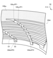
螺旋溝120ssは、軸部材200の外周面200opに巻きつくように、螺旋状に設けられる。本実施形態では、図2に示すように、4本の螺旋溝120ssが設けられた場合を想定する。例えば、図1の経路RT1は、4本の螺旋溝120ssのうちの1本の螺旋溝120ssの経路の一例を示している。図1に示した経路RT1のうち、破線で示した部分は、軸部材200に対して-X方向に位置する螺旋溝120ssの経路を示し、二点鎖線で示した部分は、軸部材200に対して+X方向に位置する螺旋溝120ssの経路を示している。
The spiral groove 120ss is provided in a spiral shape so as to wind around the outer peripheral surface 200op of the
螺旋溝120ssは、軸部材200の回転によってポンプ作用が発生するように、設けられている。例えば、軸部材200が中心軸AXを回転軸として回転方向DR(時計回り)に回転すると、ポンプ作用により、螺旋溝120ss等に存在するオイルを第2空間SP2から第1空間SP1に戻す流れ(オイルを第1空間SP1側へ押し戻す力)が発生する。これにより、第1空間SP1に充填されているオイルが、第1空間SP1から第2空間SP2に漏れ出すことを防止することができる。
The spiral groove 120ss is provided so that a pumping action occurs when the
また、圧抜き溝120dsは、曲線状の曲部を有し、経路長が螺旋溝120ssの経路長より短くなるように設けられている。本実施形態では、図2に示すように、16本の圧抜き溝120dsが設けられた場合を想定する。例えば、図1の経路RT2は、16本の圧抜き溝120dsのうちの1本の圧抜き溝120dsの経路の一例を示している。図1に示した経路RT2のうち、破線で示した部分は、軸部材200に対して-X方向に位置する圧抜き溝120dsの経路を示している。
The pressure relief groove 120ds has a curved bend and is provided so that the path length is shorter than the path length of the spiral groove 120ss. In this embodiment, as shown in FIG. 2, it is assumed that 16 pressure relief grooves 120ds are provided. For example, the path RT2 in FIG. 1 shows an example of the path of one of the 16 pressure relief grooves 120ds. The portion of the path RT2 shown in FIG. 1 that is indicated by a dashed line shows the path of the pressure relief groove 120ds that is located in the -X direction with respect to the
圧抜き溝120dsも、螺旋溝120ssと同様に、軸部材200の回転によってとポンプ作用が発生するように、設けられている。例えば、軸部材200が中心軸AXを回転軸として回転方向DR(時計回り)に回転すると、ポンプ作用により、圧抜き溝120ds等に存在するオイルを第2空間SP2から第1空間SP1に戻す流れ(オイルを第1空間SP1側へ押し戻す力)が発生する。
The pressure relief groove 120ds, like the spiral groove 120ss, is provided so that a pumping action occurs when the
なお、例えば、第2空間SP2から第1空間SP1にポンプ作用により蓄積された大気は、軸部材200が停止したときに、圧抜き溝120ds及び螺旋溝120ss(主に、圧抜き溝120ds)を介して、第1空間SP1から第2空間SP2に抜ける。密封装置100では、圧抜き溝120dsが設けられていない構成に比べて、第1空間SP1側から第2空間SP2側に気体が抜ける経路が増加するため、第1空間SP1に蓄積される圧力(気体)を低減することができる。さらに、本実施形態では、圧抜き溝120dsの経路長が螺旋溝120ssの経路長より短いため、軸部材200が停止したとき、又は、軸部材200の回転速度が低速になったときに、第1空間SP1に蓄積された圧力(気体)を効率よく逃がすことができる。
For example, the air accumulated from the second space SP2 to the first space SP1 by the pump action is released from the first space SP1 to the second space SP2 through the pressure relief groove 120ds and the spiral groove 120ss (mainly the pressure relief groove 120ds) when the
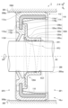
図2は、密封装置100がハウジング300に装着されていない状態における第2シール部120を+Z方向から見た正面図である。図2の破線の円は、図1に示した軸部材200の外周に対応する円を示している。
Figure 2 is a front view of the
図2に示す例では、4本の螺旋溝120ssの各々は、第2シール部120のシールリップ部120slにおける外周端部から内周端部にわたって、一本の螺旋状の溝として形成されている。なお、4本の螺旋溝120ssは、例えば、シールリップ部120slの外周側のそれぞれの端部がシールリップ部120slの外周に沿って等間隔又はほぼ等間隔になるように配置され、互いに同じ又はほぼ同じ螺旋状に形成されている。このため、図2に示す4本の螺旋溝120ssは、互いに交差することなく、配置されている。
In the example shown in FIG. 2, each of the four spiral grooves 120ss is formed as a single spiral groove from the outer peripheral end to the inner peripheral end of the seal lip portion 120sl of the
また、16本の圧抜き溝120dsの各々は、第2シール部120のシールリップ部120slにおける外周端部から内周端部にわたって、経路長が螺旋溝120ssの経路長より短い曲線状の溝として形成されている。図2に示す例では、螺旋溝120ssが穴HLbの周りをほぼ2周しているのに対して、圧抜き溝120dsは、穴HLbの周りを1周することなく、第2シール部120のシールリップ部120slにおける外周端部から内周端部に到達している。
Each of the 16 pressure relief grooves 120ds is formed as a curved groove whose path length is shorter than the path length of the spiral groove 120ss from the outer peripheral end to the inner peripheral end of the seal lip portion 120sl of the
例えば、螺旋溝120ssにおける経路RT1の延在方向は、圧抜き溝120dsにおける経路RT2の延在方向に比べて、軸部材200の回転方向DRに対して平行に近い。このため、螺旋溝120ssに起因するポンプ作用は、圧抜き溝120dsに起因するポンプ作用に比べて大きくなる。換言すれば、圧抜き溝120dsに起因するポンプ作用は、螺旋溝120ssに起因するポンプ作用に比べて小さい。したがって、軸部材200の回転速度を低くしていくと、螺旋溝120ssに起因するポンプ作用は発生するが、圧抜き溝120dsに起因するポンプ作用は発生しない回転速度が存在する。例えば、本実施形態では、軸部材200の回転速度が、圧抜き溝120dsに起因するポンプ作用が発生しない回転速度以下になると、第1空間SP1に蓄積された圧力(気体)を圧抜き溝120dsから第2空間SP2側(大気側)に逃がすことが可能となる。
For example, the extension direction of the path RT1 in the spiral groove 120ss is closer to parallel to the rotation direction DR of the
なお、圧抜き溝120dsは、穴HLbの周りを回る量が螺旋溝120ssが穴HLbの周りを回る量より少なければ、穴HLbの周りを1周以上するように形成されてもよい。すなわち、圧抜き溝120dsは、経路長が螺旋溝120ssの経路長より短ければ、穴HLbの周りを1周以上するように形成されてもよい。 The pressure relief groove 120ds may be formed to make one or more revolutions around the hole HLb, provided that the amount by which it turns around the hole HLb is less than the amount by which the spiral groove 120ss turns around the hole HLb. In other words, the pressure relief groove 120ds may be formed to make one or more revolutions around the hole HLb, provided that the path length of the pressure relief groove 120ds is shorter than the path length of the spiral groove 120ss.
また、16本の圧抜き溝120dsの各々は、例えば、シールリップ部120slの外周側のそれぞれの端部がシールリップ部120slの外周に沿って等間隔又はほぼ等間隔になるように配置され、互いに同じ又はほぼ同じ曲線状に形成されている。そして、16本の圧抜き溝120dsの各々は、4本の螺旋溝120ssの各々と交差している。 The 16 pressure relief grooves 120ds are arranged such that their ends on the outer periphery of the seal lip portion 120sl are equally spaced or nearly equally spaced along the outer periphery of the seal lip portion 120sl, and are formed in the same or nearly the same curved shape. Each of the 16 pressure relief grooves 120ds intersects with each of the four spiral grooves 120ss.
なお、螺旋溝120ssの数は、4本に限定されない。例えば、螺旋溝120ssの数は、1本以上、3本以下でもよい。あるいは、螺旋溝120ssの数は、5本以上でもよい。同様に、圧抜き溝120dsの数は、16本に限定されない。例えば、圧抜き溝120dsの数は、1本以上、15本以下でもよい。あるいは、圧抜き溝120dsの数は、17本以上でもよい。また、図2に示す例では、圧抜き溝120dsの数を螺旋溝120ssの数より多くすることにより、第1空間SP1に蓄積された圧力(気体)を効率よく逃がしている。但し、圧抜き溝120dsの数は、螺旋溝120ssの数と同じでもよいし、螺旋溝120ssの数より少なくてもよい。また、例えば、螺旋溝120ssの数及び圧抜き溝120dsの数がそれぞれ1本の場合等では、圧抜き溝120dsは、螺旋溝120ssと交差してもよいし、螺旋溝120ssと交差しなくてもよい。 The number of spiral grooves 120ss is not limited to four. For example, the number of spiral grooves 120ss may be one or more and three or less. Alternatively, the number of spiral grooves 120ss may be five or more. Similarly, the number of pressure relief grooves 120ds is not limited to 16. For example, the number of pressure relief grooves 120ds may be one or more and fifteen or less. Alternatively, the number of pressure relief grooves 120ds may be seventeen or more. In the example shown in FIG. 2, the number of pressure relief grooves 120ds is greater than the number of spiral grooves 120ss, so that the pressure (gas) accumulated in the first space SP1 is efficiently released. However, the number of pressure relief grooves 120ds may be the same as the number of spiral grooves 120ss, or may be less than the number of spiral grooves 120ss. Also, for example, when the number of spiral grooves 120ss and the number of pressure relief grooves 120ds are each one, the pressure relief groove 120ds may or may not intersect with the spiral groove 120ss.
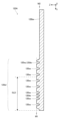
図3は、螺旋溝120ss及び圧抜き溝120dsの一例を示す斜視図である。なお、図3は、図2における範囲AR1を拡大した斜視図である。すなわち、図3では、密封装置100がハウジング300に装着されていない場合を想定する。図3の網掛けは、+Z方向の位置が、第2シール部120の基端部120beと同じ位置又はほぼ同じ位置の面を示している。すなわち、密封装置100がハウジング300に装着されていない場合、シールリップ部120slの表面(+Z方向から見える面)の+Z方向の位置は、基端部120beの表面(+Z方向から見える面)の+Z方向の位置と同じ又はほぼ同じである。したがって、密封装置100がハウジング300に装着されていない場合、螺旋溝120ss及び圧抜き溝120dsは、基端部120beに対して-Z方向に凹んでいる。本実施形態では、螺旋溝120ssの深さD1と圧抜き溝120dsの深さD2とは互いに同じである。
Figure 3 is a perspective view showing an example of the spiral groove 120ss and the pressure relief groove 120ds. Note that Figure 3 is a perspective view in which the range AR1 in Figure 2 is enlarged. That is, in Figure 3, it is assumed that the
本実施形態では、螺旋溝120ssの深さD1、圧抜き溝120dsの深さD2、螺旋溝120ssの本数及び圧抜き溝120dsの本数等を調整することにより、密封対象のオイルを第1空間SP1から漏らさずに圧力(気体)のみを第2空間SP2に逃がすことが可能となる。 In this embodiment, by adjusting the depth D1 of the spiral groove 120ss, the depth D2 of the pressure relief groove 120ds, the number of spiral grooves 120ss, and the number of pressure relief grooves 120ds, it is possible to release only the pressure (gas) into the second space SP2 without leaking the oil to be sealed from the first space SP1.
以上、本実施形態では、密封装置100は、ハウジング300の内周面300ipに接触する環状の第1シール部110と、軸部材200の外周面200opに摺動する環状の第2シール部120とを有する。そして、第2シール部120には、軸部材200の外周面200opに摺動する摺動面SLDに、第1空間SP1から第2空間SP2にわたる螺旋溝120ssと、第1空間SP1から第2空間SP2にわたる圧抜き溝120dsとが設けられている。なお、圧抜き溝120dsの経路長は、螺旋溝120ssの経路長より短い。例えば、圧抜き溝120dsは、螺旋溝120ssと交差している。
As described above, in this embodiment, the
また、例えば、螺旋溝120ssは、軸部材200の回転時に密封対象の流体を第2空間SP2から第1空間SP1に戻す流れを発生させるように、螺旋状に形成される。圧抜き溝120dsは、軸部材200の回転時に密封対象の流体を第2空間SP2から第1空間SP1に戻す流れを発生させるように、曲線状の曲部を有する。これにより、本実施形態では、第1空間SP1に密封された流体が、第1空間SP1から第2空間SP2に漏れ出すことを防止することができる。
For example, the spiral groove 120ss is formed in a spiral shape so as to generate a flow that returns the fluid to be sealed from the second space SP2 to the first space SP1 when the
また、本実施形態では、上述したように、第2シール部120には、螺旋溝120ssの他に圧抜き溝120dsが設けられている。このため、本実施形態では、螺旋溝120ss等に起因するポンプ作用により第2空間SP2から第1空間SP1に蓄積された圧力(気体)を、第1空間SP1から第2空間SP2に逃がす経路は、圧抜き溝120dsが設けられていない構成に比べて、増加する。したがって、本実施形態では、圧抜き溝120dsが設けられていない構成に比べて、第1空間SP1に蓄積される圧力(気体)を低減することができる。また、本実施形態では、圧抜き溝120dsの経路長が螺旋溝120ssの経路長より短いため、軸部材200が停止したとき、又は、軸部材200の回転速度が低く、螺旋溝120ssのポンプ作用が低いときに、第1空間SP1に蓄積された圧力(気体)を効率よく逃がすことができる。
In addition, in this embodiment, as described above, the
また、例えば、圧抜き溝120dsの本数が螺旋溝120ssの本数より多い場合、第1空間SP1に蓄積された圧力(気体)を効率よく逃がすことができる。 For example, if the number of pressure relief grooves 120ds is greater than the number of spiral grooves 120ss, the pressure (gas) accumulated in the first space SP1 can be efficiently released.
このように、本実施形態では、第1空間SP1等の密封空間の流体が外部に漏れることを抑制しつつ、密封空間に蓄積された圧力を逃がすことができる。この結果、本実施形態では、軸部材200が停止した場合に、密封空間の圧力が正常時の密封空間の圧力に比べて高い状態に維持されることを抑制でき、密封空間及び密封空間の周辺の部品に悪影響を与えることを低減することができる。
In this manner, in this embodiment, the pressure accumulated in the sealed space can be released while preventing the fluid in the sealed space, such as the first space SP1, from leaking to the outside. As a result, in this embodiment, when the
[2.変形例]
以上に例示した実施形態は多様に変形され得る。前述の実施形態に適用され得る具体的な変形の態様を以下に例示する。以下の例示から任意に選択された2以上の態様を、相互に矛盾しない範囲で併合してもよい。
2. Modifications
The above-described embodiment may be modified in various ways. Specific modified aspects that may be applied to the above-described embodiment are exemplified below. Two or more aspects selected from the following examples may be combined to the extent that they are not mutually contradictory.
[変形例1]
上述した実施形態では、密封装置100がハウジング300に装着されていない場合における螺旋溝120ss及び圧抜き溝120dsが、基端部120beに対して-Z方向に凹んでいる態様を例示したが、本発明はこのような態様に限定されるものではない。例えば、密封装置100がハウジング300に装着されていない場合における螺旋溝120ssの壁及び圧抜き溝120dsの壁は、図5に示すように、基端部120beに対して+Z方向に突出していてもよい。
[Modification 1]
In the above-described embodiment, the spiral groove 120ss and the pressure relief groove 120ds are recessed in the -Z direction relative to the base end 120be when the
図4は、変形例1に係る密封装置100Aがハウジング300に装着された状態を示す模式的断面図である。なお、図4は、密封装置100Aを軸部材200の中心軸AXを通る平面で切断した場合(密封装置100Aを図2に示したA1-A2線により切断した場合)の密封装置100Aの断面図を模式的に示している。図1から図3において説明した要素と同様の要素については、同様の符号を付し、詳細な説明を省略する。
Figure 4 is a schematic cross-sectional view showing the state in which the
密封装置100Aは、図1に示した第2シール部120の代わりに第2シール部120Aを有することを除いて、図1に示した密封装置100と同様である。図5を参照しながら、変形例1に係る第2シール部120Aいついて説明する。
The
図5は、変形例1に係る第2シール部120Aの断面図である。なお、図5は、図2に示した範囲AR1に対応する部分の第2シール部120Aを図2に示したA1-A2線により切断した場合における第2シール部120Aの断面図を示している。
Figure 5 is a cross-sectional view of the
密封装置100がハウジング300に装着されていない場合、第2シール部120Aのシールリップ部120slの表面M1(+Z方向から見える面)は、基端部120beの表面M2(+Z方向から見える面)に対して+Z方向に位置する。そして、第2シール部120Aのシールリップ部120slの表面M1(+Z方向から見える面)に、螺旋溝120ss及び圧抜き溝120dsが設けられている。すなわち、第2シール部120Aにおいても、軸部材200の外周面200opに摺動する摺動面SLDに、螺旋溝120ss及び圧抜き溝120dsが設けられている。図5に示す変形例1では、密封装置100がハウジング300に装着されていない場合、螺旋溝120ssの底面及び圧抜き溝120dsの底面の+Z方向の位置は、第2シール部120Aの基端部120beの表面M2(+Z方向から見える面)の+Z方向の位置と同じ又はほぼ同じである。
When the
変形例1においても、上述した実施形態と同様の効果を得ることができる。例えば、変形例1においても、第1空間SP1等の密封空間の流体が外部に漏れることを抑制しつつ、密封空間に蓄積された圧力を逃がすことができる。 In the first modification, the same effect as in the above-described embodiment can be obtained. For example, in the first modification, the pressure accumulated in the sealed space can be released while preventing the fluid in the sealed space, such as the first space SP1, from leaking to the outside.
[変形例2]
上述した実施形態及び変形例1では、螺旋溝120ssの深さD1と圧抜き溝120dsの深さD2とが互いに同じである態様を例示したが、本発明はこのような態様に限定されるものではない。例えば、摺動面SLDに対する圧抜き溝120dsの深さD2は、摺動面SLDに対する螺旋溝120ssの深さD1と異なる深さでもよい。
[Modification 2]
In the above-described embodiment and modified example 1, the depth D1 of the spiral groove 120ss and the depth D2 of the pressure relief groove 120ds are the same as each other, but the present invention is not limited to such an embodiment. For example, the depth D2 of the pressure relief groove 120ds relative to the sliding surface SLD may be different from the depth D1 of the spiral groove 120ss relative to the sliding surface SLD.
図6は、変形例2に係る密封装置100Bがハウジング300に装着された状態を示す模式的断面図である。なお、図6は、密封装置100Bを軸部材200の中心軸AXを通る平面で切断した場合(密封装置100Bを図2に示したA1-A2線により切断した場合)の密封装置100Bの断面図を模式的に示している。図1から図5において説明した要素と同様の要素については、同様の符号を付し、詳細な説明を省略する。
Figure 6 is a schematic cross-sectional view showing a state in which a
密封装置100Bは、図1に示した第2シール部120の代わりに第2シール部120Bを有することを除いて、図1に示した密封装置100と同様である。図7を参照しながら、変形例2に係る第2シール部120Bいついて説明する。
The
図7は、変形例2に係る第2シール部120Bの断面図である。なお、図7は、図2に示した範囲AR1に対応する部分の第2シール部120Bを図2に示したA1-A2線により切断した場合における第2シール部120Bの断面図を示している。図1から図5において説明した要素と同様の要素については、同様の符号を付し、詳細な説明を省略する。
Figure 7 is a cross-sectional view of the
図7に示す第2シール部120Bは、圧抜き溝120dsの深さD2を除いて、図1から図3に示した第2シール部120と同様である。第2シール部120Bは、摺動面SLDに対する圧抜き溝120dsの深さD2が摺動面SLDに対する螺旋溝120ssの深さD1よりも浅くなるように、形成されている。
The
変形例2においても、上述した実施形態と同様の効果を得ることができる。例えば、変形例2においても、第1空間SP1等の密封空間の流体が外部に漏れることを抑制しつつ、密封空間に蓄積された圧力を逃がすことができる。また、図7に示した変形例2では、摺動面SLDに対する圧抜き溝120dsの深さD2が摺動面SLDに対する螺旋溝120ssの深さD1よりも浅い。このため、図7に示した変形例2では、摺動面SLDに対する圧抜き溝120dsの深さD2が摺動面SLDに対する螺旋溝120ssの深さD1と同じ場合に比べて、第1空間SP1に密封された流体が第2空間SP2に漏れることを抑制することができる。 In the second modification, the same effect as in the above-described embodiment can be obtained. For example, in the second modification, the pressure accumulated in the sealed space, such as the first space SP1, can be released while suppressing leakage of the fluid in the sealed space to the outside. In the second modification shown in FIG. 7, the depth D2 of the pressure relief groove 120ds relative to the sliding surface SLD is shallower than the depth D1 of the spiral groove 120ss relative to the sliding surface SLD. Therefore, in the second modification shown in FIG. 7, the fluid sealed in the first space SP1 can be suppressed from leaking into the second space SP2, compared to the case where the depth D2 of the pressure relief groove 120ds relative to the sliding surface SLD is the same as the depth D1 of the spiral groove 120ss relative to the sliding surface SLD.
なお、摺動面SLDに対する圧抜き溝120dsの深さD2は、摺動面SLDに対する螺旋溝120ssの深さD1より深くてもよい。変形例2においても、螺旋溝120ssの深さD1、圧抜き溝120dsの深さD2、螺旋溝120ssの本数及び圧抜き溝120dsの本数等を調整することにより、密封対象のオイル等の流体を第1空間SP1から漏らさずに圧力(気体)のみを第2空間SP2に逃がすことが可能となる。 The depth D2 of the pressure relief groove 120ds relative to the sliding surface SLD may be greater than the depth D1 of the spiral groove 120ss relative to the sliding surface SLD. In the second modification, by adjusting the depth D1 of the spiral groove 120ss, the depth D2 of the pressure relief groove 120ds, the number of the spiral grooves 120ss, and the number of the pressure relief grooves 120ds, it is possible to release only the pressure (gas) into the second space SP2 without leaking the fluid to be sealed, such as oil, from the first space SP1.
[変形例3]
上述した実施形態、変形例1及び変形例2では、第2シール部120、120A及び120Bの各々の基端部120beが第1シール部110の支持部112spに設けられた円筒部112clの内周面に嵌め込まれる態様を例示したが、本発明はこのような態様に限定されるものではない。例えば、第2シール部120、120A及び120Bの各々の基端部120beは、図8に示すように、第1シール部110の補強環114における円筒部114clの内周面に嵌め込まれてもよい。
[Modification 3]
In the above-described embodiment, modified example 1, and modified example 2, the base end 120be of each of the
図8は、変形例3に係る密封装置100Cがハウジング300に装着された状態を示す模式的断面図である。なお、図8は、密封装置100Cを軸部材200の中心軸AXを通る平面で切断した場合(密封装置100Cを図2に示したA1-A2線により切断した場合)の密封装置100Cの断面図を模式的に示している。図1から図7において説明した要素と同様の要素については、同様の符号を付し、詳細な説明を省略する。
Figure 8 is a schematic cross-sectional view showing a state in which a
密封装置100Cは、図1に示した第1シール部110の代わりに第1シール部110Cを有し、図1に示した第2シール部120の代わりに第2シール部120Cを有している。
The
第1シール部110Cは、図1に示した弾性環112の代わりに弾性環112C有することを除いて、図1に示した第1シール部110と同様である。弾性環112Cと図1に示した弾性環112との主な相違点は、弾性環112Cが支持部112spの代わりに支持部112Cspを有する点である。また、支持部112Cspと図1に示した支持部112spとの主な相違点は、支持部112Cspには図1に示した円筒部112clが設けられていない点である。
The
第2シール部120Cは、第1シール部110Cの補強環114における円筒部114clの内周面に嵌め込まれる基端部120Cbeを図1に示した基端部120beの代わりに有することを除いて、図1に示した第2シール部120と同様である。すなわち、密封装置100Cでは、第2シール部120Cの基端部120Cbeは、第1シール部110Cの補強環114における円筒部114clの内周面に所定の締め代を有して嵌め込まれる。これにより、第2シール部120Cの基端部120Cbeが第1シール部110Cの支持部112Csp及び補強環114の円筒部114clに接続され、第2シール部120Cが第1シール部110Cに対して固定される。なお、第2シール部120Cの固定方法は、円筒部114clへの嵌め込みによる接続に限定されない。例えば、第2シール部120Cの基端部120Cbeは、第1シール部110の支持部112Csp及び補強環114の円筒部114clに接着されてもよい。
The
変形例3においても、上述した実施形態と同様の効果を得ることができる。例えば、変形例3においても、第1空間SP1等の密封空間の流体が外部に漏れることを抑制しつつ、密封空間に蓄積された圧力を逃がすことができる。 In the third modification, the same effect as in the above-described embodiment can be obtained. For example, in the third modification, the pressure accumulated in the sealed space, such as the first space SP1, can be released while preventing the fluid in the sealed space from leaking to the outside.
100、100A、100B、100C…密封装置、110、110C…第1シール部、112、112C…弾性環、112cl…円筒部、112dl…ダストリップ部、112jo…連結部、112os…外周シール部、112sp、112Csp…支持部、114…補強環、114cl…円筒部、114fg…フランジ部、120、120A、120B、120C…第2シール部、120be、120Cbe…基端部、120ds…圧抜き溝、120sl…シールリップ部、120ss…螺旋溝、200…軸部材、200op…外周面、300…ハウジング、300ip…内周面、AX…中心軸、HLa…軸孔、HLb…穴、SLD…摺動面、SP1…第1空間、SP2…第2空間。 100, 100A, 100B, 100C...sealing device, 110, 110C...first seal portion, 112, 112C...elastic ring, 112cl...cylindrical portion, 112dl...dust lip portion, 112jo...connection portion, 112os...periphery seal portion, 112sp, 112Csp...support portion, 114...reinforcing ring, 114cl...cylindrical portion, 114fg...flange portion, 120, 120 A, 120B, 120C...second seal portion, 120be, 120Cbe...base end portion, 120ds...pressure relief groove, 120sl...seal lip portion, 120ss...spiral groove, 200...shaft member, 200op...outer peripheral surface, 300...housing, 300ip...inner peripheral surface, AX...center axis, HLa...shaft hole, HLb...hole, SLD...sliding surface, SP1...first space, SP2...second space.
Claims (5)
前記収納部材の内周面に接触する環状の第1部分と、
前記軸部材の外周面に摺動する環状の第2部分とを有し、
前記第2部分には、
前記軸部材の外周面と摺動する摺動面に、
前記第1空間から前記第2空間にわたり、且つ、螺旋状の第1溝部と、
前記第1空間から前記第2空間にわたり、且つ、曲線状の曲部を有する第2溝部とが設けられ、
前記第2溝部の経路長は、前記第1溝部の経路長より短い、
ことを特徴とする密封装置。 A sealing device that divides a space between a storage member having an axial hole and a shaft member inserted into the axial hole into a first space and a second space,
an annular first portion in contact with an inner circumferential surface of the storage member;
a second annular portion that slides on an outer circumferential surface of the shaft member;
The second portion includes:
A sliding surface that slides against the outer circumferential surface of the shaft member,
a first groove portion extending from the first space to the second space and having a spiral shape;
a second groove portion extending from the first space to the second space and having a curved portion;
The path length of the second groove portion is shorter than the path length of the first groove portion.
A sealing device characterized by:
ことを特徴とする請求項1に記載の密封装置。 The second groove portion intersects with the first groove portion.
The sealing device according to claim 1 .
ことを特徴とする請求項1又は2に記載の密封装置。 A depth of the second groove portion from the sliding surface is shallower than a depth of the first groove portion from the sliding surface.
3. The sealing device according to claim 1 or 2.
ことを特徴とする請求項1から3のいずれか1項に記載の密封装置。 The number of the second groove portions is greater than the number of the first groove portions.
The sealing device according to any one of claims 1 to 3.
前記第1溝部は、前記軸部材の回転時に前記密封対象の流体を前記第2空間から前記第1空間に戻す流れを発生させ、
前記第2溝部は、前記軸部材の回転時に前記密封対象の流体を前記第2空間から前記第1空間に戻す流れを発生させる、
ことを特徴とする請求項1から4のいずれか1項に記載の密封装置。 The first space is filled with a fluid to be sealed, and a gas is present in the second space,
the first groove portion generates a flow that returns the fluid to be sealed from the second space to the first space when the shaft member rotates;
The second groove portion generates a flow that returns the fluid to be sealed from the second space to the first space when the shaft member rotates.
The sealing device according to any one of claims 1 to 4.
Priority Applications (3)
| Application Number | Priority Date | Filing Date | Title |
|---|---|---|---|
| JP2021066344A JP7535472B2 (en) | 2021-04-09 | 2021-04-09 | Sealing device |
| CN202210294346.1A CN115199751B (en) | 2021-04-09 | 2022-03-24 | Sealing device |
| DE102022108077.3A DE102022108077B4 (en) | 2021-04-09 | 2022-04-05 | SEALING DEVICE |
Applications Claiming Priority (1)
| Application Number | Priority Date | Filing Date | Title |
|---|---|---|---|
| JP2021066344A JP7535472B2 (en) | 2021-04-09 | 2021-04-09 | Sealing device |
Publications (2)
| Publication Number | Publication Date |
|---|---|
| JP2022161481A JP2022161481A (en) | 2022-10-21 |
| JP7535472B2 true JP7535472B2 (en) | 2024-08-16 |
Family
ID=83361996
Family Applications (1)
| Application Number | Title | Priority Date | Filing Date |
|---|---|---|---|
| JP2021066344A Active JP7535472B2 (en) | 2021-04-09 | 2021-04-09 | Sealing device |
Country Status (3)
| Country | Link |
|---|---|
| JP (1) | JP7535472B2 (en) |
| CN (1) | CN115199751B (en) |
| DE (1) | DE102022108077B4 (en) |
Families Citing this family (1)
| Publication number | Priority date | Publication date | Assignee | Title |
|---|---|---|---|---|
| CN121007218A (en) * | 2025-10-27 | 2025-11-25 | 中国石油大学(华东) | A sand-proof seal structure and sealing method for a submersible electric pump piston |
Citations (3)
| Publication number | Priority date | Publication date | Assignee | Title |
|---|---|---|---|---|
| JP2000055209A (en) | 1998-08-10 | 2000-02-22 | Nok Corp | Sealing device |
| CN206754365U (en) | 2017-03-30 | 2017-12-15 | 浙江工业大学 | A kind of end surface mechanical sealing structure of imitative shark skin surface three-dimensional appearance |
| CN108591467A (en) | 2018-04-20 | 2018-09-28 | 舍弗勒技术股份两合公司 | Sealing structure |
Family Cites Families (13)
| Publication number | Priority date | Publication date | Assignee | Title |
|---|---|---|---|---|
| JP3415266B2 (en) * | 1994-05-24 | 2003-06-09 | 三菱電線工業株式会社 | Rotary shaft seal |
| JP4396790B2 (en) * | 1999-12-14 | 2010-01-13 | Nok株式会社 | Oil seal |
| JP4600633B2 (en) * | 2001-09-20 | 2010-12-15 | Nok株式会社 | Oil seal |
| JP2005273691A (en) * | 2004-03-23 | 2005-10-06 | Nok Corp | Shaft sealing structure by seal lip |
| DE102006025799B4 (en) * | 2006-06-02 | 2017-11-23 | Ab Skf | sealing element |
| DE102006026812B4 (en) * | 2006-06-09 | 2016-04-07 | Ab Skf | Seal for a compressor |
| JP5158357B2 (en) * | 2008-06-09 | 2013-03-06 | Nok株式会社 | Sealing device |
| DE102010042555B4 (en) | 2010-10-18 | 2015-10-08 | Aktiebolaget Skf | Radial shaft seal |
| JP5637172B2 (en) * | 2012-04-27 | 2014-12-10 | Nok株式会社 | Sealing device |
| JP5296913B1 (en) * | 2012-10-02 | 2013-09-25 | 株式会社小松製作所 | Engine unit |
| JP6054135B2 (en) * | 2012-10-23 | 2016-12-27 | Nok株式会社 | Oil seal |
| CN108999683A (en) * | 2018-07-17 | 2018-12-14 | 山东艾泰克环保科技股份有限公司 | A kind of After-treatment technics packaging system |
| CN210397653U (en) * | 2019-07-10 | 2020-04-24 | 陕西奉航橡胶密封件有限责任公司 | Novel heavy truck gearbox output shaft combined oil seal |
-
2021
- 2021-04-09 JP JP2021066344A patent/JP7535472B2/en active Active
-
2022
- 2022-03-24 CN CN202210294346.1A patent/CN115199751B/en active Active
- 2022-04-05 DE DE102022108077.3A patent/DE102022108077B4/en active Active
Patent Citations (3)
| Publication number | Priority date | Publication date | Assignee | Title |
|---|---|---|---|---|
| JP2000055209A (en) | 1998-08-10 | 2000-02-22 | Nok Corp | Sealing device |
| CN206754365U (en) | 2017-03-30 | 2017-12-15 | 浙江工业大学 | A kind of end surface mechanical sealing structure of imitative shark skin surface three-dimensional appearance |
| CN108591467A (en) | 2018-04-20 | 2018-09-28 | 舍弗勒技术股份两合公司 | Sealing structure |
Also Published As
| Publication number | Publication date |
|---|---|
| JP2022161481A (en) | 2022-10-21 |
| DE102022108077B4 (en) | 2024-02-22 |
| DE102022108077A1 (en) | 2022-10-13 |
| CN115199751B (en) | 2025-08-05 |
| CN115199751A (en) | 2022-10-18 |
Similar Documents
| Publication | Publication Date | Title |
|---|---|---|
| US6921080B2 (en) | Shaft sealing ring | |
| JP6374961B2 (en) | Sealing device | |
| JP6961094B2 (en) | Sealing device | |
| MXPA05003406A (en) | Unitizing element and method for assembling a seal. | |
| JPS6233470B2 (en) | ||
| EP3321547B1 (en) | Seal assembly for a rotating member | |
| JP2011174570A (en) | Sealing device | |
| JP7535472B2 (en) | Sealing device | |
| CN110259949A (en) | Sealing device | |
| WO2024128274A1 (en) | Seal ring | |
| JP7644771B2 (en) | Sealing device | |
| JP2007107547A (en) | Seal ring | |
| WO2010143694A1 (en) | Sealing device | |
| JP7130863B2 (en) | sealing device | |
| US20240044409A1 (en) | Rotary seal assembly with oil-side foam ring | |
| WO2015120899A1 (en) | Dynamic seal | |
| JP4938309B2 (en) | Sealing device | |
| JP2014114830A (en) | Sealed rolling bearing | |
| JP2010060120A (en) | Sealing device | |
| JP6995005B2 (en) | Sealing device | |
| JP2018100730A (en) | Sealing device | |
| JP2021156314A (en) | Sealing device | |
| JP6868983B2 (en) | Sealing device | |
| WO2022264255A1 (en) | Sealing device | |
| JP5823290B2 (en) | Needle bearing assembly with sealing device |
Legal Events
| Date | Code | Title | Description |
|---|---|---|---|
| A621 | Written request for application examination |
Free format text: JAPANESE INTERMEDIATE CODE: A621 Effective date: 20231115 |
|
| A977 | Report on retrieval |
Free format text: JAPANESE INTERMEDIATE CODE: A971007 Effective date: 20240710 |
|
| TRDD | Decision of grant or rejection written | ||
| A01 | Written decision to grant a patent or to grant a registration (utility model) |
Free format text: JAPANESE INTERMEDIATE CODE: A01 Effective date: 20240730 |
|
| A61 | First payment of annual fees (during grant procedure) |
Free format text: JAPANESE INTERMEDIATE CODE: A61 Effective date: 20240805 |
|
| R150 | Certificate of patent or registration of utility model |
Ref document number: 7535472 Country of ref document: JP Free format text: JAPANESE INTERMEDIATE CODE: R150 |