JP7533859B2 - Bone repair implant and method of manufacturing same - Google Patents
Bone repair implant and method of manufacturing same Download PDFInfo
- Publication number
- JP7533859B2 JP7533859B2 JP2020535746A JP2020535746A JP7533859B2 JP 7533859 B2 JP7533859 B2 JP 7533859B2 JP 2020535746 A JP2020535746 A JP 2020535746A JP 2020535746 A JP2020535746 A JP 2020535746A JP 7533859 B2 JP7533859 B2 JP 7533859B2
- Authority
- JP
- Japan
- Prior art keywords
- bone
- plate
- shaped portion
- implant
- repair implant
- Prior art date
- Legal status (The legal status is an assumption and is not a legal conclusion. Google has not performed a legal analysis and makes no representation as to the accuracy of the status listed.)
- Active
Links
Images


Classifications
-
- A—HUMAN NECESSITIES
- A61—MEDICAL OR VETERINARY SCIENCE; HYGIENE
- A61B—DIAGNOSIS; SURGERY; IDENTIFICATION
- A61B17/00—Surgical instruments, devices or methods
- A61B17/56—Surgical instruments or methods for treatment of bones or joints; Devices specially adapted therefor
-
- A—HUMAN NECESSITIES
- A61—MEDICAL OR VETERINARY SCIENCE; HYGIENE
- A61F—FILTERS IMPLANTABLE INTO BLOOD VESSELS; PROSTHESES; DEVICES PROVIDING PATENCY TO, OR PREVENTING COLLAPSING OF, TUBULAR STRUCTURES OF THE BODY, e.g. STENTS; ORTHOPAEDIC, NURSING OR CONTRACEPTIVE DEVICES; FOMENTATION; TREATMENT OR PROTECTION OF EYES OR EARS; BANDAGES, DRESSINGS OR ABSORBENT PADS; FIRST-AID KITS
- A61F2/00—Filters implantable into blood vessels; Prostheses, i.e. artificial substitutes or replacements for parts of the body; Appliances for connecting them with the body; Devices providing patency to, or preventing collapsing of, tubular structures of the body, e.g. stents
- A61F2/02—Prostheses implantable into the body
- A61F2/28—Bones
Landscapes
- Health & Medical Sciences (AREA)
- Life Sciences & Earth Sciences (AREA)
- Animal Behavior & Ethology (AREA)
- General Health & Medical Sciences (AREA)
- Surgery (AREA)
- Engineering & Computer Science (AREA)
- Biomedical Technology (AREA)
- Heart & Thoracic Surgery (AREA)
- Veterinary Medicine (AREA)
- Public Health (AREA)
- Orthopedic Medicine & Surgery (AREA)
- Oral & Maxillofacial Surgery (AREA)
- Cardiology (AREA)
- Vascular Medicine (AREA)
- Nuclear Medicine, Radiotherapy & Molecular Imaging (AREA)
- Transplantation (AREA)
- Medical Informatics (AREA)
- Molecular Biology (AREA)
- Prostheses (AREA)
- Materials For Medical Uses (AREA)
Description
本発明は、骨損傷部に設置される骨修復インプラントに関する。 The present invention relates to a bone repair implant for placement in a damaged bone area.
従来、種々の疾病や事故等で骨を部分的に欠損した場合、欠損した骨の代わりに自己の当該骨欠損部以外の骨を移植し、さらに金属等からなる固定具により固定することが行われている。 Conventionally, when bone is partially lost due to various diseases or accidents, the lost bone is replaced with a bone transplant from the patient's own bone other than the missing area, and then fixed in place with a fixing device made of metal or the like.
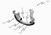
例えば、顎骨の場合、図14に示すように、顎骨100の骨欠損部Aに、他の部位から取得した骨101を移植し、顎骨100の形状に沿うように加工された金属製固定具102によって顎骨100と移植骨101とをつなぐ。具体的には金属製固定具102には長手方向に沿って複数の孔部103が設けられており、金属性固定具102はその孔部103を通るスクリュー等の締結具により顎骨100及び移植骨101に締結される。これにより、移植骨101は顎骨100に固定されることとなる。このような従来の方法を採用する場合、患者は骨欠損部A以外の骨を喪失することとなり、また、術者にとっても骨欠損部A以外からの骨採取、固定具102を顎骨形状に沿わせるための成形が必要となり、手術時間が長時間に亘ることとなり負担が大きい。For example, in the case of a jawbone, as shown in FIG. 14,
そこで、近年、骨形成誘導能を有するインプラントを骨欠損部に設置することが検討されている。このような方法を用いると、他の部位の骨を骨欠損部に移植する必要がなく、患者及び術者の負担を軽減することができる。このようなインプラントは、例えば特許文献1等に開示されている。特許文献1のインプラントは、チタンを材料として電子ビームを用いて造形された三次元メッシュ構造物に、骨形成因子(BMP)を複合化させることにより骨形成誘導を達成するものである。当該インプラントは、骨欠損部の形状の三次元座標データに基づいて製造されるため、形状制御が容易であり、さらにBMPを含むため、骨欠損部に設置することにより骨形成を誘導することができる。In recent years, therefore, the placement of an implant capable of inducing bone formation in a bone defect has been considered. By using such a method, it is not necessary to transplant bone from another site into the bone defect, and the burden on the patient and the surgeon can be reduced. Such an implant is disclosed, for example, in
また、上記BMPのような骨形成誘導因子を用いることなく、チタン材料に簡便な生体活性化処理を行うことにより、骨伝導による骨修復材料を製造する技術が特許文献2等に開示されている。具体的に、特許文献2では、チタンからなる基材に酸処理及び加熱処理をすることにより、当該基材の表面に生体骨との結合に有利なアパタイト層を形成できる旨が開示されている。Furthermore,
特許文献1のインプラントでは、骨形成誘導能を付加するためにBMPを用いているが、通常、基材となるチタンに直接BMPを付着させることは困難であるため、基材の表面処理を行ったり、BMPの付着後にデキストリン溶液を塗布したり、種々の処理が行われている。このため、製造工程が煩雑となるし、また、上記処理を行ったとしても十分な骨形成誘導能を発揮できる量のBMPをインプラントに付与できないおそれもある。加えて、BMPそのものが現在では、安価で大量生産不可能なことから臨床での使用には問題が残されている。さらに、特許文献1のインプラントは、骨欠損部の形状の三次元座標データに基づいて製造されているが、その形状は、単に骨欠損部に補綴する形状となっているだけであり、骨欠損部が生じた骨自体を固定・支持できるような構成とはなっていない。従って、実際には上述するような固定具が別途必要となる。In the implant of
また、特許文献2に開示の技術(さらに、非特許文献1~3も参照。)では、特許文献1のような処理を要せず、基材に対して酸処理および加熱処理といった簡便な処理のみでチタン板材やチタン多孔体に骨結合能(骨伝導能)や周囲に骨が存在しない環境下においても新生骨が誘導されることに関する動物実験の報告例がある。しかしながら、上記特許文献および非特許文献において、骨欠損部の修復に活用する方法を開示するものはない。さらに、特許文献2において、特許文献1と同様に、骨欠損部が生じた骨自体を固定できるような構成のインプラントについての開示は無い。
In addition, the technology disclosed in Patent Document 2 (see also
本発明は、前記の問題に鑑みてなされたものであり、その目的は、簡便な方法で骨損傷部を有する骨自体を支持及び固定でき、且つ、優れた骨形成能を有する骨修復インプラントを得ることにある。The present invention has been made in consideration of the above-mentioned problems, and its object is to obtain a bone repair implant that can support and fix the bone itself having a bone damage area in a simple manner and has excellent bone formation ability.
前記の目的を達成するために、患者の骨損傷部を有する骨の三次元座標データを利用して骨欠損部を有する骨の表面形状に対応する表面形状を有するインプラントを造形することで、従来のような手術者による形状加工を必要とせず、簡便に骨損傷部を有する骨に設置でき、当該骨を支持及び固定できる骨修復インプラントを完成した。 To achieve the above objective, by using three-dimensional coordinate data of a patient's bone with bone damage to create an implant with a surface shape that corresponds to the surface shape of a bone with a bone defect, we have completed a bone repair implant that can be easily placed on a bone with bone damage and can support and fix the bone without the need for shape processing by a surgeon as in the past.
本発明に係る骨修復インプラントは、患者の骨損傷部に設置するためのチタン又はチタン合金からなる骨修復インプラントであって、前記骨損傷部を有する骨の表面形状に対応する表面形状を少なくとも部分的に有する板状部を備え、前記板状部には、該板状部を前記骨損傷部の周囲の骨部分に締結するための締結具が通ることができる貫通孔が設けられていることを特徴とする。The bone repair implant of the present invention is a bone repair implant made of titanium or a titanium alloy for placement in a patient's damaged bone, and is characterized in that it has a plate-shaped portion having at least a partial surface shape that corresponds to the surface shape of a bone having the damaged bone, and the plate-shaped portion is provided with a through hole through which a fastener can pass for fastening the plate-shaped portion to the bone portion surrounding the damaged bone.
本発明に係る骨修復インプラントによると、骨損傷部を有する骨の表面形状に対応する表面形状で形成されているため、術中にインプラントを骨に適合するように成形する必要もなく、比較的容易に設置することができる。特に、本発明のインプラントにおける骨と接触する面の表面形状を少なくとも部分的に当該骨の表面形状に対応するように形成することで、少なくとも部分的にインプラントを当該骨と密接して設置することができる。これに加えて、本発明のインプラントには、締結具が通る貫通孔が設けられているため、締結具により、骨損傷部の周囲の骨部分に締結することにより、当該骨損傷部の周囲に位置する骨を一体的に容易に固定することができる。その結果、従来のような手術者による加工等を不要とすることができ、その負担を軽減できる。 The bone repair implant according to the present invention is formed with a surface shape corresponding to the surface shape of the bone having the bone damage, so there is no need to mold the implant to fit the bone during surgery, and it can be installed relatively easily. In particular, by forming the surface shape of the surface of the implant that contacts the bone to at least partially correspond to the surface shape of the bone, the implant can be installed at least partially in close contact with the bone. In addition, the implant according to the present invention has a through hole through which a fastener passes, so that the bone located around the bone damage can be easily fixed together by fastening it to the bone part around the bone damage with the fastener. As a result, processing by the surgeon as in the past is no longer necessary, and the burden on the surgeon can be reduced.
本発明に係る骨修復インプラントにおいて、前記板状部は、移植組織を設置するための空間をなす組織設置部を有するような形状に形成されていてもよい。In the bone repair implant of the present invention, the plate-shaped portion may be formed in a shape having a tissue installation portion that provides a space for installing transplant tissue.
このようにすると、上記組織設置部において板状部に骨修復のために重要な移植組織を設置でき、すなわち骨修復の促進に必要な血管や皮膚等の組織を配設できるスペースとしての組織設置部が形成されているため、それらの配設が容易となり、術者の作業負担を軽減することができる。In this way, transplant tissue important for bone repair can be placed in the plate-shaped portion of the tissue placement section, i.e., the tissue placement section is formed as a space in which blood vessels, skin, and other tissues necessary for promoting bone repair can be placed, making their placement easier and reducing the workload of the surgeon.
本発明に係る骨修復インプラントにおいて、前記板状部は、前記骨損傷部を有する骨を支持できる位置に設置されるように構成されており、当該設置部位の骨の表面形状に対応する表面形状を有していることが好ましい。例えば、前記板状部は、前記骨損傷部を有する骨の下部の表面形状に対応する表面形状を有し、前記板状部が前記骨損傷部の下部を覆って、前記骨損傷部を有する骨を下方から支持するように該骨損傷部を有する骨に設置される構成であってもよい。In the bone repair implant according to the present invention, the plate-shaped portion is configured to be installed at a position where it can support the bone having the bone damage portion, and preferably has a surface shape that corresponds to the surface shape of the bone at the installation site. For example, the plate-shaped portion may have a surface shape that corresponds to the surface shape of the lower part of the bone having the bone damage portion, and may be configured to be installed on the bone having the bone damage portion so as to cover the lower part of the bone damage portion and support the bone having the bone damage portion from below.
このようにすると、板状部が骨損傷部の下部を覆って、該骨損傷部を有する骨を下方から支持するため、骨損傷部を有する骨をインプラントにより固定した際の安定性を向上できる。また、固定前の設置手術中においても骨損傷部を有する骨を下方から支持できるため、インプラントの設置手術を容易にでき、術者の負担を軽減することができる。In this way, the plate-shaped portion covers the lower part of the damaged bone area and supports the bone with the damaged bone area from below, improving the stability when the bone with the damaged bone area is fixed with the implant. In addition, since the bone with the damaged bone area can be supported from below even during the installation surgery before fixation, the implant installation surgery can be facilitated and the burden on the surgeon can be reduced.
本発明に係る骨修復インプラントにおいて、前記板状部には、前記骨損傷部における骨損傷部分を少なくとも部分的に埋めるための人工骨部が一体形成されていてもよい。In the bone repair implant of the present invention, the plate-shaped portion may be integrally formed with an artificial bone portion for at least partially filling the damaged bone portion in the damaged bone area.
本発明に係る骨修復インプラントにおいて、前記板状部及び人工骨部は、前記骨損傷部の周囲の骨部分に相当する力学特性を有することが好ましい。In the bone repair implant of the present invention, it is preferable that the plate-shaped portion and the artificial bone portion have mechanical properties equivalent to those of the bone portion surrounding the damaged bone area.
このようにすると、骨損傷部とその周囲の骨との間の力学特性の不連続性を低減することができ、板状部が骨損傷部の周囲の骨の動きに対して正常に共動できて、患者への負担を低減でき、当該部分の機能障害を防止できる。In this way, the discontinuity in the mechanical properties between the damaged bone area and the surrounding bone can be reduced, allowing the plate-shaped portion to move normally in concert with the movement of the bones surrounding the damaged bone area, reducing the burden on the patient and preventing functional disorders in that area.
また、本発明に係る骨修復インプラントにおいて、前記骨損傷部に接する表面には生体活性能が付与されていることが好ましい。生体活性能が付与された部分は、チタン酸化物で構成されていてもよい。また、本発明に係る骨修復インプラントにおいて、少なくとも一部に多孔質構造を有していることが好ましい。In addition, in the bone repair implant according to the present invention, it is preferable that the surface in contact with the damaged bone area is provided with bioactivity. The portion provided with bioactivity may be made of titanium oxide. In addition, it is preferable that at least a portion of the bone repair implant according to the present invention has a porous structure.
上記のようにすると、骨損傷部に接する表面の生体活性能により、骨との結合が促進されるため、骨とインプラントの一体化が術後に促進される。特に、上記骨損傷部分を埋めることができる人工骨部を設けて生体活性処理を施しておくと、術後数か月で骨損傷部を修復できる。したがって、自己の他部位の骨を移植したり、別途金属製固定具を用いたりする必要が無い。さらに、本発明のインプラントは生体適合性の金属であるチタン又はチタン合金からなり、骨損傷部の周囲の骨とも融合しやすい多孔構造とすることにより、設置後に患者から取り出す必要もない。従って、本発明に係る骨修復インプラントによると、患者及び術者の負担を軽減することが可能となる。In this way, the bioactivity of the surface in contact with the damaged bone promotes bonding with the bone, and thus the integration of the bone and the implant is promoted after surgery. In particular, if an artificial bone part capable of filling the damaged bone part is provided and bioactive treatment is performed, the damaged bone part can be repaired several months after surgery. Therefore, there is no need to transplant bone from another part of the patient or to use a separate metal fixture. Furthermore, the implant of the present invention is made of titanium or a titanium alloy, which is a biocompatible metal, and has a porous structure that easily fuses with the bone surrounding the damaged bone part, so there is no need to remove it from the patient after installation. Therefore, the bone repair implant of the present invention can reduce the burden on the patient and the surgeon.
また、本発明に係る骨修復インプラントにおいて、前記板状部及び人工骨部の少なくとも一部には、抗菌性が付与されていることが好ましい。このようにすると、骨修復インプラントの設置によって、患者に感染症等を引き起こすことを防止できる。In addition, in the bone repair implant according to the present invention, it is preferable that at least a part of the plate-shaped portion and the artificial bone portion is provided with antibacterial properties. In this way, it is possible to prevent the placement of the bone repair implant from causing an infection or the like in the patient.
本発明に係る骨修復インプラントの製造方法は、患者の骨損傷部を有する骨の三次元座標データを得るステップと、前記三次元座標データに基づいて、チタン又はチタン合金を材料として、前記骨損傷部を有する骨の表面形状に対応する表面形状を少なくとも部分的に有し、且つ貫通孔を有する板状部を造形するステップとを備えていることを特徴とする。The manufacturing method of the bone repair implant according to the present invention is characterized by comprising the steps of obtaining three-dimensional coordinate data of a patient's bone having a bone damage area, and forming a plate-like portion having a through hole and at least partially having a surface shape corresponding to the surface shape of the bone having the bone damage area, using titanium or a titanium alloy as a material, based on the three-dimensional coordinate data.
本発明に係る骨修復インプラントの製造方法によると、患者の骨損傷部を有する骨の三次元座標データに基づいて製造されるため、患者の骨損傷部を有する種々の骨の形状に合わせて、種々の形状のインプラントを容易に製造することができる。特に、上記特徴を有する本発明に係るインプラントを容易に製造することができる。 According to the manufacturing method of the bone repair implant of the present invention, since the implant is manufactured based on three-dimensional coordinate data of the patient's bone having a bone damage area, it is possible to easily manufacture implants of various shapes according to the shapes of various bones having a bone damage area of the patient. In particular, the implant of the present invention having the above-mentioned characteristics can be easily manufactured.
本発明に係る骨修復インプラントの製造方法において、前記造形するステップは、積層造形技術を用いることが好ましい。このようにすると、骨損傷部を有する種々の骨の形状に対応するように正確且つ簡便に造形でき、またその内部構造を多孔質構造にすることもできる。In the manufacturing method of the bone repair implant according to the present invention, it is preferable that the molding step uses additive manufacturing technology. In this way, it is possible to accurately and easily mold the implant to correspond to the shapes of various bones having bone damage, and it is also possible to make the internal structure porous.
本発明に係る骨修復インプラントの製造方法は、前記造形するステップにおいて、移植組織を設置するための空間をなす組織設置部を有するような形状に前記板状部を造形してもよい。In the manufacturing method of the bone repair implant of the present invention, in the shaping step, the plate-shaped portion may be shaped to have a tissue installation portion that forms a space for installing transplant tissue.
本発明に係る骨修復インプラントの製造方法は、前記造形するステップにおいて、前記骨損傷部を有する骨を支持できる前記板状部の設置に適する位置の骨の表面形状に対応する表面形状を有する前記板状部を造形することが好ましく、例えば上記のような骨損傷部を有する骨の下部の表面形状に対応する表面形状を有する前記板状部を造形してもよい。In the manufacturing method of the bone repair implant of the present invention, in the forming step, it is preferable to form the plate-shaped portion having a surface shape corresponding to the surface shape of the bone at a position suitable for installing the plate-shaped portion capable of supporting the bone having the bone damage portion, and for example, it is possible to form the plate-shaped portion having a surface shape corresponding to the surface shape of the lower part of the bone having the bone damage portion as described above.
本発明に係る骨修復インプラントの製造方法において、前記骨損傷部における骨欠損部分を少なくとも部分的に埋めるための人工骨部を前記板状部と一体形成してもよい。また、前記造形するステップの後に、前記板状部及び人工骨部の表面の少なくとも一部に生体活性処理を施すステップをさらに含むことが好ましく、該ステップは、前記インプラントに酸処理をするステップと、前記インプラントに加熱処理をするステップとを含むことが好ましい。In the method for producing a bone repair implant according to the present invention, an artificial bone portion for at least partially filling the bone defect in the bone injury site may be integrally formed with the plate-shaped portion. In addition, it is preferable that the method further includes a step of subjecting at least a portion of the surface of the plate-shaped portion and the artificial bone portion to a bioactivation treatment after the shaping step, and the step preferably includes a step of subjecting the implant to an acid treatment and a step of subjecting the implant to a heat treatment.
このようにすると、インプラントに骨形成能を促す表面層を形成できるため、インプラントにおいて優れた骨形成能を付与できる。In this way, a surface layer that promotes bone formation can be formed on the implant, thereby imparting excellent bone formation ability to the implant.
本発明に係る骨修復インプラントの製造方法は、前記造形するステップの後に、前記板状部及び人工骨部の少なくとも一部に抗菌処理を施すステップをさらに含むことが好ましい。It is preferable that the manufacturing method of the bone repair implant of the present invention further includes, after the shaping step, a step of subjecting at least a portion of the plate-shaped portion and the artificial bone portion to an antibacterial treatment.
本発明に係る骨修復インプラント及びその製造方法によると、簡便な方法で周囲の骨を支持及び固定でき、且つ、優れた骨形成誘導能を有する骨修復インプラントを得ることができる。The bone repair implant and manufacturing method of the present invention can support and fix the surrounding bone in a simple manner, and can provide a bone repair implant with excellent bone formation induction ability.
以下、本発明を実施するための形態を図面に基づいて説明する。以下の好ましい実施形態の説明は、本質的に例示に過ぎず、本発明、その適用方法或いはその用途を制限することを意図するものではない。Hereinafter, the mode for carrying out the present invention will be described with reference to the drawings. The following description of the preferred embodiment is merely exemplary in nature and is not intended to limit the present invention, its application method, or its uses.
本発明に係る骨修復インプラントは、患者の骨損傷部に設置するためのチタン又はチタン合金からなる骨修復インプラントである。チタンは、生体適合性の金属であり、インプラントの材料として用いるのに極めて有利である。本発明において、骨損傷部とは、手術等により骨の一部が欠損した部分や骨折した部分、その他種々の形態異常が生じた骨部分であり、完全な状態でない骨部分を含むものである。The bone repair implant of the present invention is a bone repair implant made of titanium or a titanium alloy for placement in a patient's damaged bone. Titanium is a biocompatible metal and is extremely advantageous for use as an implant material. In the present invention, a damaged bone is a part of a bone that has been partially lost or fractured due to surgery or other reasons, or a part of a bone that has various other morphological abnormalities, including a part of a bone that is not in a perfect condition.
本発明の骨修復インプラントの表面には生体活性処理が施されていることが好ましい。生体活性処理は、インプラント表面と骨との結合を強固にできる処理であれば、特に限定されないが、例えばインプラント表面において、チタン酸化物で構成された骨形成を促す表面層を形成することが好ましい。当該表面層は、加熱処理を施されることによりインプラントの表面のチタンが酸化して形成される。さらに、当該表面層は、加熱処理される前に酸処理を施されることで骨形成能が付与されていることが好ましい。本発明の骨修復インプラントでは、当該酸処理及び加熱処理によって優れた骨形成能を発揮する。特に、インプラントに優れた骨形成能を付与するために、塩酸、硫酸、硝酸及びフッ酸のうちの少なくとも2つ以上を含む混酸溶液を用いることが好ましい。また、加熱処理における温度は、500℃~750℃であることが好ましい。The surface of the bone repair implant of the present invention is preferably subjected to a bioactivation treatment. The bioactivation treatment is not particularly limited as long as it can strengthen the bond between the implant surface and the bone, but for example, it is preferable to form a surface layer composed of titanium oxide on the implant surface to promote bone formation. The surface layer is formed by oxidizing the titanium on the surface of the implant through a heat treatment. Furthermore, it is preferable that the surface layer is given bone formation ability by being subjected to an acid treatment before being heat treated. The bone repair implant of the present invention exhibits excellent bone formation ability through the acid treatment and heat treatment. In particular, in order to give the implant excellent bone formation ability, it is preferable to use a mixed acid solution containing at least two or more of hydrochloric acid, sulfuric acid, nitric acid, and hydrofluoric acid. In addition, the temperature in the heat treatment is preferably 500°C to 750°C.
また、本発明の骨修復インプラントは、上記生体活性処理の他に、抗菌処理が施されていることが好ましい。抗菌処理は、インプラント表面に抗菌性を付与できる処理であれば、特に限定されないが、例えば、インプラントを銀、ガリウム、又はヨウ素等の抗菌作用を示すイオン含有水溶液にインプラントを浸漬する処理が挙げられる。これにより、インプラントの表面から抗菌作用を有する銀、ガリウム、又はヨウ素等のイオンを放出することができる。さらに、上記抗菌処理の前に、骨結合性を向上できることが知られているアパタイトの形成能を向上するために、カルシウムイオンを含む水溶液にインプラントを浸漬する処理を行ってもよい。なお、これらの処理をする前に、上記各イオンをインプラントに高濃度で保持させるために、水酸化ナトリウム等のアルカリ水溶液にインプラントを浸漬する処理を行ってもよい。また、この抗菌処理は、上記生体活性処理と共に行うこともでき、例えば上記混酸処理及び加熱処理の後に、上記水酸化ナトリウム等のアルカリ水溶液による処理、及びカルシウムイオンを含む水溶液による処理後、硝酸銀水溶液等の銀イオン含有水溶液や三塩化ヨウ素水溶液等のヨウ素イオン含有水溶液に浸漬することにより行われてもよい。In addition, it is preferable that the bone repair implant of the present invention is subjected to an antibacterial treatment in addition to the bioactive treatment. The antibacterial treatment is not particularly limited as long as it can impart antibacterial properties to the implant surface, but examples include a treatment in which the implant is immersed in an aqueous solution containing ions that exhibit antibacterial properties, such as silver, gallium, or iodine. This allows ions such as silver, gallium, or iodine that have antibacterial properties to be released from the surface of the implant. Furthermore, prior to the antibacterial treatment, the implant may be immersed in an aqueous solution containing calcium ions in order to improve the formation ability of apatite, which is known to be able to improve bone bonding. In addition, prior to these treatments, the implant may be immersed in an aqueous alkaline solution such as sodium hydroxide in order to retain the above ions at a high concentration in the implant. In addition, this antibacterial treatment can be performed together with the bioactive treatment, and may be performed, for example, by immersing the implant in an aqueous solution containing silver ions, such as a silver nitrate aqueous solution, or an aqueous solution containing iodine ions, such as an aqueous solution containing iodine trichloride, after the mixed acid treatment and heat treatment, and after treatment with an aqueous solution containing calcium ions.
また、本発明に係る骨修復インプラントは、患者の骨損傷部を有する骨の表面形状に対応する形状を少なくとも部分的に有する板状部で構成されており、また、貫通孔を有する構造であることを特徴とする。本発明において、板状部は、平板に限らず、湾曲部を有する湾曲板であってもよく、設置する部分の形状に適合するように湾曲していることが好ましい。特に曲げ強度の観点から略U字状又は略J字状等の断面形状を有することが好ましい。また、上記板状部の表面形状は、少なくとも部分的に患者の骨損傷部を有する骨の表面形状に対応する形状とするために、本発明に係る骨修復インプラントは、患者の骨損傷部を有する骨の三次元座標データに基づいて形成される。形成方法は、特に限定されないが、例えば積層造形技術を用いることができる。特に、積層ピッチが小さいSLM法を利用した3Dプリンタを用いることで、骨損傷部を有する種々の骨の形状に対応するように正確且つ簡便に造形でき、またその内部構造を多孔質構造にすることもできる。積層ピッチは、例えば0.01mm~0.05mmである。多孔質構造にすることで、インプラントを軽量にすることができ、また、骨とも融合しやすい構造とすることができる。多孔質構造としては例えば海綿状構造である。また、本発明のインプラントは、後に説明するが、設置後のインプラントに発生する応力を低減し、破損を防止する観点から、患者の骨損傷部を有する骨のできるだけ広い範囲を覆うような形態であることが好ましい。 The bone repair implant according to the present invention is characterized in that it is composed of a plate-shaped portion having at least a part of a shape corresponding to the surface shape of a bone having a bone injury of a patient, and has a structure having a through hole. In the present invention, the plate-shaped portion is not limited to a flat plate, but may be a curved plate having a curved portion, and is preferably curved to fit the shape of the part to be installed. In particular, from the viewpoint of bending strength, it is preferable that the plate-shaped portion has a cross-sectional shape of an approximately U-shape or an approximately J-shape. In addition, in order to make the surface shape of the plate-shaped portion at least partially correspond to the surface shape of the bone having a bone injury of a patient, the bone repair implant according to the present invention is formed based on three-dimensional coordinate data of the bone having a bone injury of a patient. The formation method is not particularly limited, but for example, additive manufacturing technology can be used. In particular, by using a 3D printer using the SLM method with a small layer pitch, it is possible to accurately and easily form the implant so as to correspond to the shape of various bones having bone injuries, and the internal structure can also be made porous. The layer pitch is, for example, 0.01 mm to 0.05 mm. By making the implant porous, it is possible to make the implant lightweight and to make it easy to fuse with the bone. The porous structure is, for example, a cancellous structure. As will be described later, the implant of the present invention is preferably in a form that covers as wide an area as possible of the bone having the bone injury of the patient, from the viewpoint of reducing stress generated in the implant after placement and preventing breakage.
本発明に係る骨修復インプラントは、上記の通り、例えば3Dプリンタを用いて形成されるため、患者への設置部位に合わせて種々の形状に形成できて多様なデザイン性を有し、さらに種々の使用形態に対応することができる。例えば、上記のように略U字状又は略J字状等の断面形状を有するインプラントを採用すると、骨損傷部を下方から支持するトレイのような形態で用いることができる。そうすると、当該トレイ状のインプラント上に粉砕した海綿骨等の骨修復を促進する材料を載置することも可能となって好ましいが、当然にインプラント上に何も載置せずに用いることもできる。また、トレイ状ではなく平板状のインプラントを採用した場合、インプラントの一方の面に例えば血管柄付きの骨筋皮弁を固定し、それを骨損傷部に設置するような態様で用いることもできる。また、腓骨等の移植骨を当該インプラントに固定した状態で患者の骨損傷部に設置することもでき、この場合、インプラント形状に合わせて移植骨を分割して固定して用いることもできる。As described above, the bone repair implant according to the present invention is formed, for example, using a 3D printer, so that it can be formed into various shapes according to the site of installation in the patient, has a variety of designs, and can be used in various ways. For example, if an implant having a cross-sectional shape such as an approximately U-shape or an approximately J-shape is used as described above, it can be used in a form like a tray that supports the damaged bone from below. In this case, it is possible to place a material that promotes bone repair, such as crushed cancellous bone, on the tray-shaped implant, which is preferable, but it can also be used without placing anything on the implant. In addition, if a flat implant is used instead of a tray-shaped implant, it can be used in a form in which, for example, a vascularized osteomyositis flap is fixed to one side of the implant and placed on the damaged bone. In addition, it can be placed on the damaged bone of the patient with a graft bone such as the fibula fixed to the implant, and in this case, the graft bone can be divided and fixed according to the shape of the implant.
本発明に係る骨修復インプラントは、上記の通り、患者の骨損傷部を有する骨の表面形状に対応する形状を少なくとも部分的に有する板状部で構成されるが、当該板状部には、移植組織を設置するための空間をなす組織設置部が形成されていてもよい。このようにすると、板状部における患者の骨損傷部を有する骨の表面形状に対応する形状部分が患者の骨等の組織と接し、この部分において板状部と患者の骨とをスクリュー等の締結具で接続できる一方で、上記組織設置部において板状部に骨修復のために重要な血管や皮膚等の移植組織を設置できる。上記組織設置部は、板状部に上記移植組織を設置できるような形態で形成されており、以下の構成に限定はされないが、例えば板状部に僅かな窪みを設けたり、移植組織を設ける側と反対側に僅かに湾曲させたりして、移植組織を容易に設置できる形状に構成されていてもよい。組織設置部によって、板状部に移植組織を配設できるスペースが十分に得られるので、上記血管等の配設にかかる術者の作業負担を軽減することができる。As described above, the bone repair implant according to the present invention is composed of a plate-shaped portion having at least a partial shape corresponding to the surface shape of the patient's bone having a bone injury, and the plate-shaped portion may have a tissue installation portion formed therein to provide a space for installing graft tissue. In this way, the portion of the plate-shaped portion that has a shape corresponding to the surface shape of the patient's bone having a bone injury contacts tissue such as the patient's bone, and the plate-shaped portion and the patient's bone can be connected at this portion with a fastener such as a screw, while graft tissue such as blood vessels and skin, which are important for bone repair, can be installed on the plate-shaped portion in the tissue installation portion. The tissue installation portion is formed in a form that allows the graft tissue to be installed on the plate-shaped portion, and is not limited to the following configuration, but may be configured in a form that allows the graft tissue to be easily installed by, for example, providing a slight recess in the plate-shaped portion or slightly curving it on the opposite side to the side where the graft tissue is installed. The tissue installation portion provides sufficient space for arranging the graft tissue on the plate-shaped portion, thereby reducing the workload of the surgeon in arranging the blood vessels, etc.
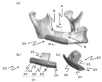
以下に、本発明の一実施形態として下顎骨の骨損傷部としての骨欠損部を有する部位に本発明に係る骨修復インプラントを設置する場合について図1を参照しながら説明する。具体的に、図1(a)は、下顎骨の一部が欠損した骨欠損部Aに本発明に係る骨修復インプラント10を設置した状態を示し、図1(b)、(c)はそれぞれ骨修復インプラント10の別方向を示す斜視図である。図1に示すように、骨修復インプラント10は、骨欠損部Aを有する骨(下顎骨)の表面形状に対応するように湾曲した板状に形成されている。具体的に、骨修復インプラント10は、骨欠損部Aを有する骨に設置される板状部11で構成されており、板状部11はその中央部12の両側に位置する接続部13に貫通孔14が設けられている。骨修復インプラント10は、中央部12が骨欠損部Aの一部を覆うように設置される。特に、本実施形態において、骨修復インプラント10は、中央部12が骨欠損部Aの下部を覆うように装着され、下方からその骨欠損部Aを有する骨を骨修復インプラント10が支持する。また、上述の通り、中央部12の両側に接続部13が配置されており、特に接続部13は骨欠損部Aの両側に位置する骨部分Bの表面形状に対応する表面形状を有しており、その部分に接する、好ましくは密接するように形成されている。また、上述の通り接続部13には貫通孔14が設けられているため、骨修復インプラント10の設置時にはスクリュー等の締結具をその貫通孔14に通し、接続部13と骨欠損部Aの両側に位置する骨部分Bとを締結する。これにより、骨修復インプラント10は、骨欠損部Aを有する骨に設置され、骨欠損部Aを有する骨が支持・固定されることとなる。なお、本実施形態に係る骨修復インプラント10において、板状部11の骨と接する側の面には、骨との結合を強固にするための生体活性処理が施されている。上述の通り、生体活性処理は、上記作用を付与できる処理であれば特に限定されないが、特に混酸加熱処理が好ましい。
The following describes, with reference to FIG. 1, a case where the bone repair implant according to the present invention is installed in a site having a bone defect as a bone damaged part of the mandible as an embodiment of the present invention. Specifically, FIG. 1(a) shows a state where the
また、上記実施形態の一変形例について図2を参照しながら説明する。図2に示すように、本変形例は上記実施形態に係る骨修復インプラントと比較して、板状部21の中央部22に人工骨部25が突設されていることを特徴とする。人工骨部25は、骨欠損部Aの形状に適合する形状に形成されている。従って、骨修復インプラント20を設置することにより、骨欠損部Aを人工骨部25により埋めることが可能となる。このような人工骨部25は、板状部21と同様に、患者の骨の三次元座標データに基づいて形成でき、例えば積層造形技術を用いることができる。このため、人工骨部25は板状部21と一体に形成することができる。また、人工骨部25は、多孔質構造であり、骨と接する面には、板状部21と同様に、骨との結合を強固にするための生体活性処理が施されている。上記実施形態と同様に、生体活性処理は、上記作用を付与できる処理であれば特に限定されないが、特に混酸加熱処理が好ましい。このような構成により、人工骨部25とその周囲の骨との一体化を促進することが可能となり、骨欠損部における骨修復を促進することができる。
A modified example of the above embodiment will be described with reference to FIG. 2. As shown in FIG. 2, this modified example is characterized in that an
人工骨部25は、上記の通り板状部21と一体に形成できる他に、別体として形成されてもよく、その場合、人工骨部25と板状部21とは例えばスクリュー等の締結具によって接続される。この場合、人工骨部25は板状部21と同様にチタン又はチタン合金を材料として用いることができ、人工骨部25の表面に生体活性処理が施されていることが好ましい。また、人工骨部25の表面のうち患者の骨と接触する部分については多孔チタンや粗面チタンからなることが好ましく、他の表面は平滑状であってよい。人工骨部25の内部構造については特に限定されないが、空洞であってもよいし、多孔構造であってもよい。人工骨部25の材料としては、上記のようなチタンの他に、例えばハイドロキシアパタイト等の生体活性セラミックを用いてもよい。表面に生体活性能を有する人工骨部25を用いることによって、人工骨部25が移植された骨欠損部Aの周囲の骨部分Bとの結合を促進できる。The
本実施形態において、上記板状部21及び人工骨部25は、骨欠損部Aの周囲の骨部分Bに相当する力学特性を有することが好ましい。このようにすると、骨欠損部Bとその周囲の骨部分Bとの間の力学特性の不連続性を低減することができ、板状部が骨欠損部Aの周囲の骨部分Bの動きに対して正常に共動できて、患者への負担を低減できる。In this embodiment, the plate-shaped
本実施形態において、人工骨部25は、図3(a)に示すように例えば略J字状(逆J字状)の板状部21の上に直接に設けられていてもよいし、この他に、図3(b)に示すように、板状部21の上に設けられた例えば板状部21と同等の材料からなる台座部21aの上に設けられてもよい。In this embodiment, the
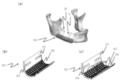
本実施形態の他の変形例として、図4に示すように板状部31は、少なくとも一部、例えば締結具が挿入される貫通孔が設けられる部分以外にメッシュ形状部分36を有していてもよい。患者の骨欠損部に板状部31を設置する際に、図4(c)に示すように板状部31に移植骨40を載置し、当該移植骨40により骨欠損部Aを補填する場合がある。この場合、板状部31の剛性が高いと、骨欠損部Aの周囲の骨にかかる負荷は板状部31に支持されて、移植骨40には負荷が作用しない応力遮蔽が生じてしまう。応力遮蔽とは、移植骨ではなくインプラント側に荷重が集中することで、移植骨に負荷がかからず、移植骨が骨吸収によって萎縮することを引き起こす原因となる現象である。図4に示すように、板状部31における移植骨40を載置する部分をメッシュ状にすることは、板状部31の剛性を低減できるため、上記応力遮蔽を防止できて好ましい。As another modification of this embodiment, as shown in FIG. 4, the plate-shaped
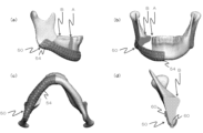
また、上記実施形態及び変形例では、下顎骨に設けられるインプラントを例示したが、図5に示すように、インプラントが下顎枝にまで及んでもよい。この場合、インプラントにおける下顎枝に及ぶ部分にも貫通孔が設けられており、下顎枝において締結具により締結できるように構成されていることが好ましい。In addition, while the above embodiment and modified example show an implant placed in the mandible, the implant may extend to the ramus as shown in Fig. 5. In this case, it is preferable that a through hole is provided in the portion of the implant that extends to the ramus, and that the implant is configured to be fastened by a fastener at the ramus.
さらに、本実施形態の他の変形例として、図6に示すように、骨修復インプラントは、複数の貫通孔を有する外形を有していてもよい。このようなインプラントについて、図6のように下顎骨の上方から設置する形態のものに限らず、図7に示すように、下顎骨の下方から設置する形態であってもよい。これらのような形状の場合、当該インプラントを締結具により骨に締結できる位置の自由度を向上でき、また、当該インプラントを骨欠損部に設置した状態においても、複数の貫通孔を介して骨欠損部を目視し易くなるため、術者の作業負担を低減できる。特に、図7に示す下顎骨の下方から設置されるインプラント50の場合、インプラント50の表面の全体にわたって複数の貫通孔54が形成されているため、上方を除く、下方、側方及び斜め方向等の最適な方向からスクリュー等の締結具60により骨に固定可能であるので、固定力の確保に極めて有利である。なお、本発明に係る骨修復インプラントは、上述の通り、患者の骨損傷部の三次元座標データに基づいて、例えば積層造形技術を用いて形成されるため、下顎骨に限らず、その他の種々の骨の骨損傷部に適用可能である。
As another modification of this embodiment, the bone repair implant may have an external shape with multiple through holes as shown in FIG. 6. Such an implant is not limited to the one installed from above the mandible as shown in FIG. 6, but may be installed from below the mandible as shown in FIG. 7. In the case of such a shape, the degree of freedom of the position at which the implant can be fastened to the bone by a fastener can be improved, and even when the implant is installed in the bone defect, the bone defect can be easily visually observed through the multiple through holes, so that the workload of the surgeon can be reduced. In particular, in the case of the
次に、本発明に係る骨修復インプラントの製造方法について説明する。本発明に係る骨修復インプラントの製造方法は、患者の骨損傷部を有する骨の三次元座標データを得るステップと、当該三次元座標データに基づいて、例えば積層造形技術や切削法等の技術を用いて、骨損傷部を有する骨の表面形状に対応する表面形状を少なくとも部分的に有し、且つ貫通孔を有する板状部を造形するステップを備えている。Next, a method for manufacturing the bone repair implant according to the present invention will be described. The method for manufacturing the bone repair implant according to the present invention includes the steps of obtaining three-dimensional coordinate data of a patient's bone having a bone damage area, and forming a plate-like portion having a through hole and at least partially having a surface shape corresponding to the surface shape of the bone having the bone damage area, using a technique such as additive manufacturing or cutting based on the three-dimensional coordinate data.
患者の骨損傷部を有する骨の三次元座標データを得るステップでは、まず、患者の骨損傷部を有する骨を例えばX線CTスキャン等のX線撮像技術を用いて撮影する。そして、その撮影画像をコンピュータにより画像解析ソフトを用いて三次元データを設計し、該三次元データが一定のピッチにスライスされて例えばSTLデータ等の三次元座標データを得る。In the step of obtaining three-dimensional coordinate data of a patient's bone having a bone injury, first, the patient's bone having a bone injury is photographed using X-ray imaging technology such as X-ray CT scan. The photographed image is then used by a computer to design three-dimensional data using image analysis software, and the three-dimensional data is sliced at a fixed pitch to obtain three-dimensional coordinate data such as STL data.
次に、得られた三次元座標データに基づいて、積層造形装置等を用い、チタン又はチタン合金粒子を材料としてインプラントを造形する。3Dプリンタを用いる場合、SLM(selective laser melting)法を利用した積層ピッチが小さいものを用いることが好ましく、例えばピッチは0.01mm~0.05mmであり、特にピッチが0.02mm~0.03mmであることが好ましい。このようにすることで、患者の骨損傷部を有する骨の表面形状に対応する表面形状を有するインプラントを正確且つ容易に製造することができる。また、小さいピッチで造形されることによりインプラントに多孔質構造にすることができ、このため、骨とインプラントが一体的に融合することができて互いの結合を強固にすることができる。Next, based on the obtained three-dimensional coordinate data, an implant is formed using titanium or titanium alloy particles as a material using an additive manufacturing device or the like. When using a 3D printer, it is preferable to use one with a small layer pitch using the SLM (selective laser melting) method, for example, a pitch of 0.01 mm to 0.05 mm, and particularly a pitch of 0.02 mm to 0.03 mm is preferable. In this way, an implant having a surface shape corresponding to the surface shape of the patient's bone having a bone injury can be accurately and easily manufactured. In addition, by forming with a small pitch, the implant can have a porous structure, and therefore the bone and the implant can be fused together to strengthen the bond between them.
この後に得られたインプラントに対して、特に患者の骨に接する面に対して生体活性処理を施すことが好ましい。生体活性処理は、当該インプラントと患者の骨との結合を強固にできるような処理であれば特に限定されないが、生体活性処理として混酸加熱処理を行うことが特に好ましい。用いる酸としては、塩酸、硫酸、硝酸及びフッ酸のうちの少なくとも2つ以上を含む混酸溶液を用いることが好ましい。これらの混酸溶液を用いることによって、当該インプラントに優れた骨形成能を発揮できる表面層を形成することができる。酸処理の方法は、上記混酸溶液にインプラントを浸漬するのが簡便でよく、浸漬時間は約1時間が好ましい。しかしながら、当然に混酸溶液をインプラントに接触できれば上記方法に限られない。また、酸処理は、インプラントのうち骨形成を促したい部位にのみ行うことがより好ましい。It is preferable to carry out a bioactivation treatment on the implant obtained after this, especially on the surface that contacts the patient's bone. The bioactivation treatment is not particularly limited as long as it is a treatment that can strengthen the bond between the implant and the patient's bone, but it is particularly preferable to carry out a mixed acid heat treatment as the bioactivation treatment. As the acid to be used, it is preferable to use a mixed acid solution containing at least two of hydrochloric acid, sulfuric acid, nitric acid, and hydrofluoric acid. By using these mixed acid solutions, a surface layer that can exhibit excellent bone formation ability can be formed on the implant. The method of acid treatment is simply to immerse the implant in the mixed acid solution, and the immersion time is preferably about 1 hour. However, the method is not limited to the above method as long as the mixed acid solution can be brought into contact with the implant. It is also more preferable to carry out the acid treatment only on the part of the implant where bone formation is desired to be promoted.
次に、インプラントに加熱処理を施す。その温度は、500℃~750℃が好ましく、その時間は1時間程度が好ましい。Next, the implant is subjected to a heat treatment, preferably at a temperature of 500°C to 750°C for about an hour.
さらに、本発明に係る製造方法において、上記の通り、当該インプラントに対して抗菌処理を施すステップを備えていてもよい。その処理方法については、特に限定されないが、上述したようなインプラントを銀、ガリウム、又はヨウ素等のイオン含有水溶液にインプラントを浸漬する方法等が挙げられる。Furthermore, the manufacturing method according to the present invention may include a step of subjecting the implant to an antibacterial treatment, as described above. The treatment method is not particularly limited, but may include a method of immersing the implant in an aqueous solution containing ions such as silver, gallium, or iodine.
上記工程により、簡便な方法で優れた骨形成能を有する本発明に係る骨修復インプラントを得ることができる。 The above process makes it possible to obtain the bone repair implant of the present invention, which has excellent bone formation ability, in a simple manner.
以下に、本発明に係る骨修復インプラント及びその製造方法を詳細に説明するための実施例を示す。本実施例では、上記方法により得られた骨修復インプラントが、酸処理や加熱処理が施されることにより、さらに優れた骨形成能を有することを説明する。 Below, we present examples to explain in detail the bone repair implant and its manufacturing method according to the present invention. In these examples, we explain that the bone repair implant obtained by the above method has even better bone formation ability when subjected to acid treatment and heat treatment.
(実施例1)
まず、上記方法により得られたチタン製インプラントを5つ準備し、それぞれに異なる条件の酸処理及び加熱処理を施した。具体的に、Group1では、塩酸と硫酸との混酸溶液を用いて酸処理を行い、600℃で1時間の加熱処理を施した。Group2では、NaOHによるアルカリ処理を行い、600℃で1時間の加熱処理を施した。Group3では、NaOH・50mM HClによる処理を行い、600℃で 1時間の加熱処理を施した。Group4では、NaOH・CaCl2による処理を行い、600℃で1時間の加熱処理及び80℃で24時間の温水処理を施した。Group5は無処理とした。
Example 1
First, five titanium implants obtained by the above method were prepared, and each was subjected to acid treatment and heat treatment under different conditions. Specifically, in
次に、骨欠損ラットを作成した。その方法は、図8に示すように、まず、麻酔を施したラットの頭部を切開し、骨膜を開けてラウンドバーにより骨欠損を作製した(図8(a)の写真)。続いて、上記のように作製されたインプラント(SLMメッシュ)を骨欠損部に適合させ、KLsマーチン1.0×8mmマイクロスクリューによって固定した(図8の(b)、(c)の写真)。その後、切開部を縫合した(図8の(d)の写真)。Next, rats with bone defects were created. As shown in Figure 8, the head of an anesthetized rat was first incised, the periosteum was opened, and a bone defect was created with a round bur (photograph in Figure 8(a)). Next, the implant (SLM mesh) created as described above was fitted to the bone defect and fixed with KLs Martin 1.0 x 8 mm microscrews (photographs in Figure 8(b) and (c)). The incision was then sutured (photograph in Figure 8(d)).
インプラントを設置して2週間後及び7週間後に、X線マイクロCTスキャナを用いて設置部位のX線写真を撮り、また、設置部位の非脱灰研磨標本を作製して、トリジンブルーで染色し、当該標本の写真を撮った。その結果を図9に示す。図9に示すように、インプラントを設置して2週間後、Group1~5のいずれにおいても、程度に差異はあるものの骨欠損部において設置されたインプラントの下部(図の破線で囲う領域)に新生骨の形成が認められた。特に、Group1において優れた新生骨の形成能が認められた(非脱灰研磨標本における矢印で示す濃いグレーで示す部分)。また、同様のことはインプラントを設置して7週間後においても認められ、また、Group1では、特に優れた新生骨の形成能が認められた。Two and seven weeks after the placement of the implants, X-rays of the placement sites were taken using an X-ray micro-CT scanner, and non-decalcified polished specimens of the placement sites were prepared and stained with tridine blue, and photographs of the specimens were taken. The results are shown in Figure 9. As shown in Figure 9, two weeks after the placement of the implants, new bone formation was observed in the lower part of the implants placed in the bone defect area (areas surrounded by dashed lines in the figure), although the degree varied, in all of
また、図10に各Groupにおけるインプラントを設置して2週間後及び7週間後の新生骨量を測定した結果を示す。新生骨量は、CT写真における面積比に基づいて算出した。図10に示すように、いずれのGroupにおいても設置から2週間後及び7週間後において、新生骨量が増加していたが、特にGroup1のインプラントが設置されたラットでは、新生骨量が他のGroupのインプラント設置されたラットよりも多いことが認められた。Figure 10 shows the results of measuring the
以上の結果から本発明に係るインプラントを用いることで、骨形成を促進することができ、特に、上記酸処理及び加熱処理を施したインプラントは、優れた骨形成能を示すことが明らかとなった。 The above results demonstrate that bone formation can be promoted by using the implant of the present invention, and in particular, the implant that has been subjected to the above-mentioned acid treatment and heat treatment exhibits excellent bone formation ability.
(実施例2)
次に、チタンからなるインプラントに抗菌処理が施されることにより、優れた抗菌性を付与できることを説明する。本実施例では、抗菌処理の一例として特にヨウ素処理による抗菌処理について説明する。
Example 2
Next, it will be described how an implant made of titanium can be given excellent antibacterial properties by being subjected to an antibacterial treatment. In this embodiment, an antibacterial treatment using iodine will be described as an example of the antibacterial treatment.
まず、純チタンからなる基材を#400のダイヤモンドパッドを用いて研磨し、アセトン、2-プロパノール及び超純水で各30分間超音波洗浄した後、5Mの水酸化ナトリウム水溶液5mlに60℃で24時間浸漬し(アルカリ処理)、超純水で30秒間洗浄した。このチタン板を100mMの塩化カルシウム水溶液10mlに40℃で24時間浸漬し(カルシウム処理)、超純水で30秒間洗浄した。次いで、チタン板を電気炉中で常温から600℃まで5℃/minの速度で昇温し、大気中600℃で1時間保持して、炉内で放冷した。その後、10mMの三塩化ヨウ素水溶液10mlに80℃で24時間浸漬し(ヨウ素処理)、超純水で30秒間洗浄することにより、試料Aを製造した。また、ヨウ素処理において、10mMの三塩化ヨウ素水溶液に代えて100mMの三塩化ヨウ素水溶液を用い、浸漬温度を60℃に変更して、その他の条件を上記試料Aの場合と同様にして、試料Bを製造した。また、上記処理のいずれも行わないチタン板を試料Cとした。First, a substrate made of pure titanium was polished using a #400 diamond pad, ultrasonically cleaned with acetone, 2-propanol, and ultrapure water for 30 minutes each, then immersed in 5 ml of 5M sodium hydroxide aqueous solution at 60°C for 24 hours (alkali treatment) and washed with ultrapure water for 30 seconds. This titanium plate was immersed in 10 ml of 100 mM calcium chloride aqueous solution at 40°C for 24 hours (calcium treatment) and washed with ultrapure water for 30 seconds. Next, the titanium plate was heated from room temperature to 600°C at a rate of 5°C/min in an electric furnace, held at 600°C in air for 1 hour, and allowed to cool in the furnace. After that, it was immersed in 10 ml of 10 mM iodine trichloride aqueous solution at 80°C for 24 hours (iodine treatment) and washed with ultrapure water for 30 seconds to produce sample A. In addition, in the iodine treatment, a 100 mM aqueous solution of iodine trichloride was used instead of the 10 mM aqueous solution of iodine trichloride, the immersion temperature was changed to 60° C., and the other conditions were the same as those of the above-mentioned sample A, to produce sample B. Sample C was a titanium plate that was not subjected to any of the above-mentioned treatments.
上記試料A~Cに対して、JIS Z 2801:2012の規定に準拠してメチシリン耐性黄色ブドウ球菌に対する抗菌性試験を行った。試験回数は繰り返し各2回とし、2回の平均コロニー数を算出した。なお、当初平均コロニー数は4.2×10⁴個/cm2であった。結果を表1に示す。また、抗菌効果の安定性を調べるために、試料A及び試料Bに対しては、80℃、相対湿度95%の環境下で1週間保持する耐湿試験と、リン酸緩衝生理食塩水中に36.5℃で50ストローク/分の速度で揺らしながら1週間保持する耐水試験を行った。それらの結果を表1に示す。The above samples A to C were subjected to an antibacterial test against methicillin-resistant Staphylococcus aureus in accordance with the provisions of JIS Z 2801:2012. Each test was repeated twice, and the average colony count for the two tests was calculated. The initial average colony count was 4.2 x 10⁴/cm2. The results are shown in Table 1. In addition, to examine the stability of the antibacterial effect, samples A and B were subjected to a moisture resistance test in which they were kept in an environment of 80°C and 95% relative humidity for one week, and a water resistance test in which they were kept in phosphate buffered saline at 36.5°C for one week while being rocked at a speed of 50 strokes/min. The results are shown in Table 1.

表1に示すように、未処理の試料Cと比較して、上記ヨウ素処理による抗菌処理が施された試料A及び試料Bでは、生菌数が0となり、強い抗菌性を示した。特に試料Aでは、耐湿試験及び耐水試験後でも強い抗菌性を示し、抗菌安定性に優れていることがわかった。As shown in Table 1, in comparison with untreated sample C, samples A and B, which were subjected to the antibacterial treatment using iodine, showed strong antibacterial properties, with the viable bacteria count being 0. In particular, sample A showed strong antibacterial properties even after the moisture resistance test and water resistance test, and was found to have excellent antibacterial stability.
次に、上記試料A及び試料Cに対して、JIS Z 2801:2012の規定に準拠して大腸菌に対する抗菌性試験を行った。なお、当初平均コロニー数は4.1×10³個/cm2であった。また、試料Aに対しては、上記耐湿試験及び耐水試験も行った。結果を表2に示す。Next, the above-mentioned samples A and C were subjected to an antibacterial test against E. coli in accordance with the provisions of JIS Z 2801:2012. The initial average colony count was 4.1 x 10³/cm2. Sample A was also subjected to the above-mentioned moisture resistance test and water resistance test. The results are shown in Table 2.
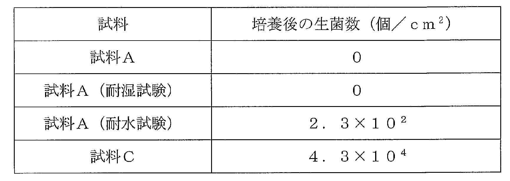
表2に示すように、当該試験においても未処理の試料Cと比較して、試料Aは強い抗菌性を示し、さらに、耐湿試験及び耐水試験後でも強い抗菌性を示し、抗菌安定性に優れていることがわかった。As shown in Table 2, in this test, sample A exhibited stronger antibacterial properties than the untreated sample C, and furthermore, it was found to exhibit stronger antibacterial properties even after the moisture resistance test and the water resistance test, demonstrating excellent antibacterial stability.
(実施例3)
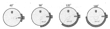
次に、本発明に係るインプラントにおいて、その形状(骨に対する設置範囲)を変化させた場合の荷重支持能力を、既存の数値シミュレーションソフトを用いて比較検討した。図11に示すように、下顎骨モデルとして直径20mmの平面視U字状で且つ一部に欠損部を有する形態とし、欠損部に板状インプラントを設置した状態とした。インプラントは、純チタン製であり厚み1.8mmとし、両端に直径3.1mmの2つの貫通孔をそれぞれに有するものとした。また、インプラントを締結するためのボルトも純チタン製とし呼び長さを12mm、呼び径を3.0mmとし、4本使用した。また、図11に示すように、下顎骨に荷重を与えるために剛球を採用した。また、シミュレーション時の拘束条件は、図11に示す拘束条件を採用した。さらに、本シミュレーションでは、インプラントと骨とが接している部分が結合している場合のモデルと結合していない場合のモデルとを比較して、インプラントに生体活性処理を施すことによる優位性について検討した。これに加えて、インプラントが骨を覆う範囲を変えて、発生する応力の増減について検討した。具体的には、図12に示すように、インプラントが骨を覆う範囲を40°、90°、135°、180°として、それぞれの応力を比較検討した。インプラントが骨を覆う範囲を40°とし、インプラントと骨とが結合していない場合の応力シミュレーション結果を図13に示す。図13に示すように、この場合では、インプラントの表側(骨と反対側)に最大で301MPa、インプラントの内側(骨側)に最大で300MPa、ボルトに最大で290MPaの応力がそれぞれ発生した。これと同様に他の条件で行った応力シミュレーションにおいて、発生した最大応力を以下の表3に示す。
Example 3
Next, the load-bearing capacity of the implant according to the present invention when its shape (the installation range relative to the bone) is changed was compared and examined using existing numerical simulation software. As shown in FIG. 11, the mandible model was a U-shaped mandible with a diameter of 20 mm in plan view, with a partial defect, and a plate-shaped implant was installed in the defect. The implant was made of pure titanium, had a thickness of 1.8 mm, and had two through holes with a diameter of 3.1 mm at both ends. In addition, the bolts for fastening the implant were also made of pure titanium, had a nominal length of 12 mm, a nominal diameter of 3.0 mm, and four bolts were used. In addition, as shown in FIG. 11, a hard ball was used to apply a load to the mandible. In addition, the constraint conditions during the simulation were as shown in FIG. 11. Furthermore, in this simulation, a model in which the part where the implant is in contact with the bone is bonded and a model in which it is not bonded were compared to examine the advantages of applying a bioactivation treatment to the implant. In addition, the range of the implant covering the bone was changed to examine the increase and decrease in the stress generated. Specifically, as shown in Fig. 12, the range in which the implant covers the bone was set to 40°, 90°, 135°, and 180°, and the stresses in each range were compared. Fig. 13 shows the results of a stress simulation in which the implant covers the bone at 40° and the implant is not bonded to the bone. As shown in Fig. 13, in this case, a maximum stress of 301 MPa was generated on the front side of the implant (opposite the bone), a maximum stress of 300 MPa was generated on the inside of the implant (the bone side), and a maximum stress of 290 MPa was generated on the bolt. In similar stress simulations performed under other conditions, the maximum stresses generated are shown in Table 3 below.

表3に示すように、数値シミュレーションの結果、インプラントについて骨を覆う範囲を大きくするに従って、インプラントに発生する応力を低減できることが明らかとなった。さらに、インプラント表面と骨表面とを結合させることにより、インプラントに発生する応力を低減できることが明らかとなった。この応力は覆う範囲を広くすることにより顕著に低くなる。この結果から、インプラントは、できるだけ骨を覆うような形態であることが好ましく、インプラントの骨と接する面に生体活性処理を施すことで、インプラントと骨との結合を促進させることが応力発生の観点からも有益であることが明らかとなった。 As shown in Table 3, the results of the numerical simulation revealed that the stress generated in the implant can be reduced as the area of bone coverage of the implant is increased. Furthermore, it was revealed that the stress generated in the implant can be reduced by bonding the implant surface to the bone surface. This stress is significantly reduced by increasing the area covered. From these results, it was revealed that it is preferable for the implant to be in a form that covers as much bone as possible, and that applying a bioactive treatment to the surface of the implant that comes into contact with the bone to promote bonding between the implant and the bone is also beneficial from the standpoint of stress generation.
Claims (16)
前記骨欠損部を有する骨の表面形状に対応する表面形状を少なくとも部分的に有し、且つ少なくとも部分的に前記骨の表面形状に沿ったトレイ状に湾曲した形状に形成された板状部を備え、
前記板状部のトレイ状の湾曲は、前記患者の前記骨欠損部を跨ぐように設置した場合に前記板状部における前記骨欠損部を跨ぐ方向に対して垂直な方向の断面形状がトレイ状に湾曲するものであり、
前記板状部は、該板状部に設けられた湾曲又は窪みによって構成された移植組織を設置するための空間をなす組織設置部を有し、
前記板状部には、該板状部を前記骨欠損部の周囲の骨部分に締結するための締結具が通ることができる貫通孔が設けられていることを特徴とする骨修復インプラント。 1. A bone repair implant comprising titanium or a titanium alloy for placement in a bone defect of a patient, comprising:
The bone defect portion has a surface shape that corresponds to the surface shape of the bone, and the plate-shaped portion is formed into a tray-like curved shape that at least partially follows the surface shape of the bone.
The tray-like curvature of the plate-shaped portion is such that, when the plate-shaped portion is placed so as to straddle the bone defect of the patient, the cross-sectional shape of the plate-shaped portion in a direction perpendicular to the direction of straddling the bone defect is curved into a tray shape,
The plate-shaped portion has a tissue placement portion that forms a space for placing a transplant tissue, the space being configured by a curve or a depression provided in the plate-shaped portion,
A bone repair implant, characterized in that the plate-shaped portion has a through hole through which a fastener can pass for fastening the plate-shaped portion to the bone portion surrounding the bone defect .
前記板状部が前記骨欠損部の下部を覆って、前記骨欠損部を有する骨を下方から支持するように該骨欠損部を有する骨に設置されるように構成されていることを特徴とする請求項2に記載の骨修復インプラント。 The plate-shaped portion has a surface shape corresponding to a surface shape of a lower portion of the bone having the bone defect ,
The bone repair implant according to claim 2, characterized in that the plate-shaped portion is configured to be placed on a bone having a bone defect so as to cover the lower portion of the bone defect and support the bone having the bone defect from below.
CT撮像技術を利用して患者の骨欠損部を有する骨の三次元座標データを得るステップと、
前記三次元座標データに基づいて、チタン又はチタン合金を材料として、前記積層造形装置が、前記骨欠損部を有する骨の表面形状に対応する表面形状を少なくとも部分的に有し、少なくとも部分的に前記骨の表面形状に沿ったトレイ状に湾曲した形状に形成され且つ貫通孔を有する板状部を造形するステップとを備え、
前記板状部のトレイ状の湾曲は、前記患者の前記骨欠損部を跨ぐように設置した場合に前記板状部における前記骨欠損部を跨ぐ方向に対して垂直な方向の断面形状がトレイ状に湾曲するものであり、
前記造形するステップにおいて、前記板状部に湾曲又は窪みを形成することで、移植組織を設置するための空間をなす組織設置部を有する形状に前記板状部を造形することを特徴とする骨修復インプラントの製造のための積層造形装置の作動方法。 1. A method of operating an additive manufacturing apparatus for the manufacture of a bone repair implant, comprising the steps of:
Obtaining three-dimensional coordinate data of a bone having a bone defect of a patient using a CT imaging technique;
and forming, by the additive manufacturing apparatus, a plate-shaped portion having a surface shape that at least partially corresponds to the surface shape of the bone having the bone defect portion, a tray-like curved shape that at least partially follows the surface shape of the bone, and a through hole, using titanium or a titanium alloy as a material based on the three-dimensional coordinate data;
The tray-like curvature of the plate-shaped portion is such that, when the plate-shaped portion is placed so as to straddle the bone defect of the patient, the cross-sectional shape of the plate-shaped portion in a direction perpendicular to the direction of straddling the bone defect is curved into a tray shape,
A method for operating an additive manufacturing device for manufacturing bone repair implants, characterized in that in the molding step, a curve or depression is formed in the plate-shaped portion to mold the plate-shaped portion into a shape having a tissue installation portion that forms a space for installing transplant tissue.
Applications Claiming Priority (3)
| Application Number | Priority Date | Filing Date | Title |
|---|---|---|---|
| JP2018149414 | 2018-08-08 | ||
| JP2018149414 | 2018-08-08 | ||
| PCT/JP2019/030631 WO2020031933A1 (en) | 2018-08-08 | 2019-08-05 | Bone repair implant and method for manufacturing same |
Publications (2)
| Publication Number | Publication Date |
|---|---|
| JPWO2020031933A1 JPWO2020031933A1 (en) | 2021-08-26 |
| JP7533859B2 true JP7533859B2 (en) | 2024-08-14 |
Family
ID=69415009
Family Applications (1)
| Application Number | Title | Priority Date | Filing Date |
|---|---|---|---|
| JP2020535746A Active JP7533859B2 (en) | 2018-08-08 | 2019-08-05 | Bone repair implant and method of manufacturing same |
Country Status (2)
| Country | Link |
|---|---|
| JP (1) | JP7533859B2 (en) |
| WO (1) | WO2020031933A1 (en) |
Families Citing this family (1)
| Publication number | Priority date | Publication date | Assignee | Title |
|---|---|---|---|---|
| SE547315C2 (en) * | 2023-07-13 | 2025-07-01 | Medcer Ab | Device for reconstruction of bone defects |
Citations (6)
| Publication number | Priority date | Publication date | Assignee | Title |
|---|---|---|---|---|
| JP2005512702A (en) | 2001-12-12 | 2005-05-12 | テコメット インコーポレイテッド | Textured surface with undercut fine depressions on the surface |
| JP2009501575A (en) | 2005-07-13 | 2009-01-22 | アキュームド・エルエルシー | Bone plate with movable locking element |
| US20110035024A1 (en) | 2009-08-10 | 2011-02-10 | Osseous Technologies Of America | Self-Supporting Collagen Tunnel for Guided Tissue Regeneration and Method of Using Same |
| CN203988499U (en) | 2014-08-08 | 2014-12-10 | 上海交通大学医学院附属第九人民医院 | The net bag type mandibular bone implants of applying three-dimensional printing technique |
| CN107157566A (en) | 2017-06-20 | 2017-09-15 | 上海交通大学医学院附属第九人民医院 | It is a kind of that there is the defect fracture of mandible reconstruction titanium plate part for aiding in bone grafting function |
| JP2017536160A (en) | 2014-10-22 | 2017-12-07 | バイオメット シー.ブイ. | Bone fixation device |
Family Cites Families (4)
| Publication number | Priority date | Publication date | Assignee | Title |
|---|---|---|---|---|
| US4608052A (en) * | 1984-04-25 | 1986-08-26 | Minnesota Mining And Manufacturing Company | Implant with attachment surface |
| CN1156255C (en) * | 1993-10-01 | 2004-07-07 | 美商-艾克罗米德公司 | Spinal implant |
| US5769637A (en) * | 1996-05-22 | 1998-06-23 | Sofamor Danek Properties, Inc. | Dental implant and alveolar process augmentation structures and method of installation |
| US6712851B1 (en) * | 1998-01-23 | 2004-03-30 | Macropore Biosurgery, Inc. | Resorbable, macro-porous non-collapsing and flexible membrane barrier for skeletal repair and regeneration |
-
2019
- 2019-08-05 WO PCT/JP2019/030631 patent/WO2020031933A1/en not_active Ceased
- 2019-08-05 JP JP2020535746A patent/JP7533859B2/en active Active
Patent Citations (6)
| Publication number | Priority date | Publication date | Assignee | Title |
|---|---|---|---|---|
| JP2005512702A (en) | 2001-12-12 | 2005-05-12 | テコメット インコーポレイテッド | Textured surface with undercut fine depressions on the surface |
| JP2009501575A (en) | 2005-07-13 | 2009-01-22 | アキュームド・エルエルシー | Bone plate with movable locking element |
| US20110035024A1 (en) | 2009-08-10 | 2011-02-10 | Osseous Technologies Of America | Self-Supporting Collagen Tunnel for Guided Tissue Regeneration and Method of Using Same |
| CN203988499U (en) | 2014-08-08 | 2014-12-10 | 上海交通大学医学院附属第九人民医院 | The net bag type mandibular bone implants of applying three-dimensional printing technique |
| JP2017536160A (en) | 2014-10-22 | 2017-12-07 | バイオメット シー.ブイ. | Bone fixation device |
| CN107157566A (en) | 2017-06-20 | 2017-09-15 | 上海交通大学医学院附属第九人民医院 | It is a kind of that there is the defect fracture of mandible reconstruction titanium plate part for aiding in bone grafting function |
Also Published As
| Publication number | Publication date |
|---|---|
| JPWO2020031933A1 (en) | 2021-08-26 |
| WO2020031933A1 (en) | 2020-02-13 |
Similar Documents
| Publication | Publication Date | Title |
|---|---|---|
| Tu et al. | 3D laser-printed porous Ti6Al4V dental implants for compromised bone support | |
| Wang et al. | " Sandwich" bone augmentation technique: rationale and report of pilot cases. | |
| Fukuda et al. | Bone bonding bioactivity of Ti metal and Ti–Zr–Nb–Ta alloys with Ca ions incorporated on their surfaces by simple chemical and heat treatments | |
| Ellis et al. | Use of nonresorbable alloplastic implants for internal orbital reconstruction | |
| Sevin et al. | Exposure of high-density porous polyethylene (Medpor®) used for contour restoration and treatment | |
| Shi et al. | Customized barrier membrane (titanium alloy, poly ether-ether ketone and Unsintered hydroxyapatite/poly-l-Lactide) for guided bone regeneration | |
| Uezono et al. | Hydroxyapatite/collagen nanocomposite‐coated titanium rod for achieving rapid osseointegration onto bone surface | |
| US20040010313A1 (en) | Porous and/or polycrystalline silicon orthopaedic implant | |
| US20090283701A1 (en) | Medical Implants | |
| Kanno et al. | Computed tomographic evaluation of novel custom-made artificial bones,“CT-bone”, applied for maxillofacial reconstruction | |
| Dau et al. | Bone formation in mono cortical mandibular critical size defects after augmentation with two synthetic nanostructured and one xenogenous hydroxyapatite bone substitute–in vivo animal study | |
| AU2001274217A1 (en) | A porous and/or polycrystalline silicon orthopaedic implant | |
| WO2015138657A1 (en) | Methods, devices, and manufacture of the devices for musculoskeletal reconstructive surgery | |
| Kamboj et al. | Novel silicon-wollastonite based scaffolds for bone tissue engineering produced by selective laser melting | |
| Byun et al. | The bioresorption and guided bone regeneration of absorbable hydroxyapatite-coated magnesium mesh | |
| Moiduddin et al. | Customized porous implants by additive manufacturing for zygomatic reconstruction | |
| Papacharalambous et al. | Natural coral skeleton used as on lay graft for contour augmentation of the face. A preliminary report | |
| JP7533859B2 (en) | Bone repair implant and method of manufacturing same | |
| Saijo et al. | Clinical experience of full custom-made artificial bones for the maxillofacial region | |
| Tian et al. | In vivo study of the early bone-bonding ability of Ti meshes formed with calcium titanate via chemical treatments | |
| Von Wilmonsky et al. | In vivo evaluation of ß-TCP containing 3D laser sintered poly (ether ether ketone) composites in pigs | |
| Li et al. | Applicative assessment of a selective laser melting 3D-printed Ti–6Al–4 V plate with a honeycomb structure in the reconstruction of a mandibular defect of a beagle dog | |
| US20180228513A1 (en) | Method for producing an occlusive barrier for bone regeneration and an occlusive barrier obtained by means of said method | |
| Yamamoto et al. | Osteogenic capacity of mixed-acid and heat-treated titanium mesh prepared by a selective laser melting technique | |
| CN103690274B (en) | Bone lacks prosthetic device |
Legal Events
| Date | Code | Title | Description |
|---|---|---|---|
| A621 | Written request for application examination |
Free format text: JAPANESE INTERMEDIATE CODE: A621 Effective date: 20220606 |
|
| A131 | Notification of reasons for refusal |
Free format text: JAPANESE INTERMEDIATE CODE: A131 Effective date: 20230425 |
|
| A521 | Request for written amendment filed |
Free format text: JAPANESE INTERMEDIATE CODE: A523 Effective date: 20230614 |
|
| A131 | Notification of reasons for refusal |
Free format text: JAPANESE INTERMEDIATE CODE: A131 Effective date: 20231003 |
|
| A521 | Request for written amendment filed |
Free format text: JAPANESE INTERMEDIATE CODE: A523 Effective date: 20231121 |
|
| A131 | Notification of reasons for refusal |
Free format text: JAPANESE INTERMEDIATE CODE: A131 Effective date: 20240305 |
|
| A521 | Request for written amendment filed |
Free format text: JAPANESE INTERMEDIATE CODE: A523 Effective date: 20240501 |
|
| TRDD | Decision of grant or rejection written | ||
| A01 | Written decision to grant a patent or to grant a registration (utility model) |
Free format text: JAPANESE INTERMEDIATE CODE: A01 Effective date: 20240716 |
|
| A61 | First payment of annual fees (during grant procedure) |
Free format text: JAPANESE INTERMEDIATE CODE: A61 Effective date: 20240722 |
|
| R150 | Certificate of patent or registration of utility model |
Ref document number: 7533859 Country of ref document: JP Free format text: JAPANESE INTERMEDIATE CODE: R150 |