JP7532002B2 - Transport conveyor and V-shaped transport mechanism equipped with same - Google Patents
Transport conveyor and V-shaped transport mechanism equipped with same Download PDFInfo
- Publication number
- JP7532002B2 JP7532002B2 JP2023543500A JP2023543500A JP7532002B2 JP 7532002 B2 JP7532002 B2 JP 7532002B2 JP 2023543500 A JP2023543500 A JP 2023543500A JP 2023543500 A JP2023543500 A JP 2023543500A JP 7532002 B2 JP7532002 B2 JP 7532002B2
- Authority
- JP
- Japan
- Prior art keywords
- frame
- pulley
- offset
- conveyor
- transport
- Prior art date
- Legal status (The legal status is an assumption and is not a legal conclusion. Google has not performed a legal analysis and makes no representation as to the accuracy of the status listed.)
- Active
Links
Images


Classifications
-
- B—PERFORMING OPERATIONS; TRANSPORTING
- B65—CONVEYING; PACKING; STORING; HANDLING THIN OR FILAMENTARY MATERIAL
- B65G—TRANSPORT OR STORAGE DEVICES, e.g. CONVEYORS FOR LOADING OR TIPPING, SHOP CONVEYOR SYSTEMS OR PNEUMATIC TUBE CONVEYORS
- B65G23/00—Driving gear for endless conveyors; Belt- or chain-tensioning arrangements
- B65G23/02—Belt- or chain-engaging elements
- B65G23/04—Drums, rollers, or wheels
-
- B—PERFORMING OPERATIONS; TRANSPORTING
- B65—CONVEYING; PACKING; STORING; HANDLING THIN OR FILAMENTARY MATERIAL
- B65G—TRANSPORT OR STORAGE DEVICES, e.g. CONVEYORS FOR LOADING OR TIPPING, SHOP CONVEYOR SYSTEMS OR PNEUMATIC TUBE CONVEYORS
- B65G23/00—Driving gear for endless conveyors; Belt- or chain-tensioning arrangements
- B65G23/44—Belt or chain tensioning arrangements
-
- B—PERFORMING OPERATIONS; TRANSPORTING
- B65—CONVEYING; PACKING; STORING; HANDLING THIN OR FILAMENTARY MATERIAL
- B65G—TRANSPORT OR STORAGE DEVICES, e.g. CONVEYORS FOR LOADING OR TIPPING, SHOP CONVEYOR SYSTEMS OR PNEUMATIC TUBE CONVEYORS
- B65G39/00—Rollers, e.g. drive rollers, or arrangements thereof incorporated in roller-ways or other types of mechanical conveyors
- B65G39/02—Adaptations of individual rollers and supports therefor
- B65G39/04—Adaptations of individual rollers and supports therefor the rollers comprising a number of roller forming elements mounted on a single axle
-
- B—PERFORMING OPERATIONS; TRANSPORTING
- B65—CONVEYING; PACKING; STORING; HANDLING THIN OR FILAMENTARY MATERIAL
- B65G—TRANSPORT OR STORAGE DEVICES, e.g. CONVEYORS FOR LOADING OR TIPPING, SHOP CONVEYOR SYSTEMS OR PNEUMATIC TUBE CONVEYORS
- B65G39/00—Rollers, e.g. drive rollers, or arrangements thereof incorporated in roller-ways or other types of mechanical conveyors
- B65G39/10—Arrangements of rollers
- B65G39/12—Arrangements of rollers mounted on framework
Landscapes
- Engineering & Computer Science (AREA)
- Mechanical Engineering (AREA)
- Structure Of Belt Conveyors (AREA)
Description
本発明は、搬送コンベヤおよびそれを備えたV字搬送機構に関する。 The present invention relates to a transport conveyor and a V-shaped transport mechanism equipped with the same.
被計量物を目的の重量に計量する組合せ秤が知られている。組合せ秤には、被計量物を搬送するための搬送コンベヤを用いた搬送機構が設けられる場合がある。 Combination weighers are known that weigh an object to a desired weight. Some combination weighers are equipped with a transport mechanism that uses a transport conveyor to transport the object.
例えば、下記特許文献1には、計量前の被計量物をホッパに搬送するための搬送機構として搬送方向に2条のベルト(搬送コンベヤ)を並列させ、それらがV字になるように配設された構成が開示されている。For example, the following
また、下記特許文献2には、被計量物の供給が人手によって行われ、被計量物の排出が自動で行われる半自動式の組合せ秤において、ホッパから排出された被計量物を搬送するための搬送機構として、2つの搬送コンベヤを搬送方向から見て搬送面がV字状となるように並列に配設した構成が開示されている。Furthermore, the following
しかし、従来の搬送コンベヤを用いた搬送機構には、改善すべき点がある。搬送コンベヤは、シャフトに対してベアリングを介して回転可能に構成される駆動プーリおよび従動プーリと、これらのプーリに巻き回される搬送ベルトと、駆動プーリおよび従動プーリのシャフトを支持する左右一対のフレームとを備えている。駆動プーリおよび従動プーリは、一対のフレーム間に設けられる。一般的な搬送コンベヤでは、搬送ベルトのベルト幅に対応する軸方向長さを有するプーリが用いられるため、一対のフレームは、搬送ベルトの幅方向両端部より幅方向外側に位置することになる。However, there are areas that need improvement in the transport mechanism using conventional transport conveyors. The transport conveyor includes a drive pulley and a driven pulley that are configured to rotate on a shaft via bearings, a transport belt that is wound around these pulleys, and a pair of left and right frames that support the shafts of the drive pulley and the driven pulley. The drive pulley and the driven pulley are provided between the pair of frames. In a typical transport conveyor, a pulley that has an axial length that corresponds to the belt width of the transport belt is used, so the pair of frames are positioned widthwise outboard of both widthwise ends of the transport belt.
このような搬送コンベヤにおいては、搬送ベルトの幅方向両端部からプーリとフレームとの隙間に被計量物の屑や塵等が入り込む恐れがある。特に、上記特許文献1,2のようなV字搬送機構においては、搬送ベルトの幅方向において下方に位置する端部側に屑や塵等が入り込み易くなる。被計量物が食品等である場合にプーリとフレームとの隙間に屑や塵等が入り込むと不衛生である。また、プーリとフレームとの隙間に入り込んだ屑や塵等が堆積すると、これらがベアリングに接触した状態となり、ベアリングが損傷する、または、プーリの回転が阻害される等の問題が生じ得る。したがって、従来の搬送コンベヤを用いた被計量物の搬送機構においては、メンテナンスの頻度を低減することについて改善の余地がある。In such a transport conveyor, there is a risk that debris or dust from the weighed objects may get into the gap between the pulley and the frame from both ends of the conveyor belt in the width direction. In particular, in a V-shaped transport mechanism such as those described in
そこで本発明は、メンテナンスの頻度を低減することができる搬送コンベヤおよびそれを備えたV字搬送機構を提供することを目的とする。 Therefore, the present invention aims to provide a transport conveyor that can reduce the frequency of maintenance and a V-shaped transport mechanism equipped with the same.
本発明の一態様に係る搬送コンベヤは、第1回転軸回りに回転する第1プーリと、第2回転軸回りに回転する第2プーリと、前記第1回転軸および前記第2回転軸を支持する一対のフレームと、前記第1プーリおよび前記第2プーリの間に巻き回された搬送ベルトと、を備え、前記一対のフレームのうちの少なくとも一方のフレームは、前記搬送ベルトの幅方向両端部よりも内側で前記第1回転軸および前記第2回転軸を支持するオフセット支持部を有するオフセットフレームとして構成される。 A transport conveyor according to one embodiment of the present invention comprises a first pulley that rotates around a first rotation axis, a second pulley that rotates around a second rotation axis, a pair of frames that support the first and second rotation axes, and a transport belt wound between the first and second pulleys, and at least one of the pair of frames is configured as an offset frame having an offset support portion that supports the first and second rotation axes inside both widthwise ends of the transport belt.
上記構成によれば、オフセットフレームのオフセット支持部において搬送ベルトの幅方向両端部よりも内側にフレームとプーリとの隙間が位置するため、搬送ベルトの幅方向におけるオフセットフレーム側の端部から屑や塵等が落下したとしても当該隙間にそれらが入ることを防止することができる。したがって、搬送コンベヤを衛生的に保持するとともにプーリの滑らかな回転が維持される。これにより、メンテナンスの頻度を低減することができる。 According to the above configuration, the gap between the frame and the pulley is located inside both ends of the conveyor belt in the width direction at the offset support part of the offset frame, so that even if debris or dust falls from the end of the conveyor belt in the width direction on the offset frame side, it is possible to prevent them from entering the gap. This keeps the conveyor hygienic and maintains the smooth rotation of the pulley. This reduces the frequency of maintenance.
前記一対のフレームは、前記第1回転軸および前記第2回転軸に直交する外表面をそれぞれ有する一対のフレーム本体と、前記フレーム本体に接続され、前記第1プーリと前記第2プーリとの間の距離を調整することにより前記搬送ベルトの張力を調整する一対の張力調整部と、を含み、前記一対の張力調整部は、前記搬送ベルトの幅方向に関して前記一対のフレーム本体の前記外表面より外側にそれぞれ設けられ、前記一対の張力調整部のうち、前記オフセットフレーム側に設けられる張力調整部は、前記オフセット支持部と前記搬送ベルトの幅方向における前記オフセットフレーム側の端部との間に位置してもよい。The pair of frames includes a pair of frame bodies each having an outer surface perpendicular to the first rotation axis and the second rotation axis, and a pair of tension adjustment units connected to the frame bodies and adjusting the tension of the conveying belt by adjusting the distance between the first pulley and the second pulley, the pair of tension adjustment units being respectively provided outside the outer surfaces of the pair of frame bodies in the width direction of the conveying belt, and of the pair of tension adjustment units, the tension adjustment unit provided on the offset frame side may be located between the offset support part and the end of the conveying belt on the offset frame side in the width direction.
上記構成によれば、オフセットフレーム側において搬送ベルトの幅方向両端部よりも内側に張力調整部が位置する。そのため、2つの搬送コンベヤをV字に配置してV字搬送機構を構成する場合等において、オフセットフレーム側がV字の谷間(中央部)に位置するように2つの搬送コンベヤを配設することにより、2つの搬送ベルト間の隙間を小さくすることができる。これにより、搬送ベルト間の隙間から被計量物またはその屑等が落下するのを抑制することができる。 According to the above configuration, the tension adjustment unit is located on the offset frame side, inside both ends of the width direction of the conveyor belt. Therefore, when two conveyors are arranged in a V shape to form a V-shaped conveyor mechanism, the gap between the two conveyor belts can be reduced by arranging the two conveyors so that the offset frame side is located in the valley (center) of the V shape. This makes it possible to prevent the objects to be weighed or their debris from falling through the gap between the conveyor belts.
前記一対のフレームは、前記第1回転軸および前記第2回転軸に直交する外表面をそれぞれ有する一対のフレーム本体を含み、前記第1プーリおよび前記第2プーリは、それぞれ、前記一対のフレーム本体間に配設された主プーリと、前記搬送ベルトの幅方向に関して前記オフセットフレームにおける前記オフセット支持部より外側に配設された補助プーリと、を含んでもよい。The pair of frames may include a pair of frame bodies each having an outer surface perpendicular to the first rotation axis and the second rotation axis, and the first pulley and the second pulley may each include a main pulley arranged between the pair of frame bodies and an auxiliary pulley arranged outside the offset support portion in the offset frame in the width direction of the conveying belt.
上記構成によれば、オフセットフレームにおけるオフセット支持部より外側に補助プーリが配設される。これにより、一対のフレームのうちの少なくとも一方における回転軸の支持位置を搬送ベルトの幅方向両端部より内側に位置させつつ、搬送ベルトの幅方向両端部においてプーリを搬送ベルトに接触させることができる。これにより、搬送ベルトの幅方向における主プーリのオフセットフレーム側の端部(すなわち、搬送ベルトの幅方向両端部より内側)において搬送ベルトに過剰な張力が生じることを防止し、これによる搬送ベルトの劣化を抑制することができる。 According to the above configuration, the auxiliary pulley is disposed outside the offset support portion of the offset frame. This allows the support position of the rotating shaft in at least one of the pair of frames to be located inside both ends of the width of the conveyor belt, while the pulley can be brought into contact with the conveyor belt at both ends of the width of the conveyor belt. This prevents excessive tension from being generated in the conveyor belt at the end of the main pulley on the offset frame side in the width direction of the conveyor belt (i.e., inside both ends of the width of the conveyor belt), and thereby suppresses deterioration of the conveyor belt.
本発明の他の態様に係るV字搬送機構は、搬送方向から見て搬送面がV字状になるように2つの搬送コンベヤが配置されたV字搬送機構であって、前記2つの搬送コンベヤは、それぞれ、上記構成の搬送コンベヤであり、前記オフセットフレームが他方のフレームに対して下方に位置するように、前記第1回転軸および前記第2回転軸が傾斜して配置されている。 A V-shaped conveying mechanism according to another aspect of the present invention is a V-shaped conveying mechanism in which two conveying conveyors are arranged so that the conveying surface is V-shaped when viewed from the conveying direction, and each of the two conveying conveyors is a conveying conveyor having the above-described configuration, and the first rotating shaft and the second rotating shaft are arranged at an incline so that the offset frame is positioned lower relative to the other frame.
上記構成によれば、2つの搬送コンベヤのそれぞれについて、オフセットフレーム側が下方に位置するように配設されるため、搬送ベルトの幅方向におけるオフセットフレーム側の端部から被計量物の屑や塵等が落下しても、オフセットフレームとプーリとの隙間に屑や塵等が入ることを防止することができる。したがって、搬送コンベヤを衛生的に保持するとともにプーリの滑らかな回転が維持される。これにより、メンテナンスの頻度を低減することができる。また、オフセットフレームと搬送ベルトの幅方向におけるオフセットフレーム側の端部との間に搬送ベルトの張力を調整する張力調整部を配置可能になるため、2つの搬送ベルト間の隙間を小さくすることができる。これにより、2つの搬送ベルト間の隙間から被計量物またはその屑等が落下するのを抑制することができる。 According to the above configuration, the offset frame side of each of the two conveyors is disposed at the bottom, so that even if debris or dust from the weighed objects falls from the end of the offset frame side in the width direction of the conveyor belt, the debris or dust can be prevented from entering the gap between the offset frame and the pulley. Therefore, the conveyor is kept hygienic and the smooth rotation of the pulley is maintained. This reduces the frequency of maintenance. In addition, a tension adjustment unit that adjusts the tension of the conveyor belt can be disposed between the offset frame and the end of the conveyor belt on the offset frame side in the width direction, so that the gap between the two conveyor belts can be reduced. This makes it possible to prevent the weighed objects or debris from falling through the gap between the two conveyor belts.
前記2つの搬送コンベヤのうちの一方の搬送コンベヤは、前記搬送ベルトの幅方向における前記オフセットフレーム側の端部が前記2つの搬送コンベヤのうちの他方の搬送コンベヤの前記搬送ベルト上に位置するように、配置されていてもよい。One of the two conveying conveyors may be positioned so that the end of the conveying belt on the offset frame side in the width direction is positioned on the conveying belt of the other of the two conveying conveyors.
上記構成によれば、2つの搬送ベルト間の隙間をより小さくすることができる。 With the above configuration, the gap between the two conveying belts can be made smaller.
本発明によれば、搬送コンベヤおよびそれを備えたV字搬送機構において、メンテナンスの頻度を低減することができる。 According to the present invention, the frequency of maintenance can be reduced in a transport conveyor and a V-shaped transport mechanism equipped with the same.
以下、本発明の一実施の形態に係る搬送コンベヤおよびそれを備えたV字搬送機構について説明する。本実施の形態においては、V字搬送機構が設けられた半自動式の組合せ秤を例示する。図1~図3に示すように、本実施の形態における組合せ秤は、複数の計量部Cw1~Cw12と、V字搬送機構3と、操作設定表示器4と、制御装置5等を備えている。
Below, a transport conveyor and a V-shaped transport mechanism equipped with the same according to one embodiment of the present invention will be described. In this embodiment, a semi-automatic combination weigher equipped with a V-shaped transport mechanism is exemplified. As shown in Figures 1 to 3, the combination weigher in this embodiment includes multiple weighing sections Cw1 to Cw12, a V-
複数の計量部Cw1~Cw12の各々は、ベルトコンベヤで構成される計量コンベヤ1と、計量コンベヤ1を支持するロードセル等からなり、計量コンベヤ1上の被計量物の重量を計量する重量センサ2とを備えている。各計量コンベヤ1には、被計量物が計量コンベヤ1の両サイドから落ちないように一対のガイド板11が配設されている。具体的には、例えば、図3に示すように、ガイド板11はコンベヤフレーム1Fに取り付けられている。また、各計量コンベヤ1のコンベヤフレーム1Fの下面には計量コンベヤ1の駆動モータ1Mが取り付けられている。また、重量センサ2は装置本体部22内で図示されない固定部材に固定され、その上部に取付部材を介してコンベヤフレーム1Fが取り付けられている。すなわち、重量センサ2は、一対のガイド板11および駆動モータ1Mを含む計量コンベヤ1を支持している。なお、本実施の形態では、計量コンベヤ1と重量センサ2とを区別しているが、両者を含めた装置を計量コンベヤと称する場合もある。Each of the weighing units Cw1 to Cw12 is equipped with a weighing
6個の計量部Cw1~Cw6と、他の6個の計量部Cw7~Cw12との間に、2つの搬送コンベヤ3a,3bを含むV字搬送機構3が配設されている。計量部Cw1~Cw6の6個の計量コンベヤ1は、V字搬送機構3の一方の側方において並行に配置され、これら各々の搬送方向(矢印aの方向)がV字搬送機構3の搬送方向(矢印cの方向)と直交するように配置されている。また、計量部Cw7~Cw12の6個の計量コンベヤ1は、V字搬送機構3の他方の側方において並行に配置され、これら各々の搬送方向(矢印bの方向)がV字搬送機構3の搬送方向(矢印cの方向)と直交するように配置されている。Between the six weighing units Cw1 to Cw6 and the other six weighing units Cw7 to Cw12, a V-
V字搬送機構3は、図3に示すように、無端の搬送ベルトを有する2つの搬送コンベヤ3a,3bを、搬送方向から見てその搬送面がV字状となるように並行に配設されて構成されている。これら2つの搬送コンベヤ3a,3bは、搬送速度が同一に設定されており、ここでは矢印cの方向を搬送方向とする。これら2つの搬送コンベヤ3a,3b間の隙間3sの下方には、隙間3sから落ちる屑や塵等を受けて溜めるためのトレー13が置かれている。このトレー13を引きだして溜まったごみ等を捨てることができる。2つの搬送コンベヤ3a,3bの搬送面のなす角度は、特に限定されないが、例えば90度程度である。この角度は調整可能であってもよい。As shown in FIG. 3, the V-
本実施の形態では、V字搬送機構3は、矢印cの方向へ被計量物を搬送し、その搬送方向下流側端部から被計量物を排出する。V字搬送機構3の搬送方向下流側の端部には、後段装置が設置され、V字搬送機構3によって搬送された被計量物は、後段装置へ供給される。In this embodiment, the V-
装置本体部22は架台21上に取り付けられ、装置本体部22上にV字搬送機構3が取り付けられている。なお、搬送コンベヤ3a,3bの取付支持部材および駆動モータは、図示を省略している。また、装置本体部22の側方には支持部材23が取り付けられ、支持部材23に支柱24を介して操作設定表示器4が取り付けられている。The device
各計量コンベヤ1を支持する重量センサ2によって計量コンベヤ1上の被計量物の重量が計量され、その計量値(アナログ重量信号)は、A/D変換されて制御装置5に送られる。制御装置5は、例えばマイクロコントローラ等によって構成され、CPU等からなる演算制御部と、RAMおよびROM等のメモリとを有している。メモリには、運転用プログラム、動作パラメータのデータ、計量データ等が記憶される。制御装置5は、演算制御部がメモリに記憶されている運転用プログラムを実行することにより、組合せ秤の全体の制御および組合せ演算処理等を行う。The weight of the objects to be weighed on the weighing
以下、搬送コンベヤ3aについてより詳しく説明する。なお、搬送コンベヤ3bは、搬送コンベヤ3aと搬送方向に沿った仮想線V1を基準とする線対称に構成される(幅方向に反転した構造を有する)。The
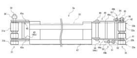
図4に示すように、搬送コンベヤ3aは、第1プーリ31、第2プーリ32、一対のフレーム41,42および搬送ベルト33を備えている。第1プーリ31は、第1回転軸34回りに回転する駆動側プーリである。第2プーリ32は、第2回転軸35回りに回転する従動側プーリである。一対のフレーム41,42は、第1回転軸34および第2回転軸35に直交する方向(搬送ベルト33の搬送方向)に延び、第1回転軸34および第2回転軸35を支持する。
As shown in Figure 4, the
一対のフレームは、第1フレーム41および第2フレーム42を含む。第1フレーム41は、第1回転軸34を支持する第1駆動側フレーム43と、第2回転軸35を支持する第1従動側フレーム44とを有する。第2フレーム42は、第1フレーム41と同様に、第1回転軸34を支持する第2駆動側フレーム45と、第2回転軸35を支持する第2従動側フレーム46とを有する。各フレーム43,44,45,46は、それぞれ、第1回転軸34および第2回転軸35に直交する外表面をそれぞれ有する一対のフレーム本体43a,44a,45a,46aを有する。The pair of frames includes a
第1駆動側フレーム43および第2駆動側フレーム45と、第1従動側フレーム44および第2従動側フレーム46とは、フレーム接続部47を介して接続されている。駆動側フレーム43,45とフレーム接続部47とは、固定的に接続される。従動側フレーム44,46とフレーム接続部47とは、第1回転軸34および第2回転軸35に平行に配設された回動軸48を介して接続される。これにより、従動側フレーム44,46は、駆動側フレーム43,45およびフレーム接続部47に対して回動軸48回りに回動可能である。これにより、駆動側フレーム43,45(すなわち、搬送ベルト33の駆動機構側)を装置本体部22に設置した状態で、従動側フレーム44,46を回動軸48回りに回動させて、後述する張力調整部44b,46bを露出させることができる。これにより、後述する張力調整部44b,46bを用いた搬送ベルト33の張力調整を行い易くすることができる。The first
第1駆動側フレーム43と第2駆動側フレーム45との間には、第1プーリ31(後述する第1主プーリ31a)が配設される。第1プーリ31は、第1回転軸34に固定され、第1回転軸34が中心軸線回りに回転することにより、第1プーリ31は第1回転軸34回りに回転する。図示しない駆動モータからの駆動力が第1回転軸34に設けられた動力伝達部36に伝達することにより、第1回転軸34は中心軸線回りに回転する。A first pulley 31 (first
第1従動側フレーム44と第2従動側フレーム46との間には、第2プーリ32(後述する第2主プーリ32a)が配設される。第2回転軸35は中心軸線回りに回転不能に従動側フレーム44,46に固定される。第2プーリ32は、図示しないベアリングを介して第2回転軸35に対して第2回転軸35回りに相対回転自在に取り付けられる。A second pulley 32 (second
本実施の形態において、一対のフレーム41,42のうちの第1フレーム41(第1駆動側フレーム43および第1従動側フレーム44)は、搬送ベルト33の幅方向両端部(第1端33aおよび第2端33b)よりも内側で第1回転軸34および第2回転軸35を支持するオフセット支持部43c,44cを有するオフセットフレームとして構成される。本実施の形態にいて、第1駆動側フレーム43および第1従動側フレーム44の全体がオフセット支持部43c,44cとして構成される。すなわち、第1駆動側フレーム43および第1従動側フレーム44のフレーム本体43a,44aは、搬送ベルト33の幅方向に関して搬送ベルト33の第1端33aと第2端33bとの間に配設される。In this embodiment, the first frame 41 (first driving
さらに、一対のフレーム41,42に含まれる従動側フレーム44,46は、フレーム本体44a,46aに接続される一対の張力調整部44b,46bを有する。一対の張力調整部44b,46bは、搬送ベルト33の幅方向に関して一対のフレーム本体44a,46aの外表面より外側にそれぞれ設けられる。すなわち、第1従動側フレーム44において、第1張力調整部44bは、フレーム本体44aより第2回転軸35の一端側(搬送ベルト33の第1端33a側)に設けられる。また、第2従動側フレーム46において、第2張力調整部46bは、フレーム本体46aより第2回転軸35の他端側(搬送ベルト33の第2端33b側)に設けられる。
Furthermore, the driven side frames 44, 46 included in the pair of
オフセットフレーム側に設けられる第1張力調整部44bは、オフセット支持部44cと搬送ベルト33の幅方向におけるオフセットフレーム側の端部(第1端33a)との間に位置する。すなわち、第1張力調整部44bは、外端部が搬送ベルト33の幅方向両端部よりも内側に位置している。これにより、搬送ベルト33の第1端33aは、搬送コンベヤ3a全体における幅方向外端部となる。The first
第1張力調整部44bは、第1プーリ31と第2プーリ32との間の距離を調整することにより搬送ベルト33の張力を調整する。第1張力調整部44bは、フレーム本体44aの外表面から搬送ベルト33の幅方向の第1端33a側に延出された延出部51と、フレーム本体44aの外表面を摺動可能な平板状の摺動部52と、延出部51と摺動部52とを接続する接続部53とを含んでいる。摺動部52は、第1従動側フレーム44の長手方向一端部が第2回転軸35を支持し、同他端部が搬送ベルト33の第1端33a側に延出され、接続部53の一端部が接続されるように構成されている。すなわち、第1従動側フレーム44のフレーム本体44aは、第1張力調整部44b(摺動部52)を介して第2回転軸35を支持している。The first
接続部53は、延出部51と摺動部52との間の第1従動側フレーム44の長手方向における距離を調整可能に構成されている。例えば、接続部53は、ボルトおよびナット等により構成される。この場合、ナットは、貫通孔が形成された延出部51に固定される。ボルトは、一端が摺動部52に固定され、延出部51に形成された貫通孔に、ボルトの他端が通されるとともにナットに螺合される。すなわち、延出部51は、ボルトが延出部51の貫通孔に通された状態で、ボルトの両端部間に位置する。ボルトにおけるナットの長手方向位置を調整することによって延出部51と摺動部52との間の第1従動側フレームの長手方向における距離が調整できる。The
第2張力調整部46bも、第1プーリ31と第2プーリ32との間の距離を調整することにより搬送ベルト33の張力を調整する。第2張力調整部46bも、第1張力調整部44bと同様に、フレーム本体46aの外表面から搬送ベルト33の幅方向の第2端33b側に延出された延出部54と、接続部55とを含んでいる。ただし、接続部55は、延出部54と第2回転軸35とを接続する。このために、第2回転軸35の第2従動側フレーム46側の端部には、径方向に延びる貫通孔56が設けられている。接続部55は、貫通孔56に挿通された状態で第2回転軸35と接続される。すなわち、第2従動側フレーム46のフレーム本体46aは、第2張力調整部46b(接続部55)を介して第2回転軸35を支持している。The second
接続部55は、延出部54と第2回転軸35との間の第2従動側フレーム46の長手方向における距離を調整可能に構成されている。例えば、接続部55も、ボルトおよびナット等により構成される。この場合、ナットは、貫通孔が形成された延出部54に固定される。ボルトは、貫通孔56に挿通された状態で第2回転軸35に固定され、延出部54に形成された貫通孔に、ボルトの他端が通されるとともにナットに螺合される。すなわち、延出部54は、ボルトが延出部54の貫通孔に通された状態で、ボルトの両端部間に位置する。ボルトにおけるナットの長手方向位置を調整することによって延出部54と第2回転軸35との間の第2従動側フレーム46の長手方向における距離が調整できる。The
第1プーリ31は、第1主プーリ31aと、第1補助プーリ31bと、を含んでいる。第1主プーリ31aは、一対の駆動側フレーム43,45間に配設される。第1補助プーリ31bは、搬送ベルト33の幅方向に関してオフセットフレームである第1駆動側フレーム43におけるフレーム本体43aの外表面より外側に配設される。すなわち、第1補助プーリ31bは、第1駆動側フレーム43におけるオフセット支持部43cより外側に配設される。同様に、第2プーリ32は、第2主プーリ32aと、第2補助プーリ32bと、を含んでいる。第2主プーリ32aは、一対の従動側フレーム44,46間に配設される。第2補助プーリ32bは、搬送ベルト33の幅方向に関してオフセットフレームである第1従動側フレーム44におけるフレーム本体44aの外表面より外側に配設される。すなわち、第2補助プーリ32bは、第1従動側フレーム44におけるオフセット支持部44cより外側に配設される。補助プーリ31b,32bは、何れも搬送ベルト33の幅方向外端部が搬送ベルト33の第1端33aと同じ位置またはそれより内側に位置する。The
以上に説明したように、本実施の形態によれば、オフセットフレーム(第1フレーム41)のオフセット支持部43c,44cにおいて搬送ベルト33の幅方向両端部よりも内側に第1フレーム41とプーリ31,32との隙間が位置するため、搬送ベルト33の幅方向におけるオフセットフレーム側の端部から屑や塵等が落下したとしても当該隙間にそれらが入ることを防止することができる。したがって、搬送コンベヤ3a,3bを衛生的に保持するとともにプーリ31,32の滑らかな回転が維持される。これにより、メンテナンスの頻度を低減することができる。As described above, according to this embodiment, the gap between the
また、本実施の形態によれば、オフセットフレームにおけるオフセット支持部43c,44cより外側に補助プーリ31b,32bが配設される。これにより、一対のフレーム41,42のうちの少なくとも一方における回転軸34,35の支持位置を搬送ベルト33の幅方向両端部より内側に配置させつつ、搬送ベルト33の幅方向両端部においてプーリ31,32を搬送ベルト33に接触させることができる。これにより、搬送ベルト33の幅方向に関して主プーリ31a,32aのオフセットフレーム側の端部(すなわち、搬送ベルト33の幅方向両端部より内側)において搬送ベルト33に過剰な張力が生じることを防止し、これによる搬送ベルト33の劣化を抑制することができる。
In addition, according to this embodiment, the
また、本実施の形態によれば、オフセットフレーム側において搬送ベルト33の幅方向両端部よりも内側に第1張力調整部44bが位置する。そのため、2つの搬送コンベヤ3a,3bをV字に配置してV字搬送機構3を構成する場合等において、オフセットフレーム側がV字の谷間(中央部)に位置するように2つの搬送コンベヤ3a,3bを配設することにより、2つの搬送ベルト33間の隙間3sを小さくすることができる。Furthermore, according to this embodiment, the first
図5に示すように、図4に示す搬送コンベヤ3aを用いてV字搬送機構3を構成する際には、搬送コンベヤ3aのオフセットフレーム(すなわち、第1フレーム41)が他方のフレーム(すなわち、第2フレーム42)に対して下方(中央)に位置するように、第1回転軸34および第2回転軸35が傾斜して配置されている。なお、図5は、搬送方向下流側(第2プーリ32側)から見た図である。As shown in Figure 5, when constructing a V-shaped conveying
また、搬送コンベヤ3bは、オフセットフレームと他方のフレームとの位置関係が搬送方向(例えば第2プーリ32側)から見て左右反転した構造を有している。搬送コンベヤ3bもオフセットフレームが他方のフレームに対して下方(中央)に位置するように、第1回転軸34および第2回転軸35が傾斜して配置されている。すなわち、2つの搬送コンベヤ3a,3bのオフセットフレーム同士が近接して配置され、V字搬送機構3の谷部を形成する。
The
比較例として、図7には、従来構成の搬送コンベヤを用いたV字搬送機構が示されている。図7に示すV字搬送機構300を構成する2つの搬送コンベヤ300cは、それぞれ、一対のフレーム410,420が何れも図4に示す第2フレーム42のように構成される。すなわち、一対のフレーム410,420は、何れも搬送ベルト330の幅方向両端部より外方に位置している。このため、一対のフレーム410,420の外側に設けられる張力調整部440b,460bが搬送ベルト330の幅方向両側にさらに張り出すように配置される。As a comparative example, FIG. 7 shows a V-shaped conveying mechanism using a conveying conveyor of a conventional configuration. The two conveying
したがって、このような2つの搬送コンベヤ300cを用いてV字搬送機構300を構成しようとすると、2つの搬送コンベヤ300c間の隙間300sを小さくすることができない。すなわち、2つの搬送コンベヤ300c(搬送ベルト330の第1端330a同士)を互いに近づけようとしても、お互いの張力調整部440bが干渉してしまい、2つの搬送コンベヤ300c間の幅方向距離Lcを狭くすることができない。Therefore, if a V-shaped conveying
一般的に、V字搬送機構は、丸ものと呼ばれるような球状(塊状)の被計量物(例えば、ジャガイモ、玉ねぎ、ミニトマト等)や長ものと呼ばれるような棒状の被計量物(例えば、ニンジン、アスパラガス等)を搬送するために用いられ得る。球状の被計量物を搬送するためにV字搬送機構を用いることにより、幅方向への転がりを防止することができる。また、棒状の被計量物を搬送するためにV字搬送機構を用いることにより、搬送しながら被計量物の長手方向を揃えることができる。 In general, a V-shaped conveying mechanism can be used to convey spherical (lumpy) objects to be weighed, known as round objects (e.g., potatoes, onions, cherry tomatoes, etc.) and rod-shaped objects to be weighed, known as long objects (e.g., carrots, asparagus, etc.). By using a V-shaped conveying mechanism to convey spherical objects, it is possible to prevent them from rolling in the width direction. In addition, by using a V-shaped conveying mechanism to convey rod-shaped objects, it is possible to align the longitudinal direction of the objects to be weighed while they are being conveyed.
しかし、図7に示すようなV字搬送機構300では、2つの搬送コンベヤ300c間の隙間300sが大きいため、小型の被計量物(例えばミニトマト、アスパラガス等)は、その隙間300sから落下したり、2つの搬送コンベヤ300c間で引っ掛かったりして搬送することが困難である。However, in the V-shaped conveying
これに対し、本実施の形態における搬送コンベヤ3a,3bを用いてV字搬送機構3を構成した場合には、オフセットフレームと搬送ベルト33の幅方向におけるオフセットフレーム側の端部(第1端33a)との間に搬送ベルト33の張力を調整する第1張力調整部44bが配置される。すなわち、第1張力調整部44bが搬送ベルト33の幅方向の第1端33aより内側に位置するため、2つの搬送コンベヤ3a,3bを互いに近づけても2つの搬送コンベヤ3a,3b間の隙間3sにおいて、第1張力調整部44bが干渉することがない。このため、2つの搬送コンベヤ3a,3bにおける搬送ベルト33の第1端33a同士を互いに近づけることができ、2つの搬送コンベヤ3a,3b間の幅方向距離L1を狭くする(L1<Lcとする)ことができる。これにより、2つの搬送ベルト33間の隙間から被計量物またはその屑等が落下するのを抑制することができる。On the other hand, when the V-shaped conveying
また、本実施の形態のV字搬送機構3によれば、2つの搬送コンベヤ3a,3bのそれぞれについて、オフセットフレーム側が下方に位置するように配設されるため、搬送ベルト33の幅方向におけるオフセットフレーム側の端部(第1端33a)から被計量物の屑や塵等が落下しても、オフセットフレームとプーリ31,32との隙間に屑や塵等が入ることを防止することができる。したがって、搬送コンベヤ3a,3bを衛生的に保持するとともにプーリ31,32の滑らかな回転が維持される。これにより、メンテナンスの頻度を低減することができる。
In addition, according to the V-shaped conveying
また、図6には、本実施の形態のV字搬送機構の変形例が示される。図6に示すV字搬送機構30は、2つの搬送コンベヤ3a,3bのうちの一方の搬送コンベヤ3aは、搬送ベルト33の幅方向に関してオフセットフレーム側の端部(第1端33a)が2つの搬送コンベヤ3a,3bのうちの他方の搬送コンベヤ3bの搬送ベルト33上に位置するように、配置されている。搬送コンベヤ3a,3bの構成は、搬送コンベヤ3bにおける搬送ベルト33の幅およびプーリ31,32(回転軸34,35)の長さが搬送コンベヤ3aより長い他は、図5に示す搬送コンベヤ3a,3bと同様の構成を有している。
Also, Fig. 6 shows a modified example of the V-shaped conveying mechanism of this embodiment. In the V-shaped conveying
図6に示す変形例によれば、2つの搬送コンベヤ3a,3bにより形成される谷部の直下には隙間ができず、下側に位置する搬送コンベヤ3bの搬送面に沿った隙間3sが形成される。このような構成によれば、2つの搬送ベルト33間の隙間をより小さくすることができる。6, no gap is formed directly below the valley formed by the two
なお、搬送コンベヤ3bが搬送コンベヤ3aの搬送ベルト33上に位置するように配置されてもよい。この場合、搬送コンベヤ3aにおける搬送ベルト33の幅およびプーリ31,32(回転軸34,35)の長さが搬送コンベヤ3bより長くてもよい。また、搬送コンベヤ3a,3bの上下位置関係にかかわらず、2つの搬送コンベヤ3a,3bにおける搬送ベルト33の幅およびプーリ31,32(回転軸34,35)の長さは、互いに等しくてもよい。
The
以上、本発明の一実施の形態を説明したが、本発明は上記実施の形態に限定されるものではなく、本発明の趣旨を逸脱しない範囲でその構成を変更、追加、または削除することができる。 Although one embodiment of the present invention has been described above, the present invention is not limited to the above embodiment, and the configuration can be changed, added to, or deleted without departing from the spirit of the present invention.
例えば、上記実施の形態において、搬送コンベヤ3a,3bは、一対のフレーム41,42のうちの一方のフレーム(第1フレーム41)がオフセットフレームである構成を例示したが、一対のフレーム41,42の両方がオフセットフレームであってもよい。この場合、搬送コンベヤ3aを搬送面が水平になるように配置された水平搬送機構として用いた場合に、搬送ベルト33の幅方向両端部から屑や塵等が落下したとしてもフレーム41,42とプーリ31,32との間の隙間にそれらが入ることを防止することができる。For example, in the above embodiment, the
また、上記実施の形態においては、第1駆動側フレーム43および第1従動側フレーム44全体がオフセット支持部43c,44cとして構成される例を示したが、第1回転軸34および第2回転軸35を支持する位置が搬送ベルト33の幅方向両端部よりも内側であれば、これに限られない。例えば、第1駆動側フレーム43のフレーム本体43aは、搬送方向に延び、第1プーリ31に対向する第1対向領域において搬送ベルト33の幅方向両端部より内側に位置する第1フレーム部と、搬送方向に延び、第1対向領域以外の領域において搬送ベルト33の幅方向両端部より外側に位置する第2フレーム部と、搬送方向に直交する方向に延び、第1フレーム部および第2フレーム部を接続する第3フレーム部と、を含んでもよい。この場合、第1フレーム部がオフセット支持部として構成される。
In the above embodiment, the first
また、例えば、第1従動側フレーム44のフレーム本体44aは、搬送方向に延び、第2プーリ32および第1張力調整部44bに対向する第2対向領域において搬送ベルト33の幅方向両端部より内側に位置する第1フレーム部と、搬送方向に延び、第2対向領域以外の領域において搬送ベルト33の幅方向両端部より外側に位置する第2フレーム部と、搬送方向に直交する方向に延び、第1フレーム部および第2フレーム部を接続する第3フレーム部と、を含んでもよい。この場合、第1フレーム部がオフセット支持部として構成される。
For example, the
上記実施の形態において、V字搬送機構3を構成する2つの搬送コンベヤ2a,2bがなす角度は、90度程度である例を示したが、この角度は、90度より大きくてもよいし、小さくてもよい。また、2つの第1回転軸34がなす角度と2つの第2回転軸35がなす角度とが異なっていてもよい。例えば、2つの第1回転軸34がなす角度(搬送方向上流側における角度)が90度程度であり、2つの第2回転軸35がなす角度(搬送方向下流側における角度)が120度程度であってもよい。In the above embodiment, the angle between the two conveyors 2a, 2b constituting the V-shaped conveying
また、上記実施の形態において、V字搬送機構3を構成する2つの搬送コンベヤ3a,3bがそれぞれ、オフセット支持部43c,44cを有するオフセットフレームを含み、そのオフセットフレームが他方のフレームに対して下方に位置するように傾斜配置された例を示したが、V字搬送機構3を構成する2つの搬送コンベヤのうちの一方だけがオフセットフレームが他方のフレームに対して下方に位置して傾斜配置されてもよい。
In addition, in the above embodiment, an example was shown in which the two
例えば、2つの搬送コンベヤ3aを用いてV字搬送機構3を構成してもよい。この場合、一方の搬送コンベヤ3aは、オフセットフレームが他方のフレームに対して下方に位置するように傾斜配置されるが、他方の搬送コンベヤ3aは、オフセットフレームが他方のフレームに対して上方に位置するように傾斜配置される。また、例えば、図4に示す搬送コンベヤ3aと図7に示す搬送コンベヤ300cとを用いてV字搬送機構3を構成してもよい。これらの例では、何れも、2つの搬送コンベヤ間の隙間に1つの張力調整部が存在する。そのため、2つの搬送コンベヤ間の幅方向距離は、図5および図6の実施例に比べて広くなるが、図7の比較例(すなわち、2つの搬送コンベヤ間の隙間に2つの張力調整部が存在する従来構成)よりは狭くなる。For example, the V-shaped conveying
また、図6に示すV字搬送機構30において搬送コンベヤ3aの下側に位置する搬送コンベヤ3bの代わりに、搬送コンベヤ3aまたは搬送コンベヤ300cを用いてもよい。これらの場合でも、2つの搬送コンベヤ間の幅方向距離L2は、図6の場合と変わらないため、2つの搬送ベルト33間の隙間を小さくすることができる。In addition, in the V-shaped conveying
また、上記実施の形態において、搬送コンベヤ3a,3bおよびV字搬送機構3,30が半自動式の組合せ秤に適用される例を示したが、上記実施の形態および変形例に示す搬送コンベヤ3a,3bまたはV字搬送機構3,30は、自動式の組合せ秤にも適用可能である。また、上記実施の形態および変形例に示す搬送コンベヤ3a,3bまたはV字搬送機構3,30は、組合せ秤に限られず、所定の物品(被搬送物)を搬送する機構を有する種々の装置またはシステムに好適に適用可能である。
In the above embodiment, the
3,30 V字搬送機構
3a,3b 搬送コンベヤ
31 第1プーリ
31a 第1主プーリ
32a 第1補助プーリ
32 第2プーリ
32a 第2主プーリ
32b 第2補助プーリ
33 搬送ベルト
34 第1回転軸
35 第2回転軸
41 第1フレーム(オフセットフレーム)
42 第2フレーム
43 第1駆動側フレーム(オフセットフレーム)
43a,44a フレーム本体
43c,44c オフセット支持部
44 第1従動側フレーム(オフセットフレーム)
44b 第1張力調整部(オフセットフレーム側に設けられる張力調整部)
3, 30 V-shaped conveying
42
43a,
44b First tension adjustment unit (tension adjustment unit provided on the offset frame side)
Claims (3)
第2回転軸回りに回転する従動側プーリである第2プーリと、
前記第1回転軸および前記第2回転軸を、軸方向第1位置で支持する第1フレームと、
前記第1回転軸および前記第2回転軸を、軸方向第2位置で支持する第2フレームと、
前記第1プーリおよび前記第2プーリの間に巻き回された搬送ベルトと、を備え、
前記第1フレームは、前記軸方向第1位置が前記搬送ベルトの幅方向両端部よりも内側に位置するオフセット支持部を有するオフセットフレームとして構成され、
前記第1フレームは、前記第1回転軸に直交する外表面を有する第1駆動側フレームと、前記第2回転軸に直交する外表面を有する第1従動側フレームと、を含み、
前記第2フレームは、前記第1回転軸に直交する外表面を有する第2駆動側フレームと、前記第2回転軸に直交する外表面を有する第2従動側フレームと、を含み、
前記第1プーリは、前記第1駆動側フレームと前記第2駆動側フレームとの間に配設された第1主プーリと、前記搬送ベルトの幅方向に関して前記オフセットフレームにおける前記オフセット支持部より外側に配設された第1補助プーリと、を含み、
前記第2プーリは、前記第1従動側フレームと前記第2従動側フレームとの間に配設された第2主プーリと、前記搬送ベルトの幅方向に関して前記オフセットフレームにおける前記オフセット支持部より外側に配設された第2補助プーリと、を含む、搬送コンベヤ。 a first pulley which is a drive pulley that rotates about a first rotation axis;
a second pulley which is a driven pulley that rotates about a second rotation shaft;
a first frame supporting the first rotating shaft and the second rotating shaft at a first position in the axial direction;
a second frame supporting the first rotating shaft and the second rotating shaft at a second axial position;
a conveyor belt wound between the first pulley and the second pulley,
the first frame is configured as an offset frame having an offset support portion in which the first axial position is located inside both ends of the conveyor belt in a width direction ,
the first frame includes a first driving-side frame having an outer surface perpendicular to the first rotation axis, and a first driven-side frame having an outer surface perpendicular to the second rotation axis,
the second frame includes a second driving-side frame having an outer surface perpendicular to the first rotation axis, and a second driven-side frame having an outer surface perpendicular to the second rotation axis,
the first pulley includes a first main pulley disposed between the first driving side frame and the second driving side frame, and a first auxiliary pulley disposed outside the offset support portion of the offset frame in the width direction of the conveyor belt,
The second pulley includes a second main pulley arranged between the first driven side frame and the second driven side frame, and a second auxiliary pulley arranged outside the offset support portion of the offset frame in the width direction of the conveying belt .
前記第2フレームに接続され、前記第1プーリと前記第2プーリとの間の距離を調整することにより前記搬送ベルトの張力を調整する第2張力調整部と、を備え、
前記第1張力調整部は、前記搬送ベルトの幅方向に関して前記第1駆動側フレームおよび前記第1従動側フレームの前記外表面より外側に設けられ、
前記第2張力調整部は、前記搬送ベルトの幅方向に関して前記第2駆動側フレームおよび前記第2従動側フレームの前記外表面より外側に設けられ、
前記第1張力調整部は、前記オフセット支持部と前記搬送ベルトの幅方向における前記オフセットフレーム側の端部との間に位置する、請求項1に記載の搬送コンベヤ。 a first tension adjustment unit connected to the first frame and configured to adjust a tension of the conveyor belt by adjusting a distance between the first pulley and the second pulley ;
a second tension adjustment unit connected to the second frame and configured to adjust a tension of the conveyor belt by adjusting a distance between the first pulley and the second pulley,
the first tension adjustment unit is provided outside the outer surfaces of the first driving-side frame and the first driven-side frame in a width direction of the conveyor belt,
the second tension adjustment unit is provided outside the outer surfaces of the second driving-side frame and the second driven-side frame in a width direction of the conveyor belt,
The transport conveyor according to claim 1 , wherein the first tension adjustment portion is located between the offset support portion and an end portion of the transport belt on the offset frame side in the width direction.
前記2つの搬送コンベヤのうちの一方の搬送コンベヤは、
第1回転軸回りに回転する駆動側プーリである第1プーリと、
第2回転軸回りに回転する従動側プーリである第2プーリと、
前記第1回転軸および前記第2回転軸を、軸方向第1位置で支持する第1フレームと、
前記第1回転軸および前記第2回転軸を、軸方向第2位置で支持する第2フレームと、
前記第1プーリおよび前記第2プーリの間に巻き回された搬送ベルトと、を備え、
前記第1フレームは、前記軸方向第1位置が前記搬送ベルトの幅方向両端部よりも内側に位置するオフセット支持部を有するオフセットフレームとして構成され、
前記オフセットフレームが他方のフレームに対して下方に位置するように、前記第1回転軸および前記第2回転軸が傾斜して配置されており、
前記一方の搬送コンベヤは、前記搬送ベルトの幅方向における前記オフセットフレーム側の端部が前記2つの搬送コンベヤのうちの他方の搬送コンベヤの前記搬送ベルト上に位置するように、配置されている、V字搬送機構。 A V-shaped conveying mechanism in which two conveyors are arranged so that the conveying surface is V-shaped when viewed from the conveying direction,
One of the two transport conveyors is
a first pulley which is a drive pulley that rotates about a first rotation axis;
a second pulley which is a driven pulley that rotates about a second rotation shaft;
a first frame supporting the first rotating shaft and the second rotating shaft at a first position in the axial direction;
a second frame supporting the first rotating shaft and the second rotating shaft at a second axial position;
a conveyor belt wound between the first pulley and the second pulley,
the first frame is configured as an offset frame having an offset support portion in which the first axial position is located inside both ends of the conveyor belt in a width direction,
the first rotation shaft and the second rotation shaft are disposed at an incline such that the offset frame is positioned below the other frame,
a V-shaped conveying mechanism, wherein the one of the conveying conveyors is disposed such that an end portion of the conveying belt on the offset frame side in a width direction of the conveying belt is positioned on the conveying belt of the other of the two conveying conveyors .
Applications Claiming Priority (1)
| Application Number | Priority Date | Filing Date | Title |
|---|---|---|---|
| PCT/JP2021/030858 WO2023026336A1 (en) | 2021-08-23 | 2021-08-23 | Transport conveyor and v-shaped transport mechanism comprising same |
Publications (2)
| Publication Number | Publication Date |
|---|---|
| JPWO2023026336A1 JPWO2023026336A1 (en) | 2023-03-02 |
| JP7532002B2 true JP7532002B2 (en) | 2024-08-13 |
Family
ID=85321626
Family Applications (1)
| Application Number | Title | Priority Date | Filing Date |
|---|---|---|---|
| JP2023543500A Active JP7532002B2 (en) | 2021-08-23 | 2021-08-23 | Transport conveyor and V-shaped transport mechanism equipped with same |
Country Status (5)
| Country | Link |
|---|---|
| US (1) | US12459746B2 (en) |
| EP (1) | EP4393847A4 (en) |
| JP (1) | JP7532002B2 (en) |
| CN (1) | CN117177923B (en) |
| WO (1) | WO2023026336A1 (en) |
Family Cites Families (18)
| Publication number | Priority date | Publication date | Assignee | Title |
|---|---|---|---|---|
| JPS5218982B2 (en) * | 1972-10-26 | 1977-05-25 | ||
| JPH07285631A (en) * | 1994-04-19 | 1995-10-31 | Oumi Doriyoukou Kk | Mushroom transfer device |
| JP3911760B2 (en) * | 1997-04-07 | 2007-05-09 | 石川島播磨重工業株式会社 | Conveyor |
| US5927478A (en) * | 1997-05-09 | 1999-07-27 | Arch Environmental Equipment, Inc. | Input station for belt conveyor |
| US6871737B2 (en) * | 2002-03-29 | 2005-03-29 | Dorner Mfg. Corp. | Endless belt conveyor frame |
| US6752261B1 (en) * | 2002-12-18 | 2004-06-22 | Bunting Magnetics Co. | Belt conveyor side rail |
| US6685009B1 (en) * | 2003-05-15 | 2004-02-03 | Dorner Mfg. Corp. | Continuous belt conveyor tensioning mechanism |
| WO2006010032A2 (en) * | 2004-07-08 | 2006-01-26 | Span Tech Llc | Article singulation and reorientation system |
| DE102006031577B4 (en) * | 2006-06-30 | 2021-08-19 | Bizerba SE & Co. KG | Characterization system for objects and methods for feeding objects to a characterization device |
| ES2339379T3 (en) * | 2006-07-21 | 2010-05-19 | Unitec S.P.A. | SYSTEM TO TRANSPORT FRUIT AND VEGETABLE PRODUCTS. |
| JP2011209156A (en) | 2010-03-30 | 2011-10-20 | Ishida Co Ltd | Combination weighing device |
| JP5800544B2 (en) * | 2011-03-28 | 2015-10-28 | 大和製衡株式会社 | Combination scale |
| US9132971B2 (en) * | 2012-06-14 | 2015-09-15 | The Procter & Gamble Company | Methods of transporting products and packages of products made therefrom |
| EP2727860A1 (en) * | 2012-10-30 | 2014-05-07 | Tomra Systems ASA | Conveyor module docking system for a reverse vending machine |
| KR20190011012A (en) * | 2017-07-24 | 2019-02-01 | 현대제철 주식회사 | Belt conveyor |
| US11040831B2 (en) * | 2018-10-31 | 2021-06-22 | Setpoint Systems, Inc. | Dual conveyor sorting system |
| DE102019110273B4 (en) * | 2019-04-18 | 2024-02-29 | Minebea Intec Aachen GmbH & Co. KG | Small truck weighing table |
| CN210570956U (en) * | 2019-11-21 | 2020-05-19 | 深圳市归谷智能有限公司 | Intelligent V-shaped weighing induction identification conveyor belt |
-
2021
- 2021-08-23 EP EP21954953.2A patent/EP4393847A4/en active Pending
- 2021-08-23 JP JP2023543500A patent/JP7532002B2/en active Active
- 2021-08-23 CN CN202180097241.0A patent/CN117177923B/en active Active
- 2021-08-23 US US18/556,921 patent/US12459746B2/en active Active
- 2021-08-23 WO PCT/JP2021/030858 patent/WO2023026336A1/en not_active Ceased
Also Published As
| Publication number | Publication date |
|---|---|
| WO2023026336A1 (en) | 2023-03-02 |
| JPWO2023026336A1 (en) | 2023-03-02 |
| EP4393847A1 (en) | 2024-07-03 |
| CN117177923B (en) | 2025-11-04 |
| US12459746B2 (en) | 2025-11-04 |
| CN117177923A (en) | 2023-12-05 |
| US20240208734A1 (en) | 2024-06-27 |
| EP4393847A4 (en) | 2025-05-21 |
Similar Documents
| Publication | Publication Date | Title |
|---|---|---|
| US8362403B2 (en) | Oven drive load monitoring system | |
| JP2018131296A (en) | Multi-line conveyor and sorting device | |
| CA1318281C (en) | Apparatus for the automatic selection of agricultural products such as fruit | |
| US4660665A (en) | Accurate weight sizing | |
| CN102015493B (en) | Device for conveying products | |
| CN1938206A (en) | Apparatus for diverting a stream of articles | |
| JP7532002B2 (en) | Transport conveyor and V-shaped transport mechanism equipped with same | |
| US2729324A (en) | Horizontal turns for conveyers | |
| CA1144101A (en) | Engagement mechanism for engaging conveyance containers to endless chains in continuous conveyance system | |
| SE506812C2 (en) | Device for unloading articles from a circulating load carrier | |
| US20170096303A1 (en) | Conveyor belt idler systems | |
| JPH08198422A (en) | Belt conveyor for sorter | |
| JP6840401B2 (en) | Cutting machine for foodstuffs | |
| WO2021210093A1 (en) | Conveyor and combination weigher equipped with same | |
| JP7542920B2 (en) | Combination weigher | |
| JP2006298649A (en) | Conveyor device | |
| US3596750A (en) | Belt conveyors | |
| GB2261647A (en) | Automatic device for accumulating various objects on a roller conveyor without accumulation pressure | |
| JP7169148B2 (en) | Conveyor | |
| JP3060341B2 (en) | Goods sorting machine | |
| JP3546107B2 (en) | Transport weighing device | |
| JP2001317987A (en) | Belt conveyer weight-metering instrument | |
| WO1999036752A1 (en) | Method and apparatus for weighing | |
| KR20050015504A (en) | Apparatus for automatically collecting dropped raw material in a belt conveyer system | |
| US857772A (en) | Belt conveyer. |
Legal Events
| Date | Code | Title | Description |
|---|---|---|---|
| A621 | Written request for application examination |
Free format text: JAPANESE INTERMEDIATE CODE: A621 Effective date: 20230906 |
|
| A131 | Notification of reasons for refusal |
Free format text: JAPANESE INTERMEDIATE CODE: A131 Effective date: 20240402 |
|
| A521 | Request for written amendment filed |
Free format text: JAPANESE INTERMEDIATE CODE: A523 Effective date: 20240521 |
|
| TRDD | Decision of grant or rejection written | ||
| A01 | Written decision to grant a patent or to grant a registration (utility model) |
Free format text: JAPANESE INTERMEDIATE CODE: A01 Effective date: 20240730 |
|
| A61 | First payment of annual fees (during grant procedure) |
Free format text: JAPANESE INTERMEDIATE CODE: A61 Effective date: 20240730 |
|
| R150 | Certificate of patent or registration of utility model |
Ref document number: 7532002 Country of ref document: JP Free format text: JAPANESE INTERMEDIATE CODE: R150 |