JP7527772B2 - COMMUNICATION DEVICE, CONTROL METHOD, AND PROGRAM - Google Patents
COMMUNICATION DEVICE, CONTROL METHOD, AND PROGRAM Download PDFInfo
- Publication number
- JP7527772B2 JP7527772B2 JP2019202783A JP2019202783A JP7527772B2 JP 7527772 B2 JP7527772 B2 JP 7527772B2 JP 2019202783 A JP2019202783 A JP 2019202783A JP 2019202783 A JP2019202783 A JP 2019202783A JP 7527772 B2 JP7527772 B2 JP 7527772B2
- Authority
- JP
- Japan
- Prior art keywords
- communication device
- eht
- sta
- communication
- allocation
- Prior art date
- Legal status (The legal status is an assumption and is not a legal conclusion. Google has not performed a legal analysis and makes no representation as to the accuracy of the status listed.)
- Active
Links
- 238000004891 communication Methods 0.000 title claims description 311
- 238000000034 method Methods 0.000 title claims description 15
- PWPJGUXAGUPAHP-UHFFFAOYSA-N lufenuron Chemical compound C1=C(Cl)C(OC(F)(F)C(C(F)(F)F)F)=CC(Cl)=C1NC(=O)NC(=O)C1=C(F)C=CC=C1F PWPJGUXAGUPAHP-UHFFFAOYSA-N 0.000 title 1
- 238000012549 training Methods 0.000 claims description 16
- 230000001174 ascending effect Effects 0.000 claims 1
- 238000012545 processing Methods 0.000 description 15
- 230000015654 memory Effects 0.000 description 8
- 238000010586 diagram Methods 0.000 description 7
- 238000004590 computer program Methods 0.000 description 6
- 230000005540 biological transmission Effects 0.000 description 5
- MKMCJLMBVKHUMS-UHFFFAOYSA-N Coixol Chemical compound COC1=CC=C2NC(=O)OC2=C1 MKMCJLMBVKHUMS-UHFFFAOYSA-N 0.000 description 4
- 230000006870 function Effects 0.000 description 3
- 230000010365 information processing Effects 0.000 description 3
- 238000001514 detection method Methods 0.000 description 2
- 238000007796 conventional method Methods 0.000 description 1
- 238000003384 imaging method Methods 0.000 description 1
- 238000004519 manufacturing process Methods 0.000 description 1
- 238000013507 mapping Methods 0.000 description 1
- 238000005259 measurement Methods 0.000 description 1
- 230000003287 optical effect Effects 0.000 description 1
- 238000007639 printing Methods 0.000 description 1
- 230000004044 response Effects 0.000 description 1
Images


Classifications
-
- H—ELECTRICITY
- H04—ELECTRIC COMMUNICATION TECHNIQUE
- H04W—WIRELESS COMMUNICATION NETWORKS
- H04W72/00—Local resource management
- H04W72/50—Allocation or scheduling criteria for wireless resources
- H04W72/53—Allocation or scheduling criteria for wireless resources based on regulatory allocation policies
-
- H—ELECTRICITY
- H04—ELECTRIC COMMUNICATION TECHNIQUE
- H04L—TRANSMISSION OF DIGITAL INFORMATION, e.g. TELEGRAPHIC COMMUNICATION
- H04L5/00—Arrangements affording multiple use of the transmission path
- H04L5/003—Arrangements for allocating sub-channels of the transmission path
- H04L5/0037—Inter-user or inter-terminal allocation
- H04L5/0041—Frequency-non-contiguous
-
- H—ELECTRICITY
- H04—ELECTRIC COMMUNICATION TECHNIQUE
- H04W—WIRELESS COMMUNICATION NETWORKS
- H04W16/00—Network planning, e.g. coverage or traffic planning tools; Network deployment, e.g. resource partitioning or cells structures
- H04W16/02—Resource partitioning among network components, e.g. reuse partitioning
- H04W16/10—Dynamic resource partitioning
-
- H—ELECTRICITY
- H04—ELECTRIC COMMUNICATION TECHNIQUE
- H04L—TRANSMISSION OF DIGITAL INFORMATION, e.g. TELEGRAPHIC COMMUNICATION
- H04L1/00—Arrangements for detecting or preventing errors in the information received
- H04L1/0001—Systems modifying transmission characteristics according to link quality, e.g. power backoff
- H04L1/0023—Systems modifying transmission characteristics according to link quality, e.g. power backoff characterised by the signalling
- H04L1/0025—Transmission of mode-switching indication
-
- H—ELECTRICITY
- H04—ELECTRIC COMMUNICATION TECHNIQUE
- H04L—TRANSMISSION OF DIGITAL INFORMATION, e.g. TELEGRAPHIC COMMUNICATION
- H04L27/00—Modulated-carrier systems
- H04L27/26—Systems using multi-frequency codes
- H04L27/2601—Multicarrier modulation systems
- H04L27/2602—Signal structure
-
- H—ELECTRICITY
- H04—ELECTRIC COMMUNICATION TECHNIQUE
- H04L—TRANSMISSION OF DIGITAL INFORMATION, e.g. TELEGRAPHIC COMMUNICATION
- H04L5/00—Arrangements affording multiple use of the transmission path
- H04L5/0001—Arrangements for dividing the transmission path
- H04L5/0003—Two-dimensional division
- H04L5/0005—Time-frequency
- H04L5/0007—Time-frequency the frequencies being orthogonal, e.g. OFDM(A), DMT
-
- H—ELECTRICITY
- H04—ELECTRIC COMMUNICATION TECHNIQUE
- H04L—TRANSMISSION OF DIGITAL INFORMATION, e.g. TELEGRAPHIC COMMUNICATION
- H04L5/00—Arrangements affording multiple use of the transmission path
- H04L5/003—Arrangements for allocating sub-channels of the transmission path
- H04L5/0048—Allocation of pilot signals, i.e. of signals known to the receiver
-
- H—ELECTRICITY
- H04—ELECTRIC COMMUNICATION TECHNIQUE
- H04L—TRANSMISSION OF DIGITAL INFORMATION, e.g. TELEGRAPHIC COMMUNICATION
- H04L5/00—Arrangements affording multiple use of the transmission path
- H04L5/003—Arrangements for allocating sub-channels of the transmission path
- H04L5/0053—Allocation of signaling, i.e. of overhead other than pilot signals
-
- H—ELECTRICITY
- H04—ELECTRIC COMMUNICATION TECHNIQUE
- H04L—TRANSMISSION OF DIGITAL INFORMATION, e.g. TELEGRAPHIC COMMUNICATION
- H04L5/00—Arrangements affording multiple use of the transmission path
- H04L5/003—Arrangements for allocating sub-channels of the transmission path
- H04L5/0058—Allocation criteria
- H04L5/006—Quality of the received signal, e.g. BER, SNR, water filling
-
- H—ELECTRICITY
- H04—ELECTRIC COMMUNICATION TECHNIQUE
- H04L—TRANSMISSION OF DIGITAL INFORMATION, e.g. TELEGRAPHIC COMMUNICATION
- H04L5/00—Arrangements affording multiple use of the transmission path
- H04L5/0091—Signaling for the administration of the divided path
- H04L5/0094—Indication of how sub-channels of the path are allocated
-
- H—ELECTRICITY
- H04—ELECTRIC COMMUNICATION TECHNIQUE
- H04W—WIRELESS COMMUNICATION NETWORKS
- H04W72/00—Local resource management
- H04W72/04—Wireless resource allocation
- H04W72/044—Wireless resource allocation based on the type of the allocated resource
- H04W72/0453—Resources in frequency domain, e.g. a carrier in FDMA
-
- H—ELECTRICITY
- H04—ELECTRIC COMMUNICATION TECHNIQUE
- H04W—WIRELESS COMMUNICATION NETWORKS
- H04W72/00—Local resource management
- H04W72/50—Allocation or scheduling criteria for wireless resources
- H04W72/52—Allocation or scheduling criteria for wireless resources based on load
-
- H—ELECTRICITY
- H04—ELECTRIC COMMUNICATION TECHNIQUE
- H04W—WIRELESS COMMUNICATION NETWORKS
- H04W72/00—Local resource management
- H04W72/50—Allocation or scheduling criteria for wireless resources
- H04W72/54—Allocation or scheduling criteria for wireless resources based on quality criteria
- H04W72/542—Allocation or scheduling criteria for wireless resources based on quality criteria using measured or perceived quality
-
- H—ELECTRICITY
- H04—ELECTRIC COMMUNICATION TECHNIQUE
- H04W—WIRELESS COMMUNICATION NETWORKS
- H04W74/00—Wireless channel access
- H04W74/04—Scheduled access
- H04W74/06—Scheduled access using polling
-
- H—ELECTRICITY
- H04—ELECTRIC COMMUNICATION TECHNIQUE
- H04W—WIRELESS COMMUNICATION NETWORKS
- H04W84/00—Network topologies
- H04W84/02—Hierarchically pre-organised networks, e.g. paging networks, cellular networks, WLAN [Wireless Local Area Network] or WLL [Wireless Local Loop]
- H04W84/10—Small scale networks; Flat hierarchical networks
- H04W84/12—WLAN [Wireless Local Area Networks]
Landscapes
- Engineering & Computer Science (AREA)
- Signal Processing (AREA)
- Computer Networks & Wireless Communication (AREA)
- Quality & Reliability (AREA)
- Mobile Radio Communication Systems (AREA)
- Communication Control (AREA)
Description
本発明は、無線通信における帯域の割り当てに関する。 The present invention relates to bandwidth allocation in wireless communication.
IEEE(Institute of Electrical and Electronics Engineers、米国電気電子技術者協会)が策定しているWLAN通信規格として、IEEE802.11シリーズが知られている。なお、WLANとはWireless Local Area Networkの略である。IEEE802.11シリーズ規格としては、IEEE802.11a/b/g/n/ac/ax規格などの規格がある。IEEEでは、IEEE802.11シリーズの新たな規格として、IEEE802.11be規格の策定が検討されている。 The IEEE802.11 series is known as a WLAN communication standard formulated by the IEEE (Institute of Electrical and Electronics Engineers). WLAN is an abbreviation for Wireless Local Area Network. The IEEE802.11 series standards include IEEE802.11a/b/g/n/ac/ax. IEEE is considering formulating the IEEE802.11be standard as a new standard in the IEEE802.11 series.
特許文献1には、IEEE802.11ax規格ではOFDMA(Orthogonal Frequency Division Multiple Access、直交周波数分割多元接続)による無線通信を実行することが開示されている。IEEE802.11ax規格では、OFDMAによる無線通信を実行することで、高いピークスループットを実現している。また、IEEE802.11ax規格では、OFDMAによる無線通信を実行することで、一台のAP(アクセスポイント)が複数のSTA(ステーション)と並行して通信するMU(Multi User、マルチユーザ)通信を実現している。なお、APはネットワークを構築する役割を有する装置であって、STAはAPが構築したネットワークに参加する役割を有する装置である。OFDMAによるMU通信では、MU通信に使用する周波数帯域幅の一部の帯域(RU、リソースユニット)を、APが各STAに割り当てることで、複数のSTAとの並行した通信を実現している。
特許文献1に開示のMU通信では、1台のSTAに対して、1つのRUを割り当てていた。しかし、例えばSTAの数と周波数帯域の分け方によっては、STAに割り当てられないRUが出てきてしまい、周波数帯域を効率的に利用することが出来なかった。あるいは、例えばSTAに割り当てられているRUに含まれる一部の周波数成分の通信品質が悪くなった場合に、該STAに通信品質の良いRUを更に割り当てることが出来ず、周波数帯域を効率的に利用することが出来なかった。
In the MU communication disclosed in
本発明は、通信装置が複数のRUを他の通信装置に割り当てられるようにすることで、周波数帯域の利用効率を向上させることを目的とする。 The present invention aims to improve the efficiency of frequency band utilization by enabling a communication device to allocate multiple RUs to other communication devices.
上記を鑑み、本発明の通信装置は、L-STF(Legacy-Short Training Field)と、L-LTF(Legacy-Long Training Field)と、L-SIG(Legacy-Signal)と、 EHT-STF(Extremely High Throughput-Short Training Field)と、EHT-LTF(Extremely High Throughput-Long Training Field)と、を少なくとも含むEHT MU(Multi User) PPDU(Physical Layer Protocol Data Unit)を生成する生成手段と、前記生成手段によって生成された前記EHT MU PPDUを送信する送信手段と、を有し、前記L-SIGと前記EHT-STFの間に位置するフィールドには、1以上のRU(Resource Unit)割り当てを示すサブフィールドと、ユーザ情報を示すUserフィールドが含まれ、前記EHT MU PPDUの帯域幅が20MHzである場合に前記RU割り当てを示すサブフィールドの数は1つであり、前記EHT MU PPDUの帯域幅が40MHzである場合に前記RU割り当てを示すサブフィールドの数は1つであり、前記EHT MU PPDUの帯域幅が80MHzである場合に前記RU割り当てを示すサブフィールドの数は2つであり、前記EHT MU PPDUの帯域幅が160MHzである場合に前記RU割り当てを示すサブフィールドの数は4つであり、前記RU割り当てを示すサブフィールドのうち少なくとも1つのRU割り当てを示すサブフィールドと、前記Userフィールドとにより、1つの他の通信装置に複数のRU(Resource Unit)が割り当てられていることを示す。 In view of the above, a communication device of the present invention provides an EHT MU (Multi User) PPDU (Physical Layer Protocol Data Unit) including at least an L-STF (Legacy-Short Training Field), an L-LTF (Legacy-Long Training Field), an L-SIG (Legacy-Signal), an EHT-STF (Extremely High Throughput-Short Training Field), and an EHT-LTF (Extremely High Throughput-Long Training Field). a generating means for generating an EHT MU PPDU (Resource Unit) and a transmitting means for transmitting the EHT MU PPDU generated by the generating means, wherein a field located between the L-SIG and the EHT- STF includes a subfield indicating one or more RU (Resource Unit) allocation and a User field indicating user information, and when a bandwidth of the EHT MU PPDU is 20 MHz, the number of subfields indicating the RU allocation is one, when a bandwidth of the EHT MU PPDU is 40 MHz, the number of subfields indicating the RU allocation is one, when a bandwidth of the EHT MU PPDU is 80 MHz, the number of subfields indicating the RU allocation is two, and When the bandwidth of the PPDU is 160 MHz, the number of subfields indicating the RU allocation is four, and at least one of the subfields indicating the RU allocation and the User field indicate that multiple RUs (Resource Units) are allocated to one other communication device.
本発明によれば、通信装置が複数のRUを他の通信装置に割り当てられるようにすることで、周波数帯域の利用効率を向上させることができる。 According to the present invention, it is possible to improve the efficiency of frequency band utilization by allowing a communication device to allocate multiple RUs to other communication devices.
以下、添付の図面を参照して、本発明の実施形態を詳細に説明する。なお、以下の実施形態において示す構成は一例に過ぎず、本発明は図示された構成に限定されるものではない。 Hereinafter, an embodiment of the present invention will be described in detail with reference to the attached drawings. Note that the configurations shown in the following embodiments are merely examples, and the present invention is not limited to the configurations shown in the drawings.
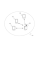
図1は、本実施形態に係る通信装置102が参加するネットワークの構成を示す。通信装置102は、ネットワーク101を構築する役割を有するアクセスポイント(AP、Access Point)である。なお、ネットワーク101は無線ネットワークである。また、通信装置103、104、105は、夫々ネットワーク101に参加する役割を有するステーション(STA、Station)である。各通信装置は、IEEE802.11be(EHT)規格に対応しており、ネットワーク101を介してIEEE802.11be規格に準拠した無線通信を実行することができる。IEEEはInstitute of Electrical and Electronics Engineersの略である。また、EHTは、Extremely High Throughputの略である。なお、EHTは、Extreme High Throughputの略であると解釈してもよい。各通信装置は、2.4GHz帯、5GHz帯、および6GHz帯の周波数帯域において通信することができる。また、各通信装置は、20MHz、40MHz、80MHz、160MHz、および320MHzの帯域幅を使用して通信することができる。
Figure 1 shows the configuration of a network in which a
通信装置102~105は、IEEE802.11be規格に準拠したOFDMA通信を実行することで、複数のユーザの信号を多重する、マルチユーザ(MU、Multi User)通信を実現することができる。OFDMA通信とは、Orthogonal Frequency Division Multiple Access(直交周波数分割多元接続)の略である。OFDMA通信では、分割された周波数帯域の一部(RU、Resource Unit)が各STAに夫々重ならないように割り当てられ、各STAに割り当てられた搬送波が直交する。そのため、APは複数のSTAと並行して通信することができる。
The
また、通信装置102~105はMU MIMO(Multi User Multiple-Input and Multiple-Output)通信によるMU通信を実現することができる。この場合、通信装置102は複数のアンテナを有し、該複数のアンテナを用いることで、複数のSTAとの同時通信を実現することができる。通信装置102は、通信装置103~105の夫々に対して送信する電波が干渉しないように調整することで、複数のSTAに対して同時に電波を送信することができる。
Furthermore,
通信装置102は、OFDMA通信とMU MIMO通信を組み合わせてMU通信を実現してもよい。即ち、APは複数のSTAとMU通信を実行する際に、サブキャリア数がある閾値以上のRUにおいて、MU MIMO通信を実行してもよい。例えば、複数のSTAにRUを割り当てる場合に、サブキャリア数が106より小さいRUにおいては一台のSTAと通信し、サブキャリア数が106以上のRUにおいて、複数のSTAによるMU MIMO通信を実行するようにしてもよい。
The
このように、MU通信を実行する場合、通信装置103~105は、各STAに対するRUの割り当てに関する情報を取得する必要がある。そのため、通信装置102は、通信装置103~105に、データ通信で用いるRUの各STAに対する割り当てについて、PHYフレームを用いて通知する。
In this way, when performing MU communication,
また、本実施形態の通信装置102は、1台のSTAあたり2以上のRUを割り当てることができる。この場合に、割り当てられるRUは、周波数成分が連続した2以上のRUであってもよいし、周波数成分が不連続な2以上のRUであってもよい。
Furthermore, the
例えば通信装置102が通信装置103~105と通信する場合に、通信装置103にのみ2以上のRUを割り当てることで、通信装置103と優先的にデータを通信することができる。このように、APは、1台のSTAに複数のRUを割り当てることで、該STAとの通信について広い周波数帯域を確保し、優先的に通信することができるようになる。
For example, when
また、1台のSTAに1つのRUしか割り当てられない場合、周波数帯域の分け方によっては、一部のRUにSTAが割り当てられない場合がある。例えば、APが3台のSTAと通信する場合に、周波数帯域を4つに分けた場合、1つのRUにはSTAが割り当てられないことになる。しかし、本実施形態の通信装置102のように、1台のSTAに複数のRUを割り当てることで、1台のSTAに対して1つのRUのみを割り当てていた場合では無駄となっていたRUも活用することができるようになる。
In addition, when only one RU can be assigned to one STA, depending on how the frequency bands are divided, some RUs may not be assigned to the STA. For example, when an AP communicates with three STAs, if the frequency bands are divided into four, one RU will not be assigned to the STA. However, by assigning multiple RUs to one STA, as in the
また、例えば通信装置102は、通信装置103に割り当てられているRUに含まれる一部の周波数成分の通信品質が通信装置102と103の少なくとも一方の移動や時間経過によって悪くなった場合に、通信品質が良い不連続な複数のRUを割り当ててもよい。具体的には、通信装置102が通信装置103に対して、サブキャリア数が52のRUを割り当てていた場合に、隣接しないサブキャリア数が26のRUを2つ割り当てるようにしてもよい。このように、APは1台のSTAに対して隣接しない2以上のRUを割り当てることで、隣接するRUの通信品質が良くない場合であっても、広い周波数帯域を確保してSTAと通信を行うことができる。
For example,
なお、通信装置102~105は、IEEE802.11be規格に対応するとしたが、これに加えて、IEEE802.11be規格より前の規格であるレガシー規格の少なくとも何れか一つに対応していてもよい。レガシー規格とは、IEEE802.11a/b/g/n/ac/ax規格のことである。また、IEEE802.11シリーズ規格に加えて、Bluetooth(登録商標)、NFC、UWB、ZigBee、MBOAなどの他の通信規格に対応していてもよい。なお、UWBはUltra Wide Bandの略であり、MBOAはMulti Band OFDM Allianceの略である。なお、OFDMはOrthogonal Frequency Division Multiplexingの略である。また、NFCはNear Field Communicationの略である。UWBには、ワイヤレスUSB、ワイヤレス1394、WiNETなどが含まれる。また、有線LANなどの有線通信の通信規格に対応していてもよい。
Although the
通信装置102の具体例としては、無線LANルーターやPCなどが挙げられるが、これらに限定されない。通信装置102は、他の通信装置とMU通信を実行することができる通信装置であれば何でもよい。また、通信装置102は、IEEE802.11be規格に準拠した無線通信を実行することができる無線チップなどの情報処理装置であってもよい。また、通信装置103~105の具体的な例としては、カメラ、タブレット、スマートフォン、PC、携帯電話、ビデオカメラなどが挙げられるが、これらに限定されない。通信装置103~105は、他の通信装置とMU通信を実行することができる通信装置であればよい。また、通信装置103~105は、IEEE802.11be規格に準拠した無線通信を実行することができる無線チップなどの情報処理装置であってもよい。また、図1のネットワークは1台のAPと3台のSTAによって構成されるネットワークであるが、APおよびSTAの台数はこれに限定されない。なお、無線チップなどの情報処理装置は、生成した信号を送信するためのアンテナを有する。
Specific examples of the
図2に、本実施形態における通信装置102のハードウェア構成を示す。通信装置102は、記憶部201、制御部202、機能部203、入力部204、出力部205、通信部206およびアンテナ207を備える。
Figure 2 shows the hardware configuration of the
記憶部201は1以上のROMやRAM等のメモリにより構成され、後述する各種動作を行うためのコンピュータプログラムや、無線通信のための通信パラメータ等の各種情報を記憶する。ROMはRead Only Memoryの、RAMはRandom Access Memoryの夫々略である。なお、記憶部201として、ROM、RAM等のメモリの他に、フレキシブルディスク、ハードディスク、光ディスク、光磁気ディスク、CD-ROM、CD-R、磁気テープ、不揮発性のメモリカード、DVDなどの記憶媒体を用いてもよい。また、記憶部201が複数のメモリ等を備えていてもよい。
The
制御部202は、例えばCPUやMPU等の1以上のプロセッサにより構成され、記憶部201に記憶されたコンピュータプログラムを実行することにより、通信装置102全体を制御する。なお、制御部202は、記憶部201に記憶されたコンピュータプログラムとOS(Operating System)との協働により、通信装置102全体を制御するようにしてもよい。また、制御部202は、他の通信装置との通信において送信するデータや信号を生成する。なお、CPUはCentral Processing Unitの、MPUは、Micro Processing Unitの略である。また、制御部202がマルチコア等の複数のプロセッサを備え、複数のプロセッサにより通信装置102全体を制御するようにしてもよい。
The
また、制御部202は、機能部203を制御して、無線通信や、撮像、印刷、投影等の所定の処理を実行する。機能部203は、通信装置102が所定の処理を実行するためのハードウェアである。
The
入力部204は、ユーザからの各種操作の受付を行う。出力部205は、モニタ画面やスピーカーを介して、ユーザに対して各種出力を行う。ここで、出力部205による出力とは、モニタ画面上への表示や、スピーカーによる音声出力、振動出力などであってもよい。なお、タッチパネルのように入力部204と出力部205の両方を1つのモジュールで実現するようにしてもよい。また、入力部204および出力部205は、夫々通信装置102と一体であってもよいし、別体であってもよい。
The
通信部206は、IEEE802.11be規格に準拠した無線通信の制御を行う。また、通信部206は、IEEE802.11be規格に加えて、他のIEEE802.11シリーズ規格に準拠した無線通信の制御や、有線LAN等の有線通信の制御を行ってもよい。通信部206は、アンテナ207を制御して、制御部202によって生成された無線通信のための信号の送受信を行う。なお、通信装置102が、IEEE802.11be規格に加えて、NFC規格やBluetooth規格等に対応している場合、これらの通信規格に準拠した無線通信の制御を行ってもよい。また、通信装置102が複数の通信規格に準拠した無線通信を実行できる場合、夫々の通信規格に対応した通信部206とアンテナ207を個別に有する構成であってもよい。通信装置102は通信部206を介して、画像データや文書データ、映像データ等のデータを通信装置103~105と通信する。なお、アンテナ207は、通信部206と別体として構成されていてもよいし、通信部206と合わせて一つのモジュールとして構成されていてもよい。
The
なお、通信装置103~105は、通信装置102と同様のハードウェア構成を有する。
Note that
図3には、本実施形態における通信装置102の機能ブロック構成を示す。通信装置102は、リソースユニット割り当て部301、Trigger Frame生成部302、およびEHT MU PPDU生成部303を備える。
Figure 3 shows a functional block configuration of the
リソースユニット割り当て部301は、通信装置102が複数のSTAとOFDMA通信を行う場合に、各STAへのRUの割り当てを行うブロックである。リソースユニット割り当て部301は、各RUの通信品質や、各STAと通信するデータのバッファ量などに基づいて、各STAへ割り当てるRUを決定する。
The resource
Trigger Frame生成部302は、STAからAPへデータを送信するUL(アップリンク、Up Link)通信を行う場合に、通信装置102が送信するTrigger Frameを生成するブロックである。Trigger Frameについては、後述の図5で説明する。
The Trigger
EHT MU PPDU生成部303は、APからSTAへデータを送信するDL(ダウンリンク、Down link)通信を行う場合に、通信装置102が送信するEHT MU PPDUを生成するブロックである。なお、PPDUとはPhysical Layer(PHY) Protocol Data Unitの略である。EHT MU PPDUについては、後述の図4で説明する。
The EHT MU
Trigger Frameも、EHT MU PPDUも、いずれもMU通信を行うSTAに対するRUの割り当てに関する情報が含まれるフレームである。 Both the Trigger Frame and the EHT MU PPDU are frames that contain information regarding the allocation of RUs to STAs performing MU communication.
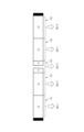
図4に、通信装置102が送信するEHT MU PPDUのフレームフォーマットの一例を示す。EHT MU PPDUとは、IEEE802.11be規格に準拠した通信装置が、DLのMU通信を実行する際に用いるフレームフォーマットである。本フレームは、先頭部からL-STF401、L-LTF402、L-SIG403、RL-SIG404、EHT-SIG-A405、EHT-SIG-B406、EHT-STF407、およびEHT-LTF408によって構成される。また、EHT-LTF408の後に、PSDU(PHY service data unit)409が続くように構成される。PSDU409には、各STA宛のデータが格納されている。なお、EHT MU PPDUの各フィールドの並び順は、これに限らない。STFはShort Training Field、LTFはLong Training Field、およびSIGはSignalの略である。また、L-はLegacyの略であり、例えばL-STFはLegacy Short Training Fieldの略である。同様にEHT-はExtremely High Throughputの略であり、例えばEHT-STFはExtremely High Throughput Short Training Fieldの略である。また、RL-SIGは、Repeated Legacy Signalの略である。
Figure 4 shows an example of the frame format of the EHT MU PPDU transmitted by the
L-STF401、L-LTF402、およびL-SIG403は、夫々IEEE802.11be規格より前に策定されたレガシー規格である、IEEE802.11a/b/g/n/ac/ax規格に対して後方互換性がある。即ち、L-STF401、L-LTF402、およびL-SIG403は、IEEE802.11ax以前のIEEE802.11シリーズ規格に対応する通信装置が復号することが可能なレガシーフィールドである。 L-STF401, L-LTF402, and L-SIG403 are backward compatible with the IEEE802.11a/b/g/n/ac/ax standards, which are legacy standards established before the IEEE802.11be standard. In other words, L-STF401, L-LTF402, and L-SIG403 are legacy fields that can be decoded by communication devices that support IEEE802.11 series standards prior to IEEE802.11ax.
L-STF401は、無線パケット信号の検出、自動利得制御(AGC、Automatic Gain Control)やタイミング検出などに用いられる。L-LTF402は高精度周波数・時刻同期化や伝搬チャンネル情報(CSI、Channnel State Information)取得などに用いられる。L-SIG403は、communication rateやlengthの情報を含んだ制御情報を送信するために用いられる。なお、RL-SIG404は省略してもよい。 L-STF401 is used for detecting wireless packet signals, automatic gain control (AGC), timing detection, etc. L-LTF402 is used for high-precision frequency and time synchronization, and for acquiring propagation channel information (CSI, Channel State Information), etc. L-SIG403 is used to transmit control information including communication rate and length information. Note that RL-SIG404 may be omitted.
EHT-SIG-A405、EHT-SIG-B406、EHT-STF407、およびEHT-LTF408は、IEEE802.11be規格に対応した通信装置が復号することが可能なEHTフィールドである。 EHT-SIG-A405, EHT-SIG-B406, EHT-STF407, and EHT-LTF408 are EHT fields that can be decoded by a communication device that complies with the IEEE802.11be standard.
EHT-SIG-B406は、commonフィールド410とuserフィールド411~419、およびpadding440から構成される。なお、userフィールドは、通信装置102がRUを割り当てるSTAの数分だけ含まれる。また、padding440はEHT-SIG-Bのサイズを調整するためのフィールドであって、省略されてもよい。なお、Commonフィールドの名称は、Common infoフィールドであってもよい。また、Userフィールドの名称は、User infoフィールドであってもよい。
EHT-SIG-
commonフィールド410には、通信装置102がEHT MU PPDUを送信する全STAに共通の情報が含まれる。commonフィールド410に含まれるサブフィールドを表1に示した。
The

RU Allocationサブフィールド420は、N×8ビットから成るフィールドであり、RUの割り当てに関する情報を示すフィールドである。具体的には、RU Allocationサブフィールド420には、PSDU409においてどのようなRUのマッピングを行っているかを示す情報が格納されている。なお、帯域幅として20MHzの帯域幅を使用する際のRUの割り当てを示す場合、RU Allocationサブフィールドは8ビット(N=1)で構成され、20MHzの帯域幅におけるRUの割り当てを示す。本実施形態では、帯域幅として最大320MHzまで使用することができるため、RU Allocationサブフィールドでは、最大で320MHzの帯域幅を使用する際のRUの割り当てを示すことになる。なお、Nは使用する帯域幅によって定まる値であり、データ通信に用いる帯域幅に応じて、N=1、2、4、8の何れかの値が入ることになる。Nと各帯域幅(20MHz、40MHz、80MHz、160MHz、および320MHz)との対応は、表1に示した通りである。なお、80+80MHzの場合とは、80MHzの帯域幅を2つ使用する場合のことである。また、160+160MHzの場合とは、160MHzの帯域幅を2つ使用する場合のことである。
The
RU Allocationサブフィールド420によって示されるRUの割り当て方の一例を図6に示した。図6の601~604には、夫々RUの分け方を示した。
An example of how RUs are allocated, as indicated by the
図6の601には、STAごとにサブキャリア数26のRUを割り当てる場合を示した。この場合、使用する周波数帯域幅20MHzあたり9台のSTAと同時にOFDMA通信を行うことができる。なお、Null Subcarriersとは、RUが設定されていないサブキャリアのことである。つまり、左から2番目のRUと3番目のRUとは、周波数成分が連続していない。また、図6では示されていないが、左から4番円のRUと5番目のRUとの間にNull Subcarrierが存在してもよい。同様に、左から5番目のRUと6番目のRUとの間にNull Subcarrierが存在してもよい。 601 in FIG. 6 shows a case where an RU with 26 subcarriers is assigned to each STA. In this case, OFDMA communication can be performed simultaneously with nine STAs per 20 MHz frequency bandwidth used. Null Subcarriers are subcarriers to which no RU is set. In other words, the second RU from the left and the third RU do not have consecutive frequency components. Although not shown in FIG. 6, a Null Subcarrier may exist between the RU in the fourth circle from the left and the fifth RU. Similarly, a Null Subcarrier may exist between the fifth RU and the sixth RU from the left.
602には、一部のSTAにサブキャリア数52のRUを割り当てる場合を示した。使用する周波数帯域幅20MHzあたり5台のSTAと同時にOFDMA通信を行うことができる。602では、4台のSTAにはサブキャリア数52のRUを割り当て、1台のSTAにはサブキャリア数26のRUを割り当てることになる。なお、サブキャリア数が26のRUとは、602の中央に位置する、サブキャリア数13のRUを組み合わせて1つのRUとして扱ったものである。なお、中央のRUは、DC(Direct Current)トーンを含むため、RU内において周波数成分が連続していないが1つのRUとして扱う。 602 shows a case where an RU with 52 subcarriers is assigned to some STAs. OFDMA communication can be performed simultaneously with five STAs per 20 MHz frequency bandwidth used. In 602, RUs with 52 subcarriers are assigned to four STAs, and an RU with 26 subcarriers is assigned to one STA. The RU with 26 subcarriers is the RU with 13 subcarriers located in the center of 602, combined and treated as one RU. Note that the central RU contains a DC (Direct Current) tone, so although the frequency components within the RU are not continuous, it is treated as one RU.
なお、602では、4つのサブキャリア数52のRUを含む割り当て方を示したが、これに限らず、サブキャリア数52のRUを1~3つ含むようにRUを割り当ててもよい。この場合、残りのRUはサブキャリア数26のものとなる。なお、602において、左から1番目のRUと2番目のRUとは、周波数成分が連続していない。同様に、4番目のRUと5番目のRUとは、周波数成分が連続していない。また、この場合も、左から2番目のRUと3番目のRUとの間、および3番目のRUと4番目のRUとの間の少なくとも一方に、Null Subcarrierが存在してもよい。 Note that in 602, an allocation method including four RUs with 52 subcarriers is shown, but this is not limiting, and RUs may be allocated to include one to three RUs with 52 subcarriers. In this case, the remaining RUs have 26 subcarriers. Note that in 602, the first and second RUs from the left do not have consecutive frequency components. Similarly, the fourth and fifth RUs do not have consecutive frequency components. Also, in this case, a Null Subcarrier may exist at least one between the second and third RUs from the left, and between the third and fourth RUs.
例えばAPが4台のSTAと通信する場合に、602で示したような分け方で周波数帯域を分けたとする。このような場合に、1台のSTAに1つのRUしか割り当てない場合、例えば中央のRU(サブキャリア数26)はSTAに割り当てられないことになる。そのため、STAへの割り当てがないRUの分、周波数帯域を効率的に利用できないことになる。しかし、本実施形態では、通信装置102は1台のSTAに複数のRUを割り当てることができるため、1台のSTAに1つのRUを割り当てる場合ではSTAの割り当てがなかったRUもSTAに割り当てることができ、帯域の利用効率を向上させることができる。
For example, when an AP communicates with four STAs, the frequency band is divided as shown in 602. In such a case, if only one RU is assigned to one STA, for example, the central RU (number of subcarriers 26) will not be assigned to the STA. As a result, the frequency band cannot be used efficiently for the RU that is not assigned to a STA. However, in this embodiment, since the
603には、一部のSTAにサブキャリア数106のRUを割り当てる場合を示した。使用する周波数帯域幅20MHzあたり3台のSTAと同時にOFDMA通信を行うことができる。603では、2台のSTAにはサブキャリア数106のRUを割り当て、1台のSTAにはサブキャリア数26のRUを割り当てることになる。あるいはサブキャリア数106のRUを複数のSTAに割り当て、該複数のSTAとMU-MIMO通信を行ってもよい。なお、604では、サブキャリア数106のRUを2つ含む割り当て方を示したが、これに限らず、サブキャリア数106のRUを1つ含むようにRUを割り当ててもよい。この場合の残りのRUは、サブキャリア数52のRUまたはサブキャリア数26のRUの少なくとも一方を、合計サブキャリア数が132となるように含むように割り当てる。また、中心のサブキャリア数26のRUにSTAを割り当てないようにしてもよい。また、この場合も、左から1番目のRUと2番目のRUとの間、および2番目のRUと3番目のRUとの間の少なくとも一方に、Null Subcarrierが存在してもよい。 603 shows a case where an RU with 106 subcarriers is assigned to some STAs. OFDMA communication can be performed simultaneously with three STAs per 20 MHz frequency bandwidth. In 603, RUs with 106 subcarriers are assigned to two STAs, and RUs with 26 subcarriers are assigned to one STA. Alternatively, RUs with 106 subcarriers may be assigned to multiple STAs, and MU-MIMO communication may be performed with the multiple STAs. Note that in 604, an allocation method including two RUs with 106 subcarriers is shown, but this is not limited to this, and RUs may be allocated to include one RU with 106 subcarriers. In this case, the remaining RUs are allocated to include at least one of an RU with 52 subcarriers or an RU with 26 subcarriers so that the total number of subcarriers is 132. In addition, it is also possible not to assign an STA to the central RU with 26 subcarriers. Also in this case, a Null Subcarrier may exist at least one between the first and second RUs from the left, and between the second and third RUs.
604には、サブキャリア数242のRUを1台のSTAに割り当てる場合を示した。使用する周波数帯域幅20MHzあたり1台のSTAとOFDMA通信を行うことができる。あるいは、サブキャリア数242のRUを複数のSTAに割り当て、該複数のSTAとMU-MIMO通信を行ってもよい。 604 shows a case where an RU with 242 subcarriers is assigned to one STA. OFDMA communication can be performed with one STA per 20 MHz of frequency bandwidth used. Alternatively, an RU with 242 subcarriers can be assigned to multiple STAs, and MU-MIMO communication can be performed with the multiple STAs.
RU Allocationサブフィールド420は8ビットごとに、図6の601~604で示したようなRUの割り当て方を示す。例えば帯域幅として80MHzを使用する場合、前半の8ビットでは601のようなRUの割り当てを示し、後半の8ビットでは603のようなRUの割り当てを示すこともできる。また、サブキャリア数106以上のRUにおいてMIMO通信を行う場合、当該RUにおいて何台のSTAとMIMO通信を行うかもRU allocationサブフィールド420において示される。
The
Tail421はCommonフィールド410のサイズを調整するために利用されるフィールドである。
Userフィールド411~419は、MU通信を行うSTAに関する情報を含むフィールドである。Userフィールドは、RU allocationサブフィールド420で示されたRUの数だけEHT MU PPDUに含まれる。例えば、通信装置102が使用する周波数帯域が20MHzで、RU allocationサブフィールド420が図6の601のようなRUの割り当てを示す場合、EHT MU PPDUには、9つのUserフィールドが含まれる。なお、RU allocationサブフィールド420において、サブキャリア数106以上のRUにおいてMIMO通信が行われると示された場合は、この限りではない。
The User fields 411 to 419 are fields that contain information about the STAs performing MU communication. The EHT MU PPDU contains as many User fields as the number of RUs indicated in the
Userフィールドには、STA-ID(Station-Identification)サブフィールド430と、MCS(Modulation and Coding Scheme、変調符号化方式)サブフィールド431とが含まれる。STA-IDサブフィールド430にはSTAの識別情報が含まれる。STA-IDに含まれる識別情報とは、具体的には、STAがAP(通信装置102)にアソシエーションした際にAPによってSTAに割り当てられる識別子であるAID(association identifier)の一部である。RU allocationサブフィールド420で示された各RUが、Userフィールド411~419のいずれのSTAに対応するかは、Userフィールドの順番によって決定される。具体的には、図6で示したRUの割り当てにおいて、一番左のRUから順に、先頭のUserフィールドのSTA-ID430において示されるSTAに割り当てられる。つまり、二番目のUserフィールドに示されるSTAには、左から2番目のRUが割り当てられる。
The User field includes a STA-ID (Station-Identification)
なお、RU allocationサブフィールド420において、MIMO通信を行うと示されたRUについては、RU allocationサブフィールド420において示された台数分のSTAが割り当てられる。RU Allocationサブフィールドに含まれる情報は、RUの分け方に加えて、MIMO通信に用いられるRUに割り当てられることになるSTAの台数も示すため、何れのRUにおいて何台のSTAによるMIMO通信が行われるかが示されることになる。例えば、RU Allocationサブフィールドにおいて、603のようなRUの分け方と、一番左のRUにおいてMIMO通信を行うSTAの台数が3台であると示された場合について考える。この場合、RU Allocationサブフィールドの後に続くUserフィールドの内、先頭から3番目までのUserフィールドに示された3台のSTAが、当該RUにおいてMIMO通信を行うSTAである。また、4番目のUserフィールドに示されたSTAは、中央のサブキャリア数26のRUにおいて通信を行う。同様に、RU Allocationサブフィールドにおいて、3番目のRUにおいてMIMO通信を行うSTAの台数が2台であると示されていた場合、5番目と6番目のUserフィールドに示されたSTAが、該RUにおいてMIMO通信を行うことになる。なお、本実施形態において、通信装置102は、STAにRUを割り当てる場合に、MIMO通信を行う複数のRUを同一のSTAに割り当ててもよい。あるいは、通信装置102は、MIMO通信を行うRUと、行わないRUとを組み合わせて同一のSTAに割り当ててもよい。
For RUs that are indicated in the
また、MCSサブフィールド431には、STA-IDサブフィールド430によって示されたSTAに対するPSDU409に使用された変調方式と符号化率とを示す情報が格納されている。MCSサブフィールド431には、具体的には、IEEE802.11be規格で規定されている、変調方式と符号化率との組み合わせに対応する数値が含まれている。
The
図7には、1台のSTAに複数のRUを割り当てる場合の、RUの割り当て方の一例を示した。図7では、周波数帯域幅20MHzごとに、サブキャリア数52のRU4つと、サブキャリア数26のRU1つに分割し、各STAに不連続なRUを複数割り当てる場合について示した。この場合に、左から1番目のRU701と4番目のRU704とを、AIDが1であるSTA(例えば通信装置103)に割り当てる。また、左から2番目のRU702と5番目のRU705とを、AIDが2であるSTA(例えば通信装置104)に割り当てる。また、左から3番目のRU(サブキャリア数26のRU)703を、AIDが3のSTA(例えば通信装置105)に割り当てる。このような場合に、APである通信装置102は、EHT-SIG-B406に、同一のSTA-IDを有するUserフィールドを複数含むEHT MU PPDUを送信する。具体的には、1番目と4番目のUserフィールドにAID=1のSTAのSTA―IDを含み、2番目と5番目のUserフィールドにAID=2のSTAのSTA-IDを含むEHT-SIG-B406を有するEHT MU PPDUを送信する。このように、通信装置102は、同一のSTA-IDを含む2以上のUserフィールドを、夫々の割り当てられたRUに対応する順で複数EHT MU PPDUに含めることで、1台のSTAに周波数成分が連続しない複数のRUを割り当てることができる。
Figure 7 shows an example of how to assign RUs when multiple RUs are assigned to one STA. Figure 7 shows a case where each frequency bandwidth of 20 MHz is divided into four RUs with 52 subcarriers and one RU with 26 subcarriers, and multiple non-contiguous RUs are assigned to each STA. In this case, the
なお、図7では、1台のSTAに周波数成分が不連続な複数のRUを割り当てる場合を例としたが、これに限らず、通信装置102は、1台のSTAに周波数成分が連続する複数のRUを割り当ててもよい。例えば、通信装置102は、RU702とRU703とをAID=2のSTAに割り当ててもよい。この場合に、EHT MU PPDUは、2番目と3番目のUserフィールドとにAID=2のSTAのSTA-IDを含むEHT-SIG-B406を含む。
Note that FIG. 7 shows an example in which multiple RUs with discontinuous frequency components are assigned to one STA, but this is not limiting, and
あるいは、通信装置107は、RU703について、サブキャリア数13の2つのRUに分けて、夫々をSTAに割り当ててもよい。例えば、AID=2のSTAにRU702とRU703の前半部分(サブキャリア数13のRU)とを割り当てることで、合計サブキャリア数65のRUを割り当てるようにしてもよい。また、AID=1のSTAに、RU703の後半部分と、RU704とを割り当てることで、合計サブキャリア数65のRUを割り当てるようにしてもよい。この場合に、EHT MU PPDUは、2番目と3番目のUserフィールドとにAID=2のSTAのSTA-IDを含み、4番目と5番目のUserフィールドとにAID=1のSTAのSTA-IDを含むEHT-SIG-B406を含む。 Alternatively, the communication device 107 may divide RU703 into two RUs with 13 subcarriers, and assign each to a STA. For example, the communication device 107 may assign RU702 and the first half of RU703 (an RU with 13 subcarriers) to the STA with AID=2, thereby assigning an RU with a total of 65 subcarriers. The communication device 107 may also assign RUs with a total of 65 subcarriers to the STA with AID=1, by assigning the second half of RU703 and RU704. In this case, the EHT MU PPDU includes an EHT-SIG-B406 that includes the STA-ID of the STA with AID=2 in the second and third User fields, and the STA-ID of the STA with AID=1 in the fourth and fifth User fields.
図7に示したように、複数のRUを1台のSTAに割り当てることで、従来の方法ではSTAが割り当てられなかったRUにもSTAを割り当てることができるようになるため、周波数帯域の利用効率が向上する。 As shown in Figure 7, by assigning multiple RUs to one STA, it becomes possible to assign STAs to RUs that could not be assigned STAs using conventional methods, thereby improving the efficiency of frequency band usage.
なお、本実施形態では、EHT MU PPDUではRUの分け方を示すRU Allocationサブフィールド420が、Commonフィールド410に含まれるとしたが、これに限らない。EHT MU PPDUにおいて、Userフィールド411~419内に、各STAに割り当てられたRUを示す情報を含めるようにしてもよい。この場合、1つのSTAに複数のRUを割り当てる場合は、同一のSTAを示す複数のUserフィールドを含む代わりに、複数のRUを示す情報を含む1つのUserフィールドを含めるようにしてもよい。
In the present embodiment, the
図5には、通信装置102が送信するTrigger Frameのフレームフォーマットの一例を示す。Trigger Frameとは、IEEE802.11be規格に準拠した通信装置が、ULのMU通信を実行する際に用いるフレームフォーマットである。通信装置102は、Trigger FrameにおいてUL通信を行うSTAと、夫々のSTAに割り当てたRUを示すことで、各STAから指定したRUを介して並行してデータを受信する。
Figure 5 shows an example of the frame format of a Trigger Frame transmitted by the
Trigger Frameは先頭部から、Frame control505、Duration506、RA507、TA508の各フィールドによって構成される。さらにTA508に続いて、Common Info501、User Info502、Padding503、およびFCS504の各フィールドによって構成される。
The Trigger Frame is composed of the
Frame control505には、フレームがマネジメントフレームであるか、あるいはコントロールフレームであるか、あるいはデータフレームであるかを示す情報と、フレームのサブタイプを示す情報とが含まれる。フレームのサブタイプとは、そのフレームがビーコンであるか、アクションであるかなどを示す情報である。Trigger Frameの場合、フレームがコントロールフレームであることを示す情報と、サブタイプがTriggerであることを示す情報が入る。
Duration506は、Trigger Frameを受信したSTAに、通信を開始させない期間であるNAV(network allocation vector)を設定させるための情報を含む。
RA(receiver address)507には、トリガーフレームの種類や、User Infoフィールドの有無に基づいて決定される値が含まれる。 RA (receiver address) 507 contains a value that is determined based on the type of trigger frame and the presence or absence of a User Info field.
TA(transmitter address)508には、トリガーフレームを送信する通信装置のアドレスが含まれる。あるいはトリガーフレームが複数のネットワークに向けて送信される場合、TA508には、トリガーフレームを送信した通信装置が属するネットワークの識別子(BSSID、Basic Service Set Identifier)が含まれる。
The TA (transmitter address) 508 includes the address of the communication device that transmits the trigger frame. Alternatively, if the trigger frame is transmitted to multiple networks, the
Common Info501には全STA共通の情報が含まれる。具体的には、先頭からTrigger Type510、Length511、およびReserved512のサブフィールドを含む。Trigger Type510は0を示し、Length511には全STA共通の通信時間が設定される。
Trigger Type510が0の場合、Trigger FrameにはUser Infoフィールド(502-1~502-N)が追加される。User Info502には、STAを識別するためのAID520が含まれる。RU Allocation521には、AID520で示されたSTAに割り当てられたRUのサイズや、該STAに割り当てられたRUが、周波数の低いRUから数えて何番目のRUかを示す情報が含まれる。また、Trigger Frameには、STAがAP宛に送信するデータの変調方式や符号化率を指定するための情報が含まれるUL MCS522が含まれる。Reserved523は将来のために予約されている領域である。
When
User Info502のAID520に示されたSTAあたり1つのRUを割り当てる場合、一回のTrigger Frameでは1台のSTAあたり1つのUser Infoフィールドが含まれる。本実施形態において、1台のSTAに複数のRUを割り当てる場合、1回のTrigger Frameに、同一のAIDを含むUser Infoが複数含まれる。図7で示したように、AID=1のSTAに左から1番目と4番目のRUとを割り当てる場合を例とする。この場合、Trigger FrameにはAID=1かつ1番目のRUを示すRU Allocationを含むUser Infoと、AID=1かつ4番目のRUを示すRU Allocationを含むUser Infoとが含まれる。
When one RU is allocated to the STA indicated in
なお、本実施形態では、複数のRUを同一STAに割り当てる場合、同一のAIDを有するUser InfoをTrigger Frameに複数含めるとしたが、これに限らない。通信装置102は、1つのUser InfoのRU Allocationにおいて複数のRUを示すTrigger Frameを生成してもよい。この場合に、1つのUser Infoに含まれる1つのRU Allocationフィールドに複数のRUについての情報が含まれてもよい。あるいは、1つのUser Infoに複数のRU Allocationフィールドが含まれてもよい。
In this embodiment, when multiple RUs are allocated to the same STA, multiple User Infos having the same AID are included in the Trigger Frame, but this is not limited to the above. The
padding503はTrigger Frameのサイズを調整するためのフィールドであって、省略されてもよい。 Padding 503 is a field for adjusting the size of the Trigger Frame and may be omitted.
FCS504は、Frame check sequenceの略であり、通信途中でデータに誤りが生じていないか調べるために用いられる誤り検出符号のことである。 FCS504 stands for Frame check sequence, and is an error detection code used to check whether any errors have occurred in the data during communication.
図8は、通信装置102がDL-OFDMA通信を行う場合に、記憶部201に記憶されたコンピュータプログラムを制御部202が読み出し、実行することで実行される処理を示すフローチャートである。
Figure 8 is a flowchart showing the processing performed by the
通信装置102は、STA宛にDL-OFDMA通信を行うようにユーザに指示された場合に本フローの処理を開始する。あるいは所定のSTAに宛てたデータのバッファ量が所定の閾値を超えた場合に、本フローの処理を開始してもよいし、所定の台数のSTAに宛てたデータのバッファ量が所定の閾値を超えた場合に開始してもよい。あるいは通信装置102で動作しているアプリケーションからの指示に基づいて本フローの処理を開始してもよい。
The
まず通信装置102は、自装置に格納されている各STAを宛先とするデータのバッファ量を取得する(S800)。本ステップでは、後述のS804でEHT MU PPDUを送信する相手装置となるSTA宛のデータのバッファ量のみを取得すればよい。
First, the
次に、通信装置102は、各STAとの通信品質を取得する(S801)。この場合、通信装置102は、各STAと前回通信を行った際に使用したRUにおける通信品質を取得してもよいし、一時的に割り振ったRUにおける通信品質を取得してもよい。ここで取得する通信品質とは、RSSIまたはSNRの少なくとも一方である。なお、RSSIとはReceived Signal Strength Indication(受信信号強度)の略である。また、SNRとはSignal-to-Noise Ratio(信号対ノイズ比)の略である。通信装置102は各STAと前回通信を行った際のRSSIまたはSNRの少なくとも一方を記憶していてもよい。あるいは、通信装置102(AP)がSTAに指示し、STAから通信装置102に宛ててフレームを送信させることで、通信品質を測定してもよい。具体的には、まず通信装置102からSTAにNDP(null data PPDU) Announcementフレームを送信することで、STAにAPへのNDPフレームの送信を指示する。STAは、NDP Announcementフレームを受信すると、APへNDPフレームを送信する。APは受信したNDPフレームを用いて通信品質を測定する。このように、STAにNDPフレームを送信させる方法をNDP Soundingという。あるいは、APからSTAにフレームを送信し、STAに通信品質を測定させ、その測定結果をSTAから受信することで通信品質を取得するようにしてもよい。
Next, the
なお、S801において、RUの通信品質ではなく、STAとの通信に使用する周波数チャネル全体の通信品質を取得するようにしてもよい。 In addition, in S801, the communication quality of the entire frequency channel used for communication with the STA may be obtained instead of the communication quality of the RU.
通信装置102は、S800で取得したバッファ量と、S801で取得した通信品質とに基づいて、各STAへ割り当てるRUを決定する(S802)。例えば、通信装置102は、S800で取得したバッファ量が所定の閾値を超えるSTAに対して、複数のRUを割り当てるように決定する。また、S801で取得した通信品質であるRSSIおよびSNRの少なくとも一方が所定の閾値以下の場合、複数のRUを割り当てるように決定する。また、あるSTAについてS801で取得したRSSIおよびSNRの少なくとも一方が所定の閾値以下の場合は、S801で利用したRUと異なるRUを該STAに割り当てるようにしてもよい。例えばあるSTAにサブキャリア数52のRUを割り当てたいが、あるRU(サブキャリア数26)と周波数成分が連続する別のRU(サブキャリア数26)の通信品質が所定の条件を満たさない場合があるとする。このような場合、通信装置102は該STAに対して周波数成分が不連続なサブキャリア数26のRUを2つ割り当てるようにする。なお、S802において、通信装置102はバッファ量と通信品質との両方に基づいてRUの割り当てを決定するとしたが、これに限らず、何れか一方のみに基づいて決定してもよい。その場合、通信装置102は、RUの割り当ての決定に使用しない情報(バッファ量または通信品質)については、取得する必要がないため、対応するS800またはS801をスキップしてもよい。
The
通信装置102は各STAに対するRUの割り当てを決定すると、それに応じたUserフィールドを含むEHT MU PPDUを生成する(S803)。S802において、複数のRUを1台のSTAに割り当てると決定した場合、S803で生成されるEHT MU PPDUには、同一のSTA-IDを含むUserフィールドが複数含まれる。
When the
なお本実施形態では、複数のRUを1台のSTAに割り当てていることをUserフィールドにおいて示したが、これに限らず、EHT MU PPDUに含まれるUserフィールドより前の他のフィールドで示すようにしてもよい。複数のRUが1台のSTAに割り当てられていないと示された場合、STAは対応するUserフィールドを検出した以降はUserフィールドの解析を行う必要がない。これにより、STAの処理負荷を低減させることができる。 In this embodiment, the User field indicates that multiple RUs are assigned to one STA, but this is not limited to the above, and may be indicated in another field prior to the User field included in the EHT MU PPDU. If it is indicated that multiple RUs are not assigned to one STA, the STA does not need to analyze the User field after detecting the corresponding User field. This reduces the processing load on the STA.
通信装置102はS803で生成したEHT MU PPDUをSTAに送信する(S804)。S802で、同一のSTAに複数のRUを割り当てると決定した場合、本ステップで送信されるEHT MU PPDUでは、複数のRUに同一のSTA宛のデータが含まれる。本ステップでは図4に示したL-STF401から順に、L-LTF402、L-SIG403、RL-SIG404、EHT-SIG-A405、EHT-SIG-B406の順で各フィールドに対応する信号が送信される。さらに、EHT-SIG-B406に続いて、EHT-STF407、EHT-LTF408、およびPSDU409の各フィールドに対応する信号が順番に送信される。なお、通信装置102はS803で上記のフィールドをすべて生成してからS804の送信を開始してもよいし、あるいはS803の生成とS804の送信とを並行して行うようにしてもよい。具体的には、通信装置102は、L-STF401を生成し、生成したL-STF401に対応する信号を送信することと並行して、次に送信されるフィールドであるL-LTF402の生成を行うようにしてもよい。なお、S804で送信されたEHT MU PPDUを受信するSTAは、L-STF401、L-LTF402、L-SIG403、RL-SIG404、EHT-SIG-A405、EHT-SIG-B406の順に各フィールドに対応する信号を受信する。また、該STAは、EHT-SIG-B406に続いて、EHT-STF407、EHT-LTF408、およびPSDU409の順で各フィールドに対応する信号を受信する。
The
以上、図8に示した処理を行うことで、通信装置102は同一のSTAに複数のRUを割り当てることを示す情報を含むEHT MU PPDUを送信することができる。これにより、通信装置102は周波数帯域の利用効率を向上させることができる。また、通信装置102は、STAへのデータのバッファ量と、各STAとの通信品質を考慮して、複数のRUを同一のSTAに割り当てたり、1つのRUを1台のSTAに割り当てたりすることができる。通信装置102は各STAに対するデータのバッファ量や、各STAとの通信品質に基づいて、フレキシブルにRUを割り当てることができる。
By performing the process shown in FIG. 8 as described above, the
図9は、通信装置102がUL-OFDMA通信を行う場合に、記憶部201に記憶されたコンピュータプログラムを制御部202が読み出し、実行することで実行される処理を示すフローチャートである。
Figure 9 is a flowchart showing the processing performed by the
通信装置102は、STA宛にUL-OFDMA通信を行うようにユーザに指示された場合に本フローの処理を開始する。あるいは、STAからUL-OFDMA通信を行うように要求を受けたことに基づいて本フローの処理を開始してもよい。あるいは通信装置102で動作しているアプリケーションからの指示に基づいて本フローの処理を開始してもよい。
The
通信装置102は、ネットワーク101に属する各STAが保持する送信データのバッファ量を取得する(S900)。なお、本ステップにおいて、ネットワーク101に属するSTAのうち、一部のSTAのバッファ量のみ取得するようにしてもよい。通信装置102は、IEEE802.11ax規格に規定されているBuffer Status Report(BSR)フレームによってSTAからバッファ量の通知を受ける。具体的には、まず通信装置102は各STAに、各STAが保持するデータ量を通知するように要求するBSR Pollを送信する。要求フレームを受信した各STAは、それに対する応答として、自装置が保持する通信装置102宛のデータのデータ量を通知するBuffer status reportフレームを通信装置102に送信する。通信装置102は、受信したBSRフレームから、各STAが保持する通信装置102宛のデータのデータ量を取得することができる。
The
通信装置102は、各STAとの通信品質を取得する(S901)。本ステップの処理は、S801と同様である。
The
次に通信装置102は、S900で取得したバッファ量と、S901で取得した通信品質に基づき、各STAへ割り当てるRUを決定する(S902)。本ステップの処理は、S802と同様である。
Next, the
次に、通信装置102は、各STAに対するRUの割り当てを決定すると、それに応じたUser infoフィールドを含むTrigger Frameを生成する(S903)。S902において、複数のRUを1台のSTAに割り当てると決定した場合、S903で生成されるTrigger Frameには、同一のAIDを含むUser Infoフィールドが複数含まれる。あるいは、複数のRUを示すRU allocationサブフィールドを含むUser Infoフィールドを有するTrigger Frameを生成してもよい。
Next, when the
なお、同一AIDを含むUser Infoフィールドを複数含む場合、同一のAIDを含むUser InfoフィールドがTrigger Frame内で連続して配置されるようにしてもよい。この場合、Trigger Frameを受信するSTAは、自装置宛のUser Infoフィールドを解析した後、自装置と異なるSTA宛のUser Infoフィールドを検出した場合に、以降のUser Infoフィールドを解析する必要がなくなる。これにより、STAの処理負荷を低減することができる。あるいは、複数のRUを1台のSTAに割り当てているか否かを、Trigger Frameに含まれる他のフィールドで示すようにしてもよい。例えば、図5に示したReserved512において、当該情報を示してもよい。Reserved512において、同一STAに複数のRUが割り当てられていないと示されていた場合、STAは自装置宛のUser Infoフィールド以降のUser Infoフィールドを解析する必要がなくなる。
In addition, when a Trigger Frame contains multiple User Info fields containing the same AID, the User Info fields containing the same AID may be arranged consecutively within the Trigger Frame. In this case, when a STA receiving the Trigger Frame detects a User Info field addressed to a STA other than the STA after analyzing the User Info field addressed to the STA, it is not necessary to analyze the subsequent User Info fields. This reduces the processing load of the STA. Alternatively, whether multiple RUs are assigned to one STA may be indicated by another field included in the Trigger Frame. For example, the information may be indicated in
次に通信装置102は、S904で生成したTrigger FrameをSTAに送信する(S904)。本ステップでは図5に示したFrame control505から順に、Duration506、RA507、TA508の順で各フィールドに対応する信号が送信される。さらに、TA508に続いて、Common Info501、User Info502、Padding503、およびFCS504の各フィールドに対応する信号が順番に送信される。なお、通信装置102はS903で上記のフィールドをすべて生成してからS904の送信を開始してもよいし、あるいはS903の生成とS904の送信とを並行して行うようにしてもよい。具体的には、通信装置102は、Frame control505を生成し、生成したFrame control505に対応する信号を送信することと並行して、次に送信されるフィールドであるDuration506の生成を行うようにしてもよい。なお、S904で送信されたTrigger Frameを受信するSTAは、Frame control505から順に、Duration506、RA507、TA508の順で各フィールドに対応する信号を受信する。また、該STAは、TA508に続いて、Common Info501、User Info502、Padding503、およびFCS504の順で各フィールドに対応する信号を受信する。
Next, the
そして、通信装置102は、S904で送信したTrigger Frameにおいて指定したRUを利用して、STAからデータを受信する。具体的には、通信装置102はEHT TB(Trigger Based) PPDUによって各STAからデータを受信する。
Then, the
以上、図9に示した処理を行うことで、通信装置102は同一のSTAに複数のRUを割り当てることを示す情報を含むTrigger Frameを送信することができる。これにより、通信装置102は周波数帯域の利用効率を向上させることができる。また、通信装置102は、STAにおけるAPへのデータのバッファ量と、各STAとの通信品質を考慮して、複数のRUを同一のSTAに割り当てたり、1つのRUを1台のSTAに割り当てたりすることができる。通信装置102は各STAにおけるAPへのデータのバッファ量や、各STAとの通信品質に基づいて、フレキシブルにRUを割り当てることができる。
By performing the process shown in FIG. 9 as described above, the
なお、本実施形態では、IEEE802.11be規格に準拠した無線通信を例として説明したが、これに限らず、レガシー規格であるIEEE802.11ax規格に準拠した無線通信において同様の処理を行ってもよい。この場合、EHTフィールドは、HEフィールドに置き換えられ、例えばEHT-SIG-Bフィールドの名称はHE-SIG-Bフィールドとなる。あるいはIEEE802.11be規格の後継の規格に準拠した無線通信によって実現されてもよい。この場合も、EHTフィールドは、該当の規格に準拠する対応のフィールドに置き換わる。 In this embodiment, wireless communication conforming to the IEEE802.11be standard has been described as an example, but the present invention is not limited to this, and similar processing may be performed in wireless communication conforming to the legacy standard IEEE802.11ax standard. In this case, the EHT field is replaced with the HE field, and for example, the name of the EHT-SIG-B field becomes the HE-SIG-B field. Alternatively, this may be achieved by wireless communication conforming to a successor standard to the IEEE802.11be standard. In this case, the EHT field is replaced with a corresponding field conforming to the relevant standard.
なお、図8、および図9に示した通信装置102のフローチャートの少なくとも一部または全部をハードウェアにより実現してもよい。ハードウェアにより実現する場合、例えば、所定のコンパイラを用いることで、各ステップを実現するためのコンピュータプログラムからFPGA上に専用回路を生成し、これを利用すればよい。FPGAとは、Field Programmable Gate Arrayの略である。また、FPGAと同様にしてGate Array回路を形成し、ハードウェアとして実現するようにしてもよい。また、ASIC(Application Specific Integrated Circuit)により実現するようにしてもよい。
Note that at least a part or all of the flowcharts of the
本発明は、上述の実施形態の1以上の機能を実現するプログラムを、ネットワーク又は記憶媒体を介してシステム又は装置に供給し、そのシステム又は装置のコンピュータにおける1つ以上のプロセッサがプログラムを読出し実行する処理でも実現可能である。また、1以上の機能を実現する回路(例えば、ASIC)によっても実現可能である。 The present invention can also be realized by supplying a program that realizes one or more of the functions of the above-mentioned embodiments to a system or device via a network or storage medium, and having one or more processors in the computer of the system or device read and execute the program. It can also be realized by a circuit (e.g., an ASIC) that realizes one or more of the functions.
101 ネットワーク
102 通信装置(AP)
103 通信装置(STA)
104 通信装置(STA)
105 通信装置(STA)
103 Communication device (STA)
104 Communication device (STA)
105 Communication device (STA)
Claims (12)
L-STF(Legacy-Short Training Field)と、
L-LTF(Legacy-Long Training Field)と、
L-SIG(Legacy-Signal)と、
EHT-STF(Extremely High Throughput-Short Training Field)と、
EHT-LTF(Extremely High Throughput-Long Training Field)と、を少なくとも含むEHT MU(Multi User) PPDU(Physical Layer Protocol Data Unit)を生成する生成手段と、
前記生成手段によって生成された前記EHT MU PPDUを送信する送信手段と、
を有し、
前記L-SIGと前記EHT-STFの間に位置するフィールドには、1以上のRU(Resource Unit)割り当てを示すサブフィールドと、ユーザ情報を示すUserフィールドが含まれ、前記EHT MU PPDUの帯域幅が20MHzである場合に前記RU割り当てを示すサブフィールドの数は1つであり、前記EHT MU PPDUの帯域幅が40MHzである場合に前記RU割り当てを示すサブフィールドの数は1つであり、前記EHT MU PPDUの帯域幅が80MHzである場合に前記RU割り当てを示すサブフィールドの数は2つであり、前記EHT MU PPDUの帯域幅が160MHzである場合に前記RU割り当てを示すサブフィールドの数は4つであり、前記RU割り当てを示すサブフィールドのうち少なくとも1つのRU割り当てを示すサブフィールドと、前記Userフィールドとにより1つの他の通信装置に複数のRUが割り当てられていることを示すことを特徴とする通信装置。 1. A communication device, comprising:
L-STF (Legacy-Short Training Field) and
L-LTF (Legacy-Long Training Field) and
L-SIG (Legacy-Signal) and
EHT-STF (Extremely High Throughput-Short Training Field),
A generating means for generating an EHT MU (Multi User) PPDU (Physical Layer Protocol Data Unit) including at least an EHT-LTF (Extremely High Throughput-Long Training Field);
a transmitting means for transmitting the EHT MU PPDU generated by the generating means;
having
a field located between the L-SIG and the EHT-STF includes a subfield indicating one or more RU (Resource Unit) allocations and a User field indicating user information, wherein when the bandwidth of the EHT MU PPDU is 20 MHz, the number of subfields indicating the RU allocation is one, when the bandwidth of the EHT MU PPDU is 40 MHz, the number of subfields indicating the RU allocation is one, when the bandwidth of the EHT MU PPDU is 80 MHz, the number of subfields indicating the RU allocation is two, and when the bandwidth of the EHT MU PPDU is 160 MHz, the number of subfields indicating the RU allocation is four, and the communication device indicates that a plurality of RUs are allocated to one other communication device by at least one subfield indicating RU allocation and the User field .
前記他の通信装置との通信品質を取得する第2の取得手段と、
前記第1の取得手段によって取得した前記バッファ量と、前記第2の取得手段によって取得した前記通信品質との少なくとも一方に基づいて、前記他の通信装置に対するRUの割り当てを決定する決定手段を更に有し、
前記生成手段は前記決定手段によって決定されたRUの割り当てに基づいて、前記EHT MU PPDUを生成することを特徴とする請求項1から6のいずれか1項に記載の通信装置。 a first acquisition means for acquiring a buffer amount of data destined for the other communication device;
A second acquisition means for acquiring a communication quality with the other communication device;
a determining unit that determines an allocation of RUs to the other communication device based on at least one of the buffer amount acquired by the first acquiring unit and the communication quality acquired by the second acquiring unit,
7. The communication device according to claim 1, wherein the generating means generates the EHT MU PPDU based on the RU allocation determined by the determining means.
L-STF(Legacy-Short Training Field)と、
L-LTF(Legacy-Long Training Field)と、
L-SIG(Legacy-Signal)と、
EHT-STF(Extremely High Throughput-Short Training Field)と、
EHT-LTF(Extremely High Throughput-Long Training Field)と、を含むEHT MU(Multi User) PPDU(Physical Layer Protocol Data Unit)を生成する生成工程と、
前記生成工程において生成された前記EHT MU PPDUを送信する送信工程と、
を有し、
前記L-SIGと前記EHT-STFの間に位置するフィールドには、1以上のRU(Resource Unit)割り当てを示すサブフィールドと、ユーザ情報を示すUserフィールドが含まれ、前記EHT MU PPDUの帯域幅が20MHzである場合に前記RU割り当てを示すサブフィールドの数は1つであり、前記EHT MU PPDUの帯域幅が40MHzである場合に前記RU割り当てを示すサブフィールドの数は1つであり、前記EHT MU PPDUの帯域幅が80MHzである場合に前記RU割り当てを示すサブフィールドの数は2つであり、前記EHT MU PPDUの帯域幅が160MHzである場合に前記RU割り当てを示すサブフィールドの数は4つであり、前記RU割り当てを示すサブフィールドのうち少なくとも1つのRU割り当てを示すサブフィールドと、前記Userフィールドとにより1つの他の通信装置に複数のRU(Resource Unit)が割り当てられていることを示すことを特徴とする制御方法。 A method for controlling a communication device, comprising:
L-STF (Legacy-Short Training Field) and
L-LTF (Legacy-Long Training Field) and
L-SIG (Legacy-Signal) and
EHT-STF (Extremely High Throughput-Short Training Field),
a generation step of generating an EHT MU (Multi User) PPDU (Physical Layer Protocol Data Unit) including an EHT-LTF (Extremely High Throughput-Long Training Field);
a transmitting step of transmitting the EHT MU PPDU generated in the generating step;
having
a field located between the L-SIG and the EHT-STF includes a subfield indicating one or more RU (Resource Unit) allocations and a User field indicating user information, wherein when the bandwidth of the EHT MU PPDU is 20 MHz, the number of subfields indicating the RU allocation is one, when the bandwidth of the EHT MU PPDU is 40 MHz, the number of subfields indicating the RU allocation is one, when the bandwidth of the EHT MU PPDU is 80 MHz, the number of subfields indicating the RU allocation is two, and when the bandwidth of the EHT MU PPDU is 160 MHz, the number of subfields indicating the RU allocation is four, and wherein at least one of the subfields indicating the RU allocation and the User field indicate that a plurality of RUs (Resource Units) are allocated to one other communication device.
Priority Applications (7)
| Application Number | Priority Date | Filing Date | Title |
|---|---|---|---|
| JP2019202783A JP7527772B2 (en) | 2019-11-07 | 2019-11-07 | COMMUNICATION DEVICE, CONTROL METHOD, AND PROGRAM |
| BR112022007557A BR112022007557A2 (en) | 2019-11-07 | 2020-10-27 | COMMUNICATION DEVICE, CONTROL METHOD AND PROGRAM |
| KR1020227017804A KR20220092545A (en) | 2019-11-07 | 2020-10-27 | Communication device, control method and program |
| EP20886043.7A EP4057743A4 (en) | 2019-11-07 | 2020-10-27 | Communication device, control method, and program |
| CN202080074217.0A CN114631343A (en) | 2019-11-07 | 2020-10-27 | Communication device, control method, and program |
| PCT/JP2020/040257 WO2021090732A1 (en) | 2019-11-07 | 2020-10-27 | Communication device, control method, and program |
| US17/735,468 US20220264579A1 (en) | 2019-11-07 | 2022-05-03 | Communication apparatus, control method, and storage medium |
Applications Claiming Priority (1)
| Application Number | Priority Date | Filing Date | Title |
|---|---|---|---|
| JP2019202783A JP7527772B2 (en) | 2019-11-07 | 2019-11-07 | COMMUNICATION DEVICE, CONTROL METHOD, AND PROGRAM |
Publications (3)
| Publication Number | Publication Date |
|---|---|
| JP2021077981A JP2021077981A (en) | 2021-05-20 |
| JP2021077981A5 JP2021077981A5 (en) | 2023-06-26 |
| JP7527772B2 true JP7527772B2 (en) | 2024-08-05 |
Family
ID=75848349
Family Applications (1)
| Application Number | Title | Priority Date | Filing Date |
|---|---|---|---|
| JP2019202783A Active JP7527772B2 (en) | 2019-11-07 | 2019-11-07 | COMMUNICATION DEVICE, CONTROL METHOD, AND PROGRAM |
Country Status (7)
| Country | Link |
|---|---|
| US (1) | US20220264579A1 (en) |
| EP (1) | EP4057743A4 (en) |
| JP (1) | JP7527772B2 (en) |
| KR (1) | KR20220092545A (en) |
| CN (1) | CN114631343A (en) |
| BR (1) | BR112022007557A2 (en) |
| WO (1) | WO2021090732A1 (en) |
Families Citing this family (3)
| Publication number | Priority date | Publication date | Assignee | Title |
|---|---|---|---|---|
| MX2022008607A (en) * | 2020-01-10 | 2022-10-20 | Huawei Tech Co Ltd | Resource allocation signalng in awreless local areanetwork preamble. |
| CN116488783B (en) * | 2020-01-11 | 2024-04-12 | 华为技术有限公司 | Method for indicating punching information and communication device |
| JP7494789B2 (en) | 2021-04-30 | 2024-06-04 | 株式会社デンソー | Motor with reducer |
Citations (2)
| Publication number | Priority date | Publication date | Assignee | Title |
|---|---|---|---|---|
| JP2018526840A (en) | 2015-07-01 | 2018-09-13 | パナソニックIpマネジメント株式会社 | Transmitting apparatus, transmitting method, and integrated circuit |
| US20190327019A1 (en) | 2018-04-23 | 2019-10-24 | Avago Technologies General Ip (Singapore) Pte. Ltd. | Range extension of wireless communication device |
Family Cites Families (12)
| Publication number | Priority date | Publication date | Assignee | Title |
|---|---|---|---|---|
| KR102700839B1 (en) | 2014-06-08 | 2024-08-30 | 엘지전자 주식회사 | Uplink multi-user transmission method in wireless lan system and apparatus therefor |
| US10548146B2 (en) * | 2015-04-16 | 2020-01-28 | Lg Electronics Inc. | Channel sounding method in wireless communication system and device for same |
| US10505691B2 (en) * | 2015-08-20 | 2019-12-10 | Lg Electronics Inc. | Method and apparatus for configuring frame unit comprising control field indicating data fields in wireless LAN system |
| US11044056B2 (en) * | 2018-02-01 | 2021-06-22 | Mediatek Singapore Pte. Ltd. | Enhanced resource unit allocation schemes for OFDMA transmission in WLAN |
| US11457439B2 (en) * | 2018-04-20 | 2022-09-27 | Lg Electronics Inc. | Method and device for executing communication via uplink access in wireless LAN system |
| JP2019202783A (en) | 2018-05-21 | 2019-11-28 | 京セラドキュメントソリューションズ株式会社 | Shock absorber |
| JP7308623B2 (en) * | 2019-02-28 | 2023-07-14 | キヤノン株式会社 | Information processing device, its control method, and program |
| JP7398874B2 (en) * | 2019-04-11 | 2023-12-15 | キヤノン株式会社 | Communication device and its communication method, information processing device and its control method, and program |
| US11212705B2 (en) * | 2019-05-28 | 2021-12-28 | Nxp Usa, Inc. | Extra high throughput preamble |
| US11665574B2 (en) * | 2019-10-25 | 2023-05-30 | Qualcomm Incorporated | Physical layer preamble design for special packet types |
| JP7379100B2 (en) * | 2019-11-08 | 2023-11-14 | キヤノン株式会社 | Communication devices, communication methods, and programs |
| CN113133115A (en) * | 2020-01-10 | 2021-07-16 | 华为技术有限公司 | Method and apparatus for indicating Multi-RU merging of multiple resource units |
-
2019
- 2019-11-07 JP JP2019202783A patent/JP7527772B2/en active Active
-
2020
- 2020-10-27 BR BR112022007557A patent/BR112022007557A2/en unknown
- 2020-10-27 CN CN202080074217.0A patent/CN114631343A/en active Pending
- 2020-10-27 EP EP20886043.7A patent/EP4057743A4/en active Pending
- 2020-10-27 WO PCT/JP2020/040257 patent/WO2021090732A1/en unknown
- 2020-10-27 KR KR1020227017804A patent/KR20220092545A/en unknown
-
2022
- 2022-05-03 US US17/735,468 patent/US20220264579A1/en active Pending
Patent Citations (2)
| Publication number | Priority date | Publication date | Assignee | Title |
|---|---|---|---|---|
| JP2018526840A (en) | 2015-07-01 | 2018-09-13 | パナソニックIpマネジメント株式会社 | Transmitting apparatus, transmitting method, and integrated circuit |
| US20190327019A1 (en) | 2018-04-23 | 2019-10-24 | Avago Technologies General Ip (Singapore) Pte. Ltd. | Range extension of wireless communication device |
Non-Patent Citations (2)
| Title |
|---|
| Roya Doostnejad (Intel Corporation) et al.,"Implicit Channel Sounding in IEEE 802.11",IEEE802.11-19/0768r1,[online],2019年06月24日,slides 1-14,[retrieved on 2024-01-22], Retrieved from <https://mentor.ieee.org/802.11/dcn/19/11-19-0768-01-00be-implicit-channel-sounding-in-ieee-802-11.pptx> |
| Rui Cao (Marvell) et al.,"EHT Preamble Design",IEEE802.11-19/1540r0,[online],2019年09月15日,slides 1-14,[retrieved on 2024-01-22], Retrieved from <https://mentor.ieee.org/802.11/dcn/19/11-19-1540-00-00be-eht-preamble-design.pptx> |
Also Published As
| Publication number | Publication date |
|---|---|
| US20220264579A1 (en) | 2022-08-18 |
| JP2021077981A (en) | 2021-05-20 |
| EP4057743A4 (en) | 2023-12-06 |
| KR20220092545A (en) | 2022-07-01 |
| EP4057743A1 (en) | 2022-09-14 |
| WO2021090732A1 (en) | 2021-05-14 |
| CN114631343A (en) | 2022-06-14 |
| BR112022007557A2 (en) | 2022-07-05 |
Similar Documents
| Publication | Publication Date | Title |
|---|---|---|
| US11082181B2 (en) | System and method for orthogonal frequency division multiple access communications | |
| US11064488B2 (en) | Efficient DL OFDMA frequency selectivity harvesting | |
| KR20160148687A (en) | Multiple user allocation signaling in a wireless communication network | |
| WO2021090732A1 (en) | Communication device, control method, and program | |
| CN115568032A (en) | Method, apparatus and system for supporting multi-user transmission in a Wireless Local Area Network (WLAN) system | |
| US10321403B2 (en) | Implicit sounding for OFDMA operation | |
| US11290900B2 (en) | Method for transmitting and receiving channel measurement information in wireless LAN system and device for same | |
| JP7321796B2 (en) | Communication device, control method and program | |
| JP7361880B2 (en) | Method and apparatus for selecting transmission parameter values in multi-user transmission | |
| KR20110124160A (en) | Method for transmitting frame to multi-user in wireless communication systems using plurality segment frequency bands and method for receiving the frame | |
| JP7433770B2 (en) | Communication device, information processing device, control method, and program | |
| EP3391700A1 (en) | System and method for indicating periodic allocations | |
| KR20210025098A (en) | Direct link and downlink transmissions in trigger-based multi-user transmissions | |
| CN114128158A (en) | Base station, transmission method and reception method | |
| JP2020141326A (en) | Communication device, information processing device, control method, and program | |
| JP7536425B2 (en) | COMMUNICATION DEVICE, INFORMATION PROCESSING DEVICE, CONTROL METHOD, AND PROGRAM | |
| WO2024004588A1 (en) | Communication device, control method, and program | |
| JP2020107937A (en) | Communication device, communication method, and program | |
| BR122023022265A2 (en) | COMMUNICATION APPARATUS, CONTROL METHOD AND PROGRAM |
Legal Events
| Date | Code | Title | Description |
|---|---|---|---|
| A621 | Written request for application examination |
Free format text: JAPANESE INTERMEDIATE CODE: A621 Effective date: 20221104 |
|
| A521 | Request for written amendment filed |
Free format text: JAPANESE INTERMEDIATE CODE: A523 Effective date: 20230616 |
|
| RD01 | Notification of change of attorney |
Free format text: JAPANESE INTERMEDIATE CODE: A7421 Effective date: 20231213 |
|
| A131 | Notification of reasons for refusal |
Free format text: JAPANESE INTERMEDIATE CODE: A131 Effective date: 20240130 |
|
| A521 | Request for written amendment filed |
Free format text: JAPANESE INTERMEDIATE CODE: A523 Effective date: 20240328 |
|
| TRDD | Decision of grant or rejection written | ||
| A01 | Written decision to grant a patent or to grant a registration (utility model) |
Free format text: JAPANESE INTERMEDIATE CODE: A01 Effective date: 20240625 |
|
| A61 | First payment of annual fees (during grant procedure) |
Free format text: JAPANESE INTERMEDIATE CODE: A61 Effective date: 20240724 |
|
| R150 | Certificate of patent or registration of utility model |
Ref document number: 7527772 Country of ref document: JP Free format text: JAPANESE INTERMEDIATE CODE: R150 |