JP7523906B2 - Receiver beamforming for measurements - Google Patents
Receiver beamforming for measurements Download PDFInfo
- Publication number
- JP7523906B2 JP7523906B2 JP2019521823A JP2019521823A JP7523906B2 JP 7523906 B2 JP7523906 B2 JP 7523906B2 JP 2019521823 A JP2019521823 A JP 2019521823A JP 2019521823 A JP2019521823 A JP 2019521823A JP 7523906 B2 JP7523906 B2 JP 7523906B2
- Authority
- JP
- Japan
- Prior art keywords
- reference signal
- beamforming
- configuration
- base station
- beamformed reference
- Prior art date
- Legal status (The legal status is an assumption and is not a legal conclusion. Google has not performed a legal analysis and makes no representation as to the accuracy of the status listed.)
- Active
Links
Images


Classifications
-
- H—ELECTRICITY
- H04—ELECTRIC COMMUNICATION TECHNIQUE
- H04B—TRANSMISSION
- H04B7/00—Radio transmission systems, i.e. using radiation field
- H04B7/02—Diversity systems; Multi-antenna system, i.e. transmission or reception using multiple antennas
- H04B7/04—Diversity systems; Multi-antenna system, i.e. transmission or reception using multiple antennas using two or more spaced independent antennas
- H04B7/08—Diversity systems; Multi-antenna system, i.e. transmission or reception using multiple antennas using two or more spaced independent antennas at the receiving station
- H04B7/0837—Diversity systems; Multi-antenna system, i.e. transmission or reception using multiple antennas using two or more spaced independent antennas at the receiving station using pre-detection combining
- H04B7/0842—Weighted combining
- H04B7/086—Weighted combining using weights depending on external parameters, e.g. direction of arrival [DOA], predetermined weights or beamforming
-
- H—ELECTRICITY
- H04—ELECTRIC COMMUNICATION TECHNIQUE
- H04B—TRANSMISSION
- H04B7/00—Radio transmission systems, i.e. using radiation field
- H04B7/02—Diversity systems; Multi-antenna system, i.e. transmission or reception using multiple antennas
- H04B7/04—Diversity systems; Multi-antenna system, i.e. transmission or reception using multiple antennas using two or more spaced independent antennas
- H04B7/0413—MIMO systems
- H04B7/0426—Power distribution
- H04B7/043—Power distribution using best eigenmode, e.g. beam forming or beam steering
-
- H—ELECTRICITY
- H04—ELECTRIC COMMUNICATION TECHNIQUE
- H04B—TRANSMISSION
- H04B17/00—Monitoring; Testing
- H04B17/30—Monitoring; Testing of propagation channels
- H04B17/309—Measuring or estimating channel quality parameters
- H04B17/318—Received signal strength
- H04B17/327—Received signal code power [RSCP]
-
- H—ELECTRICITY
- H04—ELECTRIC COMMUNICATION TECHNIQUE
- H04B—TRANSMISSION
- H04B17/00—Monitoring; Testing
- H04B17/30—Monitoring; Testing of propagation channels
- H04B17/309—Measuring or estimating channel quality parameters
- H04B17/318—Received signal strength
- H04B17/328—Reference signal received power [RSRP]; Reference signal received quality [RSRQ]
-
- H—ELECTRICITY
- H04—ELECTRIC COMMUNICATION TECHNIQUE
- H04B—TRANSMISSION
- H04B17/00—Monitoring; Testing
- H04B17/30—Monitoring; Testing of propagation channels
- H04B17/309—Measuring or estimating channel quality parameters
- H04B17/336—Signal-to-interference ratio [SIR] or carrier-to-interference ratio [CIR]
-
- H—ELECTRICITY
- H04—ELECTRIC COMMUNICATION TECHNIQUE
- H04B—TRANSMISSION
- H04B7/00—Radio transmission systems, i.e. using radiation field
- H04B7/02—Diversity systems; Multi-antenna system, i.e. transmission or reception using multiple antennas
- H04B7/04—Diversity systems; Multi-antenna system, i.e. transmission or reception using multiple antennas using two or more spaced independent antennas
- H04B7/06—Diversity systems; Multi-antenna system, i.e. transmission or reception using multiple antennas using two or more spaced independent antennas at the transmitting station
- H04B7/0613—Diversity systems; Multi-antenna system, i.e. transmission or reception using multiple antennas using two or more spaced independent antennas at the transmitting station using simultaneous transmission
- H04B7/0615—Diversity systems; Multi-antenna system, i.e. transmission or reception using multiple antennas using two or more spaced independent antennas at the transmitting station using simultaneous transmission of weighted versions of same signal
- H04B7/0617—Diversity systems; Multi-antenna system, i.e. transmission or reception using multiple antennas using two or more spaced independent antennas at the transmitting station using simultaneous transmission of weighted versions of same signal for beam forming
-
- H—ELECTRICITY
- H04—ELECTRIC COMMUNICATION TECHNIQUE
- H04B—TRANSMISSION
- H04B7/00—Radio transmission systems, i.e. using radiation field
- H04B7/02—Diversity systems; Multi-antenna system, i.e. transmission or reception using multiple antennas
- H04B7/04—Diversity systems; Multi-antenna system, i.e. transmission or reception using multiple antennas using two or more spaced independent antennas
- H04B7/06—Diversity systems; Multi-antenna system, i.e. transmission or reception using multiple antennas using two or more spaced independent antennas at the transmitting station
- H04B7/0613—Diversity systems; Multi-antenna system, i.e. transmission or reception using multiple antennas using two or more spaced independent antennas at the transmitting station using simultaneous transmission
- H04B7/0615—Diversity systems; Multi-antenna system, i.e. transmission or reception using multiple antennas using two or more spaced independent antennas at the transmitting station using simultaneous transmission of weighted versions of same signal
- H04B7/0619—Diversity systems; Multi-antenna system, i.e. transmission or reception using multiple antennas using two or more spaced independent antennas at the transmitting station using simultaneous transmission of weighted versions of same signal using feedback from receiving side
- H04B7/0621—Feedback content
- H04B7/0632—Channel quality parameters, e.g. channel quality indicator [CQI]
-
- H—ELECTRICITY
- H04—ELECTRIC COMMUNICATION TECHNIQUE
- H04B—TRANSMISSION
- H04B7/00—Radio transmission systems, i.e. using radiation field
- H04B7/02—Diversity systems; Multi-antenna system, i.e. transmission or reception using multiple antennas
- H04B7/04—Diversity systems; Multi-antenna system, i.e. transmission or reception using multiple antennas using two or more spaced independent antennas
- H04B7/06—Diversity systems; Multi-antenna system, i.e. transmission or reception using multiple antennas using two or more spaced independent antennas at the transmitting station
- H04B7/0686—Hybrid systems, i.e. switching and simultaneous transmission
- H04B7/0695—Hybrid systems, i.e. switching and simultaneous transmission using beam selection
- H04B7/06952—Selecting one or more beams from a plurality of beams, e.g. beam training, management or sweeping
-
- H—ELECTRICITY
- H04—ELECTRIC COMMUNICATION TECHNIQUE
- H04B—TRANSMISSION
- H04B7/00—Radio transmission systems, i.e. using radiation field
- H04B7/02—Diversity systems; Multi-antenna system, i.e. transmission or reception using multiple antennas
- H04B7/04—Diversity systems; Multi-antenna system, i.e. transmission or reception using multiple antennas using two or more spaced independent antennas
- H04B7/08—Diversity systems; Multi-antenna system, i.e. transmission or reception using multiple antennas using two or more spaced independent antennas at the receiving station
- H04B7/0868—Hybrid systems, i.e. switching and combining
- H04B7/088—Hybrid systems, i.e. switching and combining using beam selection
-
- H—ELECTRICITY
- H04—ELECTRIC COMMUNICATION TECHNIQUE
- H04L—TRANSMISSION OF DIGITAL INFORMATION, e.g. TELEGRAPHIC COMMUNICATION
- H04L5/00—Arrangements affording multiple use of the transmission path
- H04L5/003—Arrangements for allocating sub-channels of the transmission path
- H04L5/0048—Allocation of pilot signals, i.e. of signals known to the receiver
-
- H—ELECTRICITY
- H04—ELECTRIC COMMUNICATION TECHNIQUE
- H04W—WIRELESS COMMUNICATION NETWORKS
- H04W24/00—Supervisory, monitoring or testing arrangements
- H04W24/08—Testing, supervising or monitoring using real traffic
-
- H—ELECTRICITY
- H04—ELECTRIC COMMUNICATION TECHNIQUE
- H04W—WIRELESS COMMUNICATION NETWORKS
- H04W72/00—Local resource management
- H04W72/04—Wireless resource allocation
-
- H—ELECTRICITY
- H04—ELECTRIC COMMUNICATION TECHNIQUE
- H04B—TRANSMISSION
- H04B17/00—Monitoring; Testing
- H04B17/0082—Monitoring; Testing using service channels; using auxiliary channels
- H04B17/0085—Monitoring; Testing using service channels; using auxiliary channels using test signal generators
-
- H—ELECTRICITY
- H04—ELECTRIC COMMUNICATION TECHNIQUE
- H04W—WIRELESS COMMUNICATION NETWORKS
- H04W16/00—Network planning, e.g. coverage or traffic planning tools; Network deployment, e.g. resource partitioning or cells structures
- H04W16/24—Cell structures
- H04W16/28—Cell structures using beam steering
Landscapes
- Engineering & Computer Science (AREA)
- Signal Processing (AREA)
- Computer Networks & Wireless Communication (AREA)
- Quality & Reliability (AREA)
- Physics & Mathematics (AREA)
- Electromagnetism (AREA)
- Power Engineering (AREA)
- Mobile Radio Communication Systems (AREA)
Description
相互参照
本特許出願は、各々が本出願の譲受人に譲渡された、2017年9月18日に出願された「Receiver Beamforming For Measurements」と題するNagarajaらによる米国特許出願第15/707,901号、および2016年10月28日に出願された「Receiver Beamforming For Measurements」と題するNagarajaらによる米国仮特許出願第62/414,652号の優先権を主張する。
CROSS-REFERENCE This patent application claims priority to U.S. patent application Ser. No. 15/707,901, entitled "Receiver Beamforming For Measurements," filed Sep. 18, 2017, by Nagaraja et al., and U.S. Provisional Patent Application Ser. No. 62/414,652, entitled "Receiver Beamforming For Measurements," filed Oct. 28, 2016, by Nagaraja et al., each of which is assigned to the assignee of the present application.
以下は、一般にワイヤレス通信に関し、より詳細には、基準信号を計測するための受信機ビームフォーミングに関する。 The following relates generally to wireless communications, and more particularly to receiver beamforming for measuring reference signals.
ワイヤレス通信システムは、音声、ビデオ、パケットデータ、メッセージング、ブロードキャストなどの、様々なタイプの通信コンテンツを提供するために広く展開されている。これらのシステムは、利用可能なシステムリソース(たとえば、時間、周波数、および電力)を共有することによって、複数のユーザとの通信をサポートすることが可能であり得る。そのような多元接続システムの例としては、符号分割多元接続(CDMA)システム、時分割多元接続(TDMA)システム、周波数分割多元接続(FDMA)システム、および直交周波数分割多元接続(OFDMA)システムが含まれる。 Wireless communication systems are widely deployed to provide various types of communication content, such as voice, video, packet data, messaging, broadcasts, and so on. These systems may be capable of supporting communication with multiple users by sharing available system resources (e.g., time, frequency, and power). Examples of such multiple access systems include Code Division Multiple Access (CDMA) systems, Time Division Multiple Access (TDMA) systems, Frequency Division Multiple Access (FDMA) systems, and Orthogonal Frequency Division Multiple Access (OFDMA) systems.
いくつかの例では、ワイヤレス多元接続通信システムは、ユーザ機器(UE)としても知られている複数の通信デバイスのための通信を各々が同時にサポートする、いくつかの基地局を含み得る。ロングタームエボリューション(LTE)ネットワークまたはLTEアドバンスト(LTE-A)ネットワークでは、1つまたは複数の基地局のセットが、eノードB(eNB)を定義し得る。他の例では(たとえば、次世代ニューラジオ(NR)または5Gネットワークでは)、ワイヤレス多元接続通信システムは、いくつかのアクセスノードコントローラ(ANC)と通信しているいくつかのスマートラジオヘッド(RH)を含むことがあり、その場合、ANCと通信している1つまたは複数のRHのセットが、基地局(たとえば、eNB)を定義する。基地局は、(たとえば、基地局からUEへの送信のための)ダウンリンク(DL)チャネル、および(たとえば、UEから基地局への送信のための)アップリンク(UL)チャネル上で、UEのセットと通信し得る。 In some examples, a wireless multiple-access communication system may include several base stations, each simultaneously supporting communication for several communication devices, also known as user equipment (UE). In a Long Term Evolution (LTE) or LTE-Advanced (LTE-A) network, a set of one or more base stations may define an eNodeB (eNB). In other examples (e.g., in a Next Generation New Radio (NR) or 5G network), a wireless multiple-access communication system may include several smart radio heads (RHs) in communication with several access node controllers (ANCs), where a set of one or more RHs in communication with the ANCs defines a base station (e.g., eNB). A base station may communicate with a set of UEs on a downlink (DL) channel (e.g., for transmissions from the base station to the UEs) and an uplink (UL) channel (e.g., for transmissions from the UEs to the base station).
いくつかの例では、ワイヤレスネットワークは、ミリメートル波(mmW)スペクトルにおいて動作し得る。mmWスペクトルを使用すると、追加の減衰が生じることがあり、それによって、通信のリンクバジェットに影響を及ぼすことがある。mmWスペクトルにおいて動作する基地局は、追加の減衰に対処するために、特定の方向におけるワイヤレス信号(たとえば、基準信号)の強度を増すために、ビームフォーミング技法を利用し得る。しかしながら、基地局から、ビームフォーミングされた信号を受信するために、UEは、複数の方向においてブラインドで掃引することがあり、それによって、計測遅延および非効率的なリソースの使用が生じることがある。 In some examples, a wireless network may operate in the millimeter wave (mmW) spectrum. Using the mmW spectrum may result in additional attenuation, which may affect the link budget of a communication. To address the additional attenuation, a base station operating in the mmW spectrum may utilize beamforming techniques to increase the strength of a wireless signal (e.g., a reference signal) in a particular direction. However, to receive a beamformed signal from a base station, a UE may blindly sweep in multiple directions, which may result in measurement delays and inefficient resource usage.
説明する技法は、一般に、ビームフォーミングされた基準信号を送信および受信するための方法に関する。ユーザ機器(UE)または基地局であり得る受信デバイスは、全方向構成または指向性構成を使用して、送信デバイスからビームフォーミングされた信号を受信することが可能であり得る。同様に、UEまたは基地局であり得る送信デバイスは、全方向構成または指向性構成を使用して、ビームフォーミングされた信号を送信することが可能であり得る。異なる受信機ビームフォーミングオプションが、構成メッセージにおいて受信デバイスにシグナリングされ得る。いくつかの例では、送信デバイス(たとえば、基地局)は、特定の基準信号を受信するために、特定の受信機ビームフォーミング構成を使用するように、受信デバイスに命令し得る。追加または代替として、送信デバイスは、トリガまたはしきい値を受信デバイスに提供し得、トリガまたはしきい値は、受信デバイスによって、いくつかの条件下でどの受信機ビームフォーミングパターンを使用するかを決定するために使用され得る。受信デバイスは、命令に従って受信機ビームパターンを形成し得るか、またはそうではなく、命令を上書きし、受信デバイスにおける無線状態、もしくは受信デバイスの能力に基づいて、異なる受信機ビームパターンを使用し得る。 The described techniques generally relate to methods for transmitting and receiving beamformed reference signals. A receiving device, which may be a user equipment (UE) or a base station, may be capable of receiving a beamformed signal from a transmitting device using an omnidirectional or directional configuration. Similarly, a transmitting device, which may be a UE or a base station, may be capable of transmitting a beamformed signal using an omnidirectional or directional configuration. Different receiver beamforming options may be signaled to a receiving device in a configuration message. In some examples, a transmitting device (e.g., a base station) may instruct a receiving device to use a particular receiver beamforming configuration to receive a particular reference signal. Additionally or alternatively, a transmitting device may provide a trigger or threshold to a receiving device, which may be used by a receiving device to determine which receiver beamforming pattern to use under some conditions. A receiving device may form a receiver beam pattern according to the instruction, or may instead override the instruction and use a different receiver beam pattern based on radio conditions at the receiving device or capabilities of the receiving device.
いくつかの例では、受信デバイスは、最初に送信デバイスから命令を受信することなしに、どの受信機ビームパターンを使用するか(たとえば、全方向または指向性)を判断し得る。受信デバイスは、受信デバイスにおける信号品質、または受信デバイスのモビリティを評価し、それに応じて受信機ビームパターンを選定し得る。 In some examples, the receiving device may determine which receiver beam pattern to use (e.g., omnidirectional or directional) without first receiving instructions from the transmitting device. The receiving device may assess the signal quality at the receiving device or the mobility of the receiving device and select the receiver beam pattern accordingly.
ワイヤレス通信の方法について説明する。方法は、ビームフォーミングされた基準信号を計測するための要求を送信するステップと、ビームフォーミングされた基準信号を計測するための1つまたは複数のビームフォーミングオプションを示す、ビームフォーミング構成を送信するステップであって、1つまたは複数のビームフォーミングオプションが、指向性構成と全方向構成とを使用して、ビームフォーミングされた基準信号を計測するためのビームパターンの指示を含む、ステップと、ビームフォーミングされた基準信号を送信するステップとを含み得る。 A method of wireless communication is described. The method may include transmitting a request to measure a beamformed reference signal, transmitting a beamforming configuration indicating one or more beamforming options for measuring the beamformed reference signal, the one or more beamforming options including indications of beam patterns for measuring the beamformed reference signal using a directional configuration and an omnidirectional configuration, and transmitting the beamformed reference signal.
ワイヤレス通信のための装置について説明する。装置は、ビームフォーミングされた基準信号を計測するための要求を送信するための手段と、ビームフォーミングされた基準信号を計測するための1つまたは複数のビームフォーミングオプションを示す、ビームフォーミング構成を送信するための手段であって、1つまたは複数のビームフォーミングオプションが、指向性構成と全方向構成とを使用して、ビームフォーミングされた基準信号を計測するためのビームパターンの指示を含む、手段と、ビームフォーミングされた基準信号を送信するための手段とを含み得る。 An apparatus for wireless communications is described. The apparatus may include means for transmitting a request to measure a beamformed reference signal, means for transmitting a beamforming configuration indicating one or more beamforming options for measuring the beamformed reference signal, the one or more beamforming options including an indication of a beam pattern for measuring the beamformed reference signal using a directional configuration and an omnidirectional configuration, and means for transmitting the beamformed reference signal.
ワイヤレス通信のための別の装置について説明する。装置は、プロセッサと、プロセッサと電子通信しているメモリと、メモリ内に記憶された命令とを含み得る。命令は、ビームフォーミングされた基準信号を計測するための要求を送信すること、ビームフォーミングされた基準信号を計測するための1つまたは複数のビームフォーミングオプションを示す、ビームフォーミング構成を送信することであって、1つまたは複数のビームフォーミングオプションが、指向性構成と全方向構成とを使用して、ビームフォーミングされた基準信号を計測するためのビームパターンの指示を含む、こと、および、ビームフォーミングされた基準信号を送信することを、プロセッサに行わせるように動作可能であり得る。 Another apparatus for wireless communication is described. The apparatus may include a processor, a memory in electronic communication with the processor, and instructions stored in the memory. The instructions may be operable to cause the processor to transmit a request to measure a beamformed reference signal, transmit a beamforming configuration indicating one or more beamforming options for measuring the beamformed reference signal, the one or more beamforming options including an indication of a beam pattern for measuring the beamformed reference signal using a directional configuration and an omnidirectional configuration, and transmit the beamformed reference signal.
ワイヤレス通信のための非一時的コンピュータ可読媒体について説明する。非一時的コンピュータ可読媒体は、ビームフォーミングされた基準信号を計測するための要求を送信すること、ビームフォーミングされた基準信号を計測するための1つまたは複数のビームフォーミングオプションを示す、ビームフォーミング構成を送信することであって、1つまたは複数のビームフォーミングオプションが、指向性構成と全方向構成とを使用して、ビームフォーミングされた基準信号を計測するためのビームパターンの指示を含む、こと、および、ビームフォーミングされた基準信号を送信することを、プロセッサに行わせるように動作可能な命令を含み得る。 A non-transitory computer-readable medium for wireless communications is described. The non-transitory computer-readable medium may include instructions operable to cause a processor to transmit a request to measure a beamformed reference signal, transmit a beamforming configuration indicating one or more beamforming options for measuring the beamformed reference signal, the one or more beamforming options including an indication of a beam pattern for measuring the beamformed reference signal using a directional configuration and an omnidirectional configuration, and transmit the beamformed reference signal.
上記で説明した方法、装置、および非一時的コンピュータ可読媒体のいくつかの例は、ビームフォーミングされた基準信号を計測するために、指向性構成を使用するか、全方向構成を使用するかの指示を送信するためのプロセス、特徴、手段、または命令をさらに含み得る。 Some examples of the methods, apparatus, and non-transitory computer-readable media described above may further include processes, features, means, or instructions for transmitting an indication of whether to use a directional configuration or an omnidirectional configuration to measure the beamformed reference signal.
上記で説明した方法、装置、および非一時的コンピュータ可読媒体のいくつかの例では、指示が、計測されるような信号品質がしきい値であるかまたはしきい値を上回るとき、全方向構成の使用を示し、計測されるような信号品質がしきい値を下回るとき、指向性構成の使用を示す。 In some examples of the methods, devices, and non-transitory computer-readable media described above, the instructions indicate use of an omnidirectional configuration when the signal quality as measured is at or above a threshold value, and indicate use of a directional configuration when the signal quality as measured is below the threshold value.
上記で説明した方法、装置、および非一時的コンピュータ可読媒体のいくつかの例では、信号品質は、基準信号受信電力(RSRP)、基準信号受信品質(RSRQ)、チャネル品質インジケータ(CQI)、信号対雑音比(SNR)、またはそれらの組合せに少なくとも部分的に基づき得る。 In some examples of the methods, apparatus, and non-transitory computer-readable media described above, the signal quality may be based at least in part on a reference signal received power (RSRP), a reference signal received quality (RSRQ), a channel quality indicator (CQI), a signal-to-noise ratio (SNR), or a combination thereof.
上記で説明した方法、装置、および非一時的コンピュータ可読媒体のいくつかの例では、指示が、ビームフォーミングされた基準信号を計測するために使用するためのビーム形状を示し、ビーム形状が、ビーム幅、アレイ利得、ビーム方向、またはそれらの組合せを備える。上記で説明した方法、装置、および非一時的コンピュータ可読媒体のいくつかの例では、ビームフォーミングされた基準信号が近隣の送信機からの基準信号と重複するとき、指示は、全方向構成の使用を示す。上記で説明した方法、装置、および非一時的コンピュータ可読媒体のいくつかの例では、指示は、指向性構成と全方向構成の両方の使用を示す。 In some examples of the methods, devices, and non-transitory computer-readable media described above, the instructions indicate a beam shape to use to measure the beamformed reference signal, the beam shape comprising a beam width, an array gain, a beam direction, or a combination thereof. In some examples of the methods, devices, and non-transitory computer-readable media described above, when the beamformed reference signal overlaps with a reference signal from a nearby transmitter, the instructions indicate the use of an omnidirectional configuration. In some examples of the methods, devices, and non-transitory computer-readable media described above, the instructions indicate the use of both a directional configuration and an omnidirectional configuration.
上記で説明した方法、装置、および非一時的コンピュータ可読媒体のいくつかの例では、指示は、全方向構成の使用を示すために、複数のシンボルにおいて反復基準信号を備える、ビーム掃引パターンを備える。 In some examples of the methods, devices, and non-transitory computer-readable media described above, the instructions comprise a beam sweep pattern comprising a repeating reference signal in multiple symbols to indicate use of an omnidirectional configuration.
上記で説明した方法、装置、および非一時的コンピュータ可読媒体のいくつかの例は、ビーム切替えの頻度がしきい値であるかまたはしきい値を上回ると決定することであって、指示が全方向構成の使用を示す、ことを行うためのプロセス、特徴、手段、または命令をさらに含み得る。 Some examples of the methods, apparatus, and non-transitory computer-readable media described above may further include processes, features, means, or instructions for determining that the frequency of beam switching is at or above a threshold, where the indication indicates use of the omni-directional configuration.
上記で説明した方法、装置、および非一時的コンピュータ可読媒体のいくつかの例は、1つまたは複数のビームフォーミングオプションをアクティブ化または非アクティブ化するためのアクティベーションメッセージを送信するためのプロセス、特徴、手段、または命令をさらに含み得る。 Some examples of the methods, apparatus, and non-transitory computer-readable media described above may further include processes, features, means, or instructions for transmitting an activation message to activate or deactivate one or more beamforming options.
上記で説明した方法、装置、および非一時的コンピュータ可読媒体のいくつかの例では、ビームフォーミングされた基準信号は、1次SYNC信号(PSS)、2次SYNC信号(SSS)、復調基準信号(DMRS)など、モビリティ基準信号(MRS)、チャネル状態情報基準信号(CSI-RS)、ニューラジオ同期(SYNC)信号、またはそれらの組合せを備える。 In some examples of the methods, apparatus, and non-transitory computer-readable media described above, the beamformed reference signal comprises a primary SYNC signal (PSS), a secondary SYNC signal (SSS), a demodulation reference signal (DMRS), such as a mobility reference signal (MRS), a channel state information reference signal (CSI-RS), a new radio synchronization (SYNC) signal, or a combination thereof.
ワイヤレス通信の方法について説明する。方法は、ビームフォーミングされた基準信号を計測するための要求を受信するステップと、ビームフォーミングされた基準信号を計測するための1つまたは複数のビームフォーミングオプションを示す、ビームフォーミング構成を受信するステップであって、1つまたは複数のビームフォーミングオプションが、指向性構成と全方向構成とを使用して、ビームフォーミングされた基準信号を計測することを含む、ステップと、ビームフォーミング構成に少なくとも部分的に基づいて、指向性構成または全方向構成を使用するように決定するステップと、決定に少なくとも部分的に基づいて、ビームフォーミングされた基準信号を計測するステップとを含み得る。 A method of wireless communication is described. The method may include receiving a request to measure a beamformed reference signal; receiving a beamforming configuration indicating one or more beamforming options for measuring the beamformed reference signal, the one or more beamforming options including measuring the beamformed reference signal using a directional configuration and an omnidirectional configuration; determining, based at least in part on the beamforming configuration, to use the directional configuration or the omnidirectional configuration; and measuring the beamformed reference signal, based at least in part on the determination.
ワイヤレス通信のための装置について説明する。装置は、ビームフォーミングされた基準信号を計測するための要求を受信するための手段と、ビームフォーミングされた基準信号を計測するための1つまたは複数のビームフォーミングオプションを示す、ビームフォーミング構成を受信するための手段であって、1つまたは複数のビームフォーミングオプションが、指向性構成と全方向構成とを使用して、ビームフォーミングされた基準信号を計測することを含む、手段と、ビームフォーミング構成に少なくとも部分的に基づいて、指向性構成または全方向構成を使用するように決定するための手段と、決定に少なくとも部分的に基づいて、ビームフォーミングされた基準信号を計測するための手段とを含み得る。 An apparatus for wireless communications is described. The apparatus may include means for receiving a request to measure a beamformed reference signal, means for receiving a beamforming configuration indicating one or more beamforming options for measuring the beamformed reference signal, the one or more beamforming options including measuring the beamformed reference signal using a directional configuration and an omnidirectional configuration, means for determining, based at least in part on the beamforming configuration, to use the directional configuration or the omnidirectional configuration, and means for measuring the beamformed reference signal, based at least in part on the determination.
ワイヤレス通信のための別の装置について説明する。装置は、プロセッサと、プロセッサと電子通信しているメモリと、メモリ内に記憶された命令とを含み得る。命令は、ビームフォーミングされた基準信号を計測するための要求を受信すること、ビームフォーミングされた基準信号を計測するための1つまたは複数のビームフォーミングオプションを示す、ビームフォーミング構成を受信することであって、1つまたは複数のビームフォーミングオプションが、指向性構成と全方向構成とを使用して、ビームフォーミングされた基準信号を計測することを含む、こと、ビームフォーミング構成に少なくとも部分的に基づいて、指向性構成または全方向構成を使用するように決定すること、および、決定に少なくとも部分的に基づいて、ビームフォーミングされた基準信号を計測することを、プロセッサに行わせるように動作可能であり得る。 Another apparatus for wireless communications is described. The apparatus may include a processor, a memory in electronic communication with the processor, and instructions stored in the memory. The instructions may be operable to cause the processor to receive a request to measure a beamformed reference signal, receive a beamforming configuration indicating one or more beamforming options for measuring the beamformed reference signal, the one or more beamforming options including measuring the beamformed reference signal using a directional configuration and an omnidirectional configuration, determine to use the directional configuration or the omnidirectional configuration based at least in part on the beamforming configuration, and measure the beamformed reference signal based at least in part on the determination.
ワイヤレス通信のための非一時的コンピュータ可読媒体について説明する。非一時的コンピュータ可読媒体は、ビームフォーミングされた基準信号を計測するための要求を受信すること、ビームフォーミングされた基準信号を計測するための1つまたは複数のビームフォーミングオプションを示す、ビームフォーミング構成を受信することであって、1つまたは複数のビームフォーミングオプションが、指向性構成と全方向構成とを使用して、ビームフォーミングされた基準信号を計測することを含む、こと、ビームフォーミング構成に少なくとも部分的に基づいて、指向性構成または全方向構成を使用するように決定すること、および、決定に少なくとも部分的に基づいて、ビームフォーミングされた基準信号を計測することを、プロセッサに行わせるように動作可能な命令を含み得る。 A non-transitory computer-readable medium for wireless communications is described. The non-transitory computer-readable medium may include instructions operable to cause a processor to receive a request to measure a beamformed reference signal, receive a beamforming configuration indicating one or more beamforming options for measuring the beamformed reference signal, the one or more beamforming options including measuring the beamformed reference signal using a directional configuration and an omnidirectional configuration, determine to use the directional configuration or the omnidirectional configuration based at least in part on the beamforming configuration, and measure the beamformed reference signal based at least in part on the determination.
上記で説明した方法、装置、および非一時的コンピュータ可読媒体のいくつかの例は、ビームフォーミングされた基準信号を計測するために、指向性構成を使用するか、全方向構成を使用するかの指示を受信するためのプロセス、特徴、手段、または命令をさらに含み得る。 Some examples of the methods, apparatus, and non-transitory computer-readable media described above may further include processes, features, means, or instructions for receiving an indication of whether to use a directional configuration or an omnidirectional configuration to measure the beamformed reference signal.
上記で説明した方法、装置、および非一時的コンピュータ可読媒体のいくつかの例は、指示が全方向構成の使用を示す場合、指向性構成を使用するように決定するか、または、指示が全方向構成の使用を示す場合、指向性構成を使用するように決定するためのプロセス、特徴、手段、または命令をさらに含み得る。 Some examples of the methods, devices, and non-transitory computer-readable media described above may further include processes, features, means, or instructions for determining to use a directional configuration when the instructions indicate the use of an omnidirectional configuration, or determining to use a directional configuration when the instructions indicate the use of an omnidirectional configuration.
上記で説明した方法、装置、および非一時的コンピュータ可読媒体のいくつかの例は、ビームフォーミングされた基準信号を計測するために、指向性構成が使用されたか、全方向構成が使用されたかを示す、メッセージを送信するためのプロセス、特徴、手段、または命令をさらに含み得る。 Some examples of the methods, apparatus, and non-transitory computer-readable media described above may further include processes, features, means, or instructions for transmitting a message indicating whether a directional or omnidirectional configuration was used to measure the beamformed reference signal.
上記で説明した方法、装置、および非一時的コンピュータ可読媒体のいくつかの例は、全方向構成に適合し得る基準信号ビーム掃引タイプを要求する構成要求を送信するためのプロセス、特徴、手段、または命令をさらに含み得る。 Some examples of the methods, apparatus, and non-transitory computer-readable media described above may further include processes, features, means, or instructions for transmitting a configuration request requesting a reference signal beam sweep type that may be compatible with an omnidirectional configuration.
ワイヤレス通信の方法について説明する。方法は、ビームフォーミングされた基準信号を計測するための要求を受信するステップと、信号品質を決定するステップと、信号品質に少なくとも部分的に基づいて、ビームフォーミングされた基準信号を計測するために、指向性構成または全方向構成を使用するように決定するステップと、決定に少なくとも部分的に基づいて、ビームフォーミングされた基準信号を計測するステップとを含み得る。 A method of wireless communication is described. The method may include receiving a request to measure a beamformed reference signal, determining a signal quality, determining to use a directional or omni-directional configuration to measure the beamformed reference signal based at least in part on the signal quality, and measuring the beamformed reference signal based at least in part on the determination.
ワイヤレス通信のための装置について説明する。装置は、ビームフォーミングされた基準信号を計測するための要求を受信するための手段と、信号品質を決定するための手段と、信号品質に少なくとも部分的に基づいて、ビームフォーミングされた基準信号を計測するために、指向性構成または全方向構成を使用するように決定するための手段と、決定に少なくとも部分的に基づいて、ビームフォーミングされた基準信号を計測するための手段とを含み得る。 An apparatus for wireless communications is described. The apparatus may include means for receiving a request to measure a beamformed reference signal, means for determining a signal quality, means for determining, based at least in part on the signal quality, to use a directional configuration or an omnidirectional configuration for measuring the beamformed reference signal, and means for measuring the beamformed reference signal, based at least in part on the determination.
ワイヤレス通信のための別の装置について説明する。装置は、プロセッサと、プロセッサと電子通信しているメモリと、メモリ内に記憶された命令とを含み得る。命令は、ビームフォーミングされた基準信号を計測するための要求を受信すること、信号品質を決定すること、信号品質に少なくとも部分的に基づいて、ビームフォーミングされた基準信号を計測するために、指向性構成または全方向構成を使用するように決定すること、および、決定に少なくとも部分的に基づいて、ビームフォーミングされた基準信号を計測することを、プロセッサに行わせるように動作可能であり得る。 Another apparatus for wireless communications is described. The apparatus may include a processor, a memory in electronic communication with the processor, and instructions stored in the memory. The instructions may be operable to cause the processor to receive a request to measure a beamformed reference signal, determine a signal quality, determine to use a directional or omnidirectional configuration to measure the beamformed reference signal based at least in part on the signal quality, and measure the beamformed reference signal based at least in part on the determination.
ワイヤレス通信のための非一時的コンピュータ可読媒体について説明する。非一時的コンピュータ可読媒体は、ビームフォーミングされた基準信号を計測するための要求を受信すること、信号品質を決定すること、信号品質に少なくとも部分的に基づいて、ビームフォーミングされた基準信号を計測するために、指向性構成または全方向構成を使用するように決定すること、および、決定に少なくとも部分的に基づいて、ビームフォーミングされた基準信号を計測することを、プロセッサに行わせるように動作可能な命令を含み得る。 A non-transitory computer-readable medium for wireless communications is described. The non-transitory computer-readable medium may include instructions operable to cause a processor to receive a request to measure a beamformed reference signal, determine a signal quality, determine to use a directional or omni-directional configuration to measure the beamformed reference signal based at least in part on the signal quality, and measure the beamformed reference signal based at least in part on the determination.
上記で説明した方法、装置、および非一時的コンピュータ可読媒体のいくつかの例は、信号品質がしきい値であり得るかまたはしきい値を上回り得る場合、全方向構成を使用するように決定するためのプロセス、特徴、手段、または命令をさらに含み得る。上記で説明した方法、装置、および非一時的コンピュータ可読媒体のいくつかの例は、信号品質がしきい値を下回る場合、指向性構成を使用するように決定するためのプロセス、特徴、手段、または命令をさらに含み得る。 Some examples of the methods, devices, and non-transitory computer-readable media described above may further include processes, features, means, or instructions for determining to use an omni-directional configuration when the signal quality is at or above a threshold. Some examples of the methods, devices, and non-transitory computer-readable media described above may further include processes, features, means, or instructions for determining to use a directional configuration when the signal quality is below a threshold.
上記で説明した方法、装置、および非一時的コンピュータ可読媒体のいくつかの例では、信号品質は、RSRP、RSRQ、CQI、SNR、またはそれらの組合せに少なくとも部分的に基づき得る。 In some examples of the methods, apparatus, and non-transitory computer-readable media described above, the signal quality may be based at least in part on RSRP, RSRQ, CQI, SNR, or a combination thereof.
上記で説明した方法、装置、および非一時的コンピュータ可読媒体のいくつかの例は、ビームフォーミングされた基準信号を計測するために、指向性構成が使用されたか、全方向構成が使用されたかを示す、メッセージを送信するためのプロセス、特徴、手段、または命令をさらに含み得る。 Some examples of the methods, apparatus, and non-transitory computer-readable media described above may further include processes, features, means, or instructions for transmitting a message indicating whether a directional or omnidirectional configuration was used to measure the beamformed reference signal.
ワイヤレス通信システムは、ミリメートル波(mmW)スペクトルを使用して動作するように構成され得、システム内のデバイスは、指向性のビームフォーミングされた信号を送受信し得る。たとえば、基地局は、ハイブリッドビームフォーミングを使用して、ユーザ機器(UE)にデータまたは制御情報を送信するために、狭いビームパターンを作成し得る。基地局は、UEに基準信号(たとえば、モビリティ基準信号(MRS))を送ること、および、UEが基準信号を計測し、フィードバックを提供することを要求することによって、アクティブビームの状態を監視し得る。しかしながら、UEが、基準信号が送られている元の方向に気づいていない場合、UEは、基準信号を発見するために複数の方向においてブラインドで掃引することがあり、それによって、計測レイテンシおよび非効率的なリソースの使用を引き起こすことがある。 A wireless communication system may be configured to operate using the millimeter wave (mmW) spectrum, and devices in the system may transmit and receive directional beamformed signals. For example, a base station may use hybrid beamforming to create a narrow beam pattern to transmit data or control information to a user equipment (UE). The base station may monitor the status of an active beam by sending a reference signal (e.g., a mobility reference signal (MRS)) to the UE and requesting that the UE measure the reference signal and provide feedback. However, if the UE is not aware of the direction from which the reference signal is being sent, the UE may blindly sweep in multiple directions to find the reference signal, which may cause measurement latency and inefficient resource usage.
本開示の態様によれば、基地局は、基地局から送られた基準信号を受信および計測するために、受信機ビームをどのように構成するかを決定する際に、UEを支援するために、構成または命令を搬送し得る。たとえば、基地局は、基準信号を計測するために、全方向または指向性ビームフォーミング構成を使用するように、UEに命令し得る。追加または代替として、基地局は、UEが、いくつかの条件下でどの受信機ビーム構成を使用するかを決定するために使用するための、トリガまたはしきい値を提供し得る。いくつかの例では、UEは、最初に基地局から命令を受信することなしに、どの受信機ビーム構成を使用するかを決定し得る。たとえば、UEは、UEにおける条件またはUEの能力に基づいて、基準信号を計測するために、全方向または指向性ビームフォーミング構成を使用するように決定し得る。 According to aspects of the present disclosure, a base station may convey configurations or instructions to assist a UE in determining how to configure a receiver beam to receive and measure a reference signal sent from the base station. For example, the base station may instruct the UE to use an omni-directional or directional beamforming configuration to measure a reference signal. Additionally or alternatively, the base station may provide a trigger or threshold for the UE to use to determine which receiver beam configuration to use under some conditions. In some examples, the UE may determine which receiver beam configuration to use without first receiving instructions from the base station. For example, the UE may determine to use an omni-directional or directional beamforming configuration to measure a reference signal based on conditions at the UE or the capabilities of the UE.
受信機ビームパターンを形成する際にUEを支援するために、構成情報、トリガ、またはしきい値を搬送する技法はまた、UEから基地局への基準信号のアップリンク(UL)送信にも適用され得る。たとえば、基地局は、基地局に基準信号を送信するために、特定の送信ビームパターン(たとえば、全方向または指向性)を使用するように、UEを構成するか、またはUEに命令し得る。いくつかの例では、UEは、UEにおける条件、またはUEの能力に基づいて、どの送信ビームパターンを使用するかを決定し得る。 Techniques for conveying configuration information, triggers, or thresholds to assist the UE in forming a receiver beam pattern may also be applied to uplink (UL) transmissions of reference signals from the UE to a base station. For example, the base station may configure or instruct the UE to use a particular transmit beam pattern (e.g., omnidirectional or directional) to transmit a reference signal to the base station. In some examples, the UE may determine which transmit beam pattern to use based on conditions at the UE or capabilities of the UE.
本開示の態様について、最初にいくつかのワイヤレス通信システムの文脈で説明する。本開示の態様について、計測のための受信機ビームフォーミングに関する装置図、システム図、およびフローチャートによってさらに示し、それらを参照しながら説明する。 Aspects of the present disclosure are first described in the context of several wireless communication systems. Aspects of the present disclosure are further illustrated by and described with reference to apparatus diagrams, system diagrams, and flow charts relating to receiver beamforming for measurement.
図1は、本開示の様々な態様による、ワイヤレス通信システム100の一例を示す。ワイヤレス通信システム100は、基地局105と、UE115と、コアネットワーク130とを含む。いくつかの例では、ワイヤレス通信システム100は、LTE(または、LTEアドバンスト)ネットワーク、またはニューラジオ(NR)ネットワークであり得る。場合によっては、ワイヤレス通信システム100は、拡張ブロードバンド通信、超高信頼(すなわち、ミッションクリティカル)通信、低レイテンシ通信、および低コストで低複雑度のデバイスを伴う通信をサポートし得る。ワイヤレス通信システム100は、ビームフォーミングされた信号を使用する通信をサポートし得、デバイス(たとえば、UE115、または基地局105)は、基準信号を効率的に受信および計測するために、受信機ビームパターンを構成するための技法を採用し得る。
FIG. 1 illustrates an example of a
基地局105は、1つまたは複数の基地局アンテナを介してUE115とワイヤレス通信し得る。各基地局105は、それぞれの地理的カバレージエリア110に通信カバレージを提供し得る。ワイヤレス通信システム100において示されている通信リンク125は、UE115から基地局105へのUL送信、または基地局105からUE115へのダウンリンク(DL)送信を含み得る。制御情報およびデータは、様々な技法に従ってアップリンクチャネルまたはダウンリンクチャネル上で多重化され得る。制御情報およびデータは、たとえば、時分割多重(TDM)技法、周波数分割多重(FDM)技法、またはハイブリッドTDM-FDM技法を使用して、ダウンリンクチャネル上で多重化され得る。いくつかの例では、ダウンリンクチャネルの送信時間間隔(TTI)中に送信される制御情報は、カスケード方式で異なる制御領域の間で(たとえば、共通制御領域と1つまたは複数のUE固有制御領域との間で)分散され得る。
The
UE115は、ワイヤレス通信システム100の全体にわたって分散されることがあり、各UE115は、固定またはモバイルであり得る。UE115はまた、移動局、加入者局、モバイルユニット、加入者ユニット、ワイヤレスユニット、リモートユニット、モバイルデバイス、ワイヤレスデバイス、ワイヤレス通信デバイス、リモートデバイス、モバイル加入者局、アクセス端末、モバイル端末、ワイヤレス端末、リモート端末、ハンドセット、ユーザエージェント、モバイルクライアント、クライアント、または何らかの他の好適な用語で呼ばれることがある。UE115はまた、セルラーフォン、携帯情報端末(PDA)、ワイヤレスモデム、ワイヤレス通信デバイス、ハンドヘルドデバイス、タブレットコンピュータ、ラップトップコンピュータ、コードレスフォン、パーソナル電子デバイス、ハンドヘルドデバイス、パーソナルコンピュータ、ワイヤレスローカルループ(WLL)局、モノのインターネット(IoT)デバイス、あらゆるモノのインターネット(IoE)デバイス、マシンタイプ通信(MTC)デバイス、アプライアンス、自動車などであり得る。
The
基地局105は、コアネットワーク130と、また互いに通信し得る。たとえば、基地局105は、バックホールリンク132(たとえば、S1など)を通してコアネットワーク130とインターフェースし得る。基地局105は、バックホールリンク134(たとえば、X2など)を介して直接または間接的に(たとえば、コアネットワーク130を通して)のいずれかで互いと通信し得る。基地局105は、UE115との通信のための無線構成およびスケジューリングを実行し得るか、または基地局コントローラ(図示せず)の制御下で動作し得る。いくつかの例では、基地局105は、マクロセル、スモールセル、ホットスポットなどであり得る。基地局105は、eノードB(eNB)105と呼ばれることもある。
The
基地局105は、S1インターフェースによってコアネットワーク130に接続され得る。コアネットワークは、発展型パケットコア(EPC)であり得、発展型パケットコア(EPC)は、少なくとも1つのモビリティ管理エンティティ(MME)と、少なくとも1つのサービングゲートウェイ(S-GW)と、少なくとも1つのパケットデータネットワークゲートウェイ(P-GW)とを含み得る。MMEは、UE115とEPCとの間のシグナリングを処理する制御ノードであり得る。すべてのユーザインターネットプロトコル(IP)パケットは、それ自体がP-GWに接続され得る、S-GWを通して転送され得る。P-GWは、IPアドレス割振りならびに他の機能を提供し得る。P-GWは、ネットワーク事業者のIPサービスに接続され得る。事業者のIPサービスは、インターネット、イントラネット、IPマルチメディアサブシステム(IMS)、およびパケット交換(PS)ストリーミングサービス(PSS)を含み得る。
The
コアネットワーク130は、ユーザ認証、アクセス許可、トラッキング、IP接続性、および他のアクセス機能、ルーティング機能、またはモビリティ機能を提供し得る。基地局105など、ネットワークデバイスのうちの少なくともいくつかは、アクセスノードコントローラ(ANC)の一例であり得る、アクセスネットワークエンティティなどの副構成要素を含み得る。各アクセスネットワークエンティティは、その各々がスマートラジオヘッド、または送受信ポイント(TRP)の一例であり得る、いくつかの他のアクセスネットワーク送信エンティティを通して、いくつかのUE115と通信し得る。いくつかの構成では、各アクセスネットワークエンティティまたは基地局105の様々な機能が、様々なネットワークデバイス(たとえば、ラジオヘッドおよびアクセスネットワークコントローラ)にわたって分散されること、または単一のネットワークデバイス(たとえば、基地局105)に統合されることがある。
The
ワイヤレス通信システム100は、700MHzから2600MHz(2.6GHz)の周波数帯域を使用する極超短波(UHF)周波数領域において動作し得るが、場合によっては、WLANネットワークは、4GHzもの高い周波数を使用し得る。この領域は、デシメートル帯域として知られることもあり、その理由は、波長が約1デシメートルから1メートルの長さに及ぶからである。UHF波は、主に見通し線によって伝搬する場合があり、建物および環境的な特徴によって遮断される場合がある。しかしながら、波は、屋内に位置するUE115にサービスを提供するために十分に壁を貫通し得る。UHF波の送信は、スペクトルの短波(HF)または超短波(VHF)部のうちのより小さい周波数(および、より長い波)を使用する送信と比較して、アンテナがより小さいことおよび距離がより短いこと(たとえば、100km未満)によって特徴付けられる。場合によっては、ワイヤレス通信システム100はまた、スペクトルのミリ波(EHF)部(たとえば、30GHzから300GHzまで)を利用することもできる。この領域は、ミリメートル帯域(たとえば、mmWスペクトル)として知られることもあり、その理由は、波長が約1ミリメートルから1センチメートルの長さに及ぶからである。したがって、EHFアンテナは、UHFアンテナよりもさらに小型であり、より間隔が密であり得る。場合によっては、これは、UE115内における(たとえば、指向性ビームフォーミングのための)アンテナアレイの使用を容易にし得る。しかしながら、EHF送信は、UHF送信よりもさらに大きい大気減衰を受ける場合もあり、距離が短い場合もある。
The
ワイヤレス通信システム100は、UE115と基地局105との間のmmW通信をサポートし得る。mmWまたはEHF帯域において動作するデバイスは、ビームフォーミングを可能にするために複数のアンテナを有し得る。すなわち、基地局105は、UE115との指向性通信のためのビームフォーミング動作を実施するために複数のアンテナまたはアンテナアレイを使用し得る。指向性通信は、ビームまたはビームフォーミングされた信号と呼ばれることがある。ビームフォーミング(空間フィルタリングまたは指向性送信と呼ばれることもある)は、アンテナビーム全体を整形、かつ/またはターゲット受信機(たとえば、UE115)の方向にステアリングするために、送信機(たとえば、基地局105)において使用され得る信号処理技法である。場合によっては、ビームフォーミングは、アナログ技法およびデジタル技法を組み合わせることがあり、ハイブリッドビームフォーミングと呼ばれることがある。ハイブリッドビームフォーミングは、狭いビームパターンをサポートし、したがって、ワイヤレスシステムにおけるリンクバジェットまたは信号対雑音比(SNR)を最適化し得る。これは、特定の角度における送信信号が強め合う干渉を受ける一方で、他の角度における送信信号が弱め合う干渉を受けるように、アンテナアレイ内の要素を組み合わせることによって達成され得る。
The
多入力多出力(MIMO)ワイヤレスシステムは、送信機(たとえば、基地局)と受信機(たとえば、UE)との間の送信方式を使用し、送信機と受信機の両方は、複数のアンテナを備える。ワイヤレス通信システム100のいくつかの部分は、ビームフォーミングを使用し得る。たとえば、基地局105は、基地局105がUE115との通信におけるビームフォーミングのために使用し得るアンテナポートのいくつかの行および列を有するアンテナアレイを有し得る。信号は、異なる方向において複数回送信され得る(たとえば、各送信は、異なるようにビームフォーミングされ得る)。mmW受信機(たとえば、UE115)は、基準信号または同期信号などの信号を送信機から受信しながら、複数のビーム(たとえば、アンテナサブアレイ)を試みることができる。
Multiple-input multiple-output (MIMO) wireless systems use a transmission scheme between a transmitter (e.g., a base station) and a receiver (e.g., a UE), both of which are equipped with multiple antennas. Some parts of the
場合によっては、基地局105またはUE115のアンテナは、ビームフォーミングまたはMIMO動作をサポートし得る1つまたは複数のアンテナアレイ内に位置し得る。1つまたは複数の基地局アンテナまたはアンテナアレイは、アンテナタワーなどのアンテナアセンブリにおいてコロケートされ得る。場合によっては、基地局105に関連付けられたアンテナまたはアンテナアレイは、多様な地理的ロケーションに位置し得る。基地局105は、UE115との指向性通信のためのビームフォーミング動作を実施するために複数のアンテナまたはアンテナアレイを使用し得る。
In some cases, the antennas of the
場合によっては、ビームフォーミングされた通信のために使用される指向性ビームは、アクティブビームまたはサービングビームと呼ばれることがある。アクティブビームは、物理ダウンリンク共有チャネル(PDSCH)、物理ダウンリンク制御チャネル(PDCCH)、物理アップリンク共有チャネル(PUSCH)、および物理アップリンク制御チャネル(PUCCH)など、制御チャネルおよびデータチャネルを搬送する、基地局およびUEビームペアであり得る。場合によっては、アクティブビームは、リンクの品質を向上させるために、チャネル状態に基づいて変更または改善され得る。アクティブビームの改善に加えて、ビーム切替えがリンクの品質を向上させることになるか否かを決定するために、候補ビーム(たとえば、現在アクティブなビームに対する代替ビーム)が計測され得る。 In some cases, a directional beam used for beamformed communications may be referred to as an active beam or serving beam. An active beam may be a base station and UE beam pair that carries control and data channels, such as the physical downlink shared channel (PDSCH), physical downlink control channel (PDCCH), physical uplink shared channel (PUSCH), and physical uplink control channel (PUCCH). In some cases, the active beam may be changed or improved based on channel conditions to improve the quality of the link. In addition to improving the active beam, candidate beams (e.g., alternative beams to the currently active beam) may be measured to determine if a beam switch would improve the quality of the link.
ワイヤレス通信システム100内のデバイス(たとえば、基地局105)は、ビーム計測およびフィードバックを使用して、アクティブビームまたは候補ビームを監視し得る。たとえば、基地局105は、特定のUE115に計測要求を送ることによって、そのUE115が基準信号(たとえば、MRS、チャネル状態情報基準信号(CSI-RS)、または同期信号(SYNC))の計測フィードバックを提供することを要求し得る。次いで、UE115は、基準信号を計測し、基地局105がビーム選択または改良において使用するためのフィードバックを提供し得る。このプロセスはまた、UE115が基地局105に基準信号を送り、基地局105がUE115にフィードバック情報を提供するように、逆転され得る。いずれの場合も、ビームフォーミングされた通信を使用するとき、基準信号を受信するデバイスは、基準信号が送られている元の方向に気づいていないことがある。基準信号を計測するために受信機ビームをどのように形成するかの指示がない場合、受信デバイスは、計測レイテンシを受けるか、またはさもなければリソースを非効率的に使用する、受信機ビームパターンを使用することを選定することがある。
Devices (e.g., base stations 105) in the
本開示の態様によれば、基地局105は、ビームフォーミングされた基準信号を計測するように、UE115に要求を送信し得る。基地局105はまた、UE115が基準信号を受信および計測するために使用するための、1つまたは複数のビームフォーミングオプションを示す、ビームフォーミング構成を送信し得る。ビームフォーミングオプションは、基準信号を受信するために全方向構成を使用すること、または基準信号を受信するために指向性構成を使用することを含み得る。いくつかの例では、基地局105は、基準信号を計測するためにどの受信機ビームパターンを使用するかを明示的に示し得る。
According to aspects of the disclosure, the
追加または代替として、基地局105は、UE115がどの受信機ビームパターンを採用するかを決定するために使用するための、いくつかのトリガを示し得る。UE115は、基地局105から送られた指示に従って受信機ビームパターンを形成し得るか、またはそうではなく、UE115における条件、もしくはUE115のいくつかの能力に基づいて、異なるビームパターンを使用することを選定し得る。基地局105からの基準信号を計測するために、いくつかの条件下でどのビームパターンを使用するかを、UE115にシグナリングすることによって、基地局105は、計測レイテンシを低減するか、またはさもなければワイヤレス通信システム100内のリソース使用の効率を向上させる、受信機ビームパターンを選定する際に、UE115を支援し得る。
Additionally or alternatively, the
図2は、本開示の態様による、計測のためのビームフォーミングをサポートするワイヤレス通信システム200の一例を示す。ワイヤレス通信システム200は、図1を参照しながら説明したUE115および基地局105の例であり得る、UE115-aと基地局105-aとを含み得る。UE115-aおよび基地局105-aは、ビームを使用して通信(たとえば、指向性通信)し得、たとえば、mmWスペクトルを使用して動作し得る。ワイヤレス通信システム200は、基準信号計測または送信のために、基地局105-aとUE115-aとの間でビームフォーミングオプションを搬送する態様を示す。
FIG. 2 illustrates an example of a
上記で説明したように、mmWスペクトルにおいて動作しているとき、ワイヤレスデバイスは、エネルギーをコヒーレントに結合し、経路損失を克服するために、ビームフォーミングなどの信号処理技法を採用し得る。場合によっては、基地局105-aは、送信および/または受信のために、1つまたは複数のビーム205を使用し得る。ビーム205は、整形された、または指向性の方法で送信され得、その場合、各ビーム205は、異なる方向において、または掃引パターンにおいて送信される。たとえば、ビーム205-aは、第1の方向または形状において送信され得、ビーム205-bは、第2の方向または形状において送信され得、ビーム205-cは、第3の方向または形状において送信され得る。さらに、UE115-aは、送信および/または受信のために、1つまたは複数の指向性ビーム210を使用し得る。
As discussed above, when operating in the mmW spectrum, wireless devices may employ signal processing techniques such as beamforming to coherently combine energy and overcome path loss. In some cases, the base station 105-a may use one or
基地局105-aは、UE115-aとデータまたは制御情報を通信するために、特定のビーム205(たとえば、205-b)を選択し得る。同様に、UE115-aは、基地局105-aとデータまたは制御情報を通信するために、特定のビーム210(たとえば、210-b)を選択し得る。通信のために使用されるビームのペア(たとえば、ビーム205-bおよび210-b)は、アクティブビームと呼ばれることがある。また、データを送信するために使用されるビームパターンは、送信機ビームパターンと呼ばれることがあり、データを受信するために使用されるビームパターンは、受信機ビームパターンと呼ばれることがある。 The base station 105-a may select a particular beam 205 (e.g., 205-b) to communicate data or control information with the UE 115-a. Similarly, the UE 115-a may select a particular beam 210 (e.g., 210-b) to communicate data or control information with the base station 105-a. The pair of beams used for communication (e.g., beams 205-b and 210-b) may be referred to as active beams. Also, a beam pattern used to transmit data may be referred to as a transmitter beam pattern, and a beam pattern used to receive data may be referred to as a receiver beam pattern.
場合によっては、基地局105-aは、現在アクティブなビームの品質を評価するために、または他の候補ビームを評価するために、ビームを監視し得る。アクティブビームを監視するために、基地局105-aは、UE115-aから計測値またはフィードバックを要求し得る。たとえば、基地局105-aは、MRS信号、CSI-RS信号、またはSYNC信号など、信号の計測値を使用して、アクティブビームを監視し得る。基準信号からのフィードバックを受信するために、基地局105-aは、最初にUE115-aに計測要求を送り得る。計測要求を受信すると、UE115-aは、指向性受信機ビームパターンを形成し得るか、または基準信号を位置決めするために、掃引を開始し得る。 In some cases, the base station 105-a may monitor beams to evaluate the quality of the currently active beam or to evaluate other candidate beams. To monitor the active beam, the base station 105-a may request measurements or feedback from the UE 115-a. For example, the base station 105-a may monitor the active beam using measurements of signals, such as MRS, CSI-RS, or SYNC signals. To receive feedback from a reference signal, the base station 105-a may first send a measurement request to the UE 115-a. Upon receiving the measurement request, the UE 115-a may form a directional receiver beam pattern or begin sweeping to position the reference signal.
基準信号を計測するために、受信機ビームパターンを形成する際に、UE115-aを支援するために、基地局105-aは、UE115-aが、基地局105-aまたは近隣基地局105(図示せず)からのビーム205に関連付けられた基準信号を計測するために使用し得る、1つまたは複数の受信ビームフォーミングオプションを搬送し得る。ビームフォーミングオプションは、全方向構成または指向性構成を使用して、基準信号を受信および計測することを含み得る。指向性ビームパターンは、UE115-aが、基準信号を送信または受信するために特定のビーム方向または何らかの他の特定のビームパラメータを選択する(たとえば、ビーム210-aおよびビーム210-cではなく、ビーム210-bを選択する)、構成を指すことがある。全方向ビームパターンは、UE115-aが、基準信号を送信または受信するためにすべての方向を(同時に、または掃引パターンを通してのいずれかで)使用する、構成を指すことがある。基地局105-aはまた、UE115-aが、基地局105-aに基準信号を送信するための送信ビームパターンを形成するために使用し得る、1つまたは複数の送信ビームフォーミングオプション(たとえば、指向性または全方向)を搬送し得る。
To assist the UE 115-a in forming a receiver beam pattern to measure a reference signal, the base station 105-a may convey one or more receive beamforming options that the UE 115-a may use to measure a reference signal associated with a
いくつかの例では、基地局105-aは、構成メッセージにおいてビームフォーミングオプションを搬送し得、メッセージは、制御メッセージ(たとえば、レイヤ1/レイヤ2/レイヤ3制御メッセージ)の一部として送信され得る。構成メッセージは、初期呼セットアップ中に(たとえば、RRCシグナリングを使用して)UE115-aに送られ得るか、またはシステム情報を介してUE115-aにブロードキャストされ得るか、または他の方法でUE115-aに搬送され得る。さらに、ビームフォーミングオプションは、制御メッセージングを通して、基地局105-aによって経時的にアクティブ化または非アクティブ化され得る。 In some examples, the base station 105-a may carry the beamforming option in a configuration message, which may be sent as part of a control message (e.g., a Layer 1/Layer 2/Layer 3 control message). The configuration message may be sent to the UE 115-a during initial call setup (e.g., using RRC signaling), or may be broadcast to the UE 115-a via system information, or may be otherwise carried to the UE 115-a. Additionally, the beamforming option may be activated or deactivated over time by the base station 105-a through control messaging.
いくつかの例では、基地局105-aは、(たとえば、図1に示すように)基地局105-aと近隣基地局105との間の基準信号の重複する送信を調整し得る。たとえば、基地局105-aは、基地局105-aから(たとえば、ソース基地局105-aから)の基準信号を計測するために、特定のビームフォーミング構成を使用するように、UE115-aに命令し得、また、近隣基地局105からの基準信号を計測するために、同じまたは異なるビームフォーミング構成を使用するように、UE115-aに命令し得る。いくつかの例では、基地局105-aは、特定のセル、または近隣セルのセット(たとえば、サービングセル)のための基準信号の受信または送信のために、特定のビームフォーミングパターンを使用するように、UE115-aに示し得る。
In some examples, the base station 105-a may coordinate overlapping transmissions of reference signals between the base station 105-a and a neighboring base station 105 (e.g., as shown in FIG. 1). For example, the base station 105-a may instruct the UE 115-a to use a particular beamforming configuration to measure a reference signal from the base station 105-a (e.g., from the source base station 105-a) and may also instruct the UE 115-a to use the same or a different beamforming configuration to measure a reference signal from a neighboring
いくつかの例では、基地局105-aは、基準信号を計測または送信するために特定の受信または送信ビームパターンを使用するように、UE115-aに命令(たとえば、ビーム210-bを選択するように、UE115-aに命令)し得る。基地局105-aは、構成メッセージとともに、または別個のメッセージとして(たとえば、アクティベーションメッセージを通して)のいずれかで、UE115-aに命令を送るか、または他の方法で選択を示し得る。場合によっては、基地局105-aは、UE115-aが基準信号を計測または送信するための受信または送信ビームパターンを形成するために使用するための、特定のビームフォーミングパラメータを提供し得る。たとえば、基地局105-aは、ビーム形状を指定し得、ビーム形状は、UE115-aが使用するための幅、アレイ利得、ビーム方向、またはこれらのパラメータの組合せを含み得る。いくつかの例では、ビーム210(たとえば、ビーム210-b)のパラメータは、指定された基準信号(たとえば、SYNC信号)がビーム掃引される方向の中で、送信ビーム205(たとえば、ビーム205-b)の特定の方向に対応する好ましい受信方向として指定され得る。いくつかの例では、基地局105-aは、1つまたは複数の基準信号を、および1つまたは複数のシンボルにおいて受信または送信するための、ビームフォーミングパターンの選定を、UE115-aに構成するか、または示し得る。 In some examples, the base station 105-a may instruct the UE 115-a to use a particular receive or transmit beam pattern for measuring or transmitting a reference signal (e.g., instruct the UE 115-a to select beam 210-b). The base station 105-a may send the instruction or otherwise indicate the selection to the UE 115-a either with the configuration message or as a separate message (e.g., through an activation message). In some cases, the base station 105-a may provide particular beamforming parameters for the UE 115-a to use to form a receive or transmit beam pattern for measuring or transmitting a reference signal. For example, the base station 105-a may specify a beam shape, which may include a width, array gain, beam direction, or a combination of these parameters, for the UE 115-a to use. In some examples, the parameters of the beam 210 (e.g., beam 210-b) may be specified as a preferred receiving direction corresponding to a particular direction of the transmit beam 205 (e.g., beam 205-b) among the directions in which a specified reference signal (e.g., a SYNC signal) is beam swept. In some examples, the base station 105-a may configure or indicate to the UE 115-a a selection of a beamforming pattern for receiving or transmitting one or more reference signals and in one or more symbols.
いくつかの例では、基地局105-aは、UE115-aが受信または送信ビームパターンを選択するときに使用するための、条件付きパラメータ(たとえば、トリガまたはしきい値)を提供し得る。トリガおよびしきい値はまた、特定の基準信号のためにどの受信機または送信ビームパターンを使用するかを示すメッセージが、いつUE115-aに送られるべきであるかを決定するために、基地局105-aにおいて採用され得る。たとえば、基地局105-aは、UE115-aにおける信号品質(または、チャネル品質の何らかの他の計測)がしきい値を下回る場合、計測のために指向性ビームを使用するように、および、UE115-aにおける信号品質がしきい値であるかまたはしきい値を上回る場合、全方向構成を使用するように、UE115-aに示し得る。信号品質は、基準信号受信電力(RSRP)、基準信号受信品質(RSRQ)、チャネル品質インジケータ(CQI)、信号対雑音比(SNR)、またはそれらの組合せに基づき得る。たとえば、基地局105-aは、全方向構成または指向性構成を使用中に計測されたUE115-aにおける信号品質がしきい値を下回る場合、計測のために指向性ビームを使用するように、UE115-aに示し得る。他の場合、基地局105-aは、全方向構成または指向性構成を使用中に計測されたUE115-aにおける信号品質がしきい値であるかまたはしきい値を上回る場合、計測のために全方向ビームを使用するように、UE115-aに示し得る。場合によっては、基地局105-aは、計測のために全方向ビームおよび指向性ビームの組合せを使用するように、UE115-aに示し得る。 In some examples, the base station 105-a may provide conditional parameters (e.g., triggers or thresholds) for the UE 115-a to use when selecting a receive or transmit beam pattern. Triggers and thresholds may also be employed in the base station 105-a to determine when a message should be sent to the UE 115-a indicating which receiver or transmit beam pattern to use for a particular reference signal. For example, the base station 105-a may indicate to the UE 115-a to use a directional beam for measurements if the signal quality (or some other measurement of channel quality) at the UE 115-a is below a threshold, and to use an omni-directional configuration if the signal quality at the UE 115-a is at or above a threshold. The signal quality may be based on a reference signal received power (RSRP), a reference signal received quality (RSRQ), a channel quality indicator (CQI), a signal-to-noise ratio (SNR), or a combination thereof. For example, the base station 105-a may indicate to the UE 115-a to use a directional beam for measurements if the signal quality at the UE 115-a measured while using an omni-directional or directional configuration is below a threshold. In other cases, the base station 105-a may indicate to the UE 115-a to use an omni-directional beam for measurements if the signal quality at the UE 115-a measured while using an omni-directional or directional configuration is at or above a threshold. In some cases, the base station 105-a may indicate to the UE 115-a to use a combination of omni-directional and directional beams for measurements.
いくつかの例では、基地局105-aは、基準信号を受信または送信するために特定のビームパターン(たとえば、全方向または指向性)を使用するように、UE115-aに命令するために、トリガとして、UL計測値(たとえば、サウンディング基準信号(SRS)、またはランダムアクセスチャネル(RACH)プリアンブル)を使用し得る。さらに、基地局105-aはまた、UE115-aが特定のビームフォーミングオプションを使用するための指示トリガとして、ビーム基準信号(BRS)、MRS、またはCSI-RSなどの信号の以前の計測報告を使用し得る。 In some examples, the base station 105-a may use UL measurements (e.g., a sounding reference signal (SRS), or a random access channel (RACH) preamble) as a trigger to instruct the UE 115-a to use a particular beam pattern (e.g., omnidirectional or directional) to receive or transmit a reference signal. In addition, the base station 105-a may also use previous measurement reports of signals such as a beam reference signal (BRS), MRS, or CSI-RS as an instruction trigger for the UE 115-a to use a particular beamforming option.
いくつかの例では、基地局105-aは、UE115-aに特定のビームパターンを示すために、トリガとして、基地局105-aとUE115-aとの間のビーム切替えの頻度を使用し得る。たとえば、基地局は、(たとえば、UE115-aが動いているとき)UE115-aのためのビーム切替えの頻度がしきい値を超えると決定し得、続いて、全方向構成を使用するように、UE115-aを構成し得る。基地局105-aはまた、全方向構成を使用するように、UE115-aをトリガするために、UE115-aが移動中であるという任意の他の指示を使用し得る。 In some examples, the base station 105-a may use the frequency of beam switching between the base station 105-a and the UE 115-a as a trigger to indicate a particular beam pattern to the UE 115-a. For example, the base station may determine that the frequency of beam switching for the UE 115-a exceeds a threshold (e.g., when the UE 115-a is moving) and may subsequently configure the UE 115-a to use an omni-directional configuration. The base station 105-a may also use any other indication that the UE 115-a is moving to trigger the UE 115-a to use an omni-directional configuration.
いくつかの例では、基地局105-aによって使用されるビーム掃引パターンの選定が、基地局105-aが特定の受信機ビームパターンを示すためのトリガとして働き得る。たとえば、基地局105-aは、各シンボルにおいて(たとえば、各OFDMシンボルにおいて)異なるビームを送っていることを知ることがある。このパターンは、全方向構成を使用するように、UE115-aを構成するか、またはさもなければUE115-aに命令するように、基地局105-aをトリガし得る。 In some examples, the selection of the beam sweeping pattern used by the base station 105-a may act as a trigger for the base station 105-a to indicate a particular receiver beam pattern. For example, the base station 105-a may know that it is sending a different beam in each symbol (e.g., in each OFDM symbol). This pattern may trigger the base station 105-a to configure or otherwise instruct the UE 115-a to use an omni-directional configuration.
基地局105-aからビームフォーミング構成またはビームフォーミング命令を受信した後、UE115-aは、それに応じて、その受信または送信ビームパターンを形成するか否かを判断し得る。基地局105-aに従うか否かの判断は、たとえば、そのときの無線周波数(RF)状態、またはUE115-aの能力に基づき得る。たとえば、基地局105-aは、計測のために全方向構成を使用するようにUE115-aに示し得るが、UE115-aにおける無線状態は、UE115-aが代替計測モード(たとえば、指向性ビーム)を使用することを判断するように、不十分であり得る。別の例では、基地局105-aが、指向性ビームフォーミングを使用するようにUE115-aを構成するか、またはUE115-aに命令する場合でも、UE115-aは、従うための能力を欠いていることがあり、代わりに、全方向ビームフォーミングを使用することを選定することがある。いくつかの例では、UE115-aは、基地局105-aにそのビームフォーミングパターンの選定を明示的に示し得る。さらに、場合によっては、UE115-aは、近隣セルがオフセットだけ現在のセルを超えることを示すことなどのイベント(たとえば、LTEイベントA3)をトリガするために、ビーム状態計測値を使用し得る。 After receiving a beamforming configuration or command from the base station 105-a, the UE 115-a may determine whether to form its receive or transmit beam pattern accordingly. The decision to follow the base station 105-a may be based on, for example, the radio frequency (RF) conditions at the time, or the capabilities of the UE 115-a. For example, the base station 105-a may indicate to the UE 115-a to use an omnidirectional configuration for measurements, but the radio conditions at the UE 115-a may be insufficient such that the UE 115-a determines to use an alternative measurement mode (e.g., a directional beam). In another example, even if the base station 105-a configures or commands the UE 115-a to use directional beamforming, the UE 115-a may lack the capability to follow and may instead elect to use omnidirectional beamforming. In some examples, the UE 115-a may explicitly indicate its beamforming pattern selection to the base station 105-a. Additionally, in some cases, UE 115-a may use the beam condition measurements to trigger an event (e.g., LTE event A3), such as indicating that a neighboring cell exceeds the current cell by an offset.
いくつかの例では、UE115-aは、レイテンシを低減するために、特定の受信機ビームフォーミング構成(たとえば、全方向)により適している、特定の基準信号送信タイプ(たとえば、特定のMRSビーム掃引タイプ)を明示的に要求し得る。たとえば、基地局105-aおよび第2の基地局105は、全方向ビームによって計測され得るMRSを、同じシンボル上で送信し得る。
In some examples, the UE 115-a may explicitly request a particular reference signal transmission type (e.g., a particular MRS beam sweeping type) that is more suitable for a particular receiver beamforming configuration (e.g., omni-directional) to reduce latency. For example, the base station 105-a and the
いくつかの例では、UE115-aは、基地局105-aからビームフォーミング構成を受信しないことがある。その場合、UE115-aは、1つまたは複数のメトリクス(たとえば、信号の品質)に基づいて、計測値報告のための実現可能なオプションを判断し得る。たとえば、UE115-aは、信号品質がしきい値を下回る場合、計測のために指向性ビームを使用し得、信号品質がしきい値であるかまたはしきい値を上回る場合、全方向ビームを使用し得る。上記で説明したものと同様に、UE115-aは、全方向構成または指向性構成を使用中に計測されたUE115-aにおける信号品質がしきい値を下回る場合、計測のために指向性ビームを使用するように判断し得る。他の場合、UE115-aは、全方向構成または指向性構成を使用中に計測されたUE115-aにおける信号品質がしきい値であるかまたはしきい値を上回る場合、計測のために全方向ビームを使用するように判断し得る。さらに、時折、UE115-aは、計測報告のために全方向ビームと指向性ビームの両方を使用するように判断し得る。場合によっては、UE115-aは、その計測報告において、UEのビームフォーミングされた信号205の選定を示し得る。
In some examples, the UE 115-a may not receive a beamforming configuration from the base station 105-a. In that case, the UE 115-a may determine feasible options for measurement reporting based on one or more metrics (e.g., signal quality). For example, the UE 115-a may use a directional beam for measurements if the signal quality is below a threshold, and may use an omni-directional beam if the signal quality is at or above a threshold. Similar to what has been described above, the UE 115-a may determine to use a directional beam for measurements if the signal quality measured at the UE 115-a while using the omni-directional or directional configuration is below a threshold. In other cases, the UE 115-a may determine to use an omni-directional beam for measurements if the signal quality measured at the UE 115-a while using the omni-directional or directional configuration is at or above a threshold. Additionally, at times, the UE 115-a may determine to use both the omni-directional and directional beams for measurement reporting. In some cases, UE 115-a may indicate its selection of
いくつかの他の場合、UE115-aによって使用されるビームオプションは、基地局105-aによる以前の指示に基づき得る。たとえば、基地局105-aが、(たとえば、複数の基地局105からの複数のビーム205を計測および報告するために、または、UE115-aがモバイルである場合、または頻繁なビーム切替えのために)全方向ビームを使用するようにUE115-aに以前に示した場合、UE115-aは、全方向ビームを使用し得る。
In some other cases, the beam option used by the UE 115-a may be based on a previous instruction by the base station 105-a. For example, if the base station 105-a previously indicated to the UE 115-a to use an omni-directional beam (e.g., to measure and report
さらに、上記の例の全体にわたって説明したように、説明したビームフォーミング技法(ならびに、異なるビームフォーミングオプションを構成、指示、およびトリガするための技法)はまた、UE115-aから基地局105-aへのUL基準信号の送信のための送信ビームパターンを形成するためにも採用され得る。 Furthermore, as described throughout the examples above, the described beamforming techniques (as well as techniques for configuring, indicating, and triggering different beamforming options) may also be employed to form a transmit beam pattern for transmission of a UL reference signal from the UE 115-a to the base station 105-a.
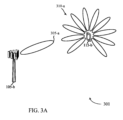
図3Aは、本開示の態様による、計測のためのビームフォーミングをサポートするワイヤレス通信システム301の一例を示す。ワイヤレス通信システム301は、図1および図2を参照しながら説明したUE115および基地局105の例であり得る、UE115-bと基地局105-bとを含み得る。UE115-bおよび基地局105-bは、ビームを使用して通信し得、たとえば、mmWスペクトルを使用して動作し得る。たとえば、基地局105-bは、指向性ビーム305-aを使用して、信号(たとえば、基準信号)を送信または受信し得る。この例では、UE115-bは、基地局105-bとの基準信号の送信または受信のために、全方向ビームパターン310-aを使用し得る。
FIG. 3A illustrates an example of a
ワイヤレス通信システム301では、基地局105-bは、信号品質がしきい値であるかまたはしきい値を上回る場合、ビーム305-aに関連付けられた基準信号を計測するために、全方向構成を使用するように、UE115-bに示し得る。信号品質は、RSRP、RSRQ、CQI、SNR、またはそれらの組合せに基づき得る。全方向ビームフォーミングオプションは、(たとえば、同時に、または掃引パターンを通してのいずれかで、すべての方向を使用して)全方向ビームパターン310-aを使用して、ビーム305-aに関連付けられた基準信号を受信および計測することを含み得る。場合によっては、基地局105-bは、構成メッセージにおいて全方向ビームフォーミングオプションを搬送し得、構成メッセージは、制御メッセージ(たとえば、レイヤ1/レイヤ2/レイヤ3制御メッセージ)の一部として送信され得る。
In the
いくつかの例では、基地局105-bによって使用されるビーム掃引パターンの選定は、UE115-bにおける特定の受信機ビームパターンを示すためのトリガとして働き得る。たとえば、基地局105-bは、各シンボルにおいて(たとえば、各OFDMシンボルにおいて)異なるビームを送っていることを知ることがある。このパターンは、基準信号を受信するために、全方向ビームパターン310-aを使用するように、UE115-bを構成するか、またはさもなければUE115-bに命令するように、基地局105-bをトリガし得る。いくつかの他の場合、基地局105-bは、(たとえば、UE115-bが動いているとき)UE115-bのためのビーム切替えの頻度がしきい値を超えると決定し得、続いて、全方向ビームパターン310-aを使用するように、UE115-bを構成し得る。 In some examples, the selection of the beam sweeping pattern used by the base station 105-b may act as a trigger to indicate a particular receiver beam pattern at the UE 115-b. For example, the base station 105-b may know that it is sending a different beam in each symbol (e.g., in each OFDM symbol). This pattern may trigger the base station 105-b to configure or otherwise instruct the UE 115-b to use the omni-directional beam pattern 310-a to receive a reference signal. In some other cases, the base station 105-b may determine that the frequency of beam switching for the UE 115-b exceeds a threshold (e.g., when the UE 115-b is moving) and may subsequently configure the UE 115-b to use the omni-directional beam pattern 310-a.
基地局105-bからのビームフォーミング構成の受信時に、UE115-bは、たとえば、そのときのRF状態、またはUE115-bの能力に基づいて、その構成における計測値を報告するか否かを判断する際に自律性を有し得る。たとえば、場合によっては、UE115-bは、それがモバイルであると決定し、レイテンシを低減するために、全方向モードにより適した基準信号(たとえば、MRS)のための計測値を明示的に要求し得る。一例では、第1の基地局105-bおよび第2の基地局105は、全方向ビーム305によって計測され得るMRSを、同じシンボル上で送信し得る。
Upon receiving a beamforming configuration from the base station 105-b, the UE 115-b may have autonomy in determining whether to report measurements in that configuration, for example, based on the RF conditions at the time, or the capabilities of the UE 115-b. For example, in some cases, the UE 115-b may determine that it is mobile and explicitly request measurements for a reference signal (e.g., MRS) that is more suitable for omni-directional mode to reduce latency. In one example, the first base station 105-b and the
いくつかの例では、UE115-bは、ビームフォーミング構成を受信しないことがあり、またはさもなければ、基準信号計測のために特定のビームフォーミングパターンを使用するように、基地局105-bによって命令されないことがある。その場合、UE115-bは、1つまたは複数のメトリクス(たとえば、信号の品質)に基づいて、計測報告のためにどのビームフォーミングオプションを使用するかを判断し得る。たとえば、UE115-bは、信号品質がしきい値を下回る場合、計測のために指向性ビームを使用し得、信号品質がしきい値であるかまたはしきい値を上回る場合、全方向ビームパターン310-aを使用し得る。 In some examples, the UE 115-b may not receive a beamforming configuration or may not otherwise be instructed by the base station 105-b to use a particular beamforming pattern for the reference signal measurements. In that case, the UE 115-b may determine which beamforming option to use for the measurement report based on one or more metrics (e.g., signal quality). For example, the UE 115-b may use a directional beam for the measurements if the signal quality is below a threshold and may use an omni-directional beam pattern 310-a if the signal quality is at or above the threshold.
いくつかの他の場合、UE115-bによって使用されるビームオプションは、基地局105-bによる以前の指示に基づき得る。たとえば、基地局105-bが、全方向ビームパターン310-aを使用するようにUE115-bに以前に示した場合、UE115-bは、後続の基準信号計測のために全方向ビームパターン310-aを使用し得る。場合によっては、UE115-bは、計測値に加えて、選定された基準計測モードを基地局105-bに示し得る。 In some other cases, the beam option used by the UE 115-b may be based on previous instructions by the base station 105-b. For example, if the base station 105-b previously indicated to the UE 115-b to use the omni-directional beam pattern 310-a, the UE 115-b may use the omni-directional beam pattern 310-a for subsequent reference signal measurements. In some cases, the UE 115-b may indicate the selected reference measurement mode to the base station 105-b in addition to the measurement values.
さらに、場合によっては、上記で説明したビームフォーミング技法はまた、UE115-bから基準信号を送信するためのULビームパターンを形成するコンテキストにおいても展開され得る。たとえば、UE115-bは、基地局105-bによって構成または命令される場合、UL基準信号を送信するために、全方向ビームパターン310-aを使用し得る。いくつかの例では、UE115-bは、UE115-bにおける信号品質、またはUE115-bの能力に基づいて、UL送信のために全方向ビームパターン310-aを使用するように自律的に判断し得る。 Furthermore, in some cases, the beamforming techniques described above may also be deployed in the context of forming an UL beam pattern for transmitting a reference signal from the UE 115-b. For example, the UE 115-b may use an omni-directional beam pattern 310-a to transmit a UL reference signal if configured or commanded by the base station 105-b. In some examples, the UE 115-b may autonomously decide to use an omni-directional beam pattern 310-a for UL transmissions based on the signal quality at the UE 115-b or the capabilities of the UE 115-b.
図3Bは、本開示の態様による、計測のためのビームフォーミングをサポートするワイヤレス通信システム302の一例を示す。ワイヤレス通信システム302は、図1、図2、または図3Aを参照しながら説明したUE115および基地局105の例であり得る、UE115-cと基地局105-cとを含み得る。UE115-cおよび基地局105-cは、ビームフォーミングされた通信を使用して通信し得、たとえば、mmWスペクトルを使用して動作し得る。たとえば、基地局105-cは、ビーム305-bを使用して、UE115-cに基準信号を搬送し得る。この例では、UE115-cは、基地局105-cとの基準信号の送信または受信のために、指向性ビームパターンを使用(たとえば、ビーム310-cを選択)し得る。
FIG. 3B illustrates an example of a
基地局105-cは、UE115-cにおける信号品質(たとえば、RSRP、RSRQ、CQI、SNRなど)がしきい値を下回る場合、基準信号を計測するために指向性ビームフォーミングオプションを使用するように、UE115-cに示し得る。場合によっては、基地局105-cは、構成メッセージにおいて指向性ビームフォーミングオプションを搬送し得、メッセージは、制御メッセージ(たとえば、レイヤ1/レイヤ2/レイヤ3制御メッセージ)の一部として送信され得る。いくつかの他の場合、基地局105-cは、ビームフォーミングオプションをアクティブ化または更新するために、これらの制御メッセージを使用し得る。 The base station 105-c may indicate to the UE 115-c to use the directional beamforming option to measure the reference signal if the signal quality (e.g., RSRP, RSRQ, CQI, SNR, etc.) at the UE 115-c is below a threshold. In some cases, the base station 105-c may carry the directional beamforming option in a configuration message, which may be sent as part of a control message (e.g., a Layer 1/Layer 2/Layer 3 control message). In some other cases, the base station 105-c may use these control messages to activate or update the beamforming option.
一態様では、基地局105-cは、UE115-cがその指向性受信機ビームパターンを形成するために使用するための、特定の指向性ビームフォーミングパラメータを提供し得る。たとえば、基地局105-cは、ビーム形状を指定し得、ビーム形状は、UE115-cが受信機ビーム310-cを形成するために使用するための幅、アレイ利得、ビーム方向、またはこれらのパラメータの組合せを含み得る。一例では、指向性ビームパターンのパラメータが、指定された基準信号(たとえば、SYNC信号)がビーム掃引される方向の中で、送信ビーム305-bの特定の方向に対応する好ましい受信方向として指定され得る。場合によっては、ビーム310-cは、ビーム305-bと整合されるか、またはペアにされる。 In one aspect, the base station 105-c may provide certain directional beamforming parameters for the UE 115-c to use to form its directional receiver beam pattern. For example, the base station 105-c may specify a beam shape, which may include a width, an array gain, a beam direction, or a combination of these parameters, for the UE 115-c to use to form the receiver beam 310-c. In one example, the parameters of the directional beam pattern may be specified as a preferred receive direction corresponding to a particular direction of the transmit beam 305-b among the directions in which a specified reference signal (e.g., a SYNC signal) is beam swept. In some cases, the beam 310-c is aligned or paired with the beam 305-b.
さらに、場合によっては、上記で説明したビームフォーミング技法はまた、UE115-cから基準信号を送信するためのULビームパターンを形成するコンテキストにおいても展開され得る。たとえば、UE115-cは、基地局105-cによって構成または命令される場合、UL基準信号を送信するために、指向性ビームパターンを使用(たとえば、ビーム310-cを選択)し得る。いくつかの例では、UE115-cは、UE115-cにおける信号品質、またはUE115-cの能力に基づいて、UL送信のために指向性ビームパターンを使用するように自律的に判断し得る。 Furthermore, in some cases, the beamforming techniques described above may also be deployed in the context of forming an UL beam pattern for transmitting a reference signal from the UE 115-c. For example, the UE 115-c may use a directional beam pattern (e.g., select beam 310-c) to transmit a UL reference signal when configured or instructed by the base station 105-c. In some examples, the UE 115-c may autonomously decide to use a directional beam pattern for UL transmission based on the signal quality at the UE 115-c or the capabilities of the UE 115-c.
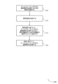
図4は、本開示の態様による、計測のための受信機ビームフォーミングのためのプロセスフロー400の一例を示す。プロセスフロー400によって示されるプロセスは、図1~図3を参照しながら説明したUE115および基地局の例であり得る、UE115-dおよび基地局105-dによって実施され得る。いくつかの例では、フロー図400によって示されるプロセスは、mmW通信を採用するワイヤレスシステムにおいて実施され得る。
FIG. 4 illustrates an
ステップ405で、接続が、UE115-dと基地局105-dとの間で確立され得る。接続を確立することは、ランダムアクセス手順を実行すること、および/またはRRCシグナリングを送信することを含み得る。基地局105-dまたはUE115-dは、接続の信号品質を決定し得る。場合によっては、信号品質は、RSRP、RSRQ、CQI、SNR、またはそれらの組合せに基づき得る。
At
ステップ410で、基地局105-dは、1つまたは複数のビームフォーミングされた基準信号を計測するために、UE115-dに要求を送信し得る。ビームフォーミングされた基準信号は、NR-SS、PSS、SSS、DMRSなどのMRS、CSI-RS、SYNC信号、またはそれらの組合せを含み得る。
In
ステップ415で、基地局105-dは、UE115-dがステップ410のビームフォーミングされた基準信号を計測するために使用するための、1つまたは複数のビームフォーミングオプション(たとえば、全方向または指向性)を、UE115-dに示し得る。場合によっては、ビームフォーミングオプションは、構成メッセージにおいて送られ得る。
In
図2および図3を参照しながら説明したように、基地局105-dは、基準信号計測のために特定の受信機ビームフォーミングパターンを使用するように、UE115-dに命令し得、命令は、構成メッセージを通して、または別個のメッセージを通して送られ得る。ビームフォーミング構成は、UE115-dにおける信号品質に基づき得る。たとえば、基地局105-dは、信号品質がしきい値であるかまたはしきい値を上回るとき、全方向構成を使用するように、および、信号品質がしきい値を下回るとき、指向性構成を使用するように、UE115-dに示し得る。 As described with reference to Figures 2 and 3, the base station 105-d may instruct the UE 115-d to use a particular receiver beamforming pattern for reference signal measurements, which may be sent through a configuration message or through a separate message. The beamforming configuration may be based on the signal quality at the UE 115-d. For example, the base station 105-d may indicate to the UE 115-d to use an omni-directional configuration when the signal quality is at or above a threshold, and to use a directional configuration when the signal quality is below the threshold.
いくつかの例では、基地局105-dのビームフォーミングされた基準信号は、別の近くの基地局105のビームフォーミングされた基準信号と重複し得るか、または基地局105-dは、UE115-dがモバイルであると決定し得る。次いで、基地局105-dは、全方向構成を使用するように、UE115-dに示し得る。
In some examples, the beamformed reference signal of the base station 105-d may overlap with the beamformed reference signal of another
指向性構成のいくつかの場合では、基地局105-dは、ビームフォーミングされた基準信号を計測するために使用するために、UE115-dに、ビーム幅、アレイ利得、ビーム方向、またはそれらの組合せを含む、ビーム形状をさらに示し得る。 In some cases of directional configurations, the base station 105-d may further indicate the beam shape, including beam width, array gain, beam direction, or a combination thereof, to the UE 115-d for use in measuring the beamformed reference signal.
さらに、場合によっては、基地局105-dは、ビームフォーミングされた基準信号を受信および計測するために、指向性構成と全方向構成の両方を使用するように、UE115-dに示し得る。いくつかの他の場合、基地局105-dは、ビームフォーミングオプションのうちの1つまたは複数をアクティブ化または非アクティブ化するために、UE115-dにメッセージを送信し得る。 Furthermore, in some cases, the base station 105-d may indicate to the UE 115-d to use both directional and omnidirectional configurations to receive and measure the beamformed reference signal. In some other cases, the base station 105-d may send messages to the UE 115-d to activate or deactivate one or more of the beamforming options.
ステップ420で、UE115-dは、その受信信号品質を計測および決定し得る。場合によっては、信号品質は、RSRP、RSRQ、CQI、SNR、またはそれらの組合せに基づき得る。ステップ405を参照しながら説明したように、信号品質は、接続確立中など、プロセスフロー中の他の時間に計測され得る。また、図2~図3を参照しながら説明したように、信号品質(または、ビーム切替え頻度など、UE115-dの他の特性)を計測するステップは、基準信号計測のためにどの受信機ビームフォーミングパターンを使用するかを示すメッセージを送るように、基地局105-dをトリガし得る。
At
ステップ425で、UE115-dは、ステップ415で受信されたビームフォーミング構成、および/またはステップ420で計測された信号品質に少なくとも部分的に基づいて、基地局105-dからビームフォーミングされた基準信号を計測および受信するためのビームフォーミング構成を決定し得る。
In
ステップ430で、基地局105-dは、UE115-dにビームフォーミングされた基準信号を送信し得る。
In
ステップ435で、UE115-dは、ステップ425で決定されたビームフォーミング受信機構成に少なくとも部分的に基づいて、ビームフォーミングされた基準信号を計測し得る。
In
ステップ440で、UE115-dは、受信された基準信号に基づいて、基地局105-dに計測報告を送信し得る。ステップ445で、UE115-dは、ビームフォーミングされた信号を受信および計測するために使用されるビームフォーミング構成を、基地局105-dに示し得る。
In
いくつかの例では、決定されたビーム構成はまた、UE115-dからの基準信号のUL送信のためにも使用され得る。たとえば、ステップ415で、基地局105-dは、どの送信ビームパターン(たとえば、全方向または指向性)をUL基準信号送信のために使用するかの指示を送り得る。
In some examples, the determined beam configuration may also be used for UL transmission of a reference signal from the UE 115-d. For example, in
図5は、本開示の態様による、計測のための受信機ビームフォーミングのためのプロセスフロー500の一例を示す。プロセスフロー500によって示されるプロセスは、図1~図3を参照しながら説明したUE115および基地局の例であり得る、UE115-eおよび基地局105-eによって実施され得る。いくつかの例では、フロー図500によって示されるプロセスは、mmW通信を採用するワイヤレスシステムにおいて実施され得る。
FIG. 5 illustrates an
ステップ505で、接続が、UE115-eと基地局105-eとの間で確立され得る。接続を確立することは、ランダムアクセス手順を実行すること、および/またはRRCシグナリングを送信することを含み得る。
At
ステップ510で、基地局105-eは、1つまたは複数のビームフォーミングされた基準信号を計測するために、UE115-eに要求を送信し得る。ビームフォーミングされた基準信号は、MRS、CSI-RS、SYNC、またはそれらの組合せを含み得る。
At
ステップ515で、UE115-eは、その受信信号品質を計測および決定し得る。場合によっては、信号品質は、RSRP、RSRQ、CQI、SNR、またはそれらの組合せに基づき得る。
At
ステップ520で、UE115-eは、ステップ515で計測された信号品質に少なくとも部分的に基づいて、基地局105-eからビームフォーミングされた基準信号を計測および受信するためのビームフォーミング構成を決定し得る。すなわち、UE115-eは、最初に基地局105-eから指示または命令を受信することなしに、どの受信機ビームパターンを使用するかを決定し得る(たとえば、自律的決定)。場合によっては、UE115-eは、信号品質がしきい値を下回る場合、計測のために指向性構成を使用し得、信号品質がしきい値であるかまたはしきい値を上回る場合、全方向構成を使用し得る。いくつかの他の場合、UE115-eによって使用される受信機ビーム構成は、基地局105-eによる以前の指示、またはUE115-eの他の特性(たとえば、図2~図3を参照しながら説明したように、ビーム切替えの頻度、または使用されているビーム掃引パターン)に基づき得る。
In
ステップ525で、基地局105-eは、UE115-eにビームフォーミングされた基準信号を送信し得る。
In
ステップ530で、UE115-eは、ステップ520で決定された受信機ビームフォーミング構成に少なくとも部分的に基づいて、ビームフォーミングされた基準信号を計測し得る。
In
ステップ535で、UE115-eは、ステップ525で受信された基準信号に基づいて、基地局105-eに計測報告を送信し得る。
In
ステップ540で、UE115-eは、ビームフォーミングされた基準信号を受信および計測するために使用されるビームフォーミング構成を、基地局105-eに示し得る。
In
いくつかの例では、決定されたビーム構成はまた、UE115-eからの基準信号のUL送信のためにも使用され得る。たとえば、ステップ520で、UE115-eは、どの送信ビームパターン(たとえば、全方向または指向性)をUL基準信号送信のために使用するかを自律的に決定し得る。
In some examples, the determined beam configuration may also be used for UL transmission of a reference signal from UE 115-e. For example, in
図6は、本開示の様々な態様による、計測のための受信機ビームフォーミングをサポートするワイヤレスデバイス605のブロック図600を示す。ワイヤレスデバイス605は、図1を参照しながら説明したような、UE115または基地局105の態様の一例であり得る。ワイヤレスデバイス605は、受信機610と、ビームフォーミングマネージャ615と、送信機620とを含み得る。ワイヤレスデバイス605はまた、プロセッサを含み得る。これらの構成要素の各々は、(たとえば、1つまたは複数のバスを介して)互いに通信中であり得る。
FIG. 6 illustrates a block diagram 600 of a
受信機610は、パケット、ユーザデータ、または様々な情報チャネル(たとえば、制御チャネル、データチャネル、および計測のための受信機ビームフォーミングに関する情報など)に関連付けられた制御情報などの情報を受信し得る。情報は、デバイスの他の構成要素に渡され得る。受信機610は、図9を参照しながら説明するトランシーバ935の態様の一例であり得る。
The
ビームフォーミングマネージャ615は、図9を参照しながら説明するビームフォーミングマネージャ915の態様の一例であり得る。
The
ビームフォーミングマネージャ615は、ビームフォーミングされた基準信号を計測するための要求を送信し得る。さらに、ビームフォーミングマネージャ615は、ビームフォーミングされた基準信号を計測するための1つまたは複数のビームフォーミングオプションを示す、ビームフォーミング構成を送信することであって、1つまたは複数のビームフォーミングオプションが、指向性構成と全方向構成とを使用して、ビームフォーミングされた基準信号を計測することを含む、ことを行い得る。
The
ビームフォーミングマネージャ615はまた、ビームフォーミングされた基準信号を計測するための要求を受信し得る。さらに、ビームフォーミングマネージャ615は、ビームフォーミングされた基準信号を計測するための1つまたは複数のビームフォーミングオプションを示す、ビームフォーミング構成を受信し得、その場合、1つまたは複数のビームフォーミングオプションは、指向性構成と全方向構成とを使用して、ビームフォーミングされた基準信号を計測することを含む。
The
場合によっては、ビームフォーミングマネージャ615は、ビームフォーミング構成に基づいて、指向性構成または全方向構成を使用するように決定すること、および、決定に基づいて、ビームフォーミングされた基準信号を計測することを行い得る。
In some cases, the
ビームフォーミングマネージャ615はまた、ビームフォーミングされた基準信号を計測するための要求を受信すること、信号品質を決定すること、信号品質に基づいて、ビームフォーミングされた基準信号を計測するために、指向性構成または全方向構成を使用するように決定すること、および、決定に基づいて、ビームフォーミングされた基準信号を計測することを行い得る。
The
送信機620は、デバイスの他の構成要素によって生成された信号を送信し得る。いくつかの例では、送信機620は、トランシーバモジュールにおいて受信機610とコロケートされ得る。たとえば、送信機620は、図9を参照しながら説明するトランシーバ935の態様の一例であり得る。送信機620は、単一のアンテナを含み得るか、またはアンテナのセットを含み得る。さらに、場合によっては、送信機620は、ビームフォーミングされた基準信号を送信し得る。
The
図7は、本開示の様々な態様による、計測のための受信機ビームフォーミングをサポートするワイヤレスデバイス705のブロック図700を示す。ワイヤレスデバイス705は、図1および図6を参照しながら説明したような、ワイヤレスデバイス605、またはUE115、または基地局105の態様の一例であり得る。ワイヤレスデバイス705は、受信機710と、ビームフォーミングマネージャ715と、送信機720とを含み得る。ワイヤレスデバイス705はまた、プロセッサを含み得る。これらの構成要素の各々は、(たとえば、1つまたは複数のバスを介して)互いに通信中であり得る。
FIG. 7 illustrates a block diagram 700 of a
受信機710は、パケット、ユーザデータ、または様々な情報チャネル(たとえば、制御チャネル、データチャネル、および計測のための受信機ビームフォーミングに関する情報など)に関連付けられた制御情報などの情報を受信し得る。情報は、デバイスの他の構成要素に渡され得る。受信機710は、図9を参照しながら説明するトランシーバ935の態様の一例であり得る。
The
ビームフォーミングマネージャ715は、図9を参照しながら説明するビームフォーミングマネージャ915の態様の一例であり得る。
The
ビームフォーミングマネージャ715はまた、計測要求構成要素725と、ビームフォーミング構成構成要素730と、ビームフォーミング決定構成要素735と、基準信号計測構成要素740と、信号品質構成要素745とを含み得る。
The
計測要求構成要素725は、ビームフォーミングされた基準信号を計測するための要求を送信すること、および、ビームフォーミングされた基準信号を計測するための要求を受信することを行い得る。場合によっては、ビームフォーミングされた基準信号は、MRS、CSI-RS、SYNC信号、またはそれらの組合せを含む。
The
ビームフォーミング構成構成要素730は、ビームフォーミングされた基準信号を計測するための1つまたは複数のビームフォーミングオプションを示す、ビームフォーミング構成を送信することであって、1つまたは複数のビームフォーミングオプションが、指向性構成と全方向構成とを使用して、ビームフォーミングされた基準信号を計測することを含む、ことを行い得る。
The
いくつかの他の場合、ビームフォーミング構成構成要素730は、ビームフォーミングされた基準信号を計測するための1つまたは複数のビームフォーミングオプションを示す、ビームフォーミング構成を受信し得、その場合、1つまたは複数のビームフォーミングオプションは、指向性構成と全方向構成とを使用して、ビームフォーミングされた基準信号を計測することを含む。
In some other cases, the
ビームフォーミング決定構成要素735は、ビームフォーミング構成に基づいて、指向性構成または全方向構成を使用するように決定し得る。ビームフォーミング決定構成要素735はまた、ビームフォーミングされた基準信号を計測するために、指向性構成が使用されたか、全方向構成が使用されたかを示す、メッセージを送信し得る。
The
いくつかの他の場合、ビームフォーミング決定構成要素735は、信号品質に基づいて、ビームフォーミングされた基準信号を計測するために、指向性構成または全方向構成を使用するように決定し得る。さらに、場合によっては、ビームフォーミング決定構成要素735は、信号品質がしきい値であるかまたはしきい値を上回る場合、全方向構成を使用するように、および、信号品質がしきい値を下回る場合、指向性構成を使用するように決定し得る。たとえば、ビームフォーミング決定構成要素735は、全方向構成または指向性構成を使用中に計測されたUEにおける信号品質がしきい値を下回る場合、計測のために指向性ビームを使用するように判断し得る。他の場合、ビームフォーミング決定構成要素735は、全方向構成または指向性構成を使用中に計測されたUEにおける信号品質がしきい値であるかまたはしきい値を上回る場合、計測のために全方向ビームを使用するように判断し得る。
In some other cases, the
基準信号計測構成要素740は、決定に基づいて、ビームフォーミングされた基準信号を計測し得る。
The reference
信号品質構成要素745は、信号品質を決定し得る。場合によっては、信号品質は、RSRP、RSRQ、CQI、SNR、またはそれらの組合せに基づく。
The
送信機720は、デバイスの他の構成要素によって生成された信号を送信し得る。いくつかの例では、送信機720は、トランシーバモジュールにおいて受信機710とコロケートされ得る。たとえば、送信機720は、図9を参照しながら説明するトランシーバ935の態様の一例であり得る。送信機720は、単一のアンテナを含み得るか、またはアンテナのセットを含み得る。
The
図8は、本開示の様々な態様による、計測のための受信機ビームフォーミングをサポートするビームフォーミングマネージャ815のブロック図800を示す。ビームフォーミングマネージャ815は、図6、図7、および図9を参照しながら説明するビームフォーミングマネージャ615、ビームフォーミングマネージャ715、またはビームフォーミングマネージャ915の態様の一例であり得る。ビームフォーミングマネージャ815は、計測要求構成要素820と、ビームフォーミング構成構成要素825と、ビームフォーミング決定構成要素830と、基準信号計測構成要素835と、信号品質構成要素840と、ビームフォーミング指示構成要素845と、ビームフォーミングアクティベーション構成要素850と、ビームフォーミング要求構成要素855とを含み得る。これらのモジュールの各々は、(たとえば、1つまたは複数のバスを介して)互いに直接または間接的に通信し得る。
FIG. 8 illustrates a block diagram 800 of a
計測要求構成要素820は、ビームフォーミングされた基準信号を計測するための要求を送信すること、および、ビームフォーミングされた基準信号を計測するための要求を受信することを行い得る。場合によっては、ビームフォーミングされた基準信号は、NR-SS、PSS、SSS、DMRSなどのMRS、CSI-RS、SYNC信号、またはそれらの組合せを含む。
The
ビームフォーミング構成構成要素825は、ビームフォーミングされた基準信号を計測するための1つまたは複数のビームフォーミングオプションを示す、ビームフォーミング構成を送信し得、その場合、1つまたは複数のビームフォーミングオプションが、指向性構成と全方向構成とを使用して、ビームフォーミングされた基準信号を計測することを含む。
The
いくつかの他の場合、ビームフォーミング構成構成要素825は、ビームフォーミングされた基準信号を計測するための1つまたは複数のビームフォーミングオプションを示す、ビームフォーミング構成を受信し得、その場合、1つまたは複数のビームフォーミングオプションは、指向性構成と全方向構成とを使用して、ビームフォーミングされた基準信号を計測することを含む。
In some other cases, the
ビームフォーミング決定構成要素830は、ビームフォーミング構成に基づいて、指向性構成または全方向構成を使用するように決定すること、ビームフォーミングされた基準信号を計測するために、指向性構成が使用されたか、全方向構成が使用されたかを示す、メッセージを送信することを行い得る。
The
いくつかの他の場合、ビームフォーミング決定構成要素830は、信号品質に基づいて、ビームフォーミングされた基準信号を計測するために、指向性構成または全方向構成を使用するように決定し得る。さらに、場合によっては、ビームフォーミング決定構成要素830は、信号品質がしきい値であるかまたはしきい値を上回る場合、全方向構成を使用するように、および、信号品質がしきい値を下回る場合、指向性構成を使用するように決定し得る。たとえば、ビームフォーミング決定構成要素830は、全方向構成または指向性構成を使用中に計測されたUEにおける信号品質がしきい値を下回る場合、計測のために指向性ビームを使用するように判断し得る。他の場合、ビームフォーミング決定構成要素830は、全方向構成または指向性構成を使用中に計測されたUEにおける信号品質がしきい値であるかまたはしきい値を上回る場合、計測のために全方向ビームを使用するように判断し得る。
In some other cases, the
基準信号計測構成要素835は、決定に基づいて、ビームフォーミングされた基準信号を計測し得る。
The reference
信号品質構成要素840は、信号品質を決定し得る。場合によっては、信号品質は、RSRP、RSRQ、CQI、SNR、またはそれらの組合せに基づく。
The
ビームフォーミング指示構成要素845は、ビームフォーミングされた基準信号を計測するために、指向性構成を使用するか、全方向構成を使用するかの指示を送信し得る。場合によっては、ビームフォーミング指示構成要素845は、ビーム切替えの頻度がしきい値であるかまたはしきい値を上回ると決定し得、その場合、指示は、全方向構成の使用を示す。
The
いくつかの他の場合、ビームフォーミング指示構成要素845は、ビームフォーミングされた基準信号を計測するために、指向性構成を使用するか、全方向構成を使用するかの指示を受信し得る。さらに、場合によっては、ビームフォーミング指示構成要素845は、指示が全方向構成の使用を示す場合、指向性構成を使用するように、または、指示が全方向構成の使用を示す場合、指向性構成を使用するように決定し得る。
In some other cases, the
場合によっては、指示は、信号品質がしきい値であるかまたはしきい値を上回るとき、全方向構成の使用を示し、信号品質がしきい値を下回るとき、指向性構成の使用を示す。場合によっては、信号品質は、RSRP、RSRQ、CQI、SNR、またはそれらの組合せに基づく。場合によっては、指示は、ビームフォーミングされた基準信号を計測するために使用するためのビーム形状を示し、その場合、ビーム形状は、ビーム幅、アレイ利得、ビーム方向、またはそれらの組合せを含む。 In some cases, the instructions indicate use of an omni-directional configuration when the signal quality is at or above a threshold, and indicate use of a directional configuration when the signal quality is below the threshold. In some cases, the signal quality is based on RSRP, RSRQ, CQI, SNR, or a combination thereof. In some cases, the instructions indicate a beam shape to use to measure the beamformed reference signal, where the beam shape includes a beam width, an array gain, a beam direction, or a combination thereof.
場合によっては、ビームフォーミングされた基準信号が近隣の送信機からの基準信号と重複するとき、指示は、全方向構成の使用を示す。場合によっては、指示は、指向性構成と全方向構成の両方の使用を示す。場合によっては、指示は、全方向構成の使用を示すために、シンボルのセットにおいて反復基準信号を含む、ビーム掃引パターンを含む。 In some cases, the indications indicate the use of an omni-directional configuration when the beamformed reference signal overlaps with a reference signal from a nearby transmitter. In some cases, the indications indicate the use of both directional and omni-directional configurations. In some cases, the indications include a beam sweep pattern that includes a repeating reference signal in the set of symbols to indicate the use of an omni-directional configuration.
ビームフォーミングアクティベーション構成要素850は、1つまたは複数のビームフォーミングオプションをアクティブ化または非アクティブ化するためのアクティベーションメッセージを送信し得る。
The
ビームフォーミング要求構成要素855は、全方向構成に適合する基準信号ビーム掃引タイプを要求する構成要求を送信し得る。
The
図9は、本開示の様々な態様による、計測のための受信機ビームフォーミングをサポートするデバイス905を含むシステム900の図を示す。デバイス905は、たとえば、図1、図6、および図7を参照しながら上記で説明したような、ワイヤレスデバイス605、ワイヤレスデバイス705、またはUE115の構成要素の一例であり得るか、またはそれらの構成要素を含み得る。デバイス905は、UEビームフォーミングマネージャ915と、プロセッサ920と、メモリ925と、ソフトウェア930と、トランシーバ935と、アンテナ940と、I/Oコントローラ945とを含む、通信を送信および受信するための構成要素を含む、双方向音声およびデータ通信のための構成要素を含み得る。これらの構成要素は、1つまたは複数のバス(たとえば、バス910)を介して電子通信し得る。デバイス905は、1つまたは複数の基地局105とワイヤレス通信し得る。
FIG. 9 illustrates a diagram of a
プロセッサ920は、インテリジェントハードウェアデバイス(たとえば、汎用プロセッサ、デジタル信号プロセッサ(DSP)、中央処理ユニット(CPU)、マイクロコントローラ、特定用途向け集積回路(ASIC)、フィールドプログラマブルゲートアレイ(FPGA)、プログラマブル論理デバイス、個別ゲートもしくはトランジスタ論理構成要素、個別ハードウェア構成要素、またはそれらの任意の組合せ)を含み得る。場合によっては、プロセッサ920は、メモリコントローラを使用して、メモリアレイを動作させるように構成され得る。他の場合には、メモリコントローラは、プロセッサ920に統合され得る。プロセッサ920は、様々な機能(たとえば、計測のための受信機ビームフォーミングをサポートする機能またはタスク)を実行するために、メモリ内に記憶されたコンピュータ可読命令を実行するように構成され得る。
The
メモリ925は、ランダムアクセスメモリ(RAM)および読取り専用メモリ(ROM)を含み得る。メモリ925は、実行されると、プロセッサに、本明細書で説明する様々な機能を実行させる命令を含む、コンピュータ可読、コンピュータ実行可能ソフトウェア930を記憶し得る。場合によっては、メモリ925は、とりわけ、周辺構成要素またはデバイスとの相互作用などの基本的なハードウェア動作および/またはソフトウェア動作を制御し得る基本入出力システム(BIOS)を含み得る。
ソフトウェア930は、計測のための受信機ビームフォーミングをサポートするためのコードを含め、本開示の態様を実装するためのコードを含み得る。ソフトウェア930は、システムメモリまたは他のメモリなど、非一時的コンピュータ可読媒体内に記憶され得る。場合によっては、ソフトウェア930は、プロセッサによって直接実行可能ではないことがあるが、(たとえば、コンパイルされ、実行されると)本明細書で説明する機能をコンピュータに実行させ得る。
The
トランシーバ935は、上記で説明したように、1つまたは複数のアンテナ、ワイヤードリンク、またはワイヤレスリンクを介して双方向に通信し得る。たとえば、トランシーバ935は、ワイヤレストランシーバを表すことがあり、別のワイヤレストランシーバと双方向に通信し得る。トランシーバ935はまた、パケットを変調し、変調されたパケットを送信のためにアンテナに提供するために、かつアンテナから受信されたパケットを復調するために、モデムを含み得る。
The
場合によっては、ワイヤレスデバイスは、単一のアンテナ940を含み得る。しかしながら、場合によっては、デバイスは、複数のワイヤレス送信を同時に送信または受信することが可能であり得る、2つ以上のアンテナ940を有し得る。
In some cases, a wireless device may include a
I/Oコントローラ945は、デバイス905のための入力信号および出力信号を管理し得る。I/Oコントローラ945はまた、デバイス905に統合されていない周辺装置を管理し得る。場合によっては、I/Oコントローラ945は、外部周辺装置への物理接続またはポートを表すことがある。場合によっては、I/Oコントローラ945は、iOS(登録商標)、ANDROID(登録商標)、MS-DOS(登録商標)、MS-WINDOWS(登録商標)、OS/2(登録商標)、UNIX(登録商標)、LINUX(登録商標)、または別の知られているオペレーティングシステムなどの、オペレーティングシステムを利用し得る。
The I/
図10は、本開示の様々な態様による、計測のための受信機ビームフォーミングをサポートするデバイス1005を含むシステム1000の図を示す。デバイス1005は、たとえば、図1、図6、および図7を参照しながら上記で説明したような、ワイヤレスデバイス605、ワイヤレスデバイス705、または基地局105の構成要素の一例であり得るか、またはそれらの構成要素を含み得る。デバイス1005は、基地局ビームフォーミングマネージャ1015と、プロセッサ1020と、メモリ1025と、ソフトウェア1030と、トランシーバ1035と、アンテナ1040と、ネットワーク通信マネージャ1045と、基地局通信マネージャ1050とを含む、通信を送信および受信するための構成要素を含む、双方向音声およびデータ通信のための構成要素を含み得る。これらの構成要素は、1つまたは複数のバス(たとえば、バス1010)を介して電子通信し得る。デバイス1005は、1つまたは複数のUE115とワイヤレス通信し得る。
FIG. 10 illustrates a diagram of a
プロセッサ1020は、インテリジェントハードウェアデバイス(たとえば、汎用プロセッサ、DSP、CPU、マイクロコントローラ、ASIC、FPGA、プログラマブル論理デバイス、個別ゲートもしくはトランジスタ論理構成要素、個別ハードウェア構成要素、またはそれらの任意の組合せ)を含み得る。場合によっては、プロセッサ1020は、メモリコントローラを使用して、メモリアレイを動作させるように構成され得る。他の場合には、メモリコントローラは、プロセッサ1020に統合され得る。プロセッサ1020は、様々な機能(たとえば、計測のための受信機ビームフォーミングをサポートする機能またはタスク)を実行するために、メモリ内に記憶されたコンピュータ可読命令を実行するように構成され得る。
The
メモリ1025は、RAMおよびROMを含み得る。メモリ1025は、実行されると、プロセッサに、本明細書で説明する様々な機能を実行させる命令を含む、コンピュータ可読、コンピュータ実行可能ソフトウェア1030を記憶し得る。場合によっては、メモリ1025は、とりわけ、周辺構成要素またはデバイスとの相互作用などの基本的なハードウェア動作および/またはソフトウェア動作を制御し得るBIOSを含み得る。
ソフトウェア1030は、計測のための受信機ビームフォーミングをサポートするためのコードを含め、本開示の態様を実装するためのコードを含み得る。ソフトウェア1030は、システムメモリまたは他のメモリなど、非一時的コンピュータ可読媒体内に記憶され得る。場合によっては、ソフトウェア1030は、プロセッサによって直接実行可能ではないことがあるが、(たとえば、コンパイルされ、実行されると)本明細書で説明する機能をコンピュータに実行させ得る。
The
トランシーバ1035は、上記で説明したように、1つまたは複数のアンテナ、ワイヤードリンク、またはワイヤレスリンクを介して双方向に通信し得る。たとえば、トランシーバ1035は、ワイヤレストランシーバを表すことがあり、別のワイヤレストランシーバと双方向に通信し得る。トランシーバ1035はまた、パケットを変調し、変調されたパケットを送信のためにアンテナに提供するために、かつアンテナから受信されたパケットを復調するために、モデムを含み得る。
The
場合によっては、ワイヤレスデバイスは、単一のアンテナ1040を含み得る。しかしながら、場合によっては、デバイスは、複数のワイヤレス送信を同時に送信または受信することが可能であり得る、2つ以上のアンテナ1040を有し得る。
In some cases, a wireless device may include a
ネットワーク通信マネージャ1045は、(たとえば、1つまたは複数のワイヤードバックホールリンクを介して)コアネットワークとの通信を管理し得る。たとえば、ネットワーク通信マネージャ1045は、1つまたは複数のUE115などのクライアントデバイスのためのデータ通信の転送を管理し得る。
The
基地局通信マネージャ1050は、他の基地局105との通信を管理し得、他の基地局105と協調してUE115との通信を制御するためのコントローラまたはスケジューラを含み得る。たとえば、基地局通信マネージャ1050は、ビームフォーミングまたはジョイント送信などの様々な干渉緩和技法のために、UE115への送信のためのスケジューリングを協調させ得る。いくつかの例では、基地局通信マネージャ1050は、基地局105間で通信を行うために、LTE/LTE-Aワイヤレス通信ネットワーク技術内のX2インターフェースを提供し得る。
The base
図11は、本開示の様々な態様による、計測のための受信機ビームフォーミングのための方法1100を示すフローチャートを示す。方法1100の動作は、本明細書で説明したようなUE115または基地局105またはその構成要素によって実施され得る。たとえば、方法1100の動作は、図6~図8を参照しながら説明したように、ビームフォーミングマネージャによって実行され得る。いくつかの例では、UE115または基地局105は、以下で説明する機能を実行するようにデバイスの機能要素を制御するためのコードのセットを実行し得る。追加または代替として、UE115または基地局105は、専用ハードウェアを使用して、以下で説明する機能の態様を実行し得る。
FIG. 11 illustrates a flow chart illustrating a
ブロック1105で、UE115または基地局105は、ビームフォーミングされた基準信号を計測するための要求を送信し得る。ブロック1105の動作は、図1~図5を参照しながら説明した方法に従って実行され得る。いくつかの例では、ブロック1105の動作の態様は、図6~図8を参照しながら説明したように、計測要求構成要素によって実行され得る。
At
ブロック1110で、UE115または基地局105は、ビームフォーミングされた基準信号を計測するための1つまたは複数のビームフォーミングオプションを示す、ビームフォーミング構成を送信することであって、1つまたは複数のビームフォーミングオプションが、ビームフォーミングされた基準信号を計測するためのビームパターンの指示を含む、ことを行い得る。場合によっては、1つまたは複数のビームフォーミングオプションは、ビームフォーミングされた基準信号を計測するために、指向性構成、全方向構成、または組合せを使用することをさらに含み得る。ブロック1110の動作は、図1~図5を参照しながら説明した方法に従って実行され得る。いくつかの例では、ブロック1110の動作の態様は、図6~図8を参照しながら説明したように、ビームフォーミング構成構成要素によって実行され得る。
At
ブロック1115で、UE115または基地局105は、ビームフォーミングされた基準信号を送信し得る。ブロック1115の動作は、図1~図5を参照しながら説明した方法に従って実行され得る。いくつかの例では、ブロック1115の動作の態様は、図6~図8を参照しながら説明したように、送信機によって実行され得る。
At
図12は、本開示の様々な態様による、計測のための受信機ビームフォーミングのための方法1200を示すフローチャートを示す。方法1200の動作は、本明細書で説明したようなUE115または基地局105またはその構成要素によって実施され得る。たとえば、方法1200の動作は、図6~図8を参照しながら説明したように、ビームフォーミングマネージャによって実行され得る。いくつかの例では、UE115または基地局105は、以下で説明する機能を実行するようにデバイスの機能要素を制御するためのコードのセットを実行し得る。追加または代替として、UE115または基地局105は、専用ハードウェアを使用して、以下で説明する機能の態様を実行し得る。
FIG. 12 illustrates a flow chart illustrating a
ブロック1205で、UE115または基地局105は、ビームフォーミングされた基準信号を計測するための要求を受信し得る。ブロック1205の動作は、図1~図5を参照しながら説明した方法に従って実行され得る。いくつかの例では、ブロック1205の動作の態様は、図6~図8を参照しながら説明したように、計測要求構成要素によって実行され得る。
At
ブロック1210で、UE115または基地局105は、ビームフォーミングされた基準信号を計測するための1つまたは複数のビームフォーミングオプションを示す、ビームフォーミング構成を受信し得、ここにおいて、1つまたは複数のビームフォーミングオプションが、ビームフォーミングされた基準信号を計測するためのビームパターンの指示を含む。場合によっては、1つまたは複数のビームフォーミングオプションは、ビームフォーミングされた基準信号を計測するために、指向性構成、全方向構成、または組合せを使用することをさらに含み得る。ブロック1210の動作は、図1~図5を参照しながら説明した方法に従って実行され得る。いくつかの例では、ブロック1210の動作の態様は、図6~図8を参照しながら説明したように、ビームフォーミング構成構成要素によって実行され得る。
At
ブロック1215で、UE115または基地局105は、ビームフォーミング構成に少なくとも部分的に基づいて、指向性構成または全方向構成を使用するように決定し得る。ブロック1215の動作は、図1~図5を参照しながら説明した方法に従って実行され得る。いくつかの例では、ブロック1215の動作の態様は、図6~図8を参照しながら説明したように、ビームフォーミング決定構成要素によって実行され得る。
At
ブロック1220で、UE115または基地局105は、決定に少なくとも部分的に基づいて、ビームフォーミングされた基準信号を計測し得る。ブロック1220の動作は、図1~図5を参照しながら説明した方法に従って実行され得る。いくつかの例では、ブロック1220の動作の態様は、図6~図8を参照しながら説明したように、基準信号計測構成要素によって実行され得る。
At
図13は、本開示の様々な態様による、計測のための受信機ビームフォーミングのための方法1300を示すフローチャートを示す。方法1300の動作は、本明細書で説明したようなUE115または基地局105またはその構成要素によって実施され得る。たとえば、方法1300の動作は、図6~図8を参照しながら説明したように、ビームフォーミングマネージャによって実行され得る。いくつかの例では、UE115または基地局105は、以下で説明する機能を実行するようにデバイスの機能要素を制御するためのコードのセットを実行し得る。追加または代替として、UE115または基地局105は、専用ハードウェアを使用して、以下で説明する機能の態様を実行し得る。
FIG. 13 illustrates a flow chart illustrating a
ブロック1305で、UE115または基地局105は、ビームフォーミングされた基準信号を計測するための要求を受信し得る。ブロック1305の動作は、図1~図5を参照しながら説明した方法に従って実行され得る。いくつかの例では、ブロック1305の動作の態様は、図6~図8を参照しながら説明したように、計測要求構成要素によって実行され得る。
At
ブロック1310で、UE115または基地局105は、信号品質を決定し得る。ブロック1310の動作は、図1~図5を参照しながら説明した方法に従って実行され得る。いくつかの例では、ブロック1310の動作の態様は、図6~図8を参照しながら説明したように、信号品質構成要素によって実行され得る。
At
ブロック1315で、UE115または基地局105は、信号品質に少なくとも部分的に基づいて、ビームフォーミングされた基準信号を計測するために、指向性構成または全方向構成を使用するように決定し得る。ブロック1315の動作は、図1~図5を参照しながら説明した方法に従って実行され得る。いくつかの例では、ブロック1315の動作の態様は、図6~図8を参照しながら説明したように、ビームフォーミング決定構成要素によって実行され得る。
At
ブロック1320で、UE115または基地局105は、決定に少なくとも部分的に基づいて、ビームフォーミングされた基準信号を計測し得る。ブロック1320の動作は、図1~図5を参照しながら説明した方法に従って実行され得る。いくつかの例では、ブロック1320の動作の態様は、図6~図8を参照しながら説明したように、基準信号計測構成要素によって実行され得る。
At
上記で説明した方法は、可能な実装形態について説明しており、動作およびステップは、並べ替えられるか、または他の方法で修正されてもよく、他の実装形態が可能であることに留意されたい。さらに、方法のうちの2つ以上からの態様が組み合わせられてよい。 It should be noted that the methods described above describe possible implementations, and that the operations and steps may be rearranged or otherwise modified, and other implementations are possible. Additionally, aspects from two or more of the methods may be combined.
本明細書で説明した技法は、符号分割多元接続(CDMA)、時分割多元接続(TDMA)、周波数分割多元接続(FDMA)、直交周波数分割多元接続(OFDMA)、シングルキャリア周波数分割多元接続(SC-FDMA)、および他のシステムなどの、様々なワイヤレス通信システムのために使用され得る。「システム」および「ネットワーク」という用語は、しばしば、互換的に使用される。符号分割多元接続(CDMA)システムは、CDMA2000、ユニバーサル地上波無線アクセス(UTRA)などの無線技術を実装し得る。CDMA2000は、IS-2000規格、IS-95規格、およびIS-856規格を対象とする。IS-2000リリースは、通常、CDMA2000 1X、1Xなどと呼ばれることがある。IS-856(TIA-856)は、一般に、CDMA2000 1xEV-DO、高速パケットデータ(HRPD)などと呼ばれる。UTRAは、広帯域CDMA(WCDMA(登録商標))、およびCDMAの他の変形態を含む。時分割多元接続(TDMA)システムは、モバイル通信用グローバルシステム(GSM(登録商標))などの無線技術を実装し得る。 The techniques described herein may be used for various wireless communication systems, such as Code Division Multiple Access (CDMA), Time Division Multiple Access (TDMA), Frequency Division Multiple Access (FDMA), Orthogonal Frequency Division Multiple Access (OFDMA), Single Carrier Frequency Division Multiple Access (SC-FDMA), and other systems. The terms "system" and "network" are often used interchangeably. Code Division Multiple Access (CDMA) systems may implement radio technologies such as CDMA2000, Universal Terrestrial Radio Access (UTRA), and the like. CDMA2000 covers IS-2000, IS-95, and IS-856 standards. IS-2000 releases are sometimes commonly referred to as CDMA2000 1X, 1X, and the like. IS-856 (TIA-856) is commonly referred to as CDMA2000 1xEV-DO, High Rate Packet Data (HRPD), and the like. UTRA includes Wideband CDMA (WCDMA) and other variants of CDMA. Time Division Multiple Access (TDMA) systems may implement radio technologies such as Global System for Mobile Communications (GSM).
直交周波数分割多元接続(OFDMA)システムは、ウルトラモバイルブロードバンド(UMB)、発展型UTRA(E-UTRA)、米国電気電子技術者協会(IEEE)802.11(Wi-Fi)、IEEE802.16(WiMAX)、IEEE802.20、Flash-OFDMなどの無線技術を実装し得る。UTRAおよびE-UTRAは、ユニバーサルモバイルテレコミュニケーションズシステム(UMTS)の一部である。3GPPロングタームエボリューション(LTE)およびLTEアドバンスト(LTE-A)は、E-UTRAを使用するユニバーサルモバイルテレコミュニケーションズシステム(UMTS)のリリースである。UTRA、E-UTRA、UMTS、LTE、LTE-A、NR、およびモバイル通信用グローバルシステム(GSM(登録商標))は、「第3世代パートナーシッププロジェクト」(3GPP)と称する組織からの文書に記載されている。CDMA2000およびUMBは、「第3世代パートナーシッププロジェクト2」(3GPP2)と称する組織からの文書に記載されている。本明細書で説明した技法は、上述のシステムおよび無線技術、ならびに他のシステムおよび無線技術のために使用され得る。LTEまたはNRシステムの態様が例として説明されることがあり、説明の大部分においてLTEまたはNR用語が使用されることがあるが、本明細書で説明した技法はLTEまたはNR適用例以外に適用可能である。 Orthogonal Frequency Division Multiple Access (OFDMA) systems may implement radio technologies such as Ultra Mobile Broadband (UMB), Evolved UTRA (E-UTRA), Institute of Electrical and Electronics Engineers (IEEE) 802.11 (Wi-Fi), IEEE 802.16 (WiMAX), IEEE 802.20, Flash-OFDM, and others. UTRA and E-UTRA are parts of the Universal Mobile Telecommunications System (UMTS). 3GPP Long Term Evolution (LTE) and LTE-Advanced (LTE-A) are releases of the Universal Mobile Telecommunications System (UMTS) that use E-UTRA. UTRA, E-UTRA, UMTS, LTE, LTE-A, NR, and Global System for Mobile Communications (GSM) are described in documents from an organization named "3rd Generation Partnership Project" (3GPP). CDMA2000 and UMB are described in documents from an organization named "3rd Generation Partnership Project 2" (3GPP2). The techniques described herein may be used for the systems and radio technologies mentioned above, as well as other systems and radio technologies. Although aspects of an LTE or NR system may be described as an example, and LTE or NR terminology may be used throughout much of the description, the techniques described herein are applicable to other than LTE or NR applications.
本明細書で説明するそのようなネットワークを含むLTE/LTE-Aネットワークでは、発展型ノードB(eNB)という用語は、概して、基地局を表すために使用され得る。本明細書で説明する1つまたは複数のワイヤレス通信システムは、異なるタイプの発展型ノードB(eNB)が様々な地理的領域にカバレージを提供する、異種LTE/LTE-AまたはNRネットワークを含み得る。たとえば、各eNB、gNB、または基地局は、マクロセル、スモールセル、または他のタイプのセルのための通信カバレージを提供し得る。「セル」という用語は、文脈に応じて、基地局、基地局に関連付けられるキャリアもしくはコンポーネントキャリア、またはキャリアもしくは基地局のカバレージエリア(たとえば、セクタなど)を表すために使用され得る。 In LTE/LTE-A networks, including such networks described herein, the term evolved Node B (eNB) may be used generally to refer to a base station. One or more wireless communications systems described herein may include heterogeneous LTE/LTE-A or NR networks in which different types of evolved Node Bs (eNBs) provide coverage for various geographic regions. For example, each eNB, gNB, or base station may provide communication coverage for a macro cell, a small cell, or other type of cell. The term "cell" may be used to refer to a base station, a carrier or component carrier associated with a base station, or a coverage area (e.g., a sector, etc.) of a carrier or base station, depending on the context.
基地局は、基地トランシーバ局、無線基地局、アクセスポイント、無線トランシーバ、ノードB、eノードB(eNB)、次世代ノードB(gNB)、ホームノードB、ホームeノードB、TRP、または何らかの他の好適な用語を含み得るか、または当業者によってそのように呼ばれることがある。基地局のための地理的カバレージエリアは、カバレージエリアの一部分のみを構成するセクタに分割され得る。本明細書で説明する1つまたは複数のワイヤレス通信システムは、異なるタイプの基地局(たとえば、マクロセル基地局またはスモールセル基地局)を含み得る。本明細書で説明するUEは、マクロeNB、スモールセルeNB、gNB、中継基地局などを含む、様々なタイプの基地局およびネットワーク機器と通信することが可能であり得る。異なる技術のための重複する地理的カバレージエリアがあり得る。 A base station may include or be referred to by one skilled in the art as a base transceiver station, radio base station, access point, radio transceiver, Node B, eNode B (eNB), Next Generation Node B (gNB), Home Node B, Home eNode B, TRP, or some other suitable term. A geographic coverage area for a base station may be divided into sectors making up only a portion of the coverage area. One or more wireless communications systems described herein may include different types of base stations (e.g., macro cell base stations or small cell base stations). A UE described herein may be capable of communicating with various types of base stations and network equipment, including macro eNBs, small cell eNBs, gNBs, relay base stations, etc. There may be overlapping geographic coverage areas for different technologies.
マクロセルは一般に、比較的大きい地理的エリア(たとえば、半径数キロメートル)をカバーし、ネットワークプロバイダのサービスに加入しているUEによる無制限アクセスを可能にし得る。スモールセルは、マクロセルと比較して、マクロセルと同じまたはマクロセルとは異なる(たとえば、認可、無認可など)周波数帯域で動作し得る低電力基地局である。スモールセルは、様々な例によれば、ピコセルと、フェムトセルと、マイクロセルとを含み得る。ピコセルは、たとえば、小さい地理的エリアをカバーすることができ、ネットワークプロバイダのサービスに加入しているUEによる無制限アクセスを可能にし得る。フェムトセルも、小さい地理的エリア(たとえば、自宅)をカバーすることができ、フェムトセルとの関連付けを有するUE(たとえば、限定加入者グループ(CSG)内のUE、自宅内のユーザのためのUEなど)による制限付きアクセスを提供し得る。マクロセルのためのeNBは、マクロeNBと呼ばれることがある。スモールセルのためのeNBは、スモールセルeNB、ピコeNB、フェムトeNB、またはホームeNBと呼ばれることがある。eNBは、1つまたは複数の(たとえば、2つ、3つ、4つなどの)セル(たとえば、コンポーネントキャリア)をサポートし得る。 Macrocells generally cover a relatively large geographic area (e.g., a radius of several kilometers) and may allow unrestricted access by UEs subscribing to the network provider's service. Small cells are low-power base stations that may operate in the same or different (e.g., licensed, unlicensed, etc.) frequency bands as macrocells. Small cells may include picocells, femtocells, and microcells, according to various examples. Picocells, for example, may cover a small geographic area and allow unrestricted access by UEs subscribing to the network provider's service. Femtocells may also cover a small geographic area (e.g., a home) and may provide restricted access by UEs having an association with the femtocell (e.g., UEs in a Closed Subscriber Group (CSG), UEs for users in the home, etc.). An eNB for a macrocell may be referred to as a macro eNB. An eNB for a small cell may be referred to as a small cell eNB, a pico eNB, a femto eNB, or a home eNB. An eNB may support one or more (e.g., two, three, four, etc.) cells (e.g., component carriers).
本明細書で説明する1つまたは複数のワイヤレス通信システムは、同期動作または非同期動作をサポートし得る。同期動作の場合、基地局は、同様のフレームタイミングを有することがあり、異なる基地局からの送信は、時間的にほぼ整合されることがある。非同期動作の場合、基地局は、異なるフレームタイミングを有することがあり、異なる基地局からの送信は、時間的に整合されないことがある。本明細書で説明する技法は、同期動作または非同期動作のいずれでも使用され得る。 One or more wireless communications systems described herein may support synchronous or asynchronous operation. For synchronous operation, base stations may have similar frame timing and transmissions from different base stations may be approximately aligned in time. For asynchronous operation, base stations may have different frame timing and transmissions from different base stations may not be aligned in time. The techniques described herein may be used with either synchronous or asynchronous operation.
本明細書で説明するダウンリンク送信は、順方向リンク送信と呼ばれることもあり、アップリンク送信は、逆方向リンク送信と呼ばれることもある。たとえば、図1および図2のワイヤレス通信システム100および200を含む、本明細書で説明する各通信リンクは、1つまたは複数のキャリアを含み得、各キャリアは、複数のサブキャリア(たとえば、異なる周波数の波形信号)から構成される信号であり得る。
Downlink transmissions described herein may also be referred to as forward link transmissions, and uplink transmissions may also be referred to as reverse link transmissions. Each communication link described herein, including, for example, the
添付の図面に関して本明細書に記載した説明は、例示的な構成について説明しており、実装され得るまたは特許請求の範囲の範囲内に入るすべての例を表すとは限らない。本明細書で使用する「例示的」という用語は、「例、事例、または例示として役立つ」ことを意味し、「好ましい」または「他の例よりも有利な」を意味するものではない。詳細な説明は、説明した技法の理解を与えるための具体的な詳細を含む。しかしながら、これらの技法は、これらの具体的な詳細なしに実践され得る。いくつかの事例では、説明した例の概念を不明瞭にすることを回避するために、よく知られている構造およびデバイスがブロック図の形態で示される。 The description set forth herein with reference to the accompanying drawings describes exemplary configurations and does not necessarily represent every example that may be implemented or fall within the scope of the claims. As used herein, the term "exemplary" means "serving as an example, instance, or illustration" and does not mean "preferred" or "advantageous over other examples." The detailed description includes specific details for the purposes of providing an understanding of the described techniques. However, these techniques may be practiced without these specific details. In some instances, well-known structures and devices are shown in block diagram form in order to avoid obscuring the concepts of the described examples.
添付の図面では、同様の構成要素または特徴は、同じ参照ラベルを有することがある。さらに、同じタイプの様々な構成要素は、参照ラベルの後に、ダッシュと、同様の構成要素を区別する第2のラベルとを続けることによって区別される場合がある。第1の参照ラベルのみが本明細書で使用される場合、説明は、第2の参照ラベルにかかわらず、同じ第1の参照ラベルを有する同様の構成要素のうちのいずれにも適用可能である。 In the accompanying drawings, similar components or features may have the same reference label. Additionally, various components of the same type may be distinguished by following the reference label with a dash and a second label that distinguishes among the similar components. If only a first reference label is used herein, the description is applicable to any of the similar components having the same first reference label, regardless of the second reference label.
本明細書で説明する情報および信号は、多種多様な技術および技法のいずれかを使用して表され得る。たとえば、上記の説明全体にわたって言及される場合があるデータ、命令、コマンド、情報、信号、ビット、シンボル、およびチップは、電圧、電流、電磁波、磁場もしくは磁性粒子、光場もしくは光学粒子、またはそれらの任意の組合せによって表されてもよい。 The information and signals described herein may be represented using any of a wide variety of technologies and techniques. For example, the data, instructions, commands, information, signals, bits, symbols, and chips that may be referred to throughout the above description may be represented by voltages, currents, electromagnetic waves, magnetic fields or particles, optical fields or particles, or any combination thereof.
本開示に関して説明した様々な例示的なブロックおよびモジュールは、汎用プロセッサ、DSP、ASIC、FPGAもしくは他のプログラマブル論理デバイス、個別ゲートもしくはトランジスタ論理、個別ハードウェア構成要素、または本明細書で説明した機能を実行するように設計されたそれらの任意の組合せを用いて実装または実行され得る。汎用プロセッサはマイクロプロセッサであり得るが、代替として、プロセッサは任意の従来のプロセッサ、コントローラ、マイクロコントローラ、または状態機械であり得る。プロセッサはまた、コンピューティングデバイスの組合せ(たとえば、DSPとマイクロプロセッサとの組合せ、複数のマイクロプロセッサ、DSPコアと連携した1つもしくは複数のマイクロプロセッサ、または任意の他のそのような構成)としても実装され得る。 The various example blocks and modules described in connection with this disclosure may be implemented or performed using a general purpose processor, a DSP, an ASIC, an FPGA or other programmable logic device, discrete gate or transistor logic, discrete hardware components, or any combination thereof designed to perform the functions described herein. A general purpose processor may be a microprocessor, but alternatively, the processor may be any conventional processor, controller, microcontroller, or state machine. A processor may also be implemented as a combination of computing devices (e.g., a combination of a DSP and a microprocessor, multiple microprocessors, one or more microprocessors in conjunction with a DSP core, or any other such configuration).
本明細書で説明した機能は、ハードウェア、プロセッサによって実行されるソフトウェア、ファームウェア、またはそれらの任意の組合せにおいて実装され得る。プロセッサによって実行されるソフトウェアにおいて実装される場合、機能は、1つまたは複数の命令またはコードとして、コンピュータ可読媒体上に記憶され、またはコンピュータ可読媒体を介して送信され得る。他の例および実装形態は、本開示および添付の特許請求の範囲内にある。たとえば、ソフトウェアの性質により、上記で説明した機能は、プロセッサによって実行されるソフトウェア、ハードウェア、ファームウェア、ハードワイヤリング、またはこれらのうちのいずれかの組合せを使用して実装され得る。機能を実施する特徴はまた、異なる物理的位置において機能の部分が実装されるように分散されることを含めて、様々な位置に物理的に配置され得る。また、特許請求の範囲内を含む本明細書で使用する場合、項目のリスト(たとえば、「~のうちの少なくとも1つ」または「~のうちの1つまたは複数」などの句で終わる項目のリスト)内で使用される「または」は、たとえば、A、B、またはCのうちの少なくとも1つのリストが、AまたはBまたはCまたはABまたはACまたはBCまたはABC(すなわち、AおよびBおよびC)を意味するような包括的リストを示す。また、本明細書で使用する「に基づいて」という句は、条件の閉集合を指すものと解釈されるものではない。たとえば、「条件Aに基づいて」として説明される例示的なステップは、本開示の範囲から逸脱することなく、条件Aと条件Bの両方に基づいてよい。言い換えれば、本明細書で使用する「に基づいて」という句は、「に少なくとも部分的に基づいて」という句と同様に解釈されるものとする。 The functions described herein may be implemented in hardware, software executed by a processor, firmware, or any combination thereof. When implemented in software executed by a processor, the functions may be stored on or transmitted over a computer-readable medium as one or more instructions or code. Other examples and implementations are within the scope of this disclosure and the appended claims. For example, due to the nature of the software, the functions described above may be implemented using software executed by a processor, hardware, firmware, hardwiring, or any combination thereof. Features implementing the functions may also be physically located in various locations, including being distributed such that portions of the functions are implemented in different physical locations. Also, as used herein, including within the claims, "or" used within a list of items (e.g., a list of items ending with a phrase such as "at least one of" or "one or more of") indicates an inclusive list, such as, for example, a list of at least one of A, B, or C means A or B or C or AB or AC or BC or ABC (i.e., A and B and C). Also, as used herein, the phrase "based on" is not to be construed as referring to a closed set of conditions. For example, an example step described as "based on condition A" may be based on both condition A and condition B without departing from the scope of the present disclosure. In other words, the phrase "based on" as used herein is intended to be interpreted similarly to the phrase "based at least in part on."
コンピュータ可読媒体は、非一時的コンピュータ記憶媒体と、ある場所から別の場所へのコンピュータプログラムの転送を容易にする任意の媒体を含む通信媒体の両方を含む。非一時的記憶媒体は、汎用コンピュータまたは専用コンピュータによってアクセスされ得る任意の利用可能な媒体であってよい。限定ではなく例として、非一時的コンピュータ可読媒体は、RAM、ROM、電気的消去可能プログラマブル読取り専用メモリ(EEPROM)、コンパクトディスク(CD)ROMまたは他の光ディスクストレージ、磁気ディスクストレージまたは他の磁気ストレージデバイス、あるいは、命令またはデータ構造の形態の所望のプログラムコード手段を担持または記憶するために使用され得、汎用コンピュータもしくは専用コンピュータまたは汎用プロセッサもしくは専用プロセッサによってアクセスされ得る任意の他の非一時的媒体を備え得る。また、任意の接続が、適正にコンピュータ可読媒体と呼ばれる。たとえば、ソフトウェアが、同軸ケーブル、光ファイバーケーブル、ツイストペア、デジタル加入者回線(DSL)、または赤外線、無線、およびマイクロ波などのワイヤレス技術を使用してウェブサイト、サーバ、または他のリモートソースから送信される場合、同軸ケーブル、光ファイバーケーブル、ツイストペア、デジタル加入者回線(DSL)、または赤外線、無線、およびマイクロ波などのワイヤレス技術は、媒体の定義に含まれる。本明細書で使用するディスク(disk)およびディスク(disc)は、CD、レーザーディスク(登録商標)(disc)、光ディスク(disc)、デジタル多用途ディスク(disc)(DVD)、フロッピーディスク(disk)およびBlu-ray(登録商標)ディスク(disc)を含み、ディスク(disk)は通常、データを磁気的に再生し、ディスク(disc)は、レーザーを用いてデータを光学的に再生する。上記の組合せも、コンピュータ可読媒体の範囲内に含まれる。 Computer-readable media includes both non-transitory computer storage media and communication media, including any medium that facilitates transfer of a computer program from one place to another. Non-transitory storage media may be any available medium that can be accessed by a general purpose or special purpose computer. By way of example, and not limitation, non-transitory computer-readable media may comprise RAM, ROM, Electrically Erasable Programmable Read-Only Memory (EEPROM), Compact Disk (CD) ROM or other optical disk storage, magnetic disk storage or other magnetic storage devices, or any other non-transitory medium that can be used to carry or store desired program code means in the form of instructions or data structures and that can be accessed by a general purpose or special purpose computer or a general purpose or special purpose processor. Also, any connection is properly termed a computer-readable medium. For example, if the software is transmitted from a website, server, or other remote source using coaxial cable, fiber optic cable, twisted pair, digital subscriber line (DSL), or wireless technologies such as infrared, radio, and microwave, the coaxial cable, fiber optic cable, twisted pair, digital subscriber line (DSL), or wireless technologies such as infrared, radio, and microwave are included within the definition of media. As used herein, disk and disc include CD, laser disc, optical disc, digital versatile disc (DVD), floppy disk, and Blu-ray disc, where disks typically reproduce data magnetically and discs reproduce data optically using lasers. Combinations of the above are also included within the scope of computer-readable media.
本明細書における説明は、当業者が本開示を作成または使用することを可能にするために与えられる。本開示の様々な修正は、当業者に容易に明らかになり、本明細書で定義される一般原理は、本開示の範囲を逸脱することなく他の変形形態に適用され得る。したがって、本開示は、本明細書で説明した例および設計に限定されず、本明細書で開示する原理および新規の特徴と一致する最も広い範囲を与えられるべきである。 The description herein is provided to enable any person skilled in the art to make or use the disclosure. Various modifications of the disclosure will be readily apparent to those skilled in the art, and the general principles defined herein may be applied to other variations without departing from the scope of the disclosure. Thus, the disclosure is not limited to the examples and designs described herein, but is to be accorded the widest scope consistent with the principles and novel features disclosed herein.
100、200、301、302 ワイヤレス通信システム
105 基地局、eノードB(eNB)、近隣基地局、第2の基地局
105-a 基地局、ソース基地局
105-b 基地局、第1の基地局
105-c、105-d、105-e 基地局
115、115-a、115-b、115-c、115-d、115-e UE
110 地理的カバレージエリア
125 通信リンク
130 コアネットワーク
132、134 バックホールリンク
205 ビーム、送信ビーム、UEのビームフォーミングされた信号
205-a、205-b、205-c、210-a、210-b、210-c、305-b、310-c ビーム
210 指向性ビーム、ビーム
305 全方向ビーム
305-a 指向性ビーム、ビーム
305-b 送信ビーム、ビーム
310-a 全方向ビームパターン
310-c 受信機ビーム、ビーム
605、705 ワイヤレスデバイス
610、710 受信機
615、715、815 ビームフォーミングマネージャ
620、720 送信機
725、820 計測要求構成要素
730、825 ビームフォーミング構成構成要素
735、830 ビームフォーミング決定構成要素
740、835 基準信号計測構成要素
745、840 信号品質構成要素
845 ビームフォーミング指示構成要素
850 ビームフォーミングアクティベーション構成要素
855 ビームフォーミング要求構成要素
900、1000 システム
905、1005 デバイス
910、1010 バス
915 ビームフォーミングマネージャ、UEビームフォーミングマネージャ
920、1020 プロセッサ
925、1025 メモリ
930、1030 ソフトウェア、コンピュータ可読、コンピュータ実行可能ソフトウェア
935、1035 トランシーバ
940、1040 アンテナ
945 I/Oコントローラ
1015 基地局ビームフォーミングマネージャ
1045 ネットワーク通信マネージャ
1050 基地局通信マネージャ
100, 200, 301, 302 Wireless communication systems
105 base station, eNodeB (eNB), neighboring base station, second base station
105-a Base station, source base station
105-b Base station, first base station
105-c, 105-d, 105-e base station
115, 115-a, 115-b, 115-c, 115-d, 115-e UE
110 Geographic Coverage Areas
125 Communication Links
130 Core Network
132, 134 backhaul links
205 beams, transmit beams, UE beamformed signals
205-a, 205-b, 205-c, 210-a, 210-b, 210-c, 305-b, 310-c Beam
210 directional beam, beam
305 Omni-directional beam
305-a directional beam, beam
305-b Transmitting beam, beam
310-a Omnidirectional Beam Pattern
310-c Receiver beam, beam
605, 705 Wireless Devices
610, 710 Receiver
615, 715, 815 Beamforming Manager
620, 720 Transmitter
725, 820 Measurement requirements components
730, 825 Beamforming components
735, 830 Beamforming Decision Building Blocks
740, 835 Reference Signal Measurement Components
745, 840 Signal Quality Components
845 Beamforming Instruction Components
850 Beamforming Activation Components
855 Beamforming Request Components
900, 1000 systems
905, 1005 Devices
910, 1010 Bus
915 Beamforming Manager, UE Beamforming Manager
920, 1020 processor
925, 1025 Memory
930, 1030 Software, computer readable, computer executable software
935, 1035 Transceiver
940, 1040 Antenna
945 I/O Controller
1015 Base Station Beamforming Manager
1045 Network Communications Manager
1050 Base Station Communication Manager
Claims (14)
単一のビームフォーミングされた基準信号を計測するための要求をユーザ機器(UE)に送信するステップと、
前記単一のビームフォーミングされた基準信号を計測するための複数のビームフォーミングオプションを示す、ビームフォーミング構成を前記UEに送信するステップであって、前記複数のビームフォーミングオプションが、前記単一のビームフォーミングされた基準信号を計測するためのビームパターンの指示を含む、ステップと、
前記複数のビームフォーミングオプションのうちの1つまたは複数のビームフォーミングオプションを経時的にアクティブ化するためのアクティベーションメッセージを送信するステップと、
前記単一のビームフォーミングされた基準信号を前記UEに送信するステップと、
前記単一のビームフォーミングされた基準信号についての計測値に関する計測報告を前記UEから受信するステップであって、前記計測値は、前記アクティブ化された前記1つまたは複数のビームフォーミングオプションに含まれるビームパターンの指示に少なくとも部分的に基づいている、ステップと
を含む方法。 1. A method for wireless communication, comprising:
transmitting a request to a user equipment (UE) to measure a single beamformed reference signal;
transmitting a beamforming configuration to the UE indicating a plurality of beamforming options for measuring the single beamformed reference signal, the plurality of beamforming options including an indication of a beam pattern for measuring the single beamformed reference signal;
transmitting an activation message for activating one or more beamforming options of the plurality of beamforming options over time;
transmitting the single beamformed reference signal to the UE;
receiving a measurement report from the UE regarding measurements on the single beamformed reference signal, the measurements being based at least in part on beam pattern indications included in the activated one or more beamforming options .
をさらに含む、請求項2に記載の方法。 3. The method of claim 2, further comprising transmitting an indication of whether to use the directional configuration or the omni-directional configuration to measure the single beamformed reference signal.
前記ビーム掃引パターンが、前記全方向構成の使用を示すために、複数のシンボルにおいて反復基準信号を備える、請求項3に記載の方法。 the instructions comprise a beam sweep pattern;
The method of claim 3 , wherein the beam sweep pattern comprises a repeated reference signal in multiple symbols to indicate use of the omni-directional configuration.
をさらに含む、請求項3に記載の方法。 4. The method of claim 3, further comprising: determining that a frequency of beam switching is at or above a threshold, and wherein the indication indicates use of the omni-directional configuration based at least in part on the determination.
単一のビームフォーミングされた基準信号を計測するための要求を受信するステップと、
前記単一のビームフォーミングされた基準信号を計測するための複数のビームフォーミングオプションを示す、ビームフォーミング構成を受信するステップであって、前記複数のビームフォーミングオプションが、前記単一のビームフォーミングされた基準信号を計測するためのビームパターンの指示を含む、ステップと、
前記複数のビームフォーミングオプションのうちの1つまたは複数のビームフォーミングオプションを経時的にアクティブ化するためのアクティベーションメッセージを受信するステップと、
前記単一のビームフォーミングされた基準信号についての計測値を取得するために、前記アクティブ化された前記1つまたは複数のビームフォーミングオプションに含まれるビームパターンの指示に少なくとも部分的に基づいて、前記単一のビームフォーミングされた基準信号を計測するステップと、
前記取得された計測値に関する計測報告を送信するステップと
を含む方法。 1. A method for wireless communication, comprising:
receiving a request to measure a single beamformed reference signal;
receiving a beamforming configuration indicating a plurality of beamforming options for measuring the single beamformed reference signal, the plurality of beamforming options including an indication of a beam pattern for measuring the single beamformed reference signal;
receiving an activation message for activating one or more beamforming options of the plurality of beamforming options over time;
measuring the single beamformed reference signal based at least in part on a beam pattern indication included in the activated one or more beamforming options to obtain a measurement value for the single beamformed reference signal;
and transmitting a measurement report regarding the obtained measurements.
単一のビームフォーミングされた基準信号を計測するための要求をユーザ機器(UE)に送信するための手段と、
前記単一のビームフォーミングされた基準信号を計測するための複数のビームフォーミングオプションを示す、ビームフォーミング構成を前記UEに送信するための手段であって、前記ビームフォーミングオプションが、前記単一のビームフォーミングされた基準信号を計測するためのビームパターンの指示を含む、手段と、
前記複数のビームフォーミングオプションのうちの1つまたは複数のビームフォーミングオプションを経時的にアクティブ化するためのアクティベーションメッセージを送信するための手段と、
前記単一のビームフォーミングされた基準信号を前記UEに送信するための手段と、
前記単一のビームフォーミングされた基準信号についての計測値に関する計測報告を前記UEから受信するための手段であって、前記計測値は、前記アクティブ化された前記1つまたは複数のビームフォーミングオプションに含まれるビームパターンの指示に少なくとも部分的に基づいている、手段と
を備える装置。 1. An apparatus for wireless communication, comprising:
means for transmitting a request to a user equipment (UE) to measure a single beamformed reference signal;
means for transmitting a beamforming configuration to the UE indicating a plurality of beamforming options for measuring the single beamformed reference signal, the beamforming options including an indication of a beam pattern for measuring the single beamformed reference signal; and
means for transmitting an activation message for activating one or more beamforming options of the plurality of beamforming options over time;
means for transmitting the single beamformed reference signal to the UE;
and means for receiving a measurement report from the UE regarding measurements on the single beamformed reference signal, the measurements being based at least in part on a beam pattern indication included in the activated one or more beamforming options .
単一のビームフォーミングされた基準信号を計測するための要求を受信するための手段と、
前記単一のビームフォーミングされた基準信号を計測するための複数のビームフォーミングオプションを示す、ビームフォーミング構成を受信するための手段であって、前記複数のビームフォーミングオプションが、前記単一のビームフォーミングされた基準信号を計測するためのビームパターンの指示を含む、手段と、
前記複数のビームフォーミングオプションのうちの1つまたは複数のビームフォーミングオプションを経時的にアクティブ化するためのアクティベーションメッセージを受信するための手段と、
前記単一のビームフォーミングされた基準信号についての計測値を取得するために前記アクティブ化された前記1つまたは複数のビームフォーミングオプションに含まれるビームパターンの指示に少なくとも部分的に基づいて、前記単一のビームフォーミングされた基準信号を計測するための手段と、
前記取得された計測値に関する計測報告を送信するための手段と
を備える装置。 1. An apparatus for wireless communication, comprising:
means for receiving a request to measure a single beamformed reference signal;
means for receiving a beamforming configuration indicating a plurality of beamforming options for measuring the single beamformed reference signal, the plurality of beamforming options including an indication of a beam pattern for measuring the single beamformed reference signal;
means for receiving an activation message for activating one or more beamforming options of the plurality of beamforming options over time;
means for measuring the single beamformed reference signal based at least in part on a beam pattern indication included in the activated one or more beamforming options to obtain measurements on the single beamformed reference signal; and
and means for transmitting a measurement report regarding the obtained measurements.
Priority Applications (1)
| Application Number | Priority Date | Filing Date | Title |
|---|---|---|---|
| JP2023136362A JP2023162318A (en) | 2016-10-28 | 2023-08-24 | Receiver beamforming for measurements |
Applications Claiming Priority (5)
| Application Number | Priority Date | Filing Date | Title |
|---|---|---|---|
| US201662414652P | 2016-10-28 | 2016-10-28 | |
| US62/414,652 | 2016-10-28 | ||
| US15/707,901 | 2017-09-18 | ||
| US15/707,901 US11621747B2 (en) | 2016-10-28 | 2017-09-18 | Receiver beamforming for measurements |
| PCT/US2017/052180 WO2018080660A1 (en) | 2016-10-28 | 2017-09-19 | Receiver beamforming for measurements |
Related Child Applications (1)
| Application Number | Title | Priority Date | Filing Date |
|---|---|---|---|
| JP2023136362A Division JP2023162318A (en) | 2016-10-28 | 2023-08-24 | Receiver beamforming for measurements |
Publications (3)
| Publication Number | Publication Date |
|---|---|
| JP2019534640A JP2019534640A (en) | 2019-11-28 |
| JP2019534640A5 JP2019534640A5 (en) | 2020-10-15 |
| JP7523906B2 true JP7523906B2 (en) | 2024-07-29 |
Family
ID=62022681
Family Applications (2)
| Application Number | Title | Priority Date | Filing Date |
|---|---|---|---|
| JP2019521823A Active JP7523906B2 (en) | 2016-10-28 | 2017-09-19 | Receiver beamforming for measurements |
| JP2023136362A Pending JP2023162318A (en) | 2016-10-28 | 2023-08-24 | Receiver beamforming for measurements |
Family Applications After (1)
| Application Number | Title | Priority Date | Filing Date |
|---|---|---|---|
| JP2023136362A Pending JP2023162318A (en) | 2016-10-28 | 2023-08-24 | Receiver beamforming for measurements |
Country Status (7)
| Country | Link |
|---|---|
| US (1) | US11621747B2 (en) |
| EP (1) | EP3533153A1 (en) |
| JP (2) | JP7523906B2 (en) |
| KR (1) | KR102561867B1 (en) |
| CN (1) | CN109891769B (en) |
| BR (1) | BR112019007860A2 (en) |
| WO (1) | WO2018080660A1 (en) |
Families Citing this family (37)
| Publication number | Priority date | Publication date | Assignee | Title |
|---|---|---|---|---|
| US10447513B2 (en) | 2017-01-06 | 2019-10-15 | National Instruments Corporation | Common phase error (CPE) compensation for frequency division multiplex (FDM) symbols in wireless communication systems |
| EP3566332B1 (en) | 2017-01-09 | 2023-05-31 | Sony Group Corporation | Beam sweep configuration |
| CN110663201B (en) * | 2017-03-23 | 2023-03-24 | 株式会社Ntt都科摩 | Beam management procedure for user equipment and transmission and reception points |
| EP3556041B1 (en) | 2017-04-03 | 2020-08-05 | National Instruments Corporation | Wireless communication system that performs measurement based selection of phase tracking reference signal (ptrs) ports |
| US10841925B2 (en) | 2017-05-05 | 2020-11-17 | National Instruments Corporation | Wireless communication system that performs beam reporting based on a combination of reference signal receive power and channel state information metrics |
| JPWO2018207373A1 (en) * | 2017-05-12 | 2020-03-12 | 株式会社Nttドコモ | Device and wireless communication method |
| WO2018208216A1 (en) * | 2017-05-12 | 2018-11-15 | Telefonaktiebolaget Lm Ericsson (Publ) | Methods and apparatus relating to channel state information reporting in a wireless communication network |
| US10743203B2 (en) * | 2017-06-06 | 2020-08-11 | Qualcomm Incorporated | Minimizing interference by controlling beam width of a wireless device |
| US10567065B2 (en) * | 2017-08-11 | 2020-02-18 | National Instruments Corporation | Radio frequency beam management and failure pre-emption |
| US11108476B2 (en) * | 2017-10-17 | 2021-08-31 | Intel Corporation | Techniques in beam measurement |
| US10548043B2 (en) * | 2017-11-10 | 2020-01-28 | Apple Inc. | UE beam management: a combined periodic and event based report approach for traffic overhead and UE mobility tradeoff |
| US11569890B2 (en) * | 2018-04-04 | 2023-01-31 | Telefonaktiebolaget Lm Ericsson (Publ) | Power scaling of transmission signal during transmission beam change |
| CN110545129B (en) * | 2018-05-29 | 2021-01-29 | 华为技术有限公司 | Beam transmission method, device and system |
| US11277756B2 (en) * | 2018-06-01 | 2022-03-15 | Qualcomm Incorporated | Transmission of aggregated slots via multiple beamformed channels |
| WO2020031342A1 (en) * | 2018-08-09 | 2020-02-13 | 株式会社Nttドコモ | User equipment and radio communication method |
| US11812449B2 (en) * | 2018-08-10 | 2023-11-07 | Qualcomm Incorporated | Active beam management, configuration, and capability signaling |
| WO2020087441A1 (en) * | 2018-11-01 | 2020-05-07 | Nokia Shanghai Bell Co., Ltd. | Beam pattern exchange for positioning reference signal measurement |
| US10735110B2 (en) * | 2018-12-07 | 2020-08-04 | Keysight Technologies, Inc. | Methods, systems, and computer readable media for testing and modeling beamforming capabilities of a device under test |
| US10992364B2 (en) * | 2019-01-18 | 2021-04-27 | Verizon Patent And Licensing Inc. | Systems and methods for adaptive beamforming management |
| US11582771B2 (en) * | 2019-06-14 | 2023-02-14 | Qualcomm Incorporated | Fast beam selection in wireless communication |
| US11553494B2 (en) * | 2019-06-28 | 2023-01-10 | Qualcomm Incorporated | Techniques for signaling a beam for periodic communications |
| EP4029337B1 (en) | 2019-09-11 | 2025-11-05 | Telefonaktiebolaget LM Ericsson (publ) | Selective restriction in beamformed transmission scheduling |
| US11743843B2 (en) * | 2019-09-18 | 2023-08-29 | Telefonaktiebolaget Lm Ericsson (Publ) | Methods for modification of at least one measurement reporting trigger for biased measurements at the wireless device |
| CN112886996B (en) * | 2019-11-29 | 2024-08-20 | 北京三星通信技术研究有限公司 | Signal receiving method, user equipment, electronic equipment and computer storage medium |
| US11088744B1 (en) | 2020-02-07 | 2021-08-10 | Keysight Technologies, Inc. | Methods, systems, and computer readable media for 5G digital beamforming testing |
| WO2022000409A1 (en) | 2020-07-02 | 2022-01-06 | Qualcomm Incorporated | Managing beam coverage area representations in wireless communications systems |
| EP4229770A1 (en) * | 2020-10-16 | 2023-08-23 | Fraunhofer-Gesellschaft zur Förderung der angewandten Forschung e.V. | Iterative transmit refinement |
| US11696312B2 (en) * | 2020-11-24 | 2023-07-04 | Qualcomm Incorporated | Frequency and state dependent user equipment beam patterns |
| CN116250187A (en) * | 2021-02-09 | 2023-06-09 | 上海诺基亚贝尔股份有限公司 | Mobility-Based Beam Configuration for Positioning Reference Signals |
| US11601182B2 (en) * | 2021-03-19 | 2023-03-07 | Lg Electronics Inc. | Method of transmitting and receiving data in wireless communication system supporting full-duplex radio and apparatus therefor |
| WO2023178582A1 (en) * | 2022-03-24 | 2023-09-28 | Zte Corporation | Fast beam alignment techniques |
| WO2023211344A1 (en) * | 2022-04-28 | 2023-11-02 | Telefonaktiebolaget Lm Ericsson (Publ) | Beam pairing prediction with assistance information |
| CN117295121A (en) * | 2022-06-17 | 2023-12-26 | 华为技术有限公司 | Communication methods and devices |
| US12562822B2 (en) * | 2022-06-30 | 2026-02-24 | Qualcomm Incorporated | User equipment measurement and reporting |
| US12155432B2 (en) * | 2022-12-07 | 2024-11-26 | Qualcomm Incorporated | Techniques for over-the-air beamforming codebook generation |
| US20240429989A1 (en) * | 2023-06-23 | 2024-12-26 | Qualcomm Incorporated | User-equipment-requested beamforming calibration |
| CN121488520A (en) * | 2023-07-20 | 2026-02-06 | 高通股份有限公司 | UE initiated beam management request |
Citations (3)
| Publication number | Priority date | Publication date | Assignee | Title |
|---|---|---|---|---|
| WO2015172836A1 (en) | 2014-05-15 | 2015-11-19 | Huawei Technologies Co.,Ltd | Method and equipment for establishing millimetre connection |
| WO2016129418A1 (en) | 2015-02-09 | 2016-08-18 | 三菱電機株式会社 | Wireless base station apparatus and terminal |
| WO2016157727A1 (en) | 2015-03-27 | 2016-10-06 | パナソニック株式会社 | Wireless communication device and wireless communication control method |
Family Cites Families (26)
| Publication number | Priority date | Publication date | Assignee | Title |
|---|---|---|---|---|
| KR101691661B1 (en) * | 2009-08-10 | 2016-12-30 | 한국전자통신연구원 | Method and Apparatus for spatial reuse by assistance of distributed devices over wireless system using directional antennas |
| KR101671292B1 (en) | 2010-04-08 | 2016-11-01 | 삼성전자주식회사 | Method and apparatus for requesting and providing channel quality indicator(cqi) |
| WO2011155777A2 (en) | 2010-06-09 | 2011-12-15 | 엘지전자 주식회사 | Method and device for transmitting/receiving channel state information in wireless communication system supporting multicarriers |
| CN103503332B (en) | 2011-05-04 | 2016-05-18 | Lg电子株式会社 | The method and apparatus of transmitting/receiving channel condition information in wireless communication system |
| KR102043141B1 (en) * | 2012-03-02 | 2019-11-12 | 삼성전자주식회사 | Apparatus and method for adaptive beamforming gain control in wireless communication system |
| US9414371B2 (en) | 2012-04-16 | 2016-08-09 | Samsung Electronics Co., Ltd. | Hierarchical channel sounding and channel state information feedback in massive MIMO systems |
| US20130286960A1 (en) | 2012-04-30 | 2013-10-31 | Samsung Electronics Co., Ltd | Apparatus and method for control channel beam management in a wireless system with a large number of antennas |
| US9467871B2 (en) * | 2012-09-28 | 2016-10-11 | Qualcomm Incorporated | Iterative coordinated beamforming systems and methods |
| KR102011995B1 (en) | 2012-11-23 | 2019-08-19 | 삼성전자주식회사 | Apparatus and method for beamforming gain difference compensation according to change of transmitting and receiving beam pattern in beamforming based wireless communication system |
| WO2014124237A1 (en) | 2013-02-07 | 2014-08-14 | Interdigital Patent Holdings, Inc. | Long-range device discovery with directional transmissions |
| US9948375B2 (en) * | 2013-08-05 | 2018-04-17 | Samsung Electronics Co., Ltd. | Method and apparatus for transmitting and receiving reference signal through beam grouping in wireless communication system |
| US9609648B2 (en) * | 2014-06-16 | 2017-03-28 | Qualcomm Incorporated | Beamform scheduling based on the directionality of UEs |
| KR102179044B1 (en) * | 2014-08-08 | 2020-11-16 | 삼성전자 주식회사 | Apparatus and method for adjusting a receive beam gain in wireless communication system |
| JP6310813B2 (en) | 2014-08-22 | 2018-04-11 | パナソニック株式会社 | Communication system, control station, and resource control method |
| WO2016032104A1 (en) | 2014-08-24 | 2016-03-03 | 엘지전자 주식회사 | Method for determining weight for beamforming in wireless communication system and apparatus therefor |
| US20160105817A1 (en) | 2014-10-10 | 2016-04-14 | Telefonaktiebolaget L M Ericsson (Publ) | Method for csi feedback |
| US10476563B2 (en) | 2014-11-06 | 2019-11-12 | Futurewei Technologies, Inc. | System and method for beam-formed channel state reference signals |
| JP2016127345A (en) | 2014-12-26 | 2016-07-11 | 富士通株式会社 | Wireless communication system, beam control method, and transmitter |
| US9743392B2 (en) | 2015-01-30 | 2017-08-22 | Motorola Mobility Llc | Method and apparatus for signaling aperiodic channel state indication reference signals for LTE operation |
| EP3326297B1 (en) * | 2015-07-22 | 2023-09-13 | Telefonaktiebolaget LM Ericsson (publ) | Reference signaling for beamforming networks |
| US10931342B2 (en) * | 2015-08-13 | 2021-02-23 | Samsung Electronics Co., Ltd. | Reference signal measurement method and apparatus for use in mobile communication system |
| WO2017026794A1 (en) * | 2015-08-13 | 2017-02-16 | 엘지전자(주) | Operation method of terminal in association with csi-rs in wireless communication system, and apparatus for supporting same |
| US10200168B2 (en) * | 2015-08-27 | 2019-02-05 | Futurewei Technologies, Inc. | Systems and methods for adaptation in a wireless network |
| US10524150B2 (en) * | 2016-01-14 | 2019-12-31 | Samsung Electronics Co., Ltd. | Method and apparatus for generating cell measurement information in a wireless communication system |
| US10270514B2 (en) * | 2016-01-14 | 2019-04-23 | Samsung Electronics Co., Ltd. | Method and apparatus for generating beam measurement information in a wireless communication system |
| JP6658902B2 (en) * | 2016-09-29 | 2020-03-04 | 日本電気株式会社 | Wireless terminal, base station, and methods thereof |
-
2017
- 2017-09-18 US US15/707,901 patent/US11621747B2/en active Active
- 2017-09-19 EP EP17777731.5A patent/EP3533153A1/en active Pending
- 2017-09-19 CN CN201780066355.2A patent/CN109891769B/en active Active
- 2017-09-19 WO PCT/US2017/052180 patent/WO2018080660A1/en not_active Ceased
- 2017-09-19 BR BR112019007860-6A patent/BR112019007860A2/en unknown
- 2017-09-19 JP JP2019521823A patent/JP7523906B2/en active Active
- 2017-09-19 KR KR1020197012066A patent/KR102561867B1/en active Active
-
2023
- 2023-08-24 JP JP2023136362A patent/JP2023162318A/en active Pending
Patent Citations (3)
| Publication number | Priority date | Publication date | Assignee | Title |
|---|---|---|---|---|
| WO2015172836A1 (en) | 2014-05-15 | 2015-11-19 | Huawei Technologies Co.,Ltd | Method and equipment for establishing millimetre connection |
| WO2016129418A1 (en) | 2015-02-09 | 2016-08-18 | 三菱電機株式会社 | Wireless base station apparatus and terminal |
| WO2016157727A1 (en) | 2015-03-27 | 2016-10-06 | パナソニック株式会社 | Wireless communication device and wireless communication control method |
Also Published As
| Publication number | Publication date |
|---|---|
| JP2023162318A (en) | 2023-11-08 |
| JP2019534640A (en) | 2019-11-28 |
| KR102561867B1 (en) | 2023-07-31 |
| KR20190068558A (en) | 2019-06-18 |
| CN109891769A (en) | 2019-06-14 |
| CN109891769B (en) | 2023-01-10 |
| US20180123648A1 (en) | 2018-05-03 |
| WO2018080660A1 (en) | 2018-05-03 |
| EP3533153A1 (en) | 2019-09-04 |
| BR112019007860A2 (en) | 2019-07-02 |
| US11621747B2 (en) | 2023-04-04 |
Similar Documents
| Publication | Publication Date | Title |
|---|---|---|
| JP7523906B2 (en) | Receiver beamforming for measurements | |
| EP3777304B1 (en) | Measurement configuration for global cell identifier reporting | |
| KR102780120B1 (en) | Uplink resources for beam recovery | |
| US10454755B2 (en) | Beam failure identification and recovery techniques | |
| EP3707957B1 (en) | Techniques for low-band anchored high-band connections in wireless communications | |
| CN109891771B (en) | Indicating beam correspondence range in a wireless node | |
| JP7184892B2 (en) | Determination of Beam Candidates for Sending Beam Failure Restoration Signals | |
| US10511373B2 (en) | Dynamic overriding of control beam monitoring configuration | |
| EP4236500A2 (en) | Beam management using synchronization signals through channel feedback framework | |
| US20180255472A1 (en) | Reference signal measurement and reporting for new radio (nr) systems | |
| EP3909146B1 (en) | Beam recovery techniques in beamformed wireless communications | |
| JP2020500456A (en) | Beam management for different levels of beam handling | |
| JP7196159B2 (en) | Techniques for selecting subcarrier spacing for signal detection | |
| KR20220024084A (en) | Beam selection to initiate random access during conditional handover execution | |
| JP7256183B2 (en) | Determining Beam Impairments Based on the Dynamic Range of Transmit Power Ratios | |
| EP3571784B1 (en) | Event triggering and reporting with multiple reference signals |
Legal Events
| Date | Code | Title | Description |
|---|---|---|---|
| A521 | Request for written amendment filed |
Free format text: JAPANESE INTERMEDIATE CODE: A523 Effective date: 20200904 |
|
| A621 | Written request for application examination |
Free format text: JAPANESE INTERMEDIATE CODE: A621 Effective date: 20200904 |
|
| A977 | Report on retrieval |
Free format text: JAPANESE INTERMEDIATE CODE: A971007 Effective date: 20210927 |
|
| A131 | Notification of reasons for refusal |
Free format text: JAPANESE INTERMEDIATE CODE: A131 Effective date: 20211101 |
|
| A601 | Written request for extension of time |
Free format text: JAPANESE INTERMEDIATE CODE: A601 Effective date: 20220201 |
|
| A521 | Request for written amendment filed |
Free format text: JAPANESE INTERMEDIATE CODE: A523 Effective date: 20220502 |
|
| A131 | Notification of reasons for refusal |
Free format text: JAPANESE INTERMEDIATE CODE: A131 Effective date: 20220920 |
|
| A521 | Request for written amendment filed |
Free format text: JAPANESE INTERMEDIATE CODE: A523 Effective date: 20221220 |
|
| A02 | Decision of refusal |
Free format text: JAPANESE INTERMEDIATE CODE: A02 Effective date: 20230424 |
|
| A521 | Request for written amendment filed |
Free format text: JAPANESE INTERMEDIATE CODE: A523 Effective date: 20230824 |
|
| A911 | Transfer to examiner for re-examination before appeal (zenchi) |
Free format text: JAPANESE INTERMEDIATE CODE: A911 Effective date: 20230901 |
|
| A912 | Re-examination (zenchi) completed and case transferred to appeal board |
Free format text: JAPANESE INTERMEDIATE CODE: A912 Effective date: 20231102 |
|
| A521 | Request for written amendment filed |
Free format text: JAPANESE INTERMEDIATE CODE: A523 Effective date: 20240423 |
|
| A61 | First payment of annual fees (during grant procedure) |
Free format text: JAPANESE INTERMEDIATE CODE: A61 Effective date: 20240717 |
|
| R150 | Certificate of patent or registration of utility model |
Ref document number: 7523906 Country of ref document: JP Free format text: JAPANESE INTERMEDIATE CODE: R150 |